WO2016189923A1 - 記録装置、記録方法、記録媒体 - Google Patents
記録装置、記録方法、記録媒体 Download PDFInfo
- Publication number
- WO2016189923A1 WO2016189923A1 PCT/JP2016/057346 JP2016057346W WO2016189923A1 WO 2016189923 A1 WO2016189923 A1 WO 2016189923A1 JP 2016057346 W JP2016057346 W JP 2016057346W WO 2016189923 A1 WO2016189923 A1 WO 2016189923A1
- Authority
- WO
- WIPO (PCT)
- Prior art keywords
- data
- information
- replacement
- write
- entry
- Prior art date
Links
Images


Classifications
-
- G—PHYSICS
- G11—INFORMATION STORAGE
- G11B—INFORMATION STORAGE BASED ON RELATIVE MOVEMENT BETWEEN RECORD CARRIER AND TRANSDUCER
- G11B7/00—Recording or reproducing by optical means, e.g. recording using a thermal beam of optical radiation by modifying optical properties or the physical structure, reproducing using an optical beam at lower power by sensing optical properties; Record carriers therefor
- G11B7/004—Recording, reproducing or erasing methods; Read, write or erase circuits therefor
- G11B7/0045—Recording
-
- G—PHYSICS
- G11—INFORMATION STORAGE
- G11B—INFORMATION STORAGE BASED ON RELATIVE MOVEMENT BETWEEN RECORD CARRIER AND TRANSDUCER
- G11B20/00—Signal processing not specific to the method of recording or reproducing; Circuits therefor
- G11B20/10—Digital recording or reproducing
-
- G—PHYSICS
- G11—INFORMATION STORAGE
- G11B—INFORMATION STORAGE BASED ON RELATIVE MOVEMENT BETWEEN RECORD CARRIER AND TRANSDUCER
- G11B20/00—Signal processing not specific to the method of recording or reproducing; Circuits therefor
- G11B20/10—Digital recording or reproducing
- G11B20/12—Formatting, e.g. arrangement of data block or words on the record carriers
- G11B20/1217—Formatting, e.g. arrangement of data block or words on the record carriers on discs
-
- G—PHYSICS
- G11—INFORMATION STORAGE
- G11B—INFORMATION STORAGE BASED ON RELATIVE MOVEMENT BETWEEN RECORD CARRIER AND TRANSDUCER
- G11B20/00—Signal processing not specific to the method of recording or reproducing; Circuits therefor
- G11B20/10—Digital recording or reproducing
- G11B20/18—Error detection or correction; Testing, e.g. of drop-outs
- G11B20/1883—Methods for assignment of alternate areas for defective areas
-
- G—PHYSICS
- G11—INFORMATION STORAGE
- G11B—INFORMATION STORAGE BASED ON RELATIVE MOVEMENT BETWEEN RECORD CARRIER AND TRANSDUCER
- G11B27/00—Editing; Indexing; Addressing; Timing or synchronising; Monitoring; Measuring tape travel
-
- G—PHYSICS
- G11—INFORMATION STORAGE
- G11B—INFORMATION STORAGE BASED ON RELATIVE MOVEMENT BETWEEN RECORD CARRIER AND TRANSDUCER
- G11B27/00—Editing; Indexing; Addressing; Timing or synchronising; Monitoring; Measuring tape travel
- G11B27/10—Indexing; Addressing; Timing or synchronising; Measuring tape travel
- G11B27/102—Programmed access in sequence to addressed parts of tracks of operating record carriers
-
- G—PHYSICS
- G11—INFORMATION STORAGE
- G11B—INFORMATION STORAGE BASED ON RELATIVE MOVEMENT BETWEEN RECORD CARRIER AND TRANSDUCER
- G11B7/00—Recording or reproducing by optical means, e.g. recording using a thermal beam of optical radiation by modifying optical properties or the physical structure, reproducing using an optical beam at lower power by sensing optical properties; Record carriers therefor
- G11B7/004—Recording, reproducing or erasing methods; Read, write or erase circuits therefor
-
- G—PHYSICS
- G11—INFORMATION STORAGE
- G11B—INFORMATION STORAGE BASED ON RELATIVE MOVEMENT BETWEEN RECORD CARRIER AND TRANSDUCER
- G11B20/00—Signal processing not specific to the method of recording or reproducing; Circuits therefor
- G11B20/10—Digital recording or reproducing
- G11B20/12—Formatting, e.g. arrangement of data block or words on the record carriers
- G11B20/1217—Formatting, e.g. arrangement of data block or words on the record carriers on discs
- G11B2020/1218—Formatting, e.g. arrangement of data block or words on the record carriers on discs wherein the formatting concerns a specific area of the disc
- G11B2020/1222—ECC block, i.e. a block of error correction encoded symbols which includes all parity data needed for decoding
-
- G—PHYSICS
- G11—INFORMATION STORAGE
- G11B—INFORMATION STORAGE BASED ON RELATIVE MOVEMENT BETWEEN RECORD CARRIER AND TRANSDUCER
- G11B20/00—Signal processing not specific to the method of recording or reproducing; Circuits therefor
- G11B20/10—Digital recording or reproducing
- G11B20/18—Error detection or correction; Testing, e.g. of drop-outs
- G11B2020/1873—Temporary defect structures for write-once discs, e.g. TDDS, TDMA or TDFL
-
- G—PHYSICS
- G11—INFORMATION STORAGE
- G11B—INFORMATION STORAGE BASED ON RELATIVE MOVEMENT BETWEEN RECORD CARRIER AND TRANSDUCER
- G11B2220/00—Record carriers by type
- G11B2220/20—Disc-shaped record carriers
- G11B2220/21—Disc-shaped record carriers characterised in that the disc is of read-only, rewritable, or recordable type
- G11B2220/215—Recordable discs
-
- G—PHYSICS
- G11—INFORMATION STORAGE
- G11B—INFORMATION STORAGE BASED ON RELATIVE MOVEMENT BETWEEN RECORD CARRIER AND TRANSDUCER
- G11B2220/00—Record carriers by type
- G11B2220/20—Disc-shaped record carriers
- G11B2220/25—Disc-shaped record carriers characterised in that the disc is based on a specific recording technology
- G11B2220/2537—Optical discs
- G11B2220/2541—Blu-ray discs; Blue laser DVR discs
Definitions
- the present technology relates to a recording apparatus, a recording method, and a recording medium, and more particularly to the technical field of data rewriting related to a write-once recording medium.
- Optical recording media such as BD (Blu-ray Disc: Blu-ray Disc (registered trademark)) and DVD (Digital Versatile Disc) are known.
- BD-R Blu-ray Disc Recordable
- DVD- Write-once optical discs such as R (Digital Versatile Disc Recordable) are also widely used.
- Patent Document 1 discloses a method of rewriting (updating) data on a write-once type recording medium.
- a data unit of 2048 bytes is called a sector, and 32 sectors (65536 bytes) constitute a data unit called a cluster.
- One cluster is the minimum unit of data writing.
- data rewrite can not be performed at an already recorded position on the disc. Therefore, rewriting of the data already recorded is realized by recording the data to be updated at another position on the disc and associating the original address with the new address with replacement information.
- This method is called LOW (Logical Over Write). Address correspondence uses the defect replacement technology, that is, the original cluster is treated in the same manner as the defect, and the replacement source and the replacement destination are linked and managed.
- RMW Read Modify Write
- a cluster is a data writing unit
- new cluster data in which sector data for updating is combined with valid sector data that has already been recorded can be recorded by performing RMW in this manner. That is, rewriting in units of sectors is possible.
- an object of the present technology is to improve the efficiency of the rewrite operation of a write-once type recording medium.
- a recording apparatus can perform, on a recording medium, data writing in a second data unit in which a plurality of first data units of a predetermined data amount are continuous and data reading in the first data unit.
- a write / read unit according to a rewrite instruction of data of the first data unit, using the update data relating to the rewrite instruction and the recorded data read from the recording medium, the write of the second data unit A replacement that instructs the write / read unit to generate data and write write data to an unrecorded address on a recording medium, and associates the address at which the write data is written with the address of a replacement source as a replacement destination Information is generated or updated, and extended replacement information including valid / invalid information about each data of the first data unit in the write data according to a predetermined condition; And a control unit for generating as information correlated cord.
- the method of rewriting data by recording the update data at a different position on the recording medium from the recorded data it is possible to rewrite data on a so-called write-once type recording medium.
- the data write unit by the write / read unit is the second data unit (cluster)
- the host device of the recording apparatus instructs the data rewrite of the first data unit (sector).
- the recording device reads data of the second data unit including data of the first data unit to be rewritten from the recording medium in order to generate write data of the second data unit.
- the data of the first data unit not to be rewritten in the read second data unit is merged with the update data to generate write data of the data length of the second data unit, and the write data is The operation of writing to the address of the replacement destination is performed.
- the already recorded data can not always be read from the target address, but when the rewrite operation is performed a plurality of times, valid already recorded data exists in another address. May be By setting the extended sparing information, it is possible to check the existence of the valid recorded data for composing the update data and its address by referring to the management information.
- control unit refers to the extended sparing information when the necessary recorded data can not be read in reading the recorded data from the recording medium according to the rewriting instruction. Control is performed to confirm the other address where the necessary recorded data is recorded, and to cause the write / read unit to read data from the other address. Since it is possible to confirm the address at which valid data as necessary recorded data is recorded by referring to the extended sparing information, for example, when necessary recorded data can not be read out from the address targeted for the rewrite instruction Even if a problem occurs, it is possible to efficiently grasp the other address and try to read the recorded data.
- the control unit reads the recorded data necessary for generating the write data of the second data unit even when reading from all other addresses that can be confirmed by the extended sparing information. If it can not be done, it is judged as a read error. For example, if reading from the address targeted for the rewrite instruction is unsuccessful, it is not considered as a read error by itself, and it is further attempted to read from the address confirmed by the extended sparing information, and all addresses that can be confirmed. In the case where necessary recorded data can not be obtained even after reading from the above, a read error occurs.
- the control unit when the reading of the necessary recorded data from the recording medium is successful, the control unit combines the update data relating to the rewrite instruction and the read recorded data, and When write data of two data units is generated and it is determined that the read error occurs, update data and invalid data relating to the rewrite instruction are combined to generate write data of the second data unit. If the necessary already recorded data can not be read out, at least the rewrite data relating to the rewrite instruction is written.
- control unit In the above-described recording apparatus, the control unit generates the extended sparing information under the condition that the read error is determined. Even when a read error occurs, rewriting data is written. Therefore, extended replacement information is generated and registered for an address that has become a read error, so that past recorded data can be traced thereafter.
- the control unit when there is extended replacement information for the recorded data for which reading has been unsuccessful, the control unit performs both of the existing extended replacement information and the generated extended replacement information. maintain. By coexistence of the new extended replacement information and the existing extended replacement information, the recorded data can be traced using the extended replacement information including the past read error.
- the control unit is configured to write the write data, which is generated by combining the update data relating to the rewrite instruction and the recorded data, to the recording medium.
- the extended replacement information including the valid / invalid information of the existing extended replacement information is generated and the existing extended replacement information is deleted, on the condition that the extended replacement information about data exists. Even if reading of already recorded data is successful and rewriting can be appropriately performed, if extended replacement information has been generated according to a reading error in the past, it is possible to trace already recorded data including the amount of past reading errors. Then, extended replacement information is generated by merging existing extended replacement information. In this case, the existing extended replacement information is deleted because it becomes unnecessary.
- control unit when the plurality of second data units whose addresses can be confirmed with reference to the extended sparing information are physically continuous on the recording medium, the control unit performs the plurality of continuous data units Control is performed to cause the write / read unit to continuously read data from the second data unit. If the second data units that can be read to read out the recorded data are physically continuous, the plurality of second data units are accessed and read at one time.
- control unit instructs the write and read unit to write management data including the replacement management information and the extended replacement management information to the recording medium.
- management data including replacement management information and extended replacement management information By writing management data including replacement management information and extended replacement management information into the recording medium, it is possible to cope with ejection of the recording medium or another recording apparatus.
- the control unit generates or updates the replacement information so that the address of the latest replacement destination corresponds to the address of the replacement source in the first rewriting operation, and the extension replacement
- first extended sparing information including an address of a second data unit which has become a replacement destination in the rewrite operation and valid / invalid information of each data of the first data unit in the second data unit, and in the rewrite operation
- An address of the second data unit to be replaced and a second extended replacement information including the address of the replacement destination in the previous rewrite operation are generated.
- a recording method can perform, on a recording medium, data writing in a second data unit in which a plurality of first data units of a predetermined data amount are continuous and data reading in the first data unit.
- a recording method of a recording apparatus provided with a write / read unit, according to a rewrite instruction of data of the first data unit, using update data according to the rewrite instruction and recorded data read from the recording medium
- a procedure for generating or updating replacement information to be associated with the address of the replacement source, and according to a predetermined condition, including valid / invalid information about each data of the first data unit in the write data Extended replacement information, and a step of generating a information correlated cord to the replacement information. That is, by setting the extended sparing information as necessary, the existence of the valid recorded data for con
- the recording medium In the recording medium according to the present technology, user data and management data are recorded, and data writing is performed in a second data unit in which a plurality of first data units of a predetermined data amount are continuous.
- the recording medium is such that the write data of the second data unit is written to the unrecorded address by the update data and the recorded data, and the address at which the write data is written by the data rewrite operation And replacement information associated with the address of the replacement source with the replacement destination as the replacement destination, and information linked to the replacement information, the extended replacement including valid / invalid information of each data of the first data unit in the write data
- a management information area for recording management data including information is provided.
- the recording device refers to the management data with respect to the existence of the valid recorded data for configuring the update data and its address at the time of data rewriting. Can be confirmed.
- the rewriting operation of the write-once type recording medium can be made efficient, and a recording apparatus with good response can be realized.
- the effect described here is not necessarily limited, and may be any effect described in the present disclosure.
- FIG. 2 is a block diagram of a disk drive device according to an embodiment.
- BD-R write-once disc
- Blu-ray disc a write-once disc in the category of a high density optical disc system called a so-called Blu-ray disc
- the optical disk of this example has a diameter of 120 mm and a disk thickness of 1.2 mm as the disk size.
- NA for example, 0.85
- high linear density for example, recording linear density 0.12 ⁇ m
- a user data capacity of about 23 G to 25 GB (Giga Byte) is realized.
- a capacity of about 30 GB is also possible.
- a so-called multi-layer disc having a plurality of recording layers has been developed, and in the case of a multi-layer disc, the user data capacity is approximately the number of layers.
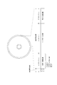
- FIG. 1 shows the layout (area configuration) of the entire disc.
- an inner zone As an area on the disk, an inner zone, a data zone, and an outer zone are arranged from the inner circumferential side.
- the recording layer is shown as a single structure (single layer), in which case the inner zone is a lead-in area and the outer zone is a lead-out area.
- the inner circumferential area of each recording layer is generically referred to as an inner zone
- the outer circumferential area of each recording layer is generically referred to as an outer zone.
- the area on the innermost circumferential side of the inner zone is taken as a read only area, and the middle of the inner zone to the outer zone is taken as a recordable area.
- a BCA Breast Cutting Area
- PIC Pre-Recorded Information Area
- the inner zone structure of the multi-layer disc of two or more layers will be described later, but the PIC is only the first layer (layer L0), and the recording layer of the second layer (layer L1) and later has the same radius as PIC It becomes possible area.
- the recordable area is used to record various management / control information.
- recording tracks are formed in a spiral shape by wobbling grooves (serpent grooves).
- the groove is used as a guide for tracking when tracing by a laser spot, and this groove is made a recording track to perform data recording and reproduction.
- an optical disk in which data recording is performed on a groove is assumed, but the present invention is not limited to such an optical disk for groove recording, but a land recording method for recording data on a land between grooves
- the present invention may be applied to an optical disc, or may be applied to an optical disc of a land / groove recording system in which data is recorded in grooves and lands.
- the groove as the recording track has a meandering shape corresponding to the wobble signal. Therefore, in the disk drive for the optical disk, both edge positions of the groove are detected from the reflected light of the laser spot irradiated to the groove, and the disk at both edge positions when moving the laser spot along the recording track The wobble signal can be reproduced by extracting the fluctuation component in the radial direction.
- address information (physical address, other additional information, etc.) of the recording track at the recording position is modulated. Therefore, in the disk drive apparatus, address control and the like can be performed at the time of recording and reproduction of data by demodulating address information and the like from the wobble signal.
- a data unit of 2048 bytes is called a sector, and 32 sectors (65536 bytes) are continuously configured to form a data unit called a cluster.
- One cluster is the minimum unit of data writing.
- the sector corresponds to the first data unit in the claims, and the cluster corresponds to the second data unit.
- writing is performed on recording tracks in cluster units. Reading of data is possible in units of sectors.
- the inner zone shown in FIG. 1 is, for example, an area inside a radius of 24 mm. Then, in PIC (pre-recorded information area) in the inner zone, disc information such as recording / reproducing power conditions, area information on the disc, information used for copy protection, etc. are pre-reproduced as information dedicated to reproduction by wobbling of grooves. It has been recorded. These pieces of information may be recorded by emboss pits or the like.
- BCA is provided on the inner circumferential side further than PIC.
- the BCA records a unique ID unique to the disc recording medium, for example, by a recording method for burning out the recording layer. That is, the recording marks are formed concentrically to form barcode-shaped recording data.
- a predetermined area format including a temporary defect management area (TDMA), an optimum power control area (OPC), an information area (INFO), a reserve area RSV, a buffer area BUF, and the like is set.
- TDMA temporary defect management area
- OPC optimum power control area
- INFO information area
- RSV reserve area
- BUF buffer area
- the OPC is used for trial writing when setting data recording and reproducing conditions such as laser power at the time of recording and reproduction. That is, it is an area for adjusting the recording and reproducing conditions.
- INFO includes DMA (Defect Management Area) and control data area.
- DMA Defect Management Area
- control data area for example, disc type, disc size, disc version, layer structure, channel bit length, BCA information, transfer rate, data zone position information, recording linear velocity, recording / reproducing laser power information etc. are recorded. Ru.
- DMA is provided in INFO
- replacement information DFL described later
- DMA replacement information for defect management
- the disk of this example not only replacement management of defective portions but also management / control information for realizing data rewrite in this write-once type disk is recorded in the DMA.
- the contents of DMA must also be updated according to the data rewrite.
- TDMA is provided.
- the replacement information is additionally recorded in the TDMA and updated.
- the last (latest) replacement information finally recorded in the TDMA is recorded. The DMA and the TDMA will be described later.
- a radius of 24.0 to 58.0 mm on the outer peripheral side than the inner zone is used as a data zone.
- the data zone is an area where user data is actually recorded and reproduced.
- the start address and the end address of the data zone are indicated in the data zone position information of the control data area described above.
- the data zone is a user data area, and is used for recording and reproducing user data.
- An outer peripheral side of the data zone for example, a radius of 58.0 to 58.5 mm is an outer zone (for example, a lead-out zone).
- Management / control information is also recorded in the outer zone. That is, INFO (control data area, DMA, buffer area) is formed in a predetermined format.
- Various control / control information is also recorded in the control data area of the outer zone, as in the control data area in the inner zone, for example.
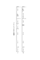
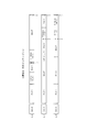
- FIG. 2 shows an example of the inner zone layout of a two-layer disc and FIG. 3 shows a three-layer disc.
- a protection zone PZ1 is provided in each of the layers L0 and L1 for the purpose of separating the BCA from the area for recording and reproducing management information.
- the PIC in which the management information only for reproduction is recorded in the wobbling groove is formed.
- a protection zone PZ2 a buffer area BUF, an INFO # 2, an OPC (L0), a TDMA # 1, and an INFO # 1 are sequentially arranged toward the outer peripheral side of the PIC.
- a buffer area BUF, OPC (L1), reserve area RSV, INFO # 4, TDMA # 2, reserve area RSV, INFO # 3 are sequentially arranged.
- the buffer area BUF is an area not used for recording and reproduction of management information.
- the reserve area RSV is an area which is not used at present but may be used for recording and reproduction of management information in the future.
- TDMA and INFO are shown with # 1 to #n, they are used as one TDMA and one INFO area as a whole, regardless of the layer to be arranged.
- PIC is arranged on the outer peripheral side following the BCA and the protection zone PZ1.
- the BCA, the protection zone PZ, and the PIC become the reproduction only area.
- the protection zone PZ2 the buffer area BUF, the INFO # 2, the OPC (L0), the TDMA # 1, and the INFO # 1 are arranged toward the outer peripheral side.
- FIG. 2 and FIG. 3 above are an example.
- an area capable of storing a DFL entry described later may be prepared.
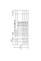
- FIG. 4 shows the structure of DMA.
- the size of DMA is 32 clusters (32 ⁇ 65536 bytes) is shown.
- a cluster is the minimum unit of data recording.
- the DMA size is not limited to 32 clusters.
- each cluster of 32 clusters is shown as cluster numbers 1 to 32 and the data position of each content in DMA is shown. Also, the size of each content is shown as the number of clusters.
- DMA disc definition structure
- Area management information of the user data area is recorded in the DDS.
- the DDS has a size of one cluster, and is repeatedly recorded four times in the section of the four clusters.
- the section of four clusters of cluster numbers 5 to 8 is the first recording area (DFL # 1) of the defect list DFL.
- the defect list DFL is data of 4 cluster sizes, in which information indicating each replacement status (DFL entry described later) is listed up.
- the section of four clusters of cluster numbers 9 to 12 is the second recording area (DFL # 2) of the defect list DFL.
- recording areas for the third and subsequent defect lists DFL # 3 to DFL # 6 of four clusters are prepared, and the section of four clusters of cluster numbers 29 to 32 is the seventh recording area of the defect list DFL (DFL # 7 ). That is, seven recording areas of the defect lists DFL # 1 to DFL # 7 are prepared for the DMA of 32 clusters.
- the seven defect lists DFL # 1 to DFL # 7 written to the DMA all have the same contents.
- the written content is the latest TDMA content.
- the contents of the DDS and the defect list DFL need to be updated sequentially according to data rewriting etc. In that case, information substantially similar to the contents of the DMA will be recorded in the TDMA. Then, the latest contents of the TDMA become the DMA contents at the current time (or at the closing time).
- FIG. 5 shows the structure of the defect list DFL.
- the defect list DFL is recorded in the recording area of four clusters.
- the first 64 bytes of the defect list DFL is used as defect list management information.
- the defect list management information information such as information identifying that the defect list is a cluster, a version, the number of times of updating the defect list, and the number of entries in the defect list are recorded. Further, after the byte position 64, 8-byte DFL entries are recorded as the entry contents of the defect list, that is, to indicate specific replacement address information. Then, immediately after the last valid DFL entry #N, eight bytes of terminator information as the end of the DFL entry are recorded. In this DFL, the end of the cluster is filled with 00h after the end of the DFL entry.
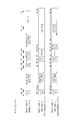
- FIG. 6 shows the structure of the DFL entry.
- the BD-R is a write-once disc and it is not possible to rewrite data at the recorded position on the disc
- the data rewrite is performed by a method called LOW. That is, to rewrite the already recorded data, the update data is recorded at another position on the disc, and the original address is associated with the new address by replacement information.
- this replacement information is a DFL entry.
- the DFL entry two types of entry types "0" and “1” are defined as the DFL entry. Further, for the entry type "1", the subtype "0""1" is further defined. Thereby, three types of DFL entries shown in FIG. 6 are defined.
- the DFL entry of entry type “0” is an entry as normal replacement information.
- a DFL entry of subtype “0""1" as entry type "0” is an entry as extended sparing information.
- the DFL entry of entry type “0” is also referred to as “alternate entry”
- the DFL entry of subtype “0” or “1” as entry type “0” is also referred to as “extension entry”. I assume.
- extension entry of subtype "0” is referred to as a "first extension entry”
- extension entry of subtype "1” is referred to as a "second extension entry”.
- One DFL entry is composed of 8 bytes (64 bits). Each bit is shown as bits b63 to b0.
- the DFL entry (replacement entry) of entry type "0" as normal replacement information will be described.
- An entry type “0” is recorded in bit b63 of the replacement entry.
- the bits b62 to b39 indicate the physical address (PCN: Pysical Cluster Number) of the replacement source cluster (replacement source PCN). That is, they indicate clusters replaced by defects or rewriting.
- a valid data flag (Valid Data Flag) is recorded in bit b38. This is information indicating whether or not the dummy write is registered.
- An unrecorded flag is recorded in a bit b37. This is information indicating whether or not an unrecorded defect is registered.
- the extend flag is recorded in bit b36. This is information indicating whether there is an extended entry (DFL entry of entry type “1”) associated with this entry. Normally, although the extend flag is set to 0, as described later, an extended entry may be generated in a state of being linked to the alternate entry according to the status of the rewrite operation. In that case, the extend flag of the alternate entry is set to 1.
- the bits b35 to b12 indicate the physical address (PCN) of the replacement destination cluster (replacement destination PCN). That is, when a cluster is replaced due to a defect or a rewrite, the cluster to be replaced is indicated. That is, in one replacement entry, replacement address information is formed in a format in which the relationship between the replacement source PCN and the replacement destination PCN is indicated.
- PCN physical address
- An entry type "1” is recorded in bit b63 of the first extended entry.
- Information (bit map PCN) of an address (PCN) of a cluster indicating a sector bit map in the first extended entry is indicated by bits b62 to b39.
- bitmap PCN As this bitmap PCN, a replacement destination PCN in the linked replacement entry is assigned.
- Subtype "0" is recorded in bit b38. Bits b37 to b32 are reserved.
- 32 bits of bits 31 to b0 are taken as a sector bit map. For each of the 32 sectors constituting the cluster indicated by the bit map PCN, this is information indicating whether the sector is an effective sector or an invalid sector by one bit. For example, "0" is an effective sector, and "1" is an invalid sector. By referring to this sector bit map, it is possible to confirm whether each of the 32 sectors is valid or invalid in the cluster indicated by the bit map PCN.
- An entry type "1” is recorded in bit b63 of the second extended entry.
- Bits b62 to b39 indicate a bit map PCN indicating a replacement destination PCN in the linked replacement entry, as in the first extended entry.
- Subtype "1" is recorded in bit b38.
- Bits b37 to b32 are reserved.
- the previous LOW Cluster Number is recorded. This indicates the replacement PCN at the time of LOW where RMW succeeded before the previous time in view of the current LOW at which this second extended entry is to be registered. This is information indicating a cluster that goes back during RMW.
- RMW is performed when performing data rewriting in units of sectors at LOW.
- RMW reads the data of the cluster including that sector, merges the data of the sector to be updated (update data) and the data of the read sector (recorded data). This is a series of operations for creating new cluster unit data and recording at the alternate address.
- the first extension entry is registered together with the replacement entry at or after the RMW failure.
- the sector bit map is optimized (merged) and registered.
- the second extended entry is registered as an entry including the previous replacement PCN together with the replacement entry upon RMW failure or later.
- Addition of the extension entry is performed according to the following rules (a), (b) and (c).
- (B) When RMW succeeds when there is an extended entry: Register a first extended entry having a sector bit map obtained by merging the sector write information at that time and the previous sector bit map. Also, a second extension entry is added with the previous previous LOW cluster number and bitmap start flag 1, and the previous extension entry is deleted.
- C When the RMW fails when there is an extension entry Only the sector write information at that time is made valid, and the first and second extension entries are added, and the previous extension entry is stored as it is.
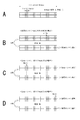
- FIG. 7A shows 32 bits as a sector bit map. If all the sectors of the target cluster are valid sectors, all 32 bits will be "0". However, such a situation is a state at the time of reading success of RMW without the extended entry, and does not correspond to the above rule, and the extended entry is not formed, so the extended entry having such sector bit map actually exists do not do.
- FIG. 7B shows a sector bit map of the extended entry formed in the case corresponding to the above (a).
- the sector indicated by the arrow Write in the upper part of FIG. 7B is the target of rewriting (sector writing). It is assumed that reading of RMW failed at this time.
- the data of the sector to be rewritten that is, the update data supplied from the host is recorded in the replacement destination cluster indicated in the replacement entry updated according to the LOW, but due to the read failure of the RMW, the update Sectors other than data sectors become invalid data. Therefore, as shown in the lower part of the figure, the sector bit map is information indicating that only the sector in which the update data is recorded is valid and the other sectors are invalid sectors.
- FIG. 7C shows a sector bit map of the extended entry formed in the case corresponding to the above (b).
- the upper part of FIG. 7C shows the state of the lower part of FIG. 7B.
- the sector indicated by the arrow Write is a target of sector write.
- RMW has succeeded in reading.
- FIG. 7D shows a sector bit map of the extended entry formed in the case corresponding to the above (c).
- the upper part of FIG. 7D shows the state of the lower part of FIG. 7C.
- the sector indicated by the arrow Write is a target of sector write. It is assumed that reading of RMW failed at this time.
- the update data of the rewrite target sector is recorded in the replacement destination cluster indicated in the replacement entry updated according to the current LOW, but due to a read failure, sectors other than the sector in which the update data is recorded are invalid. It becomes data. Therefore, as shown in the lower part of the figure, the sector bit map is information in which only the sector in which the update data is recorded is valid and the other sectors are invalid sectors.
- the sector bit map of the previous extension entry since the sector bit map of the previous extension entry has information of other valid sectors, it can be stored and referred to.
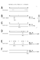
- FIG. 8 shows the alternation of clusters and the transition of sector bit map
- FIG. 9 shows the state of DFL entry at each time point.
- the data rewrite is repeated several times for the original cluster CL-A, and the address (PCN) of the replacement destination is cluster CL-A.fwdarw.CL-A'.fwdarw.CL-B.fwdarw.CL-C.fwdarw.
- CL-D ⁇ CL-E ⁇ CL-F changes is taken as an example.
- FIG. 8A and FIG. 9A show the state after LOW accompanied by replacement from cluster CL-A to CL-A ′.
- RMW in LOW is normally performed. Therefore, all sectors in cluster CL-A 'are valid, so all sector bitmaps in FIG. 8A are "0" (although no extended entry is registered at this point, so this sector bitmap does not exist).
- FIG. 8B and FIG. 9B show the state after LOW accompanied by replacement from cluster CL-A ′ to CL-B. It is assumed that the sector SC-x shown in FIG. 8B is to be rewritten. It is assumed that the RMW in this case is performed normally. Therefore, since all the sectors of the cluster CL-B are valid, the sector bit map of FIG. 8B is all "0" (although no sector bit map exists at this point either).
- FIG. 8C and FIG. 9C show the state after LOW accompanied by replacement of cluster CL-B to CL-C.
- Sector SC-y is to be updated. It is assumed that the RMW in this case is performed normally. Therefore, since all sectors of cluster CL-C are valid, the sector bit map of FIG. 8C is all "0" (although no sector bit map exists at this point either).
- the replacement entry E2 is deleted.
- the 1st extended entry E5 and the 2nd extended entry E6 are registered in the state where it is stringed by replacement entry E4.
- the extend flag is set to 1 in the alternate entry E4.
- the effective sector in the cluster CL-D With reference to the first expansion entry E5.
- FIGS. 8E and 9E show the state after LOW accompanied by replacement of cluster CL-D to CL-E. It is assumed that the sector SC-w is to be updated. In this case, it is assumed that RMW read succeeded. For example, it is assumed that necessary sector data, that is, sector data other than the sector SC-w can be read out from the cluster CL-D or cluster CL-C, and they can be merged to rewrite data.
- the replacement entry E4 is deleted.
- the first extended entry E8 and the second extended entry E9 are registered in a state of being linked to the replacement entry E7.
- the extend flag in the alternate entry E7 is set to 1.
- FIGS. 8F and 9F show the state after LOW accompanied by replacement from cluster CL-E to CL-F. It is assumed that the sector SC-v is to be updated. In this case, it is assumed that RMW read failed.
- the replacement entry E7 is deleted.
- the 1st extended entry E11 and the 2nd extended entry E12 are registered in the state where it is stringed by replacement entry E10.
- the extend flag in the alternate entry E10 is set to 1.
- the existing extended entries E8 and E9 are maintained as they are without being deleted.
- the effective sector in the cluster CL-F can be determined.
- the second expansion entry E9 it can be determined that data of effective sectors can be collected retroactively to the cluster CL-C.
- the extended entry is registered under the predetermined conditions of rules (a), (b) and (c) in the DFL entry, so that the presence and location of valid sector data can be confirmed with reference to the DFL entry. It will be in the state.
- the above-mentioned replacement entry, the first extended entry, and the second extended entry have their bit assignments devised so that the sorting order is suitable for processing when they are sorted.
- the above alternate entry, the first extended entry, and the second extended entry are registered as the 8-bit DFL entries in FIG. 5, but the disk drive side of the DFL entries is listed in ascending or descending order. Sort and process. For example, when sorting in ascending order, normal replacement entries are arranged, and then first and second extended entries are arranged in PCN order. This is because 8-bit DFL entries are assigned in the order of entry type, PCN, and subtype from the MSB side as shown in FIG. By doing this, even if the expansion entry is added, processing on the disk drive side is not complicated.
- Disk drive device configuration As an example of the recording apparatus of the present disclosure, a disk drive apparatus that performs recording and reproduction on the above-described optical disk will be described.
- FIG. 10 shows the configuration of the disk drive device.
- the disk 1 is the disk of the embodiment described above.
- the disk 1 is loaded on a turntable (not shown), and is rotationally driven by a spindle motor 52 at constant linear velocity (CLV: Constant Linear Velocity) or constant angular velocity (CAV: Constant Angular Velocity) at the time of recording / reproducing operation.
- the optical pickup (optical head) 51 reads the ADIP address embedded as wobbling of the groove track on the disk 1 and management / control information as pre-recorded information.
- management / control information and user data are recorded on the track in the recordable area by the optical pickup 51, and the data recorded by the optical pickup 51 is read at the time of reproduction.
- a laser diode serving as a laser light source, a photodetector for detecting reflected light, an objective lens serving as an output end of the laser beam, and a laser beam are irradiated onto the disc recording surface through the objective lens
- An optical system (not shown) for guiding the reflected light to the photodetector is formed.
- the objective lens is held movably in the tracking direction and the focusing direction by a biaxial mechanism.
- the entire optical pickup 51 is movable in the radial direction of the disc by a sled mechanism 53.
- the laser diode in the optical pickup 51 is driven to emit a laser beam by a drive signal (drive current) from the laser driver 63.
- Reflected light information from the disk 1 is detected by a photodetector in the optical pickup 51, converted into an electrical signal according to the amount of light received, and supplied to the matrix circuit 54.
- the matrix circuit 54 is provided with a current-voltage conversion circuit, a matrix operation / amplification circuit and the like corresponding to output currents from a plurality of light receiving elements as photodetectors, and generates necessary signals by matrix operation processing. For example, a high frequency signal (reproduction data signal) corresponding to reproduction data, a focus error signal for servo control, a tracking error signal and the like are generated. Furthermore, a push-pull signal is generated as a signal related to groove wobbling, that is, a signal for detecting wobbling.
- the matrix circuit 54 may be integrally formed in the optical pickup 51.
- the reproduction data signal output from the matrix circuit 54 is supplied to the reader / writer circuit 55, the focus error signal and the tracking error signal are supplied to the servo circuit 61, and the push-pull signal is supplied to the wobble circuit 58.
- the reader / writer circuit 55 performs binarization processing, reproduction clock generation processing by PLL, etc. on the reproduction data signal, reproduces the data read by the optical pickup 51, and supplies it to the modulation / demodulation circuit 56.
- the modulation / demodulation circuit 56 has a functional part as a decoder at the time of reproduction and a functional part as an encoder at the time of recording. At the time of reproduction, demodulation processing of a run-length limited code is performed based on the reproduction clock as decoding processing.
- the ECC encoder / decoder 57 performs an ECC encoding process that adds an error correction code at the time of recording, and an ECC decoding process that performs an error correction at the time of reproduction.
- the data demodulated by the modulation / demodulation circuit 56 is taken into an internal memory, and processing such as error detection / correction processing and deinterleaving is performed to obtain reproduction data.
- the data decoded to reproduction data by the ECC encoder / decoder 57 is read based on the instruction of the system controller 60 and transferred to the connected host device 120.
- the host device 120 is, for example, a computer device or an AV (Audio-Visual) system device.
- the push-pull signal output from the matrix circuit 54 as a signal related to groove wobbling is processed by the wobble circuit 58.
- the push-pull signal as ADIP information is demodulated into a data stream constituting an ADIP address in the wobble circuit 58 and supplied to the address decoder 59.
- the address decoder 59 decodes the supplied data, obtains the address value, and supplies it to the system controller 60.
- the address decoder 59 generates a clock by PLL processing using the wobble signal supplied from the wobble circuit 58, and supplies the clock to each unit as an encode clock at the time of recording, for example.
- the push-pull signal as pre-recorded information is subjected to band pass filter processing in the wobble circuit 58 to be a reader / writer. It is supplied to the circuit 55. Then, the data is binarized into a data bit stream, and the data is decoded and deinterleaved by the ECC encoder / decoder 57 to extract data as prerecorded information. The extracted prerecorded information is supplied to the system controller 60.
- the system controller 60 can perform various operation setting processing, copy protection processing, and the like based on the read prerecorded information.
- recording data (new recording data or data for updating recording data) is transferred from the host device 120, but the recording data is sent to the memory in the ECC encoder / decoder 57 and buffered. .
- the ECC encoder / decoder 57 adds an error correction code, interleaves, adds a subcode, etc. as an encoding process of buffered recording data.
- the ECC encoded data is subjected to modulation of RLL (1-7) PP method (RLL; Run Length Limited, PP: Parity preserve / Prohibit rmtr (repeated minimum transition run length)) in the modulation / demodulation circuit 56, and the reader / It is supplied to the writer circuit 55.
- RLL 1--7
- PP method RLL; Run Length Limited
- PP Parity preserve / Prohibit rmtr (repeated minimum transition run length)
- the recording data generated by the encoding process is subjected to recording compensation processing by the reader / writer circuit 55.
- the recording layer characteristics, the spot shape of the laser beam, the fine adjustment of the optimum recording power with respect to the recording linear velocity, etc. And the like are sent to the laser driver 63 as a laser drive pulse.
- the laser driver 63 applies the supplied laser drive pulse to the laser diode in the optical pickup 51 to drive laser light emission. As a result, pits corresponding to the recording data are formed on the disc 1.
- the laser driver 63 has a so-called APC circuit (Auto Power Control), and the output of the laser depends on the temperature while monitoring the laser output power by the output of the detector for monitoring the laser power provided in the optical pickup 51. Control to be constant.
- the target values of the laser output at the time of recording and reproduction are given from the system controller 60, and control is performed so that the laser output level becomes the target value at the time of recording and reproduction, respectively.
- the servo circuit 61 generates various servo drive signals of focus, tracking, and sled from the focus error signal and the tracking error signal from the matrix circuit 54 to execute the servo operation. That is, the focus drive signal and the tracking drive signal are generated according to the focus error signal and the tracking error signal, and the focus coil and the tracking coil of the biaxial mechanism in the optical pickup 51 are driven. Thus, a tracking servo loop and a focus servo loop are formed by the optical pickup 51, the matrix circuit 54, the servo circuit 61, and the biaxial mechanism.
- the servo circuit 61 turns off the tracking servo loop in response to a track jump command from the system controller 60 and outputs a jump drive signal to execute a track jump operation.
- the servo circuit 61 generates a thread drive signal based on a thread error signal obtained as a low frequency component of the tracking error signal, access execution control from the system controller 60 and the like, and drives the thread mechanism 53.
- the sled mechanism 53 has a mechanism including a main shaft for holding the optical pickup 51, a sled motor, a transmission gear, etc., and drives the sled motor according to a sled drive signal, thereby requiring the optical pickup 51. Slide movement is performed.
- the spindle servo circuit 62 controls the spindle motor 52 to rotate at CLV or CAV.
- the spindle servo circuit 62 obtains a clock generated by PLL processing on the wobble signal as the current rotational speed information of the spindle motor 52, and compares this with the predetermined reference speed information of CLV or CAV to obtain a spindle error signal.
- a reproduction clock (a clock serving as a reference of decoding processing) generated by the PLL in the reader / writer circuit 55 serves as the current rotational speed information of the spindle motor 52.
- a spindle error signal can also be generated by comparison with reference speed information.
- the spindle servo circuit 62 outputs a spindle drive signal generated according to the spindle error signal, and causes the spindle motor 52 to rotate.
- the spindle servo circuit 62 also generates a spindle drive signal in response to a spindle kick / brake control signal from the system controller 60, and executes operations such as start, stop, acceleration, and deceleration of the spindle motor 52.
- the various operations of the servo system and the recording and reproducing system as described above are controlled by a system controller 60 formed by a microcomputer.
- the system controller 60 executes various processes in accordance with a command from the host device 120.
- the system controller 60 when a write command (write command) is issued from the host device 120, the system controller 60 first moves the optical pickup 51 to an address to be written. Then, the ECC encoder / decoder 57 and the modulation / demodulation circuit 56 execute the encoding process on the data transferred from the host device 120 as described above. Then, recording is performed by supplying the laser drive pulse from the reader / writer circuit 55 to the laser driver 63 as described above.
- a read command for transferring certain data recorded on the disk 1 is supplied from the host device 120
- access operation control is performed for the designated address. That is, a command is issued to the servo circuit 61, and the access operation of the optical pickup 51 targeting the address designated by the read command is executed. Thereafter, operation control necessary to transfer data of the instructed data section to the host device 120 is performed. That is, data is read from the disk 1, and the reader / writer circuit 55, the modulation / demodulation circuit 56, the ECC encoder / decoder 57 execute decoding / buffering and the like, and the requested data is transferred.
- data reading is performed as the above-mentioned RMW, but also in this case, the system controller 60 performs the same reading control for a cluster including a sector to be rewritten.
- the system controller 60 can control access and recording and reproducing operations using the ADIP address detected by the wobble circuit 58 and the address decoder 59.
- the system controller 60 records a unique ID recorded in the BCA of the disc 1 and pre-recorded information (PIC) recorded as a wobbling groove in the reproduction only area. Execute the reading of In that case, first, seek operation control is performed for the purpose of BCA and PIC. That is, a command is issued to the servo circuit 61 to execute the access operation of the optical pickup 51 to the innermost circumference side of the disc. Thereafter, the reproduction trace by the optical pickup 51 is executed, the push-pull signal as the reflected light information is obtained, and the decoding process by the wobble circuit 58, the reader / writer circuit 55, and the ECC encoder / decoder 57 is executed. As a result, reproduction data as BCA information and prerecorded information is obtained. The system controller 60 performs laser power setting, copy protection processing, and the like based on the BCA information and pre-recording information thus read out.
- PIC pre-recorded information
- a cache memory 60 a is shown in the system controller 60.
- the cache memory 60a is used, for example, for information read from the TDMA of the disk 1 and for updating thereof.
- the system controller 60 controls each unit to read out various management information recorded in the TDMA, and holds the read management information in the cache memory 60a.
- Information on the above-mentioned DFL entry is also included.
- the management information in the cache memory 60a is updated. For example, when the management information including the DFL entry is updated in which the replacement process is performed by LOW, the management information may be additionally recorded in the TDMA of the disk 1 each time.
- the management information is updated in the cache memory 60a until the disk 1 is ejected from the disk drive device. Then, at the time of ejection or the like, the final (latest) management information in the cache memory 60a is written to the TDMA of the disk 1. Then, a large number of updates of the management information are collected and updated on the disk 1, and the TDMA consumption of the disk 1 can be reduced.
- the configuration example of the disk drive device of FIG. 10 is an example of the disk drive device connected to the host device 120, there may be a form not connected to other devices.
- an operation unit and a display unit are provided, and the configuration of an interface portion for data input and output is different from that shown in FIG. That is, recording and reproduction may be performed according to the user's operation, and a terminal portion for input and output of various data may be formed.
- various other configuration examples can be considered, for example, a recording only apparatus and a reproduction only apparatus can also be considered.
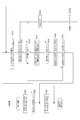
- FIG. 11 shows the processing of the system controller 60 at the time of data rewriting as LOW.
- step S10 When the system controller 60 receives a write command for a certain sector from the host device 120 and sector data as update data, the system controller 60 advances the process of FIG. 11 from step S10 to step S11 to perform read control. This is control of data reading as RMW. Specifically, the system controller 60 controls each unit to read data of a cluster including a sector to be rewritten. Then, the update data of the sector to be rewritten and the recorded data of another sector are merged to generate write data in cluster units. Then, in step S12, the system controller 60 performs write control on the disk 1 of the write data in units of clusters generated in step S11. The system controller 60 controls each unit to execute data writing as described above. In this case, the designated write position is the unrecorded PCN on the disc 1.
- This PCN is the replacement destination PCN.
- the system controller 60 updates management information in accordance with the current data rewrite. Specifically, update of information on the next writable position, update of the above-mentioned DFL entry, and the like are performed.
- the management information may be updated on the TDMA information read in the cache memory 60a, but may be written on the disk 1. Alternatively, the period in which the disk 1 is loaded may be updated in the cache memory 60a, and the disk 1 may be written at a predetermined timing such as disk ejection or power off.
- FIG. 12 shows an example of processing when the extended entry is not used in the read control of step S11 of FIG.
- the system controller 60 first performs read control of data of a cluster including a rewrite target sector in step S101. That is, it is a cluster including a sector instructed to be rewritten by the host device 120. If the data of the cluster can be read properly by the read operation according to the read control, the system controller 60 proceeds from step S102 to S103, and the update data for the sector to be rewritten and the sector data of the read cluster Are merged to generate write data in cluster units, and the process proceeds to data write control (step S12 in FIG. 11). The above is the case where the reading can be completed normally.
- step S150 sector information included in the cluster in which the read error has occurred is read.
- sector status and PLA Previous Location Address
- the sector status is information indicating validity / invalidity etc. for each sector in the cluster.
- PLA is the address of the cluster that was replaced in the previous rewrite.
- sector information may or may not be read. If the sector information can not be read out, the system controller 60 proceeds from step S151 to step S158 and determines that a read error has occurred. Then, since valid sector data other than the sector to be rewritten at this time can not be collected, merge is performed using invalid data at step S159 to generate write data in cluster units. That is, each sector other than the sector to which the update data of this time is placed generates write data in cluster units as invalid data (for example, "0" data), and proceeds to data write control (step S12 in FIG. 11). .
- step S151 determines whether or not it is possible to go back to another cluster. That is, whether or not another cluster is shown as PLA. If the data can not be traced back, a read error is determined in step S158, and merging using dummy data is performed in step S159.
- step S153 When going back to another cluster, the system controller 60 proceeds to step S153 and performs readout control of data of the cluster shown in the PLA, ie, the place where the data was previously recorded. If the other clusters are successfully read, the system controller 60 proceeds from step S154 to step S156 to merge the data of valid sectors of the read clusters. However, reading of a cluster which has been traced back once does not necessarily result in the data of all necessary effective sectors being aligned.
- the required effective sector here means, for example, all sectors other than the sector to be updated this time. Therefore, in step S157, it is determined whether the necessary sector data is complete. That is, it is determined whether data of all sectors other than the sector data to be updated this time can be read and merged.
- step S157 If valid sector data is prepared as all the sectors other than the sector to be updated this time, the system controller 60 proceeds from step S157 to S103, and merges the read valid sector data and the update data. Since this makes it possible to form cluster unit write data not including dummy data, the process proceeds to data write control (step S12 in FIG. 11). That is, even when reading of a cluster having a sector to be recorded fails, sector data can be collected retroactively to clusters recorded in the past, so that a read error does not occur.
- step S157 if it is determined in step S157 that the necessary sector data is not complete, the system controller 60 returns to step S152, refers to the sector information of the cluster read back, and can go back further (PLA is shown) Check). If it can go back, steps S153 to S156 are performed, or if it can not go back, a read error is made in step S158.
- step S150 the system controller 60 returns from step S154 to step S150 to read out the sector information of the cluster for which the reading has failed. Then, the above processing is performed depending on whether the sector information can be read out.
- step S11 of FIG. 11 takes a long time, and the response to the write command to the host device 120 eventually decreases.
- the above-mentioned extended entry is recorded on the disk 1 and the disk drive device does not go out even if the reading at the time of LOW fails. Is used to perform efficient sector data recovery or read error determination.
- FIG. 13 shows read control (process example I) of step S11 of FIG. 11 by the disk drive device of the embodiment.
- the system controller 60 first performs read control of the data of the cluster to be recorded in step S101. That is, it is a cluster including a sector instructed to be rewritten by the host device 120.
- the replacement destination cluster of the replacement entry is to be read.
- step S102 the system controller 60 proceeds from step S102 to step S103, and the update data for the sector to be rewritten and the sector data of the read cluster Are merged to generate write data in cluster units, and the process proceeds to data write control (step S12 in FIG. 11).
- step S12 the process up to this point is the same as the comparative example of FIG.
- step S110 the system controller 60 acquires sector information of the cluster in which the read error has occurred from the DFL entry. That is, among the DFL entries, a replacement entry in which a cluster for which data reading has failed this time is registered as a replacement destination cluster is searched. Then, in step S111, the system controller 60 confirms whether or not the extended entry associated with the replacement entry in which the cluster is the replacement destination cluster has been registered.
- step S111 the system controller 60 proceeds from step S111 to step S117 and determines that a read error has occurred. Then, since valid sector data other than the sector to be rewritten at this time can not be collected, merge is performed using invalid data in step S118 to generate write data in cluster units. That is, each sector other than the sector to which the update data of this time is placed generates write data in cluster units as invalid data (for example, "0" data), and proceeds to data write control (step S12 in FIG. 11). .
- step S111 the system controller 60 proceeds from step S111 to step S112 to check whether still valid sector data can be read. That is, the sector bit map of the first expansion entry, the previous LOW cluster number of the second expansion entry, and the bit map start flag are checked, and it is checked whether retroactive reading is possible for sector data recovery. . If there is a possibility that valid sector data can be read, that is, if it is not retroactive, the process proceeds to step S113, where sector data requiring complementation are recorded based on the information of the extended entry (address: The PCN and the sector number are specified, and data read control for the address is performed.
- step S114 If necessary sector data can be read, the system controller 60 proceeds from step S114 to step S115 to merge data of valid sectors of the read cluster. Also in this case, data of all necessary effective sectors may not necessarily be prepared by reading out the complementary data once. Also in this case, the necessary sectors mean, for example, all sectors other than the sectors to be updated by the current write command. Therefore, in step S116, it is determined whether the necessary sector data is complete. That is, it is whether or not the data of each sector other than the sector to be updated this time can be read and merged.
- step S116 If valid sector data are prepared as all sectors other than the sector to be updated this time, the system controller 60 proceeds from step S116 to step S103, and merges the read valid sector data and the update data. Since this makes it possible to form cluster unit write data of sector data not including dummy data, the process proceeds to data write control (step S12 in FIG. 11). That is, even when reading of a cluster having a recording target sector fails, sector data can be collected retroactively to clusters recorded in the past with reference to the DFL entry, so that a read error does not occur.
- step S114 If the system controller 60 determines in step S114 that reading has failed, the process returns to step S112. If it is determined in step S116 that the data of the necessary sector is not complete yet, the process returns to step S112. In these cases, if retroactive is still possible, data read control is performed at a place where data that needs complementation is recorded in step S113 based on the information of the DFL entry. On the other hand, when the necessary sector data is not available, the state in which the data can not be traced back in step S112, that is, when there is no information for further tracing back in the DFL entry, is determined as a read error in step S117 and step S118. Merge is performed using invalid data, and the process proceeds to data write control (step S12 in FIG. 11).
- step S113 A specific example of the above process, in particular the process of step S113 will be described with reference to FIG.
- the DFL entry is currently in the state of FIG. 9D.
- the host device 120 supplies a write command and update data instructing rewriting of a certain sector in the cluster CL-A.
- the cluster CL-D indicated by the replacement destination PCN of the replacement entry E4 at the current time is to be read, but if reading fails and processing proceeds to step S112,
- alternate entry E4 and extended entries E5 and E6 are retrieved.
- the reading of the valid sector can be tried in step S113.
- the cluster CL-C is confirmed from the previous LOW cluster number of the second extended entry E6, the cluster CL-C is accessed, and the necessary sector data is It can be collected. In some cases, this process can collect necessary sector data for merging.
- the DFL entry is in the state of FIG. 9F.
- the host device 120 supplies a write command and update data for instructing a certain sector in the cluster CL-A to be rewritten.
- the cluster CL-F indicated by the replacement destination PCN of the replacement entry E10 at the current time is to be read.
- a replacement entry E10 and extended entries E8, E9, E11 and E12 are searched for this cluster CL-F. Since the valid sector of the cluster CL-F can be confirmed from the sector bit map of the first expansion entry E11, the reading of the valid sector can be tried in step S113.
- the recording position (address) of sector data that needs to be complemented for merge processing for generating write data in cluster units can be determined directly from the DFL entry. This significantly improves the access efficiency as compared with the comparative example in which clusters are read one by one to check whether a valid sector exists. Therefore, the time required for sector data recovery can be considerably shortened.
- the DFL entry can be confirmed in the cache memory 60a, and disk access is not necessary for confirmation of the sector bit map and the previous LOW cluster number, which leads to improvement in processing efficiency and access efficiency.
- it is possible to determine a read error when it is determined that the DFL entry can not make a turn it is possible to shorten the time when a read error occurs. From these things, the processing time of step S11 of FIG. 11 is shortened, and the response to the host device 120 is also improved.
- FIG. 14 shows read control (processing example II) of step S11 of FIG.
- the same processing as that of FIG. 13 is assigned the same step number and the detailed description is omitted.
- the process example II of FIG. 14 when the system controller 60 fails to read a cluster including a sector instructed to be rewritten from the host device 120 in step S102, the process proceeds to steps S110 and S111 as in FIG. If there is an entry, it is determined from the information of the DFL entry whether or not the alternate cluster can be read continuously in step S121.
- replacement clusters can be read continuously because the clusters to which data has been written at a plurality of LOW times in the past, that is, all clusters to be traced back to collect sector data, are on disk 1 It refers to the case of physical continuity. For example, in the case of FIG. 9F, it is determined by the PCN whether or not the clusters CL-F, CL-E, and CL-C are physically continuous clusters.
- a replacement cluster which writes data when LOW is designated by NWA (Next Writable Address) recorded as management information, for example, in TDMA.
- NWA Next Writable Address
- This NWA is information indicating a PCN to which writing can be performed next. Then, every time the data rewrite operation is performed, the NWA is updated so that the next PCN to which the writing has been performed is designated. Therefore, if sector data of a cluster is updated repeatedly, replacement clusters are likely to be physically continuous. When there is such a situation, it is efficient to read a plurality of clusters in the past by continuously reading the plurality of clusters. Therefore, when the replacement cluster can be read out continuously, the system controller 60 proceeds from step S121 to step S122, and controls to read out the plurality of clusters continuously.
- step S123 it is determined whether data of necessary sectors other than the sector data to be updated this time is complete, and if it is complete, the process proceeds to step S103.
- step S123 if it is determined in step S123 that the reading has failed or if it is determined in step S125 that the necessary sectors are not aligned, a read error is determined in step S117, and merging using invalid data is performed in step S118. The process proceeds to light control (step S12 in FIG. 11).
- step S121 If it is determined in step S121 that the alternate cluster can not be read out continuously, the system controller 60 performs the processing of steps S112, S113, S114, S115, and S116. This is similar to the process of FIG.
- step S122 is performed when all of the plurality of clusters that can be traced are physically continuous, but may be applied to some continuous clusters. That is, if some of the plurality of clusters that can be recognized to be traceable by the DFL entry are physically continuous, it is also natural to read the continuous clusters once in succession. It is possible. This can also improve the lead efficiency.
- the DFL entry update process will be described with reference to FIG.
- the system controller 60 needs updating of the DFL entry. That is, as described with reference to FIGS. 8 and 9, processing of generating / updating a replacement entry or generating an extension entry according to the write status is performed.
- the system controller 60 updates the replacement entry (DFL entry of entry type "0") in step S30. That is, as described in FIG. 9, a replacement entry is generated in which a replacement destination PCN indicating a new replacement destination cluster corresponds to a replacement source cluster (replacement source PCN).
- the extend flag if the existing replacement entry (hereinafter referred to as “old replacement entry”) is “1” at this time, the replacement entry to be generated for updating is also “1”. Even if the old replacement entry is "0”, a read error has occurred this time, and if it corresponds to the above-described extension entry addition rule (a), the extension entry is generated, so The extend flag is set to 1. If the extension flag of the old replacement entry is 0 and no read error occurs this time, the extension flag is set to 0 also for the replacement entry generated for updating.
- step S31 the process branches depending on whether a read error has occurred in the current RMW. If a read error has not occurred, the process branches depending on whether or not there is a corresponding extended entry in step S32. It should be noted that the presence or absence of the extended entry in this case refers not to the replacement entry generated in step S30, but to the extend flag of the old replacement entry. If a read error does not occur and no extension entry exists, no extension entry is generated because none of the above-mentioned rules (a), (b) and (c) of the extension entry applies. Then, the system controller 60 deletes the old replacement entry in step S40 and ends the DFL update process. This is the DFL updating process in the case described with reference to FIGS. 9A, 9B, and 9C.
- rule (b) applies. Therefore, the system controller 60 searches for the corresponding extended entry in step S33, merges the sector bit map in step S34, and adds the first and second extended entries. In step S35, the existing extension entry is deleted. Then, the system controller 60 deletes the old replacement entry in step S40 and ends the DFL update process. This is the DFL update process in the case described in FIG. 9E.
- the system controller 60 branches the processing in step S36 depending on whether or not there is a corresponding extended entry. If the extension entry does not exist, the rule (a) is met. Therefore, the system controller 60 generates and registers the extension entry in step S39. Specifically, the system controller 60 sets the entry type “1”, the subtype “0”, and the replacement destination PCN as a bitmap PCN, and generates a first extended entry having a sector bitmap corresponding to the bitmap PCN. .
- the disk drive device writes data in a cluster (second data unit) in which a plurality of sectors (first data unit of a predetermined data amount) are continuous to the disk 1 (recording medium) and in sector units And a write / read unit capable of reading out data.
- the write / read unit includes the optical pickup 51, spindle motor 52, sled mechanism 53, matrix circuit 54, reader / writer circuit 55, modulation / demodulation circuit 56, ECC encoder / decoder 57, wobble circuit 58, servo circuit 61, spindle servo circuit 62 is a component by the laser driver 63.
- the disk drive apparatus further includes a system controller 60 as a control unit.
- the system controller 60 In response to a sector data rewrite instruction from the host device 120, the system controller 60 generates write data in units of clusters using update data relating to the rewrite instruction and the recorded data read from the disk 1, The write / read unit is instructed to write the embedded data to the unrecorded address on the disk 1 (LOW to execute RMW). Further, the system controller 60 generates or updates replacement information (replacement entry) that associates the address to which the write data is written with the address of the replacement source as the replacement destination, and further indicates the predetermined rules (a), (b) and (c).
- extended replacement information including valid / invalid information (sector bit map) for each sector in the write data is generated as information linked to the replacement entry.
- Write data including update data is recorded at a different position on the disk 1 from the recorded data, and data replacement on the write-once disk becomes possible by managing the replacement information.
- the data write by the write / read unit is in cluster units, but when the host device 120 gives an instruction for data rewrite in sector units, the sector for reading the recorded clusters and updating with the valid sector data Merge data to generate cluster unit data, and write to disk 1. It is a so-called RMW. At this time, even if reading of a cluster fails once, valid sector data may be able to be read by accessing a past replacement cluster.
- the DFL entry is referred to in the present embodiment. This is because the valid sector can be determined by the DFL entry. As a result, it is not necessary to read past clusters to determine valid sectors, and the access efficiency for sector data recovery is significantly improved. Therefore, the read processing time in the RMW can be shortened, and the response to the host device 120 can be improved.
- the system controller 60 refers to the extension entry when reading of the necessary recorded data for data generation in cluster units can not be performed as reading of the recorded data according to the rewrite instruction (read at the time of RMW). Then, another address at which the necessary already recorded data is recorded is confirmed, and control is made to cause the write / read unit to execute reading of data from the other address (S110 to S113). Since it is possible to confirm the address where valid data as necessary recorded data is recorded by referring to the extended sparing information, even if necessary recorded data can not be read from the target address of the rewrite instruction, It is possible to efficiently grasp the other addresses and try to read the recorded data.
- the system controller 60 determines that there is a read error when the recorded data required to generate the write data in the cluster unit can not be read even if the read from all other addresses that can be confirmed by the extended sparing information is performed. (S117). That is, if the read from the address targeted for the rewrite instruction is unsuccessful, it does not constitute a read error by itself, but it tries to read from the address confirmed by the extended entry, which is also necessary. It is assumed that a read error occurs when already recorded data can not be obtained. As a result, read errors can be avoided as much as possible, and the possibility of data rewrite by the original RMW operation can be enhanced.
- the system controller 60 when reading of necessary already recorded data from the disk 1 is successful, the system controller 60 combines the update data relating to the rewrite instruction and the read previously recorded data to generate write data (S103). On the other hand, when it is determined that the read error has occurred, the update data relating to the rewrite instruction and the invalid data are combined to generate write data in cluster units (S118). As a result, even if the necessary already recorded data can not be read out, at least the update data relating to the rewrite instruction is written to the disc 1. That is, even if reading of the RMW fails, writing of update data instructed from the host is executed, so that the recording reliability can be improved.
- the system controller 60 generates an extended entry under the condition that the read error is determined (S38, S39). This is the case of the above-described rules (a) and (c). Even if a read error occurs, if rewriting data is written, an address for which a read error occurs in RMW can be traced to the past recorded data by creating and registering an extended entry. become. That is, an extension entry is created when it is most needed.
- the system controller 60 maintains both the existing extended sparing information and the generated extended sparing information (S38). By coexistence of the new extended replacement information and the existing extended replacement information, it is possible to read out the recorded data including the part of the reading error in the past.
- the system controller 60 writes the write data generated by combining the update data relating to the rewrite instruction and the recorded data to the disc 1, an extended entry for the recorded data exists.
- the extension entry including valid / invalid information (sector bit map) of the existing extension entry is generated, and the existing extension entry is deleted (S34, S35).
- the existing extension entry is deleted (S34, S35). It is a process in the case of the above-mentioned rule (b). This is because the recorded data including the read error in the past, if the extended replacement information has been generated according to the read error in the past, even if the read of the recorded data succeeded and the rewriting can be appropriately performed To generate extended replacement information by merging existing extended replacement information. In this case, since the existing extended sparing information becomes unnecessary, the DFL entry can be made more efficient and the capacity can be reduced by deleting it.
- system controller 60 writes and reads continuously read data from the plurality of continuous clusters.
- the control to be executed is performed (S121, S122). If there are physically continuous clusters that can be read out of the recorded data, access can be made efficient by accessing and reading out the plurality of clusters at one time.
- the system controller 60 also instructs the write / read unit to write management data including the alternate entry and the extended entry to the disk 1.
- the management information including the DFL entry may be updated on the cache memory 60a, but is written to the disk 1 at a predetermined timing such as disk ejection or power off. As shown in FIGS. 13 and 14, even when the disc 1 is ejected and reloaded or is loaded into another disc drive by writing management data including the alternate entry and the extended entry to the disc 1. It is possible to recover sector data referring to the DFL entry.
- the system controller 60 also generates or updates a replacement entry such that the latest replacement address corresponds to the replacement source address in the first rewriting operation. Further, as the expansion entry, the PCN of the cluster that became the replacement destination in the rewrite operation, the first expansion entry including the sector bit map in that PCN, the PCN of the cluster that became the replacement destination in the rewrite operation, and the current LOW. In view of the above, the second expansion entry including the replacement PCN at the time of LOW where RMW has succeeded before the previous time is generated. With this structure, the function as an alternate entry and an extended entry, in particular, a minimum information storage function as information to be referred to for recovery of sector data is realized.
- the disk 1 as the recording medium of the present embodiment is linked to a sparing entry that associates the address at which the write data including the update data is written by the data rewriting operation as the sparing destination with the sparing source address, and the sparing entry.
- a management information area (for example, an inner zone including TDMA) is provided which records management data including information and extended entries including valid / invalid information of sectors in a cluster as write data.
- the recording apparatus refers to the management data to the presence of the valid recorded data for configuring the update data and its address at the time of data rewriting. Can be confirmed.
- the management information structure in the disk 1 for example, the format of the DFL entry, and the type as the replacement entry and the extension entry are merely an example.
- RMW it is sufficient if it is an information format in which identification of sector data effective as management information and its address can be confirmed at least.
- each processing described with reference to FIGS. 11, 13, 14 and 15 is also an example, and various modifications are naturally assumed.
- the recording medium of the present invention is a recording medium of various recording methods and shapes such as next-generation optical disks other than BD, card media, hologram media, volume recording media, etc., and can be applied as a write-once recording medium.
- the recording apparatus and the recording method of the present invention can be applied as a recording apparatus and its recording method corresponding to these various recording media.
- the effect described in this specification is an illustration to the last, is not limited, and may have other effects.
- a write / read unit capable of performing data writing in a second data unit in which a plurality of first data units of a predetermined data amount are continuous and data reading in the first data unit on a recording medium ,
- write data of the second data unit is generated using update data according to the rewrite instruction and recorded data read from the recording medium, and writing Instructs the write / read unit to write the embedded data to the unrecorded address on the recording medium, and generates or updates replacement information that associates the address at which the write data is written with the address of the replacement source as the replacement destination.
- a control unit that generates extended replacement information including valid / invalid information about each data of the first data unit in the write data according to a predetermined condition as information linked to the replacement information.
- the control unit In the case where the necessary recorded data can not be read out when the recorded data is read out from the recording medium according to the rewriting instruction, another recorded data is recorded with reference to the extended sparing information.
- the recording apparatus according to (1) wherein an address is confirmed, and control is performed to cause the write / read unit to execute reading of data from the other address.
- the control unit can not read out the recorded data necessary for generating the write data of the second data unit even when reading from all other addresses that can be confirmed by the extended sparing information In the case, it is determined that a read error occurs.
- the control unit When reading of the necessary already recorded data from the recording medium is successful, the update data relating to the rewrite instruction and the already recorded data read out are combined to generate write data of the second data unit, The recording apparatus according to (3), wherein when the read error is determined, the update data relating to the rewrite instruction and the invalid data are combined to generate write data of the second data unit. (5) The control unit The recording apparatus according to (4), wherein the extended sparing information is generated on condition that the read error is determined. (6) The control unit The recording apparatus according to (5), wherein when the extended replacement information for the recorded data for which the reading has been unsuccessful exists, both the existing extended replacement information and the generated extended replacement information are maintained.
- the control unit When writing on a recording medium of write data generated by combining update data relating to the rewrite instruction and the recorded data is performed, the extended sparing information on the recorded data exists And generating the extended replacement information including the valid / invalid information of the existing extended replacement information and deleting the existing extended replacement information, the record according to any one of (4) to (6) above. apparatus.
- the control unit When the plurality of second data units whose addresses can be confirmed with reference to the extended replacement information are physically continuous on the recording medium, the continuous reading of data from the plurality of continuous second data units is performed.
- the recording apparatus according to any one of (2) to (7), which performs control to be executed by the write and read unit.
- the control unit instructs the write / read unit to write management data including the replacement management information and the extended replacement management information to the recording medium. Recording device as described.
- the control unit The replacement information is generated or updated such that the address of the latest replacement destination corresponds to the address of the replacement source in the first rewriting operation, As the extended replacement information, An address of a second data unit which has become a replacement destination in the rewriting operation, and first extended replacement information including valid / invalid information of each data of the first data unit in the second data unit; The address of the second data unit which has become the replacement destination in the rewrite operation, and the second extended replacement information including the address of the replacement destination in the previous rewrite operation is generated according to any one of the above (1) to (9).
- a write / read unit capable of performing data writing in a second data unit in which a plurality of first data units of a predetermined data amount are continuous and data reading in the first data unit on a recording medium
- write data of the second data unit is generated using update data according to the rewrite instruction and recorded data read from the recording medium, and writing A procedure for instructing the write and read unit to write embedded data to an unrecorded address on a recording medium;
- a procedure for generating or updating replacement information that associates the address at which the write data is written with the address of the replacement source as the replacement destination; Generating, according to a predetermined condition, extended replacement information including valid / invalid information about each data of the first data unit in the write data as information linked to the replacement information.
Abstract
データ書換の際のRMWで読出失敗データの回復を行う場合に効率的なアクセスを実現するため、記録装置は、記録媒体に対して所定データ量の第1データ単位が複数連続する第2データ単位でのデータ書込及び第1データ単位でのデータ読出を行うことができる書込読出部と制御部を備える。制御部は、データの書換指示に応じて、該書換指示に係る更新用データと記録媒体から読み出した既記録データを用いて、第2データ単位の書込データを生成し、書込データを記録媒体上の未記録アドレスに書き込むように書込読出部に指示するとともに、書込データを書き込んだアドレスを交替先として交替元のアドレスに対応づける交替情報を生成又は更新し、さらに所定条件に応じて、書込データにおける第1データ単位の各データについての有効/無効情報を含む拡張交替情報を、交替情報に紐づけた情報として生成する。
Description
本技術は記録装置、記録方法、記録媒体に関し、特にライトワンス型の記録媒体に係るデータ書換についての技術分野に関する。
BD(ブルーレイディスク:Blu-ray Disc(登録商標))やDVD(Digital Versatile Disc)等の光記録媒体が知られており、例えばそれらの種別においてBD-R(Blu-ray Disc Recordable)、DVD-R(Digital Versatile Disc Recordable)といったライトワンス型の光ディスクも広く利用されている。
上記特許文献1にはライトワンス型の記録媒体に対するデータの書換(更新)を行う手法が開示されている。
上記特許文献1にはライトワンス型の記録媒体に対するデータの書換(更新)を行う手法が開示されている。
例えばBDの場合、2048バイトのデータ単位がセクタと呼ばれ、32セクタ(65536バイト)でクラスタと呼ばれるデータ単位が構成される。そして1クラスタがデータ書き込みの最小単位となる。
BD-Rのようなライトワンスディスクの場合、ディスク上の既記録位置においてデータ書換を行うことはできない。そこで既に記録されたデータの書換は、更新するデータをディスク上の他の位置に記録し、交替情報で元のアドレスと新たなアドレスを対応づけることにより実現する。この手法をLOW(Logical Over Write)と呼ぶ。
アドレスの対応は、欠陥交替技術を利用しており、つまり元のクラスタを欠陥と同じように扱って、交替元と交替先を紐付けて管理している。
BD-Rのようなライトワンスディスクの場合、ディスク上の既記録位置においてデータ書換を行うことはできない。そこで既に記録されたデータの書換は、更新するデータをディスク上の他の位置に記録し、交替情報で元のアドレスと新たなアドレスを対応づけることにより実現する。この手法をLOW(Logical Over Write)と呼ぶ。
アドレスの対応は、欠陥交替技術を利用しており、つまり元のクラスタを欠陥と同じように扱って、交替元と交替先を紐付けて管理している。
このLOWでセクタ単位のデータ書換を実行する際には、RMW(Read Modify Write)が必要である。
これはセクタライトを実行する前に、そのセクタを含む既記録のクラスタのデータを読み込み、更新したいセクタと読み込んだセクタのデータをマージして新しいクラスタ単位のデータを作り、交替先のアドレスに記録を行う一連の動作である。上述のようにクラスタがデータ書込単位であるため、このようにRMWを行うことで、既記録の有効なセクタデータに更新用のセクタデータを合成した新たなクラスタデータを記録できる。つまりセクタ単位の書換が可能となる。
これはセクタライトを実行する前に、そのセクタを含む既記録のクラスタのデータを読み込み、更新したいセクタと読み込んだセクタのデータをマージして新しいクラスタ単位のデータを作り、交替先のアドレスに記録を行う一連の動作である。上述のようにクラスタがデータ書込単位であるため、このようにRMWを行うことで、既記録の有効なセクタデータに更新用のセクタデータを合成した新たなクラスタデータを記録できる。つまりセクタ単位の書換が可能となる。
ところがこの場合に、読出の失敗により既記録データが取得できないと、最適状態で書換ができない。ところが、単に交替元のクラスタから読出が失敗しても、さらに以前に書換が行われていた場合、他のアドレスから有効なセクタデータが取得できる可能性もある。そこで、読出失敗時には、過去にさかのぼって有効なデータを探索することを行う。
しかしながら、過去の有効なデータの探索のために一つずつさかのぼったアドレスでデータ読出を行って、有効なセクタを判定していくということが必要で、アクセス時間を要する。そして最後まで読み出せなかった場合には読出エラーとなる。結局これが記録装置のレスポンス低下につながり、システムによっては書換動作にとって非常に不都合なケースを生じさせるおそれがある。
そこで本技術はライトワンス型の記録媒体の書換動作の効率化を図ることを目的とする。
しかしながら、過去の有効なデータの探索のために一つずつさかのぼったアドレスでデータ読出を行って、有効なセクタを判定していくということが必要で、アクセス時間を要する。そして最後まで読み出せなかった場合には読出エラーとなる。結局これが記録装置のレスポンス低下につながり、システムによっては書換動作にとって非常に不都合なケースを生じさせるおそれがある。
そこで本技術はライトワンス型の記録媒体の書換動作の効率化を図ることを目的とする。
本技術に係る記録装置は、記録媒体に対して、所定データ量の第1データ単位が複数連続する第2データ単位でのデータ書込及び前記第1データ単位でのデータ読出を行うことができる書込読出部と、前記第1データ単位のデータの書換指示に応じて、該書換指示に係る更新用データと前記記録媒体から読み出した既記録データを用いて、前記第2データ単位の書込データを生成し、書込データを記録媒体上の未記録アドレスに書き込むように前記書込読出部に指示するとともに、前記書込データを書き込んだアドレスを交替先として交替元のアドレスに対応づける交替情報を生成又は更新し、さらに所定条件に応じて、前記書込データにおける前記第1データ単位の各データについての有効/無効情報を含む拡張交替情報を、前記交替情報に紐づけた情報として生成する制御部とを備える。
更新用データを既記録データとは記録媒体上の異なる位置に記録することでデータ書換を行う方式により、いわゆるライトワンス型の記録媒体でのデータ書換が可能となる。
ここで書込読出部によるデータ書込単位が第2データ単位(クラスタ)とされる場合に、当該記録装置のホスト機器からは、第1データ単位(セクタ)のデータ書換の指示があるとする。記録装置は、第2データ単位の書込データを生成するために、書換の対象となる第1データ単位のデータを含む第2データ単位のデータを記録媒体から読み出す。そして読み出した第2データ単位における書換対象とはなっていない第1データ単位のデータと更新用データをマージして第2データ単位のデータ長の書込データを生成し、該書込データを、交替先のアドレスに書き込むという動作を行う。このような書換動作においては、常に既記録データが、対象のアドレスから読み出せるとは限らないが、書換動作が複数回行われている場合、有効な既記録データが他のアドレスに存在している場合がある。
拡張交替情報を設定しておくことにより、更新データを構成するための有効な既記録データの存在やそのアドレスが、管理情報参照して確認できる。
上記した記録装置においては、前記制御部は、前記書換指示に応じた記録媒体からの既記録データの読出において、必要な既記録データの読出ができなかった場合、前記拡張交替情報を参照して必要な既記録データが記録されている他のアドレスを確認し、当該他のアドレスからのデータの読出を前記書込読出部に実行させる制御を行う。
拡張交替情報を参照して、必要な既記録データとしての有効データが記録されているアドレスが確認できるため、例えば書換指示の対象となっているアドレスからは必要な既記録データが読み出せない場合が生じても、効率よく、他のアドレスを把握して、既記録データの読出を試みることができる。
拡張交替情報を参照して、必要な既記録データとしての有効データが記録されているアドレスが確認できるため、例えば書換指示の対象となっているアドレスからは必要な既記録データが読み出せない場合が生じても、効率よく、他のアドレスを把握して、既記録データの読出を試みることができる。
上記した記録装置においては、前記制御部は、前記拡張交替情報で確認できる全ての他のアドレスからの読出を行っても前記第2データ単位の書込データの生成に必要な既記録データの読出ができなかった場合に、読出エラーと判定する。
例えば書換指示の対象となっているアドレスからの読出が不成功であった場合、それだけでは読出エラーとはせず、さらに拡張交替情報で確認したアドレスからの読出を試行し、確認できる全てのアドレスからの読出を行っても必要な既記録データが揃わなかった場合に読出エラーとする。
例えば書換指示の対象となっているアドレスからの読出が不成功であった場合、それだけでは読出エラーとはせず、さらに拡張交替情報で確認したアドレスからの読出を試行し、確認できる全てのアドレスからの読出を行っても必要な既記録データが揃わなかった場合に読出エラーとする。
上記した記録装置においては、前記制御部は、前記記録媒体から必要な既記録データの読み出しが成功した場合は、前記書換指示に係る更新用データと読み出した既記録データを合成して、前記第2データ単位の書込データを生成し、前記読出エラーと判定した場合は、前記書換指示に係る更新用データと無効データを合成して、前記第2データ単位の書込データを生成する。
必要な既記録データが読み出せなかった場合は、少なくとも書換指示に係る書換データが書き込まれるようにする。
必要な既記録データが読み出せなかった場合は、少なくとも書換指示に係る書換データが書き込まれるようにする。
上記した記録装置においては、前記制御部は、前記読出エラーと判定したことを条件として、前記拡張交替情報を生成する。
読出エラーとなった場合でも、書換データの書き込みは行われる。そこで、読出エラーとなったアドレスについては、拡張交替情報を生成して登録することで、その後、過去の既記録データが辿れるようにする。
読出エラーとなった場合でも、書換データの書き込みは行われる。そこで、読出エラーとなったアドレスについては、拡張交替情報を生成して登録することで、その後、過去の既記録データが辿れるようにする。
上記した記録装置においては、前記制御部は、読み出しが不成功となった既記録データについての拡張交替情報が存在している場合は、既存の拡張交替情報と、生成した拡張交替情報の両方を維持する。
新規の拡張交替情報と既存の拡張交替情報を併存させることで、過去の読出エラーの分も含めて、拡張交替情報を用いて既記録データを辿ることができる。
新規の拡張交替情報と既存の拡張交替情報を併存させることで、過去の読出エラーの分も含めて、拡張交替情報を用いて既記録データを辿ることができる。
上記した記録装置においては、前記制御部は、前記書換指示に係る更新用データと前記既記録データを合成して生成した書込データの記録媒体への書込が行われた場合、前記既記録データについての前記拡張交替情報が存在していることを条件として、既存の拡張交替情報の前記有効/無効情報を含む拡張交替情報を生成するとともに、当該既存の拡張交替情報を削除する。
既記録データの読出が成功して適切に書換が実行できても、過去に読出エラーに応じて拡張交替情報が生成されていた場合、過去の読出エラーの分も含めて既記録データが辿れるように、既存の拡張交替情報をマージした拡張交替情報を生成する。この場合、既存の拡張交替情報は不要になるため削除する。
既記録データの読出が成功して適切に書換が実行できても、過去に読出エラーに応じて拡張交替情報が生成されていた場合、過去の読出エラーの分も含めて既記録データが辿れるように、既存の拡張交替情報をマージした拡張交替情報を生成する。この場合、既存の拡張交替情報は不要になるため削除する。
上記した記録装置においては、前記制御部は、前記拡張交替情報を参照してアドレスを確認できる複数の前記第2データ単位が記録媒体上で物理的に連続している場合、当該連続した複数の第2データ単位からのデータの連続読出を前記書込読出部に実行させる制御を行う。
既記録データの読出に溯ることができる第2データ単位が物理的に連続していれば、それらの複数の第2データ単位に対して一度にアクセスして読み出すようにする。
既記録データの読出に溯ることができる第2データ単位が物理的に連続していれば、それらの複数の第2データ単位に対して一度にアクセスして読み出すようにする。
上記した記録装置においては、前記制御部は、前記交替管理情報及び前記拡張交替管理情報を含む管理データを前記記録媒体に書き込むように前記書込読出部に指示する。
交替管理情報及び拡張交替管理情報を含む管理データを記録媒体に書き込むことで、記録媒体のイジェクトや他の記録装置でも対応できるようにする。
交替管理情報及び拡張交替管理情報を含む管理データを記録媒体に書き込むことで、記録媒体のイジェクトや他の記録装置でも対応できるようにする。
上記した記録装置においては、前記制御部は、前記交替情報を、最初の書換動作における交替元のアドレスに対して最新の交替先のアドレスが対応されるように生成又は更新するとともに、前記拡張交替情報として、書換動作において交替先となった第2データ単位のアドレスとその第2データ単位における前記第1データ単位の各データの有効/無効情報を含む第1の拡張交替情報と、書換動作において交替先となった第2データ単位のアドレスと前回以前の書換動作における交替先のアドレスを含む第2の拡張交替情報と、を生成する。
この構造により、交替情報、拡張交替情報としての機能を実現する。
この構造により、交替情報、拡張交替情報としての機能を実現する。
本技術に係る記録方法は、記録媒体に対して、所定データ量の第1データ単位が複数連続する第2データ単位でのデータ書込及び前記第1データ単位でのデータ読出を行うことができる書込読出部を備えた記録装置の記録方法として、前記第1データ単位のデータの書換指示に応じて、該書換指示に係る更新用データと前記記録媒体から読み出した既記録データを用いて、前記第2データ単位の書込データを生成し、書込データを記録媒体上の未記録アドレスに書き込むように前記書込読出部に指示する手順と、前記書込データを書き込んだアドレスを交替先として交替元のアドレスに対応づける交替情報を生成又は更新する手順と、所定条件に応じて、前記書込データにおける前記第1データ単位の各データについての有効/無効情報を含む拡張交替情報を、前記交替情報に紐づけた情報として生成する手順とを備える。
つまり必要に応じて拡張交替情報を設定しておくことにより、更新データを構成するための有効な既記録データの存在やそのアドレスが、管理情報を参照して確認できるようにする。
つまり必要に応じて拡張交替情報を設定しておくことにより、更新データを構成するための有効な既記録データの存在やそのアドレスが、管理情報を参照して確認できるようにする。
本技術に係る記録媒体は、ユーザーデータと管理データが記録されるとともに、所定データ量の第1データ単位が複数連続する第2データ単位でのデータ書込が行われ、前記第1データ単位のデータの書換の際には、更新用データと既記録データにより前記第2データ単位の書込データが、未記録アドレスに書き込まれる記録媒体であって、データ書換動作により書込データを書き込んだアドレスを交替先として交替元のアドレスに対応づける交替情報と、前記交替情報に紐づいた情報であって、前記書込データにおける前記第1データ単位の各データについての有効/無効情報を含む拡張交替情報と、を含む管理データを記録する管理情報領域が設けられている。
管理情報領域に拡張交替情報を記録可能な記録媒体とすることで、データ書換の際に記録装置が、更新データを構成するための有効な既記録データの存在やそのアドレスを管理データを参照して確認できるものとなる。
管理情報領域に拡張交替情報を記録可能な記録媒体とすることで、データ書換の際に記録装置が、更新データを構成するための有効な既記録データの存在やそのアドレスを管理データを参照して確認できるものとなる。
本技術によれば、ライトワンス型の記録媒体の書換動作を効率化でき、レスポンスのよい記録装置を実現できる。
なお、ここに記載された効果は必ずしも限定されるものではなく、本開示中に記載されたいずれかの効果であってもよい。
なお、ここに記載された効果は必ずしも限定されるものではなく、本開示中に記載されたいずれかの効果であってもよい。
以下、実施の形態を次の順序で説明する。
<1.ディスク構造>
<2.DMA及びDFLエントリ>
<3.ディスクドライブ装置の構成>
<4.データ書換処理>
<5.まとめ及び変形例>
<1.ディスク構造>
<2.DMA及びDFLエントリ>
<3.ディスクドライブ装置の構成>
<4.データ書換処理>
<5.まとめ及び変形例>
<1.ディスク構造>
実施の形態では、請求項にいう記録媒体の例として、いわゆるブルーレイディスクと呼ばれる高密度光ディスク方式の範疇におけるライトワンス型ディスク(BD-R)を挙げる。
実施の形態では、請求項にいう記録媒体の例として、いわゆるブルーレイディスクと呼ばれる高密度光ディスク方式の範疇におけるライトワンス型ディスク(BD-R)を挙げる。
本実施の形態の高密度光ディスクの物理パラメータの一例について説明する。
本例の光ディスクは、ディスクサイズとしては、直径が120mm、ディスク厚は1.2mmとなる。
そして記録/再生のためのレーザとして、いわゆる青色レーザが用いられ、また光学系が高NA(例えばNA=0.85)とされる。さらには狭トラックピッチ(例えばトラックピッチ=0.32μm)、高線密度(例えば記録線密度0.12μm)を実現する。これらにより、直径12cmのディスクにおいて、ユーザーデータ容量として23G~25GB(Giga Byte)程度を実現している。また更なる高密度記録により、30GB程度の容量も可能とされる。
また、記録層が複数層とされたいわゆるマルチレイヤーディスクも開発されており、マルチレイヤーディスクの場合、ユーザーデータ容量は、ほぼ層数倍となる。
図1にディスク全体のレイアウト(領域構成)を示す。
ディスク上の領域としては、内周側からインナーゾーン、データゾーン、アウターゾーンが配される。
なお、この図1では記録層が1つの構造(シングルレイヤ)で示しており、その場合、インナーゾーンはリードインエリア、アウターゾーンはリードアウトエリアとなる。説明の便宜上、マルチレイヤーディスクの場合も、各記録層の内周側領域をインナーゾーンと総称し、各記録層の外周側領域をアウターゾーンと総称する。
ディスク上の領域としては、内周側からインナーゾーン、データゾーン、アウターゾーンが配される。
なお、この図1では記録層が1つの構造(シングルレイヤ)で示しており、その場合、インナーゾーンはリードインエリア、アウターゾーンはリードアウトエリアとなる。説明の便宜上、マルチレイヤーディスクの場合も、各記録層の内周側領域をインナーゾーンと総称し、各記録層の外周側領域をアウターゾーンと総称する。
記録・再生に関する領域構成としてみれば、インナーゾーン(リードインエリア)のうちの最内周側の領域が再生専用領域とされ、インナーゾーンの途中からアウターゾーンまでが、記録可能領域とされる。
再生専用領域にはBCA(Burst Cutting Area)やPIC(プリレコーデッド情報領域)が設けられる。但し2層以上のマルチレイヤディスクのインナーゾーン構造については後述するが、PICは第1層(レイヤL0)のみとなり、第2層(レイヤL1)以降の記録層では、PICと同一半径部分は記録可能領域となる。
またインナーゾーンにおいて、記録可能領域は、各種の管理/制御情報の記録に用いられる。
再生専用領域にはBCA(Burst Cutting Area)やPIC(プリレコーデッド情報領域)が設けられる。但し2層以上のマルチレイヤディスクのインナーゾーン構造については後述するが、PICは第1層(レイヤL0)のみとなり、第2層(レイヤL1)以降の記録層では、PICと同一半径部分は記録可能領域となる。
またインナーゾーンにおいて、記録可能領域は、各種の管理/制御情報の記録に用いられる。
再生専用領域及び記録可能領域には、ウォブリンググルーブ(蛇行された溝)による記録トラックがスパイラル状に形成されている。グルーブはレーザスポットによるトレースの際のトラッキングのガイドとされ、かつこのグルーブが記録トラックとされてデータの記録再生が行われる。
なお本例では、グルーブにデータ記録が行われる光ディスクを想定しているが、本発明はこのようなグルーブ記録の光ディスクに限らず、グルーブとグルーブの間のランドにデータを記録するランド記録方式の光ディスクに適用してもよいし、また、グルーブ及びランドにデータを記録するランドグルーブ記録方式の光ディスクにも適用することも可能である。
なお本例では、グルーブにデータ記録が行われる光ディスクを想定しているが、本発明はこのようなグルーブ記録の光ディスクに限らず、グルーブとグルーブの間のランドにデータを記録するランド記録方式の光ディスクに適用してもよいし、また、グルーブ及びランドにデータを記録するランドグルーブ記録方式の光ディスクにも適用することも可能である。
また記録トラックとされるグルーブは、ウォブル信号に応じた蛇行形状となっている。そのため、光ディスクに対するディスクドライブ装置では、グルーブに照射したレーザスポットの反射光からそのグルーブの両エッジ位置を検出し、レーザスポットを記録トラックに沿って移動させていった際におけるその両エッジ位置のディスク半径方向に対する変動成分を抽出することにより、ウォブル信号を再生することができる。
このウォブル信号には、その記録位置における記録トラックのアドレス情報(物理アドレスやその他の付加情報等)が変調されている。そのため、ディスクドライブ装置では、このウォブル信号からアドレス情報等を復調することによって、データの記録や再生の際のアドレス制御等を行うことができる。
BDの場合、2048バイトのデータ単位がセクタと呼ばれ、32セクタ(65536バイト)が連続してクラスタと呼ばれるデータ単位が構成される。そして1クラスタがデータ書き込みの最小単位となる。
この場合、セクタが請求項でいう第1データ単位に相当し、クラスタが第2データ単位に相当する。
光ディスクに対するディスクドライブ装置では、記録トラックに対してクラスタ単位で書込を行う。データの読出はセクタ単位で可能である。
この場合、セクタが請求項でいう第1データ単位に相当し、クラスタが第2データ単位に相当する。
光ディスクに対するディスクドライブ装置では、記録トラックに対してクラスタ単位で書込を行う。データの読出はセクタ単位で可能である。
図1に示すインナーゾーンは、例えば半径24mmより内側の領域となる。
そしてインナーゾーン内におけるPIC(プリレコーデッド情報領域)には、あらかじめ、記録再生パワー条件等のディスク情報や、ディスク上の領域情報、コピープロテクションにつかう情報等を、グルーブのウォブリングによって再生専用情報として記録してある。なお、エンボスピット等によりこれらの情報を記録してもよい。
そしてインナーゾーン内におけるPIC(プリレコーデッド情報領域)には、あらかじめ、記録再生パワー条件等のディスク情報や、ディスク上の領域情報、コピープロテクションにつかう情報等を、グルーブのウォブリングによって再生専用情報として記録してある。なお、エンボスピット等によりこれらの情報を記録してもよい。
また、PICよりさらに内周側にBCAが設けられる。BCAはディスク記録媒体固有のユニークIDを、例えば記録層を焼き切る記録方式で記録したものである。つまり記録マークを同心円状に並べるように形成していくことで、バーコード状の記録データを形成する。
またインナーゾーンにおいては、TDMA(Temporary Defect Management Area)、OPC(Optimum Power Control area:テストライトエリア)、INFO(Information area)、リザーブエリアRSV、バッファエリアBUFなどを有する所定の領域フォーマットが設定される。
OPCは、記録/再生時のレーザパワー等、データ記録再生条件を設定する際の試し書きなどに使われる。即ち記録再生条件調整のための領域である。
INFOには、DMA(Defect Management Area )やコントロールデータエリアが含まれる。INFOにおけるコントロールデータエリアには、例えばディスクタイプ、ディスクサイズ、ディスクバージョン、層構造、チャンネルビット長、BCA情報、転送レート、データゾーン位置情報、記録線速度、記録/再生レーザパワー情報などが記録される。
INFO内にはDMAが設けられるが、通常、光ディスクの分野ではDMAは欠陥管理のための交替情報(後述するDFL)が記録される。しかしながら本例のディスクでは、DMAは、欠陥箇所の交替管理のみではなく、このライトワンス型ディスクにおけるデータ書換を実現するための管理/制御情報が記録される。
また、交替処理を利用してデータ書換を可能にするためには、データ書換に応じてDMAの内容も更新されていかなければならない。このためTDMAが設けられる。
交替情報はTDMAに追加記録されて更新されていく。DMAには、最終的にTDMAに記録された最後(最新)の交替情報が記録される。
DMA及びTDMAについては後述する。
また、交替処理を利用してデータ書換を可能にするためには、データ書換に応じてDMAの内容も更新されていかなければならない。このためTDMAが設けられる。
交替情報はTDMAに追加記録されて更新されていく。DMAには、最終的にTDMAに記録された最後(最新)の交替情報が記録される。
DMA及びTDMAについては後述する。
インナーゾーンより外周側の例えば半径24.0~58.0mmがデータゾーンとされる。データゾーンは、実際にユーザーデータが記録再生される領域である。データゾーンの開始アドレス、終了アドレスは、上述したコントロールデータエリアのデータゾーン位置情報において示される。
データゾーンはユーザーデータ領域とされ、ユーザーデータの記録再生に用いられる。
データゾーンはユーザーデータ領域とされ、ユーザーデータの記録再生に用いられる。
データゾーンより外周側、例えば半径58.0~58.5mmはアウターゾーン(例えばリードアウトゾーン)とされる。アウターゾーンも管理/制御情報が記録される。即ちINFO(コントロールデータエリア、DMA、バッファエリア)が、所定のフォーマットで形成される。
アウターゾーンのコントロールデータエリアにも、例えばインナーゾーンにおけるコントロールデータエリアと同様に各種の管理/制御情報が記録される。
アウターゾーンのコントロールデータエリアにも、例えばインナーゾーンにおけるコントロールデータエリアと同様に各種の管理/制御情報が記録される。
マルチレイヤーディスクの例として、図2に2層ディスク、図3に3層ディスクのインナーゾーンのレイアウト例を示す。
図2の2層ディスクの場合、各レイヤL0,L1においては、BCAと、管理情報の記録再生を行う領域との間を離す目的で、プロテクションゾーンPZ1が設けられる。
図2の2層ディスクの場合、各レイヤL0,L1においては、BCAと、管理情報の記録再生を行う領域との間を離す目的で、プロテクションゾーンPZ1が設けられる。
レイヤL0においては、上述したようにウォブリンググルーブで再生専用の管理情報が記録されるPICが形成される。そしてPICより外周側に向かってプロテクションゾーンPZ2、バッファエリアBUF、INFO#2、OPC(L0)、TDMA#1、INFO#1が順次配置されている。
レイヤL1においては、バッファエリアBUF、OPC(L1)、リザーブエリアRSV、INFO#4、TDMA#2、リザーブエリアRSV、INFO#3が順次配置されている。
レイヤL1においては、バッファエリアBUF、OPC(L1)、リザーブエリアRSV、INFO#4、TDMA#2、リザーブエリアRSV、INFO#3が順次配置されている。
なおバッファエリアBUFは、管理情報の記録再生に用いないエリアである。またリザーブエリアRSVは、現状では使用されていないが、将来的に管理情報の記録再生に用いる可能性があるエリアである。
TDMA、INFOについては、#1~#nを付して示しているが、配置されるレイヤに関わらず、これらが全体として1つのTDMA、1つのINFOの領域として用いられる。
TDMA、INFOについては、#1~#nを付して示しているが、配置されるレイヤに関わらず、これらが全体として1つのTDMA、1つのINFOの領域として用いられる。
図3の3層ディスクの場合、レイヤL0において、BCA、プロテクションゾーンPZ1に続いて外周側にPICが配置される。BCA、プロテクションゾーンPZ、PICが再生専用領域となる。
そしてPICに続いて、外周側に向かってプロテクションゾーンPZ2,バッファエリアBUF、INFO#2、OPC(L0)、TDMA#1、INFO#1が配置される。
そしてPICに続いて、外周側に向かってプロテクションゾーンPZ2,バッファエリアBUF、INFO#2、OPC(L0)、TDMA#1、INFO#1が配置される。
レイヤL1では、BCA、プロテクションゾーンPZ1のみが再生専用領域となる。そしてプロテクションゾーンPZ1に続いて外周側に向かって、バッファエリアBUF、OPC(L1)、リザーブエリアRSV、INFO#4、TDMA#2、リザーブエリアRSV、INFO#3が配置される。
レイヤL2でも、BCA、プロテクションゾーンPZ1のみが再生専用領域となる。そしてプロテクションゾーンPZ1に続いて外周側に向かって、バッファエリアBUF、OPC(L2)、リザーブエリアRSV、INFO#6、TDMA#3、バッファエリアBUF、INFO#5が配置される。
レイヤL2でも、BCA、プロテクションゾーンPZ1のみが再生専用領域となる。そしてプロテクションゾーンPZ1に続いて外周側に向かって、バッファエリアBUF、OPC(L2)、リザーブエリアRSV、INFO#6、TDMA#3、バッファエリアBUF、INFO#5が配置される。
なお、以上の図2,図3のレイアウトは一例である。本実施の形態の光ディスクとしては、インナーゾーンのレイアウトが以上の図2,図3と異なったとしても、後述のDFLエントリを記憶できる領域が用意されていればよい。
<2.DMA及びDFLエントリ>
インナーゾーン、アウターゾーンに記録されるDMAの構造を説明する。図4にDMAの構造を示す。
ここではDMAのサイズは32クラスタ(32×65536バイト)とする例を示す。なお、クラスタとはデータ記録の最小単位である。
もちろんDMAサイズが32クラスタに限定されるものではない。図4では、32クラスタの各クラスタを、クラスタ番号1~32としてDMAにおける各内容のデータ位置を示している。また各内容のサイズをクラスタ数として示している。
インナーゾーン、アウターゾーンに記録されるDMAの構造を説明する。図4にDMAの構造を示す。
ここではDMAのサイズは32クラスタ(32×65536バイト)とする例を示す。なお、クラスタとはデータ記録の最小単位である。
もちろんDMAサイズが32クラスタに限定されるものではない。図4では、32クラスタの各クラスタを、クラスタ番号1~32としてDMAにおける各内容のデータ位置を示している。また各内容のサイズをクラスタ数として示している。
DMAにおいて、クラスタ番号1~4の4クラスタの区間にはDDS(disc definition structure)としてディスクの詳細情報が記録される。
DDSにはユーザーデータ領域の領域管理情報が記録される。DDSは1クラスタのサイズとされ、当該4クラスタの区間において4回繰り返し記録される。
DDSにはユーザーデータ領域の領域管理情報が記録される。DDSは1クラスタのサイズとされ、当該4クラスタの区間において4回繰り返し記録される。
クラスタナンバ5~8の4クラスタの区間は、ディフェクトリストDFLの1番目の記録領域(DFL#1)となる。ディフェクトリストDFLは4クラスタサイズのデータとなり、その中に、個々の交替状況を示す情報(後述のDFLエントリ)をリストアップした構成となる。
クラスタナンバ9~12の4クラスタの区間は、ディフェクトリストDFLの2番目の記録領域(DFL#2)となる。
さらに、4クラスタずつ3番目以降のディフェクトリストDFL#3~DFL#6の記録領域が用意され、クラスタナンバ29~32の4クラスタの区間は、ディフェクトリストDFLの7番目の記録領域(DFL#7)となる。
つまり、32クラスタのDMAには、ディフェクトリストDFL#1~DFL#7の7個の記録領域が用意される。
クラスタナンバ9~12の4クラスタの区間は、ディフェクトリストDFLの2番目の記録領域(DFL#2)となる。
さらに、4クラスタずつ3番目以降のディフェクトリストDFL#3~DFL#6の記録領域が用意され、クラスタナンバ29~32の4クラスタの区間は、ディフェクトリストDFLの7番目の記録領域(DFL#7)となる。
つまり、32クラスタのDMAには、ディフェクトリストDFL#1~DFL#7の7個の記録領域が用意される。
BD-R(ライトワンス型光ディスク)の場合、このDMAの内容を記録するためには、クロージングという処理を行う必要がある。その場合、DMAに書き込む7つのディフェクトリストDFL#1~DFL#7は全て同じ内容とされる。書込内容は最新のTDMAの内容となる。
DDSやディフェクトリストDFLの内容は、データ書換などに応じて逐次更新が必要となるが、その場合、当該DMA内容とほぼ同様の情報がTDMAに記録されていくことになる。そしてTDMAの最新の内容が現時点(或いはクロージング時点)のDMA内容となる。
DDSやディフェクトリストDFLの内容は、データ書換などに応じて逐次更新が必要となるが、その場合、当該DMA内容とほぼ同様の情報がTDMAに記録されていくことになる。そしてTDMAの最新の内容が現時点(或いはクロージング時点)のDMA内容となる。
図5にディフェクトリストDFLの構造を示す。
図4で説明したようにディフェクトリストDFLは4クラスタの記録領域に記録される。
図5においては、バイト位置として、4クラスタのディフェクトリストDFLにおける各データ内容のデータ位置を示している。なお1クラスタ=32セクタ=65536バイトであり、1セクタ=2048バイトである。
バイト数は各データ内容のサイズとしてのバイト数を示す。
図4で説明したようにディフェクトリストDFLは4クラスタの記録領域に記録される。
図5においては、バイト位置として、4クラスタのディフェクトリストDFLにおける各データ内容のデータ位置を示している。なお1クラスタ=32セクタ=65536バイトであり、1セクタ=2048バイトである。
バイト数は各データ内容のサイズとしてのバイト数を示す。
ディフェクトリストDFLの先頭の64バイトはディフェクトリスト管理情報とされる。
このディフェクトリスト管理情報には、ディフェクトリストのクラスタであることを認識する情報、バージョン、ディフェクトリスト更新回数、ディフェクトリストのエントリー数などの情報が記録される。
またバイト位置64以降は、ディフェクトリストのエントリ内容、つまり具体的な交替アドレス情報を示すものとして、各8バイトのDFLエントリが記録される。
そして有効な最後のDFLエントリ#Nの直後には、DFLエントリ終端としてのターミネータ情報が8バイト記録される。
このDFLでは、DFLエントリ終端以降、そのクラスタの最後までが00hで埋められる。
このディフェクトリスト管理情報には、ディフェクトリストのクラスタであることを認識する情報、バージョン、ディフェクトリスト更新回数、ディフェクトリストのエントリー数などの情報が記録される。
またバイト位置64以降は、ディフェクトリストのエントリ内容、つまり具体的な交替アドレス情報を示すものとして、各8バイトのDFLエントリが記録される。
そして有効な最後のDFLエントリ#Nの直後には、DFLエントリ終端としてのターミネータ情報が8バイト記録される。
このDFLでは、DFLエントリ終端以降、そのクラスタの最後までが00hで埋められる。
図6にDFLエントリの構造を示す。
本実施の形態では、BD-Rがライトワンスディスクであって、ディスク上の既記録位置においてデータ書換を行うことはできないため、データ書換はLOWと呼ばれる手法で行う。即ち既に記録されたデータの書換は、更新データをディスク上の他の位置に記録し、交替情報で元のアドレスと新たなアドレスを対応づける。
この交替情報の具体例がDFLエントリとなる。
本実施の形態では、BD-Rがライトワンスディスクであって、ディスク上の既記録位置においてデータ書換を行うことはできないため、データ書換はLOWと呼ばれる手法で行う。即ち既に記録されたデータの書換は、更新データをディスク上の他の位置に記録し、交替情報で元のアドレスと新たなアドレスを対応づける。
この交替情報の具体例がDFLエントリとなる。
本実施の形態では、このDFLエントリとして、エントリタイプ“0”“1”の2つのタイプを規定している。またエントリタイプ“1”については、さらにサブタイプ“0”“1”を規定している。これにより図6に示す3種類のDFLエントリが規定される。
エントリタイプ“0”のDFLエントリは通常の交替情報としてのエントリである。
一方、エントリタイプ“0”としてのサブタイプ“0”“1”のDFLエントリは拡張交替情報としてのエントリである。
以下、説明上の区別のために、エントリタイプ“0”のDFLエントリを「交替エントリ」、エントリタイプ“0”としてのサブタイプ“0”“1”のDFLエントリを「拡張エントリ」ともいうこととする。またサブタイプ“0”の拡張エントリを「第1の拡張エントリ」、サブタイプ“1”の拡張エントリを「第2の拡張エントリ」という。
1つのDFLエントリは、8バイト(64ビット)で構成される。各ビットをビットb63~b0として示す。
まず通常の交替情報としてのエントリタイプ“0”のDFLエントリ(交替エントリ)を説明する。
交替エントリのビットb63にはエントリタイプ“0”が記録される。
ビットb62~b39には、交替元クラスタの物理アドレス(PCN:Pysical Cluster Number)が示される(交替元PCN)。即ち欠陥又は書換により交替されるクラスタを示すものである。
ビットb38にはバリッドデータフラグ(Valid Data Flag)が記録される。これはダミーライトの登録かどうかを示す情報である。
ビットb37にはアンレコーデッドフラグ(Unrecorded Flag)が記録される。これは未記録欠陥の登録かどうかを示す情報である。
交替エントリのビットb63にはエントリタイプ“0”が記録される。
ビットb62~b39には、交替元クラスタの物理アドレス(PCN:Pysical Cluster Number)が示される(交替元PCN)。即ち欠陥又は書換により交替されるクラスタを示すものである。
ビットb38にはバリッドデータフラグ(Valid Data Flag)が記録される。これはダミーライトの登録かどうかを示す情報である。
ビットb37にはアンレコーデッドフラグ(Unrecorded Flag)が記録される。これは未記録欠陥の登録かどうかを示す情報である。
ビットb36にはエクステンドフラグ(Extend Flag)が記録される。これは、このエントリに紐付けられた拡張エントリ(エントリタイプ“1”のDFLエントリ)があるかどうかを示す情報である。
通常、エクステンドフラグ=0とされるが、後述するように書換動作の状況に応じて、その交替エントリに紐づけられた状態で拡張エントリが生成される場合がある。その場合に、その交替エントリのエクステンドフラグ=1とされる。
通常、エクステンドフラグ=0とされるが、後述するように書換動作の状況に応じて、その交替エントリに紐づけられた状態で拡張エントリが生成される場合がある。その場合に、その交替エントリのエクステンドフラグ=1とされる。
ビットb35~b12には、交替先クラスタの物理アドレス(PCN)が示される(交替先PCN)。即ち、欠陥或いは書換によりクラスタが交替される場合に、その交替先のクラスタを示すものとされる。
即ち1つの交替エントリでは、交替元PCNと交替先PCNの関係が示される形式で交替アドレス情報が形成されている。
即ち1つの交替エントリでは、交替元PCNと交替先PCNの関係が示される形式で交替アドレス情報が形成されている。
ビットb11~b0にはエントリサイズ(Entry Size)が示される。1クラスタの交替であればエントリサイズ=0とされる。もし、2クラスタ以上連続する領域で交替が行われる場合、エントリサイズによって連続されるクラスタの数が示される。
例えばエントリサイズ=1の場合、交替元クラスタを先頭とする2クラスタが、交替先クラスタを先頭とする2クラスタに交替されたことを示す。エントリサイズ=2の場合、交替元クラスタを先頭とする3クラスタが、交替先クラスタを先頭とする3クラスタに交替されたことを示す。
このようなエントリサイズが管理されることで、連続する複数クラスタを交替させたときに、1つのクラスタ毎に交替エントリを生成しなくてもよいものとなる。
例えばエントリサイズ=1の場合、交替元クラスタを先頭とする2クラスタが、交替先クラスタを先頭とする2クラスタに交替されたことを示す。エントリサイズ=2の場合、交替元クラスタを先頭とする3クラスタが、交替先クラスタを先頭とする3クラスタに交替されたことを示す。
このようなエントリサイズが管理されることで、連続する複数クラスタを交替させたときに、1つのクラスタ毎に交替エントリを生成しなくてもよいものとなる。
次に第1の拡張エントリ(エントリタイプ“1”、サブタイプ“0”)について説明する。
第1の拡張エントリのビットb63にはエントリタイプ“1”が記録される。
ビットb62~b39には、当該第1の拡張エントリにおいてセクタビットマップを示すクラスタのアドレス(PCN)の情報(ビットマップPCN)が示される。このビットマップPCNとしては、紐付けされた交替エントリにおける交替先PCNがアサインされる。
ビットb38にはサブタイプ“0”が記録される。
ビットb37~b32はリザーブとされている。
第1の拡張エントリのビットb63にはエントリタイプ“1”が記録される。
ビットb62~b39には、当該第1の拡張エントリにおいてセクタビットマップを示すクラスタのアドレス(PCN)の情報(ビットマップPCN)が示される。このビットマップPCNとしては、紐付けされた交替エントリにおける交替先PCNがアサインされる。
ビットb38にはサブタイプ“0”が記録される。
ビットb37~b32はリザーブとされている。
ビット31~b0の32ビットはセクタビットマップ(Sector Bitmap)とされる。これは、ビットマップPCNで示されるクラスタを構成する32セクタのそれぞれについて、各1ビットで、有効セクタか無効セクタかを示す情報とされる。例えば“0”は有効セクタ、“1”は無効セクタとする。
このセクタビットマップを参照することで、ビットマップPCNで示されるクラスタにおいて32個の各セクタが有効であるか無効であるかを確認できる情報となっている。
このセクタビットマップを参照することで、ビットマップPCNで示されるクラスタにおいて32個の各セクタが有効であるか無効であるかを確認できる情報となっている。
次に第2の拡張エントリ(エントリタイプ“1”、サブタイプ“1”)について説明する。
第2の拡張エントリのビットb63にはエントリタイプ“1”が記録される。
ビットb62~b39には、上記第1の拡張エントリと同様に、紐付けされた交替エントリにおける交替先PCNを示すビットマップPCNが示される。
ビットb38にはサブタイプ“1”が記録される。
ビットb37~b32はリザーブとされている。
第2の拡張エントリのビットb63にはエントリタイプ“1”が記録される。
ビットb62~b39には、上記第1の拡張エントリと同様に、紐付けされた交替エントリにおける交替先PCNを示すビットマップPCNが示される。
ビットb38にはサブタイプ“1”が記録される。
ビットb37~b32はリザーブとされている。
ビットb24にはビットマップスタートフラグ(Bitmap Start Flag)が記録される。これは或る交替エントリに紐づけられた最初の拡張エントリであるか否かの情報である。或るデータ書換動作(LOW)にともなって、交替エントリに紐づけられた拡張エントリ(第1及び第2の拡張エントリ)が登録される場合、ビットマップスタートフラグ=1とされる。これはセクタビットマップの最初の情報(それ以上は拡張エントリは遡れない)であることを示す。
その後のデータ書換動作に伴って、拡張エントリが追加される場合、その拡張エントリにおけるビットマップスタートフラグ=0となる。これは、それ以前の拡張エントリが存在すること(RMWの際に遡れること)を示すものとなる。
その後のデータ書換動作に伴って、拡張エントリが追加される場合、その拡張エントリにおけるビットマップスタートフラグ=0となる。これは、それ以前の拡張エントリが存在すること(RMWの際に遡れること)を示すものとなる。
ビットb23~b0は前LOWクラスタナンバ(Previous LOW Cluster Number)が記録される。これはこの第2の拡張エントリが登録されることになった今回のLOWからみて前回以前でRMWが成功したLOWの際における交替先PCNが示される。これはRMWの際に遡るクラスタを示す情報となる。
以上の第1,第2の拡張エントリによって、RMWの際に、今回交替元となるPCNからの読出が失敗しても、他のPCNにおける有効なセクタデータの存在を確認できるようにしている。
本実施の形態においてはLOWでセクタ単位のデータ書換を実行する際には、RMWを行う。上述のようにRMWは、セクタライトを実行する前に、そのセクタを含むクラスタのデータを読み込み、更新したいセクタのデータ(更新用データ)と読み込んだセクタのデータ(既記録データ)をマージして新しいクラスタ単位のデータを作り、交替先のアドレスに記録を行う一連の動作である。
本実施の形態においてはLOWでセクタ単位のデータ書換を実行する際には、RMWを行う。上述のようにRMWは、セクタライトを実行する前に、そのセクタを含むクラスタのデータを読み込み、更新したいセクタのデータ(更新用データ)と読み込んだセクタのデータ(既記録データ)をマージして新しいクラスタ単位のデータを作り、交替先のアドレスに記録を行う一連の動作である。
ここで、第1の拡張エントリは、RMW失敗時又はそれ以降に交替エントリと一緒に登録される。この場合、セクタビットマップは最適化(マージ)されて登録される。
第2の拡張エントリは、RMW失敗時又はそれ以降に交替エントリと一緒に以前の交替先PCNを含むエントリとして登録される。一番最初の登録の場合は上述のようにビットマップスタートフラグ=1とされる。
第2の拡張エントリは、RMW失敗時又はそれ以降に交替エントリと一緒に以前の交替先PCNを含むエントリとして登録される。一番最初の登録の場合は上述のようにビットマップスタートフラグ=1とされる。
拡張エントリの追加は次の(a)(b)(c)のルールで行われる。
(a)拡張エントリがない場合
セクタライト対象クラスタについてRMWのリード失敗時に第1,第2の拡張エントリーを登録する。
(b)拡張エントリがある場合でRMWが成功した場合
その時のセクタライト情報と以前のセクタビットマップをマージしたセクタビットマップを有する第1の拡張エントリを登録する。また、以前の前LOWクラスタナンバとビットマップスタートフラグ=1で第2の拡張エントリを追加し、以前の拡張エントリを削除する。
(c)拡張エントリがある場合でRMWが失敗した場合
その時のセクタライト情報のみ有効として第1,第2の拡張エントリーを追加し、以前の拡張エントリはそのまま保存する。
(a)拡張エントリがない場合
セクタライト対象クラスタについてRMWのリード失敗時に第1,第2の拡張エントリーを登録する。
(b)拡張エントリがある場合でRMWが成功した場合
その時のセクタライト情報と以前のセクタビットマップをマージしたセクタビットマップを有する第1の拡張エントリを登録する。また、以前の前LOWクラスタナンバとビットマップスタートフラグ=1で第2の拡張エントリを追加し、以前の拡張エントリを削除する。
(c)拡張エントリがある場合でRMWが失敗した場合
その時のセクタライト情報のみ有効として第1,第2の拡張エントリーを追加し、以前の拡張エントリはそのまま保存する。
このようなルールで追加される拡張エントリにおける第1の拡張エントリのセクタビットマップの例を図7で説明する。
図7Aはセクタビットマップとしての32ビットを示している。もし対象のクラスタの全セクタが有効セクタであれば、32ビットは全て“0”となる。但し、このような状況は、拡張エントリ無しでRMWのリード成功時の状態となり、上記ルールに該当せず、拡張エントリは形成されないので、実際にはこのようなセクタビットマップを有する拡張エントリは存在しない。
図7Aはセクタビットマップとしての32ビットを示している。もし対象のクラスタの全セクタが有効セクタであれば、32ビットは全て“0”となる。但し、このような状況は、拡張エントリ無しでRMWのリード成功時の状態となり、上記ルールに該当せず、拡張エントリは形成されないので、実際にはこのようなセクタビットマップを有する拡張エントリは存在しない。
図7Bは上記(a)に該当した場合に形成される拡張エントリのセクタビットマップを示している。
今、図7Bの上段の矢印Writeで示すセクタが書換(セクタライト)の対象となったとする。このときにRMWのリードに失敗したとする。書換対象のセクタのデータ、つまりホストから供給された更新用データは、今回のLOWに応じて更新される交替エントリに示される交替先クラスタに記録されるが、RMWのリード失敗により、当該更新用データのセクタ以外のセクタは無効なデータとなる。そのためセクタビットマップは、下段に示すように、更新用データを記録したセクタのみが有効で、他のセクタについては無効セクタであることを示す情報となる。
今、図7Bの上段の矢印Writeで示すセクタが書換(セクタライト)の対象となったとする。このときにRMWのリードに失敗したとする。書換対象のセクタのデータ、つまりホストから供給された更新用データは、今回のLOWに応じて更新される交替エントリに示される交替先クラスタに記録されるが、RMWのリード失敗により、当該更新用データのセクタ以外のセクタは無効なデータとなる。そのためセクタビットマップは、下段に示すように、更新用データを記録したセクタのみが有効で、他のセクタについては無効セクタであることを示す情報となる。
図7Cは上記(b)に該当した場合に形成される拡張エントリのセクタビットマップを示している。
図7Cの上段は、図7Bの下段の状態を示している。ここで矢印Writeで示すセクタがセクタライトの対象となったとする。
このときにRMWのリードに成功したとする。すると前回に更新用データを記録したセクタと、今回更新用データを記録したセクタは有効であるため、セクタビットマップは下段に示すようになる。つまり今回の有効セクタの情報と、前回までの有効セクタの情報をマージしたセクタビットマップとする。この場合、前回のセクタビットマップは不要となるため、以前の拡張エントリを削除するとともにビットマップスタートフラグ=1とする。
図7Cの上段は、図7Bの下段の状態を示している。ここで矢印Writeで示すセクタがセクタライトの対象となったとする。
このときにRMWのリードに成功したとする。すると前回に更新用データを記録したセクタと、今回更新用データを記録したセクタは有効であるため、セクタビットマップは下段に示すようになる。つまり今回の有効セクタの情報と、前回までの有効セクタの情報をマージしたセクタビットマップとする。この場合、前回のセクタビットマップは不要となるため、以前の拡張エントリを削除するとともにビットマップスタートフラグ=1とする。
図7Dは上記(c)に該当した場合に形成される拡張エントリのセクタビットマップを示している。
図7Dの上段は図7Cの下段の状態を示している。ここで矢印Writeで示すセクタがセクタライトの対象となったとする。
このときにRMWのリードに失敗したとする。書換対象セクタの更新用データは、今回のLOWに応じて更新される交替エントリに示される交替先クラスタに記録されるが、リード失敗により、当該更新用データを記録したセクタ以外のセクタは無効なデータとなる。そのためセクタビットマップは、下段に示すように、更新用データを記録したセクタのみが有効で、他のセクタについては無効セクタとする情報となる。一方、前回の拡張エントリのセクタビットマップは、他の有効セクタの情報を有するものとなっているため、保存して参照できるようにする。
このようなセクタビットマップの変遷を伴う、LOWに応じたDFLエントリ(交替エントリ、第1の拡張エントリ、第2の拡張エントリ)の変遷を図8,図9で説明する。
図8はクラスタの交替とセクタビットマップの変遷を示し、図9は各時点でのDFLエントリの状態を示している。
図8,図9において、元のクラスタCL-Aについて数回のデータ書換が繰り返され、その交替先のアドレス(PCN)がクラスタCL-A→CL-A’→CL-B→CL-C→CL-D→CL-E→CL-Fと変遷していった場合を例に挙げている。
図8はクラスタの交替とセクタビットマップの変遷を示し、図9は各時点でのDFLエントリの状態を示している。
図8,図9において、元のクラスタCL-Aについて数回のデータ書換が繰り返され、その交替先のアドレス(PCN)がクラスタCL-A→CL-A’→CL-B→CL-C→CL-D→CL-E→CL-Fと変遷していった場合を例に挙げている。
図8A,図9AはクラスタCL-AからCL-A’への交替を伴ったLOW後の状態である。この場合のLOWにおけるRMWは正常に行われたとする。
従ってクラスタCL-A’の全セクタは有効であるので、図8Aのセクタビットマップは全て“0”である(但し、この時点では拡張エントリは登録されないため、このセクタビットマップは存在しない)。
DFLエントリとしては、図9Aのように交替エントリE1(エントリタイプ“0”)によって交替元PCN(=CL-A)と交替先PCN(=CL-A’)が示される。
上述のルール(a)(b)(c)に該当しないため、拡張エントリは生成されず、エクステンドフラグ=0とされる。
従ってクラスタCL-A’の全セクタは有効であるので、図8Aのセクタビットマップは全て“0”である(但し、この時点では拡張エントリは登録されないため、このセクタビットマップは存在しない)。
DFLエントリとしては、図9Aのように交替エントリE1(エントリタイプ“0”)によって交替元PCN(=CL-A)と交替先PCN(=CL-A’)が示される。
上述のルール(a)(b)(c)に該当しないため、拡張エントリは生成されず、エクステンドフラグ=0とされる。
図8B,図9BはクラスタCL-A’からCL-Bへの交替を伴ったLOW後の状態である。図8Bに示すセクタSC-xが書換対象であったとする。
この場合のRMWは正常に行われたとする。従ってクラスタCL-Bの全セクタは有効であるので、図8Bのセクタビットマップは全て“0”である(但し、この時点もセクタビットマップは存在しない)。
DFLエントリとしては、図9Bの交替エントリE2(エントリタイプ“0”)が生成され、この交替エントリE2によって交替元PCN(=CL-A)と交替先PCN(=CL-B)が示される。つまり図9Aの交替エントリE1の交替先PCNが更新された状態となる。
なお、この時点で交替エントリE1は削除される。交替エントリは1つの交替元PCNに対して1つの交替先PCNが示される情報でなければならないためである。つまり交替エントリE1,E2が併存すると、正しい最新の交替先が不明となるためである。
図8C,図9CはクラスタCL-BからCL-Cへの交替を伴ったLOW後の状態である。セクタSC-yが更新対象とする。
この場合のRMWは正常に行われたとする。従ってクラスタCL-Cの全セクタは有効であるので、図8Cのセクタビットマップは全て“0”である(但し、この時点もセクタビットマップは存在しない)。
DFLエントリとしては、図9Cの交替エントリE3(エントリタイプ“0”)が生成され、この交替エントリE3によって交替元PCN(=CL-A)と交替先PCN(=CL-C)が示される。つまり交替エントリE2の交替先PCNが更新された状態となる。交替エントリE2は削除される。
この場合のRMWは正常に行われたとする。従ってクラスタCL-Cの全セクタは有効であるので、図8Cのセクタビットマップは全て“0”である(但し、この時点もセクタビットマップは存在しない)。
DFLエントリとしては、図9Cの交替エントリE3(エントリタイプ“0”)が生成され、この交替エントリE3によって交替元PCN(=CL-A)と交替先PCN(=CL-C)が示される。つまり交替エントリE2の交替先PCNが更新された状態となる。交替エントリE2は削除される。
図8D,図9DはクラスタCL-CからCL-Dへの交替を伴ったLOW後の状態である。セクタSC-zが更新対象であったとする。
この場合、RMWのリードに失敗したとする。クラスタCL-Dのセクタは、書換対象のセクタSC-zのみ有効であるので、図8Dのように、セクタビットマップはセクタSC-zのみ“0”で、他は無効を示す“1”とされる。
DFLエントリとしては、図9Dの交替エントリE4(エントリタイプ“0”)が生成され、この交替エントリE4によって交替元PCN(=CL-A)と交替先PCN(=CL-D)が示される。交替エントリE3は削除される。
そして上述のルール(a)に該当するため、交替エントリE4に紐づけられる状態で第1の拡張エントリE5、第2の拡張エントリE6が登録される。これに伴って、交替エントリE4におけるエクステンドフラグ=1とされる。
第1の拡張エントリE5の内容は、エントリタイプ“1”、ビットマップPCN=CL-D、サブタイプ“0”、及び図8Dの状態のセクタビットマップとなる。
第2の拡張エントリE6の内容は、エントリタイプ“1”、ビットマップPCN=CL-D、サブタイプ“1”、スタートフラグ=1、及び前LOWクラスタナンバ=CL-Cとなる。スタートフラグ=1により、交替エントリE4に紐付いた最初の拡張エントリであることが示される。また前LOWクラスタナンバ=CL-Cにより、有効なセクタデータを収集するための遡り先(前回以前でRMWの成功したLOWの際における交替先PCN)がクラスタCL-Cであることが示される。
DFLエントリが、この図9Dの状態となった後の時点では、第1の拡張エントリE5を参照して、クラスタCL-Dにおける有効セクタを判別できる。また第2の拡張エントリE6を参照して、クラスタCL-Cに遡って有効セクタのデータを収集することが可能なことが判別できる。
拡張エントリE5,E6は、ビットマップPCN=CL-Dとされることで、最新の交替エントリE4に紐づけられた状態となる。つまり最新の交替エントリE4の交替先PCNから検索可能となる。
図8E,図9EはクラスタCL-DからCL-Eへの交替を伴ったLOW後の状態である。セクタSC-wが更新対象であったとする。
この場合、RMWのリードに成功したとする。例えばクラスタCL-DやクラスタCL-Cから必要なセクタデータ、即ちセクタSC-w以外のセクタデータが読み出すことができ、それらをマージしてデータ書換ができたとする。
DFLエントリとしては、図9Eの交替エントリE7(エントリタイプ“0”)が生成され、この交替エントリE7によって交替元PCN(=CL-A)と交替先PCN(=CL-E)が示される。交替エントリE4は削除される。
そして上述のルール(b)に該当するため、交替エントリE7に紐づけられる状態で第1の拡張エントリE8、第2の拡張エントリE9が登録される。これに伴って、交替エントリE7におけるエクステンドフラグ=1とされる。
第1の拡張エントリE8の内容は、エントリタイプ“1”、ビットマップPCN=CL-E、サブタイプ“0”、及び図8Eの状態のセクタビットマップとなる。
ルール(b)に該当するため、セクタビットマップとしては、図8EのようにセクタSC-z、SC-wが“0”で、他は無効を示す“1”とされる。
第2の拡張エントリE9の内容は、エントリタイプ“1”、ビットマップPCN=CL-E、サブタイプ“1”、スタートフラグ=1、及び前LOWクラスタナンバ=CL-Cとなる。
スタートフラグ=1により、交替エントリE7に紐付いた最初の拡張エントリであることが示される。これは前回の拡張エントリE5,E6が削除され、拡張エントリE8,E9が最初の拡張エントリとなるためである。また前LOWクラスタナンバ=CL-Cにより、有効なセクタデータを収集するための遡り先がクラスタCL-Cであることが示される。
DFLエントリが、この図9Eの状態となった後の時点では、第1の拡張エントリE8を参照して、クラスタCL-Eにおける有効セクタを判別できる。また第2の拡張エントリE9を参照して、クラスタCL-Cに遡って有効セクタのデータを収集することが可能と判別できる。
なお拡張エントリE8,E9は、ビットマップPCN=CL-Eとされることで、最新の交替エントリE7に紐づけられた状態となる。つまり最新の交替エントリE7の交替先PCNから検索可能となる。
図8F,図9FはクラスタCL-EからCL-Fへの交替を伴ったLOW後の状態である。セクタSC-vが更新対象であったとする。
この場合、RMWのリードに失敗したとする。
DFLエントリとしては、図9Fの交替エントリE10(エントリタイプ“0”)が生成され、この交替エントリE10によって交替元PCN(=CL-A)と交替先PCN(=CL-F)が示される。交替エントリE7は削除される。
そして上述のルール(c)に該当するため、交替エントリE10に紐づけられる状態で第1の拡張エントリE11、第2の拡張エントリE12が登録される。これに伴って、交替エントリE10におけるエクステンドフラグ=1とされる。なお、ルール(c)の場合であるため、既存の拡張エントリE8,E9は削除せずにそのまま維持される。
第1の拡張エントリE11の内容は、エントリタイプ“1”、ビットマップPCN=CL-F、サブタイプ“0”、及び図8Fの状態のセクタビットマップとなる。
ルール(c)に該当するため、セクタビットマップとしては、図8FのようにセクタSC-vが“0”で、他は無効を示す“1”とされる。
第2の拡張エントリE12の内容は、エントリタイプ“1”、ビットマップPCN=CL-F、サブタイプ“1”、スタートフラグ=0、及び前LOWクラスタナンバ=CL-Eとなる。
第2の拡張エントリE12のスタートフラグ=0となるのは、既存の拡張エントリE8,E9が維持されるためである。
また前LOWクラスタナンバ=CL-Eにより、有効なセクタデータを収集するための遡り先がクラスタCL-Eであることが示される。
DFLエントリが、この図9Fの状態となった後の時点では、第1の拡張エントリE11を参照して、クラスタCL-Fにおける有効セクタを判別できる。また第2の拡張エントリE12を参照して、クラスタCL-Eの拡張エントリE8,E9に遡ることが判別でき、そのクラスタCL-Eについてのセクタビットマップを有する第1の拡張エントリE8を参照して、クラスタCL-Eにおける有効セクタを判別できる。さらに第2の拡張エントリE9を参照して、クラスタCL-Cに遡って有効セクタのデータを収集することが可能と判別できる。
なお拡張エントリE11,E12は、ビットマップPCN=CL-Fとされることで、最新の交替エントリE10に紐づけられた状態となる。つまり最新の交替エントリE10の交替先PCNから検索可能となる。さらに拡張エントリE12の前LOWクラスタナンバ=CL-Eとされることで、最新の交替エントリE10からの紐付け状態が維持される。
以上のように、DFLエントリにおいてルール(a)(b)(c)という所定条件下で拡張エントリが登録されることで、DFLエントリを参照して、有効なセクタデータの存在及び位置を確認できる状態とされる。
ところで以上の交替エントリ、第1の拡張エントリ、第2の拡張エントリは、ソートした際に並び順が処理に適したようにビットアサインが工夫されている。
例えば図5の各8ビットのDFLエントリとして、以上の交替エントリ、第1の拡張エントリ、第2の拡張エントリが登録されるのであるが、ディスクドライブ装置側ではこれのDFLエントリを昇順又は降順でソートして処理する。例えば昇順でソートすると、通常の交替エントリが並び、その後に第1、第2の拡張エントリがPCN順に並ぶことになる。
これは図6のように8ビットのDFLエントリを、MSB側から、エントリタイプ、PCN、サブタイプの順にアサインしたことによる。
このようにすることで、拡張エントリを追加しても、ディスクドライブ装置側の処理が煩雑にならないようにしている。
例えば図5の各8ビットのDFLエントリとして、以上の交替エントリ、第1の拡張エントリ、第2の拡張エントリが登録されるのであるが、ディスクドライブ装置側ではこれのDFLエントリを昇順又は降順でソートして処理する。例えば昇順でソートすると、通常の交替エントリが並び、その後に第1、第2の拡張エントリがPCN順に並ぶことになる。
これは図6のように8ビットのDFLエントリを、MSB側から、エントリタイプ、PCN、サブタイプの順にアサインしたことによる。
このようにすることで、拡張エントリを追加しても、ディスクドライブ装置側の処理が煩雑にならないようにしている。
<3.ディスクドライブ装置の構成>
続いて、本開示の記録装置の例として、以上のような光ディスクに対して記録再生を行うディスクドライブ装置について説明する。
続いて、本開示の記録装置の例として、以上のような光ディスクに対して記録再生を行うディスクドライブ装置について説明する。
図10はディスクドライブ装置の構成を示す。
ディスク1は上述した実施の形態のディスクである。ディスク1は、図示しないターンテーブルに積載され、記録/再生動作時においてスピンドルモータ52によって一定線速度(CLV:Constant Linear Velocity)又は一定角速度(CAV:Constant Angular Velocity)で回転駆動される。
そして光学ピックアップ(光学ヘッド)51によってディスク1上のグルーブトラックのウォブリングとして埋め込まれたADIPアドレスやプリレコーデッド情報としての管理/制御情報の読み出しがおこなわれる。
また初期化フォーマット時や、ユーザーデータ記録時には光学ピックアップ51によって記録可能領域におけるトラックに、管理/制御情報やユーザーデータが記録され、再生時には光学ピックアップ51によって記録されたデータの読出が行われる。
光学ピックアップ51内には、レーザ光源となるレーザダイオードや、反射光を検出するためのフォトディテクタ、レーザ光の出力端となる対物レンズ、レーザ光を対物レンズを介してディスク記録面に照射し、またその反射光をフォトディテクタに導く光学系(図示せず)が形成される。
光学ピックアップ51内において対物レンズは二軸機構によってトラッキング方向及びフォーカス方向に移動可能に保持されている。
また光学ピックアップ51全体はスレッド機構53によりディスク半径方向に移動可能とされている。
また光学ピックアップ51におけるレーザダイオードはレーザドライバ63からのドライブ信号(ドライブ電流)によってレーザ発光駆動される。
また光学ピックアップ51全体はスレッド機構53によりディスク半径方向に移動可能とされている。
また光学ピックアップ51におけるレーザダイオードはレーザドライバ63からのドライブ信号(ドライブ電流)によってレーザ発光駆動される。
ディスク1からの反射光情報は光学ピックアップ51内のフォトディテクタによって検出され、受光光量に応じた電気信号とされてマトリクス回路54に供給される。
マトリクス回路54には、フォトディテクタとしての複数の受光素子からの出力電流に対応して電流電圧変換回路、マトリクス演算/増幅回路等を備え、マトリクス演算処理により必要な信号を生成する。
例えば再生データに相当する高周波信号(再生データ信号)、サーボ制御のためのフォーカスエラー信号、トラッキングエラー信号などを生成する。
さらに、グルーブのウォブリングに係る信号、即ちウォブリングを検出する信号としてプッシュプル信号を生成する。
なお、マトリクス回路54は、光学ピックアップ51内に一体的に構成される場合もある。
マトリクス回路54には、フォトディテクタとしての複数の受光素子からの出力電流に対応して電流電圧変換回路、マトリクス演算/増幅回路等を備え、マトリクス演算処理により必要な信号を生成する。
例えば再生データに相当する高周波信号(再生データ信号)、サーボ制御のためのフォーカスエラー信号、トラッキングエラー信号などを生成する。
さらに、グルーブのウォブリングに係る信号、即ちウォブリングを検出する信号としてプッシュプル信号を生成する。
なお、マトリクス回路54は、光学ピックアップ51内に一体的に構成される場合もある。
マトリクス回路54から出力される再生データ信号はリーダ/ライタ回路55へ、フォーカスエラー信号及びトラッキングエラー信号はサーボ回路61へ、プッシュプル信号はウォブル回路58へ、それぞれ供給される。
リーダ/ライタ回路55は、再生データ信号に対して2値化処理、PLLによる再生クロック生成処理等を行い、光学ピックアップ51により読み出されたデータを再生して、変復調回路56に供給する。
変復調回路56は、再生時のデコーダとしての機能部位と、記録時のエンコーダとしての機能部位を備える。
再生時にはデコード処理として、再生クロックに基づいてランレングスリミテッドコードの復調処理を行う。
またECCエンコーダ/デコーダ57は、記録時にエラー訂正コードを付加するECCエンコード処理と、再生時にエラー訂正を行うECCデコード処理を行う。
再生時には、変復調回路56で復調されたデータを内部メモリに取り込んで、エラー検出/訂正処理及びデインターリーブ等の処理を行い、再生データを得る。
ECCエンコーダ/デコーダ57で再生データにまでデコードされたデータは、システムコントローラ60の指示に基づいて、読み出され、接続されたホスト機器120に転送される。ホスト機器120は、例えばコンピュータ機器やAV(Audio-Visual)システム機器等である。
グルーブのウォブリングに係る信号としてマトリクス回路54から出力されるプッシュプル信号は、ウォブル回路58において処理される。ADIP情報としてのプッシュプル信号は、ウォブル回路58においてADIPアドレスを構成するデータストリームに復調されてアドレスデコーダ59に供給される。
アドレスデコーダ59は、供給されるデータについてのデコードを行い、アドレス値を得て、システムコントローラ60に供給する。
またアドレスデコーダ59はウォブル回路58から供給されるウォブル信号を用いたPLL処理でクロックを生成し、例えば記録時のエンコードクロックとして各部に供給する。
アドレスデコーダ59は、供給されるデータについてのデコードを行い、アドレス値を得て、システムコントローラ60に供給する。
またアドレスデコーダ59はウォブル回路58から供給されるウォブル信号を用いたPLL処理でクロックを生成し、例えば記録時のエンコードクロックとして各部に供給する。
また、グルーブのウォブリングに係る信号としてマトリクス回路54から出力されるプッシュプル信号として、プリレコーデッド情報(PIC)としてのプッシュプル信号は、ウォブル回路58においてバンドパスフィルタ処理が行われてリーダ/ライタ回路55に供給される。そして2値化され、データビットストリームとされた後、ECCエンコーダ/デコーダ57でECCデコード、デインターリーブされて、プリレコーデッド情報としてのデータが抽出される。抽出されたプリレコーデッド情報はシステムコントローラ60に供給される。
システムコントローラ60は、読み出されたプリレコーデッド情報に基づいて、各種動作設定処理やコピープロテクト処理等を行うことができる。
システムコントローラ60は、読み出されたプリレコーデッド情報に基づいて、各種動作設定処理やコピープロテクト処理等を行うことができる。
記録時には、ホスト機器120から記録データ(新規の記録データや、既記録データの更新用データ)が転送されてくるが、その記録データはECCエンコーダ/デコーダ57におけるメモリに送られてバッファリングされる。
この場合ECCエンコーダ/デコーダ57は、バファリングされた記録データのエンコード処理として、エラー訂正コード付加やインターリーブ、サブコード等の付加を行う。
またECCエンコードされたデータは、変復調回路56において例えばRLL(1-7)PP方式(RLL;Run Length Limited、PP:Parity preserve/Prohibit rmtr(repeated minimum transition runlength))の変調が施され、リーダ/ライタ回路55に供給される。
記録時においてこれらのエンコード処理のための基準クロックとなるエンコードクロックは上述したようにウォブル信号から生成したクロックを用いる。
エンコード処理により生成された記録データは、リーダ/ライタ回路55で記録補償処理として、記録層の特性、レーザ光のスポット形状、記録線速度等に対する最適記録パワーの微調整やレーザドライブパルス波形の調整などが行われた後、レーザドライブパルスとしてレーザドライバ63に送られる。
レーザドライバ63では供給されたレーザドライブパルスを光学ピックアップ51内のレーザダイオードに与え、レーザ発光駆動を行う。これによりディスク1に記録データに応じたピットが形成されることになる。
レーザドライバ63では供給されたレーザドライブパルスを光学ピックアップ51内のレーザダイオードに与え、レーザ発光駆動を行う。これによりディスク1に記録データに応じたピットが形成されることになる。
なお、レーザドライバ63は、いわゆるAPC回路(Auto Power Control)を備え、光学ピックアップ51内に設けられたレーザパワーのモニタ用ディテクタの出力によりレーザ出力パワーをモニターしながらレーザの出力が温度などによらず一定になるように制御する。記録時及び再生時のレーザ出力の目標値はシステムコントローラ60から与えられ、記録時及び再生時にはそれぞれレーザ出力レベルが、その目標値になるように制御する。
サーボ回路61は、マトリクス回路54からのフォーカスエラー信号、トラッキングエラー信号から、フォーカス、トラッキング、スレッドの各種サーボドライブ信号を生成しサーボ動作を実行させる。
即ちフォーカスエラー信号、トラッキングエラー信号に応じてフォーカスドライブ信号、トラッキングドライブ信号を生成し、光学ピックアップ51内の二軸機構のフォーカスコイル、トラッキングコイルを駆動することになる。これによって光学ピックアップ51、マトリクス回路54、サーボ回路61、二軸機構によるトラッキングサーボループ及びフォーカスサーボループが形成される。
即ちフォーカスエラー信号、トラッキングエラー信号に応じてフォーカスドライブ信号、トラッキングドライブ信号を生成し、光学ピックアップ51内の二軸機構のフォーカスコイル、トラッキングコイルを駆動することになる。これによって光学ピックアップ51、マトリクス回路54、サーボ回路61、二軸機構によるトラッキングサーボループ及びフォーカスサーボループが形成される。
またサーボ回路61は、システムコントローラ60からのトラックジャンプ指令に応じて、トラッキングサーボループをオフとし、ジャンプドライブ信号を出力することで、トラックジャンプ動作を実行させる。
またサーボ回路61は、トラッキングエラー信号の低域成分として得られるスレッドエラー信号や、システムコントローラ60からのアクセス実行制御などに基づいてスレッドドライブ信号を生成し、スレッド機構53を駆動する。スレッド機構53には、図示しないが、光学ピックアップ51を保持するメインシャフト、スレッドモータ、伝達ギア等による機構を有し、スレッドドライブ信号に応じてスレッドモータを駆動することで、光学ピックアップ51の所要のスライド移動が行なわれる。
スピンドルサーボ回路62はスピンドルモータ52をCLV又はCAV回転させる制御を行う。
スピンドルサーボ回路62は、ウォブル信号に対するPLL処理で生成されるクロックを、現在のスピンドルモータ52の回転速度情報として得、これを所定のCLVまたはCAVの基準速度情報と比較することで、スピンドルエラー信号を生成する。
またデータ再生時においては、リーダ/ライタ回路55内のPLLによって生成される再生クロック(デコード処理の基準となるクロック)が、現在のスピンドルモータ52の回転速度情報となるため、これを所定のCLV基準速度情報と比較することでスピンドルエラー信号を生成することもできる。
そしてスピンドルサーボ回路62は、スピンドルエラー信号に応じて生成したスピンドルドライブ信号を出力し、スピンドルモータ52の回転を実行させる。
またスピンドルサーボ回路62は、システムコントローラ60からのスピンドルキック/ブレーキ制御信号に応じてスピンドルドライブ信号を発生させ、スピンドルモータ52の起動、停止、加速、減速などの動作も実行させる。
以上のようなサーボ系及び記録再生系の各種動作はマイクロコンピュータによって形成されたシステムコントローラ60により制御される。
システムコントローラ60は、ホスト機器120からのコマンドに応じて各種処理を実行する。
システムコントローラ60は、ホスト機器120からのコマンドに応じて各種処理を実行する。
例えばホスト機器120から書込命令(ライトコマンド)が出されると、システムコントローラ60は、まず書き込むべきアドレスに光学ピックアップ51を移動させる。そしてECCエンコーダ/デコーダ57、変復調回路56により、ホスト機器120から転送されてきたデータについて上述したようにエンコード処理を実行させる。そして上記のようにリーダ/ライタ回路55からのレーザドライブパルスがレーザドライバ63に供給されることで、記録が実行される。
また例えばホスト機器120から、ディスク1に記録されている或るデータの転送を求めるリードコマンドが供給された場合は、まず指示されたアドレスを目的としてアクセス動作制御を行う。即ちサーボ回路61に指令を出し、リードコマンドにより指定されたアドレスをターゲットとする光学ピックアップ51のアクセス動作を実行させる。
その後、その指示されたデータ区間のデータをホスト機器120に転送するために必要な動作制御を行う。即ちディスク1からのデータ読出を行い、リーダ/ライタ回路55、変復調回路56、ECCエンコーダ/デコーダ57におけるデコード/バファリング等を実行させ、要求されたデータを転送する。
またホスト機器120からのライトコマンドの際には、上述のRMWとしてデータ読出を行うが、その場合もシステムコントローラ60は、書換対象のセクタを含むクラスタを対象として同様の読出制御を行う。
その後、その指示されたデータ区間のデータをホスト機器120に転送するために必要な動作制御を行う。即ちディスク1からのデータ読出を行い、リーダ/ライタ回路55、変復調回路56、ECCエンコーダ/デコーダ57におけるデコード/バファリング等を実行させ、要求されたデータを転送する。
またホスト機器120からのライトコマンドの際には、上述のRMWとしてデータ読出を行うが、その場合もシステムコントローラ60は、書換対象のセクタを含むクラスタを対象として同様の読出制御を行う。
なお、これらのデータの記録再生時には、システムコントローラ60は、ウォブル回路58及びアドレスデコーダ59によって検出されるADIPアドレスを用いてアクセスや記録再生動作の制御を行うことができる。
また、ディスク1が装填された際など所定の時点で、システムコントローラ60は、ディスク1のBCAにおいて記録されたユニークIDや、再生専用領域にウォブリンググルーブとして記録されているプリレコーデッド情報(PIC)の読出を実行させる。
その場合、まずBCA、PICを目的としてシーク動作制御を行う。即ちサーボ回路61に指令を出し、ディスク最内周側への光学ピックアップ51のアクセス動作を実行させる。
その後、光学ピックアップ51による再生トレースを実行させ、反射光情報としてのプッシュプル信号を得、ウォブル回路58、リーダ/ライタ回路55、ECCエンコーダ/デコーダ57によるデコード処理を実行させる。これによりBCA情報やプリレコーデッド情報としての再生データを得る。
システムコントローラ60はこのようにして読み出されたBCA情報やプリレコーデッド情報に基づいて、レーザパワー設定やコピープロテクト処理等を行う。
その場合、まずBCA、PICを目的としてシーク動作制御を行う。即ちサーボ回路61に指令を出し、ディスク最内周側への光学ピックアップ51のアクセス動作を実行させる。
その後、光学ピックアップ51による再生トレースを実行させ、反射光情報としてのプッシュプル信号を得、ウォブル回路58、リーダ/ライタ回路55、ECCエンコーダ/デコーダ57によるデコード処理を実行させる。これによりBCA情報やプリレコーデッド情報としての再生データを得る。
システムコントローラ60はこのようにして読み出されたBCA情報やプリレコーデッド情報に基づいて、レーザパワー設定やコピープロテクト処理等を行う。
図ではシステムコントローラ60内にキャッシュメモリ60aを示している。このキャッシュメモリ60aは、例えばディスク1のTDMAから読み出した情報や、その更新に利用される。
システムコントローラ60は、例えばディスク1が装填された際に各部を制御してTDMAに記録された各種の管理情報の読出を実行させ、読み出された管理情報をキャッシュメモリ60aに保持する。上述のDFLエントリの情報も含まれる。
その後、データ書換や欠陥による交替処理が行われた際には、キャッシュメモリ60a内の管理情報を更新していく。
例えばLOWにより交替処理が行われる、DFLエントリを含む管理情報の更新を行う際に、その都度ディスク1のTDMAにおいて管理情報を追加記録しても良い。しかし、そのようにすると、ディスク1のTDMAの消費が早まってしまう。
そこで、例えばディスク1がディスクドライブ装置からイジェクト(排出)されるまでの間は、キャッシュメモリ60a内で管理情報の更新を行っておく。そしてイジェクト時などにおいて、キャッシュメモリ60a内の最終的な(最新の)管理情報を、ディスク1のTDMAに書き込むようにする。すると、多数回の管理情報の更新がまとめられてディスク1上で更新されることになり、ディスク1のTDMAの消費を低減できることになる。
ところで、この図10のディスクドライブ装置の構成例は、ホスト機器120に接続されるディスクドライブ装置の例としたが、他の機器に接続されない形態もあり得る。その場合は、操作部や表示部が設けられたり、データ入出力のインターフェース部位の構成が、図10とは異なるものとなる。つまり、ユーザーの操作に応じて記録や再生が行われるとともに、各種データの入出力のための端子部が形成されればよい。
もちろん構成例としては他にも多様に考えられ、例えば記録専用装置、再生専用装置としての例も考えられる。
もちろん構成例としては他にも多様に考えられ、例えば記録専用装置、再生専用装置としての例も考えられる。
<4.データ書換処理>
以上のディスクドライブ装置におけるデータ書換(LOW)の際のシステムコントローラ60の制御処理例を説明する。
図11はLOWとしてのデータ書換の際のシステムコントローラ60の処理を示している。
以上のディスクドライブ装置におけるデータ書換(LOW)の際のシステムコントローラ60の制御処理例を説明する。
図11はLOWとしてのデータ書換の際のシステムコントローラ60の処理を示している。
システムコントローラ60は、ホスト機器120からの或るセクタを対象とするライトコマンド及び更新用データとしてのセクタデータを受信すると、図11の処理をステップS10からS11に進めリード制御を行う。これはRMWとしてのデータ読出の制御である。具体的にはシステムコントローラ60は書換対象のセクタを含むクラスタのデータを読み出すように各部を制御する。そして、書換対象のセクタの更新用データと、他のセクタの既記録データとをマージして、クラスタ単位の書込データを生成する。
そしてステップS12でシステムコントローラ60は、ステップS11で生成したクラスタ単位の書込データのディスク1への書込制御を行う。システムコントローラ60は上述のように各部を制御してデータ書き込みを実行させる。この場合、指定する書込位置はディスク1上の未記録状態のPCNとなる。このPCNが交替先PCNとなる。
ステップS13でシステムコントローラ60は、今回のデータ書換に応じた管理情報更新を行う。具体的には次回の書き込み可能位置の情報の更新や、上述のDFLエントリの更新等を行う。なお、ここでの管理情報の更新は、キャッシュメモリ60a内に読み込んでいるTDMAの情報に対して行えばよいが、ディスク1に書き込むようにしてもよい。或いは、ディスク1が装填されている期間はキャッシュメモリ60a内で更新し、ディスクイジェクト、電源オフなどの所定のタイミングで、ディスク1に書き込むようにすると良い。
このようなデータ書換処理において、本実施の形態では、特にステップS11でのリード制御の際に、上述のDFLエントリを利用した効率的な処理を実現している。
ここで実施の形態の処理の理解のため、比較例を図12で説明する。
図12は、図11のステップS11のリード制御において、拡張エントリを用いない場合の処理例としている。
RMWのためのリード処理として、まずシステムコントローラ60はステップS101で書換対象セクタを含むクラスタのデータの読出制御を行う。即ちホスト機器120から書換を指示されたセクタを含むクラスタである。
この読出制御に応じた読出動作で、当該クラスタのデータが適正に読み出せた場合、システムコントローラ60はステップS102からS103に進み、書換対象のセクタについての更新用データと、読み出したクラスタのセクタデータとをマージし、クラスタ単位の書込データを生成して、データライト制御(図11のステップS12)に進む。以上が読出が正常に完了できた場合である。
一方、何らかの原因で当該クラスタのデータ読出が成功しなかった場合、システムコントローラ60はステップS102からS150に進む。
まずステップS150では、当該読出エラーが発生したクラスタに含まれるセクタ情報を読み出す。BD方式のディスクの場合、クラスタには付加情報としてセクタステータスとPLA(Previous Location Address)が記録されている。セクタステータスは、そのクラスタ内の各セクタについて有効/無効等を示す情報である。PLAは前回の書換で交替先となったクラスタのアドレスである。
まずステップS150では、当該読出エラーが発生したクラスタに含まれるセクタ情報を読み出す。BD方式のディスクの場合、クラスタには付加情報としてセクタステータスとPLA(Previous Location Address)が記録されている。セクタステータスは、そのクラスタ内の各セクタについて有効/無効等を示す情報である。PLAは前回の書換で交替先となったクラスタのアドレスである。
読出に失敗したクラスタの場合、セクタ情報が読み出せる場合と読み出せない場合がある。セクタ情報が読み出せなかった場合、システムコントローラ60はステップS151からS158に進み、リードエラーと判定する。そして今回の書換対象のセクタ以外の有効なセクタデータは収集できないことになるため、ステップS159で無効データを用いてマージし、クラスタ単位の書込データを生成する。即ち、今回の更新データを配置するセクタ以外の各セクタは、全て無効データ(例えば“0”データ)としたクラスタ単位の書込データを生成し、データライト制御(図11のステップS12)に進む。
セクタ情報が読み出せた場合はシステムコントローラ60はステップS151からS152に進み、他のクラスタに遡れるか否かを判断する。即ちPLAとして他のクラスタが示されているか否かである。遡れないのであれば、ステップS158でリードエラーとし、ステップS159でダミーデータを用いたマージを行う。
他のクラスタに遡れる場合は、システムコントローラ60はステップS153に進み、PLAに示されるクラスタ、即ち以前にデータが記録されていた場所のデータの読出制御を行う。
そしてその他のクラスタの読出に成功した場合、システムコントローラ60はステップS154からS156に進み、当該読み出したクラスタの有効なセクタのデータをマージする。
但し、必ずしも1回遡ったクラスタの読出で、全ての必要な有効セクタのデータが揃うとは限らない。ここでいう必要な有効セクタとは、例えば、今回更新するセクタ以外の全セクタという意味である。
そこでステップS157で必要なセクタのデータがそろったか否かを判断する。つまり、今回更新するセクタデータ以外の全セクタのデータが読み出せて、それらをマージできたか否かである。
今回の更新対象のセクタ以外の全セクタとして有効なセクタデータが揃った場合は、システムコントローラ60はステップS157からS103に進み、読み出した有効なセクタデータと更新用データとをマージする。これによってダミーデータを含まないクラスタ単位の書込データが形成できたことになるためデータライト制御(図11のステップS12)に進む。
つまり、記録対象のセクタを有するクラスタの読出に失敗したときでも、過去に記録したクラスタに遡ってセクタデータを収集できたため、リードエラーとはならない場合となる。
一方、ステップS157で必要なセクタデータが揃っていないと判断した場合は、システムコントローラ60はステップS152に戻り、遡って読み出したクラスタのセクタ情報を参照し、さらに遡れるか(PLAが示されているか)を確認する。
そして遡れるのであればステップS153~S156を行い、或いは遡れない場合はステップS158でリードエラーとする。
そして遡れるのであればステップS153~S156を行い、或いは遡れない場合はステップS158でリードエラーとする。
また遡ったクラスタが読み出せない場合がある。そのときはシステムコントローラ60はステップS154からS150に戻り、読出に失敗したクラスタのセクタ情報を読み出す。そしてセクタ情報が読み出せるか否かにより、上述の処理を行う。
以上のように処理を行うことで、最初に書換対象のセクタを含むクラスタの読出に失敗したとしても、過去に交替したクラスタに遡って有効なセクタデータを探し出し、リードエラーとはせずに、有効なセクタデータのみによるクラスタ単位の書込データを生成できる場合が生ずる。
ところが以下の点で不利となる。
まず、ステップS150として読出失敗が発生したクラスタのセクタ情報を読み出すことができなければ、そもそも遡りができず、またどのセクタが有効セクタであるかを判断できない。そもそも読出失敗したクラスタでは、セクタ情報の読出もできないことも多い。そのため、有効なセクタデータを探索して回復できる可能性は比較的低い。
また、遡りのためにPLAで示されるクラスタを1つずつ読み出していくため、必要な情報の場所へのアクセス時間が増加する。従って有効なセクタデータを回復させたクラスタ単位の書込データを生成するまでに時間を要する。また最後まで遡って読み出せなかった場合に最終的にリードエラーとなるためリードエラーとなる場合も時間を要する。またそのような事情で図11のステップS11の処理に長時間を要し、最終的にライトコマンドに対するホスト機器120へのレスポンスが低下する。
これらの不都合を解消するために本実施の形態の場合、ディスク1には上述の拡張エントリが記録されるようにするとともに、ディスクドライブ装置は、LOWの際の読出に失敗しても、拡張エントリを利用して効率的なセクタデータの回復又はリードエラー判定を行うようにしている。
図13に実施の形態のディスクドライブ装置による図11のステップS11のリード制御(処理例I)を示す。
RMWのためのリード処理として、まずシステムコントローラ60はステップS101で記録するクラスタのデータの読出制御を行う。即ちホスト機器120から書換を指示されたセクタを含むクラスタである。なお、ホスト機器120が指定するセクタを有するクラスタについて、すでに一度以上LOWがおこなわれ、交替エントリが登録されている場合は、その交替エントリの交替先クラスタが読出対象となる。
この読出制御に応じた読出動作で、当該クラスタのデータが適正に読み出せた場合、システムコントローラ60はステップS102からS103に進み、書換対象のセクタについての更新データと、読み出したクラスタのセクタデータとをマージし、クラスタ単位の書込データを生成して、データライト制御(図11のステップS12)に進む。以上が読出が正常に完了できた場合であり、ここまでは図12の比較例と同様である。
何らかの原因で当該クラスタのデータ読出が成功しなかった場合、システムコントローラ60はステップS102からS110に進む。
ステップS110でシステムコントローラ60は、当該読出エラーが発生したクラスタのセクタ情報をDFLエントリから取得する。つまり、DFLエントリのうちで、今回データ読出に失敗したクラスタが交替先クラスタとして登録されている交替エントリを検索する。
そしてステップS111でシステムコントローラ60は、当該クラスタが交替先クラスタとされている交替エントリに紐付けされた拡張エントリが登録済みであるか否かを確認する。
ステップS110でシステムコントローラ60は、当該読出エラーが発生したクラスタのセクタ情報をDFLエントリから取得する。つまり、DFLエントリのうちで、今回データ読出に失敗したクラスタが交替先クラスタとして登録されている交替エントリを検索する。
そしてステップS111でシステムコントローラ60は、当該クラスタが交替先クラスタとされている交替エントリに紐付けされた拡張エントリが登録済みであるか否かを確認する。
そもそも読出に失敗した対象のクラスタが、過去にLOWが行われて記録されたものでない場合は、当該クラスタが交替先クラスタとされている交替エントリは存在しない。また、該当の交替エントリが検索できても、その交替エントリのエクステンドフラグ=0であれば、拡張エントリは存在しない。これらの場合は有効セクタデータの回復はできないため、システムコントローラ60はステップS111からS117に進み、リードエラーと判定する。そして今回の書換対象のセクタ以外の有効なセクタデータは収集できないことになるため、ステップS118で無効データを用いてマージし、クラスタ単位の書込データを生成する。即ち、今回の更新データを配置するセクタ以外の各セクタは、全て無効データ(例えば“0”データ)としたクラスタ単位の書込データを生成し、データライト制御(図11のステップS12)に進む。
読出失敗したクラスタについての拡張エントリが存在する場合、システムコントローラ60はステップS111からS112に進み、まだ有効なセクタデータを読み出せるか否かを確認する。即ち第1の拡張エントリのセクタビットマップや第2の拡張エントリの前LOWクラスタナンバ、ビットマップスタートフラグを確認し、セクタデータ回復のためにまだ遡った読出が可能であるか否かを確認する。
有効なセクタデータを読み出せる可能性がある場合、つまり遡りきっていない場合は、ステップS113に進んで、拡張エントリの情報に基づいて、補完が必要なセクタデータが記録されている場所(アドレス:PCN及びセクタナンバ)を特定し、当該アドレスに対するデータ読出制御を行う。
そして必要なセクタデータが読み出せた場合は、システムコントローラ60はステップS114からS115に進み、当該読み出したクラスタの有効なセクタのデータをマージする。この場合も、必ずしも1回の補完データの読出で、全ての必要な有効セクタのデータが揃うとは限らない。この場合も必要なセクタとは、例えば、今回のライトコマンドで更新するセクタ以外の全セクタという意味である。
そこでステップS116で必要なセクタのデータがそろったか否かを判断する。つまり、今回更新するセクタ以外の各セクタのデータが読み出せて、それらをマージできたか否かである。
今回の更新対象のセクタ以外の全セクタとして有効なセクタデータが揃った場合は、システムコントローラ60はステップS116からS103に進み、読み出した有効なセクタデータと更新用データとをマージする。これによってダミーデータを含まないセクタデータによるクラスタ単位の書込データが形成できたことになるためデータライト制御(図11のステップS12)に進む。
つまり、記録対象のセクタを有するクラスタの読出に失敗したときでも、DFLエントリを参照して過去に記録したクラスタに遡ってセクタデータを収集できたため、リードエラーとはならない場合となる。
つまり、記録対象のセクタを有するクラスタの読出に失敗したときでも、DFLエントリを参照して過去に記録したクラスタに遡ってセクタデータを収集できたため、リードエラーとはならない場合となる。
システムコントローラ60はステップS114で読出に失敗したと判断した場合、ステップS112に戻る。またステップS116で、まだ必要なセクタのデータが揃っていないと判断した場合もステップS112に戻る。
これらの場合、まだ遡りが可能であればDFLエントリの情報に基づいて、ステップS113で補完が必要なデータが記録されている場所のデータ読出制御を行う。
一方、必要なセクタのデータが揃わない状態で、ステップS112で遡りができない状態、つまりそれ以上遡るための情報がDFLエントリに存在しないとされた場合は、ステップS117でリードエラー判定とし、ステップS118で無効データを用いたマージを行い、データライト制御(図11のステップS12)に進む。
これらの場合、まだ遡りが可能であればDFLエントリの情報に基づいて、ステップS113で補完が必要なデータが記録されている場所のデータ読出制御を行う。
一方、必要なセクタのデータが揃わない状態で、ステップS112で遡りができない状態、つまりそれ以上遡るための情報がDFLエントリに存在しないとされた場合は、ステップS117でリードエラー判定とし、ステップS118で無効データを用いたマージを行い、データライト制御(図11のステップS12)に進む。
以上の処理、特にステップS113の処理の具体例を図9を用いて説明する。
例えば現在、DFLエントリが図9Dの状態であったとする。ホスト機器120からはクラスタCL-A内の或るセクタの書換を指示するライトコマンド及び更新用データが供給されたとする。
この場合、RMW動作ではライトコマンドに応じて、まず現時点の交替エントリE4の交替先PCNで示されるクラスタCL-Dが読出対象となるわけであるが、その読出に失敗しステップS112に進んだとすると、このクラスタCL-Dについて交替エントリE4,拡張エントリE5,E6が検索される。
第1の拡張エントリE5のセクタビットマップより、クラスタCL-Dの有効なセクタが確認できるため、ステップS113では、当該有効なセクタの読出をトライできることになる。
また、この段階で、必要なセクタデータが揃わなくても、第2の拡張エントリE6の前LOWクラスタナンバから、クラスタCL-Cを確認し、クラスタCL-Cにアクセスして必要なセクタデータを収集できる。この処理によりマージのための必要なセクタデータを収集できる場合が生ずる。
またDFLエントリが図9Fの状態であったとする。上記同様に、ホスト機器120からはクラスタCL-A内の或るセクタの書換を指示するライトコマンド及び更新用データが供給されたとする。
この場合、RMW動作ではライトコマンドに応じて、まず現時点の交替エントリE10の交替先PCNで示されるクラスタCL-Fが読出対象となるわけであるが、その読出に失敗しステップS112に進んだとすると、このクラスタCL-Fについて交替エントリE10,拡張エントリE8,E9,E11,E12が検索される。
第1の拡張エントリE11のセクタビットマップより、クラスタCL-Fの有効なセクタが確認できるため、ステップS113では、当該有効なセクタの読出をトライできることになる。
また、この段階で、必要なセクタデータが揃わなくても、第2の拡張エントリE12の前LOWクラスタナンバから、クラスタCL-Eを確認し、クラスタCL-Eの第1の拡張エントリE8から、クラスタCL-Eにおける有効なセクタが確認できるため、ステップS113では、当該有効なセクタの読出をトライできることになる。
さらにこの段階で必要なセクタデータが揃わなくても、第2の拡張エントリE9の前LOWクラスタナンバから、クラスタCL-Cを確認し、クラスタCL-Cにアクセスして必要なセクタデータを収集できる。以上の処理によりセクタデータを回復できる場合が生ずる。
なお、第2の拡張エントリE9はビットマップスタートフラグ=1であるため、これ以上は遡れない。この状態でセクタデータが揃っていなければリードエラーとなる。
このような実施の形態の処理例Iでは、最初に書換対象のセクタを含むクラスタの読出に失敗したとしても、DFLエントリを参照して過去に交替したクラスタに遡って有効なセクタデータを探し出し、リードエラーとはせずに、有効なセクタデータのみによるクラスタ単位の書込データを生成できる場合が生ずる。
これは比較例に対して、次のように有利となる。
まず、読出失敗となったクラスタとは別の場所(管理領域)におけるDFLエントリとして、セクタ情報が記録されているため、セクタ情報(特にセクタビットマップや前LOWクラスタナンバ)の読出可能性は比較例の場合に対して非常に高い。セクタ情報がなければ遡っての有効なセクタデータの復元はできないため、復元強度は大きく向上されることになる。
また、クラスタ単位の書込データを生成するマージ処理のために補完が必要なセクタデータの記録位置(アドレス)が、DFLエントリから直接判別できる。これは、一々クラスタを読み出して、有効なセクタが存在するか否かを確認する比較例に対して、アクセス効率が非常に向上されるものとなる。従ってセクタデータ回復に要する時間もかなり短縮できる。
特にDFLエントリはキャッシュメモリ60a内で確認でき、セクタビットマップや前LOWクラスタナンバの確認にディスクアクセスが不要であることも、処理の効率化やアックセス効率の向上につながる。
また、DFLエントリで溯りが可能かどうかを確認して、不可能と判定される時点でリードエラー判定ができるため、リードエラーとなる場合も時間を短縮できる。
これらのことから、図11のステップS11の処理時間は短縮され、ホスト機器120に対するレスポンスも向上する。
続いて図14で、図11のステップS11のリード制御(処理例II)を示す。なお図13と同一の処理は同一のステップ番号を付して詳細説明は省く。
図14の処理例IIでは、システムコントローラ60はステップS102でホスト機器120から書換を指示されたセクタを含むクラスタの読出に失敗した場合、図13と同様にステップS110,S111に進むが、特に拡張エントリが存在する場合、ステップS121で交替クラスタが連続で読み出せるか否かをDFLエントリの情報から判断する。
ここで交替クラスタが連続で読み出せるというのは、過去の複数回のLOWにおいてデータ書込を行ったクラスタ、つまりセクタデータを収集するために遡っていくことになる全てのクラスタがディスク1上で物理的に連続している場合を指す。
例えば図9Fの場合、クラスタCL-F、CL-E、CL-Cが物理的に連続したクラスタであるか否かを、そのPCNにより判断する。
実際の使用態様では、LOWのときにデータ書込を行う交替クラスタは、管理情報として例えばTDMA内に記録されているNWA(Next Writable Address)によって指定される。このNWAは、次に書込を行うことができるPCNを示す情報である。そしてNWAはデータ書換動作が行われる毎に、書込を行った次のPCNが指定されるように更新される。従って、或るクラスタのセクタデータの更新が繰り返し行われる場合、交替クラスタは物理的に連続することになる可能性は高い。
そのような状況がある場合、過去の複数のクラスタの読出は、当該複数クラスタを連続読み出しすることが効率的である。
そこで交替クラスタが連続で読み出せる場合、システムコントローラ60はステップS121からS122に進み、当該複数のクラスタを連続して読み出すように制御する。
そして読出に成功した場合、システムコントローラ60はステップS123からS124に進み、当該読み出したクラスタの有効なセクタのデータをマージする。そしてステップS125で今回更新するセクタデータ以外の必要なセクタのデータがそろったか否かを判断し、揃っていればステップS103に進む。
そのような状況がある場合、過去の複数のクラスタの読出は、当該複数クラスタを連続読み出しすることが効率的である。
そこで交替クラスタが連続で読み出せる場合、システムコントローラ60はステップS121からS122に進み、当該複数のクラスタを連続して読み出すように制御する。
そして読出に成功した場合、システムコントローラ60はステップS123からS124に進み、当該読み出したクラスタの有効なセクタのデータをマージする。そしてステップS125で今回更新するセクタデータ以外の必要なセクタのデータがそろったか否かを判断し、揃っていればステップS103に進む。
一方、ステップS123で読出に失敗と判断した場合や、ステップS125で必要なセクタが揃っていないと判断した場合は、ステップS117でリードエラーとし、ステップS118で無効データを用いたマージを行い、データライト制御(図11のステップS12)に進む。
ステップS121で交替クラスタが連続で読み出せる状態ではないと判断した場合は、システムコントローラ60はステップS112、S113,S114,S115,S116の処理を行う。これは図13の処理と同様となる。
以上のように図14の処理例IIでは、溯っていく複数のクラスタが物理的に連続して読み出せる状態であれば、連続してそれらのクラスタの読出を行う。これによりクラスタアクセスが効率化でき、図11のリード処理を迅速に完了できる機会を得ることができる。
なお、図14の例では、遡りができる複数のクラスタの全部が物理的に連続している場合にステップS122の処理を行うとしたが、一部の連続クラスタに適用してもよい。即ち、DFLエントリによって遡ることのできると認識できる複数のクラスタのうちの、一部の複数のクラスタが物理的に連続する場合に、その連続するクラスタを一度連続して読み出すようにすることも当然可能である。これによってもリード効率を向上させることができる。
なお、図14の例では、遡りができる複数のクラスタの全部が物理的に連続している場合にステップS122の処理を行うとしたが、一部の連続クラスタに適用してもよい。即ち、DFLエントリによって遡ることのできると認識できる複数のクラスタのうちの、一部の複数のクラスタが物理的に連続する場合に、その連続するクラスタを一度連続して読み出すようにすることも当然可能である。これによってもリード効率を向上させることができる。
続いて図11のステップS13の管理情報更新のうち、DFLエントリの更新処理について図15で説明する。
LOWを行うことに応じてシステムコントローラ60は、DFLエントリの更新が必要となる。つまり図8、図9で説明したように書込状況に応じて交替エントリを生成/更新したり、拡張エントリを生成したりする処理を行う。
LOWを行うことに応じてシステムコントローラ60は、DFLエントリの更新が必要となる。つまり図8、図9で説明したように書込状況に応じて交替エントリを生成/更新したり、拡張エントリを生成したりする処理を行う。
システムコントローラ60はステップS30で交替エントリ(エントリタイプ“0”のDFLエントリ)を更新する。即ち図9で説明したように、新たな交替先クラスタを示す交替先PCNを交替元のクラスタ(交替元PCN)に対応させる交替エントリを生成する。
なおエクステンドフラグについては、この時点で既存の交替エントリ(以下「旧交替エントリ」)が“1”であれば、更新のために生成する交替エントリも“1”とする。旧交替エントリが“0”であっても、今回リードエラーが発生しており、上述の拡張エントリの追加のルール(a)に相当する場合は、拡張エントリを生成するため、生成する交替エントリにおいてエクステンドフラグ=1とする。
旧交替エントリのエクステンドフラグ=0で、今回リードエラーが発生していなければ、更新のために生成する交替エントリにおいてもエクステンドフラグ=0とする。
なおエクステンドフラグについては、この時点で既存の交替エントリ(以下「旧交替エントリ」)が“1”であれば、更新のために生成する交替エントリも“1”とする。旧交替エントリが“0”であっても、今回リードエラーが発生しており、上述の拡張エントリの追加のルール(a)に相当する場合は、拡張エントリを生成するため、生成する交替エントリにおいてエクステンドフラグ=1とする。
旧交替エントリのエクステンドフラグ=0で、今回リードエラーが発生していなければ、更新のために生成する交替エントリにおいてもエクステンドフラグ=0とする。
ステップS31では、今回のRMWでリードエラーが発生したか否かにより処理を分岐する。リードエラーが発生していない場合は、ステップS32で対応する拡張エントリが存在するか否かで処理を分岐する。
なお、この場合の拡張エントリの存在有無は、ステップS30で生成する交替エントリではなく、旧交替エントリのエクステンドフラグを参照する。
リードエラーが発生せず、かつ拡張エントリが存在しない場合、上述の拡張エントリの追加のルール(a)(b)(c)のいずれにも該当しないため、拡張エントリは生成しない。そしてシステムコントローラ60はステップS40で旧交替エントリを削除してDFL更新処理を終える。
これは図9A、図9B、図9Cで説明した場合のDFL更新処理となる。
なお、この場合の拡張エントリの存在有無は、ステップS30で生成する交替エントリではなく、旧交替エントリのエクステンドフラグを参照する。
リードエラーが発生せず、かつ拡張エントリが存在しない場合、上述の拡張エントリの追加のルール(a)(b)(c)のいずれにも該当しないため、拡張エントリは生成しない。そしてシステムコントローラ60はステップS40で旧交替エントリを削除してDFL更新処理を終える。
これは図9A、図9B、図9Cで説明した場合のDFL更新処理となる。
リードエラーが発生していないが拡張エントリが存在する場合、ルール(b)に該当する。そこでシステムコントローラ60はステップS33で該当の拡張エントリを検索し、ステップS34でセクタビットマップをマージしたうえで第1,第2の拡張エントリを追加する。ステップS35では、既存の拡張エントリを削除する。そしてシステムコントローラ60はステップS40で旧交替エントリを削除してDFL更新処理を終える。
これは図9Eで説明した場合のDFL更新処理となる。
これは図9Eで説明した場合のDFL更新処理となる。
リードエラーが発生した場合、即ち図13又は図14のステップS158,S159の処理が行われた場合は、システムコントローラ60はステップS36で対応する拡張エントリが存在するか否かで処理を分岐する。
拡張エントリが存在しない場合、ルール(a)に該当する。そこでシステムコントローラ60はステップS39で拡張エントリを生成して登録する。
具体的にはシステムコントローラ60はエントリタイプ“1”、サブタイプ“0”、交替先PCNをビットマップPCNとし、該ビットマップPCNに対応させたセクタビットマップを有する第1の拡張エントリを生成する。
またシステムコントローラ60はエントリタイプ“1”、サブタイプ“1”、交替先PCNをビットマップPCNとし、さらにビットマップスタートフラグ=1とし、前回のLOWの交替先PCNを前LOWクラスタナンバとした第2の拡張エントリを生成する。そしてステップS40で旧交替エントリを削除する。
これは図9Dで説明した場合のDFL更新処理となる。
リードエラーが発生し、かつ拡張エントリが存在する場合、ルール(c)に該当する。そこでシステムコントローラ60はステップS37で該当の拡張エントリを検索し、ステップS38で第1,第2の拡張エントリを追加する。
具体的にはシステムコントローラ60はエントリタイプ“1”、サブタイプ“0”、交替先PCNをビットマップPCNとし、該ビットマップPCNに対応させたセクタビットマップを有する第1の拡張エントリを生成する。
またシステムコントローラ60はエントリタイプ“1”、サブタイプ“1”、交替先PCNをビットマップPCNとし、さらにビットマップスタートフラグ=0とし、検索した既存の拡張エントリのうちで最新の拡張エントリのビットマップPCNを前LOWクラスタナンバとした第2の拡張エントリを生成する。なお、この場合は既存の拡張エントリは削除しない。
そしてシステムコントローラ60はステップS40で旧交替エントリを削除してDFL更新処理を終える。
これは図9Fで説明した場合のDFL更新処理となる。
以上のようにDFLエントリの更新を行うことで、上述の図13,図14のようなDFLエントリを利用したセクタデータの回復が可能となる。
<5.まとめ及び変形例>
以上説明した本実施の形態では、次のような効果が得られる。
実施の形態のディスクドライブ装置は、ディスク1(記録媒体)に対して、セクタ(所定データ量の第1データ単位)が複数連続するクラスタ(第2データ単位)でのデータ書込及びセクタ単位でのデータ読出を行うことができる書込読出部を備える。書込読出部とは、光学ピックアップ51、スピンドルモータ52、スレッド機構53、マトリクス回路54、リーダ/ライタ回路55、変復調回路56、ECCエンコーダ/デコーダ57、ウォブル回路58、サーボ回路61、スピンドルサーボ回路62、レーザドライバ63による構成部位である。またディスクドライブ装置は、制御部としてのシステムコントローラ60を備える。システムコントローラ60はホスト機器120からのセクタデータの書換指示に応じて、該書換指示に係る更新用データとディスク1から読み出した既記録データを用いて、クラスタ単位の書込データを生成し、書込データをディスク1上の未記録アドレスに書き込むように書込読出部に指示する(RMWを実施するLOW)。またシステムコントローラ60は書込データを書き込んだアドレスを交替先として交替元のアドレスに対応づける交替情報(交替エントリ)を生成又は更新し、さらにルール(a)(b)(c)として示した所定条件に応じて、書込データにおける各セクタについての有効/無効情報(セクタビットマップ)を含む拡張交替情報(第1,第2の拡張エントリ)を、交替エントリに紐づけた情報として生成する。
更新用データを含む書込データを、既記録データとはディスク1上の異なる位置に記録するとともに、その交替情報を管理することでライトワンスディスクでのデータ書換が可能となる。
ここで書込読出部によるデータ書込がクラスタ単位であるが、ホスト機器120からは、セクタ単位のデータ書換の指示がある場合、既記録のクラスタを読み出して、有効なセクタデータと更新するセクタデータをマージしてクラスタ単位のデータを生成し、ディスク1に書き込みを行う。いわゆるRMWである。このときに一旦クラスタの読出に失敗しても、過去の交替クラスタをアクセスすることで、有効なセクタデータが読み出せる場合がある。このようなセクタデータの回復の際に、本実施の形態ではDFLエントリを参照している。DFLエントリにより有効なセクタを判断できるためである。
これにより、わざわざ過去のクラスタを読み出して有効なセクタを判断する必要はなく、セクタデータの回復のためのアクセス効率が格段に向上する。また従って、RMWにおけるリード処理時間が短縮でき、ホスト機器120に対するレスポンスも向上される。
またシステムコントローラ60は、書換指示に応じた既記録データの読出(RMWの際のリード)として、クラスタ単位のデータ生成のための必要な既記録データの読出ができなかった場合、拡張エントリを参照して必要な既記録データが記録されている他のアドレスを確認し、当該他のアドレスからのデータの読出を書込読出部に実行させる制御を行う(S110~S113)。
拡張交替情報を参照して、必要な既記録データとしての有効データが記録されているアドレスが確認できるため、書換指示の対象アドレスからは必要な既記録データが読み出せない場合が生じても、効率よく、他のアドレスを把握して、既記録データの読出を試みることができる。
拡張交替情報を参照して、必要な既記録データとしての有効データが記録されているアドレスが確認できるため、書換指示の対象アドレスからは必要な既記録データが読み出せない場合が生じても、効率よく、他のアドレスを把握して、既記録データの読出を試みることができる。
またシステムコントローラ60は、拡張交替情報で確認できる全ての他のアドレスからの読出を行ってもクラスタ単位の書込データの生成に必要な既記録データの読出ができなかった場合に読出エラーと判定している(S117)。
つまり、書換指示の対象となっているアドレスからの読出が不成功であった場合、それだけでは読出エラーとはせず、さらに拡張エントリで確認したアドレスからの読出を試行し、それによっても必要な既記録データが得られなかった場合に読出エラーとする。これによってなるべく読出エラーを回避し、本来のRMW動作によるデータ書換ができる可能性を高めることができる。
つまり、書換指示の対象となっているアドレスからの読出が不成功であった場合、それだけでは読出エラーとはせず、さらに拡張エントリで確認したアドレスからの読出を試行し、それによっても必要な既記録データが得られなかった場合に読出エラーとする。これによってなるべく読出エラーを回避し、本来のRMW動作によるデータ書換ができる可能性を高めることができる。
またシステムコントローラ60はディスク1から必要な既記録データの読み出しが成功した場合は、書換指示に係る更新用データと読み出した既記録データを合成して、書込データを生成する(S103)。一方、読出エラーと判定した場合は、書換指示に係る更新用データと無効データを合成して、クラスタ単位の書込データを生成する(S118)
これにより必要な既記録データが読み出せなかった場合でも、少なくとも書換指示に係る更新用データがディスク1に書き込まれる。つまりRMWのリードに失敗してもホストから指示された更新用データの書き込みは実行されることで、記録信頼性を向上できる。
これにより必要な既記録データが読み出せなかった場合でも、少なくとも書換指示に係る更新用データがディスク1に書き込まれる。つまりRMWのリードに失敗してもホストから指示された更新用データの書き込みは実行されることで、記録信頼性を向上できる。
またシステムコントローラ60は、読出エラーと判定したことを条件として、拡張エントリを生成する(S38,S39)。上記したルール(a)(c)の場合である。
読出エラーとなった場合でも、書換データの書き込みは行われるとすると、RMWの読出エラーとなったアドレスについては、拡張エントリを生成して登録することで、その後、過去の既記録データが辿れるようになる。即ち最も必要な場合に、拡張エントリが生成される。
読出エラーとなった場合でも、書換データの書き込みは行われるとすると、RMWの読出エラーとなったアドレスについては、拡張エントリを生成して登録することで、その後、過去の既記録データが辿れるようになる。即ち最も必要な場合に、拡張エントリが生成される。
またシステムコントローラ60は、読み出しが不成功となった既記録データについての拡張エントリが存在している場合は、既存の拡張交替情報と、生成した拡張交替情報の両方を維持する(S38)
新規の拡張交替情報と既存の拡張交替情報を併存させることで、過去の読出エラーの分も含めて、既記録データを溯って読み出すことを可能にできる。
新規の拡張交替情報と既存の拡張交替情報を併存させることで、過去の読出エラーの分も含めて、既記録データを溯って読み出すことを可能にできる。
またシステムコントローラ60は、書換指示に係る更新用データと既記録データを合成して生成した書込データのディスク1への書込が行われた場合、既記録データについての拡張エントリが存在していることを条件として、既存の拡張エントリの有効/無効情報(セクタビットマップ)を含む拡張エントリを生成するとともに、当該既存の拡張エントリを削除する(S34,S35)。上記したルール(b)の場合の処理である。
これは、既記録データの読出が成功して適切に書換が実行できても、過去に読出エラーに応じて拡張交替情報が生成されていた場合、過去の読出エラーの分も含めて既記録データが辿れるように、既存の拡張交替情報をマージした拡張交替情報を生成するものである。この場合、既存の拡張交替情報は不要になるため削除することで、DFLエントリの効率化、容量削減を図ることができる。
これは、既記録データの読出が成功して適切に書換が実行できても、過去に読出エラーに応じて拡張交替情報が生成されていた場合、過去の読出エラーの分も含めて既記録データが辿れるように、既存の拡張交替情報をマージした拡張交替情報を生成するものである。この場合、既存の拡張交替情報は不要になるため削除することで、DFLエントリの効率化、容量削減を図ることができる。
またシステムコントローラ60は、拡張エントリを参照してアドレスを確認できる複数のクラスタがディスク1上で物理的に連続している場合、当該連続した複数のクラスタからのデータの連続読出を書込読出部に実行させる制御を行う(S121,S122)。
既記録データの読出に溯ることができるクラスタが物理的に連続していれば、それらの複数のクラスタに対して一度にアクセスして読み出すことで、アクセスを効率化できる。
既記録データの読出に溯ることができるクラスタが物理的に連続していれば、それらの複数のクラスタに対して一度にアクセスして読み出すことで、アクセスを効率化できる。
またシステムコントローラ60は、交替エントリ及び拡張エントリを含む管理データをディスク1に書き込むように書込読出部に指示する。
例えば上述のように、DFLエントリを含む管理情報の更新は、キャッシュメモリ60a上で行っていればよいが、ディスクイジェクトや電源オフの際などの所定タイミングで、ディスク1に書き込むようにする。
交替エントリ及び拡張エントリを含む管理データをディスク1に書き込むことで、ディスク1がイジェクトされ、再度装填された際や、或いは他のディスクドライブ装置に装填された場合でも、図13,図14のようなDFLエントリを参照したセクタデータの回復処理が可能となる。
例えば上述のように、DFLエントリを含む管理情報の更新は、キャッシュメモリ60a上で行っていればよいが、ディスクイジェクトや電源オフの際などの所定タイミングで、ディスク1に書き込むようにする。
交替エントリ及び拡張エントリを含む管理データをディスク1に書き込むことで、ディスク1がイジェクトされ、再度装填された際や、或いは他のディスクドライブ装置に装填された場合でも、図13,図14のようなDFLエントリを参照したセクタデータの回復処理が可能となる。
またシステムコントローラ60は交替エントリを、最初の書換動作における交替元のアドレスに対して最新の交替先のアドレスが対応されるように生成又は更新する。また拡張エントリとしては、書換動作において交替先となったクラスタのPCNと、そのPCNにおけるセクタビットマップを含む第1の拡張エントリと、書換動作において交替先となったクラスタのPCNと、今回のLOWからみて前回以前でRMWが成功したLOWの際における交替先PCNを含む第2の拡張エントリとを生成する。
この構造により、交替エントリ、拡張エントリとしての機能、特にはセクタデータの回復のために参照する情報として必要最小限の情報保存機能を実現する。
この構造により、交替エントリ、拡張エントリとしての機能、特にはセクタデータの回復のために参照する情報として必要最小限の情報保存機能を実現する。
本実施の形態の記録媒体としてのディスク1は、データ書換動作により更新用データを含む書込データを書き込んだアドレスを交替先として交替元のアドレスに対応づける交替エントリと、交替エントリに紐づいた情報であって、書込データとしてのクラスタにおけるセクタの有効/無効情報を含む拡張エントリとを含む管理データを記録する管理情報領域(例えばTDMAを含むインナーゾーン)が設けられている。
管理情報領域に拡張エントリを記録可能な記録媒体とすることで、データ書換の際に記録装置が、更新データを構成するための有効な既記録データの存在やそのアドレスを、管理データを参照して確認できるものとなる。
管理情報領域に拡張エントリを記録可能な記録媒体とすることで、データ書換の際に記録装置が、更新データを構成するための有効な既記録データの存在やそのアドレスを、管理データを参照して確認できるものとなる。
なお、実施の形態のディスク1における管理情報構造、例えばDFLエントリのフォーマットや、交替エントリ、拡張エントリとしての種別は一例にすぎない。RMWの際に少なくとも管理情報として有効なセクタデータの判別やそのアドレスが確認できる情報形式であればよい。
また図11,図13,図14,図15で説明した各処理も一例であり、多様な変形例は当然想定される。
また図11,図13,図14,図15で説明した各処理も一例であり、多様な変形例は当然想定される。
本発明の記録媒体は、BD以外の次世代光ディスク、カードメディア、ホログラムメディア、体積型記録メディア等、各種記録方式、形状の記録媒体であって、ライトワンス型の記録媒体として適用できる。
本発明の記録装置、記録方法は、これらの各種の記録媒体に対応する記録装置及びその記録方法として適用できる。
なお、本明細書に記載された効果はあくまでも例示であって限定されるものではなく、また他の効果があってもよい。
本発明の記録装置、記録方法は、これらの各種の記録媒体に対応する記録装置及びその記録方法として適用できる。
なお、本明細書に記載された効果はあくまでも例示であって限定されるものではなく、また他の効果があってもよい。
なお本技術は以下のような構成も採ることができる。
(1)記録媒体に対して、所定データ量の第1データ単位が複数連続する第2データ単位でのデータ書込及び前記第1データ単位でのデータ読出を行うことができる書込読出部と、
前記第1データ単位のデータの書換指示に応じて、該書換指示に係る更新用データと前記記録媒体から読み出した既記録データを用いて、前記第2データ単位の書込データを生成し、書込データを記録媒体上の未記録アドレスに書き込むように前記書込読出部に指示するとともに、前記書込データを書き込んだアドレスを交替先として交替元のアドレスに対応づける交替情報を生成又は更新し、さらに所定条件に応じて、前記書込データにおける前記第1データ単位の各データについての有効/無効情報を含む拡張交替情報を、前記交替情報に紐づけた情報として生成する制御部と、を備えた
記録装置。
(2)前記制御部は、
前記書換指示に応じた記録媒体からの既記録データの読出において、必要な既記録データの読出ができなかった場合、前記拡張交替情報を参照して必要な既記録データが記録されている他のアドレスを確認し、当該他のアドレスからのデータの読出を前記書込読出部に実行させる制御を行う
上記(1)に記載の記録装置。
(3)前記制御部は、前記拡張交替情報で確認できる全ての他のアドレスからの読出を行っても前記第2データ単位の書込データの生成に必要な既記録データの読出ができなかった場合に、読出エラーと判定する
上記(2)に記載の記録装置。
(4)前記制御部は、
前記記録媒体から必要な既記録データの読み出しが成功した場合は、前記書換指示に係る更新用データと読み出した既記録データを合成して、前記第2データ単位の書込データを生成し、
前記読出エラーと判定した場合は、前記書換指示に係る更新用データと無効データを合成して、前記第2データ単位の書込データを生成する
上記(3)に記載の記録装置。
(5)前記制御部は、
前記読出エラーと判定したことを条件として、前記拡張交替情報を生成する
上記(4)に記載の記録装置。
(6)前記制御部は、
読み出しが不成功となった既記録データについての拡張交替情報が存在している場合は、既存の拡張交替情報と、生成した拡張交替情報の両方を維持する
上記(5)に記載の記録装置。
(7)前記制御部は、
前記書換指示に係る更新用データと前記既記録データを合成して生成した書込データの記録媒体への書込が行われた場合、前記既記録データについての前記拡張交替情報が存在していることを条件として、既存の拡張交替情報の前記有効/無効情報を含む拡張交替情報を生成するとともに、当該既存の拡張交替情報を削除する
上記(4)乃至(6)のいずれかに記載の記録装置。
(8)前記制御部は、
前記拡張交替情報を参照してアドレスを確認できる複数の前記第2データ単位が記録媒体上で物理的に連続している場合、当該連続した複数の第2データ単位からのデータの連続読出を前記書込読出部に実行させる制御を行う
上記(2)乃至(7)のいずれかに記載の記録装置。
(9)前記制御部は、前記交替管理情報及び前記拡張交替管理情報を含む管理データを前記記録媒体に書き込むように前記書込読出部に指示する
上記(1)乃至(8)のいずれかに記載の記録装置。
(10)前記制御部は、
前記交替情報を、最初の書換動作における交替元のアドレスに対して最新の交替先のアドレスが対応されるように生成又は更新するとともに、
前記拡張交替情報として、
書換動作において交替先となった第2データ単位のアドレスと、その第2データ単位における前記第1データ単位の各データの有効/無効情報を含む第1の拡張交替情報と、
書換動作において交替先となった第2データ単位のアドレスと、前回以前の書換動作における交替先のアドレスを含む第2の拡張交替情報と、を生成する
上記(1)乃至(9)のいずれかに記載の記録装置。
(11)記録媒体に対して、所定データ量の第1データ単位が複数連続する第2データ単位でのデータ書込及び前記第1データ単位でのデータ読出を行うことができる書込読出部を備えた記録装置の記録方法として、
前記第1データ単位のデータの書換指示に応じて、該書換指示に係る更新用データと前記記録媒体から読み出した既記録データを用いて、前記第2データ単位の書込データを生成し、書込データを記録媒体上の未記録アドレスに書き込むように前記書込読出部に指示する手順と、
前記書込データを書き込んだアドレスを交替先として交替元のアドレスに対応づける交替情報を生成又は更新する手順と、
所定条件に応じて、前記書込データにおける前記第1データ単位の各データについての有効/無効情報を含む拡張交替情報を、前記交替情報に紐づけた情報として生成する手順と、を備えた
記録方法。
(12)ユーザーデータと管理データが記録されるとともに、所定データ量の第1データ単位が複数連続する第2データ単位でのデータ書込が行われ、前記第1データ単位のデータの書換の際には、更新用データと既記録データにより前記第2データ単位の書込データが、未記録アドレスに書き込まれる記録媒体であって、
データ書換動作により書込データを書き込んだアドレスを交替先として交替元のアドレスに対応づける交替情報と、
前記交替情報に紐づいた情報であって、前記書込データにおける前記第1データ単位の各データについての有効/無効情報を含む拡張交替情報と、
を含む管理データを記録する管理情報領域が設けられている
記録媒体。
1…ディスク、51…光学ピックアップ、52…スピンドルモータ、53…スレッド機構、54…マトリクス回路、55…リーダ/ライタ回路、56…変復調回路、57…ECCエンコーダ/デコーダ、58…ウォブル回路、60…システムコントローラ、61…サーボ回路、62…スピンドルサーボ回路、63…レーザドライバ
Claims (12)
- 記録媒体に対して、所定データ量の第1データ単位が複数連続する第2データ単位でのデータ書込及び前記第1データ単位でのデータ読出を行うことができる書込読出部と、
前記第1データ単位のデータの書換指示に応じて、該書換指示に係る更新用データと前記記録媒体から読み出した既記録データを用いて、前記第2データ単位の書込データを生成し、書込データを記録媒体上の未記録アドレスに書き込むように前記書込読出部に指示するとともに、前記書込データを書き込んだアドレスを交替先として交替元のアドレスに対応づける交替情報を生成又は更新し、さらに所定条件に応じて、前記書込データにおける前記第1データ単位の各データについての有効/無効情報を含む拡張交替情報を、前記交替情報に紐づけた情報として生成する制御部と、を備えた
記録装置。 - 前記制御部は、
前記書換指示に応じた記録媒体からの既記録データの読出において、必要な既記録データの読出ができなかった場合、前記拡張交替情報を参照して必要な既記録データが記録されている他のアドレスを確認し、当該他のアドレスからのデータの読出を前記書込読出部に実行させる制御を行う
請求項1に記載の記録装置。 - 前記制御部は、前記拡張交替情報で確認できる全ての他のアドレスからの読出を行っても前記第2データ単位の書込データの生成に必要な既記録データの読出ができなかった場合に、読出エラーと判定する
請求項2に記載の記録装置。 - 前記制御部は、
前記記録媒体から必要な既記録データの読み出しが成功した場合は、前記書換指示に係る更新用データと読み出した既記録データを合成して、前記第2データ単位の書込データを生成し、
前記読出エラーと判定した場合は、前記書換指示に係る更新用データと無効データを合成して、前記第2データ単位の書込データを生成する
請求項3に記載の記録装置。 - 前記制御部は、
前記読出エラーと判定したことを条件として、前記拡張交替情報を生成する
請求項4に記載の記録装置。 - 前記制御部は、
読み出しが不成功となった既記録データについての拡張交替情報が存在している場合は、既存の拡張交替情報と、生成した拡張交替情報の両方を維持する
請求項5に記載の記録装置。 - 前記制御部は、
前記書換指示に係る更新用データと前記既記録データを合成して生成した書込データの記録媒体への書込が行われた場合、前記既記録データについての前記拡張交替情報が存在していることを条件として、既存の拡張交替情報の前記有効/無効情報を含む拡張交替情報を生成するとともに、当該既存の拡張交替情報を削除する
請求項4に記載の記録装置。 - 前記制御部は、
前記拡張交替情報を参照してアドレスを確認できる複数の前記第2データ単位が記録媒体上で物理的に連続している場合、当該連続した複数の第2データ単位からのデータの連続読出を前記書込読出部に実行させる制御を行う
請求項2に記載の記録装置。 - 前記制御部は、前記交替管理情報及び前記拡張交替管理情報を含む管理データを前記記録媒体に書き込むように前記書込読出部に指示する
請求項1に記載の記録装置。 - 前記制御部は、
前記交替情報を、最初の書換動作における交替元のアドレスに対して最新の交替先のアドレスが対応されるように生成又は更新するとともに、
前記拡張交替情報として、
書換動作において交替先となった第2データ単位のアドレスと、その第2データ単位における前記第1データ単位の各データの有効/無効情報を含む第1の拡張交替情報と、
書換動作において交替先となった第2データ単位のアドレスと、前回以前の書換動作における交替先のアドレスを含む第2の拡張交替情報と、を生成する
請求項1に記載の記録装置。 - 記録媒体に対して、所定データ量の第1データ単位が複数連続する第2データ単位でのデータ書込及び前記第1データ単位でのデータ読出を行うことができる書込読出部を備えた記録装置の記録方法として、
前記第1データ単位のデータの書換指示に応じて、該書換指示に係る更新用データと前記記録媒体から読み出した既記録データを用いて、前記第2データ単位の書込データを生成し、書込データを記録媒体上の未記録アドレスに書き込むように前記書込読出部に指示する手順と、
前記書込データを書き込んだアドレスを交替先として交替元のアドレスに対応づける交替情報を生成又は更新する手順と、
所定条件に応じて、前記書込データにおける前記第1データ単位の各データについての有効/無効情報を含む拡張交替情報を、前記交替情報に紐づけた情報として生成する手順と、を備えた
記録方法。 - ユーザーデータと管理データが記録されるとともに、所定データ量の第1データ単位が複数連続する第2データ単位でのデータ書込が行われ、前記第1データ単位のデータの書換の際には、更新用データと既記録データにより前記第2データ単位の書込データが、未記録アドレスに書き込まれる記録媒体であって、
データ書換動作により書込データを書き込んだアドレスを交替先として交替元のアドレスに対応づける交替情報と、
前記交替情報に紐づいた情報であって、前記書込データにおける前記第1データ単位の各データについての有効/無効情報を含む拡張交替情報と、
を含む管理データを記録する管理情報領域が設けられている
記録媒体。
Priority Applications (4)
| Application Number | Priority Date | Filing Date | Title |
|---|---|---|---|
| US15/564,018 US10147452B2 (en) | 2015-05-25 | 2016-03-09 | Recording apparatus, recording method, and recording medium |
| CN201680028495.6A CN107615386B (zh) | 2015-05-25 | 2016-03-09 | 记录装置、记录方法 |
| EP16799632.1A EP3306611B1 (en) | 2015-05-25 | 2016-03-09 | Recording device, recording method, recording medium |
| JP2017520262A JP6589981B2 (ja) | 2015-05-25 | 2016-03-09 | 記録装置、記録方法、記録媒体 |
Applications Claiming Priority (2)
| Application Number | Priority Date | Filing Date | Title |
|---|---|---|---|
| JP2015-105209 | 2015-05-25 | ||
| JP2015105209 | 2015-05-25 |
Publications (1)
| Publication Number | Publication Date |
|---|---|
| WO2016189923A1 true WO2016189923A1 (ja) | 2016-12-01 |
Family
ID=57393160
Family Applications (1)
| Application Number | Title | Priority Date | Filing Date |
|---|---|---|---|
| PCT/JP2016/057346 WO2016189923A1 (ja) | 2015-05-25 | 2016-03-09 | 記録装置、記録方法、記録媒体 |
Country Status (6)
| Country | Link |
|---|---|
| US (1) | US10147452B2 (ja) |
| EP (1) | EP3306611B1 (ja) |
| JP (1) | JP6589981B2 (ja) |
| CN (1) | CN107615386B (ja) |
| TW (1) | TWI705435B (ja) |
| WO (1) | WO2016189923A1 (ja) |
Cited By (1)
| Publication number | Priority date | Publication date | Assignee | Title |
|---|---|---|---|---|
| CN108735235A (zh) * | 2017-04-25 | 2018-11-02 | 株式会社东芝 | 盘装置、控制器电路以及盘装置的控制方法 |
Families Citing this family (2)
| Publication number | Priority date | Publication date | Assignee | Title |
|---|---|---|---|---|
| CN114402283A (zh) * | 2019-09-17 | 2022-04-26 | 富士胶片株式会社 | 记录装置、记录方法、记录程序及磁带 |
| CN111563053B (zh) * | 2020-07-10 | 2020-12-11 | 阿里云计算有限公司 | 处理Bitmap数据的方法以及装置 |
Citations (4)
| Publication number | Priority date | Publication date | Assignee | Title |
|---|---|---|---|---|
| JP2005251242A (ja) * | 2004-03-01 | 2005-09-15 | Pioneer Electronic Corp | 情報記録媒体、情報記録媒体用の記録装置及び記録方法、情報記録媒体用の再生装置及び再生方法、記録又は再生制御用のコンピュータプログラム、並びに制御信号を含むデータ構造 |
| JP2005322337A (ja) * | 2004-05-10 | 2005-11-17 | Pioneer Electronic Corp | 情報記録媒体、情報記録媒体用の記録装置及び記録方法、情報記録媒体用の再生装置及び再生方法、記録又は再生制御用のコンピュータプログラム、並びに制御信号を含むデータ構造 |
| JP2007080408A (ja) * | 2005-09-15 | 2007-03-29 | Hitachi-Lg Data Storage Inc | 情報記録再生装置及びそのデータ再生方法、並びにその光ディスク |
| JP2008524770A (ja) * | 2004-12-15 | 2008-07-10 | サムスン エレクトロニクス カンパニー リミテッド | Lowによるrmwを行う記録/再生装置、その記録/再生方法及びその情報記録媒体 |
Family Cites Families (12)
| Publication number | Priority date | Publication date | Assignee | Title |
|---|---|---|---|---|
| WO1997017657A1 (fr) * | 1995-11-10 | 1997-05-15 | Sony Corporation | Appareil et procede de traitement d'informations |
| AU2003285780A1 (en) * | 2002-12-25 | 2004-07-22 | Matsushita Electric Industrial Co., Ltd. | Write-once read-many information recording medium and method and apparatus for information recording and reproduction |
| MXPA05006984A (es) * | 2003-03-17 | 2005-12-14 | Pioneer Corp | Medio de grabacion de tipo escritura solo una vez, dispositivo de grabacion y metodo de grabacion para un medio de grabacion de tipo de escritura solo una vez, y dispositivo de reproduccion y metodo de reproduccion para medio de grabacion de tipo de |
| KR101009343B1 (ko) * | 2004-02-24 | 2011-01-19 | 삼성전자주식회사 | 기록 방법, 호스트 장치, 기록/재생 장치, 광 기록 정보저장 매체 및 그 방법을 수행하는 프로그램이 기록된컴퓨터 판독가능한 기록매체 |
| EP1650761B1 (en) * | 2004-05-11 | 2013-02-27 | Panasonic Corporation | Information recording device |
| JPWO2005124766A1 (ja) * | 2004-06-15 | 2008-04-17 | 松下電器産業株式会社 | ドライブ装置 |
| US7940613B2 (en) * | 2004-06-15 | 2011-05-10 | Panasonic Corporation | Drive device |
| KR101014727B1 (ko) * | 2004-06-23 | 2011-02-16 | 엘지전자 주식회사 | 1회 기록 가능한 광디스크의 중첩 기록 방법 및 장치 |
| KR100667758B1 (ko) * | 2004-07-30 | 2007-01-11 | 삼성전자주식회사 | 정보 저장 매체, 기록/재생 장치 및 기록/재생 방법 |
| JP4379276B2 (ja) | 2004-08-16 | 2009-12-09 | ソニー株式会社 | 記録方法、記録装置、再生方法、再生装置、記録媒体 |
| WO2006041262A2 (en) * | 2004-10-14 | 2006-04-20 | Lg Electronics Inc. | A recording medium, and a method and apparatus for overwriting data in the same |
| KR101683790B1 (ko) * | 2009-02-25 | 2016-12-09 | 삼성전자주식회사 | 정보 저장 매체, 기록 재생 장치 및 기록 재생 방법 |
-
2016
- 2016-03-09 JP JP2017520262A patent/JP6589981B2/ja active Active
- 2016-03-09 EP EP16799632.1A patent/EP3306611B1/en active Active
- 2016-03-09 CN CN201680028495.6A patent/CN107615386B/zh active Active
- 2016-03-09 US US15/564,018 patent/US10147452B2/en active Active
- 2016-03-09 WO PCT/JP2016/057346 patent/WO2016189923A1/ja active Application Filing
- 2016-05-16 TW TW105115053A patent/TWI705435B/zh active
Patent Citations (4)
| Publication number | Priority date | Publication date | Assignee | Title |
|---|---|---|---|---|
| JP2005251242A (ja) * | 2004-03-01 | 2005-09-15 | Pioneer Electronic Corp | 情報記録媒体、情報記録媒体用の記録装置及び記録方法、情報記録媒体用の再生装置及び再生方法、記録又は再生制御用のコンピュータプログラム、並びに制御信号を含むデータ構造 |
| JP2005322337A (ja) * | 2004-05-10 | 2005-11-17 | Pioneer Electronic Corp | 情報記録媒体、情報記録媒体用の記録装置及び記録方法、情報記録媒体用の再生装置及び再生方法、記録又は再生制御用のコンピュータプログラム、並びに制御信号を含むデータ構造 |
| JP2008524770A (ja) * | 2004-12-15 | 2008-07-10 | サムスン エレクトロニクス カンパニー リミテッド | Lowによるrmwを行う記録/再生装置、その記録/再生方法及びその情報記録媒体 |
| JP2007080408A (ja) * | 2005-09-15 | 2007-03-29 | Hitachi-Lg Data Storage Inc | 情報記録再生装置及びそのデータ再生方法、並びにその光ディスク |
Non-Patent Citations (1)
| Title |
|---|
| See also references of EP3306611A4 * |
Cited By (2)
| Publication number | Priority date | Publication date | Assignee | Title |
|---|---|---|---|---|
| CN108735235A (zh) * | 2017-04-25 | 2018-11-02 | 株式会社东芝 | 盘装置、控制器电路以及盘装置的控制方法 |
| CN108735235B (zh) * | 2017-04-25 | 2020-01-21 | 株式会社东芝 | 盘装置、控制器电路以及盘装置的控制方法 |
Also Published As
| Publication number | Publication date |
|---|---|
| TW201706985A (zh) | 2017-02-16 |
| CN107615386A (zh) | 2018-01-19 |
| US10147452B2 (en) | 2018-12-04 |
| JPWO2016189923A1 (ja) | 2018-03-08 |
| US20180144769A1 (en) | 2018-05-24 |
| TWI705435B (zh) | 2020-09-21 |
| EP3306611A4 (en) | 2019-01-02 |
| CN107615386B (zh) | 2020-02-21 |
| EP3306611B1 (en) | 2020-01-15 |
| JP6589981B2 (ja) | 2019-10-16 |
| EP3306611A1 (en) | 2018-04-11 |
Similar Documents
| Publication | Publication Date | Title |
|---|---|---|
| US7277371B2 (en) | Recording medium, recording device, reproduction device, recording method and reproduction method | |
| US7203139B2 (en) | Recording medium, recording device, reproduction device, recording method and reproduction method | |
| US7913111B2 (en) | Recording medium, recording apparatus, reproduction apparatus, recording method and reproduction method | |
| US7397744B2 (en) | Recording and/or reproducing method and apparatus | |
| US7203153B2 (en) | Recording medium, recording device, reproduction device, recording method and reproduction method | |
| US20060087943A1 (en) | Method of replacement process, recording apparatus, and recording system | |
| US7830769B2 (en) | Recording apparatus and recording method | |
| JP6589981B2 (ja) | 記録装置、記録方法、記録媒体 | |
| US7969842B2 (en) | Playback device and management information acquiring method | |
| JP2011070732A (ja) | 記録装置、記録方法 | |
| US8599667B2 (en) | Multi-layer recordable optical disk, recording device, and recording method | |
| JP5021362B2 (ja) | 再生装置、判定方法 | |
| JP5494713B2 (ja) | ディスク記録媒体、記録方法、ディスクドライブ装置、再生方法 | |
| JP5001337B2 (ja) | 記録方法、記録装置 | |
| JP5204829B2 (ja) | ディスク記録媒体、再生方法及び再生装置 | |
| JP4544260B2 (ja) | 記録媒体、記録装置、再生装置、記録方法、再生方法 | |
| JP2010192110A (ja) | 交替処理方法、記録装置 |
Legal Events
| Date | Code | Title | Description |
|---|---|---|---|
| 121 | Ep: the epo has been informed by wipo that ep was designated in this application |
Ref document number: 16799632 Country of ref document: EP Kind code of ref document: A1 |
|
| ENP | Entry into the national phase |
Ref document number: 2017520262 Country of ref document: JP Kind code of ref document: A |
|
| WWE | Wipo information: entry into national phase |
Ref document number: 15564018 Country of ref document: US |
|
| NENP | Non-entry into the national phase |
Ref country code: DE |