WO2016189716A1 - 治療用エネルギ付与構造及び医療用処置装置 - Google Patents
治療用エネルギ付与構造及び医療用処置装置 Download PDFInfo
- Publication number
- WO2016189716A1 WO2016189716A1 PCT/JP2015/065321 JP2015065321W WO2016189716A1 WO 2016189716 A1 WO2016189716 A1 WO 2016189716A1 JP 2015065321 W JP2015065321 W JP 2015065321W WO 2016189716 A1 WO2016189716 A1 WO 2016189716A1
- Authority
- WO
- WIPO (PCT)
- Prior art keywords
- resistance pattern
- pair
- transfer plate
- heat transfer
- lead wire
- Prior art date
- Legal status (The legal status is an assumption and is not a legal conclusion. Google has not performed a legal analysis and makes no representation as to the accuracy of the status listed.)
- Ceased
Links
Images





Classifications
-
- A—HUMAN NECESSITIES
- A61—MEDICAL OR VETERINARY SCIENCE; HYGIENE
- A61B—DIAGNOSIS; SURGERY; IDENTIFICATION
- A61B18/00—Surgical instruments, devices or methods for transferring non-mechanical forms of energy to or from the body
- A61B18/04—Surgical instruments, devices or methods for transferring non-mechanical forms of energy to or from the body by heating
- A61B18/08—Surgical instruments, devices or methods for transferring non-mechanical forms of energy to or from the body by heating by means of electrically-heated probes
- A61B18/082—Probes or electrodes therefor
-
- A—HUMAN NECESSITIES
- A61—MEDICAL OR VETERINARY SCIENCE; HYGIENE
- A61B—DIAGNOSIS; SURGERY; IDENTIFICATION
- A61B18/00—Surgical instruments, devices or methods for transferring non-mechanical forms of energy to or from the body
- A61B18/04—Surgical instruments, devices or methods for transferring non-mechanical forms of energy to or from the body by heating
- A61B18/08—Surgical instruments, devices or methods for transferring non-mechanical forms of energy to or from the body by heating by means of electrically-heated probes
- A61B18/082—Probes or electrodes therefor
- A61B18/085—Forceps, scissors
-
- A—HUMAN NECESSITIES
- A61—MEDICAL OR VETERINARY SCIENCE; HYGIENE
- A61B—DIAGNOSIS; SURGERY; IDENTIFICATION
- A61B17/00—Surgical instruments, devices or methods
- A61B17/11—Surgical instruments, devices or methods for performing anastomosis; Buttons for anastomosis
-
- A—HUMAN NECESSITIES
- A61—MEDICAL OR VETERINARY SCIENCE; HYGIENE
- A61B—DIAGNOSIS; SURGERY; IDENTIFICATION
- A61B18/00—Surgical instruments, devices or methods for transferring non-mechanical forms of energy to or from the body
- A61B18/04—Surgical instruments, devices or methods for transferring non-mechanical forms of energy to or from the body by heating
- A61B18/12—Surgical instruments, devices or methods for transferring non-mechanical forms of energy to or from the body by heating by passing a current through the tissue to be heated, e.g. high-frequency current
- A61B18/1206—Generators therefor
-
- A—HUMAN NECESSITIES
- A61—MEDICAL OR VETERINARY SCIENCE; HYGIENE
- A61B—DIAGNOSIS; SURGERY; IDENTIFICATION
- A61B18/00—Surgical instruments, devices or methods for transferring non-mechanical forms of energy to or from the body
- A61B18/04—Surgical instruments, devices or methods for transferring non-mechanical forms of energy to or from the body by heating
- A61B18/12—Surgical instruments, devices or methods for transferring non-mechanical forms of energy to or from the body by heating by passing a current through the tissue to be heated, e.g. high-frequency current
- A61B18/14—Probes or electrodes therefor
- A61B18/1442—Probes having pivoting end effectors, e.g. forceps
- A61B18/1445—Probes having pivoting end effectors, e.g. forceps at the distal end of a shaft, e.g. forceps or scissors at the end of a rigid rod
-
- A—HUMAN NECESSITIES
- A61—MEDICAL OR VETERINARY SCIENCE; HYGIENE
- A61B—DIAGNOSIS; SURGERY; IDENTIFICATION
- A61B18/00—Surgical instruments, devices or methods for transferring non-mechanical forms of energy to or from the body
- A61B2018/00053—Mechanical features of the instrument of device
- A61B2018/00059—Material properties
- A61B2018/00089—Thermal conductivity
- A61B2018/00095—Thermal conductivity high, i.e. heat conducting
-
- A—HUMAN NECESSITIES
- A61—MEDICAL OR VETERINARY SCIENCE; HYGIENE
- A61B—DIAGNOSIS; SURGERY; IDENTIFICATION
- A61B18/00—Surgical instruments, devices or methods for transferring non-mechanical forms of energy to or from the body
- A61B2018/00053—Mechanical features of the instrument of device
- A61B2018/00059—Material properties
- A61B2018/00089—Thermal conductivity
- A61B2018/00101—Thermal conductivity low, i.e. thermally insulating
-
- A—HUMAN NECESSITIES
- A61—MEDICAL OR VETERINARY SCIENCE; HYGIENE
- A61B—DIAGNOSIS; SURGERY; IDENTIFICATION
- A61B18/00—Surgical instruments, devices or methods for transferring non-mechanical forms of energy to or from the body
- A61B2018/00053—Mechanical features of the instrument of device
- A61B2018/00107—Coatings on the energy applicator
-
- A—HUMAN NECESSITIES
- A61—MEDICAL OR VETERINARY SCIENCE; HYGIENE
- A61B—DIAGNOSIS; SURGERY; IDENTIFICATION
- A61B18/00—Surgical instruments, devices or methods for transferring non-mechanical forms of energy to or from the body
- A61B2018/00571—Surgical instruments, devices or methods for transferring non-mechanical forms of energy to or from the body for achieving a particular surgical effect
- A61B2018/0063—Sealing
-
- A—HUMAN NECESSITIES
- A61—MEDICAL OR VETERINARY SCIENCE; HYGIENE
- A61N—ELECTROTHERAPY; MAGNETOTHERAPY; RADIATION THERAPY; ULTRASOUND THERAPY
- A61N7/00—Ultrasound therapy
- A61N7/02—Localised ultrasound hyperthermia
Definitions
- the present invention relates to a therapeutic energy application structure and a medical treatment apparatus.
- Patent Document 1 a medical treatment apparatus that is provided with a therapeutic energy application structure that applies energy to a living tissue, and that treats the living tissue (joining (or anastomosis), cutting, etc.) by applying the energy (for example, , See Patent Document 1).
- the therapeutic energy application structure described in Patent Document 1 includes the following flexible substrate and heat transfer plate.
- the flexible substrate is a part that functions as a seat heater.
- On one surface of the flexible substrate an electrical resistance pattern that generates heat when energized and a connection portion that conducts to the electrical resistance pattern are formed.
- the heat transfer plate is made of a conductor such as copper.
- the heat transfer plate is disposed to face one surface (electrical resistance pattern) of the flexible substrate, and transfers heat from the resistance pattern to the living tissue (giving thermal energy to the living tissue).
- the flexible substrate is longer than the heat transfer plate, and when assembled, one end side (side on which the connection portion is provided) protrudes from the heat transfer plate.
- the lead wire which supplies electric power to an electrical resistance pattern is connected to the connection part provided in the said one end side. That is, in the therapeutic energy application structure described in Patent Document 1, the lead wire is positioned on one surface (the side on which the heat transfer plate is disposed) of the flexible substrate, thereby achieving a reduction in thickness.
- This invention is made in view of the above, Comprising: It aims at providing the treatment energy provision structure and medical treatment apparatus which can avoid that a connection part will be in an overheating state. .
- the therapeutic energy application structure according to the present invention is provided with an insulating substrate and an electric resistance pattern provided on one surface of the insulating substrate and generating heat by energization.
- the electrical resistance is provided on the one surface, is electrically connected to the electrical resistance pattern, and has a lower electrical resistance than the electrical resistance pattern, and is disposed to face the one surface.
- a heat transfer plate that transfers heat from the pattern to the living tissue, and the insulating substrate and the heat transfer plate are each formed in a long shape extending in the same direction, and the electric resistance pattern and the connection portion Are arranged side by side along the longitudinal direction of the insulating substrate, and the heat transfer plate covers the entire area of the electric resistance pattern when viewed from the thickness direction of the heat transfer plate, One end in the longitudinal direction is the electric resistance. Matches the boundary position of the pattern and the connection part, or the one end is located on the connection part side of the boundary position, and the thickness dimension of at least a part of the connection part is greater than the thickness dimension of the electrical resistance pattern. Is also large.
- the medical treatment apparatus according to the present invention includes the above-described therapeutic energy application structure.
- FIG. 1 is a diagram schematically showing a medical treatment system according to Embodiment 1 of the present invention.
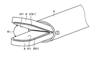
- FIG. 2 is an enlarged view of the distal end portion of the medical treatment apparatus shown in FIG.
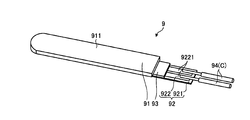
- FIG. 3 is a diagram showing the therapeutic energy application structure shown in FIG.
- FIG. 4 is a diagram showing the therapeutic energy application structure shown in FIG.
- FIG. 5 is a side view showing the flexible substrate shown in FIGS. 3 and 4.
- FIG. 6 is a diagram illustrating a positional relationship between the heat transfer plate, the flexible substrate, and the adhesive sheet illustrated in FIGS. 3 to 5.
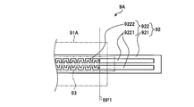
- FIG. 7 is a diagram showing a part of the therapeutic energy application structure according to Embodiment 2 of the present invention.
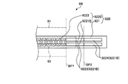
- FIG. 8 is a diagram showing a part of the therapeutic energy application structure according to Embodiment 3 of the present invention.
- FIG. 9 is a side view showing a flexible substrate constituting the therapeutic energy application structure according to Embodiment 4 of the present invention.
- FIG. 10 is a side view showing a flexible substrate constituting the therapeutic energy application structure according to Embodiment 5 of the present invention.
- FIG. 11 is a side view showing a therapeutic energy application structure according to Embodiment 6 of the present invention.
- FIG. 12 is a diagram showing a modification of the sixth embodiment of the present invention.
- FIG. 1 is a diagram schematically showing a medical treatment system 1 according to Embodiment 1 of the present invention.
- the medical treatment system 1 applies energy to a living tissue that is a treatment target, and treats (joins (or anastomoses), separates, etc.) the living tissue.
- the medical treatment system 1 includes a medical treatment device 2, a control device 3, and a foot switch 4.
- the medical treatment device 2 is, for example, a linear type surgical treatment tool for performing treatment on a living tissue through an abdominal wall.
- the medical treatment apparatus 2 includes a handle 5, a shaft 6, and a clamping unit 7.
- the handle 5 is a portion that the operator holds.
- the handle 5 is provided with an operation knob 51 as shown in FIG.
- the shaft 6 has a substantially cylindrical shape, and one end is connected to the handle 5.
- a clamping part 7 is attached to the other end of the shaft 6.
- an opening / closing mechanism (not shown) that opens and closes the holding members 8, 8 ′ (FIG. 1) constituting the holding portion 7 according to the operation of the operation knob 51 by the operator is provided inside the shaft 6.
- an electric cable C (FIG. 1) connected to the control device 3 is disposed inside the shaft 6 from one end side to the other end side via the handle 5.
- FIG. 2 is an enlarged view of the distal end portion of the medical treatment apparatus 2.
- the clamping part 7 is a part which clamps a biological tissue and treats the said biological tissue.
- the clamping unit 7 includes a pair of holding members 8 and 8 ′.
- the pair of holding members 8 and 8 ′ are pivotally supported on the other end of the shaft 6 so as to be openable and closable in the direction of the arrow R 1 (FIG. 2), and can hold the living tissue according to the operation of the operation knob 51 by the operator.
- the pair of holding members 8 and 8 ' are provided with therapeutic energy application structures 9 and 9', respectively, as shown in FIG. Since the therapeutic energy application structures 9 and 9 ′ have the same configuration, only the therapeutic energy application structure 9 will be described below.
- FIG. 3 is a perspective view of the therapeutic energy application structure 9 as viewed from above in FIG.
- FIG. 4 is an exploded perspective view of FIG.
- the therapeutic energy application structure 9 is attached to the upper surface of the holding member 8 disposed on the lower side in FIGS. 1 and 2.
- the therapeutic energy application structure 9 applies thermal energy to the living tissue under the control of the control device 3.
- the therapeutic energy application structure 9 includes a heat transfer plate 91, a flexible substrate 92, an adhesive sheet 93, and two lead wires 94.
- the heat transfer plate 91 is a thin plate (elongated in the left-right direction in FIGS. 3 and 4) made of a material such as copper, and the therapeutic energy application structure 9 is attached to the holding member 8.
- the treatment surface 911 which is one plate surface faces the holding member 8 ′ side (the upper side in FIGS. 1 and 2).
- the heat transfer plate 91 is in contact with the living tissue, and transfers heat from the flexible substrate 92 to the living tissue (heat). Energy is applied to living tissue).
- FIG. 5 is a side view showing the flexible substrate 92.
- a part of the flexible substrate 92 generates heat and functions as a sheet heater that heats the heat transfer plate 91 by the generated heat.
- the flexible substrate 92 includes an insulating substrate 921 and a wiring pattern 922.
- the insulating substrate 921 is a long sheet (long shape extending in the left-right direction in FIGS. 3 to 5) made of polyimide which is an insulating material.
- the material of the insulating substrate 921 is not limited to polyimide, and for example, a highly heat-resistant insulating material such as aluminum nitride, alumina, glass, zirconia, or the like may be employed.
- the width dimension of the insulating substrate 921 is set to be shorter than the width dimension of the heat transfer plate 91.
- the length dimension of the insulating substrate 921 (the length dimension in the left-right direction in FIGS. 3 to 5) is the length dimension of the heat transfer plate 91 (the length dimension in the left-right direction in FIGS. 3 and 4). Is set to be longer.
- the wiring pattern 922 is obtained by processing stainless steel (SUS304), which is a conductive material, and as shown in FIGS. 3 to 5, a pair of lead wire connecting portions 9221 and an electric resistance pattern 9222 (FIGS. 4 and 5). ).
- the wiring pattern 922 is bonded to one surface of the insulating substrate 921 by thermocompression bonding.
- the material of the wiring pattern 922 is not limited to stainless steel (SUS304), and other stainless steel materials (for example, No. 400 series) may be used, or a conductive material such as platinum or tungsten may be adopted.
- the wiring pattern 922 is not limited to a configuration in which the wiring pattern 922 is bonded to one surface of the insulating substrate 921 by thermocompression bonding, and a configuration formed by vapor deposition or the like on the one surface may be employed.
- the pair of lead wire connecting portions 9221 has a function as a connecting portion according to the present invention, and is provided so as to face each other along the width direction of the insulating substrate 921 as shown in FIG. 3 or FIG. Yes.
- the two lead wires 94 (FIGS. 3 and 4) constituting the electric cable C are joined (connected) to the pair of lead wire connecting portions 9221, respectively.
- One end of the electric resistance pattern 9222 is connected (conducted) to one lead wire connecting portion 9221, and from one end to the U-shape following the outer edge shape of the insulating substrate 921, meandering in a wavy shape with a constant line width.
- the other end is connected (conductive) to the other lead wire connecting portion 9221.
- the electrical resistance pattern 9222 generates heat when a voltage is applied (energized) to the pair of lead wire connecting portions 9221 by the control device 3 via the two lead wires 94.
- the thickness dimension of the pair of lead wire connecting portions 9221 is formed to be larger than the thickness dimension of the electric resistance pattern 9222 as shown in FIG. That is, the pair of lead wire connection portions 9221 has a thickness dimension larger than that of the electrical resistance pattern 9222, and thus has an electrical resistance value lower than that of the electrical resistance pattern 9222.
- Such a wiring pattern 922 is manufactured by, for example, forming a relatively large uniform thickness dimension of the entire wiring pattern and then etching the electrical resistance pattern portion to reduce the thickness dimension of the portion. can do.
- a boundary position between the pair of lead wire connection portions 9221 and the electric resistance pattern 9222 (a step portion depending on the thickness of the pair of lead wire connection portions 9221 and the electric resistance pattern 9222) is defined as a boundary position BP1 (FIG. 5).
- the adhesive sheet 93 is interposed between the heat transfer plate 91 and the flexible substrate 92, and the heat transfer plate with a part of the flexible substrate 92 protruding from the heat transfer plate 91.
- the surface opposite to the treatment surface 911 in 91 and one surface of the flexible substrate 92 (surface on the wiring pattern 922 side) are bonded and fixed.
- This adhesive sheet 93 is a long sheet having a good thermal conductivity and insulation, withstanding high temperatures, and having an adhesive property (long shape extending in the left-right direction in FIGS. 3 and 4).
- the width dimension of the adhesive sheet 93 is set to be substantially the same as the width dimension of the insulating substrate 921. Further, the length dimension of the adhesive sheet 93 (the length dimension in the left-right direction in FIGS. 3 and 4) is greater than the length dimension of the heat transfer plate 91 (the length dimension in the left-right direction in FIGS. 3 and 4). The length of the insulating substrate 921 is set to be shorter than the length of the insulating substrate 921 (the length in the horizontal direction in FIGS. 3 to 5).
- FIG. 6 is a diagram showing a positional relationship between the heat transfer plate 91, the flexible substrate 92, and the adhesive sheet 93.
- the base end side (right side in FIGS. 3 and 4) of the therapeutic energy application structure 9 is the treatment surface 911 side (upper side in FIGS. 3 and 4 (thickness direction of the heat transfer plate 91). It is the figure seen from)).
- the heat transfer plate 91 is indicated by a one-dot chain line
- the adhesive sheet 93 is indicated by a two-dot chain line.
- the heat transfer plate 91 covers the entire region of the electric resistance pattern 9222, and one end in the longitudinal direction (the end on the right side in FIGS. 3, 4, and 6) is a pair of lead wires.
- the portion 9221 and the electric resistance pattern 9222 are arranged to coincide with the boundary position BP1.
- the adhesive sheet 93 is disposed so as to cover the entire region of the electric resistance pattern 9222 and to cover a part of the pair of lead wire connection portions 9221. That is, one end side in the longitudinal direction of the adhesive sheet 93 (on the right side in FIGS.
- the foot switch 4 is a part operated by the operator with his / her foot. Then, according to the operation on the foot switch 4, on / off of energization from the control device 3 to the medical treatment device 2 (electrical resistance pattern 9222) is switched. Note that the means for switching on and off is not limited to the foot switch 4, and other switches that are operated by hand may be employed.
- the control device 3 includes a CPU (Central Processing Unit) and the like, and comprehensively controls the operation of the medical treatment device 2 according to a predetermined control program.
- CPU Central Processing Unit
- control device 3 applies a voltage to the electric resistance pattern 9222 via the electric cable C (two lead wires 94) in response to an operation to the foot switch 4 by the operator (operation to turn on energization). Then, the heat transfer plate 91 is heated.
- the thickness dimension of the pair of lead wire connecting portions 9221 is larger than the thickness dimension of the electric resistance pattern 9222.
- the heat transfer plate 91 covers the entire area of the electric resistance pattern 9222 and is arranged so that one end in the longitudinal direction coincides with the boundary position BP1 between the pair of lead wire connecting portions 9221 and the electric resistance pattern 9222.
- the wiring pattern 922 is energized via the two lead wires 94, the vicinity of the boundary position BP1 in the pair of lead wire connection portions 9221 is likely to be overheated.
- the pair of lead wire connection portions 9221 has a thickness dimension larger than that of the electrical resistance pattern 9222, and thus has an electrical resistance value lower than that of the electrical resistance pattern 9222. For this reason, heat_generation
- the heat dissipation effect to the lead wire connecting portion 9221 is further enhanced. From the above, according to the therapeutic energy application structure 9 according to the first embodiment, it is possible to avoid the pair of lead wire connecting portions 9221 from being overheated.
- the adhesive sheet 93 covers the entire region of the electric resistance pattern 9222, and a part of the adhesive sheet 93 protrudes toward the pair of lead wire connection portions 9221 to make a pair of leads. A part of the line connection portion 9221 is covered. That is, the adhesive sheet 93 is disposed so as to straddle the boundary position BP1 between the pair of lead wire connection portions 9221 and the electric resistance pattern 9222. For this reason, the heat
- the medical treatment system according to the second embodiment differs from the medical treatment system 1 described in the first embodiment in the configuration of the therapeutic energy application structures 9 and 9 ′.
- each of the therapeutic energy application structures provided on the holding members 8 and 8 ' has the same configuration. For this reason, below, only the treatment energy provision structure provided in the holding member 8 is demonstrated.
- FIG. 7 is a diagram showing a part of the therapeutic energy application structure 9A according to Embodiment 2 of the present invention. Specifically, FIG. 7 corresponds to FIG.
- the treatment energy application structure 9A according to the second embodiment as shown in FIG. 7, the treatment energy application structure 9 (FIGS. 3, 4, and 6) described in the first embodiment described above is used.
- the heat transfer plate 91A is different from the heat transfer plate 91 in length (length in the left-right direction in FIG. 7).
- the heat transfer plate 91 ⁇ / b> A is set so that the length dimension (the length dimension in the left-right direction in FIG. 7) is longer than that of the heat transfer plate 91.
- FIG. 7 is a diagram showing a part of the therapeutic energy application structure 9A according to Embodiment 2 of the present invention. Specifically, FIG. 7 corresponds to FIG.
- the treatment energy application structure 9 FIG. 7, the treatment energy application structure 9 (FIGS. 3, 4, and 6) described in the first embodiment described above is used.
- the heat transfer plate 91 ⁇ / b> A is disposed so as to cover the entire region of the electric resistance pattern 9222 and to cover a part of the pair of lead wire connection portions 9221. That is, the heat transfer plate 91 ⁇ / b> A is disposed so as to straddle the boundary position BP ⁇ b> 1 between the pair of lead wire connection portions 9221 and the electric resistance pattern 9222. Further, the positional relationship of the adhesive sheet 93 with respect to the pair of lead wire connecting portions 9221 and the electric resistance pattern 9222 is the same as that of the first embodiment described above, as shown in FIG.
- the medical treatment system according to the third embodiment differs from the medical treatment system 1 described in the first embodiment in the configuration of the therapeutic energy application structures 9 and 9 ′.
- the therapeutic energy application structures provided on the holding members 8 and 8 ' have the same configuration. For this reason, below, only the treatment energy provision structure provided in the holding member 8 is demonstrated.
- FIG. 8 is a diagram showing a part of the therapeutic energy application structure 9B according to Embodiment 3 of the present invention. Specifically, FIG. 8 corresponds to FIG.
- the treatment energy application structure 9 (FIGS. 3, 4, and 6) described in the first embodiment is used.
- a flexible substrate 92B having a wiring pattern 922B having a shape different from that of the wiring pattern 922 is employed.
- the wiring pattern 922 ⁇ / b> B has a pair of lead wire connection portions 9221 ⁇ / b> B each having a different shape from the pair of lead wire connection portions 9221.
- the whole is formed to have a thickness dimension larger than the thickness dimension of the electric resistance pattern 9222. That is, the stepped portion due to the thickness of the pair of lead wire connecting portions 9221 and the electric resistance pattern 9222 coincided with the boundary position BP1.
- the pair of lead wire connection portions 9221B according to the third embodiment is formed so that only a part thereof has a thickness dimension larger than the thickness dimension of the electric resistance pattern 9222.
- the pair of lead wire connecting portions 9221B is connected to the electric resistance pattern 9222, and has a small thickness portion 9223 having the same thickness as the electric resistance pattern 9222, and a proximal end side of the small thickness portion 9223 (see FIG. 8, and a large thickness portion 9224 having a thickness dimension larger than that of the small thickness portion 9223. That is, a step portion (boundary position BP2 between the small thickness portion 9223 and the large thickness portion 9224 (FIG. 8)) due to the thickness of the small thickness portion 9223 and the large thickness portion 9224 is a pair of lead wire connection portions 9221 and an electric resistance pattern 9222. Is located closer to the base end side (right side in FIG. 8) than the boundary position BP1.
- the pair of lead wire connecting portions 9221B described above since the large thickness portion 9224 having a thickness dimension larger than that of the electric resistance pattern 9222 is provided, similarly to the first embodiment described above.
- the pair of lead wire connection portions 9221 ⁇ / b> B have a lower electrical resistance value than the electrical resistance pattern 9222.
- the medical treatment system according to the fourth embodiment is different from the medical treatment system 1 described in the first embodiment in the configuration of the therapeutic energy application structures 9 and 9 ′.
- each of the therapeutic energy application structures provided on the holding members 8 and 8 ' has the same configuration. For this reason, below, only the treatment energy provision structure provided in the holding member 8 is demonstrated.
- FIG. 9 is a side view of a flexible substrate 92C constituting the therapeutic energy application structure 9C according to Embodiment 4 of the present invention.
- the treatment energy application structure 9C according to the fourth embodiment as shown in FIG. 9, the treatment energy application structure 9 (FIGS. 3, 4, and 6) described in the first embodiment described above is used.
- a flexible substrate 92C having a wiring pattern 922C having a shape different from that of the wiring pattern 922 and having a pair of conductive layers 923 added thereto is employed.
- the wiring pattern 922 ⁇ / b> C has a pair of lead wire connection portions 9221 ⁇ / b> C each having a different shape from the pair of lead wire connection portions 9221.
- the pair of lead wire connecting portions 9221 ⁇ / b> C are formed to have the same thickness as the electric resistance pattern 9222.
- the pair of conductive layers 923 is a layer made of a conductive material such as gold, silver, copper, or nickel, and formed on the entire surface of the pair of lead wire connection portions 9221C by plating or electroforming. Then, two lead wires 94 (FIGS. 3 and 4) are joined (connected) to the pair of conductive layers 923, respectively.
- the pair of lead wire connecting portions 9221C corresponds to the connecting portion main body according to the present invention
- the pair of conductive layers 923 corresponds to the conductive portion according to the present invention
- the pair of lead wire connection portions 9221C and the pair of conductive layers 923 correspond to the connection portions according to the present invention. That is, the pair of lead wire connection portions 9221C and the pair of conductive layers 923 corresponding to the connection portions according to the present invention are larger than the thickness of the pair of conductive layers 923 by the thickness of the pair of conductive layers 923. Compared to 9222, the electrical resistance value is low.
- the pair of conductive layers 923 is formed on the entire surface of the pair of lead wire connection portions 9221 ⁇ / b> C.
- the present invention is not limited thereto, and is similar to the large thickness portion 9224 described in Embodiment 3 above.
- the pair of conductive layers 923 may be formed only on part of the pair of lead wire connection portions 9221.
- the illustration of the heat transfer plate 91 and the adhesive sheet 93 is omitted, but the positional relationship of the heat transfer plate 91 and the adhesive sheet 93 with respect to the boundary position BP1 between the pair of lead wire connecting portions 9221C and the electric resistance pattern 9222 is as follows. This is the same as in the first embodiment described above.
- the heat transfer plate 91 may be disposed so as to straddle the boundary position BP1 as in the second embodiment.
- a pair of conductive layers 923 are provided on the pair of lead wire connection portions 9221C, and the pair of lead wire connection portions 9221C and the pair of conductive layers 923 are provided. Since the overall thickness dimension is larger than the thickness dimension of the electrical resistance pattern 9222, the same effects as those of the first embodiment described above can be obtained.
- FIG. 10 is a side view of a flexible substrate 92D constituting the therapeutic energy application structure 9D according to Embodiment 5 of the present invention.
- the treatment energy application structure 9D according to the fifth embodiment as shown in FIG. 10, the treatment energy application structure 9 (FIGS. 3, 4, and 6) described in the first embodiment described above is used.
- a flexible substrate 92D having the wiring pattern 922C described in the fourth embodiment and having a pair of first conductive portions 924 and a pair of insulating portions 925 added thereto is employed.
- the pair of insulating portions 925 are plate bodies made of an insulating material such as polyimide.
- the pair of first conductive portions 924 is a plate body made of a conductive material such as copper, and is attached to one plate surface of the pair of insulating portions 925.
- the pair of first conductive portions 924 and the pair of insulating portions 925 have substantially the same planar shape as that of the pair of lead wire connection portions 9221C, but with respect to the pair of lead wire connection portions 9221C.
- the base end side (right side in FIG. 10) is shorter than the pair of lead wire connecting portions 9221C.
- the pair of insulating portions 925 to which the pair of first conductive portions 924 are attached are diffusion bonded and ultrasonic welded with the pair of first conductive portions 924 facing the pair of lead wire connecting portions 9221C. Bonded by resistance welding or the like.
- the pair of conductive layers 923 described in Embodiment 4 described above are interposed between the pair of first conductive portions 924 and the pair of lead wire connection portions 9221C as necessary. Alternatively, it may be firmly bonded by interposing solder, a conductive adhesive or the like.
- a pair of lead wire connection part 9221C is equivalent to the connection part main body which concerns on this invention
- a pair of 1st electroconductive part 924 is equivalent to the electroconductive part which concerns on this invention.
- the pair of lead wire connection portions 9221C and the pair of first conductive portions 924 correspond to the connection portions according to the present invention. That is, the pair of lead wire connection portions 9221C and the pair of first conductive portions 924 corresponding to the connection portions according to the present invention are larger than the thickness of the pair of first conductive portions 924 and the electric resistance pattern 9222. The electric resistance value is lower than that of the electric resistance pattern 9222.
- the positional relationship between the heat transfer plate 91 and the adhesive sheet 93 with respect to the boundary position BP1 between the pair of lead wire connection portions 9221C and the electric resistance pattern 9222 is as follows. This is the same as in the first embodiment described above. Further, as the positional relationship of the heat transfer plate 91 with respect to the boundary position BP1, the heat transfer plate 91 may be disposed so as to straddle the boundary position BP1 as in the second embodiment.
- the pair of first conductive portions 924 are provided on the pair of lead wire connecting portions 9221C, respectively, and the pair of lead wire connecting portions 9221C and the pair of first first electrodes are provided. Since the overall thickness dimension of the conductive portion 924 is larger than the thickness dimension of the electrical resistance pattern 9222, the same effects as those of the first embodiment described above can be obtained. In addition, since the pair of insulating portions 925 are attached to the pair of first conductive portions 924, the insulating treatment of the pair of lead wire connecting portions 9221C at the time of manufacturing the therapeutic energy application structure 9D can be omitted. it can.
- the medical treatment system according to the sixth embodiment differs from the medical treatment system 1 described in the first embodiment in the configuration of the therapeutic energy application structures 9 and 9 ′.
- each of the therapeutic energy application structures provided on the holding members 8 and 8 ' has the same configuration. For this reason, below, only the treatment energy provision structure provided in the holding member 8 is demonstrated.
- FIG. 11 is a side view showing a therapeutic energy application structure 9E according to Embodiment 6 of the present invention.
- the treatment energy application structure 9 (FIGS. 3, 4, and 6) described in the first embodiment is used.
- the second conductive portion 926 is an adhesive sheet similar to the adhesive sheet 93, and is bonded to the pair of lead wire connection portions 9221C across the pair of lead wire connection portions 9221C.
- the two lead wires 94 (FIG. 3, FIG. 3) are exposed to the outside of the pair of lead wire connection portions 9221C (the region on the base end side (right side in FIG. 11) not covered with the second conductive portion 926). 4) are joined together.
- the pair of lead wire connecting portions 9221C corresponds to the connecting portion main body according to the present invention
- the second conductive portion 926 corresponds to the conductive portion according to the present invention
- the pair of lead wire connection portions 9221C and the second conductive portion 926 correspond to the connection portions according to the present invention. That is, the pair of lead wire connection portions 9221C and the second conductive portion 926 corresponding to the connection portions according to the present invention are larger than the thickness of the electric resistance pattern 9222 by the thickness of the second conductive portion 926. Compared to 9222, the electrical resistance value is low.
- the positional relationship between the heat transfer plate 91 and the adhesive sheet 93 with respect to the boundary position BP1 between the pair of lead wire connection portions 9221 and the electric resistance pattern 9222 is the same as that in the first embodiment described above, as shown in FIG.
- the adhesive sheet 93 is disposed in a state where one end in the longitudinal direction (the right end in FIG. 11) is spaced from the second conductive portion 926.
- the heat transfer plate 91 may be disposed so as to straddle the boundary position BP1 as in the second embodiment.
- the second conductive portion 926 is provided on the pair of lead wire connecting portions 9221C, and the entire pair of lead wire connecting portions 9221C and the second conductive portion 926 is provided. Since the thickness dimension is larger than the thickness dimension of the electric resistance pattern 9222, the same effects as those of the first embodiment described above can be obtained. In addition, since the second conductive portion 926 is disposed in a state of being separated from the adhesive sheet 93, the heat transmitted from the wiring pattern 922C to the adhesive sheet 93 is not transmitted to the second conductive portion 926. That is, the second conductive portion 926 can effectively dissipate heat from the pair of lead wire connection portions 9221C.
- FIG. 12 is a diagram showing a modification of the sixth embodiment of the present invention. Specifically, FIG. 12 corresponds to FIG. Instead of the therapeutic energy application structure 9E described in the sixth embodiment, the therapeutic energy application structure 9F shown in FIG. 12 may be employed. Specifically, as shown in FIG. 12, the therapeutic energy application structure 9 ⁇ / b> F has a heat sink made of a metal such as aluminum, copper, or iron, or a high thermal conductive ceramic such as aluminum nitride on the upper surface of the second conductive portion 926. 95 is joined.
- a heat sink made of a metal such as aluminum, copper, or iron, or a high thermal conductive ceramic such as aluminum nitride on the upper surface of the second conductive portion 926. 95 is joined.
- a coating having a heat dissipation effect may be applied to the upper surface of the second conductive portion 926.
- the coating include DLC (Diamond-Like Carbon) and alumina, or a coating material with high emissivity, an alumite treatment, and the like.
- the second conductive portion 926 may be omitted, and the above-described coating may be performed on the pair of lead wire connection portions 9221C.
- the present invention should not be limited only by the above-described first to sixth embodiments and the modifications of the sixth embodiment.
- the therapeutic energy application structures 9 (9 ′) and 9A to 9F are provided on both the holding members 8 and 8 ′, respectively.
- the present invention is not limited to this, and a configuration in which only one of the holding members 8 and 8 ′ is provided may be employed.
- the therapeutic energy application structures 9 (9 ′) and 9A to 9F are configured to apply thermal energy to the living tissue.
- the present invention is not limited to this, and may be configured to apply high-frequency energy or ultrasonic energy in addition to thermal energy.
Landscapes
- Health & Medical Sciences (AREA)
- Surgery (AREA)
- Life Sciences & Earth Sciences (AREA)
- Engineering & Computer Science (AREA)
- Biomedical Technology (AREA)
- Nuclear Medicine, Radiotherapy & Molecular Imaging (AREA)
- Heart & Thoracic Surgery (AREA)
- Medical Informatics (AREA)
- Molecular Biology (AREA)
- Animal Behavior & Ethology (AREA)
- General Health & Medical Sciences (AREA)
- Public Health (AREA)
- Veterinary Medicine (AREA)
- Otolaryngology (AREA)
- Plasma & Fusion (AREA)
- Physics & Mathematics (AREA)
- Surgical Instruments (AREA)
Abstract
治療用エネルギ付与構造(9)は、絶縁性基板(921)と、絶縁性基板(921)の一方の面に設けられた電気抵抗パターン(9222)と、当該一方の面に設けられ、電気抵抗パターン(9222)に比して電気抵抗値が低い一対のリード線接続部(9221)と、当該一方の面に対向して配設された伝熱板(91)とを備える。絶縁性基板(921)及び伝熱板(91)は、同一の方向に延びる長尺状にそれぞれ形成されている。電気抵抗パターン(9222)及び一対のリード線接続部(9221)は、絶縁性基板(921)の長手方向に沿って並んで配設される。伝熱板(91)は、電気抵抗パターン(9222)の全領域を覆い、当該伝熱板(91)の長手方向の一端が電気抵抗パターン(9222)及び一対のリード線接続部(9221)の境界位置(BP1)に一致する。一対のリード線接続部(9221)の厚み寸法は、電気抵抗パターン(9222)の厚み寸法よりも大きい。
Description
本発明は、治療用エネルギ付与構造及び医療用処置装置に関する。
従来、生体組織にエネルギを付与する治療用エネルギ付与構造が設けられ、当該エネルギの付与により生体組織を処置(接合(若しくは吻合)及び切離等)する医療用処置装置が知られている(例えば、特許文献1参照)。
特許文献1に記載の治療用エネルギ付与構造は、以下に示すフレキシブル基板及び伝熱板を備える。
フレキシブル基板は、シートヒータとして機能する部分である。そして、フレキシブル基板の一方の面には、通電により発熱する電気抵抗パターンと、当該電気抵抗パターンに導通する接続部とが形成されている。
伝熱板は、銅等の導体で構成されている。そして、伝熱板は、フレキシブル基板の一方の面(電気抵抗パターン)に対向して配設され、抵抗パターンからの熱を生体組織に伝達する(熱エネルギを生体組織に付与する)。
ここで、フレキシブル基板は、伝熱板よりも長く、組み立てられた時に、一端側(接続部が設けられた側)が伝熱板から突出する。そして、当該一端側に設けられた接続部には、電気抵抗パターンに電力を供給するリード線が接続される。すなわち、特許文献1に記載の治療用エネルギ付与構造では、リード線をフレキシブル基板の一方の面(伝熱板が配設される側)に位置付けることにより、薄型化を図っている。
特許文献1に記載の治療用エネルギ付与構造は、以下に示すフレキシブル基板及び伝熱板を備える。
フレキシブル基板は、シートヒータとして機能する部分である。そして、フレキシブル基板の一方の面には、通電により発熱する電気抵抗パターンと、当該電気抵抗パターンに導通する接続部とが形成されている。
伝熱板は、銅等の導体で構成されている。そして、伝熱板は、フレキシブル基板の一方の面(電気抵抗パターン)に対向して配設され、抵抗パターンからの熱を生体組織に伝達する(熱エネルギを生体組織に付与する)。
ここで、フレキシブル基板は、伝熱板よりも長く、組み立てられた時に、一端側(接続部が設けられた側)が伝熱板から突出する。そして、当該一端側に設けられた接続部には、電気抵抗パターンに電力を供給するリード線が接続される。すなわち、特許文献1に記載の治療用エネルギ付与構造では、リード線をフレキシブル基板の一方の面(伝熱板が配設される側)に位置付けることにより、薄型化を図っている。
ところで、特許文献1に記載の治療用エネルギ付与構造では、伝熱板の温度を一定に保つ制御を行う際、例えば、水分が多い等で熱容量が極端に大きい臓器での処置や、血中等の放熱し易い環境での処置の場合には、伝熱板の温度を保つためにリード線を介して接続部(電気抵抗パターン)に大きい電力を加えることとなる。そして、このように大きい電力を接続部に加えた場合には、本来は加熱する意図のない接続部が過加熱状態となってしまう恐れがある。
本発明は、上記に鑑みてなされたものであって、接続部が過加熱状態となってしまうことを回避することができる治療用エネルギ付与構造及び医療用処置装置を提供することを目的とする。
上述した課題を解決し、目的を達成するために、本発明に係る治療用エネルギ付与構造は、絶縁性基板と、前記絶縁性基板の一方の面に設けられ、通電により発熱する電気抵抗パターンと、前記一方の面に設けられ、前記電気抵抗パターンに導通するとともに、前記電気抵抗パターンに比して電気抵抗値が低い接続部と、前記一方の面に対向して配設され、前記電気抵抗パターンからの熱を生体組織に伝達する伝熱板と、を備え、前記絶縁性基板及び前記伝熱板は、同一の方向に延びる長尺状にそれぞれ形成され、前記電気抵抗パターン及び前記接続部は、前記絶縁性基板の長手方向に沿って並んで配設され、前記伝熱板は、当該伝熱板の厚み方向から見て、前記電気抵抗パターンの全領域を覆い、当該伝熱板の長手方向の一端が前記電気抵抗パターン及び前記接続部の境界位置に一致する、または、当該一端が当該境界位置よりも前記接続部側に位置し、前記接続部の少なくとも一部の厚み寸法は、前記電気抵抗パターンの厚み寸法よりも大きいことを特徴とする。
また、本発明に係る医療用処置装置は、上述した治療用エネルギ付与構造を備えることを特徴とする。
また、本発明に係る医療用処置装置は、上述した治療用エネルギ付与構造を備えることを特徴とする。
本発明に係る治療用エネルギ付与構造及び医療用処置装置によれば、接続部が過加熱状態となってしまうことを回避することができる、という効果を奏する。
以下に、図面を参照して、本発明を実施するための形態(以下、実施の形態)について説明する。なお、以下に説明する実施の形態によって本発明が限定されるものではない。さらに、図面の記載において、同一の部分には同一の符号を付している。
(実施の形態1)
〔医療用処置システムの概略構成〕
図1は、本発明の実施の形態1に係る医療用処置システム1を模式的に示す図である。
医療用処置システム1は、処置対象である生体組織にエネルギを付与し、当該生体組織を処置(接合(若しくは吻合)及び切離等)する。この医療用処置システム1は、図1に示すように、医療用処置装置2と、制御装置3と、フットスイッチ4とを備える。
〔医療用処置システムの概略構成〕
図1は、本発明の実施の形態1に係る医療用処置システム1を模式的に示す図である。
医療用処置システム1は、処置対象である生体組織にエネルギを付与し、当該生体組織を処置(接合(若しくは吻合)及び切離等)する。この医療用処置システム1は、図1に示すように、医療用処置装置2と、制御装置3と、フットスイッチ4とを備える。
〔医療用処置装置の構成〕
医療用処置装置2は、例えば、腹壁を通して生体組織に処置を行うためのリニアタイプの外科医療用処置具である。この医療用処置装置2は、図1に示すように、ハンドル5と、シャフト6と、挟持部7とを備える。
ハンドル5は、術者が把持する部分である。そして、このハンドル5には、図1に示すように、操作ノブ51が設けられている。
シャフト6は、図1に示すように、略円筒形状を有し、一端がハンドル5に接続されている。また、シャフト6の他端には、挟持部7が取り付けられている。そして、このシャフト6の内部には、術者による操作ノブ51の操作に応じて、挟持部7を構成する保持部材8,8´(図1)を開閉させる開閉機構(図示略)が設けられている。また、このシャフト6の内部には、制御装置3に接続された電気ケーブルC(図1)がハンドル5を介して一端側から他端側まで配設されている。
医療用処置装置2は、例えば、腹壁を通して生体組織に処置を行うためのリニアタイプの外科医療用処置具である。この医療用処置装置2は、図1に示すように、ハンドル5と、シャフト6と、挟持部7とを備える。
ハンドル5は、術者が把持する部分である。そして、このハンドル5には、図1に示すように、操作ノブ51が設けられている。
シャフト6は、図1に示すように、略円筒形状を有し、一端がハンドル5に接続されている。また、シャフト6の他端には、挟持部7が取り付けられている。そして、このシャフト6の内部には、術者による操作ノブ51の操作に応じて、挟持部7を構成する保持部材8,8´(図1)を開閉させる開閉機構(図示略)が設けられている。また、このシャフト6の内部には、制御装置3に接続された電気ケーブルC(図1)がハンドル5を介して一端側から他端側まで配設されている。
〔挟持部の構成〕
図2は、医療用処置装置2の先端部分を拡大した図である。
なお、図1及び図2において、「´」が付加されていない符号が示す構成と「´」が付加された符号が示す構成とは、同一の構成である。以降の図も同様である。
挟持部7は、生体組織を挟持して、当該生体組織を処置する部分である。この挟持部7は、図1または図2に示すように、一対の保持部材8,8´を備える。
一対の保持部材8,8´は、矢印R1(図2)方向に開閉可能にシャフト6の他端に軸支され、術者による操作ノブ51の操作に応じて、生体組織を挟持可能とする。
そして、一対の保持部材8,8´には、図2に示すように、治療用エネルギ付与構造9,9´がそれぞれ設けられている。
治療用エネルギ付与構造9,9´が同一の構成を有しているため、以下では、治療用エネルギ付与構造9のみを説明する。
図2は、医療用処置装置2の先端部分を拡大した図である。
なお、図1及び図2において、「´」が付加されていない符号が示す構成と「´」が付加された符号が示す構成とは、同一の構成である。以降の図も同様である。
挟持部7は、生体組織を挟持して、当該生体組織を処置する部分である。この挟持部7は、図1または図2に示すように、一対の保持部材8,8´を備える。
一対の保持部材8,8´は、矢印R1(図2)方向に開閉可能にシャフト6の他端に軸支され、術者による操作ノブ51の操作に応じて、生体組織を挟持可能とする。
そして、一対の保持部材8,8´には、図2に示すように、治療用エネルギ付与構造9,9´がそれぞれ設けられている。
治療用エネルギ付与構造9,9´が同一の構成を有しているため、以下では、治療用エネルギ付与構造9のみを説明する。
〔治療用エネルギ付与構造の構成〕
図3及び図4は、治療用エネルギ付与構造9を示す図である。具体的に、図3は、図2中、上方側から治療用エネルギ付与構造9を見た斜視図である。図4は、図3の分解斜視図である。
治療用エネルギ付与構造9は、図1及び図2中、下方側に配設された保持部材8における上方側の面に取り付けられている。そして、治療用エネルギ付与構造9は、制御装置3による制御の下、生体組織に対して熱エネルギを付与する。この治療用エネルギ付与構造9は、図3または図4に示すように、伝熱板91と、フレキシブル基板92と、接着シート93と、2つのリード線94とを備える。
図3及び図4は、治療用エネルギ付与構造9を示す図である。具体的に、図3は、図2中、上方側から治療用エネルギ付与構造9を見た斜視図である。図4は、図3の分解斜視図である。
治療用エネルギ付与構造9は、図1及び図2中、下方側に配設された保持部材8における上方側の面に取り付けられている。そして、治療用エネルギ付与構造9は、制御装置3による制御の下、生体組織に対して熱エネルギを付与する。この治療用エネルギ付与構造9は、図3または図4に示すように、伝熱板91と、フレキシブル基板92と、接着シート93と、2つのリード線94とを備える。
伝熱板91は、例えば銅等の材料で構成された長尺状(図3及び図4中、左右方向に延びる長尺状)の薄板であり、治療用エネルギ付与構造9が保持部材8に取り付けられた状態で、一方の板面である処置面911が保持部材8´側(図1及び図2中、上方側)を向く。そして、伝熱板91は、保持部材8,8´にて生体組織を挟持した状態で、処置面911が当該生体組織に接触し、フレキシブル基板92からの熱を当該生体組織に伝達する(熱エネルギを生体組織に付与する)。
図5は、フレキシブル基板92を示す側面図である。
フレキシブル基板92は、一部が発熱し、当該発熱により伝熱板91を加熱するシートヒータとして機能する。このフレキシブル基板92は、図3ないし図5に示すように、絶縁性基板921と、配線パターン922とを備える。
絶縁性基板921は、絶縁性材料であるポリイミドで構成された長尺状(図3ないし図5中、左右方向に延びる長尺状)のシートである。
なお、絶縁性基板921の材料としては、ポリイミドに限られず、例えば、窒化アルミ、アルミナ、ガラス、ジルコニア等の高耐熱絶縁性材料を採用しても構わない。
ここで、絶縁性基板921の幅寸法は、伝熱板91の幅寸法よりも短くなるように設定されている。また、絶縁性基板921の長さ寸法(図3ないし図5中、左右方向の長さ寸法)は、伝熱板91の長さ寸法(図3及び図4中、左右方向の長さ寸法)よりも長くなるように設定されている。
フレキシブル基板92は、一部が発熱し、当該発熱により伝熱板91を加熱するシートヒータとして機能する。このフレキシブル基板92は、図3ないし図5に示すように、絶縁性基板921と、配線パターン922とを備える。
絶縁性基板921は、絶縁性材料であるポリイミドで構成された長尺状(図3ないし図5中、左右方向に延びる長尺状)のシートである。
なお、絶縁性基板921の材料としては、ポリイミドに限られず、例えば、窒化アルミ、アルミナ、ガラス、ジルコニア等の高耐熱絶縁性材料を採用しても構わない。
ここで、絶縁性基板921の幅寸法は、伝熱板91の幅寸法よりも短くなるように設定されている。また、絶縁性基板921の長さ寸法(図3ないし図5中、左右方向の長さ寸法)は、伝熱板91の長さ寸法(図3及び図4中、左右方向の長さ寸法)よりも長くなるように設定されている。
配線パターン922は、導電性材料であるステンレス(SUS304)を加工したものであり、図3ないし図5に示すように、一対のリード線接続部9221と、電気抵抗パターン9222(図4,図5)とを備える。そして、配線パターン922は、絶縁性基板921の一方の面に熱圧着により貼り合わせられる。
なお、配線パターン922の材料としては、ステンレス(SUS304)に限られず、他のステンレス材料(例えば400番系)でもよいし、プラチナや、タングステン等の導電性材料を採用しても構わない。また、配線パターン922としては、絶縁性基板921の一方の面に熱圧着により貼り合わせられる構成に限られず、当該一方の面に蒸着等により形成した構成を採用しても構わない。
なお、配線パターン922の材料としては、ステンレス(SUS304)に限られず、他のステンレス材料(例えば400番系)でもよいし、プラチナや、タングステン等の導電性材料を採用しても構わない。また、配線パターン922としては、絶縁性基板921の一方の面に熱圧着により貼り合わせられる構成に限られず、当該一方の面に蒸着等により形成した構成を採用しても構わない。
一対のリード線接続部9221は、本発明に係る接続部としての機能を有し、図3または図4に示すように、絶縁性基板921の幅方向に沿って互いに対向するように設けられている。そして、一対のリード線接続部9221には、電気ケーブルCを構成する2つのリード線94(図3,図4)がそれぞれ接合(接続)される。
電気抵抗パターン9222は、一端が一方のリード線接続部9221に接続(導通)し、当該一端から、一定の線幅で波状に蛇行しながら、絶縁性基板921の外縁形状に倣うU字形状に沿って延び、他端が他方のリード線接続部9221に接続(導通)する。
そして、電気抵抗パターン9222は、2つのリード線94を介して制御装置3により一対のリード線接続部9221に電圧が印加(通電)されることにより、発熱する。
電気抵抗パターン9222は、一端が一方のリード線接続部9221に接続(導通)し、当該一端から、一定の線幅で波状に蛇行しながら、絶縁性基板921の外縁形状に倣うU字形状に沿って延び、他端が他方のリード線接続部9221に接続(導通)する。
そして、電気抵抗パターン9222は、2つのリード線94を介して制御装置3により一対のリード線接続部9221に電圧が印加(通電)されることにより、発熱する。
以上説明した配線パターン922では、一対のリード線接続部9221の厚み寸法は、図5に示すように、電気抵抗パターン9222の厚み寸法よりも大きくなるように形成されている。すなわち、一対のリード線接続部9221は、厚み寸法が電気抵抗パターン9222の厚み寸法よりも大きいため、電気抵抗パターン9222に比して、電気抵抗値が低くなっている。
このような配線パターン922としては、例えば、配線パターン全体の厚み寸法を比較的に大きく均一に形成した後、電気抵抗パターンの部分にエッチング加工を施して当該部分の厚み寸法を小さくすることで製造することができる。
以下、一対のリード線接続部9221と電気抵抗パターン9222との境界位置(一対のリード線接続部9221と電気抵抗パターン9222との厚みによる段差部分)を境界位置BP1(図5)とする。
このような配線パターン922としては、例えば、配線パターン全体の厚み寸法を比較的に大きく均一に形成した後、電気抵抗パターンの部分にエッチング加工を施して当該部分の厚み寸法を小さくすることで製造することができる。
以下、一対のリード線接続部9221と電気抵抗パターン9222との境界位置(一対のリード線接続部9221と電気抵抗パターン9222との厚みによる段差部分)を境界位置BP1(図5)とする。
接着シート93は、図3または図4に示すように、伝熱板91とフレキシブル基板92との間に介装され、フレキシブル基板92の一部が伝熱板91から張り出した状態で伝熱板91における処置面911とは反対側の面とフレキシブル基板92の一方の面(配線パターン922側の面)とを接着固定する。この接着シート93は、良好な熱伝導性及び絶縁性を有し、かつ、高温に耐え、接着性を有する長尺状(図3及び図4中、左右方向に延びる長尺状)のシートであり、例えば、アルミナ、窒化ホウ素、グラファイト、窒化アルミ等の高熱伝導フィラー(非導電性材料)をエポキシやポリウレタン等の樹脂と混合することにより形成されている。
ここで、接着シート93の幅寸法は、絶縁性基板921の幅寸法と略同一となるように設定されている。また、接着シート93の長さ寸法(図3及び図4中、左右方向の長さ寸法)は、伝熱板91の長さ寸法(図3及び図4中、左右方向の長さ寸法)よりも長く、絶縁性基板921の長さ寸法(図3ないし図5中、左右方向の長さ寸法)よりも短くなるように設定されている。
ここで、接着シート93の幅寸法は、絶縁性基板921の幅寸法と略同一となるように設定されている。また、接着シート93の長さ寸法(図3及び図4中、左右方向の長さ寸法)は、伝熱板91の長さ寸法(図3及び図4中、左右方向の長さ寸法)よりも長く、絶縁性基板921の長さ寸法(図3ないし図5中、左右方向の長さ寸法)よりも短くなるように設定されている。
〔伝熱板、フレキシブル基板、及び接着シートの位置関係〕
次に、上述した伝熱板91、フレキシブル基板92、及び接着シート93の位置関係について図6を参照しつつ説明する。
図6は、伝熱板91、フレキシブル基板92、及び接着シート93の位置関係を示す図である。具体的に、図6は、治療用エネルギ付与構造9における基端側(図3及び図4中、右側)を処置面911側(図3及び図4中、上側(伝熱板91の厚み方向))から見た図である。
なお、図6では、説明の便宜上、伝熱板91を一点鎖線で示し、接着シート93を二点鎖線で示している。
次に、上述した伝熱板91、フレキシブル基板92、及び接着シート93の位置関係について図6を参照しつつ説明する。
図6は、伝熱板91、フレキシブル基板92、及び接着シート93の位置関係を示す図である。具体的に、図6は、治療用エネルギ付与構造9における基端側(図3及び図4中、右側)を処置面911側(図3及び図4中、上側(伝熱板91の厚み方向))から見た図である。
なお、図6では、説明の便宜上、伝熱板91を一点鎖線で示し、接着シート93を二点鎖線で示している。
伝熱板91は、図6に示すように、電気抵抗パターン9222の全領域を覆い、長手方向の一端(図3、図4、及び図6中、右側の端部)が一対のリード線接続部9221及び電気抵抗パターン9222の境界位置BP1に一致するように配置される。
接着シート93は、図6に示すように、電気抵抗パターン9222の全領域を覆うとともに、一対のリード線接続部9221の一部を覆うように配置される。すなわち、接着シート93における長手方向の一端側(図3、図4、及び図6中、右側)は、一対のリード線接続部9221及び電気抵抗パターン9222の境界位置BP1を跨ぎ、伝熱板91に対して図6中、右側に張り出した状態となる。そして、一対のリード線接続部9221における外部に露出した領域(接着シート93にて覆われていない領域)に2つのリード線94(図3,図4)がそれぞれ接合(接続)される。
接着シート93は、図6に示すように、電気抵抗パターン9222の全領域を覆うとともに、一対のリード線接続部9221の一部を覆うように配置される。すなわち、接着シート93における長手方向の一端側(図3、図4、及び図6中、右側)は、一対のリード線接続部9221及び電気抵抗パターン9222の境界位置BP1を跨ぎ、伝熱板91に対して図6中、右側に張り出した状態となる。そして、一対のリード線接続部9221における外部に露出した領域(接着シート93にて覆われていない領域)に2つのリード線94(図3,図4)がそれぞれ接合(接続)される。
〔制御装置及びフットスイッチの構成〕
フットスイッチ4は、術者が足で操作する部分である。そして、フットスイッチ4への当該操作に応じて、制御装置3から医療用処置装置2(電気抵抗パターン9222)への通電のオン及びオフが切り替えられる。
なお、当該オン及びオフを切り替える手段としては、フットスイッチ4に限られず、その他、手で操作するスイッチ等を採用しても構わない。
制御装置3は、CPU(Central Processing Unit)等を含んで構成され、所定の制御プログラムにしたがって、医療用処置装置2の動作を統括的に制御する。より具体的に、制御装置3は、術者によるフットスイッチ4への操作(通電オンの操作)に応じて、電気ケーブルC(2つのリード線94)を介して電気抵抗パターン9222に電圧を印加して、伝熱板91を加熱する。
フットスイッチ4は、術者が足で操作する部分である。そして、フットスイッチ4への当該操作に応じて、制御装置3から医療用処置装置2(電気抵抗パターン9222)への通電のオン及びオフが切り替えられる。
なお、当該オン及びオフを切り替える手段としては、フットスイッチ4に限られず、その他、手で操作するスイッチ等を採用しても構わない。
制御装置3は、CPU(Central Processing Unit)等を含んで構成され、所定の制御プログラムにしたがって、医療用処置装置2の動作を統括的に制御する。より具体的に、制御装置3は、術者によるフットスイッチ4への操作(通電オンの操作)に応じて、電気ケーブルC(2つのリード線94)を介して電気抵抗パターン9222に電圧を印加して、伝熱板91を加熱する。
〔医療用処置装置の動作〕
次に、上述した医療用処置システム1の動作について説明する。
術者は、医療用処置装置2を把持し、医療用処置装置2の先端部分(挟持部7及びシャフト6の一部)を、例えば、トロッカ等を用いて腹壁を通して腹腔内に挿入する。また、術者は、操作ノブ51を操作し、保持部材8,8´にて処置対象の生体組織を挟持する。
次に、術者は、フットスイッチ4を操作し、制御装置3から医療用処置装置2への通電をオンに切り替える。当該オンに切り替えられると、制御装置3は、電気ケーブルC(2つのリード線94)を介して配線パターン922に電圧を印加し、伝熱板91を加熱する。そして、伝熱板91の熱により、伝熱板91に接触している生体組織は処置される。
次に、上述した医療用処置システム1の動作について説明する。
術者は、医療用処置装置2を把持し、医療用処置装置2の先端部分(挟持部7及びシャフト6の一部)を、例えば、トロッカ等を用いて腹壁を通して腹腔内に挿入する。また、術者は、操作ノブ51を操作し、保持部材8,8´にて処置対象の生体組織を挟持する。
次に、術者は、フットスイッチ4を操作し、制御装置3から医療用処置装置2への通電をオンに切り替える。当該オンに切り替えられると、制御装置3は、電気ケーブルC(2つのリード線94)を介して配線パターン922に電圧を印加し、伝熱板91を加熱する。そして、伝熱板91の熱により、伝熱板91に接触している生体組織は処置される。
以上説明した本実施の形態1に係る治療用エネルギ付与構造9では、一対のリード線接続部9221の厚み寸法は、電気抵抗パターン9222の厚み寸法よりも大きい。また、伝熱板91は、電気抵抗パターン9222の全領域を覆い、長手方向の一端が一対のリード線接続部9221及び電気抵抗パターン9222の境界位置BP1に一致するように配置される。
2つのリード線94を介した配線パターン922への通電時には、一対のリード線接続部9221における境界位置BP1付近が過加熱状態となる可能性が高いものである。このため、一対のリード線接続部9221及び電気抵抗パターン9222の厚み関係、並びに、伝熱板91と境界位置BP1との位置関係を上記のように設定することにより、一対のリード線接続部9221における境界位置BP1付近の熱を、接着シート93を介して伝熱板91に放熱し、さらに、リード線接続部9221に放熱することができる。
また、一対のリード線接続部9221は、電気抵抗パターン9222よりも厚み寸法が大きいため、電気抵抗パターン9222に比して、電気抵抗値が低くなっている。このため、一対のリード線接続部9221の発熱自体を抑制することができる。その結果、リード線接続部9221への放熱効果もより一層高まる。
以上のことから、本実施の形態1に係る治療用エネルギ付与構造9によれば、一対のリード線接続部9221が過加熱状態となってしまうことを回避することができる、という効果を奏する。
2つのリード線94を介した配線パターン922への通電時には、一対のリード線接続部9221における境界位置BP1付近が過加熱状態となる可能性が高いものである。このため、一対のリード線接続部9221及び電気抵抗パターン9222の厚み関係、並びに、伝熱板91と境界位置BP1との位置関係を上記のように設定することにより、一対のリード線接続部9221における境界位置BP1付近の熱を、接着シート93を介して伝熱板91に放熱し、さらに、リード線接続部9221に放熱することができる。
また、一対のリード線接続部9221は、電気抵抗パターン9222よりも厚み寸法が大きいため、電気抵抗パターン9222に比して、電気抵抗値が低くなっている。このため、一対のリード線接続部9221の発熱自体を抑制することができる。その結果、リード線接続部9221への放熱効果もより一層高まる。
以上のことから、本実施の形態1に係る治療用エネルギ付与構造9によれば、一対のリード線接続部9221が過加熱状態となってしまうことを回避することができる、という効果を奏する。
また、本実施の形態1に係る治療用エネルギ付与構造9では、接着シート93は、電気抵抗パターン9222の全領域を覆うとともに、一部が一対のリード線接続部9221側に張り出して一対のリード線接続部9221の一部を覆う。すなわち、接着シート93は、一対のリード線接続部9221及び電気抵抗パターン9222の境界位置BP1を跨ぐように配置されている。このため、一対のリード線接続部9221における境界位置BP1付近の熱を接着シート93に放熱することができ、一対のリード線接続部9221の過加熱状態を効果的に回避することができる。
(実施の形態2)
次に、本発明の実施の形態2について説明する。
以下の説明では、上述した実施の形態1と同様の構成には同一符号を付し、その詳細な説明は省略または簡略化する。
本実施の形態2に係る医療用処置システムは、上述した実施の形態1で説明した医療用処置システム1に対して、治療用エネルギ付与構造9,9´の構成が異なる。なお、本実施の形態2において、保持部材8,8´にそれぞれ設けられた各治療用エネルギ付与構造は、同一の構成を有する。このため、以下では、保持部材8に設けられた治療用エネルギ付与構造のみを説明する。
次に、本発明の実施の形態2について説明する。
以下の説明では、上述した実施の形態1と同様の構成には同一符号を付し、その詳細な説明は省略または簡略化する。
本実施の形態2に係る医療用処置システムは、上述した実施の形態1で説明した医療用処置システム1に対して、治療用エネルギ付与構造9,9´の構成が異なる。なお、本実施の形態2において、保持部材8,8´にそれぞれ設けられた各治療用エネルギ付与構造は、同一の構成を有する。このため、以下では、保持部材8に設けられた治療用エネルギ付与構造のみを説明する。
〔治療用エネルギ付与構造の構成〕
図7は、本発明の実施の形態2に係る治療用エネルギ付与構造9Aの一部を示す図である。具体的に、図7は、図6に対応した図である。
本実施の形態2に係る治療用エネルギ付与構造9Aでは、図7に示すように、上述した実施の形態1で説明した治療用エネルギ付与構造9(図3,図4,図6)に対して、伝熱板91とは長さ寸法(図7中、左右方向の長さ寸法)が異なる伝熱板91Aを採用している。
具体的に、伝熱板91Aは、伝熱板91よりも、長さ寸法(図7中、左右方向の長さ寸法)が長くなるように設定されている。そして、伝熱板91Aは、図7に示すように、電気抵抗パターン9222の全領域を覆うとともに、一対のリード線接続部9221の一部を覆うように配置される。すなわち、伝熱板91Aは、一対のリード線接続部9221及び電気抵抗パターン9222の境界位置BP1を跨ぐように配置される。
また、一対のリード線接続部9221及び電気抵抗パターン9222に対する接着シート93の位置関係は、図7に示すように、上述した実施の形態1と同様である。
図7は、本発明の実施の形態2に係る治療用エネルギ付与構造9Aの一部を示す図である。具体的に、図7は、図6に対応した図である。
本実施の形態2に係る治療用エネルギ付与構造9Aでは、図7に示すように、上述した実施の形態1で説明した治療用エネルギ付与構造9(図3,図4,図6)に対して、伝熱板91とは長さ寸法(図7中、左右方向の長さ寸法)が異なる伝熱板91Aを採用している。
具体的に、伝熱板91Aは、伝熱板91よりも、長さ寸法(図7中、左右方向の長さ寸法)が長くなるように設定されている。そして、伝熱板91Aは、図7に示すように、電気抵抗パターン9222の全領域を覆うとともに、一対のリード線接続部9221の一部を覆うように配置される。すなわち、伝熱板91Aは、一対のリード線接続部9221及び電気抵抗パターン9222の境界位置BP1を跨ぐように配置される。
また、一対のリード線接続部9221及び電気抵抗パターン9222に対する接着シート93の位置関係は、図7に示すように、上述した実施の形態1と同様である。
以上説明した本実施の形態2のように一対のリード線接続部9221及び電気抵抗パターン9222の境界位置BP1を跨ぐように伝熱板91Aを配置した場合であっても、一対のリード線接続部9221における境界位置BP1付近の熱を、接着シート93を介して伝熱板91Aに放熱し、さらに、リード線接続部9221に放熱することができるため、上述した実施の形態1と同様の効果を奏する。
(実施の形態3)
次に、本発明の実施の形態3について説明する。
以下の説明では、上述した実施の形態1と同様の構成には同一符号を付し、その詳細な説明は省略または簡略化する。
本実施の形態3に係る医療用処置システムは、上述した実施の形態1で説明した医療用処置システム1に対して、治療用エネルギ付与構造9,9´の構成が異なる。なお、本実施の形態3において、保持部材8,8´にそれぞれ設けられた各治療用エネルギ付与構造は、同一の構成を有する。このため、以下では、保持部材8に設けられた治療用エネルギ付与構造のみを説明する。
次に、本発明の実施の形態3について説明する。
以下の説明では、上述した実施の形態1と同様の構成には同一符号を付し、その詳細な説明は省略または簡略化する。
本実施の形態3に係る医療用処置システムは、上述した実施の形態1で説明した医療用処置システム1に対して、治療用エネルギ付与構造9,9´の構成が異なる。なお、本実施の形態3において、保持部材8,8´にそれぞれ設けられた各治療用エネルギ付与構造は、同一の構成を有する。このため、以下では、保持部材8に設けられた治療用エネルギ付与構造のみを説明する。
〔治療用エネルギ付与構造の構成〕
図8は、本発明の実施の形態3に係る治療用エネルギ付与構造9Bの一部を示す図である。具体的に、図8は、図6に対応した図である。
本実施の形態3に係る治療用エネルギ付与構造9Bでは、図8に示すように、上述した実施の形態1で説明した治療用エネルギ付与構造9(図3,図4,図6)に対して、配線パターン922とは異なる形状の配線パターン922Bを有するフレキシブル基板92Bを採用している。
図8は、本発明の実施の形態3に係る治療用エネルギ付与構造9Bの一部を示す図である。具体的に、図8は、図6に対応した図である。
本実施の形態3に係る治療用エネルギ付与構造9Bでは、図8に示すように、上述した実施の形態1で説明した治療用エネルギ付与構造9(図3,図4,図6)に対して、配線パターン922とは異なる形状の配線パターン922Bを有するフレキシブル基板92Bを採用している。
具体的に、配線パターン922Bは、一対のリード線接続部9221とはそれぞれ異なる形状の一対のリード線接続部9221Bを有する。
上述した実施の形態1で説明した一対のリード線接続部9221では、その全体が電気抵抗パターン9222の厚み寸法よりも大きい厚み寸法を有するように形成されていた。すなわち、一対のリード線接続部9221と電気抵抗パターン9222との厚みによる段差部分が境界位置BP1に一致していた。
これに対して、本実施の形態3に係る一対のリード線接続部9221Bは、その一部のみが電気抵抗パターン9222の厚み寸法よりも大きい厚み寸法を有するように形成されている。より具体的に、一対のリード線接続部9221Bは、電気抵抗パターン9222に連設され、電気抵抗パターン9222と同一の厚み寸法を有する小厚み部9223と、小厚み部9223の基端側(図8中、右側)に連設され、小厚み部9223よりも大きい厚み寸法を有する大厚み部9224とを備える。すなわち、小厚み部9223と大厚み部9224との厚みによる段差部分(小厚み部9223及び大厚み部9224の境界位置BP2(図8))は、一対のリード線接続部9221及び電気抵抗パターン9222の境界位置BP1よりも基端側(図8中、右側)に位置する。
なお、上述した一対のリード線接続部9221Bを採用した場合であっても、電気抵抗パターン9222よりも厚み寸法が大きい大厚み部9224を有しているため、上述した実施の形態1と同様に、一対のリード線接続部9221Bは、電気抵抗パターン9222に比して、電気抵抗値が低いものである。
上述した実施の形態1で説明した一対のリード線接続部9221では、その全体が電気抵抗パターン9222の厚み寸法よりも大きい厚み寸法を有するように形成されていた。すなわち、一対のリード線接続部9221と電気抵抗パターン9222との厚みによる段差部分が境界位置BP1に一致していた。
これに対して、本実施の形態3に係る一対のリード線接続部9221Bは、その一部のみが電気抵抗パターン9222の厚み寸法よりも大きい厚み寸法を有するように形成されている。より具体的に、一対のリード線接続部9221Bは、電気抵抗パターン9222に連設され、電気抵抗パターン9222と同一の厚み寸法を有する小厚み部9223と、小厚み部9223の基端側(図8中、右側)に連設され、小厚み部9223よりも大きい厚み寸法を有する大厚み部9224とを備える。すなわち、小厚み部9223と大厚み部9224との厚みによる段差部分(小厚み部9223及び大厚み部9224の境界位置BP2(図8))は、一対のリード線接続部9221及び電気抵抗パターン9222の境界位置BP1よりも基端側(図8中、右側)に位置する。
なお、上述した一対のリード線接続部9221Bを採用した場合であっても、電気抵抗パターン9222よりも厚み寸法が大きい大厚み部9224を有しているため、上述した実施の形態1と同様に、一対のリード線接続部9221Bは、電気抵抗パターン9222に比して、電気抵抗値が低いものである。
また、一対のリード線接続部9221B及び電気抵抗パターン9222に対する伝熱板91及び接着シート93の位置関係は、図8に示すように、上述した実施の形態1と同様である。
以上説明した本実施の形態3のような一対のリード線接続部9221Bを採用した場合であっても、一対のリード線接続部9221Bにおける境界位置BP1付近の熱を、接着シート93を介して伝熱板91に放熱し、さらに、リード線接続部9221B(大厚み部9224)に放熱することができるため、上述した実施の形態1と同様の効果を奏する。
(実施の形態4)
次に、本発明の実施の形態4について説明する。
以下の説明では、上述した実施の形態1と同様の構成には同一符号を付し、その詳細な説明は省略または簡略化する。
本実施の形態4に係る医療用処置システムは、上述した実施の形態1で説明した医療用処置システム1に対して、治療用エネルギ付与構造9,9´の構成が異なる。なお、本実施の形態4において、保持部材8,8´にそれぞれ設けられた各治療用エネルギ付与構造は、同一の構成を有する。このため、以下では、保持部材8に設けられた治療用エネルギ付与構造のみを説明する。
次に、本発明の実施の形態4について説明する。
以下の説明では、上述した実施の形態1と同様の構成には同一符号を付し、その詳細な説明は省略または簡略化する。
本実施の形態4に係る医療用処置システムは、上述した実施の形態1で説明した医療用処置システム1に対して、治療用エネルギ付与構造9,9´の構成が異なる。なお、本実施の形態4において、保持部材8,8´にそれぞれ設けられた各治療用エネルギ付与構造は、同一の構成を有する。このため、以下では、保持部材8に設けられた治療用エネルギ付与構造のみを説明する。
〔治療用エネルギ付与構造の構成〕
図9は、本発明の実施の形態4に係る治療用エネルギ付与構造9Cを構成するフレキシブル基板92Cの側面図である。
本実施の形態4に係る治療用エネルギ付与構造9Cでは、図9に示すように、上述した実施の形態1で説明した治療用エネルギ付与構造9(図3,図4,図6)に対して、配線パターン922とは異なる形状の配線パターン922Cを有するとともに一対の導電層923が追加されたフレキシブル基板92Cを採用している。
図9は、本発明の実施の形態4に係る治療用エネルギ付与構造9Cを構成するフレキシブル基板92Cの側面図である。
本実施の形態4に係る治療用エネルギ付与構造9Cでは、図9に示すように、上述した実施の形態1で説明した治療用エネルギ付与構造9(図3,図4,図6)に対して、配線パターン922とは異なる形状の配線パターン922Cを有するとともに一対の導電層923が追加されたフレキシブル基板92Cを採用している。
具体的に、配線パターン922Cは、一対のリード線接続部9221とはそれぞれ異なる形状の一対のリード線接続部9221Cを有する。
一対のリード線接続部9221Cは、図9に示すように、電気抵抗パターン9222と同一の厚み寸法となるように形成されている。
一対の導電層923は、金、銀、銅、ニッケル等の導電性材料から構成され、一対のリード線接続部9221C上の全面にそれぞれめっきや電鋳により形成された層である。そして、一対の導電層923に2つのリード線94(図3,図4)がそれぞれ接合(接続)される。
そして、本実施の形態4において、一対のリード線接続部9221Cは本発明に係る接続部本体に相当し、一対の導電層923は本発明に係る導電部に相当する。また、一対のリード線接続部9221C及び一対の導電層923は、本発明に係る接続部に相当する。すなわち、本発明に係る接続部に相当する一対のリード線接続部9221C及び一対の導電層923は、一対の導電層923の厚み分、電気抵抗パターン9222の厚み寸法よりも大きいため、電気抵抗パターン9222に比して、電気抵抗値が低くなっている。
一対のリード線接続部9221Cは、図9に示すように、電気抵抗パターン9222と同一の厚み寸法となるように形成されている。
一対の導電層923は、金、銀、銅、ニッケル等の導電性材料から構成され、一対のリード線接続部9221C上の全面にそれぞれめっきや電鋳により形成された層である。そして、一対の導電層923に2つのリード線94(図3,図4)がそれぞれ接合(接続)される。
そして、本実施の形態4において、一対のリード線接続部9221Cは本発明に係る接続部本体に相当し、一対の導電層923は本発明に係る導電部に相当する。また、一対のリード線接続部9221C及び一対の導電層923は、本発明に係る接続部に相当する。すなわち、本発明に係る接続部に相当する一対のリード線接続部9221C及び一対の導電層923は、一対の導電層923の厚み分、電気抵抗パターン9222の厚み寸法よりも大きいため、電気抵抗パターン9222に比して、電気抵抗値が低くなっている。
なお、図9では、一対のリード線接続部9221C上の全面に一対の導電層923が形成されているが、これに限られず、上述した実施の形態3で説明した大厚み部9224と同様に、一対のリード線接続部9221上の一部にのみ一対の導電層923をそれぞれ形成した構成としても構わない。
また、図9では、伝熱板91及び接着シート93の図示を省略したが、一対のリード線接続部9221C及び電気抵抗パターン9222の境界位置BP1に対する伝熱板91及び接着シート93の位置関係は、上述した実施の形態1と同様である。なお、境界位置BP1に対する伝熱板91の位置関係としては、上述した実施の形態2と同様に、境界位置BP1を跨ぐように伝熱板91を配置しても構わない。
また、図9では、伝熱板91及び接着シート93の図示を省略したが、一対のリード線接続部9221C及び電気抵抗パターン9222の境界位置BP1に対する伝熱板91及び接着シート93の位置関係は、上述した実施の形態1と同様である。なお、境界位置BP1に対する伝熱板91の位置関係としては、上述した実施の形態2と同様に、境界位置BP1を跨ぐように伝熱板91を配置しても構わない。
以上説明した本実施の形態4に係る治療用エネルギ付与構造9Cでは、一対のリード線接続部9221C上に一対の導電層923をそれぞれ設け、一対のリード線接続部9221C及び一対の導電層923の全体の厚み寸法を電気抵抗パターン9222の厚み寸法よりも大きくしているため、上述した実施の形態1と同様の効果を奏する。
(実施の形態5)
次に、本発明の実施の形態5について説明する。
以下の説明では、上述した実施の形態1及び4と同様の構成には同一符号を付し、その詳細な説明は省略または簡略化する。
本実施の形態5に係る医療用処置システムは、上述した実施の形態1で説明した医療用処置システム1に対して、治療用エネルギ付与構造9,9´の構成が異なる。なお、本実施の形態5において、保持部材8,8´にそれぞれ設けられた各治療用エネルギ付与構造は、同一の構成を有する。このため、以下では、保持部材8に設けられた治療用エネルギ付与構造のみを説明する。
次に、本発明の実施の形態5について説明する。
以下の説明では、上述した実施の形態1及び4と同様の構成には同一符号を付し、その詳細な説明は省略または簡略化する。
本実施の形態5に係る医療用処置システムは、上述した実施の形態1で説明した医療用処置システム1に対して、治療用エネルギ付与構造9,9´の構成が異なる。なお、本実施の形態5において、保持部材8,8´にそれぞれ設けられた各治療用エネルギ付与構造は、同一の構成を有する。このため、以下では、保持部材8に設けられた治療用エネルギ付与構造のみを説明する。
〔治療用エネルギ付与構造の構成〕
図10は、本発明の実施の形態5に係る治療用エネルギ付与構造9Dを構成するフレキシブル基板92Dの側面図である。
本実施の形態5に係る治療用エネルギ付与構造9Dでは、図10に示すように、上述した実施の形態1で説明した治療用エネルギ付与構造9(図3,図4,図6)に対して、上述した実施の形態4で説明した配線パターン922Cを有するとともに一対の第1導電部924及び一対の絶縁部925が追加されたフレキシブル基板92Dを採用している。
具体的に、一対の絶縁部925は、ポリイミド等の絶縁性材料から構成された板体である。また、一対の第1導電部924は、銅等の導電性材料から構成された板体であり、一対の絶縁部925における一方の板面にそれぞれ貼り付けられている。
なお、一対の第1導電部924及び一対の絶縁部925は、一対のリード線接続部9221Cの平面形状と略同一の平面形状を有しているが、一対のリード線接続部9221Cに対して2つのリード線94を接合する領域を確保するために、基端側(図10中、右側)が一対のリード線接続部9221Cよりも短くなっている。
そして、一対の第1導電部924がそれぞれ貼り付けられた一対の絶縁部925は、一対の第1導電部924を一対のリード線接続部9221Cに対向させた状態で、拡散接合、超音波溶接、抵抗溶接等により、接合される。なお、接合の際には、一対の第1導電部924及び一対のリード線接続部9221Cの間に、必要に応じて上述した実施の形態4で説明した一対の導電層923をそれぞれ介在させてもよく、あるいは、半田や導電性接着剤等をそれぞれ介在させて強固に接合しても構わない。
図10は、本発明の実施の形態5に係る治療用エネルギ付与構造9Dを構成するフレキシブル基板92Dの側面図である。
本実施の形態5に係る治療用エネルギ付与構造9Dでは、図10に示すように、上述した実施の形態1で説明した治療用エネルギ付与構造9(図3,図4,図6)に対して、上述した実施の形態4で説明した配線パターン922Cを有するとともに一対の第1導電部924及び一対の絶縁部925が追加されたフレキシブル基板92Dを採用している。
具体的に、一対の絶縁部925は、ポリイミド等の絶縁性材料から構成された板体である。また、一対の第1導電部924は、銅等の導電性材料から構成された板体であり、一対の絶縁部925における一方の板面にそれぞれ貼り付けられている。
なお、一対の第1導電部924及び一対の絶縁部925は、一対のリード線接続部9221Cの平面形状と略同一の平面形状を有しているが、一対のリード線接続部9221Cに対して2つのリード線94を接合する領域を確保するために、基端側(図10中、右側)が一対のリード線接続部9221Cよりも短くなっている。
そして、一対の第1導電部924がそれぞれ貼り付けられた一対の絶縁部925は、一対の第1導電部924を一対のリード線接続部9221Cに対向させた状態で、拡散接合、超音波溶接、抵抗溶接等により、接合される。なお、接合の際には、一対の第1導電部924及び一対のリード線接続部9221Cの間に、必要に応じて上述した実施の形態4で説明した一対の導電層923をそれぞれ介在させてもよく、あるいは、半田や導電性接着剤等をそれぞれ介在させて強固に接合しても構わない。
そして、本実施の形態5において、一対のリード線接続部9221Cは本発明に係る接続部本体に相当し、一対の第1導電部924は本発明に係る導電部に相当する。また、一対のリード線接続部9221C及び一対の第1導電部924は、本発明に係る接続部に相当する。すなわち、本発明に係る接続部に相当する一対のリード線接続部9221C及び一対の第1導電部924は、一対の第1導電部924の厚み分、電気抵抗パターン9222の厚み寸法よりも大きいため、電気抵抗パターン9222に比して、電気抵抗値が低くなっている。
なお、図10では、伝熱板91及び接着シート93の図示を省略したが、一対のリード線接続部9221C及び電気抵抗パターン9222の境界位置BP1に対する伝熱板91及び接着シート93の位置関係は、上述した実施の形態1と同様である。また、境界位置BP1に対する伝熱板91の位置関係としては、上述した実施の形態2と同様に、境界位置BP1を跨ぐように伝熱板91を配置しても構わない。
以上説明した本実施の形態5に係る治療用エネルギ付与構造9Dでは、一対のリード線接続部9221C上に一対の第1導電部924をそれぞれ設け、一対のリード線接続部9221C及び一対の第1導電部924の全体の厚み寸法を電気抵抗パターン9222の厚み寸法よりも大きくしているため、上述した実施の形態1と同様の効果を奏する。
また、一対の第1導電部924上に一対の絶縁部925がそれぞれ貼り付けられているため、治療用エネルギ付与構造9Dの製造時における一対のリード線接続部9221Cの絶縁処理を省略することができる。
また、一対の第1導電部924上に一対の絶縁部925がそれぞれ貼り付けられているため、治療用エネルギ付与構造9Dの製造時における一対のリード線接続部9221Cの絶縁処理を省略することができる。
(実施の形態6)
次に、本発明の実施の形態6について説明する。
以下の説明では、上述した実施の形態1及び4と同様の構成には同一符号を付し、その詳細な説明は省略または簡略化する。
本実施の形態6に係る医療用処置システムは、上述した実施の形態1で説明した医療用処置システム1に対して、治療用エネルギ付与構造9,9´の構成が異なる。なお、本実施の形態6において、保持部材8,8´にそれぞれ設けられた各治療用エネルギ付与構造は、同一の構成を有する。このため、以下では、保持部材8に設けられた治療用エネルギ付与構造のみを説明する。
次に、本発明の実施の形態6について説明する。
以下の説明では、上述した実施の形態1及び4と同様の構成には同一符号を付し、その詳細な説明は省略または簡略化する。
本実施の形態6に係る医療用処置システムは、上述した実施の形態1で説明した医療用処置システム1に対して、治療用エネルギ付与構造9,9´の構成が異なる。なお、本実施の形態6において、保持部材8,8´にそれぞれ設けられた各治療用エネルギ付与構造は、同一の構成を有する。このため、以下では、保持部材8に設けられた治療用エネルギ付与構造のみを説明する。
〔治療用エネルギ付与構造の構成〕
図11は、本発明の実施の形態6に係る治療用エネルギ付与構造9Eを示す側面図である。
本実施の形態6に係る治療用エネルギ付与構造9Eでは、図11に示すように、上述した実施の形態1で説明した治療用エネルギ付与構造9(図3,図4,図6)に対して、上述した実施の形態4で説明した配線パターン922Cを有するとともに第2導電部926が追加されたフレキシブル基板92Eを採用している。
具体的に、第2導電部926は、接着シート93と同様の接着シートであり、一対のリード線接続部9221Cを跨いで、当該一対のリード線接続部9221C上に貼り付けられる。そして、一対のリード線接続部9221Cにおける外部に露出した領域(第2導電部926にて覆われていない基端側(図11中、右側)の領域)に2つのリード線94(図3,図4)がそれぞれ接合される。
図11は、本発明の実施の形態6に係る治療用エネルギ付与構造9Eを示す側面図である。
本実施の形態6に係る治療用エネルギ付与構造9Eでは、図11に示すように、上述した実施の形態1で説明した治療用エネルギ付与構造9(図3,図4,図6)に対して、上述した実施の形態4で説明した配線パターン922Cを有するとともに第2導電部926が追加されたフレキシブル基板92Eを採用している。
具体的に、第2導電部926は、接着シート93と同様の接着シートであり、一対のリード線接続部9221Cを跨いで、当該一対のリード線接続部9221C上に貼り付けられる。そして、一対のリード線接続部9221Cにおける外部に露出した領域(第2導電部926にて覆われていない基端側(図11中、右側)の領域)に2つのリード線94(図3,図4)がそれぞれ接合される。
そして、本実施の形態6において、一対のリード線接続部9221Cは本発明に係る接続部本体に相当し、第2導電部926は本発明に係る導電部に相当する。また、一対のリード線接続部9221C及び第2導電部926は、本発明に係る接続部に相当する。すなわち、本発明に係る接続部に相当する一対のリード線接続部9221C及び第2導電部926は、第2導電部926の厚み分、電気抵抗パターン9222の厚み寸法よりも大きいため、電気抵抗パターン9222に比して、電気抵抗値が低くなっている。
なお、一対のリード線接続部9221及び電気抵抗パターン9222の境界位置BP1に対する伝熱板91及び接着シート93の位置関係は、図11に示すように、上述した実施の形態1と同様である。また、接着シート93は、図11に示すように、長手方向の一端(図11中、右側の端部)が第2導電部926との間に隙間を空けた状態で配置される。また、境界位置BP1に対する伝熱板91の位置関係としては、上述した実施の形態2と同様に、境界位置BP1を跨ぐように伝熱板91を配置しても構わない。
以上説明した本実施の形態6に係る治療用エネルギ付与構造9Eでは、一対のリード線接続部9221C上に第2導電部926を設け、一対のリード線接続部9221C及び第2導電部926の全体の厚み寸法を電気抵抗パターン9222の厚み寸法よりも大きくしているため、上述した実施の形態1と同様の効果を奏する。
また、第2導電部926は、接着シート93から離間した状態で配置されるため、配線パターン922Cから接着シート93に伝達された熱が第2導電部926に伝達されることがない。すなわち、第2導電部926により、一対のリード線接続部9221Cの熱を効果的に放熱することができる。
また、第2導電部926は、接着シート93から離間した状態で配置されるため、配線パターン922Cから接着シート93に伝達された熱が第2導電部926に伝達されることがない。すなわち、第2導電部926により、一対のリード線接続部9221Cの熱を効果的に放熱することができる。
(実施の形態6の変形例)
図12は、本発明の実施の形態6の変形例を示す図である。具体的に、図12は、図11に対応した図である。
上述した実施の形態6で説明した治療用エネルギ付与構造9Eの代わりに、図12に示す治療用エネルギ付与構造9Fを採用しても構わない。
具体的に、治療用エネルギ付与構造9Fは、図12に示すように、第2導電部926の上面に、アルミ、銅、鉄等の金属や、窒化アルミ等の高熱伝導セラミックで構成されたヒートシンク95が接合されている。
図12は、本発明の実施の形態6の変形例を示す図である。具体的に、図12は、図11に対応した図である。
上述した実施の形態6で説明した治療用エネルギ付与構造9Eの代わりに、図12に示す治療用エネルギ付与構造9Fを採用しても構わない。
具体的に、治療用エネルギ付与構造9Fは、図12に示すように、第2導電部926の上面に、アルミ、銅、鉄等の金属や、窒化アルミ等の高熱伝導セラミックで構成されたヒートシンク95が接合されている。
なお、ヒートシンク95の代わりに、第2導電部926の上面に放熱効果のあるコーティングを施しても構わない。例えば、当該コーティングとしては、DLC(Diamond-Like Carbon)やアルミナ等、あるいは、放射率の高いコーティング材料やアルマイト処理等を例示することができる。また、第2導電部926を省略し、一対のリード線接続部9221C上に上述したコーティングを施しても構わない。
(その他の実施形態)
ここまで、本発明を実施するための形態を説明してきたが、本発明は上述した実施の形態1~6及び実施の形態6の変形例によってのみ限定されるべきものではない。
上述した実施の形態1~6及び実施の形態6の変形例では、治療用エネルギ付与構造9(9´),9A~9Fは、保持部材8,8´の双方にそれぞれ設けられていたが、これに限られず、保持部材8,8´のいずれか一方にのみ設けた構成を採用しても構わない。
ここまで、本発明を実施するための形態を説明してきたが、本発明は上述した実施の形態1~6及び実施の形態6の変形例によってのみ限定されるべきものではない。
上述した実施の形態1~6及び実施の形態6の変形例では、治療用エネルギ付与構造9(9´),9A~9Fは、保持部材8,8´の双方にそれぞれ設けられていたが、これに限られず、保持部材8,8´のいずれか一方にのみ設けた構成を採用しても構わない。
上述した実施の形態1~6及び実施の形態6の変形例では、治療用エネルギ付与構造9(9´),9A~9Fは、生体組織に対して熱エネルギを付与する構成としていたが、これに限られず、熱エネルギの他、高周波エネルギや超音波エネルギを付与する構成としても構わない。
1 医療用処置システム
2 医療用処置装置
3 制御装置
4 フットスイッチ
5 ハンドル
6 シャフト
7 挟持部
8,8´ 保持部材
9,9´,9A~9F 治療用エネルギ付与構造
51 操作ノブ
91,91A 伝熱板
92,92B~92E フレキシブル基板
93 接着シート
94 リード線
95 ヒートシンク
911 処置面
921 絶縁性基板
922,922B,922C 配線パターン
923 導電層
924 第1導電部
925 絶縁部
926 第2導電部
9221,9221B,9221C リード線接続部
9222 電気抵抗パターン
9223 小厚み部
9224 大厚み部
BP1,BP2 境界位置
C 電気ケーブル
2 医療用処置装置
3 制御装置
4 フットスイッチ
5 ハンドル
6 シャフト
7 挟持部
8,8´ 保持部材
9,9´,9A~9F 治療用エネルギ付与構造
51 操作ノブ
91,91A 伝熱板
92,92B~92E フレキシブル基板
93 接着シート
94 リード線
95 ヒートシンク
911 処置面
921 絶縁性基板
922,922B,922C 配線パターン
923 導電層
924 第1導電部
925 絶縁部
926 第2導電部
9221,9221B,9221C リード線接続部
9222 電気抵抗パターン
9223 小厚み部
9224 大厚み部
BP1,BP2 境界位置
C 電気ケーブル
Claims (4)
- 絶縁性基板と、
前記絶縁性基板の一方の面に設けられ、通電により発熱する電気抵抗パターンと、
前記一方の面に設けられ、前記電気抵抗パターンに導通するとともに、前記電気抵抗パターンに比して電気抵抗値が低い接続部と、
前記一方の面に対向して配設され、前記電気抵抗パターンからの熱を生体組織に伝達する伝熱板と、を備え、
前記絶縁性基板及び前記伝熱板は、同一の方向に延びる長尺状にそれぞれ形成され、
前記電気抵抗パターン及び前記接続部は、前記絶縁性基板の長手方向に沿って並んで配設され、
前記伝熱板は、当該伝熱板の厚み方向から見て、前記電気抵抗パターンの全領域を覆い、当該伝熱板の長手方向の一端が前記電気抵抗パターン及び前記接続部の境界位置に一致する、または、当該一端が当該境界位置よりも前記接続部側に位置し、
前記接続部の少なくとも一部の厚み寸法は、前記電気抵抗パターンの厚み寸法よりも大きい
ことを特徴とする治療用エネルギ付与構造。 - 前記接続部は、
前記電気抵抗パターンと同一の厚み寸法を有する接続部本体と、
導電性材料を含んで構成され、前記接続部本体上の少なくとも一部に設けられた導電部と、を備える
ことを特徴とする請求項1に記載の治療用エネルギ付与構造。 - 当該治療用エネルギ付与構造は、前記一方の面と前記伝熱板との間に介装され、前記絶縁性基板及び前記伝熱板を接着固定する接着シートをさらに備え、
前記接着シートは、前記電気抵抗パターンの全領域を覆うとともに、一部が前記接続部側に張り出して前記接続部の一部を覆う
ことを特徴とする請求項1または2に記載の治療用エネルギ付与構造。 - 請求項1~3のいずれか一つに記載の治療用エネルギ付与構造を備える
ことを特徴とする医療用処置装置。
Priority Applications (3)
| Application Number | Priority Date | Filing Date | Title |
|---|---|---|---|
| JP2017520172A JPWO2016189716A1 (ja) | 2015-05-27 | 2015-05-27 | 治療用エネルギ付与構造及び医療用処置装置 |
| PCT/JP2015/065321 WO2016189716A1 (ja) | 2015-05-27 | 2015-05-27 | 治療用エネルギ付与構造及び医療用処置装置 |
| US15/800,789 US20180055555A1 (en) | 2015-05-27 | 2017-11-01 | Therapeutic energy applying structure and medical treatment device |
Applications Claiming Priority (1)
| Application Number | Priority Date | Filing Date | Title |
|---|---|---|---|
| PCT/JP2015/065321 WO2016189716A1 (ja) | 2015-05-27 | 2015-05-27 | 治療用エネルギ付与構造及び医療用処置装置 |
Related Child Applications (1)
| Application Number | Title | Priority Date | Filing Date |
|---|---|---|---|
| US15/800,789 Continuation US20180055555A1 (en) | 2015-05-27 | 2017-11-01 | Therapeutic energy applying structure and medical treatment device |
Publications (1)
| Publication Number | Publication Date |
|---|---|
| WO2016189716A1 true WO2016189716A1 (ja) | 2016-12-01 |
Family
ID=57392643
Family Applications (1)
| Application Number | Title | Priority Date | Filing Date |
|---|---|---|---|
| PCT/JP2015/065321 Ceased WO2016189716A1 (ja) | 2015-05-27 | 2015-05-27 | 治療用エネルギ付与構造及び医療用処置装置 |
Country Status (3)
| Country | Link |
|---|---|
| US (1) | US20180055555A1 (ja) |
| JP (1) | JPWO2016189716A1 (ja) |
| WO (1) | WO2016189716A1 (ja) |
Cited By (1)
| Publication number | Priority date | Publication date | Assignee | Title |
|---|---|---|---|---|
| WO2019215908A1 (ja) * | 2018-05-11 | 2019-11-14 | オリンパス株式会社 | 医療用ヒータの製造方法、医療用ヒータ、処置具、及び処置システム |
Citations (2)
| Publication number | Priority date | Publication date | Assignee | Title |
|---|---|---|---|---|
| JPH09293582A (ja) * | 1996-04-26 | 1997-11-11 | Nippon Dennetsu Co Ltd | 被覆発熱体 |
| JP2014124491A (ja) * | 2012-12-27 | 2014-07-07 | Olympus Corp | 治療用処置装置 |
Family Cites Families (1)
| Publication number | Priority date | Publication date | Assignee | Title |
|---|---|---|---|---|
| JP5931604B2 (ja) * | 2012-06-28 | 2016-06-08 | オリンパス株式会社 | 治療用処置装置 |
-
2015
- 2015-05-27 JP JP2017520172A patent/JPWO2016189716A1/ja active Pending
- 2015-05-27 WO PCT/JP2015/065321 patent/WO2016189716A1/ja not_active Ceased
-
2017
- 2017-11-01 US US15/800,789 patent/US20180055555A1/en not_active Abandoned
Patent Citations (2)
| Publication number | Priority date | Publication date | Assignee | Title |
|---|---|---|---|---|
| JPH09293582A (ja) * | 1996-04-26 | 1997-11-11 | Nippon Dennetsu Co Ltd | 被覆発熱体 |
| JP2014124491A (ja) * | 2012-12-27 | 2014-07-07 | Olympus Corp | 治療用処置装置 |
Cited By (2)
| Publication number | Priority date | Publication date | Assignee | Title |
|---|---|---|---|---|
| WO2019215908A1 (ja) * | 2018-05-11 | 2019-11-14 | オリンパス株式会社 | 医療用ヒータの製造方法、医療用ヒータ、処置具、及び処置システム |
| US20210000526A1 (en) * | 2018-05-11 | 2021-01-07 | Olympus Corporation | Method of manufacturing medical heater, medical heater, treatment tool, and treatment system |
Also Published As
| Publication number | Publication date |
|---|---|
| JPWO2016189716A1 (ja) | 2018-03-08 |
| US20180055555A1 (en) | 2018-03-01 |
Similar Documents
| Publication | Publication Date | Title |
|---|---|---|
| JP5988868B2 (ja) | 治療用処置装置 | |
| US20150327909A1 (en) | Treatment apparatus | |
| JP6274881B2 (ja) | 治療用処置装置 | |
| JP5797348B2 (ja) | 治療用処置装置及びその製造方法 | |
| JP6487723B2 (ja) | 医療用処置装置 | |
| JPWO2016063376A1 (ja) | 医療用処置装置 | |
| JP6401853B2 (ja) | 治療用エネルギ付与構造及び医療用処置装置 | |
| WO2016189713A1 (ja) | 治療用エネルギ付与構造及び医療用処置装置 | |
| JP2013106909A (ja) | 治療用処置装置 | |
| JP6431599B2 (ja) | 治療用エネルギ付与構造及び医療用処置装置 | |
| WO2016189716A1 (ja) | 治療用エネルギ付与構造及び医療用処置装置 | |
| JP6458127B2 (ja) | 治療用エネルギ付与構造及び医療用処置装置 | |
| US20190110831A1 (en) | Treatment tool | |
| JP7044895B2 (ja) | 医療用ヒータ、処置具、及び処置具の製造方法 | |
| WO2017163410A1 (ja) | エネルギ処置具 | |
| WO2018146729A1 (ja) | エネルギ付与構造体及び処置具 | |
| WO2019186656A1 (ja) | 処置具 | |
| WO2018150548A1 (ja) | エネルギ付与構造及び処置具 | |
| WO2018146730A1 (ja) | エネルギ付与構造体及び処置具 | |
| WO2019092845A1 (ja) | 処置具 | |
| WO2020012623A1 (ja) | 処置具 | |
| WO2018179303A1 (ja) | 発熱構造体及び処置具 |
Legal Events
| Date | Code | Title | Description |
|---|---|---|---|
| 121 | Ep: the epo has been informed by wipo that ep was designated in this application |
Ref document number: 15893350 Country of ref document: EP Kind code of ref document: A1 |
|
| ENP | Entry into the national phase |
Ref document number: 2017520172 Country of ref document: JP Kind code of ref document: A |
|
| NENP | Non-entry into the national phase |
Ref country code: DE |
|
| 122 | Ep: pct application non-entry in european phase |
Ref document number: 15893350 Country of ref document: EP Kind code of ref document: A1 |