WO2016189651A1 - 走査型プローブ顕微鏡 - Google Patents
走査型プローブ顕微鏡 Download PDFInfo
- Publication number
- WO2016189651A1 WO2016189651A1 PCT/JP2015/065068 JP2015065068W WO2016189651A1 WO 2016189651 A1 WO2016189651 A1 WO 2016189651A1 JP 2015065068 W JP2015065068 W JP 2015065068W WO 2016189651 A1 WO2016189651 A1 WO 2016189651A1
- Authority
- WO
- WIPO (PCT)
- Prior art keywords
- cantilever
- light
- unit
- scanning probe
- probe microscope
- Prior art date
- Legal status (The legal status is an assumption and is not a legal conclusion. Google has not performed a legal analysis and makes no representation as to the accuracy of the status listed.)
- Ceased
Links
Images
Classifications
-
- G—PHYSICS
- G01—MEASURING; TESTING
- G01Q—SCANNING-PROBE TECHNIQUES OR APPARATUS; APPLICATIONS OF SCANNING-PROBE TECHNIQUES, e.g. SCANNING PROBE MICROSCOPY [SPM]
- G01Q20/00—Monitoring the movement or position of the probe
- G01Q20/02—Monitoring the movement or position of the probe by optical means
Definitions
- the present invention relates to a scanning probe microscope, and more particularly to a scanning probe microscope including an optical displacement detection system that uses the back surface of a cantilever as an irradiation surface.
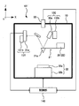
- FIG. 3 is a schematic configuration diagram showing a general scanning probe microscope.
- One direction horizontal to the ground is defined as an X direction
- a direction horizontal to the ground and perpendicular to the X direction is defined as a Y direction
- a direction perpendicular to the X direction and the Y direction is defined as a Z direction.
- the scanning probe microscope 101 includes a housing 10 and a control unit 140 that controls the entire scanning probe microscope 101.
- a sample mounting table (sample placement unit) 32 on which a sample is placed a cantilever support unit 20 to which the cantilever 21 can be attached and detached, a light source unit 130 that emits laser light, and reflected light are detected.
- a light detection unit 131 that performs the above-described operation.
- a CCD camera (imaging device) 33 is disposed on the top of the housing 10 (see, for example, Patent Document 1 and Patent Document 2).
- the sample mounting table 32 is installed in the lower part of the housing 10, for example, a circular mounting surface 32a having a diameter of 15 mm in plan view, and a piezo scanner (scanning means) installed in the lower part of the mounting surface 32a. 32b.
- the piezo scanner 32b is controlled by the control unit 140.
- the placement surface 32a can be moved in the X direction, the Y direction, and the Z direction with respect to the housing 10 by the piezo scanner 32b. Accordingly, the measurer places the sample on the placement surface 32a and moves the placement surface 32a in the X direction, the Y direction, and the Z direction with respect to the housing 10 using the piezo scanner 32b.
- the initial position of the sample surface can be adjusted before the sample measurement, and the measurement position on the sample surface can be scanned in the X, Y, and Z directions during the sample measurement.
- the cantilever 21 is, for example, a plate-like body having a length of 100 ⁇ m, a width of 30 ⁇ m, and a thickness of 0.8 ⁇ m, and a sharp probe 21 a that protrudes downward is formed on the lower surface of the tip portion.
- the upper surface (rear surface) of the tip of the cantilever 21 is an irradiation surface on which the laser light from the light source unit 130 is irradiated.
- the other end portion of the cantilever 21 is fixed to the lower end surface of the cantilever support portion 20 with a fixture (not shown).
- Arbitrary fixing means such as a screw or a spring mechanism can be used as the fixing tool. Therefore, the measurer can select and install one cantilever 21 from a plurality of types of cantilevers 21 according to the sample and the measurement purpose.
- the cantilever support part 20 is installed in the right part of the housing
- the measurer attaches the cantilever 21 to the predetermined position on the lower end surface of the support body 22 with the fixture, and uses the support lever to support the housing 10 in the X, Y, and Z directions.
- the position of the cantilever 21 can be adjusted by moving the main body 22.
- the light source unit 130 is installed in the upper right part of the housing 10 and includes a laser element 30a that emits laser light and a biaxial positioning stage 130b that moves the laser element 30a.
- the laser element 30a is movable in the X direction and the Y direction with respect to the housing 10 by the biaxial positioning stage 130b.
- the laser light emitted from the laser element 30a is emitted substantially toward the left (predetermined direction), is refracted at a right angle by a beam splitter (not shown), and is perpendicular to the emission direction. Irradiated in a circular shape with a diameter of 50 ⁇ m. Accordingly, the measurer can adjust the irradiation position (spot) irradiated with the laser light by moving the laser element 30a with respect to the housing 10 using the biaxial positioning stage 130b. ing.
- the light detection unit 131 is installed in the upper left part of the housing 10, and includes a quadrant photodetector 31a that detects reflected light reflected from the back surface of the cantilever 21, and two axes that move the quadrant photodetector 31a.
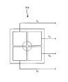
- FIG. 4 is a schematic configuration diagram showing a quadrant photodetector.
- Quadrant photodetector 31a is square for receiving the light beam (e.g., an area 4 mm 2) and the first photodiode having a first light receiving surface of the second rectangle for receiving the light beam (e.g., an area 4 mm 2)
- a fourth photodiode having a fourth light receiving surface.
- first to fourth light receiving surfaces are arranged adjacent to each other in 2 rows and 2 columns and perpendicular to the optical axis of the reflected light. And control the amount of light received in the vertical direction ((I 1 + I 3 )-(I 2 + I 4 )) and the amount of light received in the horizontal direction (((I 1 + I 2 )-(I 3 + I 4 )) Output to the unit 140.
- such a four-divided photodetector 31a can be moved in the X direction and the Y direction with respect to the housing 10 by the biaxial positioning stage 131b.
- the reflected light from the back surface of the cantilever 21 is reflected substantially upward to the left, and is irradiated in a circular shape having a diameter of 50 ⁇ m, for example, on a surface perpendicular to the reflection direction.
- the measurer can adjust the initial position of the reflected light on the light receiving surface before measuring the sample by moving the quadrant photodetector 31a with respect to the housing 10 using the biaxial positioning stage 131b. It can be done. Then, the amount of deflection (displacement) generated in the cantilever 21 by the sample surface during sample measurement is detected by the amount of movement of the reflected light from the initial position on the light receiving surface.
- the cantilever 21 can be freely attached to and detached from the support portion main body 22 as described above. Therefore, after replacing with another cantilever 21, the position of the laser element 30a is adjusted so that the laser light is irradiated on the irradiation surface of the cantilever 21, and further, the reflected light is irradiated on the center of the light receiving surface. It is necessary to adjust the position of the split photodetector 31a. At this time, since the position of the laser element 30a must be adjusted at a level of 0.1 mm or less, the scanning probe microscope 101 enlarges the vicinity of the tip of the cantilever 21 and the irradiation position (spot) of the laser beam. A CCD camera 33 for observation is provided.
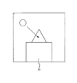
- FIG. 5 is a diagram illustrating an example of an observation image observed by the CCD camera 33.
- the measurer moves the laser element 30a in the X direction and the Y direction using the biaxial positioning stage 130b while observing the observation image of the CCD camera 33 so that the irradiation surface of the cantilever 21 is irradiated with the laser light.
- the irradiation position (spot) irradiated with the laser light is adjusted (light source control step).
- the measurer makes the reflected light irradiate the center of the light receiving surface of the quadrant photodetector 31a, that is, the amount of light received in the vertical direction ((I 1 + I 3 ) ⁇ (I 2 + I 4 )). ) And the amount of light received in the horizontal direction (((I 1 + I 2 ) ⁇ (I 3 + I 4 )) are 0, respectively, using the biaxial positioning stage 131b, the quadrant photodetector 31a is moved in the X direction. And the Y direction are adjusted to adjust the position where the reflected light is irradiated on the light receiving surface (detection unit control step).
- the measurer moves the laser element 30a in the X direction and the Y direction using the biaxial positioning stage 130b based on experience and intuition while observing the observation image.
- the quadrant photodetector 31a is moved in the X direction and the Y direction using the biaxial positioning stage 131b, there is a problem that much time and labor are required.
- the biaxial positioning stage 130b is manually operated when moving the laser element 30a in the X direction and the Y direction. Since it sways, it was difficult to discriminate movement due to adjustment of the laser element 30a and movement due to sway.
- the inventors examined an optical axis adjustment method for automatically adjusting the position of the laser element 30a and the position of the quadrant photodetector 31a.
- a drive mechanism is attached to the light source unit, the light source unit becomes heavier and the center of gravity becomes higher, so it was thought that the SPM image also shakes. The acquisition was found to have no effect. Therefore, an ultrasonic motor or a stepping motor, which is a lighter drive mechanism, is attached to the light source unit.
- the cantilever support can be mounted by selecting one cantilever from multiple types of cantilevers according to the sample and the purpose of measurement, as in the past.
- the control unit detects the position of the apex of the cantilever triangle and the irradiation position of the laser beam based on the acquired observation image, and lasers the laser at a predetermined distance from the apex position of the cantilever triangle to the end. It has been found that stage control using an ultrasonic motor or a stepping motor is performed so that the irradiation position of light comes.
- a scanning probe microscope includes a sample placement portion where a sample is placed, a light source portion that emits laser light in a predetermined direction, a cantilever placed above the sample surface, and a cantilever to which the cantilever is attached.
- the displacement of the cantilever due to the sample surface is calculated based on a support, a light detection unit having a light receiving surface irradiated with reflected light reflected by the irradiation surface of the cantilever, and a position of the reflected light on the light receiving surface.
- a scanning probe microscope including a control unit, wherein a stage for moving the light source unit in the XY direction, a tip end portion of the cantilever attached to the cantilever support unit, and an irradiation position of the laser beam are photographed;
- An imaging device for acquiring an observation image, and the cantilever support portion includes a plurality of types of cantilevers.
- One selected cantilever can be attached, and when the cantilever is attached to the cantilever support portion, the control unit can detect the position of the feature point of the cantilever based on the observation image. And the irradiation position of the said laser beam is detected, and the light source part control process which controls the said stage so that the said laser beam is irradiated to the said irradiation surface is performed.
- the “predetermined direction” is predetermined by a designer or the like, and is, for example, the left direction.
- the scanning probe microscope of the present invention it is possible to automatically adjust the laser light so that the irradiation surface of the cantilever is irradiated.
- the scanning probe microscope of the present invention further includes a stage for moving the light detection unit in the X and Y directions, and the control unit is configured to detect reflected light detected by the light detection unit after the light source unit control step. You may make it perform the detection part control process which controls the said stage so that the said reflected light is irradiated to the center of the said light-receiving surface based on a position. As described above, according to the scanning probe microscope of the present invention, it is possible to automatically adjust so that the reflected light is applied to the center of the light receiving surface.
- the characteristic point of the cantilever is the tip of the cantilever.
- the laser beam is placed at a predetermined distance from the tip of the cantilever to the end. You may make it control the said stage so that it may irradiate.
- the “predetermined distance” is predetermined by a designer or the like, and is, for example, 1 mm.
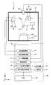
- the schematic block diagram which shows the scanning probe microscope of this invention.
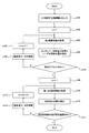
- the flowchart explaining the optical axis adjustment method The schematic block diagram which shows a general scanning probe microscope.
- the schematic block diagram which shows 4 division
- FIG. 1 is a schematic configuration diagram showing a scanning probe microscope of the present invention.
- the same reference numerals are assigned to the same components as those of the scanning probe microscope 101 described above.
- the scanning probe microscope 1 includes a housing 10 and a control unit 40 that controls the entire scanning probe microscope 1. Inside the housing 10, a sample mounting table (sample placement unit) 32 on which a sample is placed, a cantilever support unit 20 to which the cantilever 21 can be attached and detached, a light source unit 30 that emits laser light, and reflected light are detected. The light detection unit 31 is arranged.
- a CCD camera 33 is disposed on the top of the housing 10.
- the light source unit 30 is installed in the upper right part of the housing 10 and includes a laser element 30a that emits laser light and an ultrasonic motor 30b that moves the laser element 30a (laser element stage).
- the laser element 30a can be moved in the horizontal / vertical direction with respect to the housing 10 by the ultrasonic motor 30b.
- the irradiation position (spot) irradiated with laser light can be adjusted by moving the laser element 30a with respect to the housing
- the light detection unit 31 is installed in the upper left part of the housing 10 and detects the reflected light reflected by the back surface of the cantilever 21 and an ultrasonic wave that moves the four-part photodetector 31a. And a motor 31b.
- the quadrant photodetector 31a (four-segment photodetector stage) can be moved in the horizontal direction and the vertical direction with respect to the housing 10 by the ultrasonic motor 31b. Thereby, the initial position of the reflected light on the light receiving surface can be adjusted before the sample measurement by moving the quadrant photodetector 31a with respect to the housing 10 using the ultrasonic motor 31b. Yes.
- the control unit 40 includes a CPU 41, a memory 42, a display device 43, and an operation unit 44. Further, the function processed by the CPU 41 will be described as a block.
- the image reading unit 41a that acquires the nth observation image from the CCD camera 33, the position of the feature point of the cantilever 21 and the laser beam based on the acquired nth observation image.
- the m-th light intensity information is acquired from the laser beam difference calculation unit 41b that detects the irradiation position of the laser beam and calculates the positional relationship thereof, the laser axis drive unit 41c that controls the ultrasonic motor 30b, and the quadrant photodetector 31a. It has a detector reading unit 41d, a reflected light difference calculation unit 41e that detects the position of the reflected light based on the acquired m-th light intensity information, and a detector shaft drive unit 41f that controls the ultrasonic motor 31b.
- a predetermined offset ( ⁇ x, ⁇ y) for determining that the position of the laser beam matches is set and stored.
- the image reading unit 41a When receiving the input signal “optical axis adjustment” from the operation unit 44, the image reading unit 41a performs control to acquire the nth observation image from the CCD camera 33.
- the laser beam difference calculation unit 41b performs control to detect the position of the tip (feature point) of the cantilever 21 and the irradiation position of the laser beam based on the nth observation image and calculate the positional relationship. Specifically, the position of the tip (feature point) of the cantilever 21 is detected from the n-th observation image, and the distances x and y in the X / Y direction are calculated from the tip (feature point) of the cantilever 21. Then, it is determined whether or not the laser beam irradiation position exists within the predetermined offset ( ⁇ x, ⁇ y). When it is determined that the laser beam irradiation position does not exist, the distances x and y are set as the moving direction and moving amount of the laser element 30a. .
- the laser axis driving unit 41c is based on the moving direction and moving amount of the laser element 30a. To control.
- the detector reading unit 41d acquires the mth light intensity information from the quadrant photodetector 31a when the laser beam difference calculation unit 41b determines that the laser beam irradiation position is within a predetermined offset ( ⁇ x, ⁇ y). Control.
- the reflected light difference calculation unit 41e performs control to detect the position of the reflected light based on the mth light intensity information I 1m , I 2m , I 3m , and I 4m . Specifically, the position of the reflected light is detected from the m-th light intensity information I 1m , the m-th light intensity information I 2m , the m-th light intensity information I 3m, and the m-th light intensity information I 4m . And the received light amount in the vertical direction ((I 1m + I 3m )-(I 2m + I 4m )) and the received light amount in the horizontal direction (((I 1m + I 2m )-(I 3m + I 4m )) are zero. When it is determined that it is not within the predetermined range, the moving direction and the moving amount of the four-divided photodetector 31a necessary for matching the position of the reflected light and the center of the light receiving surface are calculated. .
- the detector shaft driving unit 41f determines the movement direction and the movement amount of the quadrant photodetector 31a. Based on this, the ultrasonic motor 31b is controlled.
- the measurer inputs an input signal “optical axis adjustment” using the operation unit 44.
- the image reading unit 41a acquires the nth observation image from the CCD camera 33.
- the laser light difference calculation unit 41b detects the position of the tip (feature point) of the cantilever 21 and the irradiation position of the laser light based on the nth observation image, and calculates the positional relationship. .
- the laser beam difference calculation unit 41b determines whether or not the irradiation position of the laser beam exists within a predetermined offset ( ⁇ x, ⁇ y).
- the laser axis driving unit 41c is based on the moving direction and moving amount of the laser element 30a in the process of step s106. Then, the ultrasonic motor 30b is controlled (light source control process).
- the detector reading unit 41d acquires m-th light intensity information from the four-split photodetector 31a.
- the reflected light difference calculating unit 41e detects the position of the reflected light based on the mth light intensity information I 1m , I 2m , I 3m , and I 4m .
- the detector shaft drive part 41f controls the ultrasonic motor 31b based on the moving direction and the moving amount of the 4-part photodetector 31a ( Detection unit control step).
- steps s109 to s111 is repeated until it is determined that it is within the predetermined range.
- this flowchart is terminated.
- the scanning probe microscope 1 of the present invention it is possible to automatically adjust the laser light so that the irradiation surface of the cantilever 21 is irradiated. Moreover, it can adjust automatically so that reflected light may be irradiated to the center of a light-receiving surface.
- the present invention can be used for a scanning probe microscope suitable for observing a sample surface.
Landscapes
- Physics & Mathematics (AREA)
- Health & Medical Sciences (AREA)
- General Health & Medical Sciences (AREA)
- General Physics & Mathematics (AREA)
- Nuclear Medicine, Radiotherapy & Molecular Imaging (AREA)
- Radiology & Medical Imaging (AREA)
- Length Measuring Devices With Unspecified Measuring Means (AREA)
- Length Measuring Devices By Optical Means (AREA)
Abstract
レーザ素子の位置と光検出器の位置とを自動的に調整することができる走査型プローブ顕微鏡を提供するために、該走査型プローブ顕微鏡1は、試料配置部32と、光源部30と、カンチレバー21とこれが取付けられるカンチレバー支持部21と、光検出部31と、制御部40とを備え、さらに光源部30をXY方向に移動させる超音波モータ又はステッピングモータ30bと、観察画像を取得するCCDカメラ33とを備え、カンチレバー支持部20には複数のカンチレバー21から選択された一つが取付けられるようになっており、制御部40は、カンチレバー支持部20にカンチレバー21が取付けられた際、観察画像に基づいてカンチレバー21の特徴点の位置及びレーザ光の照射位置を検出し、レーザ光が照射面に照射されるようにモータ30bを制御する光源部制御工程を実行する。
Description
本発明は、走査型プローブ顕微鏡に関し、特にカンチレバーの背面を照射面として利用する光学式変位検出系を備える走査型プローブ顕微鏡に関する。
走査型プローブ顕微鏡として、プローブ(カンチレバー)と試料(金属、半導体、生物、有機分子、絶縁物等の非導電物質等)の表面との間に働く原子間力を測定することによって、試料表面の形状(SPM画像)を観察することができる原子間力顕微鏡(AFM)が知られている。図3は、一般的な走査型プローブ顕微鏡を示す概略構成図である。なお、地面に水平な一方向をX方向とし、地面に水平でX方向と垂直な方向をY方向とし、X方向とY方向とに垂直な方向をZ方向とする。
走査型プローブ顕微鏡101は、筐体10と、走査型プローブ顕微鏡101全体を制御する制御部140とを備える。筐体10内部には、試料が載置される試料載置台(試料配置部)32と、カンチレバー21が着脱可能なカンチレバー支持部20と、レーザ光を出射する光源部130と、反射光を検出する光検出部131とが配置されている。また、筐体10上部にはCCDカメラ(撮像装置)33が配置されている(例えば、特許文献1及び特許文献2参照)。
試料載置台32は、筐体10の下部に設置されており、例えば平面視で直径15mmの円形状である載置面32aと、載置面32aの下部に設置されたピエゾスキャナ(走査手段)32bとを備える。ピエゾスキャナ32bは、制御部140によって制御される。そして、載置面32aは、ピエゾスキャナ32bによって筐体10に対してX方向とY方向とZ方向とに移動可能となっている。これにより、測定者は、載置面32aに試料を載置するとともに、ピエゾスキャナ32bを用いて筐体10に対してX方向とY方向とZ方向とに載置面32aを移動させることで、試料測定前に試料表面の初期位置を調整することができ、さらに試料測定中に試料表面の測定位置をX方向とY方向とZ方向とに走査することができるようになっている。
カンチレバー21は、例えば長さ100μm、幅30μm、厚さ0.8μmの板状体であり、先端部の下面に下方に向かって突出する先鋭な探針21aが形成されている。そして、カンチレバー21の先端部の上面(背面)が、光源部130からのレーザ光が照射されるための照射面となる。また、カンチレバー21の他端部は、カンチレバー支持部20の下端面に固定具(図示せず)で固定されるようになっている。固定具は、ネジやバネ機構等の任意の固定手段を用いることができる。よって、測定者は、試料や測定目的に応じて複数種類のカンチレバー21の内から一のカンチレバー21を選択して取付けて用いることができるようになっている。
カンチレバー支持部20は、筐体10の右部に設置されており、支持部本体22と支持レバー(図示せず)と固定具(図示せず)とを備える。そして、支持部本体22が支持レバーによって筐体10に対してX方向とY方向とZ方向とに移動可能となっている。これにより、測定者は、支持部本体22の下端面の所定位置にカンチレバー21を固定具で取付けるとともに、支持レバーを用いて筐体10に対してX方向とY方向とZ方向とに支持部本体22を移動させることで、カンチレバー21の位置を調整することができるようになっている。
光源部130は、筐体10の右上部に設置されており、レーザ光を出射するレーザ素子30aと、レーザ素子30aを移動させる2軸位置決めステージ130bとを備える。そして、レーザ素子30aが2軸位置決めステージ130bによって筐体10に対してX方向とY方向とに移動可能となっている。レーザ素子30aから出射されるレーザ光は、略左方(所定方向)に向かって出射されており、ビームスプリッタ(図示せず)にて直角に屈折し、その出射方向に垂直となる面では例えば直径50μmの円形状に照射される。これにより、測定者は、2軸位置決めステージ130bを用いて筐体10に対してレーザ素子30aを移動させることで、レーザ光が照射される照射位置(スポット)を調整することができるようになっている。
光検出部131は、筐体10の左上部に設置されており、カンチレバー21の背面で反射された反射光を検出する4分割光検出器31aと、4分割光検出器31aを移動させる2軸位置決めステージ131bとを備える。
図4は、4分割光検出器を示す概略構成図である。4分割光検出器31aは、光束を受光する四角形(例えば、面積4mm2)の第一の受光面を有する第一のフォトダイオードと、光束を受光する四角形(例えば、面積4mm2)の第二の受光面を有する第二のフォトダイオードと、光束を受光する四角形(例えば、面積4mm2)の第三の受光面を有する第三のフォトダイオードと、光束を受光する四角形(例えば、面積4mm2)の第四の受光面を有する第四のフォトダイオードとを有する。また、第一~第四の4つの受光面は、2行2列となるように隣接し、かつ、反射光の光軸と垂直となるように配置されている。そして、垂直方向の受光量((I1+I3)-(I2+I4))と水平方向の受光量(((I1+I2)-(I3+I4))を制御部140に出力する。
図4は、4分割光検出器を示す概略構成図である。4分割光検出器31aは、光束を受光する四角形(例えば、面積4mm2)の第一の受光面を有する第一のフォトダイオードと、光束を受光する四角形(例えば、面積4mm2)の第二の受光面を有する第二のフォトダイオードと、光束を受光する四角形(例えば、面積4mm2)の第三の受光面を有する第三のフォトダイオードと、光束を受光する四角形(例えば、面積4mm2)の第四の受光面を有する第四のフォトダイオードとを有する。また、第一~第四の4つの受光面は、2行2列となるように隣接し、かつ、反射光の光軸と垂直となるように配置されている。そして、垂直方向の受光量((I1+I3)-(I2+I4))と水平方向の受光量(((I1+I2)-(I3+I4))を制御部140に出力する。
また、このような4分割光検出器31aは、2軸位置決めステージ131bによって筐体10に対してX方向とY方向とに移動可能となっている。カンチレバー21の背面からの反射光は、略左上方に向かって反射されており、その反射方向に垂直となる面では例えば直径50μmの円形状に照射される。これにより、測定者は、2軸位置決めステージ131bを用いて筐体10に対して4分割光検出器31aを移動させることで、試料測定前に受光面における反射光の初期位置を調整することができるようになっている。そして、試料測定の際に試料表面によってカンチレバー21に生じたたわみ量(変位量)を、受光面における反射光の初期位置からの移動量で検出している。
ところで、このような走査型プローブ顕微鏡101では、上述したようにカンチレバー21は支持部本体22に対して取付け・取外し自在となっている。よって、別のカンチレバー21に交換した後は、レーザ光がカンチレバー21の照射面に照射されるようにレーザ素子30aの位置を調整し、さらに反射光が受光面の中心に照射されるように4分割光検出器31aの位置を調整することが必要である。このとき、0.1mm以下のレベルでレーザ素子30aの位置を調整しなければならないため、走査型プローブ顕微鏡101は、カンチレバー21の先端部付近とレーザ光の照射位置(スポット)とを拡大して観察するためのCCDカメラ33を備えている。
ここで、走査型プローブ顕微鏡101において、レーザ素子30aの位置と4分割光検出器31aの位置とを調整する光軸調整方法について説明する。図5は、CCDカメラ33で観察される観察画像の一例を示す図である。
まず、測定者は、レーザ光がカンチレバー21の照射面に照射されるように、CCDカメラ33の観察画像を観察しながら2軸位置決めステージ130bを用いてレーザ素子30aをX方向とY方向とに移動させることで、レーザ光が照射される照射位置(スポット)を調整する(光源部制御工程)。
次に、測定者は、反射光が4分割光検出器31aの受光面の中心に照射されるように、すなわち垂直方向の受光量((I1+I3)-(I2+I4))と水平方向の受光量(((I1+I2)-(I3+I4))がそれぞれ0となるように、2軸位置決めステージ131bを用いて4分割光検出器31aをX方向とY方向とに移動させることで、受光面における反射光が照射される位置を調整する(検出部制御工程)。
しかしながら、上述したような光軸調整方法では、測定者は、観察画像を観察しながら経験と勘とに基づいて2軸位置決めステージ130bを用いてレーザ素子30aをX方向とY方向とに移動させるとともに、2軸位置決めステージ131bを用いて4分割光検出器31aをX方向とY方向とに移動させることになるため、非常に多くの時間と労力とを要するという問題点があった。特に、経験の浅い測定者(初心者)にとっては、レーザ素子30aをX方向とY方向とに移動させるときには2軸位置決めステージ130bを手動で操作するため、光源部130等が揺れることにより観察画像も揺れるので、レーザ素子30aの調整による動きと揺れによる動きとを判別するのが困難であった。
本件発明者らは、レーザ素子30aの位置と4分割光検出器31aの位置とを自動的に調整する光軸調整方法について検討した。そして、従来は光源部に駆動機構を取付けると、光源部が重くなるとともに重心が高くなることから、SPM画像も揺れるものと考えられていたが、なるべく軽量化した駆動機構を用いれば、SPM画像取得には影響がないことがわかった。よって、光源部に軽量化した駆動機構である超音波モータやステッピングモータを取付けることにした。
また、カンチレバー支持部には、従来同様試料や測定目的に応じて複数種類のカンチレバーの内から一のカンチレバーを選択して取付けられるようになっているが、この複数種類のカンチレバーの先端部は全て三角形となっており、さらに照射面が三角形の頂点から末端に向かって所定距離の位置に形成されている。そこで、制御部は、取得した観察画像に基づいて、カンチレバーの三角形の頂点の位置とレーザ光の照射位置とを検出し、カンチレバーの三角形の頂点の位置から末端に向かって所定距離の位置にレーザ光の照射位置が来るように、超音波モータやステッピングモータを利用したステージ制御をすることを見出した。
また、カンチレバー支持部には、従来同様試料や測定目的に応じて複数種類のカンチレバーの内から一のカンチレバーを選択して取付けられるようになっているが、この複数種類のカンチレバーの先端部は全て三角形となっており、さらに照射面が三角形の頂点から末端に向かって所定距離の位置に形成されている。そこで、制御部は、取得した観察画像に基づいて、カンチレバーの三角形の頂点の位置とレーザ光の照射位置とを検出し、カンチレバーの三角形の頂点の位置から末端に向かって所定距離の位置にレーザ光の照射位置が来るように、超音波モータやステッピングモータを利用したステージ制御をすることを見出した。
すなわち、本発明の走査型プローブ顕微鏡は、試料が配置される試料配置部と、レーザ光を所定方向に出射する光源部と、前記試料表面上方に配置されるカンチレバーと、前記カンチレバーが取付けられるカンチレバー支持部と、前記カンチレバーの照射面で反射した反射光が照射される受光面を有する光検出部と、前記受光面における反射光の位置に基づいて、前記試料表面による前記カンチレバーの変位を算出する制御部とを備える走査型プローブ顕微鏡であって、前記光源部をXY方向に移動させるステージと、前記カンチレバー支持部に取付けられた前記カンチレバーの先端部及び前記レーザ光の照射位置を撮影することにより、観察画像を取得する撮像装置とを備え、前記カンチレバー支持部には複数種類のカンチレバーの内から選択された一のカンチレバーが取付けられることが可能となっており、前記制御部は、前記カンチレバー支持部に前記カンチレバーが取付けられた際に、前記観察画像に基づいて、前記カンチレバーの特徴点の位置及び前記レーザ光の照射位置を検出し、前記レーザ光が前記照射面に照射されるように前記ステージを制御する光源部制御工程を実行するようにしている。
ここで、「所定方向」とは、設計者等によって予め決められており、例えば左方向等となる。
以上のように、本発明の走査型プローブ顕微鏡によれば、レーザ光がカンチレバーの照射面に照射されるように自動的に調整することができる。
(その他の課題を解決するための手段および効果)
また、本発明の走査型プローブ顕微鏡は、前記光検出部をXY方向に移動させるステージを備え、前記制御部は、前記光源部制御工程の実行後、前記光検出部で検出された反射光の位置に基づいて、前記反射光が前記受光面の中心に照射されるように前記ステージを制御する検出部制御工程を実行するようにしてもよい。
以上のように、本発明の走査型プローブ顕微鏡によれば、反射光が受光面の中心に照射されるように自動的に調整することができる。
また、本発明の走査型プローブ顕微鏡は、前記光検出部をXY方向に移動させるステージを備え、前記制御部は、前記光源部制御工程の実行後、前記光検出部で検出された反射光の位置に基づいて、前記反射光が前記受光面の中心に照射されるように前記ステージを制御する検出部制御工程を実行するようにしてもよい。
以上のように、本発明の走査型プローブ顕微鏡によれば、反射光が受光面の中心に照射されるように自動的に調整することができる。
そして、本発明の走査型プローブ顕微鏡は、前記カンチレバーの特徴点は、前記カンチレバーの先端であり、前記光源部制御工程で、前記カンチレバーの先端から末端に向かって所定距離の位置に前記レーザ光が照射されるように前記ステージを制御するようにしてもよい。
ここで、「所定距離」とは、設計者等によって予め決められており、例えば1mm等となる。
ここで、「所定距離」とは、設計者等によって予め決められており、例えば1mm等となる。
以下、本発明の実施形態について図面を用いて説明する。なお、本発明は、以下に説明するような実施形態に限定されるものではなく、本発明の趣旨を逸脱しない範囲で種々の態様が含まれることはいうまでもない。
図1は、本発明の走査型プローブ顕微鏡を示す概略構成図である。なお、先に述べた走査型プローブ顕微鏡101と同様のものについては、同じ符号を付している。
走査型プローブ顕微鏡1は、筐体10と、走査型プローブ顕微鏡1全体を制御する制御部40とを備える。筐体10内部には、試料が載置される試料載置台(試料配置部)32と、カンチレバー21が着脱可能なカンチレバー支持部20と、レーザ光を出射する光源部30と、反射光を検出する光検出部31とが配置されている。また、筐体10上部にはCCDカメラ33が配置されている。
走査型プローブ顕微鏡1は、筐体10と、走査型プローブ顕微鏡1全体を制御する制御部40とを備える。筐体10内部には、試料が載置される試料載置台(試料配置部)32と、カンチレバー21が着脱可能なカンチレバー支持部20と、レーザ光を出射する光源部30と、反射光を検出する光検出部31とが配置されている。また、筐体10上部にはCCDカメラ33が配置されている。
光源部30は、筐体10の右上部に設置されており、レーザ光を出射するレーザ素子30aと、レーザ素子30a(レーザ素子ステージ)を移動させる超音波モータ30bとを備える。そして、レーザ素子30aが超音波モータ30bによって筐体10に対して水平/垂直方向に移動可能となっている。これにより、超音波モータ30bを用いて筐体10に対してレーザ素子30aを移動させることで、レーザ光が照射される照射位置(スポット)を調整することができるようになっている。
光検出部31は、筐体10の左上部に設置されており、カンチレバー21の背面で反射された反射光を検出する4分割光検出器31aと、4分割光検出器31aを移動させる超音波モータ31bとを備える。そして、4分割光検出器31a(4分割光検出器ステージ)は、超音波モータ31bによって筐体10に対して水平方向と垂直方向とに移動可能となっている。これにより、超音波モータ31bを用いて筐体10に対して4分割光検出器31aを移動させることで、試料測定前に受光面における反射光の初期位置を調整することができるようになっている。
制御部40は、CPU41とメモリ42と表示装置43と操作部44とを備える。
また、CPU41が処理する機能をブロック化して説明すると、CCDカメラ33から第n観察画像を取得する画像読取部41aと、取得した第n観察画像に基づいてカンチレバー21の特徴点の位置及びレーザ光の照射位置を検出してその位置関係を計算するレーザ光差分計算部41bと、超音波モータ30bを制御するレーザ軸駆動部41cと、4分割光検出器31aから第m光強度情報を取得する検出器読取部41dと、取得した第m光強度情報に基づいて反射光の位置を検出する反射光差分計算部41eと、超音波モータ31bを制御する検出器軸駆動部41fとを有する。
また、CPU41が処理する機能をブロック化して説明すると、CCDカメラ33から第n観察画像を取得する画像読取部41aと、取得した第n観察画像に基づいてカンチレバー21の特徴点の位置及びレーザ光の照射位置を検出してその位置関係を計算するレーザ光差分計算部41bと、超音波モータ30bを制御するレーザ軸駆動部41cと、4分割光検出器31aから第m光強度情報を取得する検出器読取部41dと、取得した第m光強度情報に基づいて反射光の位置を検出する反射光差分計算部41eと、超音波モータ31bを制御する検出器軸駆動部41fとを有する。
また、メモリ42には、レーザ光の位置が合致したと判定するための所定オフセット(Δx, Δy)が設定され記憶されている。
画像読取部41aは、操作部44からの入力信号「光軸調整」を受信したときには、CCDカメラ33から第n観察画像を取得する制御を行う。
レーザ光差分計算部41bは、第n観察画像に基づいてカンチレバー21の先端(特徴点)の位置及びレーザ光の照射位置を検出してその位置関係を計算する制御を行う。具体的には、第n観察画像からカンチレバー21の先端(特徴点)の位置を検出し、カンチレバー21の先端(特徴点)からX/Y方向の距離x、yを算出する。そして、所定オフセット(Δx, Δy)内に、レーザ光の照射位置が存在するか否かを判定し、存在しないと判定したときには、距離x、yをレーザ素子30aの移動方向と移動量とする。
レーザ軸駆動部41cは、レーザ光差分計算部41bでレーザ素子30aの移動方向と移動量とが算出された際には、レーザ素子30aの移動方向と移動量とに基づいて、超音波モータ30bを制御する。
以上のような制御(段落0030から段落0032まで)を、レーザ中心位置とカンチレバー21の先端の距離の差分が所定オフセット(Δx, Δy)内に治まるまで繰り返す。
検出器読取部41dは、レーザ光差分計算部41bでレーザ光の照射位置が所定オフセット(Δx, Δy)内に存在すると判定されたときには、4分割光検出器31aから第m光強度情報を取得する制御を行う。
反射光差分計算部41eは、第m光強度情報I1m、I2m、I3m、I4mに基づいて反射光の位置を検出する制御を行う。
具体的には、第m光強度情報I1mと第m光強度情報I2mと第m光強度情報I3mと第m光強度情報I4mとから反射光の位置を検出する。そして、垂直方向の受光量((I1m+I3m)-(I2m+I4m))と水平方向の受光量(((I1m+I2m)-(I3m+I4m))がゼロになるか否かを判定し、所定範囲でないと判定したときには、反射光の位置と受光面の中心とを合わせるために必要となる4分割光検出器31aの移動方向と移動量とを算出する。
具体的には、第m光強度情報I1mと第m光強度情報I2mと第m光強度情報I3mと第m光強度情報I4mとから反射光の位置を検出する。そして、垂直方向の受光量((I1m+I3m)-(I2m+I4m))と水平方向の受光量(((I1m+I2m)-(I3m+I4m))がゼロになるか否かを判定し、所定範囲でないと判定したときには、反射光の位置と受光面の中心とを合わせるために必要となる4分割光検出器31aの移動方向と移動量とを算出する。
検出器軸駆動部41fは、反射光差分計算部41eで4分割光検出器31aの移動方向と移動量とが算出された際には、4分割光検出器31aの移動方向と移動量とに基づいて、超音波モータ31bを制御する。
ここで、走査型プローブ顕微鏡1において、レーザ素子30aの位置と4分割光検出器31aの位置とを調整する光軸調整方法について図2のフローチャートを用いて説明する。
まず、ステップs101の処理において、測定者は、操作部44を用いて入力信号「光軸調整」を入力する。
次に、ステップs102の処理において、レーザ素子30aの位置調整パラメータn=1とする。
次に、ステップs103の処理において、画像読取部41aは、CCDカメラ33から第n観察画像を取得する。
次に、ステップs104の処理において、レーザ光差分計算部41bは、第n観察画像に基づいてカンチレバー21の先端(特徴点)の位置及びレーザ光の照射位置を検出してその位置関係を計算する。
次に、ステップs103の処理において、画像読取部41aは、CCDカメラ33から第n観察画像を取得する。
次に、ステップs104の処理において、レーザ光差分計算部41bは、第n観察画像に基づいてカンチレバー21の先端(特徴点)の位置及びレーザ光の照射位置を検出してその位置関係を計算する。
次に、ステップs105の処理において、レーザ光差分計算部41bは、所定オフセット(Δx, Δy)内に、レーザ光の照射位置が存在するか否かを判定する。
そして、所定オフセット(Δx, Δy)内に、レーザ光の照射位置が存在しないと判定したときには、ステップs106の処理において、レーザ軸駆動部41cは、レーザ素子30aの移動方向と移動量とに基づいて、超音波モータ30bを制御する(光源部制御工程)。
そして、所定オフセット(Δx, Δy)内に、レーザ光の照射位置が存在しないと判定したときには、ステップs106の処理において、レーザ軸駆動部41cは、レーザ素子30aの移動方向と移動量とに基づいて、超音波モータ30bを制御する(光源部制御工程)。
続いて、ステップs107の処理において、n=n+1とした後、ステップs103の処理に戻る。つまり、所定オフセット(Δx, Δy)内に、レーザ光の照射位置が存在すると判定するまで、ステップs103~s105の処理は繰り返される。
一方、所定オフセット(Δx, Δy)内に、レーザ光の照射位置が存在すると判定したときには、ステップs108の処理において、4分割光検出器31aの位置調整パラメータm=1とする。
一方、所定オフセット(Δx, Δy)内に、レーザ光の照射位置が存在すると判定したときには、ステップs108の処理において、4分割光検出器31aの位置調整パラメータm=1とする。
次に、ステップs109の処理において、検出器読取部41dは、4分割光検出器31aから第m光強度情報を取得する。
次に、ステップs110の処理において、反射光差分計算部41eは、第m光強度情報I1m、I2m、I3m、I4mに基づいて反射光の位置を検出する。
次に、ステップs110の処理において、反射光差分計算部41eは、第m光強度情報I1m、I2m、I3m、I4mに基づいて反射光の位置を検出する。
次に、ステップs111の処理において、垂直方向の受光量((I1m+I3m)-(I2m+I4m))と水平方向の受光量(((I1m+I2m)-(I3m+I4m))がゼロであるか否かを判定する。
そして、所定範囲内でないと判定したときには、ステップs112の処理において、検出器軸駆動部41fは、4分割光検出器31aの移動方向と移動量とに基づいて、超音波モータ31bを制御する(検出部制御工程)。
そして、所定範囲内でないと判定したときには、ステップs112の処理において、検出器軸駆動部41fは、4分割光検出器31aの移動方向と移動量とに基づいて、超音波モータ31bを制御する(検出部制御工程)。
続いて、ステップs113の処理において、m=m+1とした後、ステップs109の処理に戻る。つまり、所定範囲内であると判定するまで、ステップs109~s111の処理は繰り返される。
一方、所定範囲内であると判定したときには、本フローチャートを終了させる。
一方、所定範囲内であると判定したときには、本フローチャートを終了させる。
以上のように、本発明の走査型プローブ顕微鏡1によれば、レーザ光がカンチレバー21の照射面に照射されるように自動的に調整することができる。また、反射光が受光面の中心に照射されるように自動的に調整することができる。
<他の実施形態>
上述した走査型プローブ顕微鏡1では、超音波モータ30b、31bを備える構成を示したが、これに代えてステッピングモータ、もしくはその他の駆動系を備えるような構成としてもよい。
上述した走査型プローブ顕微鏡1では、超音波モータ30b、31bを備える構成を示したが、これに代えてステッピングモータ、もしくはその他の駆動系を備えるような構成としてもよい。
本発明は、試料表面の観察に適した走査型プローブ顕微鏡等に使用することができる。
1 走査型プローブ顕微鏡
20 カンチレバー支持部
21 カンチレバー
30 光源部
30b 超音波モータ
31 光検出部
32 試料載置台(試料配置部)
32a 載置面
33 CCDカメラ
40 制御部
20 カンチレバー支持部
21 カンチレバー
30 光源部
30b 超音波モータ
31 光検出部
32 試料載置台(試料配置部)
32a 載置面
33 CCDカメラ
40 制御部
Claims (3)
- 試料が配置される試料配置部と、
レーザ光を所定方向に出射する光源部と、
前記試料表面上方に配置されるカンチレバーと、
前記カンチレバーが取付けられるカンチレバー支持部と、
前記カンチレバーの照射面で反射した反射光が照射される受光面を有する光検出部と、
前記受光面における反射光の位置に基づいて、前記試料表面による前記カンチレバーの変位を算出する制御部とを備える走査型プローブ顕微鏡であって、
前記光源部をXY方向に移動させるステージと、
前記カンチレバー支持部に取付けられた前記カンチレバーの先端部及び前記レーザ光の照射位置を撮影することにより、観察画像を取得する撮像装置とを備え、
前記カンチレバー支持部には複数種類のカンチレバーの内から選択された一のカンチレバーが取付けられることが可能となっており、
前記制御部は、前記カンチレバー支持部に前記カンチレバーが取付けられた際に、前記観察画像に基づいて、前記カンチレバーの特徴点の位置及び前記レーザ光の照射位置を検出し、前記レーザ光が前記照射面に照射されるように前記ステージを制御する光源部制御工程を実行することを特徴とする走査型プローブ顕微鏡。 - 前記光検出部をXY方向に移動させるステージを備え、
前記制御部は、前記光源部制御工程の実行後、前記光検出部で検出された反射光の位置に基づいて、前記反射光が前記受光面の中心に照射されるように前記ステージを制御する検出部制御工程を実行することを特徴とする請求項1に記載の走査型プローブ顕微鏡。 - 前記カンチレバーの特徴点は、前記カンチレバーの先端であり、
前記光源部制御工程で、前記カンチレバーの先端から末端に向かって所定距離の位置に前記レーザ光が照射されるように前記ステージを制御することを特徴とする請求項1又は請求項2に記載の走査型プローブ顕微鏡。
Priority Applications (1)
| Application Number | Priority Date | Filing Date | Title |
|---|---|---|---|
| PCT/JP2015/065068 WO2016189651A1 (ja) | 2015-05-26 | 2015-05-26 | 走査型プローブ顕微鏡 |
Applications Claiming Priority (1)
| Application Number | Priority Date | Filing Date | Title |
|---|---|---|---|
| PCT/JP2015/065068 WO2016189651A1 (ja) | 2015-05-26 | 2015-05-26 | 走査型プローブ顕微鏡 |
Publications (1)
| Publication Number | Publication Date |
|---|---|
| WO2016189651A1 true WO2016189651A1 (ja) | 2016-12-01 |
Family
ID=57393017
Family Applications (1)
| Application Number | Title | Priority Date | Filing Date |
|---|---|---|---|
| PCT/JP2015/065068 Ceased WO2016189651A1 (ja) | 2015-05-26 | 2015-05-26 | 走査型プローブ顕微鏡 |
Country Status (1)
| Country | Link |
|---|---|
| WO (1) | WO2016189651A1 (ja) |
Cited By (2)
| Publication number | Priority date | Publication date | Assignee | Title |
|---|---|---|---|---|
| WO2018155563A1 (ja) * | 2017-02-22 | 2018-08-30 | 株式会社島津製作所 | 走査型プローブ顕微鏡 |
| JP2021135134A (ja) * | 2020-02-26 | 2021-09-13 | 株式会社島津製作所 | 走査型プローブ顕微鏡および走査型プローブ顕微鏡における光軸調整方法 |
Citations (2)
| Publication number | Priority date | Publication date | Assignee | Title |
|---|---|---|---|---|
| JP2003014611A (ja) * | 2001-06-29 | 2003-01-15 | Olympus Optical Co Ltd | 走査型プローブ顕微鏡 |
| JP2005535878A (ja) * | 2002-08-09 | 2005-11-24 | カリフォルニア インスティテュート オブ テクノロジー | 走査型無開口蛍光顕微鏡のための改良された方法およびシステム |
-
2015
- 2015-05-26 WO PCT/JP2015/065068 patent/WO2016189651A1/ja not_active Ceased
Patent Citations (2)
| Publication number | Priority date | Publication date | Assignee | Title |
|---|---|---|---|---|
| JP2003014611A (ja) * | 2001-06-29 | 2003-01-15 | Olympus Optical Co Ltd | 走査型プローブ顕微鏡 |
| JP2005535878A (ja) * | 2002-08-09 | 2005-11-24 | カリフォルニア インスティテュート オブ テクノロジー | 走査型無開口蛍光顕微鏡のための改良された方法およびシステム |
Cited By (4)
| Publication number | Priority date | Publication date | Assignee | Title |
|---|---|---|---|---|
| WO2018155563A1 (ja) * | 2017-02-22 | 2018-08-30 | 株式会社島津製作所 | 走査型プローブ顕微鏡 |
| JP2018136224A (ja) * | 2017-02-22 | 2018-08-30 | 株式会社島津製作所 | 走査型プローブ顕微鏡 |
| JP2021135134A (ja) * | 2020-02-26 | 2021-09-13 | 株式会社島津製作所 | 走査型プローブ顕微鏡および走査型プローブ顕微鏡における光軸調整方法 |
| JP7255521B2 (ja) | 2020-02-26 | 2023-04-11 | 株式会社島津製作所 | 走査型プローブ顕微鏡および走査型プローブ顕微鏡における光軸調整方法 |
Similar Documents
| Publication | Publication Date | Title |
|---|---|---|
| US8791414B2 (en) | Dynamic focus adjustment with optical height detection apparatus in electron beam system | |
| JP5923026B2 (ja) | 画像取得装置及び画像取得方法 | |
| US10340170B2 (en) | Method and device for grooving wafers | |
| JP4452815B2 (ja) | 深さ測定装置 | |
| TWI772348B (zh) | 預測性聚焦追蹤裝置和方法 | |
| JP6588278B2 (ja) | 走査プローブ顕微鏡および走査プローブ顕微鏡の光軸調整方法 | |
| CN106814546B (zh) | 焦面检测装置、焦面标定方法与硅片曝光方法 | |
| KR20090018711A (ko) | 무한 보정 현미경의 자동 포커싱을 위한 방법 및 장치 | |
| JP2015028637A (ja) | 試料の空間位置の動的決定および動的再配置の装置および方法 | |
| JP2007517408A5 (ja) | ||
| JP5924191B2 (ja) | 走査型プローブ顕微鏡 | |
| CN107329246A (zh) | 一种扫描粒子束显微镜系统及聚焦控制方法 | |
| JP6309366B2 (ja) | 荷電粒子線装置における高さ測定装置およびオートフォーカス装置 | |
| WO2016189651A1 (ja) | 走査型プローブ顕微鏡 | |
| CN114778514B (zh) | 基于拉曼分析的无损高深宽比结构的测量装置及方法 | |
| TWI911808B (zh) | 粒子顯微鏡系統及確定其中樣本排列的方法 | |
| CN207020390U (zh) | 一种扫描粒子束显微镜系统 | |
| WO2010067570A1 (ja) | 走査型プローブ顕微鏡の出力処理方法および走査型プローブ顕微鏡 | |
| JP2003014611A (ja) | 走査型プローブ顕微鏡 | |
| JP2015170539A (ja) | 欠陥観察装置及びその方法 | |
| JP6101603B2 (ja) | ステージ装置および荷電粒子線装置 | |
| WO2022145391A1 (ja) | 走査型共焦点顕微鏡および走査型共焦点顕微鏡の調整方法 | |
| KR102896531B1 (ko) | 하전 입자선 장치 및 하전 입자선 장치의 제어 방법 | |
| US20240329381A1 (en) | System and method for microscope optical alignment | |
| JPH0982264A (ja) | パターン検査装置および走査型電子顕微鏡 |
Legal Events
| Date | Code | Title | Description |
|---|---|---|---|
| 121 | Ep: the epo has been informed by wipo that ep was designated in this application |
Ref document number: 15893286 Country of ref document: EP Kind code of ref document: A1 |
|
| NENP | Non-entry into the national phase |
Ref country code: DE |
|
| NENP | Non-entry into the national phase |
Ref country code: JP |
|
| 122 | Ep: pct application non-entry in european phase |
Ref document number: 15893286 Country of ref document: EP Kind code of ref document: A1 |