WO2016188443A1 - 电源线组件和电子设备 - Google Patents
电源线组件和电子设备 Download PDFInfo
- Publication number
- WO2016188443A1 WO2016188443A1 PCT/CN2016/083414 CN2016083414W WO2016188443A1 WO 2016188443 A1 WO2016188443 A1 WO 2016188443A1 CN 2016083414 W CN2016083414 W CN 2016083414W WO 2016188443 A1 WO2016188443 A1 WO 2016188443A1
- Authority
- WO
- WIPO (PCT)
- Prior art keywords
- power
- assembly
- power transmission
- electronic device
- contact
- Prior art date
Links
Images


Classifications
-
- H—ELECTRICITY
- H01—ELECTRIC ELEMENTS
- H01R—ELECTRICALLY-CONDUCTIVE CONNECTIONS; STRUCTURAL ASSOCIATIONS OF A PLURALITY OF MUTUALLY-INSULATED ELECTRICAL CONNECTING ELEMENTS; COUPLING DEVICES; CURRENT COLLECTORS
- H01R13/00—Details of coupling devices of the kinds covered by groups H01R12/70 or H01R24/00 - H01R33/00
- H01R13/02—Contact members
-
- H—ELECTRICITY
- H01—ELECTRIC ELEMENTS
- H01R—ELECTRICALLY-CONDUCTIVE CONNECTIONS; STRUCTURAL ASSOCIATIONS OF A PLURALITY OF MUTUALLY-INSULATED ELECTRICAL CONNECTING ELEMENTS; COUPLING DEVICES; CURRENT COLLECTORS
- H01R24/00—Two-part coupling devices, or either of their cooperating parts, characterised by their overall structure
- H01R24/66—Two-part coupling devices, or either of their cooperating parts, characterised by their overall structure with pins, blades or analogous contacts and secured to apparatus or structure, e.g. to a wall
- H01R24/68—Two-part coupling devices, or either of their cooperating parts, characterised by their overall structure with pins, blades or analogous contacts and secured to apparatus or structure, e.g. to a wall mounted on directly pluggable apparatus
-
- F—MECHANICAL ENGINEERING; LIGHTING; HEATING; WEAPONS; BLASTING
- F04—POSITIVE - DISPLACEMENT MACHINES FOR LIQUIDS; PUMPS FOR LIQUIDS OR ELASTIC FLUIDS
- F04D—NON-POSITIVE-DISPLACEMENT PUMPS
- F04D19/00—Axial-flow pumps
- F04D19/002—Axial flow fans
-
- F—MECHANICAL ENGINEERING; LIGHTING; HEATING; WEAPONS; BLASTING
- F04—POSITIVE - DISPLACEMENT MACHINES FOR LIQUIDS; PUMPS FOR LIQUIDS OR ELASTIC FLUIDS
- F04D—NON-POSITIVE-DISPLACEMENT PUMPS
- F04D25/00—Pumping installations or systems
- F04D25/02—Units comprising pumps and their driving means
- F04D25/06—Units comprising pumps and their driving means the pump being electrically driven
- F04D25/0673—Battery powered
-
- F—MECHANICAL ENGINEERING; LIGHTING; HEATING; WEAPONS; BLASTING
- F04—POSITIVE - DISPLACEMENT MACHINES FOR LIQUIDS; PUMPS FOR LIQUIDS OR ELASTIC FLUIDS
- F04D—NON-POSITIVE-DISPLACEMENT PUMPS
- F04D25/00—Pumping installations or systems
- F04D25/02—Units comprising pumps and their driving means
- F04D25/06—Units comprising pumps and their driving means the pump being electrically driven
- F04D25/0693—Details or arrangements of the wiring
-
- F—MECHANICAL ENGINEERING; LIGHTING; HEATING; WEAPONS; BLASTING
- F04—POSITIVE - DISPLACEMENT MACHINES FOR LIQUIDS; PUMPS FOR LIQUIDS OR ELASTIC FLUIDS
- F04D—NON-POSITIVE-DISPLACEMENT PUMPS
- F04D25/00—Pumping installations or systems
- F04D25/02—Units comprising pumps and their driving means
- F04D25/08—Units comprising pumps and their driving means the working fluid being air, e.g. for ventilation
-
- F—MECHANICAL ENGINEERING; LIGHTING; HEATING; WEAPONS; BLASTING
- F04—POSITIVE - DISPLACEMENT MACHINES FOR LIQUIDS; PUMPS FOR LIQUIDS OR ELASTIC FLUIDS
- F04D—NON-POSITIVE-DISPLACEMENT PUMPS
- F04D29/00—Details, component parts, or accessories
- F04D29/60—Mounting; Assembling; Disassembling
- F04D29/601—Mounting; Assembling; Disassembling specially adapted for elastic fluid pumps
-
- H—ELECTRICITY
- H01—ELECTRIC ELEMENTS
- H01R—ELECTRICALLY-CONDUCTIVE CONNECTIONS; STRUCTURAL ASSOCIATIONS OF A PLURALITY OF MUTUALLY-INSULATED ELECTRICAL CONNECTING ELEMENTS; COUPLING DEVICES; CURRENT COLLECTORS
- H01R13/00—Details of coupling devices of the kinds covered by groups H01R12/70 or H01R24/00 - H01R33/00
- H01R13/62—Means for facilitating engagement or disengagement of coupling parts or for holding them in engagement
- H01R13/6205—Two-part coupling devices held in engagement by a magnet
-
- H—ELECTRICITY
- H01—ELECTRIC ELEMENTS
- H01R—ELECTRICALLY-CONDUCTIVE CONNECTIONS; STRUCTURAL ASSOCIATIONS OF A PLURALITY OF MUTUALLY-INSULATED ELECTRICAL CONNECTING ELEMENTS; COUPLING DEVICES; CURRENT COLLECTORS
- H01R13/00—Details of coupling devices of the kinds covered by groups H01R12/70 or H01R24/00 - H01R33/00
- H01R13/62—Means for facilitating engagement or disengagement of coupling parts or for holding them in engagement
- H01R13/627—Snap or like fastening
-
- H—ELECTRICITY
- H01—ELECTRIC ELEMENTS
- H01R—ELECTRICALLY-CONDUCTIVE CONNECTIONS; STRUCTURAL ASSOCIATIONS OF A PLURALITY OF MUTUALLY-INSULATED ELECTRICAL CONNECTING ELEMENTS; COUPLING DEVICES; CURRENT COLLECTORS
- H01R13/00—Details of coupling devices of the kinds covered by groups H01R12/70 or H01R24/00 - H01R33/00
- H01R13/62—Means for facilitating engagement or disengagement of coupling parts or for holding them in engagement
- H01R13/629—Additional means for facilitating engagement or disengagement of coupling parts, e.g. aligning or guiding means, levers, gas pressure electrical locking indicators, manufacturing tolerances
-
- H—ELECTRICITY
- H01—ELECTRIC ELEMENTS
- H01R—ELECTRICALLY-CONDUCTIVE CONNECTIONS; STRUCTURAL ASSOCIATIONS OF A PLURALITY OF MUTUALLY-INSULATED ELECTRICAL CONNECTING ELEMENTS; COUPLING DEVICES; CURRENT COLLECTORS
- H01R31/00—Coupling parts supported only by co-operation with counterpart
- H01R31/06—Intermediate parts for linking two coupling parts, e.g. adapter
-
- H—ELECTRICITY
- H01—ELECTRIC ELEMENTS
- H01R—ELECTRICALLY-CONDUCTIVE CONNECTIONS; STRUCTURAL ASSOCIATIONS OF A PLURALITY OF MUTUALLY-INSULATED ELECTRICAL CONNECTING ELEMENTS; COUPLING DEVICES; CURRENT COLLECTORS
- H01R13/00—Details of coupling devices of the kinds covered by groups H01R12/70 or H01R24/00 - H01R33/00
- H01R13/02—Contact members
- H01R13/22—Contacts for co-operating by abutting
-
- H—ELECTRICITY
- H01—ELECTRIC ELEMENTS
- H01R—ELECTRICALLY-CONDUCTIVE CONNECTIONS; STRUCTURAL ASSOCIATIONS OF A PLURALITY OF MUTUALLY-INSULATED ELECTRICAL CONNECTING ELEMENTS; COUPLING DEVICES; CURRENT COLLECTORS
- H01R2103/00—Two poles
-
- H—ELECTRICITY
- H01—ELECTRIC ELEMENTS
- H01R—ELECTRICALLY-CONDUCTIVE CONNECTIONS; STRUCTURAL ASSOCIATIONS OF A PLURALITY OF MUTUALLY-INSULATED ELECTRICAL CONNECTING ELEMENTS; COUPLING DEVICES; CURRENT COLLECTORS
- H01R24/00—Two-part coupling devices, or either of their cooperating parts, characterised by their overall structure
- H01R24/38—Two-part coupling devices, or either of their cooperating parts, characterised by their overall structure having concentrically or coaxially arranged contacts
Definitions
- the present disclosure relates to the field of electronic device technologies, and in particular, to a power cord assembly and an electronic device.
- Electronic devices are gradually being applied to every corner of people's daily lives. For example, if the fan is driven by the motor to drive the fan blade to rotate, it can drive the air to circulate, which will bring coolness to the user. It is an essential home appliance for everyday home. Electronic devices usually come with a power cord and can be powered by plugging the cord into a mains outlet in the home.
- the present disclosure provides power cord assemblies and electronic devices to address deficiencies in the related art.
- a power cord assembly including:
- a power cord plug disposed at one end of the power cord and matched with the power socket
- a power cable base is disposed at the other end of the power cable, and the power supply contacts are respectively disposed on the top and bottom end faces of the power cable base.
- a top or bottom power contact contacts the power contact in the power transmission assembly to power the electronic device.
- any one of the top end or the bottom end of the power cord base is provided with a connection structure that cooperates with the power transmission component, and the connection structure can cooperate with the connection cooperation structure in the power transmission component, so that The power cord base and the power transmission component are fixed to each other.
- the connecting structure is a magnetic structure disposed on any one of the end faces, and when the one end face is matched with the power transmitting component, the magnetic structure and the connecting mating structure adopt magnetic adsorption The way to fix it.
- the connecting structure and the connecting mating structure are fixed by using a ⁇ fit.
- the vertical direction of the power supply contact is projected as a fan-shaped ring of a preset length, and a center corresponding to the fan ring is a center of an end surface of the power supply contact.
- an electronic device which is compatible with the power cord assembly of any of the above embodiments; the electronic device includes:
- a power transmission assembly including a power transmission contact, wherein the power transmission contact and the top or bottom end surface of the power line base are matched when the power transmission assembly and the power line base in the power line assembly are matched a power supply contact for contacting the power line assembly to the power transmission component;
- the power transmission component is further provided with a connection mating structure, and the connection mating structure can cooperate with a connection structure on any one of the top or bottom of the power cord base to make the power transmission component and the The power cord bases are fixed to each other.
- connection mating structure and the connecting structure are connected by magnetic adsorption.
- connection mating structure and the connecting structure are connected by using a ⁇ fit.
- the vertical direction of the power transmission contact is projected as a fan-shaped ring of a preset length, and a center corresponding to the fan ring is a center of a mating end surface corresponding to the base of the power line.
- the bottom of the electronic device is recessed inward to form an accommodating space that cooperates with the base of the power cable, and the power transmission component is disposed at a top end surface of the accommodating space.
- the electronic device is an electric fan.
- an electronic device which is compatible with the power cord assembly of any of the above embodiments; the electronic device includes:
- the power transmission assembly includes a power transmission contact and a connection mating structure, and the power transmission assembly is engageable with a power line base in the power line assembly;
- connection mating structure when the electronic device is configured in an adsorption mode, cooperates with a connection structure on any one of the top or bottom of the power cord base, so that the power transmission component and the power source
- the wire bases are fixed to each other, and the power transmission contacts are in contact with the power supply contacts on the one of the end faces to supply the power wire assembly to the power transmission component;
- the power transmission component When the electronic device is configured in a contact mode, the power transmission component is in contact with another end surface of the power cable base, so that the power transmission component and the power cable base are non-fixedly engaged, and the power contact The point is brought into contact with the power supply contacts on either of the end faces to power the power line assembly to the power transmission assembly.
- the present disclosure can conveniently implement the electronic device by arranging the power supply contacts on both sides of the power cable base in the power cord assembly, so that the electronic device is matched with the end surface of the power cable base without the connection structure.
- the combination and separation of the power cord base, and the electronic device is matched with the end surface of the power cord base provided with the connection structure, the electronic device can be closely connected with the power cable base to avoid accidental separation and power failure of the electronic device.
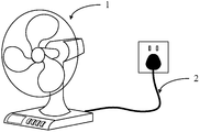
- Fig. 1 is a schematic structural view of an electric fan in the related art.
- FIG. 2 is a schematic structural diagram of a power cord assembly according to an exemplary embodiment of the present disclosure.
- FIG. 3 is a schematic structural view of a bottom portion of an electric fan structure according to an exemplary embodiment of the present disclosure.
- FIG. 4 is a schematic diagram showing an electric fan structure and a power cord assembly separated from each other according to an exemplary embodiment of the present disclosure.
- FIG. 5 is a schematic structural view of a back of an electric fan structure according to an exemplary embodiment of the present disclosure.
- FIG. 6 is a schematic structural diagram of another power cord assembly according to an exemplary embodiment of the present disclosure.
- FIG. 7 is a schematic structural view of a bottom portion of another electric fan structure according to an exemplary embodiment of the present disclosure.
- FIG. 8 is a schematic structural diagram of still another power cord assembly according to an exemplary embodiment of the present disclosure.
- FIG. 9 is a schematic diagram of a power cord assembly mated with an electric fan structure, according to an exemplary embodiment of the present disclosure.
- the electric fan in the related art may include an electric fan structure 1 and a power cord assembly 2.
- the power cord component 2 is directly connected to the power On the fan structure 1, such as the bottom of the back of the fan structure 1 shown in Fig. 1, by inserting the power plug of the power cord assembly 2 into the socket, power can be supplied to the fan structure 1 to drive the fan blades of the fan structure 2 to rotate.
- the power cord assembly 2 is directly connected to the electric fan structure 1, the range of use of the electric fan is limited by the length of the power cord assembly 2 and the position of the outlet.
- the present disclosure has improved the fan structure 1 and the power cord assembly 2 of the electric fan, respectively, which are described below.
- FIG. 2 is a schematic structural diagram of a power cord assembly according to an exemplary embodiment of the present disclosure. As shown in FIG. 2, the power cord assembly 2 may include:
- the power cord plug 22 is disposed at one end of the power cord 21 and is matched with a power socket (not shown);
- the power cord base 23 is disposed at the other end of the power cord 21, and the power supply contacts 23A are respectively disposed on the top and bottom end faces of the power cord base 23.
- FIG. 2 shows the top end face 231 on the power cord base 23, and the top end face 231 is provided with a power supply contact 23A.
- the power cord assembly 2 and the electric fan structure 1 are separated from each other.
- the fan structure 1 may include:
- the power transmission assembly 12 includes a power transmission contact 12A.
- the power transmission contact 12A and the power supply are matched when the power transmission assembly 12 and the power line base 23 in the power line assembly 2 are matched.
- the power supply contacts 23A of the top or bottom end faces of the wire base 23 are in contact to cause the power line assembly 2 to supply power to the power transmission assembly 12.
- the fan structure 1 actually supports two different power supply modes:
- the fan structure 1 is matched with the power line assembly 2 (also referred to as the power transmission unit 12 and the power line assembly 2), for example, by placing the fan structure 1 on the power line base 23, the power supply is touched.
- the point 23A is in contact with the power transmission contact 12A, and the fan structure 1 can be powered by the power line assembly 2.
- the user can directly separate the fan structure 1 from the power line assembly 2, and the fan structure 1 can be switched to the built-in battery 11 so that the fan structure 1 It operates under the electric drive of the built-in battery 11 and is no longer limited by the range of use of the power cord assembly 2.
- the power supply line assembly 2 and the electric fan structure 1 are contact-type power supply
- the power supply line assembly 2 is provided with the power supply contact 23A shown in FIG. 2
- the electric fan structure 1 is as shown in FIG.
- the power transmission contact 12A the structure helps to reduce the combination and separation resistance between the electric fan structure 1 and the power cord assembly 2, so that the user can more easily combine or separate the two, for example, directly in the standing state
- the fan structure 1 connected to the power cord assembly 2 or the fan structure 1 is placed on the power cord base 23 of the power cord assembly 2 without bending over to see the combination of the two and manually combining or splitting.
- the power supply contact 23A may be formed by being convex from the top or bottom end surface, and the cross section of the power supply contact 23A is arc-shaped, that is, FIG. 2
- the "hemispherical" three-dimensional structure is shown; accordingly, the power contact 12A can only use a metal piece as shown in FIG. 3, that is, a sheet-like structure.
- the shape of the power supply contact 23A and the power transmission contact 12A is for example only, and the present disclosure does not limit its specific form; at the same time, the power line assembly 2 and the fan structure 1 can obviously also adopt a non-contact type.
- the form of power supply, the disclosure also does not limit this.
- the bottom of the fan structure 1 is recessed inward (upper in FIG. 5) to form an accommodating space 1A that cooperates with the power line base 23, and the power transmission assembly 12 (including the power contact) A point 12A or the like) is provided at a top end surface of the accommodating space 1A.
- the power cable base 23 can be placed in the accommodating space 1A to realize "hiding" to the power cable base 23, as if the two are related technologies.
- General connection Together, and the power supply contact 23A can achieve accurate and effective contact with the power transmission contact 12A based on the limitation of the accommodation space 1A without deliberate alignment.
- the above structure is for example only, and the present disclosure does not limit this.
- the power transmission assembly 12 can be directly disposed at the bottom of the electric fan structure 1. By directly placing the electric fan structure 1 on the power line base 23, the cooperation between the two can be achieved.
- FIG. 6 is a schematic structural diagram of another power cord assembly according to an exemplary embodiment of the present disclosure. As shown in FIG. 6 , on the basis of the embodiment shown in FIG. 2 , the power cord assembly 2 may further include:
- connection structure 23B is disposed at any one of the top or bottom of the power line base 23.
- FIG. 6 shows the bottom end surface 232, and the connection structure 23B is located in the bottom end surface 232; that is, the top end surface 231 shown in FIG. 2 is only provided with the power supply contact 23A, and the battery shown in FIG.
- the bottom end surface 232 is provided with a power supply contact 23A and a connection structure 23B at the same time.
- Fig. 7 shows a fan structure 1 of another exemplary embodiment, on the basis of the embodiment shown in Fig. 3, the power transmission assembly 12 of the fan structure 1 is further It may include: a connection mating structure 12B.
- the connecting structure 23B can cooperate with the connecting mating structure 12B to fix the power transmitting assembly 12 and the power cord base 23 to each other.
- the power transmitting assembly 12 and the power cord base 23 are fixed to each other, and the fan structure 1 and the power cord assembly 2 are not easily separated from each other, thereby avoiding accidents.
- the electric fan structure 1 caused by the kicking and the like is powered down.
- the power line base 23 is matched with the power transmission structure 12 of the electric fan structure 1 through the bottom end surface 232 (for example, the end surface including the connection structure 23B), and the electric fan structure 1 and the power line assembly 2 can be firmly combined. Connected and fixed to prevent the user from inadvertently causing power failure of the fan structure 1.
- the power line base 23 is matched with the power transmission structure 12 of the electric fan structure 1 through the top end surface 231 (for example, an end surface not including the connection structure 23B). Only the surfaces of the end surface 231 and the power transmission structure 12 are in contact with each other, and are not really connected and fixed, and are still separated from each other, so that the user can easily separate or combine the fan structure 1 and the power line assembly 2, which is helpful. To simplify user operations.
- the connecting structure 23B and the connecting mating structure 12B can be matched in various ways.
- the connecting structure 23B and the connecting mating structure 12B may be connected by magnetic adsorption.
- the connecting structure 23B is a magnetic substance (such as a magnet)
- the connecting mating structure 12B is a magnetic substance or may be adsorbed by a magnetic substance.
- Substances such as metals such as iron and nickel.
- the connecting structure 23B and the connecting mating structure 12B may be connected by a ⁇ fit, such as snapping, plugging, and the like.
- any form of connection can be applied to the technical solutions of the present disclosure, and the disclosure is not limited thereto.
- the cooperation of the power cord assembly 2 and the fan structure 1 is described by taking the power cable base 23 as a rectangular parallelepiped as an example; however, when the power cord base 23 adopts the cylindrical structure shown in FIG.
- the power cord base 23 may rotate, thereby affecting the contact fit between the power supply contact 23A and the power transmission contact 12A, and the position of both contacts is required to be high. Therefore, for the rotatable shape characteristic of the power cord base 23, the shape of one of the power supply contact 23A or the power transmission contact 12A can be improved.
- the power supply contact 23A is taken as an example and will be described with reference to FIG.
- the power supply contact 23A is configured to be a fan-shaped ring that is projected in a vertical direction to a predetermined length, and a center 232A corresponding to the sector ring is a center of the end surface 232 where the power supply contact 23A is located, such as when the end surface is When 232 is circular, the "center" is the center of the end surface 232.
- the vertical projection of the power transmission contact 12A on the end surface 232 is located on the line a, the projection Located in the vertical projection of the power supply contact 23A, that is, the two can be in contact with each other and realize power supply; when the power line base 23 and the fan structure 1 are relatively rotated, since the power supply contact 23A is a fan-shaped ring, the power contact The vertical projection of 12A on end face 232, although at a varying value line b, is still within the vertical projection of power supply contact 23A, i.e., the two can still contact each other and provide power. It can be seen that the above structure can meet the angular error and the rotation requirement when the power line base 23 and the electric fan structure 1 are matched to a certain extent.
- the shape of the power transmission contact 12A can be modified to be vertically projected into a fan-shaped ring of a predetermined length, and the center of the fan ring is the center of the mating end face corresponding to the power line base 23 (the "fit end face” That is, the vertical projection of the power line base 23 in the area corresponding to the bottom surface of the fan structure 1 can also meet the angular error and the rotation requirement when the power line base 23 is engaged with the fan structure 1, and will not be described herein.
Landscapes
- Engineering & Computer Science (AREA)
- Mechanical Engineering (AREA)
- General Engineering & Computer Science (AREA)
- Structures Of Non-Positive Displacement Pumps (AREA)
- Details Of Connecting Devices For Male And Female Coupling (AREA)
- Insertion, Bundling And Securing Of Wires For Electric Apparatuses (AREA)
- Connector Housings Or Holding Contact Members (AREA)
Priority Applications (5)
| Application Number | Priority Date | Filing Date | Title |
|---|---|---|---|
| JP2016546961A JP6420842B2 (ja) | 2015-05-28 | 2016-05-26 | 電源コードアセンブリ及び電子機器 |
| KR1020167020495A KR101821720B1 (ko) | 2015-05-28 | 2016-05-26 | 전원 코드 어셈블리 및 전자 기기 |
| RU2016128946A RU2673675C2 (ru) | 2015-05-28 | 2016-05-26 | Шнур электропитания в сборе и электронное устройство |
| EP16799330.2A EP3214703B1 (en) | 2015-05-28 | 2016-05-26 | Assembly comprising a power line assembly and an electronic device |
| US15/792,055 US10276994B2 (en) | 2015-05-28 | 2017-10-24 | Power line assembly and electronic device using same |
Applications Claiming Priority (2)
| Application Number | Priority Date | Filing Date | Title |
|---|---|---|---|
| CN201510282687.7A CN104852182B (zh) | 2015-05-28 | 2015-05-28 | 电源线组件和电子设备 |
| CN201510282687.7 | 2015-05-28 |
Related Child Applications (1)
| Application Number | Title | Priority Date | Filing Date |
|---|---|---|---|
| US15/792,055 Continuation US10276994B2 (en) | 2015-05-28 | 2017-10-24 | Power line assembly and electronic device using same |
Publications (1)
| Publication Number | Publication Date |
|---|---|
| WO2016188443A1 true WO2016188443A1 (zh) | 2016-12-01 |
Family
ID=53851637
Family Applications (1)
| Application Number | Title | Priority Date | Filing Date |
|---|---|---|---|
| PCT/CN2016/083414 WO2016188443A1 (zh) | 2015-05-28 | 2016-05-26 | 电源线组件和电子设备 |
Country Status (7)
| Country | Link |
|---|---|
| US (1) | US10276994B2 (ko) |
| EP (1) | EP3214703B1 (ko) |
| JP (1) | JP6420842B2 (ko) |
| KR (1) | KR101821720B1 (ko) |
| CN (1) | CN104852182B (ko) |
| RU (1) | RU2673675C2 (ko) |
| WO (1) | WO2016188443A1 (ko) |
Families Citing this family (2)
| Publication number | Priority date | Publication date | Assignee | Title |
|---|---|---|---|---|
| CN104852182B (zh) * | 2015-05-28 | 2018-05-29 | 小米科技有限责任公司 | 电源线组件和电子设备 |
| CN105529582A (zh) * | 2015-11-29 | 2016-04-27 | 黄效红 | 活动插座电源线 |
Citations (6)
| Publication number | Priority date | Publication date | Assignee | Title |
|---|---|---|---|---|
| CN1447481A (zh) * | 2003-02-08 | 2003-10-08 | 浙江苏泊尔炊具股份有限公司 | 无电线电器的安全电连接器 |
| CN200944485Y (zh) * | 2006-09-08 | 2007-09-05 | 美的集团有限公司 | 电气转换装置 |
| CN201592666U (zh) * | 2010-02-24 | 2010-09-29 | 费富强 | 车载热水壶 |
| CN203263049U (zh) * | 2013-05-22 | 2013-11-06 | 佛山艾诗凯奇电气有限公司 | 电水壶的电源座结构 |
| CN104852182A (zh) * | 2015-05-28 | 2015-08-19 | 小米科技有限责任公司 | 电源线组件和电子设备 |
| CN204632973U (zh) * | 2015-05-28 | 2015-09-09 | 小米科技有限责任公司 | 电源线组件和电子设备 |
Family Cites Families (24)
| Publication number | Priority date | Publication date | Assignee | Title |
|---|---|---|---|---|
| JPS6012696U (ja) * | 1983-07-05 | 1985-01-28 | 三菱電機株式会社 | 携帯用扇風機 |
| KR900003688Y1 (ko) | 1988-01-26 | 1990-04-30 | 백우선 | 전화기용 양면 커넥터 |
| JPH0324742U (ko) * | 1989-07-18 | 1991-03-14 | ||
| JPH0833214A (ja) * | 1994-07-13 | 1996-02-02 | Sanyo Electric Co Ltd | 充電器 |
| US5941729A (en) * | 1997-09-10 | 1999-08-24 | International Business Machines Corporation | Safe-snap computer cable |
| JP2000324220A (ja) * | 1999-05-07 | 2000-11-24 | Mitsubishi Electric Corp | 携帯無線電話機の保持機構 |
| US7775801B2 (en) * | 2005-01-05 | 2010-08-17 | Microsoft Corporation | Device interfaces with non-mechanical securement mechanisms |
| US7311526B2 (en) * | 2005-09-26 | 2007-12-25 | Apple Inc. | Magnetic connector for electronic device |
| US7513038B2 (en) * | 2007-07-05 | 2009-04-07 | Chao-Ming Koh | Method of connecting electric signals between electronic apparatus |
| GB2463468C (en) * | 2008-09-11 | 2016-07-27 | Burland Technology Solutions Ltd | Locking power connector apparatus |
| JP2011030776A (ja) | 2009-07-31 | 2011-02-17 | Toshiba Corp | 電気掃除機およびその調整方法 |
| DE202010006401U1 (de) * | 2010-05-04 | 2011-10-12 | Brose Fahrzeugteile GmbH & Co. Kommanditgesellschaft, Würzburg | Elektrischer Baugruppenanschluss eines Kraftfahrzeugs |
| US9083111B2 (en) * | 2010-05-04 | 2015-07-14 | Qwest Communications International Inc. | Magnetic docking base for handset |
| JP3164427U (ja) | 2010-09-16 | 2010-11-25 | 廣東明家科技股▲分▼有限公司 | コンセント |
| CN202308439U (zh) * | 2011-03-09 | 2012-07-04 | 张建卿 | 磁力防尘安全电插座 |
| EP2533374A1 (en) * | 2011-06-06 | 2012-12-12 | novero GmbH | Connector assembly with a magnetic fixation |
| CN103023077A (zh) * | 2011-09-22 | 2013-04-03 | 深圳市飞锐照明有限公司 | 充电器连接结构及充电器和便携灯 |
| CN103356064A (zh) * | 2012-04-07 | 2013-10-23 | 马龙威 | 盲人电水壶 |
| US8894419B1 (en) * | 2012-08-14 | 2014-11-25 | Bby Solutions, Inc. | Magnetically connected universal computer power adapter |
| JP5949459B2 (ja) * | 2012-11-02 | 2016-07-06 | 東芝ホームテクノ株式会社 | 扇風機 |
| CN103326169A (zh) * | 2013-06-29 | 2013-09-25 | 淄博航康商贸有限公司 | 一种带有活动面板的墙体电插排 |
| CN104577569A (zh) * | 2013-10-26 | 2015-04-29 | 西安艾卜克电子通讯科技有限公司 | 一种双面夹子插座 |
| CN203978888U (zh) * | 2014-06-27 | 2014-12-03 | 郭旺水 | 旋转式电风扇 |
| CN204061242U (zh) * | 2014-08-26 | 2014-12-31 | 河南科技大学 | 一种太阳能与usb两用安全充电风扇 |
-
2015
- 2015-05-28 CN CN201510282687.7A patent/CN104852182B/zh active Active
-
2016
- 2016-05-26 RU RU2016128946A patent/RU2673675C2/ru active
- 2016-05-26 WO PCT/CN2016/083414 patent/WO2016188443A1/zh active Application Filing
- 2016-05-26 JP JP2016546961A patent/JP6420842B2/ja active Active
- 2016-05-26 KR KR1020167020495A patent/KR101821720B1/ko active IP Right Grant
- 2016-05-26 EP EP16799330.2A patent/EP3214703B1/en active Active
-
2017
- 2017-10-24 US US15/792,055 patent/US10276994B2/en active Active
Patent Citations (6)
| Publication number | Priority date | Publication date | Assignee | Title |
|---|---|---|---|---|
| CN1447481A (zh) * | 2003-02-08 | 2003-10-08 | 浙江苏泊尔炊具股份有限公司 | 无电线电器的安全电连接器 |
| CN200944485Y (zh) * | 2006-09-08 | 2007-09-05 | 美的集团有限公司 | 电气转换装置 |
| CN201592666U (zh) * | 2010-02-24 | 2010-09-29 | 费富强 | 车载热水壶 |
| CN203263049U (zh) * | 2013-05-22 | 2013-11-06 | 佛山艾诗凯奇电气有限公司 | 电水壶的电源座结构 |
| CN104852182A (zh) * | 2015-05-28 | 2015-08-19 | 小米科技有限责任公司 | 电源线组件和电子设备 |
| CN204632973U (zh) * | 2015-05-28 | 2015-09-09 | 小米科技有限责任公司 | 电源线组件和电子设备 |
Non-Patent Citations (1)
| Title |
|---|
| See also references of EP3214703A4 * |
Also Published As
| Publication number | Publication date |
|---|---|
| US20180048102A1 (en) | 2018-02-15 |
| KR20170000829A (ko) | 2017-01-03 |
| JP2017522687A (ja) | 2017-08-10 |
| KR101821720B1 (ko) | 2018-01-24 |
| RU2016128946A (ru) | 2018-04-19 |
| EP3214703A1 (en) | 2017-09-06 |
| EP3214703A4 (en) | 2018-01-10 |
| CN104852182A (zh) | 2015-08-19 |
| RU2673675C2 (ru) | 2018-11-29 |
| CN104852182B (zh) | 2018-05-29 |
| EP3214703B1 (en) | 2020-03-25 |
| JP6420842B2 (ja) | 2018-11-07 |
| US10276994B2 (en) | 2019-04-30 |
Similar Documents
| Publication | Publication Date | Title |
|---|---|---|
| TWM357007U (en) | The drawing rotating device | |
| WO2016188443A1 (zh) | 电源线组件和电子设备 | |
| CN104485546B (zh) | 插头组件 | |
| TW201415733A (zh) | 具旋轉插頭結構之插座 | |
| CN204227161U (zh) | 卡式折叠台灯 | |
| JP3184526U (ja) | 多方向無線電力供給装置 | |
| TW201430894A (zh) | 旋轉開關 | |
| KR100758340B1 (ko) | 공동주택의 실내 전기공급 콘센트 단자함 | |
| CN204632973U (zh) | 电源线组件和电子设备 | |
| KR101757429B1 (ko) | 커버가 구비된 콘센트 | |
| CN206022727U (zh) | 新型插接部可旋转插座 | |
| TWM478930U (zh) | 插座盒蓋 | |
| CN103259146A (zh) | 一种塑料插座件 | |
| TWM251367U (en) | Rotary conducting device | |
| WO2017197845A1 (zh) | 插孔可多方位旋转的智能排插 | |
| CN201805190U (zh) | 电线定位器 | |
| CN208352567U (zh) | 一种插座孔可旋转的插座 | |
| CN105529566A (zh) | 可自动吸住插头的适配器 | |
| CN203607655U (zh) | 双向旋转二脚插头 | |
| TW201244278A (en) | Safety socket | |
| CN209877077U (zh) | 一种带旋转插头的便携取暖器 | |
| CN204316687U (zh) | 组合式音响 | |
| CN219658480U (zh) | 一种磁吸锁定组件、磁吸电源及便携式装置 | |
| KR101783129B1 (ko) | 트위스트 플러그 | |
| CN104545372B (zh) | 新型文明祭奠组合箱 |
Legal Events
| Date | Code | Title | Description |
|---|---|---|---|
| ENP | Entry into the national phase |
Ref document number: 2016546961 Country of ref document: JP Kind code of ref document: A |
|
| ENP | Entry into the national phase |
Ref document number: 20167020495 Country of ref document: KR Kind code of ref document: A |
|
| ENP | Entry into the national phase |
Ref document number: 2016128946 Country of ref document: RU Kind code of ref document: A |
|
| 121 | Ep: the epo has been informed by wipo that ep was designated in this application |
Ref document number: 16799330 Country of ref document: EP Kind code of ref document: A1 |
|
| REEP | Request for entry into the european phase |
Ref document number: 2016799330 Country of ref document: EP |
|
| NENP | Non-entry into the national phase |
Ref country code: DE |