WO2016185810A1 - 生体情報センサ - Google Patents
生体情報センサ Download PDFInfo
- Publication number
- WO2016185810A1 WO2016185810A1 PCT/JP2016/060954 JP2016060954W WO2016185810A1 WO 2016185810 A1 WO2016185810 A1 WO 2016185810A1 JP 2016060954 W JP2016060954 W JP 2016060954W WO 2016185810 A1 WO2016185810 A1 WO 2016185810A1
- Authority
- WO
- WIPO (PCT)
- Prior art keywords
- light
- signal
- biological information
- information sensor
- sensor
- Prior art date
- Legal status (The legal status is an assumption and is not a legal conclusion. Google has not performed a legal analysis and makes no representation as to the accuracy of the status listed.)
- Ceased
Links
Images





Classifications
-
- A—HUMAN NECESSITIES
- A61—MEDICAL OR VETERINARY SCIENCE; HYGIENE
- A61B—DIAGNOSIS; SURGERY; IDENTIFICATION
- A61B5/00—Measuring for diagnostic purposes; Identification of persons
- A61B5/02—Detecting, measuring or recording for evaluating the cardiovascular system, e.g. pulse, heart rate, blood pressure or blood flow
- A61B5/024—Measuring pulse rate or heart rate
- A61B5/02444—Details of sensor
-
- A—HUMAN NECESSITIES
- A61—MEDICAL OR VETERINARY SCIENCE; HYGIENE
- A61B—DIAGNOSIS; SURGERY; IDENTIFICATION
- A61B5/00—Measuring for diagnostic purposes; Identification of persons
- A61B5/0002—Remote monitoring of patients using telemetry, e.g. transmission of vital signals via a communication network
- A61B5/0004—Remote monitoring of patients using telemetry, e.g. transmission of vital signals via a communication network characterised by the type of physiological signal transmitted
-
- A—HUMAN NECESSITIES
- A61—MEDICAL OR VETERINARY SCIENCE; HYGIENE
- A61B—DIAGNOSIS; SURGERY; IDENTIFICATION
- A61B5/00—Measuring for diagnostic purposes; Identification of persons
- A61B5/02—Detecting, measuring or recording for evaluating the cardiovascular system, e.g. pulse, heart rate, blood pressure or blood flow
- A61B5/024—Measuring pulse rate or heart rate
- A61B5/02438—Measuring pulse rate or heart rate with portable devices, e.g. worn by the patient
-
- A—HUMAN NECESSITIES
- A61—MEDICAL OR VETERINARY SCIENCE; HYGIENE
- A61B—DIAGNOSIS; SURGERY; IDENTIFICATION
- A61B5/00—Measuring for diagnostic purposes; Identification of persons
- A61B5/103—Measuring devices for testing the shape, pattern, colour, size or movement of the body or parts thereof, for diagnostic purposes
- A61B5/1032—Determining colour of tissue for diagnostic purposes
-
- A—HUMAN NECESSITIES
- A61—MEDICAL OR VETERINARY SCIENCE; HYGIENE
- A61B—DIAGNOSIS; SURGERY; IDENTIFICATION
- A61B5/00—Measuring for diagnostic purposes; Identification of persons
- A61B5/68—Arrangements of detecting, measuring or recording means, e.g. sensors, in relation to patient
- A61B5/6801—Arrangements of detecting, measuring or recording means, e.g. sensors, in relation to patient specially adapted to be attached to or worn on the body surface
- A61B5/6843—Monitoring or controlling sensor contact pressure
-
- A—HUMAN NECESSITIES
- A61—MEDICAL OR VETERINARY SCIENCE; HYGIENE
- A61B—DIAGNOSIS; SURGERY; IDENTIFICATION
- A61B5/00—Measuring for diagnostic purposes; Identification of persons
- A61B5/72—Signal processing specially adapted for physiological signals or for diagnostic purposes
- A61B5/7203—Signal processing specially adapted for physiological signals or for diagnostic purposes for noise prevention, reduction or removal
- A61B5/7207—Signal processing specially adapted for physiological signals or for diagnostic purposes for noise prevention, reduction or removal of noise induced by motion artifacts
- A61B5/721—Signal processing specially adapted for physiological signals or for diagnostic purposes for noise prevention, reduction or removal of noise induced by motion artifacts using a separate sensor to detect motion or using motion information derived from signals other than the physiological signal to be measured
-
- A—HUMAN NECESSITIES
- A61—MEDICAL OR VETERINARY SCIENCE; HYGIENE
- A61B—DIAGNOSIS; SURGERY; IDENTIFICATION
- A61B2562/00—Details of sensors; Constructional details of sensor housings or probes; Accessories for sensors
- A61B2562/04—Arrangements of multiple sensors of the same type
- A61B2562/043—Arrangements of multiple sensors of the same type in a linear array
-
- A—HUMAN NECESSITIES
- A61—MEDICAL OR VETERINARY SCIENCE; HYGIENE
- A61B—DIAGNOSIS; SURGERY; IDENTIFICATION
- A61B5/00—Measuring for diagnostic purposes; Identification of persons
- A61B5/02—Detecting, measuring or recording for evaluating the cardiovascular system, e.g. pulse, heart rate, blood pressure or blood flow
- A61B5/024—Measuring pulse rate or heart rate
- A61B5/02405—Determining heart rate variability
-
- A—HUMAN NECESSITIES
- A61—MEDICAL OR VETERINARY SCIENCE; HYGIENE
- A61B—DIAGNOSIS; SURGERY; IDENTIFICATION
- A61B5/00—Measuring for diagnostic purposes; Identification of persons
- A61B5/02—Detecting, measuring or recording for evaluating the cardiovascular system, e.g. pulse, heart rate, blood pressure or blood flow
- A61B5/024—Measuring pulse rate or heart rate
- A61B5/02416—Measuring pulse rate or heart rate using photoplethysmograph signals, e.g. generated by infrared radiation
-
- A—HUMAN NECESSITIES
- A61—MEDICAL OR VETERINARY SCIENCE; HYGIENE
- A61B—DIAGNOSIS; SURGERY; IDENTIFICATION
- A61B5/00—Measuring for diagnostic purposes; Identification of persons
- A61B5/68—Arrangements of detecting, measuring or recording means, e.g. sensors, in relation to patient
- A61B5/6801—Arrangements of detecting, measuring or recording means, e.g. sensors, in relation to patient specially adapted to be attached to or worn on the body surface
- A61B5/6802—Sensor mounted on worn items
- A61B5/681—Wristwatch-type devices
-
- A—HUMAN NECESSITIES
- A61—MEDICAL OR VETERINARY SCIENCE; HYGIENE
- A61B—DIAGNOSIS; SURGERY; IDENTIFICATION
- A61B5/00—Measuring for diagnostic purposes; Identification of persons
- A61B5/72—Signal processing specially adapted for physiological signals or for diagnostic purposes
- A61B5/7225—Details of analogue processing, e.g. isolation amplifier, gain or sensitivity adjustment, filtering, baseline or drift compensation
-
- A—HUMAN NECESSITIES
- A61—MEDICAL OR VETERINARY SCIENCE; HYGIENE
- A61B—DIAGNOSIS; SURGERY; IDENTIFICATION
- A61B5/00—Measuring for diagnostic purposes; Identification of persons
- A61B5/72—Signal processing specially adapted for physiological signals or for diagnostic purposes
- A61B5/7235—Details of waveform analysis
- A61B5/7253—Details of waveform analysis characterised by using transforms
- A61B5/7257—Details of waveform analysis characterised by using transforms using Fourier transforms
Definitions
- the present invention relates to a biological information sensor, and more particularly to a wearable biological information sensor.
- Patent Document 1 discloses a wearable biological information sensor.
- the biological information sensor includes first and second optical sensors and an arithmetic circuit.
- the first optical sensor receives a first light emitting unit that emits light having a first emission intensity to the living body, and light that is emitted from the first light emitting unit reflected in the living body, and outputs a first received light signal.
- a first light receiving unit to be generated.
- the second light sensor emits light having a second light emission intensity that is weaker than the first light emission intensity to the living body, and light reflected by the light emitted from the second light emitting section in the living body.
- a second light receiving unit that generates a second light receiving signal.
- the arithmetic circuit subtracts the second received light signal from the first received light signal to obtain pulse wave data.
- the biological information sensor and the surface of the body There may be a gap between them.
- a gap When such a gap is generated, not only the light reflected inside the living body but also the light reflected on the surface of the living body enters the light receiving unit of the biological information sensor.
- the biological information sensor when measuring a heart rate, what is required is reflected light from the inside of the living body, and thus the reflected light from the surface of the living body becomes noise when calculating the heart rate, which may cause a deterioration in measurement accuracy.
- a main object of the present invention is to provide a biological information sensor that can increase measurement accuracy.
- the biological information sensor is attached to a living body and generates information related to the living body.
- the biological information sensor includes a light emitting unit, a light receiving unit, and a control device.
- the light emitting unit emits light including the first light and the second light.
- the light receiving unit includes a first optical sensor and a second optical sensor, and outputs a signal having a level corresponding to the intensity of incident light.
- the control device receives the signal output from the light receiving unit and generates information related to the living body.
- the biological information sensor is attached to a living body, the light emitted from the light emitting unit is reflected by the living body and enters the light receiving unit.
- the first optical sensor outputs a first signal having a level corresponding to the intensity of the incident first light.
- the second optical sensor outputs a second signal having a level corresponding to the intensity of the incident second light.
- the control device determines whether or not the biological information sensor and the surface of the living body are in close contact with each other based on the second signal.
- a control apparatus produces
- information related to a living body can be calculated based on a signal with less noise when the living body information sensor is in close contact with the living body.
- the biological information sensor can increase measurement accuracy.
- control device determines that the biological information sensor and the surface of the living body are in close contact when the level of the second signal is smaller than a predetermined threshold value.
- the light emitted from the light emitting unit further includes third light.
- the light receiving unit further includes a third photosensor.
- the third optical sensor outputs a third signal having a level corresponding to the intensity of the incident third light.
- the control device generates information related to the living body based on the first signal and the third signal when the biological information sensor and the surface of the living body are in close contact with each other.
- control device generates information related to the living body based on a difference between the level of the first signal and the level of the third signal.
- the first light is green light.
- the second light is blue light.
- the third light is red light.
- the apparatus further includes a substrate, a first light shielding wall, and a second light shielding wall.
- the substrate is formed with a light emitting unit, a light receiving unit, and a control device.
- the first light shielding wall is formed so as to surround the light emitting unit and the light receiving unit along the outer periphery of the substrate.
- the second light shielding wall partitions the space formed by the substrate and the first light shielding wall into a space on the side where the light emitting part is located and a space on the side where the light receiving part is located.
- the information related to the living body is a heart rate.
- the light emitting unit is a light emitting diode that emits white light.
- the biological information sensor according to the present invention determines whether the biological information sensor is in close contact with the surface of the living body based on the second light included in the reflected light from the living body. Based on the determination, the biological information sensor according to the present invention can generate information about the living body based on a signal with less noise when the biological information sensor is in close contact with the surface of the living body, and as a result, measurement accuracy. Can be raised.
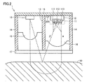
- FIG. 2 is a diagram showing a state where the biological information sensor of FIG. 1 is not in close contact with a human body. It is a functional block diagram for demonstrating the function of the biometric information sensor of FIG. It is a functional block diagram for demonstrating the function of the control apparatus in FIG. It is a functional block diagram for demonstrating the detail of the calculating part in FIG. It is a frequency spectrum figure which shows operation
- FIG. 1 is a cross-sectional view showing a configuration of biological information sensor 1 according to the first embodiment. Below, the case where the biometric information sensor 1 measures a heart rate as information regarding a living body will be described.
- the biological information sensor includes a light emitting unit 10 that is a white LED, a light receiving unit 11, light shielding walls 13 and 14, lenses 15 and 16, a transparent plate 17, a substrate 18, and a control device. 200.
- the light emitting unit 10, the light receiving unit 11, and the control device 200 are formed on the surface of the substrate 18.
- the light receiving unit 11 includes a silicon substrate 12 and a G sensor 111, a B sensor 112, and an R sensor 113 formed on the silicon substrate 12.
- the control device 200 may be formed on the silicon substrate 12.
- a light shielding wall 14 is formed so as to surround the light emitting unit 10 and the light receiving unit 11 and prevent external light from entering the light receiving unit 11.
- a light shielding wall 13 for preventing white light emitted from the light emitting unit 10 from directly entering the light receiving unit 11 is formed at the center of the surface of the substrate 18. That is, the space formed by the light shielding wall 14 is partitioned by the light shielding wall 13 into a space on the side where the light emitting unit 10 is located and a space on the side where the light receiving unit 11 is located.
- a lens 15 is provided in the emission direction of the light emitting unit 10, and a lens 16 is provided in the light receiving direction of the light receiving unit 11.
- the openings at the lower ends of the light shielding walls 13 and 14 are closed by a transparent plate 17.
- the surface of the transparent plate 17 is in close contact with the surface of the human body 50.
- the white light emitted from the light emitting unit 10 is irradiated to the human body 50 through the lens 15 and the transparent plate 17.
- the light ⁇ reflected inside the body enters the light receiving unit 11 through the transparent plate 17 and the lens 16.
- the G sensor 111 outputs a signal having a level corresponding to the intensity of green light in the light ⁇ .
- the B sensor 112 outputs a signal having a level corresponding to the intensity of blue light in the light ⁇ .
- the R sensor 113 outputs a signal having a level corresponding to the intensity of red light in the light ⁇ .
- the control device 200 determines whether the biological information sensor 1 is in close contact with the skin surface of the human body 50 based on the signal from the B sensor 112, and the biological information sensor 1 is in close contact with the skin surface of the human body 50.
- a signal indicating the heart rate is generated based on the signal from the G sensor 111 and the signal from the R sensor 113.
- the biological information sensor 1 when the biological information sensor 1 is in close contact with the human body 50, the light ⁇ reflected from the skin surface of the human body 50 is blocked by the light shielding wall 13 and hardly enters the light receiving unit 11.
- the biological information sensor 1 when the biological information sensor 1 is not in close contact with the human body 50 and there is a gap between the biological information sensor 1 and the skin surface of the human body 50, the light ⁇ is transmitted to the light receiving unit 11. Incidence can be noise in measuring heart rate.
- the biological information sensor 1 it is determined whether or not the biological information sensor 1 is in close contact with the human body 50 based on whether or not the intensity of the blue light incident on the light receiving unit is smaller than a predetermined threshold.
- the heart rate is calculated using the signal from the G sensor 111 and the signal from the R sensor 113 when the information sensor 1 is in close contact with the human body 50.
- the blue light emitted toward the human body is absorbed inside the human body and is therefore hardly reflected inside the human body, it is hardly included in the light ⁇ .
- the blue light is mainly reflected from the skin surface, and thus is included in the light ⁇ . Therefore, when the biological information sensor 1 is in close contact with the human body 50 as shown in FIG. 1, the blue light contained in the light ⁇ is blocked by the light shielding wall 13 and hardly enters the light receiving unit 11.
- the biological information sensor 1 is not in close contact with the human body 50 as shown in FIG. 2 and there is a gap between the biological information sensor 1 and the human body 50, the blue color reflected on the skin surface of the human body 50 is reflected. Light enters the light receiving unit 11 through the gap. Therefore, it is determined whether or not the biological information sensor 1 is in close contact with the human body 50 by measuring the intensity of the blue light incident on the light receiving unit 11.
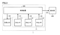
- control device 200 outputs control signal S0 to light emitting unit 10 in response to a measurement start instruction from the user.
- the light emitting unit 10 emits light in response to the control signal S0 becoming a predetermined level, and emits white light to the human body.
- the white light emitted from the light emitting unit 10 is reflected by the human body, and the reflected light enters the G sensor 111, the B sensor 112, and the R sensor 113.
- part of the white light is absorbed by the skin, blood, and the like, and therefore the intensity of the reflected light varies according to the pulse wave and body motion of the human body.
- the intensity of the green light included in the reflected light varies according to the pulse wave and body motion of the human body.
- the intensity of the red light contained in the reflected light varies according to the movement of the human body, but hardly varies according to the pulsation of the human body.
- most of the blue light included in the reflected light is reflected by the skin surface, and is used to determine whether or not the biological information sensor 1 is in close contact with the human body 50.
- the G sensor 111 generates a signal S1 having a level corresponding to the intensity of the incident green light out of the light emitted from the light emitting unit 10.
- the level (eg, voltage) of the signal S1 increases as the intensity of the incident green light increases.
- the level of the signal S1 changes according to the pulsation and body movement of the human body.
- the B sensor 112 generates a signal S2 having a level corresponding to the intensity of the incident blue light out of the light emitted from the light emitting unit 10.
- the level (eg, voltage) of the signal S2 increases as the intensity of the incident blue light increases.
- the R sensor 113 receives light reflected mainly from the human body out of the light emitted from the light emitting unit 10, and generates a signal S3 having a level corresponding to the intensity of the red light.
- the level (eg, voltage) of the signal S3 increases as the intensity of the incident red light increases.
- the signal S3 changes according to the movement of the human body, but hardly changes according to the pulsation of the human body.
- the control device 200 appropriately amplifies at least one of the signals S1 and S3 so that the amplitudes of the body motion components that change in the same period of the signals S1 and S3 are substantially the same, and the signal S1 A signal indicating a level difference from the signal S3 is calculated.
- the control device 200 generates a signal S4 indicating the pulse wave of the human body based on the signal indicating the level difference.
- the control device 200 outputs the signal S4 to the display unit 400 when the level of the signal S2 is less than a predetermined threshold (when the biological information sensor 1 is in close contact with the human body 50).
- Display unit 400 displays characters, images, and the like indicating the heart rate in accordance with signal S4 from control device 200. Communication between the control device 200 and the display unit 400 may be performed by wire or wirelessly.
- control device 200 includes amplifiers 211, 211, 231, AD (Analog-to-Digital) converters 212, 222, 232, high-pass filters (HPF) 213, 223, and so on. 233, the calculating part 30, the FFT (Fast Fourier Transform: Fast Fourier Transform) part 214,234, the heart rate extraction process part 22, and the control part 210 are included.
- AD Analog-to-Digital
- HPF high-pass filters
- the control unit 210 changes the control signal S0 alternately to the “H” level and the “L” level at a frequency sufficiently higher than the frequency of the pulse wave to turn on and off the light emitting unit 10 in a predetermined cycle, and control the control signal S0.
- the entire control apparatus 200 is controlled in synchronization with the signal S0.
- the G sensor 111 receives light emitted from the light emitting unit 10 and reflected mainly in the human body and light leaked from the outside according to body movement, and corresponds to the intensity of green light in the received light.
- a level signal S1 is output.
- the B sensor 112 receives light emitted from the light emitting unit 10 and reflected from the skin surface and light leaked from the outside in accordance with body movement, and has a level corresponding to the intensity of blue light in the received light.
- the signal S2 is output.
- the R sensor 113 receives the light emitted from the light emitting unit 10 and reflected in the human body and the light leaked from the outside in accordance with the body movement, and has a level corresponding to the intensity of the red light of the received light.
- the signal S3 is output.
- the amplifier 211 amplifies the signal S1 output from the G sensor 111.
- the AD converter 212 converts the output signal of the amplifier 211 into a digital signal.
- the high-pass filter 213 removes a direct current component from the output signal of the AD converter 212.
- the signal that has passed through the high-pass filter 213 is output to the arithmetic unit 30 as a digital signal D1.
- the amplifier 221 amplifies the signal S2 output from the B sensor 112.
- the AD converter 222 converts the output signal of the amplifier 221 into a digital signal.
- the high-pass filter 223 removes a direct current component from the output signal of the AD converter 222.
- the signal that has passed through the high-pass filter 223 is output to the arithmetic unit 30 as a digital signal D2.
- the amplifier 231 amplifies the signal S3 output from the R sensor 113.
- the AD converter 232 converts the output signal of the amplifier 231 into a digital signal.
- the high-pass filter 233 removes a direct current component from the output signal of the AD converter 232.
- the signal that has passed through the high-pass filter 233 is output to the arithmetic unit 30 as a digital signal D3.
- the arithmetic unit 30 includes memories 310, 320, 330, subtracters 311, 321, 331, 333, and an amplifier 332.
- the memory 310 temporarily stores the digital signal D1 in the time zone in which the control signal S0 is at the “L” level (that is, the time zone in which the light emitting unit 10 is turned off) as the digital signal D1D, and the control signal S0 is at the “H” level. After the digital signal D1 in the time zone (that is, the time zone in which the light emitting unit 10 is lit) is temporarily stored as the digital signal D1L, the digital signals D1D and D1L are output to the subtractor 311.
- the digital signal D1D includes a noise component caused by light leaking into the G sensor 111 from the outside during the time when the light emitting unit 10 is turned off. This noise component is also included in the digital signal D1L.
- the subtractor 311 subtracts the digital signal D1D from the digital signal D1L and outputs a digital signal DG. Therefore, the digital signal DG is a signal obtained by removing noise components from the digital signal D1L.
- the memory 320 temporarily stores the digital signal D2 in the time zone in which the control signal S0 is at the “L” level (that is, the time zone in which the light emitting unit 10 is turned off) as the digital signal D2D, and the control signal S0 is at the “H” level. After the digital signal D2 in the time zone (that is, the time zone in which the light emitting unit 10 is lit) is temporarily stored as the digital signal D2L, the digital signals D2D and D2L are output to the subtractor 321.
- the digital signal D2D includes a noise component caused by light leaking into the B sensor 112 from the outside during a time period when the light emitting unit 10 is turned off. This noise component is also included in the digital signal D2L.
- the subtractor 321 subtracts the digital signal D2D from the digital signal D2L and outputs the digital signal DB1 to the comparator 322. Therefore, the digital signal DB1 is a signal obtained by removing noise components from the digital signal D2L.
- the memory 320 stores a predetermined threshold value used for determining whether or not the biological information sensor 1 is in contact with the human body 50, and outputs a digital signal DB0 whose level is the threshold value to the comparator 322.
- the comparator 322 compares the level of the digital signal DB0 with the level of the digital signal DB1.
- the comparator 322 outputs the level of the digital signal DB as “H” when the level of the digital signal DB1 is less than the level of the digital signal DB0 (when the biological information sensor 1 is in close contact with the human body 50).
- the comparator 322 outputs the level of the digital signal DB as “L” when the level of the digital signal DB1 is equal to or higher than the level of the digital signal DB0 (when the biological information sensor 1 is not in close contact with the human body 50). .
- the memory 330 temporarily stores the digital signal D3 in the time zone in which the control signal S0 is at “L” level (that is, the time zone in which the light emitting unit 10 is turned off) as the digital signal D3D, and the control signal S0 is at “H” level. After the digital signal D3 in the time zone (that is, the time zone in which the light emitting unit 10 is lit) is temporarily stored as the digital signal D3L, the digital signals D3D and D3L are output to the subtractor 331.
- the digital signal D3D includes a noise component caused by light leaking into the R sensor 113 from the outside during a time period when the light emitting unit 10 is turned off. This noise component is also included in the digital signal D3L.
- the subtractor 331 subtracts the digital signal D3D from the digital signal D3L and outputs a digital signal DR. Therefore, the digital signal DR is a signal obtained by removing noise components from the digital signal D3L.
- the digital signal DG mainly includes a body motion component and a pulse wave component
- the digital signal DR mainly includes a body motion component.
- the amplifier 332 amplifies the digital signal DR so that the level of the body motion component included in the digital signal DG is approximately the same as the level of the body motion component included in the digital signal DR.
- the subtractor 333 subtracts the digital signal DR from the digital signal DG and outputs a digital signal DGR. Since the digital signal DGR is a signal obtained by subtracting the digital signal DR including the body motion component from the digital signal DG including the body motion component and the pulse wave component, it can be said to be a signal mainly including the pulse wave component.
- the digital signal DR is amplified by the amplifier 332.
- the present invention is not limited to this, and the levels of body motion components included in the digital signals DG and DR are approximately the same. At least one of the digital signals DG and DR may be amplified or attenuated.
- the FFT unit 214 performs fast Fourier transform on the digital signal DG when the level of the digital signal DB is “H” (when the biological information sensor 1 is in close contact with the human body 50).
- the frequency spectrum of the digital signal DG is generated and output to the heartbeat extraction processing unit 22.
- the FFT unit 214 does not output when the level of the digital signal DB is “L” (when the biological information sensor 1 is not in close contact with the human body 50).
- the FFT unit 234 When the level of the digital signal DB is “H”, the FFT unit 234 performs fast Fourier transform on the digital signal DGR, generates a frequency spectrum of the digital signal DGR, and outputs the frequency spectrum to the heartbeat extraction processing unit 22. The FFT unit 234 does not output when the level of the digital signal DB is “L”.
- the heart rate extraction processing unit 22 calculates the heart rate of the human body based on the frequency spectrum output from the FFT units 214 and 234, and outputs a signal S4 indicating the obtained heart rate to the display unit 400.
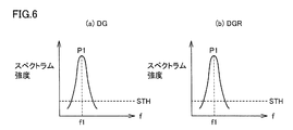
- FIGS. 6A and 7A show the frequency spectrum of the digital signal DG generated by the FFT unit 214 (see FIG. 4).
- FIGS. 6B and 7B show the FFT unit 234 (see FIG. 6).
- 4) is a frequency spectrum of the digital signal DGR generated in (4).
- a peak frequency existing in a range where the spectrum intensity is equal to or greater than a predetermined threshold STH is a pulse wave frequency candidate.
- the digital signal DG contains almost no body movement component. That is, since the digital signal DG and the digital signal DGR are almost the same signal, as shown in FIGS. 6A and 6B, the frequency spectrums of the digital signals DG and DGR are both the same, and one peak P1 is obtained. It becomes a mountain-shaped curve.
- the heartbeat extraction processing unit 22 determines that the frequency f1 of the peak P1 is the frequency of the pulse wave.
- the heartbeat extraction processing unit 22 calculates a heart rate [times / minute] based on the frequency f1, and outputs a signal S4 indicating the heart rate [times / minute] to the display unit 400.
- the frequency spectra of the digital signals DG and DGR both have two peaks P1. , P2 in many cases.
- the digital signal DG mainly includes a body motion component and a pulse wave component
- the digital signal DGR is a signal mainly including a pulse wave component. That is, it can be said that the body motion component of the digital signal DGR is smaller than that of the digital signal DG.
- the heart rate extraction processing unit 22 calculates a rate (decrease rate) in which the heights of the peak P1 and P2 of the frequency spectrum of the digital signal DGR are reduced compared to the heights of the peaks P1 and P2 of the frequency spectrum of the digital signal DG. calculate.
- the heartbeat extraction processing unit 22 determines the frequency f2 of the peak with the larger decrease rate (P2 in this case) as the body motion frequency, and uses the frequency f1 of the peak with the smaller decrease rate (P1 in this case) as the pulse. Judge as the frequency of the wave.
- the heartbeat extraction processing unit 22 calculates a heart rate [times / minute] based on the frequency f1, and outputs a signal S4 indicating the heart rate [times / minute] to the display unit 400.
- the biological information sensor 1 whether or not the biological information sensor 1 is in close contact with the surface of the human body 50 is determined based on the intensity of the blue light reflected from the skin surface of the human body 50.
- the heart rate can be calculated based on a signal with less noise when the biological information sensor 1 is in close contact with the human body 50, and as a result, the measurement accuracy can be increased.
- FIG. 8 is a cross-sectional view showing the configuration of the biological information sensor 1A used in the confirmation experiment of the first embodiment.
- the biological information sensor 1A is different from the biological information sensor 1 in that the biological information sensor 1A does not include a transparent plate, and the end of the light shielding wall and the skin surface of the human body when the biological information sensor 1A is attached to the human body. The distance between and is variable. Since the other configuration of the biological information sensor 1A is the same as that of the biological information sensor 1, the description of the same configuration will not be repeated.
- the biological information sensor 1A includes a light shielding wall 13A.
- the distance between the end of the light shielding wall 13A on the human body 50 side and the skin surface of the human body 50 (hereinafter also referred to as “raising distance d”) is variable. .
- the biological information sensor 1A When the biological information sensor 1A is attached to the human body 50, the light reflected from the skin surface of the human body 50 out of the light emitted from the light emitting unit 10 is less likely to enter the light receiving unit 11 as the raised distance d is smaller. Become. On the contrary, the larger the raised distance d, the easier it is to enter the light receiving unit 11. That is, the case where the raising distance d is small in the biological information sensor 1A corresponds to the case where the biological information sensor 1 according to the first embodiment is in close contact with the human body. On the other hand, when the raising distance d is large in the biological information sensor 1A, this corresponds to the case where the biological information sensor 1 is not in close contact with the human body.
- FIG. 9 is a diagram illustrating the relationship between the raising distance d and the intensity of green light, the intensity of red light, and the intensity of blue light incident on the light receiving unit 11.
- the output (ADC count) of an AD converter (see FIG. 4) that converts the signal output from the light receiving unit 11 into a digital signal increases. Therefore, in FIG. 9, the relationship between the raising distance d and the intensity of each light is shown as the relationship between the raising distance d and the ADC count corresponding to each light.
- the ADC count corresponding to each light when the lifting distance is 1 mm, 2 mm, 3 mm, and 4 mm is plotted, and each point is connected by a straight line.
- the plot point G represents the relationship between the raised distance d and the ADC count corresponding to the green light incident on the light receiving unit 11.
- Plot point B represents the relationship between the raised distance d and the ADC count corresponding to the blue light.
- the plot point R represents the relationship between the raised distance d and the ADC count corresponding to red light.
- the intensity of the green light, the intensity of the blue light, and the intensity of the red light incident on the light receiving unit 11 hardly change.
- the intensity of the blue light incident on the light receiving unit 11 is significantly increased as compared with the intensity of the green light and the intensity of the red light.
- the lifting distance d is 4 mm, the intensity of each light is almost the same as when the lifting distance d is 3 mm.
- the biological information sensor 1 according to the first embodiment and the human body 50 are not in close contact with each other and a gap is generated between the biological information sensor 1 and the human body 50, the light shielding wall is blocked while the contact is made. Since blue light enters the light receiving unit 11 through the gap, the blue light incident on the light receiving unit 11 should increase rapidly. In FIG. 9, the intensity of the blue light incident on the light receiving unit 11 increases rapidly while the raising distance d is from 2 mm to 3 mm. Therefore, when the CTH that is the ADC count corresponding to the raised distance d0 (2 ⁇ d0 ⁇ 3) is set as a threshold, and the blue light ADC count is equal to or greater than the threshold CTH, the biological information sensor 1 is in close contact with the human body 50. It is treated as a case corresponding to the case where there is not.
- FIG. 10 is a diagram showing a frequency spectrum generated by the FFT unit 214 or the FFT unit 234 (see FIG. 4). 10 (a), (b), (c), and (d) show cases where the lifting distance is 0 mm, 1 mm, 2 mm, and 3 mm, respectively.
- the peak frequency existing in the range of the spectrum intensity equal to or higher than the predetermined threshold value STH is a pulse wave frequency candidate.
- 10 (a), 10 (b), 10 (c), and 10 (d) are data when the biological information sensor 1A is mounted on a stationary human body 50.
- FIG. Therefore, these data contain almost no body motion component and mainly contain a pulse wave component. Therefore, the frequency spectra generated by the FFT unit 214 and the FFT unit 234 have almost the same shape, and the peak existing in the range above the threshold value STH should be only the pulse wave component.
- the peak that exists in the range of the threshold value STH or more is only the peak P1. Therefore, the frequency f1 is a pulse wave frequency.
- peaks existing in a range equal to or higher than the threshold value STH are peaks P1, P2, P3, and P4. Therefore, it is impossible to specify which of the frequencies f1, f2, f3, and f4 corresponding to each of them is a pulse wave frequency, and the heart rate cannot be extracted from FIG.
- the frequency spectra shown in FIGS. 10A, 10 ⁇ / b> B, and 10 ⁇ / b> C are generated based on data with less noise when the biological information sensor 1 is in close contact with the human body 50. Although it corresponds to a spectrum, it can be said to be data to be used when extracting a heart rate.
- the frequency spectrum of FIG. 10D corresponds to the frequency spectrum generated based on the data including the reflected light from the skin surface of the human body as noise because the biological information sensor 1 is not in close contact with the human body 50. No, it should not be used when extracting heart rate.
- the ADC count of blue light is less than the threshold value CTH when the raising distance is 0 mm, 1 mm, and 2 mm, which are shown in FIGS. Each corresponds to (c).
- the ADC count of blue light is equal to or greater than the threshold CTH when the raising distance is equal to or greater than d0, which corresponds to FIG. Therefore, by treating the case where the ADC count of blue light is equal to or greater than the threshold CTH as the case where the biological information sensor 1 is not in close contact with the human body 50, noise generated when the biological information sensor 1 is in close contact with the human body 50 is treated.
- the heart rate can be calculated based on a small amount of data. As a result, the measurement accuracy of the biological information sensor 1 can be increased.
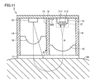
- the heart rate is measured using the G sensor, the B sensor, and the R sensor. Even without the R sensor, the heart rate can be measured with the G sensor and the B sensor.
- the light receiving unit 21 does not include the R sensor and the G sensor 111 and the B sensor 112 measure the heart rate. I do not care.
- the biological information sensor 2 also determines whether the biological information sensor 2 is in close contact with the surface of the human body 50 based on the intensity of the blue light reflected from the skin surface of the human body and incident on the light receiving unit 21.
- the heart rate can be calculated based on a signal with less noise when the sensor 2 is in close contact with the human body 50, and as a result, the measurement accuracy can be increased.
- the biological information sensor 2 is slightly inferior in heart rate measurement accuracy compared to the biological information sensor 1 because the light receiving unit 21 does not include an R sensor.
- the manufacturing cost of the biological information sensor 2 can be made lower than that of the biological information sensor 1 by the amount that the R sensor is unnecessary. Therefore, the biological information sensor 2 can be appropriately selected from the viewpoint of a balance between required measurement accuracy and manufacturing cost.
- the heart rate is measured as the information related to the living body, but the information related to the living body is not limited to the heart rate, and may be, for example, the blood oxygen saturation concentration.
- the light emitting unit 10 that emits white light is used.
- a green LED that emits green light and a blue LED that emits blue light may be provided instead of the light emitting unit 10, and as necessary.
- a red LED that emits red light may be provided.
- the biological information sensor according to the above-described embodiment, it is possible to detect the heart rate of a living body including not only a human body but also a human and an animal.
- 1, 1A, 2 biological information sensor 10 light emitting unit, 11, 21 light receiving unit, 12 silicon substrate, 13, 13A, 14 shading wall, 15, 16 lens, 17 transparent plate, 18 substrate, 22 heart rate extraction processing unit, 30 Arithmetic unit, 50 human body, 111, 112, 113 sensor, 200 control device, 210 control unit, 211, 221, 231, 332 amplifier, 212, 222, 232 AD converter, 213, 223, 233 high-pass filter, 214, 234 part, 310, 320, 330 memory, 311, 321, 331, 333 subtractor, 322 comparator, 400 display part, B, G, R plot points, CTH, STH threshold, D1L, D1, D1D, D2D, D2L , D2, D3L, D3, D3D, DB, DB0, DB1, DG, DGR DR digital signal, P1, P2, P3, P4 peaks, S0 control signal, S1, S2, S3, S4 signal, T1 period, d, d0 raising distance,
Landscapes
- Health & Medical Sciences (AREA)
- Life Sciences & Earth Sciences (AREA)
- Engineering & Computer Science (AREA)
- Surgery (AREA)
- General Health & Medical Sciences (AREA)
- Biophysics (AREA)
- Pathology (AREA)
- Veterinary Medicine (AREA)
- Biomedical Technology (AREA)
- Heart & Thoracic Surgery (AREA)
- Medical Informatics (AREA)
- Molecular Biology (AREA)
- Public Health (AREA)
- Animal Behavior & Ethology (AREA)
- Physics & Mathematics (AREA)
- Cardiology (AREA)
- Physiology (AREA)
- Signal Processing (AREA)
- Dentistry (AREA)
- Oral & Maxillofacial Surgery (AREA)
- Artificial Intelligence (AREA)
- Computer Vision & Pattern Recognition (AREA)
- Psychiatry (AREA)
- Computer Networks & Wireless Communication (AREA)
- Measuring Pulse, Heart Rate, Blood Pressure Or Blood Flow (AREA)
- Measurement Of The Respiration, Hearing Ability, Form, And Blood Characteristics Of Living Organisms (AREA)
Abstract
測定精度を上げることができる生体情報センサを提供する。発光部(10)は、第1の光と第2の光とを含む光を出射する。受光部(11)は、入射した光の強度に応じたレベルの信号を出力する。生体情報センサ(1)が生体(50)に装着された場合、発光部(10)から出射された光は、生体(50)で反射して受光部(11)へ入射する。第1の光センサ(111)は、入射した第1の光の強度に応じたレベルの第1の信号を出力する。第2の光センサ(112)は、入射した第2の光の強度に応じたレベルの第2の信号を出力する。制御装置(200)は、第2の信号に基づいて生体情報センサ(1)と生体(50)の表面とが密着しているか否かを判定する。制御装置(200)は、生体情報センサ(1)と生体(50)の表面とが密着している場合の第1の信号に基づいて生体(50)に関連する情報を生成する。
Description
本発明は生体情報センサに関し、特にウェアラブルな生体情報センサに関する。
従来からウェアラブルな生体情報センサが知られている。例えば、特開2012-143316(特許文献1)には、ウェアラブルな生体情報センサが開示されている。当該生体情報センサは、第1および第2の光センサと演算回路とを備える。第1の光センサは、第1の発強度の光を生体に出射する第1の発光部と、第1の発光部の出射光が生体内で反射した光を受けて第1の受光信号を生成する第1の受光部とを含む。第2の光センサは、第1の発強度よりも弱い第2の発強度の光を生体に出射する第2の発光部と、第2の発光部の出射光が生体内で反射した光を受けて第2の受光信号を生成する第2の受光部とを含む。演算回路は、第1の受光信号から第2の受光信号を差し引いて脈波データを取得する。
使用者が生体情報センサを身体に装着して運動しながら心拍数のような生体情報を測定する場合、或いは使用者が生体情報センサを身体に誤装着した場合、生体情報センサと身体の表面との間に隙間が生じるときがある。このような隙間が生じると、生体の内部で反射した光だけではなく生体の表面で反射した光も生体情報センサの受光部へ入射してしまう。例えば、心拍数を測定する場合、必要なのは生体の内部からの反射光であるため、生体の表面からの反射光は心拍数を算出するにあたってノイズとなり、測定精度の悪化を招くおそれがある。
それゆえに、本発明の主たる目的は、測定精度を上げることができる生体情報センサを提供することである。
本発明に係る生体情報センサは、生体に装着されて当該生体に関連する情報を生成する。生体情報センサは、発光部と、受光部と、制御装置とを備える。発光部は、第1の光と第2の光とを含む光を出射する。受光部は、第1の光センサと第2の光センサとを含み、入射した光の強度に応じたレベルの信号を出力する。制御装置は、受光部から出力される信号を受けて生体に関連する情報を生成する。生体情報センサが生体に装着された場合、発光部から出射された光は、当該生体で反射して受光部へ入射する。第1の光センサは、入射した第1の光の強度に応じたレベルの第1の信号を出力する。第2の光センサは、入射した第2の光の強度に応じたレベルの第2の信号を出力する。制御装置は、第2の信号に基づいて生体情報センサと生体の表面とが密着しているか否かを判定する。制御装置は、生体情報センサと生体の表面とが密着している場合の第1の信号に基づいて生体に関連する情報を生成する。
このような構成により、生体情報センサが生体に密着している場合のノイズの少ない信号に基づいて生体に関連する情報を算出できる。その結果、生体情報センサは測定精度を上げることができる。
好ましくは、制御装置は、第2の信号のレベルが所定の閾値より小さい場合に生体情報センサと生体の表面とが密着していると判定する。
好ましくは、発光部が出射する光は、第3の光をさらに含む。受光部は、第3の光センサをさらに含む。第3の光センサは、入射した第3の光の強度に応じたレベルの第3の信号を出力する。制御装置は、生体情報センサと生体の表面とが密着している場合の、第1の信号および第3の信号に基づいて生体に関連する情報を生成する。
好ましくは、制御装置は、第1の信号のレベルと第3の信号のレベルとの差に基づいて生体に関する情報を生成する。
好ましくは、第1の光は、緑色光である。第2の光は、青色光である。第3の光は、赤色光である。
好ましくは、基板と、第1の遮光壁と、第2の遮光壁とをさらに備える。基板は、発光部、受光部、および制御装置が形成されている。第1の遮光壁は、基板の外周に沿って、発光部および受光部を囲むように形成されている。第2の遮光壁は、基板と第1の遮光壁とによって形成された空間を、発光部がある側の空間と受光部がある側の空間とに仕切っている。
好ましくは、生体に関する情報は、心拍数である。
好ましくは、発光部は、白色光を出射する発光ダイオードである。
好ましくは、発光部は、白色光を出射する発光ダイオードである。
本発明に係る生体情報センサは、生体情報センサが生体の表面に密着しているか否かを生体からの反射光に含まれる第2の光に基づいて判定する。本発明に係る生体情報センサは、当該判定に基づいて生体情報センサが生体の表面に密着している場合のノイズの少ない信号に基づいて生体に関する情報を生成することができ、その結果、測定精度を上げることができる。
以下、本発明の実施の形態について、図面を参照しながら詳細に説明する。なお、図中同一または相当部分には同一符号を付してその説明は繰り返さない。
[第1の実施の形態]
図1は、第1の実施の形態に従う生体情報センサ1の構成を示す断面図である。以下では、生体情報センサ1が生体に関する情報として心拍数を測定する場合について説明する。
図1は、第1の実施の形態に従う生体情報センサ1の構成を示す断面図である。以下では、生体情報センサ1が生体に関する情報として心拍数を測定する場合について説明する。
図1を参照して、生体情報センサは、白色LEDである発光部10と、受光部11と、遮光壁13,14と、レンズ15,16と、透明板17と、基板18と、制御装置200とを備える。
基板18の表面には発光部10と受光部11と制御装置200とが形成されている。受光部11は、シリコン基板12と、シリコン基板12に形成されたGセンサ111、Bセンサ112およびRセンサ113とを含む。制御装置200は、シリコン基板12に形成されていても構わない。
基板18の表面の縁には、発光部10および受光部11を囲むようにして、外部光が受光部11に入射するのを防止するための遮光壁14が形成されている。基板18の表面の中央には、発光部10から出射された白色光が受光部11に直接入射するのを防止するための遮光壁13が形成されている。つまり、遮光壁14によって形成された空間が、発光部10がある側の空間と受光部11がある側の空間とに遮光壁13によって仕切られている。
発光部10の出射方向にレンズ15が設けられ、受光部11の受光方向にレンズ16が設けられている。遮光壁13,14の下端の開口部は透明板17によって閉じられている。心拍数を測定する場合は、透明板17の表面が人体50の表面に密着される。
発光部10から出射された白色光は、レンズ15および透明板17を介して人体50に照射される。当該白色光のうち体内で反射した光αは、透明板17およびレンズ16を介して受光部11に入射する。Gセンサ111は、光αのうちの緑色光の強度に応じたレベルの信号を出力する。Bセンサ112は、光αのうちの青色光の強度に応じたレベルの信号を出力する。Rセンサ113は、光αのうちの赤色光の強度に応じたレベルの信号を出力する。制御装置200は、Bセンサ112からの信号に基づいて生体情報センサ1が人体50の皮膚表面に密着しているか否かを判定するとともに、生体情報センサ1が人体50の皮膚表面に密着している場合の、Gセンサ111からの信号およびRセンサ113からの信号に基づいて心拍数を示す信号を生成する。
図1に示すように生体情報センサ1が人体50に密着している場合、人体50の皮膚表面で反射した光βは遮光壁13に遮られ、受光部11に入射することがほとんどない。
一方、図2に示すように生体情報センサ1が人体50に密着しておらず、生体情報センサ1と人体50の皮膚表面との間に隙間が生じている場合、光βは受光部11に入射し、心拍数を測定するにあたってのノイズとなり得る。
そこで、第1の実施の形態においては、受光部に入射する青色光の強度が所定の閾値よりも小さいか否かによって生体情報センサ1が人体50に密着しているか否かを判定し、生体情報センサ1が人体50に密着している場合の、Gセンサ111からの信号およびRセンサ113からの信号を用いて心拍数を算出する。
人体に向けて出射された青色光は、人体の内部では吸収されるため人体に内部で反射されることがほとんどないため、光αにはほとんど含まれない。当該青色光は、主に皮膚表面で反射されるため、光βに含まれる。したがって、図1のように生体情報センサ1が人体50に密着している場合には、光βに含まれる青色光は遮光壁13に遮られて受光部11にほとんど入射しない。一方、図2のように生体情報センサ1が人体50に密着しておらず、生体情報センサ1と人体50との間に隙間が生じている場合には、人体50の皮膚表面で反射した青色光は当該隙間を通って受光部11に入射する。したがって、受光部11に入射した青色光の強度を測定することによって生体情報センサ1が人体50と密着しているか否かを判定する。
図3を用いて生体情報センサ1の機能構成について説明する。図3を参照して、制御装置200は、使用者からの測定開始指示に応じて発光部10に制御信号S0を出力する。発光部10は、制御信号S0が所定のレベルとなったことに応答して発光して白色光を人体に出射する。発光部10から出射された白色光は人体で反射されてその反射光がGセンサ111、Bセンサ112およびRセンサ113に入射する。このとき白色光のうちの一部は皮膚、血液などに吸収されるため、反射光の強度は人体の脈波および体動に応じて変動する。具体的には、反射光に含まれる緑色光の強度は、人体の脈波および体動に応じて変動する。反射光に含まれる赤色光の強度は、人体の体動に応じて変動するが人体の脈動に応じてはほとんど変動しない。反射光に含まれる青色光は、上述したようにそのほとんどが皮膚表面で反射された光であり、生体情報センサ1が人体50に密着しているか否かの判定に使用される。
Gセンサ111は、発光部10から出射された光のうち、入射した緑色光の強度に応じたレベルの信号S1を生成する。信号S1のレベル(たとえば電圧)は、入射した緑色光の強度が強くなるにつれて増大する。上述したように、信号S1のレベルは、人体の脈動および体動に応じて変化する。
Bセンサ112は、発光部10から出射された光のうち、入射した青色光の強度に応じたレベルの信号S2を生成する。信号S2のレベル(たとえば電圧)は、入射した青色光の強度が強くなるにつれて増大する。
Rセンサ113は、発光部10から出射された光のうち、主に人体内で反射した光を受け、そのうちの赤色光の強度に応じたレベルの信号S3を生成する。信号S3のレベル(たとえば電圧)は、入射した赤色光の強度が強くなるにつれて増大する。上述したように、信号S3は、人体の体動に応じて変化するが、人体の脈動に応じてほとんど変化しない。
制御装置200は、信号S1,S3のうちの同じ周期で変動する体動成分の振幅が略同じになるように信号S1,S3のうちの少なくともいずれか一方の信号を適宜増幅し、信号S1と信号S3とのレベル差を示す信号を算出する。制御装置200は、当該レベル差を示す信号に基づいて人体の脈波を示す信号S4を生成する。制御装置200は、信号S2のレベルが所定の閾値未満である場合(生体情報センサ1が人体50に密着している場合)に信号S4を表示部400に出力する。表示部400は、制御装置200からの信号S4に従って心拍数を示す文字、画像などを表示する。制御装置200と表示部400との通信は有線で行なってもよいし、無線で行なってもよい。
図4を用いて制御装置200の機能構成について説明する。図4を参照して、制御装置200は、アンプ211,221,231、AD(Analog-to-Digital)コンバータ212,222,232、高域通過フィルタ(HPF:High-pass filter)213,223,233、演算部30、FFT(Fast Fourier Transform:高速フーリエ変換)部214,234、心拍抽出処理部22、および制御部210を含む。
制御部210は、脈波の周波数よりも十分に高い周波数で制御信号S0を交互に「H」レベルおよび「L」レベルに変化させて発光部10を所定の周期で点灯および消灯させるとともに、制御信号S0に同期して制御装置200全体を制御する。
Gセンサ111は、発光部10から出射されて主に人体内で反射した光と、体動に応じて外部から漏れ込んだ光とを受け、受けた光のうちの緑色光の強度に応じたレベルの信号S1を出力する。
Bセンサ112は、発光部10から出射されて皮膚表面で反射した光と、体動に応じて外部から漏れ込んだ光とを受け、受けた光のうちの青色光の強度に応じたレベルの信号S2を出力する。
Rセンサ113は、発光部10から出射されて人体内で反射した光と、体動に応じて外部から漏れ込んだ光とを受け、受けた光のうちの赤色光の強度に応じたレベルの信号S3を出力する。
アンプ211は、Gセンサ111から出力された信号S1を増幅する。ADコンバータ212は、アンプ211の出力信号をデジタル信号に変換する。高域通過フィルタ213は、ADコンバータ212の出力信号のうちの直流成分を除去する。高域通過フィルタ213を通過した信号は、デジタル信号D1として演算部30に出力される。
アンプ221は、Bセンサ112から出力された信号S2を増幅する。ADコンバータ222は、アンプ221の出力信号をデジタル信号に変換する。高域通過フィルタ223は、ADコンバータ222の出力信号のうちの直流成分を除去する。高域通過フィルタ223を通過した信号は、デジタル信号D2として演算部30に出力される。
アンプ231は、Rセンサ113から出力された信号S3を増幅する。ADコンバータ232は、アンプ231の出力信号をデジタル信号に変換する。高域通過フィルタ233は、ADコンバータ232の出力信号のうちの直流成分を除去する。高域通過フィルタ233を通過した信号は、デジタル信号D3として演算部30に出力される。
演算部30は、図5に示すように、メモリ310,320,330、減算器311,321,331,333、およびアンプ332を含む。
メモリ310は、制御信号S0が「L」レベルである時間帯(すなわち発光部10が消灯している時間帯)におけるデジタル信号D1をデジタル信号D1Dとして一旦記憶し、制御信号S0が「H」レベルである時間帯(すなわち発光部10が点灯している時間帯)におけるデジタル信号D1をデジタル信号D1Lとして一旦記憶した後、デジタル信号D1D,D1Lを減算器311に出力する。
デジタル信号D1Dは、発光部10が消灯している時間帯に外部からGセンサ111に漏れ込んだ光などに起因するノイズ成分を含む。このノイズ成分はデジタル信号D1Lにも含まれている。減算器311は、デジタル信号D1Lからデジタル信号D1Dを減算してデジタル信号DGを出力する。したがって、デジタル信号DGは、デジタル信号D1Lからノイズ成分が除去された信号となる。
メモリ320は、制御信号S0が「L」レベルである時間帯(すなわち発光部10が消灯している時間帯)におけるデジタル信号D2をデジタル信号D2Dとして一旦記憶し、制御信号S0が「H」レベルである時間帯(すなわち発光部10が点灯している時間帯)におけるデジタル信号D2をデジタル信号D2Lとして一旦記憶した後、デジタル信号D2D,D2Lを減算器321に出力する。
デジタル信号D2Dは、発光部10が消灯している時間帯に外部からBセンサ112に漏れ込んだ光などに起因するノイズ成分を含む。このノイズ成分はデジタル信号D2Lにも含まれている。減算器321は、デジタル信号D2Lからデジタル信号D2Dを減算してデジタル信号DB1を比較器322に出力する。したがって、デジタル信号DB1は、デジタル信号D2Lからノイズ成分が除去された信号となる。
メモリ320は、生体情報センサ1が人体50に接触しているか否かの判定に用いる所定の閾値を記憶しており、レベルが当該閾値であるデジタル信号DB0を比較器322に出力する。
比較器322は、デジタル信号DB0のレベルとデジタル信号DB1のレベルとを比較する。比較器322は、デジタル信号DB1のレベルがデジタル信号DB0のレベル未満であった場合(生体情報センサ1が人体50に密着している場合)にはデジタル信号DBのレベルを「H」として出力する。比較器322は、デジタル信号DB1のレベルがデジタル信号DB0のレベル以上であった場合(生体情報センサ1が人体50に密着してない場合)にはデジタル信号DBのレベルを「L」として出力する。
メモリ330は、制御信号S0が「L」レベルである時間帯(すなわち発光部10が消灯している時間帯)におけるデジタル信号D3をデジタル信号D3Dとして一旦記憶し、制御信号S0が「H」レベルである時間帯(すなわち発光部10が点灯している時間帯)におけるデジタル信号D3をデジタル信号D3Lとして一旦記憶した後、デジタル信号D3D,D3Lを減算器331に出力する。
デジタル信号D3Dは、発光部10が消灯している時間帯に外部からRセンサ113に漏れ込んだ光などに起因するノイズ成分を含む。このノイズ成分はデジタル信号D3Lにも含まれている。減算器331は、デジタル信号D3Lからデジタル信号D3Dを減算してデジタル信号DRを出力する。したがって、デジタル信号DRは、デジタル信号D3Lからノイズ成分が除去された信号となる。
デジタル信号DGは体動成分と脈波成分とを主に含み、デジタル信号DRは体動成分を主に含む。アンプ332は、デジタル信号DGに含まれる体動成分のレベルとデジタル信号DRに含まれる体動成分のレベルとが同程度になるようにデジタル信号DRを増幅する。減算器333は、デジタル信号DGからデジタル信号DRを減算してデジタル信号DGRを出力する。デジタル信号DGRは、体動成分と脈波成分とを含むデジタル信号DGから体動成分を含むデジタル信号DRを差し引いた信号であるから、脈波成分を主に含む信号といえる。
なお、図5に示した演算部30では、アンプ332によってデジタル信号DRを増幅したが、これに限るものではなく、デジタル信号DG,DRに含まれる体動成分のレベルが同程度になるようにデジタル信号DG,DRのうちの少なくともいずれか一方を増幅または減衰させてもよい。
再び図4を参照して、FFT部214は、デジタル信号DBのレベルが「H」である場合(生体情報センサ1が人体50に密着している場合)に、デジタル信号DGに高速フーリエ変換を施し、デジタル信号DGの周波数スペクトルを生成して心拍抽出処理部22に出力する。FFT部214は、デジタル信号DBのレベルが「L」である場合(生体情報センサ1が人体50に密着していない場合)には出力をしない。
FFT部234は、デジタル信号DBのレベルが「H」である場合、デジタル信号DGRに高速フーリエ変換を施し、デジタル信号DGRの周波数スペクトルを生成して心拍抽出処理部22に出力する。FFT部234は、デジタル信号DBのレベルが「L」である場合には出力をしない。
心拍抽出処理部22は、FFT部214,234から出力された周波数スペクトルに基づいて人体の心拍数を算出し、得られた心拍数を示す信号S4を表示部400に出力する。
図6および図7を用いて心拍抽出処理部22の動作について説明する。図6(a)および図7(a)はFFT部214(図4参照)で生成されたデジタル信号DGの周波数スペクトルであり、図6(b)および図7(b)はFFT部234(図4参照)で生成されたデジタル信号DGRの周波数スペクトルである。スペクトル強度が予め定められた閾値STH以上の範囲に存在するピークの周波数が脈波の周波数の候補となる。
体動が小さい場合(たとえば使用者が静止している場合)は、デジタル信号DGは体動成分をほとんど含まない。すなわち、デジタル信号DGとデジタル信号DGRはほとんど同じ信号となるため、図6(a),(b)に示すようにデジタル信号DG,DGRの周波数スペクトルはともに同形となって、1つのピークP1を持つ山型の曲線となる。この場合、心拍抽出処理部22は、ピークP1の周波数f1が脈波の周波数であると判定する。心拍抽出処理部22は、周波数f1に基づいて心拍数[回/分]を算出し、その心拍数[回/分]を示す信号S4を表示部400へ出力する。
体動が無視できない程度に生じる場合(たとえば使用者がジョギングしている場合)は、図7(a),(b)に示すように、デジタル信号DG,DGRの周波数スペクトルはともに2つのピークP1,P2を持つ山型の曲線となることが多い。先に説明したように、デジタル信号DGは体動成分と脈波成分とを主に含み、デジタル信号DGRは脈波成分を主に含んだ信号である。すなわち、デジタル信号DGRはデジタル信号DGに比べて体動成分が減少しているといえる。そこで、心拍抽出処理部22は、デジタル信号DGの周波数スペクトルのピークP1,P2の高さと比較してデジタル信号のDGRの周波数スペクトルのピークP1,P2の高さが減少した割合(減少率)を算出する。心拍抽出処理部22は、減少率が大きい方のピーク(この場合はP2)の周波数f2を体動の周波数と判定し、減少率が小さい方のピーク(この場合はP1)の周波数f1を脈波の周波数と判定する。心拍抽出処理部22は、周波数f1に基づいて心拍数[回/分]を算出し、その心拍数[回/分]を示す信号S4を表示部400へ出力する。
以上のように、生体情報センサ1によれば、生体情報センサ1が人体50の表面に密着しているか否かを人体50の皮膚表面から反射してくる青色光の強度に基づいて判定することによって生体情報センサ1が人体50に密着している場合のノイズの少ない信号に基づいて心拍数を算出することができ、その結果、測定精度を上げることができる。
[第1の実施の形態の確認実験]
第1の実施の形態においては、受光部11に入射する青色光に基づいて生体情報センサ1が人体50に密着しているか否かを判定した。本願発明者らは、受光部11へ入射する青色光を意図的に調整して、生体情報センサ1が人体50と密着していない場合を擬似的に再現することにより、受光部11へ入射する青色光に基づいて生体情報センサ1が人体50と密着しているか否かの判定が可能であることを確認する実験を行なった。以下では当該確認実験について説明する。
第1の実施の形態においては、受光部11に入射する青色光に基づいて生体情報センサ1が人体50に密着しているか否かを判定した。本願発明者らは、受光部11へ入射する青色光を意図的に調整して、生体情報センサ1が人体50と密着していない場合を擬似的に再現することにより、受光部11へ入射する青色光に基づいて生体情報センサ1が人体50と密着しているか否かの判定が可能であることを確認する実験を行なった。以下では当該確認実験について説明する。
図8は、第1の実施の形態の確認実験に使用した生体情報センサ1Aの構成を示す断面図である。生体情報センサ1Aが生体情報センサ1と異なる点は、生体情報センサ1Aは透明板を備えていないということと、生体情報センサ1Aを人体に装着した場合の遮光壁の端部と人体の皮膚表面との距離が可変であるということである。生体情報センサ1Aの他の構成については生体情報センサ1と同様のため、同様の構成については説明を繰り返さない。
図8を参照して、生体情報センサ1Aは、遮光壁13Aを備える。生体情報センサ1Aが人体50に装着された場合の遮光壁13Aの人体50側の端部と人体50の皮膚表面との距離(以下では、「かさ上げ距離d」ともいう。)は可変である。
生体情報センサ1Aが人体50に装着された場合、発光部10から出射された光のうち、人体50の皮膚表面で反射した光は、かさ上げ距離dが小さい程、受光部11へ入射し難くなる。逆に、かさ上げ距離dが大きい程、受光部11へ入射し易くなる。すなわち、生体情報センサ1Aにおいてかさ上げ距離dが小さい場合は、第1の実施の形態に従う生体情報センサ1が人体に密着している場合に対応する。一方、生体情報センサ1Aにおいてかさ上げ距離dが大きい場合は、生体情報センサ1が人体に密着していない場合に対応する。
図9は、かさ上げ距離dと、受光部11へ入射する緑色光の強度、赤色光の強度および青色光の強度との各々の関係を示す図である。受光部11へ入射する各光の強度が大きくなる程、受光部11から出力された信号をデジタル信号に変換するADコンバータ(図4参照)の出力(ADCカウント)は大きくなる。そのため、図9においては、かさ上げ距離dと各光の強度の関係を、かさ上げ距離dと各光に対応するADCカウントの関係として示している。図9においては、かさ上げ距離が1mm、2mm、3mmおよび4mmの場合の各光に対応するADCカウントをプロットし、各点を直線で結んでいる。プロット点Gはかさ上げ距離dと受光部11へ入射する緑色光に対応するADCカウントとの関係を表す。プロット点Bはかさ上げ距離dと青色光に対応するADCカウントとの関係を表す。プロット点Rはかさ上げ距離dと赤色光に対応するADCカウントとの関係を表す。
図9を参照して、かさ上げ距離dが0~2mmである場合は、受光部11に入射する緑色光の強度、青色光の強度および赤色光の強度はほとんど変化しない。一方、かさ上げ距離dが3mmとなると、受光部11に入射する青色光の強度は、緑色光の強度および赤色光の強度と比較して顕著に増加している。かさ上げ距離dが4mmの場合は、各光の強度は、かさ上げ距離dが3mmの場合とほとんど変わらない。
第1の実施の形態に従う生体情報センサ1と人体50とが密着しなくなり、生体情報センサ1と人体50との間に隙間が生じた場合、密着していた間は遮光壁に遮られていた青色光が当該隙間を通って受光部11に入射するようになるため、受光部11へ入射する青色光は急激に増加するはずである。図9において、受光部11へ入射する青色光の強度は、かさ上げ距離dが2mmから3mmとなる間に急激に増加している。そこで、かさ上げ距離d0(2<d0<3)に対応するADCカウントであるCTHを閾値として、青色光のADCカウントが閾値CTH以上となる場合を、生体情報センサ1が人体50と密着していない場合に対応する場合として扱う。
図10はFFT部214またはFFT部234(図4参照)によって生成される周波数スペクトルを示す図である。図10(a),(b),(c),(d)のそれぞれはかさ上げ距離が0mm,1mm,2mm,3mmの場合を示す。図10においても、図7と同様にスペクトル強度が予め定められた閾値STH以上の範囲に存在するピークの周波数が脈波の周波数の候補となる。
図10(a),(b),(c),(d)は、静止している人体50に生体情報センサ1Aを装着した場合のデータである。したがって、これらのデータは体動成分をほとんど含まず、主に脈波成分を含む。そのため、FFT部214およびFFT部234がそれぞれ生成する周波数スペクトルはほとんど同形になるともに、閾値STH以上の範囲に存在するピークは脈波成分のみとなるはずである。
図10(a),(b),(c)を参照して、いずれも閾値STH以上の範囲に存在するピークはピークP1のみである。したがって、周波数f1が脈波の周波数ということになる。一方、図10(d)を参照して、閾値STH以上の範囲に存在するピークはピークP1,P2,P3,P4である。したがって、そのそれぞれに対応する周波数f1,f2,f3,f4のいずれが脈波の周波数であるかを特定できず、図10(d)からは心拍数を抽出できない。
以上から、図10(a),(b),(c)に示されている周波数スペクトルは、生体情報センサ1が人体50に密着している場合のノイズの少ないデータに基づいて生成された周波数スペクトルに相当するといえ、心拍数を抽出するときに使用すべきデータといえる。一方、図10(d)の周波数スペクトルは、生体情報センサ1が人体50に密着しておらず、人体の皮膚表面からの反射光をノイズとして含むデータに基づいて生成された周波数スペクトルに相当するといえ、心拍数を抽出するときに使用すべきではないデータといえる。
図9および図10を参照して、青色光のADCカウントが閾値CTH未満となるのは、かさ上げ距離が0mm,1mm,2mmの場合であり、これらは図10(a),(b),(c)にそれぞれ相当する。青色光のADCカウントが閾値CTH以上となるのは、かさ上げ距離がd0以上となる場合であり、これは図10(d)に相当する。したがって、青色光のADCカウントが閾値CTH以上となった場合を生体情報センサ1が人体50と密着していない場合として扱うことにより、生体情報センサ1が人体50に密着している場合のノイズの少ないデータに基づいて心拍数を算出することができる。その結果、生体情報センサ1の測定精度を上げることができる。
[第2の実施の形態]
第1の実施の形態においては、Gセンサ、BセンサおよびRセンサを用いて心拍数を測定していた。Rセンサがなくても、Gセンサ、Bセンサで心拍数の測定は可能である。実施の形態に従う生体情報センサは、図11に示す生体情報センサ2のように、受光部21がRセンサを含まず、Gセンサ111およびBセンサ112によって心拍数の測定を行なうものであっても構わない。
第1の実施の形態においては、Gセンサ、BセンサおよびRセンサを用いて心拍数を測定していた。Rセンサがなくても、Gセンサ、Bセンサで心拍数の測定は可能である。実施の形態に従う生体情報センサは、図11に示す生体情報センサ2のように、受光部21がRセンサを含まず、Gセンサ111およびBセンサ112によって心拍数の測定を行なうものであっても構わない。
生体情報センサ2によっても、生体情報センサ2が人体50の表面に密着しているか否かを人体の皮膚表面から反射して受光部21に入射する青色光の強度によって判定することにより、生体情報センサ2が人体50に密着している場合のノイズの少ない信号に基づいて心拍数を算出することができ、その結果、測定精度を上げることができる。
生体情報センサ2は、受光部21がRセンサを含まないため、生体情報センサ1と比べて心拍数の測定精度はやや劣る。しかし、生体情報センサ2の製造コストは、Rセンサが不要な分だけ生体情報センサ1よりも低くすることができる。したがって、生体情報センサ2は、要求される測定精度と製造コストとのバランスの観点から適宜選択され得る。
上記した実施の形態においては、生体に関する情報として心拍数を測定したが、生体に関する情報は心拍数に限られず、例えば血中酸素飽和濃度であってもよい。
上記した実施の形態では、白色光を出射する発光部10を使用したが、発光部10に替えて緑色光を出射する緑色LEDおよび青色光を出射する青色LEDを設けてもよく、必要に応じて赤色光を出射する赤色LEDを設けてもよい。
上記した実施の形態に従う生体情報センサによれば、人体に限らず、人間および動物を含む生体の心拍数を検出可能であることはいうまでもない。
今回開示された実施の形態はすべての点で例示であって制限的なものではないと考えられるべきである。本発明の範囲は上記した説明ではなくて請求の範囲によって示され、請求の範囲と均等の意味および範囲内でのすべての変更が含まれることが意図される。
1,1A,2 生体情報センサ、10 発光部、11,21 受光部、12 シリコン基板、13,13A,14 遮光壁、15,16 レンズ、17 透明板、18 基板、22 心拍抽出処理部、30 演算部、50 人体、111,112,113 センサ、200 制御装置、210 制御部、211,221,231,332 アンプ、212,222,232 ADコンバータ、213,223,233 高域通過フィルタ、214,234 部、310,320,330 メモリ、311,321,331,333 減算器、322 比較器、400 表示部、B,G,R プロット点、CTH,STH 閾値、D1L,D1,D1D,D2D,D2L,D2,D3L,D3,D3D,DB,DB0,DB1,DG,DGR,DR デジタル信号、P1,P2,P3,P4 ピーク、S0 制御信号、S1,S2,S3,S4 信号、T1 周期、d,d0 かさ上げ距離、f1,f2,f3,f4 周波数。
Claims (8)
- 生体に装着されて当該生体に関連する情報を生成する生体情報センサであって、
第1の光と第2の光とを含む光を出射する発光部と、
第1の光センサと第2の光センサとを含み、入射した光の強度に応じたレベルの信号を出力する受光部と、
前記受光部から出力される信号を受けて前記生体に関連する情報を生成する制御装置とを備え、
前記生体情報センサが生体に装着された場合、前記発光部から出射された光は、当該生体で反射して前記受光部へ入射し、
前記第1の光センサは、入射した前記第1の光の強度に応じたレベルの第1の信号を出力し、
前記第2の光センサは、入射した前記第2の光の強度に応じたレベルの第2の信号を出力し、
前記制御装置は、
前記第2の信号に基づいて前記生体情報センサと前記生体の表面とが密着しているか否かを判定し、
前記生体情報センサと前記生体の表面とが密着している場合の前記第1の信号に基づいて前記生体に関連する情報を生成する、生体情報センサ。 - 前記制御装置は、前記第2の信号のレベルが所定の閾値より小さい場合に前記生体情報センサと前記生体の表面とが密着していると判定する、請求項1に記載の生体情報センサ。
- 前記発光部が出射する光は、第3の光をさらに含み、
前記受光部は、入射した前記第3の光の強度に応じたレベルの第3の信号を出力する第3の光センサをさらに含み、
前記制御装置は、前記生体情報センサと前記生体の表面とが密着している場合の、前記第1の信号および前記第3の信号に基づいて前記生体に関連する情報を生成する、請求項1または請求項2に記載の生体情報センサ。 - 前記制御装置は、前記第1の信号のレベルと前記第3の信号のレベルとの差に基づいて前記生体に関する情報を生成する、請求項3に記載の生体情報センサ。
- 前記第1の光は、緑色光であり、
前記第2の光は、青色光であり、
前記第3の光は、赤色光である、請求項3に記載の生体情報センサ。 - 前記発光部、前記受光部、および前記制御装置が形成された基板と、
前記基板の外周に沿って、前記発光部および前記受光部を囲むように形成された第1の遮光壁と、
前記基板と前記第1の遮光壁とによって形成された空間を、前記発光部がある側の空間と前記受光部がある側の空間とに仕切る第2の遮光壁とをさらに備える、請求項1に記載の生体情報センサ。 - 前記生体に関する情報は、心拍数である、請求項1に記載の生体情報センサ。
- 前記発光部は、白色光を出射する発光ダイオードである、請求項1に記載の生体情報センサ。
Priority Applications (2)
| Application Number | Priority Date | Filing Date | Title |
|---|---|---|---|
| US15/575,548 US11058311B2 (en) | 2015-05-21 | 2016-04-01 | Living body information sensor |
| CN201680029180.3A CN107613854A (zh) | 2015-05-21 | 2016-04-01 | 生物体信息传感器 |
Applications Claiming Priority (2)
| Application Number | Priority Date | Filing Date | Title |
|---|---|---|---|
| JP2015103685A JP6480260B2 (ja) | 2015-05-21 | 2015-05-21 | 生体情報センサ |
| JP2015-103685 | 2015-05-21 |
Publications (1)
| Publication Number | Publication Date |
|---|---|
| WO2016185810A1 true WO2016185810A1 (ja) | 2016-11-24 |
Family
ID=57319813
Family Applications (1)
| Application Number | Title | Priority Date | Filing Date |
|---|---|---|---|
| PCT/JP2016/060954 Ceased WO2016185810A1 (ja) | 2015-05-21 | 2016-04-01 | 生体情報センサ |
Country Status (4)
| Country | Link |
|---|---|
| US (1) | US11058311B2 (ja) |
| JP (1) | JP6480260B2 (ja) |
| CN (1) | CN107613854A (ja) |
| WO (1) | WO2016185810A1 (ja) |
Families Citing this family (3)
| Publication number | Priority date | Publication date | Assignee | Title |
|---|---|---|---|---|
| US10524735B2 (en) * | 2017-03-28 | 2020-01-07 | Apple Inc. | Detecting conditions using heart rate sensors |
| DE102018124531A1 (de) * | 2018-10-04 | 2020-04-09 | Nirlus Engineering Ag | Verfahren und Vorrichtung zur nichtinvasiven optischen Messung von Eigenschaften von lebendem Gewebe |
| US12539082B2 (en) * | 2021-09-14 | 2026-02-03 | Oura Health Oy | Wearing detection techniques for wearable devices |
Citations (3)
| Publication number | Priority date | Publication date | Assignee | Title |
|---|---|---|---|---|
| JP2004261366A (ja) * | 2003-02-28 | 2004-09-24 | Denso Corp | 生体状態検出装置及びセンサ並びに生体状態検出方法 |
| JP2015002930A (ja) * | 2013-06-21 | 2015-01-08 | 拓則 島崎 | 拍動検出装置 |
| JP5930011B1 (ja) * | 2014-12-12 | 2016-06-08 | セイコーエプソン株式会社 | 生体情報検出装置、電子機器及び生体情報検出方法 |
Family Cites Families (9)
| Publication number | Priority date | Publication date | Assignee | Title |
|---|---|---|---|---|
| JPS5930011B2 (ja) | 1981-11-30 | 1984-07-24 | 古河電気工業株式会社 | 電力ケ−ブルの自己駆動冷却方法 |
| CA2003131C (en) * | 1988-11-25 | 1998-06-23 | Seigo Igaki | Biological object detection apparatus |
| JP2012143316A (ja) | 2011-01-07 | 2012-08-02 | Rohm Co Ltd | 脈波センサ |
| US9113793B2 (en) | 2010-12-10 | 2015-08-25 | Rohm Co., Ltd. | Pulse wave sensor |
| EP2748762B1 (en) * | 2011-08-26 | 2019-05-15 | Koninklijke Philips N.V. | Distortion reduced signal detection |
| KR101279779B1 (ko) * | 2011-10-20 | 2013-06-28 | 어보브반도체 주식회사 | 근접센싱 방법 및 그 장치 |
| US8948832B2 (en) * | 2012-06-22 | 2015-02-03 | Fitbit, Inc. | Wearable heart rate monitor |
| US20140180042A1 (en) * | 2012-12-20 | 2014-06-26 | Covidien Lp | Methods and Systems for Detecting a Sensor Off Condition Using A Reference Ambient Characteristic |
| CN108742559B (zh) * | 2013-06-03 | 2022-01-07 | 飞比特公司 | 可佩戴心率监视器 |
-
2015
- 2015-05-21 JP JP2015103685A patent/JP6480260B2/ja not_active Expired - Fee Related
-
2016
- 2016-04-01 CN CN201680029180.3A patent/CN107613854A/zh active Pending
- 2016-04-01 US US15/575,548 patent/US11058311B2/en not_active Expired - Fee Related
- 2016-04-01 WO PCT/JP2016/060954 patent/WO2016185810A1/ja not_active Ceased
Patent Citations (3)
| Publication number | Priority date | Publication date | Assignee | Title |
|---|---|---|---|---|
| JP2004261366A (ja) * | 2003-02-28 | 2004-09-24 | Denso Corp | 生体状態検出装置及びセンサ並びに生体状態検出方法 |
| JP2015002930A (ja) * | 2013-06-21 | 2015-01-08 | 拓則 島崎 | 拍動検出装置 |
| JP5930011B1 (ja) * | 2014-12-12 | 2016-06-08 | セイコーエプソン株式会社 | 生体情報検出装置、電子機器及び生体情報検出方法 |
Also Published As
| Publication number | Publication date |
|---|---|
| US20180125381A1 (en) | 2018-05-10 |
| US11058311B2 (en) | 2021-07-13 |
| CN107613854A (zh) | 2018-01-19 |
| JP6480260B2 (ja) | 2019-03-06 |
| JP2016214614A (ja) | 2016-12-22 |
Similar Documents
| Publication | Publication Date | Title |
|---|---|---|
| US9808162B2 (en) | Pulse wave sensor and semiconductor module | |
| US20160278712A1 (en) | Living Body Information Sensor | |
| US9952095B1 (en) | Methods and systems for modulation and demodulation of optical signals | |
| RU2684560C2 (ru) | Устройство для определения физиологического показателя | |
| JP2018008039A5 (ja) | ||
| KR102360034B1 (ko) | 혈압 측정장치, 손목시계형 단말기 및 혈압 측정방법 | |
| JP2017516533A (ja) | 増加された精度での組織変動の光学センシングに関する方法及び装置 | |
| JP6069813B1 (ja) | バイタルサイン監視における非線形性効果を補償する監視デバイス及び方法 | |
| JP6480260B2 (ja) | 生体情報センサ | |
| CN110730630B (zh) | 心率检测方法、装置、芯片、电子装置及存储介质 | |
| KR102360073B1 (ko) | 혈압 측정장치, 손목시계형 단말기 및 혈압 측정방법 | |
| EP4536071A1 (en) | System and method for calibrating speckle-based sensor | |
| JP4419540B2 (ja) | 脈波検出装置 | |
| JP2017136182A (ja) | 生体情報取得装置及び生体情報取得方法 | |
| JP6478766B2 (ja) | 生体情報センサ | |
| JP6419093B2 (ja) | 撮像装置 | |
| JP6613028B2 (ja) | 撮像装置 | |
| JP6502718B2 (ja) | 生体情報センサ | |
| JP6103373B2 (ja) | 脈波計測装置 | |
| JPWO2019208236A1 (ja) | 医療画像処理システム | |
| CN114947778A (zh) | 用图像传感器测量多生物信号的设备和方法及电子装置 | |
| US11457795B2 (en) | Processor for electronic endoscope and electronic endoscope system | |
| JP6735333B2 (ja) | 血圧測定装置、腕時計端末、及び血圧測定方法 | |
| CN112584755A (zh) | 用于确定生物特征参数的装置、方法和计算机程序 | |
| JPWO2019208235A1 (ja) | 医療画像処理システム |
Legal Events
| Date | Code | Title | Description |
|---|---|---|---|
| 121 | Ep: the epo has been informed by wipo that ep was designated in this application |
Ref document number: 16796204 Country of ref document: EP Kind code of ref document: A1 |
|
| WWE | Wipo information: entry into national phase |
Ref document number: 15575548 Country of ref document: US |
|
| NENP | Non-entry into the national phase |
Ref country code: DE |
|
| 122 | Ep: pct application non-entry in european phase |
Ref document number: 16796204 Country of ref document: EP Kind code of ref document: A1 |