WO2016181694A1 - 遮蔽域検出装置、レーダ装置、気象レーダ装置、及び遮蔽域検出方法 - Google Patents
遮蔽域検出装置、レーダ装置、気象レーダ装置、及び遮蔽域検出方法 Download PDFInfo
- Publication number
- WO2016181694A1 WO2016181694A1 PCT/JP2016/057287 JP2016057287W WO2016181694A1 WO 2016181694 A1 WO2016181694 A1 WO 2016181694A1 JP 2016057287 W JP2016057287 W JP 2016057287W WO 2016181694 A1 WO2016181694 A1 WO 2016181694A1
- Authority
- WO
- WIPO (PCT)
- Prior art keywords
- shielding area
- unit
- comparison
- target value
- transmission
- Prior art date
- Legal status (The legal status is an assumption and is not a legal conclusion. Google has not performed a legal analysis and makes no representation as to the accuracy of the status listed.)
- Ceased
Links
Images



Classifications
-
- G—PHYSICS
- G01—MEASURING; TESTING
- G01S—RADIO DIRECTION-FINDING; RADIO NAVIGATION; DETERMINING DISTANCE OR VELOCITY BY USE OF RADIO WAVES; LOCATING OR PRESENCE-DETECTING BY USE OF THE REFLECTION OR RERADIATION OF RADIO WAVES; ANALOGOUS ARRANGEMENTS USING OTHER WAVES
- G01S7/00—Details of systems according to groups G01S13/00, G01S15/00, G01S17/00
- G01S7/02—Details of systems according to groups G01S13/00, G01S15/00, G01S17/00 of systems according to group G01S13/00
- G01S7/41—Details of systems according to groups G01S13/00, G01S15/00, G01S17/00 of systems according to group G01S13/00 using analysis of echo signal for target characterisation; Target signature; Target cross-section
-
- G—PHYSICS
- G01—MEASURING; TESTING
- G01S—RADIO DIRECTION-FINDING; RADIO NAVIGATION; DETERMINING DISTANCE OR VELOCITY BY USE OF RADIO WAVES; LOCATING OR PRESENCE-DETECTING BY USE OF THE REFLECTION OR RERADIATION OF RADIO WAVES; ANALOGOUS ARRANGEMENTS USING OTHER WAVES
- G01S13/00—Systems using the reflection or reradiation of radio waves, e.g. radar systems; Analogous systems using reflection or reradiation of waves whose nature or wavelength is irrelevant or unspecified
- G01S13/88—Radar or analogous systems specially adapted for specific applications
- G01S13/95—Radar or analogous systems specially adapted for specific applications for meteorological use
-
- G—PHYSICS
- G01—MEASURING; TESTING
- G01W—METEOROLOGY
- G01W1/00—Meteorology
-
- Y—GENERAL TAGGING OF NEW TECHNOLOGICAL DEVELOPMENTS; GENERAL TAGGING OF CROSS-SECTIONAL TECHNOLOGIES SPANNING OVER SEVERAL SECTIONS OF THE IPC; TECHNICAL SUBJECTS COVERED BY FORMER USPC CROSS-REFERENCE ART COLLECTIONS [XRACs] AND DIGESTS
- Y02—TECHNOLOGIES OR APPLICATIONS FOR MITIGATION OR ADAPTATION AGAINST CLIMATE CHANGE
- Y02A—TECHNOLOGIES FOR ADAPTATION TO CLIMATE CHANGE
- Y02A90/00—Technologies having an indirect contribution to adaptation to climate change
- Y02A90/10—Information and communication technologies [ICT] supporting adaptation to climate change, e.g. for weather forecasting or climate simulation
Definitions
- the present invention relates to a shielding area detection device that detects a shielding area where transmission waves are shielded, a radar apparatus and a weather radar apparatus including the shielding area detection device, and a shielding area detection method.
- a weather radar device as disclosed in Patent Documents 1 and 2 is known.
- the precipitation intensity at each point in the detection range is calculated based on the reflected wave that is transmitted from the antenna and reflected by rain.
- the transmission wave described above attenuates (radiation of radio waves) as it travels through the precipitation region. Therefore, in the region farther than the precipitation region and where the transmission wave does not reach sufficiently (hereinafter referred to as the shielding region), the precipitation wave Cannot be observed.
- Appropriately determining this shielding area is to prevent the user from misrecognizing that it is not raining in the area by notifying the user that the transmission wave does not reach the area sufficiently. Very important (possibly raining in shielded areas).
- Patent Documents 1 and 2 described above do not describe any determination of the shielding area.
- the present invention is for solving the above-described problems, and an object of the present invention is to appropriately determine a shielding area that is an area where precipitation cannot be observed by a transmission wave.
- a shielding area detection device detects a shielding area that is an area where a transmission wave transmitted from a transmission unit is shielded.
- a comparison target value calculation unit for calculating a comparison target value according to a distance traveled by the transmission wave, which is a value obtained from an echo signal based on a reflected wave of the transmission wave, and the comparison target value
- a comparison unit that compares the threshold value with a threshold value, and a shielding area determination unit that determines the shielding area based on a comparison result of the comparison unit.
- the comparison target value calculation unit sequentially adds, as the comparison target value, a value obtained by sequentially integrating the amplitude value of the echo signal in a distance direction away from the transmission unit side around the transmission unit. calculate.
- the comparison target value calculation unit sequentially adds a value obtained by sequentially integrating precipitation intensity calculated based on the echo signal in a distance direction away from the transmission unit side around the transmission unit. It calculates sequentially as a comparison object value.
- the transmission unit transmits two transmission waves having different polarization directions
- the comparison target value calculation unit returns the two transmission waves reflected in a precipitation region.
- the phase difference between the polarized waves of the reflected wave is calculated as the comparison target value.
- the shielding area determination unit determines an area beyond the calculated distance as the shielding area.
- the shielding area detecting device removes a ground clutter component from the echo signal to generate a ground clutter removal signal, and a signal obtained by subtracting the ground clutter removal signal from the echo signal
- a fixed object comparison target value calculation unit that calculates a fixed object comparison target value that is the echo intensity from the ground clutter signal
- the comparison unit that compares the fixed object comparison target value and a threshold value
- the comparison unit And a fixed object shielding area determination unit that determines the fixed object shielding area based on the comparison result.
- the shielding area detection device outputs information related to the shielding area determined by the shielding area determination unit to an external device.
- the shielding area detection device outputs information related to the shielding area determined by the shielding area determination unit to a display device as the external device, and the display device includes information related to the shielding area. Is displayed.
- a radar apparatus includes any one of the above-described shielding area detection apparatuses.
- a weather radar device as a radar device includes a display device that displays information related to weather and information related to the shielding area.
- a shielding area detection method for detecting a shielding area that is an area where a transmission wave transmitted from a transmission unit is shielded.
- a shielding area detection device is a shielding area detection apparatus that detects a shielding area that is an area where transmission waves are shielded, and includes a ground clutter component from an echo signal based on a reflected wave of the transmission waves.
- a comparison that compares the ground clutter signal with a threshold value, a ground clutter removal unit that removes the ground clutter removal signal to generate a ground clutter signal by subtracting the ground clutter removal signal from the echo signal
- a shielding area determination section that determines the shielding area based on a comparison result in the comparison section.
- a shielded area which is an area where precipitation cannot be observed by a transmission wave.
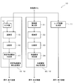
- FIG. 1 is a block diagram showing a configuration of a weather radar apparatus 1 including a shield area detection processing unit 12 (shield area detection apparatus) according to an embodiment of the present invention.
- a shield area detection processing unit 12 shield area detection apparatus
- FIG. 1 is configured to be able to calculate precipitation intensity at each point in a predetermined area.
- the weather radar device 1 includes an antenna 2, a transmission / reception device 3, a signal processing unit 10, and an operation / display device 4 (external device, display device).
- Antenna 2 is a radar antenna that can transmit pulsed radio waves (transmitted waves) with strong directivity.
- the antenna 2 is configured to receive a reflected wave from a target.
- the transmission wave transmitted from the antenna 2 travels in the distance direction (radial direction centered on the antenna 2), while a target (rain, structure, etc. in the present embodiment) is present along the way. In this case, the light is reflected by the target and returned to the antenna 2 as a received wave.
- the weather radar apparatus 1 measures the time from when a pulsed radio wave is transmitted until the reflected wave is received. Thereby, the weather radar apparatus 1 can detect the distance to the target with the weather radar apparatus 1 as a reference.
- the antenna 2 is configured to be able to rotate 360 ° on a horizontal plane and to change the elevation angle ⁇ in the range of 0 ° to 180 °.
- the antenna 2 is configured to repeatedly transmit and receive radio waves at predetermined timings while changing the transmission direction of pulsed radio waves (changing the antenna angle).
- the weather radar device 1 can observe precipitation around the weather radar device 1 over a range of 360 ° on the horizontal plane and an elevation angle of 0 ° to 180 ° (that is, within a hemispherical range). it can.
- the reflected wave received by the antenna 2 is converted into an electric signal and then output to the receiving unit 7.
- the operation from the transmission of a pulsed radio wave to the transmission of the next pulsed radio wave is referred to as “sweep”.
- the operation of moving the antenna in the range of 360 ° on the horizontal plane and the elevation angle of 0 ° to 180 ° while transmitting / receiving radio waves is called “scan”.
- the transmission / reception device 3 includes a transmission / reception switching unit 5, a transmission unit 6, and a reception unit 7.
- the transmission / reception switching unit 5 switches to a connection in which a transmission signal is transmitted from the transmission unit 6 to the antenna 2 at the time of transmission.
- the transmission / reception switching unit 5 switches to a connection in which an electrical signal from the antenna 2 is transmitted to the reception unit 7 at the time of reception.
- the transmission unit 6 outputs a transmission signal generated based on the conditions set in the operation / display device 4 to the antenna 2 via the transmission / reception switching unit 5.
- the transmission unit 6 of the present embodiment outputs a transmission signal that is a basis of a transmission wave transmitted from the antenna 2 to the antenna 2.
- the receiving unit 7 amplifies the electrical signal sent from the antenna 2 and A / D converts the amplified received signal. Thereafter, the receiving unit 7 outputs the received signal converted into the digital signal to the signal processing unit 10.
- the received signal output to the signal processing unit 10 is obtained by correcting the echo intensity according to the distance from the antenna 2.
- the signal processing unit 10 processes the reception signal output from the reception unit 7.
- the signal processing unit 10 includes a radar image generation unit 11 and a shielding area detection processing unit 12.
- the radar image generation unit 11 processes the reception signal output from the reception unit 7 and generates a radar image from the intensity of echoes caused by precipitation at each point in a predetermined hemispherical range centered on the weather radar device 1. .
- the radar image generation unit 11 generates a radar image at every predetermined timing. Radar images generated by the radar image generation unit 11 are sequentially output to the operation / display device 4. As a result, the latest rain radar image is displayed on the operation / display device 4.
- the shielded area detection processing unit 12 performs a process for detecting a shielded area present in an area where precipitation intensity can be observed.
- the shielding area is an area farther than the shielding object, and the transmission wave transmitted from the antenna 2 is shielded by the shielding object so that rain cannot be observed by the transmission wave. Examples of the above-described shield include structures such as buildings, mountains, and rain. The configuration and operation of the shielding area detection processing unit 12 will be described later in detail.
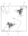
- FIG. 3 is a diagram showing an example of a radar image displayed on the operation / display device 4.
- the precipitation intensity at each point within a predetermined range centering on the weather radar apparatus 1 is represented by a color tone corresponding to the precipitation intensity.
- a point where precipitation intensity per hour is 50 mm or more is represented by red
- a point of 20 mm or more and less than 50 is represented by yellow
- a point of 1 mm or more and less than 20 mm is represented by blue.
- the precipitation intensity is shown corresponding to the dot density.
- the ranges of the shielding areas Zr and Zs detected by the shielding area detection processing unit 12 are displayed.
- the shielding areas Zr and Zs are shown as areas surrounded by broken lines with reference to FIG. The user can recognize the range surrounded by the broken line as the shielding areas Zr and Zs.
- the shielding area detection processing unit 12 performs a process for detecting a shielding area, which is an area in which the precipitation intensity cannot be observed by the transmission wave.
- the shielding area detection processing unit 12 includes a rain shielding area detection processing unit 20 and a fixed object shielding area detection processing unit 13.
- the rain shielding area detection processing unit 20 performs processing for detecting a shielding area due to rain as a shielding object.
- the rain shielding area detection processing unit 20 includes an amplitude value calculation unit 21, an integration unit 22 (comparison target value calculation unit), a comparison unit 23, and a rain shielding area determination unit 24.
- the amplitude value calculation unit 21 calculates the amplitude value of the echo signal output from the reception unit 7 in order from the sample point closer to the weather radar apparatus 1 toward the far side.
- the amplitude value calculation unit 21 performs such calculation processing for each sweep (for each azimuth and for each elevation angle).
- the amplitude value calculation unit 21 sequentially outputs the sequentially calculated amplitude values of the sample points to the integration unit 22.
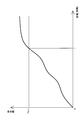
- FIG. 4 is a graph showing the change over time in the integrated value calculated by the integrating unit 22.
- the integrating unit 22 sequentially integrates the amplitude values output from the amplitude value calculating unit 21 and outputs the integrated values to the comparing unit 23 each time.
- the comparing unit 23 sequentially compares the integrated value sequentially output from the integrating unit 22 with the first threshold Thr1.
- the comparison unit 23 outputs the comparison result (whether the integrated value is equal to or less than the first threshold value Thr1 or whether the integrated value exceeds the first threshold value Thr1) to the rain shielding area determination unit 24 each time.
- the rain shielding area determination unit 24 determines the shielding area Zr caused by rain based on the comparison result in the comparison unit 23. Specifically, when the integrated value is equal to or smaller than the first threshold Thr1, the rain shielding area determination unit 24 does not determine the point where the integrated value is calculated as the shielding area Zr. On the other hand, when the integrated value exceeds the first threshold Thr1, the rain shield area determination unit 24 determines the area beyond the point where the integrated value is calculated as the shield area Zr. Referring to FIG. 4, the rain shielding area determination unit 24 is an area where the distance from the weather radar apparatus 1 is up to r because the integrated value at a position closer than the distance r does not exceed the first threshold Thr1. Is not determined as the shielding area Zr. On the other hand, the rain shielding area determination unit 24 determines an area beyond the distance r as the shielding area Zr. The rain shielding area determination unit 24 performs such determination processing in each sweep.
- the fixed object shielding area detection processing unit 13 performs a process for detecting a shielding area Zs (fixed object shielding area) caused by a fixed object (a structure such as a mountain or a building) as a shielding object.
- the fixed object shielding area detection processing unit 13 includes a ground clutter removing unit 14 (described as a GCR unit in FIG. 2), a subtracting unit 15 (fixed object comparison target value calculating unit), a comparing unit 16, and a fixed object shielding area determination. Part 17.
- the ground clutter removing unit 14 is configured to remove clutter (so-called ground clutter) caused by a fixed object provided as a structure such as a mountain or a building from the echo signal output from the receiving unit 7. .
- clutter clutter
- MTI MicrovingMTTargetMTIndicator
- the echo signal from which the ground clutter is removed by the ground clutter removal unit 14 is output to the subtraction unit 15 as a ground clutter removal signal.
- the subtractor 15 subtracts the ground clutter removal signal from the echo signal output from the receiver 7. Since the echo signal is composed of an echo signal caused by rain and a ground clutter, the subtraction result in the subtracting unit 15 corresponds to a ground clutter component (a component caused by a fixed object, a fixed object comparison target value). It will be.
- the subtracting unit 15 performs a process of calculating a difference in echo intensity between sample points corresponding to each other in the echo signal and the ground clutter removal signal from the receiving unit 7.
- the comparison unit 16 compares the subtraction value output from the subtraction unit 15 with the second threshold Thr2.
- the comparison unit 16 outputs the comparison result (whether the subtraction value is equal to or less than the second threshold value Thr2 or the integrated value exceeds the second threshold value Thr2) to the fixed object shielding area determination unit 17 each time.
- the fixed object shielding area determination unit 17 determines the shielding area Zs caused by the fixed object based on the comparison result in the comparison unit 16. Specifically, when the integrated value is equal to or smaller than the second threshold Thr2, the fixed object shielding area determination unit 17 does not determine the point where the subtraction value is calculated as the shielding area. On the other hand, when the subtraction value exceeds the second threshold Thr2, the fixed object occlusion area determination unit 17 determines an area beyond the point where the subtraction value is calculated as an occlusion area.
- the shielding area Zr caused by rain detected by the rain shielding area detection processing unit 20 as described above is displayed on the operation / display device 4 as an area surrounded by a broken line as shown in FIG. As a result, the user can recognize that it is impossible to observe rain in the area Zr. Therefore, there is a possibility that it is raining without uniquely recognizing that it is not raining in the area Zr. Can also be considered.
- the shielding area Zs caused by the fixed object St (see FIG. 3) detected by the fixed object shielding area detection processing unit 13 as described above is operated as an area surrounded by a broken line as shown in FIG. Displayed on the display device 4
- the user can recognize that it is impossible to observe rain in the area Zs. Therefore, the possibility that it is raining without being unambiguously identified as not raining in the area Zs is possible. Can also be considered. 3 is illustrated for convenience and is not displayed on the actual operation / display device 4. In FIG.
- the shielding area detection processing unit 12 of the weather radar apparatus 1 detects the shielding area Zr generated by the shielding object caused by rain. Thereby, since the area
- the comparison target value for determining the shielding area Zr is set to a value corresponding to the distance traveled by the transmission wave (in this embodiment, the integrated value of the echo amplitude value). Since the shielding area Zr is an area where the transmission wave gradually attenuates and does not reach as it travels through the precipitation area, the comparison target value is a value corresponding to the distance traveled by the transmission wave as in this embodiment. Thus, the shielding area Zr can be appropriately determined.
- the shielding area Zr can be appropriately determined.
- the shielding area detection processing unit 12 integrates the amplitude values of the echo signals output from the receiving unit 7 in the order of sample numbers (that is, in order from the sample closer to the weather radar apparatus 1 toward the far side).
- the value is calculated as the comparison target value described above. Thereby, the comparison target value can be easily obtained from the amplitude value of the echo signal output from the receiving unit 7.
- the shielding area detection processing unit 12 determines the area beyond the calculated distance as the shielding area Zr. In this case, it is not necessary to integrate the amplitude values of the echo signals of the samples that are beyond the distance for which the integrated value is calculated, so that the calculation load on the shielding area detection processing unit 12 can be reduced.
- the shielding area detection processing unit 12 detects the shielding area Zs on the far side from the fixed object (mountain, structure, etc.) based on the echo intensity of the ground clutter signal obtained by subtracting the echo signal from the ground clutter removal signal. is doing. Thereby, the shielding area Zs resulting from a fixed object can be determined appropriately.
- the weather radar apparatus 1 outputs information about the shielding areas Zr and Zs to the external device, the shielding areas Zr and Zs are grasped by the external apparatus (in the present embodiment, the operation / display device 4). be able to. Further, in the weather radar device 1, since the shielding areas Zr and Zs are displayed on the operation / display device 4 as an external device, the user can easily visually grasp the positions and sizes of the shielding areas Zr and Zs. can do.
- the weather radar apparatus 1 can constitute a radar apparatus having a shielding area detection processing unit 12 that can detect the shielding areas Zr and Zs appropriately.
- the user views the shielding areas Zr and Zs by viewing the radar image. I can grasp it. And by grasping
- FIG. 5 is a block diagram showing a configuration of a signal processing unit 10a of a weather radar apparatus according to a modification.
- the signal processing unit 10a of this modification is different in the configuration of the rain shielding area detection processing unit 25 from the signal processing unit 10 of the above-described embodiment.
- the rain shielding area detection processing unit 25 includes a precipitation intensity calculating unit 26, an integrating unit 27 (comparison target value calculating unit), a comparing unit 28, and a rain shielding area determining unit 29. .
- the precipitation intensity calculation unit 26 calculates precipitation intensity, which is precipitation per unit time, at each point based on the echo signal output from the reception unit 7.
- the precipitation intensity calculation unit 26 calculates the precipitation intensity at each point using, for example, the Kdp method.
- the precipitation intensity calculation unit 26 performs this calculation process for each sweep (for each azimuth and for each elevation angle).
- the precipitation intensity calculating unit 26 sequentially outputs the precipitation intensity of each sample point calculated sequentially to the integrating unit 27.
- the Kdp method is a technique for calculating precipitation intensity using a differential value of a propagation phase difference between horizontal polarization and vertical polarization.
- strength using Kdp method was given and demonstrated here, it is not restricted to this, You may calculate precipitation intensity using another method (for example, Zh method).
- the accumulating unit 27 sequentially accumulates the precipitation intensity output from the precipitation intensity calculating unit 26 and outputs the accumulated value to the comparing unit 28 each time.
- the comparing unit 28 sequentially compares the integrated value sequentially output from the integrating unit 27 with a threshold value.
- the comparison unit 28 outputs the comparison result to the rain shielding area determination unit 29 each time.
- the rain shielding area determination unit 29 determines a shielding area caused by rain based on the comparison result in the comparison unit 28. Specifically, when the integrated value is equal to or less than the threshold value, the rain shielding area determination unit 29 does not determine the point where the integrated value is calculated as the shielding area. On the other hand, when the integrated value exceeds the threshold value, the rain shielding area determination unit 29 determines an area beyond the point where the integrated value is calculated as the shielding area. The rain shielding area determination unit 29 performs such determination processing for each sweep (for each direction).
- the shielding area detection processing unit 12a of the weather radar apparatus according to the present modification can appropriately determine the shielding area Zr as in the case of the shielding area detection processing unit 12 of the above embodiment.
- the precipitation intensity obtained from the echo signal output from the receiving unit 7 is integrated in the order of sample numbers (that is, in order from the sample closer to the weather radar device 1 toward the far side).
- the integrated value is calculated as the above-described comparison target value.
- the comparison target value can be easily obtained by using a known method such as Kdp method, Zh method, or the like.
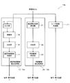
- FIG. 6 is a block diagram showing a configuration of the signal processing unit 10b of the weather radar apparatus according to the modification.
- the signal processing unit 10b of the present modification is different in the configuration of the rain shielding area detection processing unit 30 from the signal processing unit 10 of the above-described embodiment.
- the rain shielding area detection processing unit 30 of the present modification includes an inter-polarization phase difference calculation unit 31 (comparison target value calculation unit), a comparison unit 32, and a rain shielding area determination unit 33.
- the inter-polarization phase difference calculation unit 31 calculates the inter-polarization phase difference ⁇ dp at each point based on the echo signal output from the reception unit 7.
- the inter-polarization phase difference calculation unit 31 performs this calculation process for each sweep (for each direction).
- the inter-polarization phase difference calculation unit 31 sequentially outputs the inter-polarization phase difference ⁇ dp of each sample point sequentially calculated to the comparison unit 32. Since the method for calculating the inter-polarization phase difference ⁇ dp is known, a detailed description thereof will be omitted.
- the comparison unit 32 sequentially compares the inter-polarization phase difference ⁇ dp sequentially output from the inter-polarization phase difference calculation unit 31 with a threshold value.
- the comparison unit 32 outputs the comparison result to the rain shielding area determination unit 33 each time.
- the rain shielding area determination unit 33 determines the shielding area caused by rain based on the comparison result in the comparison unit 32. Specifically, when the inter-polarization phase difference ⁇ dp is equal to or less than the threshold value, the rain shielding area determination unit 33 does not determine the point where the inter-polarization phase difference ⁇ dp is calculated as the shielding area. On the other hand, when the inter-polarization phase difference ⁇ dp exceeds the threshold, the rain shielding area determination unit 33 determines an area beyond the point where the inter-polarization phase difference ⁇ dp is calculated as the shielding area. The rain shielding area determination unit 33 performs such determination processing for each sweep (for each direction).
- the shielding area detection processing unit 12b of the weather radar apparatus according to the present modification can appropriately determine the shielding area Zr as in the case of the shielding area detection processing unit 12 of the above embodiment.
- the shielding area detection processing unit 12b calculates the inter-polarization phase difference ⁇ dp obtained from the echo signal output from the receiving unit 7 as a comparison target value.
- the comparison target value can be easily obtained using the ⁇ dp method known as a known method.
- FIG. 7 is a block diagram showing a configuration of the signal processing unit 10c of the weather radar apparatus according to the modification.
- the shielding area detection processing unit 12 including the fixed object shielding area detection processing unit 13 has been described as an example.
- the present invention is not limited thereto, and as illustrated in FIG. The configuration may be such that the portion 13 is omitted.
Landscapes
- Engineering & Computer Science (AREA)
- Remote Sensing (AREA)
- Radar, Positioning & Navigation (AREA)
- Physics & Mathematics (AREA)
- Environmental & Geological Engineering (AREA)
- General Physics & Mathematics (AREA)
- Computer Networks & Wireless Communication (AREA)
- Atmospheric Sciences (AREA)
- Electromagnetism (AREA)
- Environmental Sciences (AREA)
- Ecology (AREA)
- Biodiversity & Conservation Biology (AREA)
- Life Sciences & Earth Sciences (AREA)
- Radar Systems Or Details Thereof (AREA)
Abstract
【課題】送信波によって降水を観測することができない領域である遮蔽域を適切に判定する。 【解決手段】送波部から送波される送信波が遮蔽される領域である遮蔽域を検出する遮蔽域検出装置12を対象とする。遮蔽域検出装置12は、送信波の反射波に基づくエコー信号から得られる値であって送信波が進んだ距離に応じた比較対象値、を算出する比較対象値算出部22と、比較対象値と閾値とを比較する比較部23と、比較部23での比較結果に基づいて遮蔽域を判定する遮蔽域判定部24と、を備えている。
Description
本発明は、送信波が遮蔽される遮蔽域を検出する遮蔽域検出装置、この遮蔽域検出装置を備えたレーダ装置及び気象レーダ装置、並びに遮蔽域検出方法に関する。
従来より、例えば特許文献1及び2に開示されるような気象レーダ装置が知られている。これらの気象レーダ装置では、アンテナから送波された送信波が雨で反射して帰来する反射波に基づいて、探知範囲の各地点における降水強度を算出している。
ところで、上述した送信波は、降水域を進むにつれて減衰(電波消散)するため、降水域よりも遠い領域であって送信波が十分に届かない領域(以下、遮蔽域と称する)においては、降水を観測することができない。この遮蔽域を適切に判定することは、当該領域に送信波が十分に届いていないことをユーザに通知することによりユーザが当該領域で降水していないと誤認識することを防止する上で、非常に重要である(遮蔽域では、降水している可能性もある)。しかしながら、上述した特許文献1及び2には、遮蔽域の判定については、何ら記載されていない。
本発明は、上記課題を解決するためのものであり、その目的は、送信波によって降水を観測することができない領域である遮蔽域を適切に判定することである。
(1)上記課題を解決するために、この発明のある局面に係る遮蔽域検出装置は、送波部から送波される送信波が遮蔽される領域である遮蔽域を検出する遮蔽域検出装置であって、前記送信波の反射波に基づくエコー信号から得られる値であって、前記送信波が進んだ距離に応じた比較対象値、を算出する比較対象値算出部と、前記比較対象値と閾値とを比較する比較部と、前記比較部での比較結果に基づいて前記遮蔽域を判定する遮蔽域判定部と、を備えている。
(2)好ましくは、前記比較対象値算出部は、前記エコー信号の振幅値を前記送波部側から前記送波部を中心として離れる距離方向に順次積算した値を、前記比較対象値として順次算出する。
(3)好ましくは、前記比較対象値算出部は、前記エコー信号に基づいて算出された降水強度を前記送波部側から前記送波部を中心として離れる距離方向に順次積算した値を、前記比較対象値として順次算出する。
(4)好ましくは、前記送波部は、互いに偏波方向が異なる2つの前記送信波を送波し、前記比較対象値算出部は、2つの前記送信波が降水域で反射して帰来する反射波の偏波間位相差を、前記比較対象値として算出する。
(5)好ましくは、前記遮蔽域判定部は、順次算出された前記比較対象値が前記閾値を超えた場合、該比較対象値が算出された距離以遠の領域を前記遮蔽域として判定する。
(6)好ましくは、前記遮蔽域検出装置は、前記エコー信号からグランドクラッタ成分を除去してグランドクラッタ除去信号を生成するグランドクラッタ除去部と、前記エコー信号から前記グランドクラッタ除去信号を減算した信号としてのグランドクラッタ信号から、そのエコー強度である固定物比較対象値を算出する固定物比較対象値算出部と、前記固定物比較対象値と閾値とを比較する前記比較部と、前記比較部での比較結果に基づいて前記固定物遮蔽域を判定する固定物遮蔽域判定部とを有している。
(7)好ましくは、前記遮蔽域検出装置は、前記遮蔽域判定部によって判定された前記遮蔽域に関する情報を外部装置に出力する。
(8)更に好ましくは、前記遮蔽域検出装置は、前記遮蔽域判定部によって判定された前記遮蔽域に関する情報を前記外部装置としての表示装置に出力し、該表示装置には前記遮蔽域に関する情報が表示される。
(9)上記課題を解決するために、この発明のある局面に係るレーダ装置は、上述したいずれかの遮蔽域検出装置を備えている。
(10)上記課題を解決するために、この発明のある局面に係るレーダ装置としての気象レーダ装置は、気象に関する情報と前記遮蔽域に関する情報とが表示される表示装置を有している。
(11)上記課題を解決するために、この発明のある局面に係る遮蔽域検出方法は、送波部から送波される送信波が遮蔽される領域である遮蔽域を検出する遮蔽域検出方法であって、前記送信波の反射波に基づくエコー信号から得られる値であって、前記送信波が進んだ距離に応じた比較対象値、を算出するステップと、前記比較対象値と閾値とを比較するステップと、前記比較するステップでの比較結果に基づいて前記遮蔽域を判定するステップと、を含む。
また、他の局面に係る遮蔽域検出装置は、送信波が遮蔽される領域である遮蔽域を検出する遮蔽域検出装置であって、前記送信波の反射波に基づくエコー信号からグランドクラッタ成分を除去してグランドクラッタ除去信号を生成するグランドクラッタ除去部と、前記エコー信号から前記グランドクラッタ除去信号を減算してグランドクラッタ信号を生成する減算部と、前記グランドクラッタ信号と閾値とを比較する比較部と、前記比較部での比較結果に基づいて前記遮蔽域を判定する遮蔽域判定部と、を備えている。
本発明によれば、送信波によって降水を観測することができない領域である遮蔽域を適切に判定できる。
図1は、本発明の実施形態に係る遮蔽域検出処理部12(遮蔽域検出装置)を含む気象レーダ装置1の構成を示すブロック図である。以下では、本発明の実施形態に係る気象レーダ装置1について、図を参照して説明する。図1に示す気象レーダ装置1は、所定エリア内の各地点における降水強度を算出可能に構成されている。
[全体構成]
気象レーダ装置1は、図1に示すように、アンテナ2と、送受信装置3と、信号処理部10と、操作・表示装置4(外部装置、表示装置)とを備えている。
気象レーダ装置1は、図1に示すように、アンテナ2と、送受信装置3と、信号処理部10と、操作・表示装置4(外部装置、表示装置)とを備えている。
アンテナ2は、指向性の強いパルス状電波(送信波)を送波可能なレーダアンテナである。また、アンテナ2は、物標からの反射波を受波するように構成されている。アンテナ2から送波された送信波は、距離方向(アンテナ2を中心とした径方向)に向かって進む一方、その途中に物標(本実施形態の場合、雨、構造物等)が存在する場合には当該物標で反射して受信波としてアンテナ2に帰来する。気象レーダ装置1は、パルス状電波を送波してから反射波を受波するまでの時間を測定する。これにより、気象レーダ装置1は、該気象レーダ装置1を基準とした物標までの距離、を検出することができる。アンテナ2は、水平面上で360°回転可能、且つ仰角φを0°~180°の範囲で変更可能に構成されている。アンテナ2は、パルス状電波の送波方向を変えながら(アンテナ角度を変えながら)、電波の送受波を所定のタイミング毎に繰り返し行うように構成されている。以上の構成で、気象レーダ装置1は、気象レーダ装置1周辺の降水の観測を、水平面上の360°及び仰角0°~180°の範囲にわたり(すなわち、半球状の範囲内で)行うことができる。アンテナ2で受波された反射波は、電気信号に変換された後、受信部7に出力される。
なお、以下の説明では、パルス状電波を送波してから次のパルス状電波を送波するまでの動作を「スイープ」という。また、電波の送受信を行いながらアンテナを水平面上の360°及び仰角0°~180°の範囲で動かす動作を「スキャン」と呼ぶ。
送受信装置3は、送受切替部5と、送信部6と、受信部7とを備えている。送受切替部5は、送信時には、送信部6からアンテナ2に送信信号が送られる接続に切り替える。また、送受切替部5は、受信時には、アンテナ2からの電気信号が受信部7に送られる接続に切り替える。
送信部6は、操作・表示装置4において設定された条件に基づいて生成した送信信号を、送受切替部5を介してアンテナ2に対して出力する。本実施形態の送信部6は、アンテナ2から送波される送信波の基となる送信信号をアンテナ2に出力する。
受信部7は、アンテナ2から送られた電気信号を増幅し、増幅した受信信号をA/D変換する。その後、受信部7は、デジタル信号に変換された受信信号を、信号処理部10に対して出力する。なお、信号処理部10に出力される受信信号は、そのエコー強度がアンテナ2からの距離に応じて補正されたものである。
信号処理部10は、受信部7から出力される受信信号を処理する。信号処理部10は、レーダ画像生成部11と、遮蔽域検出処理部12と、を備えている。
レーダ画像生成部11は、受信部7から出力される受信信号を処理し、気象レーダ装置1を中心とした半球状の所定範囲の各地点における降水に起因するエコーの強度からレー
ダ画像を生成する。レーダ画像生成部11は、レーダ画像を、所定のタイミング毎に生成する。レーダ画像生成部11によって生成されたレーダ画像は、順次、操作・表示装置4に出力される。これにより、操作・表示装置4には、最新の雨レーダ画像が表示される。
ダ画像を生成する。レーダ画像生成部11は、レーダ画像を、所定のタイミング毎に生成する。レーダ画像生成部11によって生成されたレーダ画像は、順次、操作・表示装置4に出力される。これにより、操作・表示装置4には、最新の雨レーダ画像が表示される。
遮蔽域検出処理部12は、降水強度の観測可能エリア内に存在する遮蔽域を検出するための処理を行う。遮蔽域とは、遮蔽物よりも遠方の領域であって、アンテナ2から送波された送信波が遮蔽物によって遮蔽されることで送信波による雨の観測ができない領域をいう。上述した遮蔽物としては、ビル等の構造物、山、或いは雨等が挙げられる。遮蔽域検出処理部12の構成及び動作については、詳しくは後述する。
図3は、操作・表示装置4に表示されるレーダ画像の一例を示す図である。操作・表示装置4では、気象レーダ装置1を中心とした所定範囲内の各地点の降水強度が、その降水強度に対応した色調によって表される。具体的には、例えば一例として、1時間あたりの降水強度が50mm以上の地点が赤、20mm以上50未満の地点が黄、1mm以上20mm未満の地点が青、で表される。なお、図3に示す例では、降水強度をドットの濃度に対応させて示している。
また、操作・表示装置4では、遮蔽域検出処理部12によって検出された遮蔽域Zr,Zsの範囲が表示される。具体的には、例えば一例として、遮蔽域Zr,Zsは、図3を参照して、破線によって囲まれた領域として示される。ユーザは、当該破線で囲まれた範囲を、遮蔽域Zr,Zsとして認識できる。
[遮蔽域検出処理部の構成]
遮蔽域検出処理部12は、送信波による降水強度の観測を行うことができない領域である遮蔽域を検出するための処理を行う。遮蔽域検出処理部12は、雨遮蔽域検出処理部20と、固定物遮蔽域検出処理部13と、を備えている。
遮蔽域検出処理部12は、送信波による降水強度の観測を行うことができない領域である遮蔽域を検出するための処理を行う。遮蔽域検出処理部12は、雨遮蔽域検出処理部20と、固定物遮蔽域検出処理部13と、を備えている。
雨遮蔽域検出処理部20は、遮蔽物としての雨による遮蔽域を検出するための処理を行う。雨遮蔽域検出処理部20は、振幅値算出部21と、積算部22(比較対象値算出部)と、比較部23と、雨遮蔽域判定部24と、を有している。
振幅値算出部21は、受信部7から出力されたエコー信号の振幅値を、気象レーダ装置1に近い側のサンプル点から遠い側へ向かって順に、算出する。振幅値算出部21は、このような算出処理を、スイープ毎(方位毎及び仰角毎)に行う。振幅値算出部21は、順次算出した各サンプル点の振幅値を、順次、積算部22に出力する。
図4は、積算部22によって算出される積算値の時間変化を示すグラフである。積算部22は、振幅値算出部21から出力される振幅値を順次積算し、その積算値を都度、比較部23へ出力する。
比較部23は、積算部22から順次出力される積算値を、第1閾値Thr1と順次比較する。比較部23は、その比較結果(積算値が第1閾値Thr1以下か、又は積算値が第1閾値Thr1を超えているか)を都度、雨遮蔽域判定部24へ出力する。
雨遮蔽域判定部24は、比較部23での比較結果に基づき、雨に起因する遮蔽域Zrを判定する。具体的には、雨遮蔽域判定部24は、積算値が第1閾値Thr1以下の場合、その積算値が算出された地点を、遮蔽域Zrと判定しない。一方、雨遮蔽域判定部24は、その積算値が第1閾値Thr1を超えた場合、その積算値が算出された地点以遠の領域を、遮蔽域Zrとして判定する。図4を参照して説明すると、雨遮蔽域判定部24は、距離rよりも近い位置での積算値は第1閾値Thr1を超えていないため、気象レーダ装置
1からの距離がrまでの領域については、遮蔽域Zrと判定しない。一方、雨遮蔽域判定部24は、距離r以遠の領域を遮蔽域Zrと判定する。雨遮蔽域判定部24は、このような判定処理を、各スイープにおいて行う。
1からの距離がrまでの領域については、遮蔽域Zrと判定しない。一方、雨遮蔽域判定部24は、距離r以遠の領域を遮蔽域Zrと判定する。雨遮蔽域判定部24は、このような判定処理を、各スイープにおいて行う。
固定物遮蔽域検出処理部13は、遮蔽物としての固定物(山、ビル等の構造物等)に起因する遮蔽域Zs(固定物遮蔽域)を検出するための処理を行う。固定物遮蔽域検出処理部13は、グランドクラッタ除去部14(図2ではGCR部と記載)と、減算部15(固定物比較対象値算出部)と、比較部16と、固定物遮蔽域判定部17と、を有している。
グランドクラッタ除去部14は、受信部7から出力されるエコー信号のうち、山、ビル等の構造物等として設けられる固定物に起因するクラッタ(いわゆるグランドクラッタ)を除去するように構成されている。グランドクラッタ除去部14には、例えば、MTI(Moving Target Indicator)フィルタ、或いはハイパスフィルタ等が用いられる。グランドクラッタ除去部14によってグランドクラッタが除去されたエコー信号は、グランドクラッタ除去信号として、減算部15に出力される。
減算部15は、受信部7から出力されるエコー信号からグランドクラッタ除去信号を減算する。エコー信号は、雨に起因するエコー信号とグランドクラッタとで構成されているため、減算部15での減算結果は、グランドクラッタ成分(固定物に起因する成分、固定物比較対象値)に相当することになる。減算部15は、受信部7からのエコー信号及びグランドクラッタ除去信号において、距離的に対応するサンプル点同士のエコー強度の差を算出する処理を行う。
比較部16は、減算部15から出力された減算値を第2閾値Thr2と比較する。比較部16は、その比較結果(減算値が第2閾値Thr2以下か、又は積算値が第2閾値Thr2を超えているか)を都度、固定物遮蔽域判定部17へ出力する。
固定物遮蔽域判定部17は、比較部16での比較結果に基づき、固定物に起因する遮蔽域Zsを判定する。具体的には、固定物遮蔽域判定部17は、積算値が第2閾値Thr2以下の場合、その減算値が算出された地点を、遮蔽域と判定しない。一方、固定物遮蔽域判定部17は、その減算値が第2閾値Thr2を超えた場合、その減算値が算出された地点以遠の領域を、遮蔽域として判定する。
上述のようにして雨遮蔽域検出処理部20によって検出された雨に起因する遮蔽域Zrは、図3に示すように、破線で囲まれた領域として操作・表示装置4に表示される。これにより、ユーザは、当該領域Zrでは降雨の観測が不可能であることを認識できるため、当該領域Zrで雨が降っていないと一義的に誤認識することなく、雨が降っている可能性についても考慮することができる。
また、上述のようにして固定物遮蔽域検出処理部13によって検出された固定物St(図3参照)に起因する遮蔽域Zsは、図3に示すように、破線で囲まれた領域として操作・表示装置4に表示される。これにより、ユーザは、当該領域Zsでは降雨の観測が不可能であることを認識できるため、当該領域Zsで雨が降っていないと一義的に誤認識することなく、雨が降っている可能性についても考慮することができる。なお、図3で図示する固定物Stを示す一点鎖線は、便宜上図示したものであり、実際の操作・表示装置4では表示されない。
[効果]
以上のように、本実施形態に係る気象レーダ装置1の遮蔽域検出処理部12では、雨に起因する遮蔽物によって生成される遮蔽域Zrが検出される。これにより、気象レーダ装
置1によって降水を観測することができない領域を把握することができるため、ユーザが一義的に、当該領域Zrにおいて降水が観測されていないと判断してしまうことを防止できる。
以上のように、本実施形態に係る気象レーダ装置1の遮蔽域検出処理部12では、雨に起因する遮蔽物によって生成される遮蔽域Zrが検出される。これにより、気象レーダ装
置1によって降水を観測することができない領域を把握することができるため、ユーザが一義的に、当該領域Zrにおいて降水が観測されていないと判断してしまうことを防止できる。
また、遮蔽域検出処理部12では、遮蔽域Zrを判定するための比較対象値を、送信波が進んだ距離に応じた値(本実施形態の場合、エコー振幅値の積算値)としている。遮蔽域Zrは、送信波が降水域を進むことにより徐々に減衰して届かなくなる領域であるため、本実施形態のように、比較対象値を、送信波が進んだ距離に応じた値とすることで、遮蔽域Zrを適切に判定することができる。
従って、遮蔽域検出処理部12によれば、遮蔽域Zrを適切に判定することができる。
また、遮蔽域検出処理部12では、受信部7から出力されたエコー信号の振幅値を、サンプル番号順に(すなわち、気象レーダ装置1に近い側のサンプルから遠い側に向かって順に)積算した積算値を、上述した比較対象値として算出している。これにより、比較対象値を、受信部7から出力されたエコー信号の振幅値によって容易に求めることができる。
また、遮蔽域検出処理部12では、順次算出された積算値が第1閾値Thr1を超えた場合、その積算値が算出された距離以遠の領域を遮蔽域Zrとして判定している。こうすると、該積算値が算出された距離以遠のサンプルのエコー信号の振幅値を積算する必要がなくなるため、遮蔽域検出処理部12にかかる演算負荷を軽減することができる。
また、遮蔽域検出処理部12では、エコー信号をグランドクラッタ除去信号で減算したグランドクラッタ信号のエコー強度に基づいて、固定物(山、構造物等)よりも遠い側にある遮蔽域Zsを検出している。これにより、固定物に起因する遮蔽域Zsを適切に判定することができる。
また、気象レーダ装置1では、遮蔽域Zr,Zsに関する情報が外部装置に出力されるため、当該外部装置(本実施形態の場合、操作・表示装置4)によって前記遮蔽域Zr,Zsを把握することができる。また、気象レーダ装置1では、外部装置としての操作・表示装置4に遮蔽域Zr,Zsが表示されるため、ユーザは、視覚的に容易に遮蔽域Zr,Zsの位置、大きさ等を把握することができる。
また、気象レーダ装置1では、適切に遮蔽域Zr,Zsを検出可能な遮蔽域検出処理部12を有するレーダ装置を構成することができる。
また、気象レーダ装置1では、検出された遮蔽域Zr,Zsが気象に関する情報としてのレーダ画像上に重ねて表示されるため、ユーザは、当該レーダ画像を見ることにより、遮蔽域Zr,Zsを把握することができる。そして、このように遮蔽域Zr,Zsを把握することにより、ユーザは、当該領域Zr,Zsに雨が観測されない原因が、送信波が当該領域Zr,Zsに十分に届いていないことであると理解でき、当該領域Zr,Zsにおいて降水している可能性についても考慮することができる。
[変形例]
以上、本発明の実施形態について説明したが、本発明はこれらに限定されるものではなく、本発明の趣旨を逸脱しない限りにおいて種々の変更が可能である。
以上、本発明の実施形態について説明したが、本発明はこれらに限定されるものではなく、本発明の趣旨を逸脱しない限りにおいて種々の変更が可能である。
(1)図5は、変形例に係る気象レーダ装置の信号処理部10aの構成を示すブロック図である。本変形例の信号処理部10aは、上述した実施形態の信号処理部10と比べて
、雨遮蔽域検出処理部25の構成が異なっている。
、雨遮蔽域検出処理部25の構成が異なっている。
本変形例の雨遮蔽域検出処理部25は、降水強度算出部26と、積算部27(比較対象値算出部)と、比較部28と、雨遮蔽域判定部29と、を有している。
降水強度算出部26は、受信部7から出力されたエコー信号に基づき、各地点における単位時間当たりの降水量である降水強度を算出する。降水強度算出部26は、例えば、Kdp法等を用いて、各地点の降水強度を算出する。降水強度算出部26は、この算出処理を、スイープ毎(方位毎及び仰角毎)に行う。降水強度算出部26は、順次算出した各サンプル点の降水強度を、順次、積算部27に出力する。
ここで、Kdp法とは、水平偏波及び垂直偏波の伝搬位相差の微分値を用いて降水強度を算出する手法である。なおここでは、Kdp法を用いて降水強度を算出する例を挙げて説明したが、これに限らず、その他の手法(例えばZh法)を用いて降水強度を算出してもよい。
積算部27は、降水強度算出部26から出力される降水強度を順次積算し、その積算値を都度、比較部28へ出力する。
比較部28は、積算部27から順次出力される積算値を閾値と順次比較する。比較部28は、その比較結果を都度、雨遮蔽域判定部29へ出力する。
雨遮蔽域判定部29は、比較部28での比較結果に基づき、雨に起因する遮蔽域を判定する。具体的には、雨遮蔽域判定部29は、積算値が閾値以下の場合、その積算値が算出された地点を、遮蔽域と判定しない。一方、雨遮蔽域判定部29は、積算値が閾値を超えた場合、その積算値が算出された地点以遠の領域を、遮蔽域として判定する。雨遮蔽域判定部29は、このような判定処理を、スイープ毎(方位毎)に行う。
以上のように、本変形例に係る気象レーダ装置の遮蔽域検出処理部12aでも、上記実施形態の遮蔽域検出処理部12の場合と同様、遮蔽域Zrを適切に判定することができる。
また、遮蔽域検出処理部12aでは、受信部7から出力されたエコー信号から得られる降水強度を、サンプル番号順に(すなわち、気象レーダ装置1に近い側のサンプルから遠い側に向かって順に)積算した積算値を、上述した比較対象値として算出している。これにより、比較対象値を、既知の手法として知られているKdp法、Zh法等を用いて容易に求めることができる。
(2)図6は、変形例に係る気象レーダ装置の信号処理部10bの構成を示すブロック図である。本変形例の信号処理部10bは、上述した実施形態の信号処理部10と比べて、雨遮蔽域検出処理部30の構成が異なっている。
本変形例の雨遮蔽域検出処理部30は、偏波間位相差算出部31(比較対象値算出部)と、比較部32と、雨遮蔽域判定部33と、を有している。
偏波間位相差算出部31は、受信部7から出力されたエコー信号に基づき、各地点における偏波間位相差φdpを算出する。偏波間位相差算出部31は、この算出処理を、スイープ毎(方位毎)に行う。偏波間位相差算出部31は、順次算出した各サンプル点の偏波間位相差φdpを、順次、比較部32に出力する。なお、偏波間位相差φdpの算出手法は公知であるため、その詳細な説明を省略する。
比較部32は、偏波間位相差算出部31から順次出力される偏波間位相差φdpを閾値と順次比較する。比較部32は、その比較結果を都度、雨遮蔽域判定部33へ出力する。
雨遮蔽域判定部33は、比較部32での比較結果に基づき、雨に起因する遮蔽域を判定する。具体的には、雨遮蔽域判定部33は、偏波間位相差φdpが閾値以下の場合、その偏波間位相差φdpが算出された地点を、遮蔽域と判定しない。一方、雨遮蔽域判定部33は、偏波間位相差φdpが閾値を超えた場合、その偏波間位相差φdpが算出された地点以遠の領域を、遮蔽域として判定する。雨遮蔽域判定部33は、このような判定処理を、スイープ毎(方位毎)に行う。
以上のように、本変形例に係る気象レーダ装置の遮蔽域検出処理部12bでも、上記実施形態の遮蔽域検出処理部12の場合と同様、遮蔽域Zrを適切に判定することができる。
また、遮蔽域検出処理部12bでは、受信部7から出力されたエコー信号から得られる偏波間位相差φdpを、比較対象値として算出している。これにより、比較対象値を、既知の手法として知られているφdp法を用いて容易に求めることができる。
(3)図7は、変形例に係る気象レーダ装置の信号処理部10cの構成を示すブロック図である。上述した実施形態では、固定物遮蔽域検出処理部13を備えた遮蔽域検出処理部12を例に挙げて説明したが、これに限らず、図7に示すように、固定物遮蔽域検出処理部13が省略された構成であってもよい。
1 気象レーダ装置(レーダ装置)
2 アンテナ(送波部)
12,12a,12b 遮蔽域検出処理部(遮蔽域検出装置)
22,27 積算部(比較対象値算出部)
23,28,32 比較部
24,29,33 雨遮蔽域判定部(遮蔽域判定部)
31 偏波間位相差算出部(比較対象値算出部)
2 アンテナ(送波部)
12,12a,12b 遮蔽域検出処理部(遮蔽域検出装置)
22,27 積算部(比較対象値算出部)
23,28,32 比較部
24,29,33 雨遮蔽域判定部(遮蔽域判定部)
31 偏波間位相差算出部(比較対象値算出部)
Claims (11)
- 送波部から送波される送信波が遮蔽される領域である遮蔽域を検出する遮蔽域検出装置であって、
前記送信波の反射波に基づくエコー信号から得られる値であって、前記送信波が進んだ距離に応じた比較対象値、を算出する比較対象値算出部と、
前記比較対象値と閾値とを比較する比較部と、
前記比較部での比較結果に基づいて前記遮蔽域を判定する遮蔽域判定部と、
を備えていることを特徴とする、遮蔽域検出装置。 - 請求項1に記載の遮蔽域検出装置において、
前記比較対象値算出部は、前記エコー信号の振幅値を前記送波部側から前記送波部を中心として離れる距離方向に順次積算した値を、前記比較対象値として順次算出することを特徴とする、遮蔽域検出装置。 - 請求項1に記載の遮蔽域検出装置において、
前記比較対象値算出部は、前記エコー信号に基づいて算出された降水強度を前記送波部側から前記送波部を中心として離れる距離方向に順次積算した値を、前記比較対象値として順次算出することを特徴とする、遮蔽域検出装置。 - 請求項1に記載の遮蔽域検出装置において、
前記送波部は、互いに偏波方向が異なる2つの前記送信波を送波し、
前記比較対象値算出部は、2つの前記送信波が降水域で反射して帰来する反射波の偏波間位相差を、前記比較対象値として算出することを特徴とする、遮蔽域検出装置。 - 請求項2から請求項4のいずれか1項に記載の遮蔽域検出装置において、
前記遮蔽域判定部は、順次算出された前記比較対象値が前記閾値を超えた場合、該比較対象値が算出された距離以遠の領域を前記遮蔽域として判定することを特徴とする、遮蔽域検出装置。 - 請求項1から請求項5のいずれか1項に記載の遮蔽域検出装置において、
前記エコー信号からグランドクラッタ成分を除去してグランドクラッタ除去信号を生成するグランドクラッタ除去部と、
前記エコー信号から前記グランドクラッタ除去信号を減算した信号としてのグランドクラッタ信号から、そのエコー強度である固定物比較対象値を算出する固定物比較対象値算出部と、
前記固定物比較対象値と閾値とを比較する前記比較部と、
前記比較部での比較結果に基づいて前記固定物遮蔽域を判定する固定物遮蔽域判定部と
を有していることを特徴とする、遮蔽域検出装置。 - 請求項1から請求項6のいずれか1項に記載の遮蔽域検出装置において、
前記遮蔽域判定部によって判定された前記遮蔽域に関する情報を外部装置に出力することを特徴とする、遮蔽域検出装置。 - 請求項7に記載の遮蔽域検出装置において、
前記遮蔽域判定部によって判定された前記遮蔽域に関する情報を前記外部装置としての表示装置に出力し、該表示装置には前記遮蔽域に関する情報が表示されることを特徴とする、遮蔽域検出装置。 - 請求項1から請求項8のいずれか1項に記載の遮蔽域検出装置を備えた、レーダ装置。
- 気象に関する情報と前記遮蔽域に関する情報とが表示される表示装置を有する、請求項9に記載のレーダ装置としての気象レーダ装置。
- 送波部から送波される送信波が遮蔽される領域である遮蔽域を検出する遮蔽域検出方法であって、
前記送信波の反射波に基づくエコー信号から得られる値であって、前記送信波が進んだ距離に応じた比較対象値、を算出するステップと、
前記比較対象値と閾値とを比較するステップと、
前記比較するステップでの比較結果に基づいて前記遮蔽域を判定するステップと、
を含むことを特徴とする、遮蔽域検出方法。
Applications Claiming Priority (2)
| Application Number | Priority Date | Filing Date | Title |
|---|---|---|---|
| JP2015098967 | 2015-05-14 | ||
| JP2015-098967 | 2015-05-14 |
Publications (1)
| Publication Number | Publication Date |
|---|---|
| WO2016181694A1 true WO2016181694A1 (ja) | 2016-11-17 |
Family
ID=57248061
Family Applications (1)
| Application Number | Title | Priority Date | Filing Date |
|---|---|---|---|
| PCT/JP2016/057287 Ceased WO2016181694A1 (ja) | 2015-05-14 | 2016-03-09 | 遮蔽域検出装置、レーダ装置、気象レーダ装置、及び遮蔽域検出方法 |
Country Status (1)
| Country | Link |
|---|---|
| WO (1) | WO2016181694A1 (ja) |
Cited By (1)
| Publication number | Priority date | Publication date | Assignee | Title |
|---|---|---|---|---|
| JPWO2022244388A1 (ja) * | 2021-05-18 | 2022-11-24 |
Citations (5)
| Publication number | Priority date | Publication date | Assignee | Title |
|---|---|---|---|---|
| JPH0712920A (ja) * | 1993-06-25 | 1995-01-17 | Fujitsu Ltd | レーダ表示装置 |
| JPH11211822A (ja) * | 1998-01-20 | 1999-08-06 | Mitsubishi Electric Corp | レーダ装置 |
| JP2009008440A (ja) * | 2007-06-26 | 2009-01-15 | Mitsubishi Electric Corp | 気象レーダ装置 |
| JP2009098001A (ja) * | 2007-10-17 | 2009-05-07 | National Research Institute For Earth Science & Disaster Provention | 降雨減衰判定装置及びそれを用いた降雨観測システム並びに降雨減衰判定方法 |
| US20140266856A1 (en) * | 2013-03-15 | 2014-09-18 | Lapoint-Blase Industries, Inc. | System and method for filling gaps in radar coverage |
-
2016
- 2016-03-09 WO PCT/JP2016/057287 patent/WO2016181694A1/ja not_active Ceased
Patent Citations (5)
| Publication number | Priority date | Publication date | Assignee | Title |
|---|---|---|---|---|
| JPH0712920A (ja) * | 1993-06-25 | 1995-01-17 | Fujitsu Ltd | レーダ表示装置 |
| JPH11211822A (ja) * | 1998-01-20 | 1999-08-06 | Mitsubishi Electric Corp | レーダ装置 |
| JP2009008440A (ja) * | 2007-06-26 | 2009-01-15 | Mitsubishi Electric Corp | 気象レーダ装置 |
| JP2009098001A (ja) * | 2007-10-17 | 2009-05-07 | National Research Institute For Earth Science & Disaster Provention | 降雨減衰判定装置及びそれを用いた降雨観測システム並びに降雨減衰判定方法 |
| US20140266856A1 (en) * | 2013-03-15 | 2014-09-18 | Lapoint-Blase Industries, Inc. | System and method for filling gaps in radar coverage |
Cited By (3)
| Publication number | Priority date | Publication date | Assignee | Title |
|---|---|---|---|---|
| JPWO2022244388A1 (ja) * | 2021-05-18 | 2022-11-24 | ||
| WO2022244388A1 (ja) * | 2021-05-18 | 2022-11-24 | 古野電気株式会社 | 気象観測装置、気象観測システム、および、気象観測方法 |
| JP7828340B2 (ja) | 2021-05-18 | 2026-03-11 | 古野電気株式会社 | 気象観測装置、気象観測システム、および、気象観測方法 |
Similar Documents
| Publication | Publication Date | Title |
|---|---|---|
| US8207889B2 (en) | Dual polarization radar apparatus and interference judgment method | |
| US8368582B2 (en) | Doppler radar apparatus and method of calculating doppler velocity | |
| JP5284230B2 (ja) | 気象レーダシステムとその信号処理方法 | |
| JP2011095215A (ja) | 信号処理装置、レーダ装置、信号処理プログラム及び信号処理方法 | |
| CN108490426A (zh) | 一种目标测距方法及其设备 | |
| JP5628590B2 (ja) | 干渉除去装置、信号処理装置、レーダ装置、干渉除去方法およびプログラム | |
| KR102387059B1 (ko) | 기상 레이더를 위한 노이즈 제거 장치 및 방법 | |
| JP6278732B2 (ja) | 海洋レーダ装置 | |
| JP5996259B2 (ja) | 津波検出装置、津波検出方法及び津波検出プログラム | |
| EP3006956B1 (en) | Surface tidal-current estimation device, radar device, surface tidal-current estimation method and surface tidal-current estimation program | |
| CN108885257A (zh) | 信号处理装置以及雷达装置 | |
| JP6827577B2 (ja) | 信号処理装置及び信号処理方法 | |
| WO2016181694A1 (ja) | 遮蔽域検出装置、レーダ装置、気象レーダ装置、及び遮蔽域検出方法 | |
| JP6586462B2 (ja) | 水蒸気観測装置 | |
| JP2013160548A (ja) | 二重偏波レーダ装置および偏波間位相差補正方法 | |
| JP5398424B2 (ja) | 気象レーダシステムとその降水強度算出方法及びプログラム | |
| JP5196959B2 (ja) | レーダ装置 | |
| US10480932B2 (en) | Automated computation of a dimension of a moving platform | |
| JP5491788B2 (ja) | 気象レーダシステムとその降水強度算出方法 | |
| JP6132576B2 (ja) | 信号処理装置、レーダ装置、及び信号処理方法 | |
| JP6448179B2 (ja) | レーダ装置 | |
| CN114286946B (zh) | 固态雷达装置、固态雷达控制方法及固态雷达控制程序产品 | |
| JP6138430B2 (ja) | 危険物標検出装置 | |
| JP2009264990A (ja) | レーダ装置 | |
| JP2017181098A (ja) | 物体検知装置 |
Legal Events
| Date | Code | Title | Description |
|---|---|---|---|
| 121 | Ep: the epo has been informed by wipo that ep was designated in this application |
Ref document number: 16792419 Country of ref document: EP Kind code of ref document: A1 |
|
| NENP | Non-entry into the national phase |
Ref country code: DE |
|
| NENP | Non-entry into the national phase |
Ref country code: JP |
|
| 122 | Ep: pct application non-entry in european phase |
Ref document number: 16792419 Country of ref document: EP Kind code of ref document: A1 |