WO2016181582A1 - 電子機器および電子機器の製造方法 - Google Patents
電子機器および電子機器の製造方法 Download PDFInfo
- Publication number
- WO2016181582A1 WO2016181582A1 PCT/JP2015/085978 JP2015085978W WO2016181582A1 WO 2016181582 A1 WO2016181582 A1 WO 2016181582A1 JP 2015085978 W JP2015085978 W JP 2015085978W WO 2016181582 A1 WO2016181582 A1 WO 2016181582A1
- Authority
- WO
- WIPO (PCT)
- Prior art keywords
- cable
- main body
- movable
- housing
- casing
- Prior art date
- Legal status (The legal status is an assumption and is not a legal conclusion. Google has not performed a legal analysis and makes no representation as to the accuracy of the status listed.)
- Ceased
Links
Images




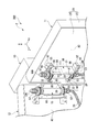
Classifications
-
- H—ELECTRICITY
- H04—ELECTRIC COMMUNICATION TECHNIQUE
- H04B—TRANSMISSION
- H04B1/00—Details of transmission systems, not covered by a single one of groups H04B3/00 - H04B13/00; Details of transmission systems not characterised by the medium used for transmission
- H04B1/38—Transceivers, i.e. devices in which transmitter and receiver form a structural unit and in which at least one part is used for functions of transmitting and receiving
- H04B1/3827—Portable transceivers
- H04B1/3833—Hand-held transceivers
-
- H—ELECTRICITY
- H01—ELECTRIC ELEMENTS
- H01Q—ANTENNAS, i.e. RADIO AERIALS
- H01Q1/00—Details of, or arrangements associated with, antennas
- H01Q1/12—Supports; Mounting means
- H01Q1/1235—Collapsible supports; Means for erecting a rigid antenna
-
- H—ELECTRICITY
- H01—ELECTRIC ELEMENTS
- H01Q—ANTENNAS, i.e. RADIO AERIALS
- H01Q1/00—Details of, or arrangements associated with, antennas
- H01Q1/12—Supports; Mounting means
- H01Q1/22—Supports; Mounting means by structural association with other equipment or articles
- H01Q1/24—Supports; Mounting means by structural association with other equipment or articles with receiving set
- H01Q1/241—Supports; Mounting means by structural association with other equipment or articles with receiving set used in mobile communications, e.g. GSM
- H01Q1/242—Supports; Mounting means by structural association with other equipment or articles with receiving set used in mobile communications, e.g. GSM specially adapted for hand-held use
- H01Q1/243—Supports; Mounting means by structural association with other equipment or articles with receiving set used in mobile communications, e.g. GSM specially adapted for hand-held use with built-in antennas
-
- H—ELECTRICITY
- H04—ELECTRIC COMMUNICATION TECHNIQUE
- H04B—TRANSMISSION
- H04B1/00—Details of transmission systems, not covered by a single one of groups H04B3/00 - H04B13/00; Details of transmission systems not characterised by the medium used for transmission
- H04B1/38—Transceivers, i.e. devices in which transmitter and receiver form a structural unit and in which at least one part is used for functions of transmitting and receiving
- H04B2001/3894—Waterproofing of transmission device
Definitions
- Embodiments described herein relate generally to an electronic device and a method for manufacturing the electronic device.
- a foldable mobile phone having a waterproof hinge structure is known.
- a flexible printed circuit board is passed through a hinge portion that connects two housings.
- the structure of a hinge part tends to become complicated. For this reason, the periphery of the hinge portion is likely to be less waterproof than the other portions.
- the problem to be solved by the present invention is to provide an electronic device and a method for manufacturing the electronic device that can improve waterproofness.
- the electronic device of the embodiment has a movable housing, a main body housing, a connecting portion, a cable, and a seal structure.
- the movable casing has a first opening and includes at least an antenna element.
- the main body housing has a second opening.
- the connection portion includes a connection portion and a fixing portion.
- the connecting portion is connected to the movable casing and communicates with the inside of the movable casing through the first opening.
- the fixing portion is connected to the main body casing and communicates with the inside of the main body casing through the second opening.
- the connection portion rotatably connects the movable housing and the main body housing.
- the cable is electrically connected to the antenna element and extends from the inside of the movable housing through the inside of the connecting portion and the inside of the fixed portion to the inside of the main body housing.
- the seal structure seals between the movable housing and the connection portion and between the main body housing and the fixed portion.
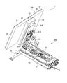
- FIG. 1 is a perspective view illustrating an entire electronic apparatus according to one embodiment.
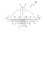
- the side view which shows typically the antenna part shown in FIG.
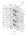
- the perspective view which shows the inside of the antenna part shown in FIG.
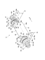
- the perspective view which expands and shows the inside of the 1st movable housing
- FIG. 8 is a cross-sectional view of the antenna portion shown in FIG. 7 taken along line F8-F8.
- FIG. 1 shows an example of the overall configuration of the electronic device 1.
- the electronic apparatus 1 of this embodiment is a planar antenna device.
- the electronic device 1 has an antenna element to be described later, and receives radio waves from a communication satellite and transmits radio waves toward the communication satellite.
- the electronic device 1 is a device that constitutes a part of a VSAT (Very Small Aperture Terminal) system.
- VSAT Very Small Aperture Terminal
- the electronic device 1 of the present embodiment is a foldable planar antenna device designed to be portable by hand.
- the electronic device 1 can be carried and stored in a folded state.
- the electronic device 1 can communicate with a communication satellite in a deployed state.
- the electronic apparatus 1 includes an antenna support structure 201 and an antenna unit 202.
- the antenna support structure 201 includes a first support 211, a second support 212, a third support 213, and a fourth support 214.
- the first support 211 is placed on the installation surface of the installation location.
- the first support 211 is formed in a flat box shape.
- the 2nd support body 212 is connected with the 1st support body 211 so that rotation is possible.
- the second support 212 is rotatable with respect to the first support 211 about a first axis C ⁇ b> 1 extending in the thickness direction of the first support 211.
- the third support 213 is disposed substantially parallel to the antenna unit 202.
- the third support 213 is formed in a flat shape.
- the third support 213 is rotatably connected to the end of the second support 212.
- the third support 213 is rotatable with respect to the second support 212 about a second axis C ⁇ b> 2 that is substantially parallel to the main surface of the first support 211.
- the fourth support 214 is attached to the antenna unit 202. Further, the fourth support 214 is connected to the third support 213 so as to be rotatable.
- the fourth support 214 is rotatable with respect to the third support 213 about a third axis C3 extending in the thickness direction of the third support 213.
- the antenna unit 202 includes a closed position where the antenna unit 202 overlaps the first support 211, and an upright position where the antenna unit 202 is raised from the first support 211.
- the posture can be changed between. Further, the antenna unit 202 can face in a desired direction with respect to the first support body 211.
- FIG. 2 schematically shows the configuration of the antenna unit 202.
- the antenna unit 202 has a foldable casing structure 2 having three casings.
- the housing structure 2 includes a first movable housing 11, a second movable housing 12, a main body housing 13, a first hinge 14, a second hinge 15, and a seal structure 19 (see FIG. 3).
- Each of the first movable casing 11 and the second movable casing 12 is an example of a “movable casing”.
- Each of the first hinge 14 and the second hinge 15 is an example of a “connecting portion”.
- the seal structure 19 includes a movable housing seal portion 53, a cable seal portion 57, and a main body housing seal portion 66, which will be described later.
- the first movable casing 11 is formed in a flat box shape.
- the first movable housing 11 has a first end portion 11a and a second end portion 11b.
- the first end portion 11 a faces the main body housing 13.
- a first hinge 14 is provided between the first end 11 a of the first movable housing 11 and the main body housing 13.
- the 1st hinge 14 has connected the 1st end part 11a of the 1st movable housing
- the second movable casing 12 has substantially the same outer shape as the first movable casing 11. That is, the second movable housing 12 is formed in a flat box shape.
- the second movable housing 12 has a first end 12a and a second end 12b.
- the first end 12 a faces the main body housing 13.
- a second hinge 15 is provided between the first end 12 a of the second movable housing 12 and the main body housing 13.
- the 2nd hinge 15 has connected the 1st end part 12a of the 2nd movable housing
- the first movable housing 11 and the second movable housing 12 are opened to each other by the first hinge 14 and the second hinge 15 (see a solid line in FIG. 2) and closed to face each other (in FIG. 2). 2).
- the first movable casing 11 and the second movable casing 12 are opened approximately 180 degrees from each other.
- the closed state the first movable casing 11 and the second movable casing 12 are folded so as to overlap each other.
- the main body housing 13 is formed in a flat box shape. However, the main body housing 13 is smaller than the first movable housing 11 and the second movable housing 12. For example, the main body housing 13 is disposed so as to be substantially parallel to the first movable housing 11 and the second movable housing 12 in the opened state.
- FIG. 3 shows the inside of the antenna unit 202.
- the first movable housing 11 accommodates a plurality (for example, two) of first antenna substrates 16 as an example of the first antenna component.
- Each first antenna substrate 16 has a plurality of antenna elements 16a.
- the antenna element 16a is a conductor pattern provided on the surface of the first antenna substrate 16, for example.
- the plurality of antenna elements 16a include a first antenna element 16aa and a second antenna element 16ab.
- the first antenna element 16aa and the second antenna element 16ab are distinguished for convenience of description, and the structure and function may be the same.
- the first antenna element 16aa and the second antenna element 16ab may be provided separately on different antenna substrates 16.
- the first antenna substrate 16 is an example of a “first electronic component”.
- the second movable housing 12 accommodates a plurality of (for example, two) second antenna substrates 17 as an example of the second antenna component.
- Each second antenna substrate 17 has a plurality of antenna elements 17a.
- the antenna element 17a is a conductor pattern provided on the surface of the second antenna substrate 17, for example.
- the plurality of antenna elements 17a include a first antenna element 17aa and a second antenna element 17ab.
- the first antenna element 17aa and the second antenna element 17ab are distinguished for convenience of explanation, and the structure and function may be the same.
- the first antenna element 17aa and the second antenna element 17ab may be provided separately on different antenna substrates 17.
- the second antenna substrate 17 is an example of a “second electronic component”.
- the first antenna substrate 16 and the second antenna substrate 17 are components that form a reflecting mirror of a planar antenna.
- the main body casing 13 accommodates a control board 18 (see FIG. 2) as an example of a circuit board.
- the control board 18 is a circuit board including a CPU (Central Processing Unit), for example.
- the control board 18 includes an antenna circuit unit that controls the first antenna board 16 and the second antenna board 17.
- the first movable housing 11 includes a base 21 formed in a bowl shape and a cover 22 attached to the base 21.
- the second movable housing 12 includes a base 21 formed in a bowl shape and a cover 22 attached to the base 21.
- Each cover 22 forms a radome with respect to the first antenna substrate 16 or the second antenna substrate 17.
- the cover 22 and the base 21 are liquid-tightly sealed by a seal member (not shown).
- the main body housing 13 includes a base 21 formed in a bowl shape and a cover 22 attached to the base 21. A space between the base 21 and the cover 22 of the main body housing 13 is liquid-tightly sealed by a seal member (not shown).
- the antenna unit 202 includes a plurality of cables 23 extending inside the first movable casing 11 and a plurality of cables 24 extending inside the second movable casing 12.
- Each of the cable 23 and the cable 24 is a relatively thick cable having a round cross section.
- FIG. 4 is an exploded perspective view showing a part of the antenna unit 202.
- the cable 23 extends from the inside of the first movable housing 11 to the inside of the main body housing 13 through the inside of the first hinge 14.
- the cable 23 electrically connects the first antenna board 16 and the control board 18. That is, the cable 23 electrically connects the antenna element 16 a and the control board 18.
- the cable 24 extends from the inside of the second movable housing 12 to the inside of the main body housing 13 through the inside of the second hinge 15.
- the cable 24 electrically connects the second antenna board 17 and the control board 18. That is, the cable 24 electrically connects the antenna element 17a and the control board 18.
- a cable 203 (see FIG. 1) is connected to the control board 18.
- the cable 203 extends toward an external device (for example, an information processing device) disposed outside the electronic device 1.
- the control board 18 outputs information received by the antenna unit 202 to an external device via the cable 203. Further, the control board 18 wirelessly transmits information received from the external device via the cable 203 to the outside via the antenna unit 202.
- the electronic apparatus 1 of the present embodiment has two first hinges 14 and two second hinges 15.
- the configuration of these four hinges is substantially the same.
- the configuration of the first movable casing 11 and the configuration of the second movable casing 12 are substantially the same.
- casing 11 to which the 1st hinge 14 and the 1st hinge 14 are attached is demonstrated in detail below.
- first hinge 14 first movable casing 11
- second hinge 15 second hinge 15
- second hinge 15 second hinge 15
- second movable housing 12 second movable 24
- It may be read as “cable 24A”, “cable 24B”, “first antenna element 17aa”, and “second antenna element 17ab”, respectively.
- the X direction, the Y direction, and the Z direction are defined.
- the X direction and the Y direction are substantially parallel to a bottom wall 26 described later of the first movable housing 11.
- the X direction is a direction substantially parallel to a later-described side wall portion 28 of the first movable housing 11.
- the Y direction is a direction that intersects (for example, substantially orthogonal) with the side wall portion 28.
- the Z direction is a direction that intersects (for example, substantially orthogonal to) the bottom wall 26.
- the Z direction is the thickness direction of the first movable housing 11.
- FIG. 5 shows the inside of the first movable housing 11 in an enlarged manner.
- the first movable housing 11 has a bottom wall 26 and a peripheral wall 27.
- the bottom wall 26 is a wall portion facing the cover 22 described above.
- the bottom wall 26 faces the main body housing 13 in the opened state.
- the peripheral wall 27 extends from the edge of the bottom wall 26 in a direction crossing the bottom wall 26.
- the peripheral wall 27 includes a side wall portion 28 that extends along the second movable housing 12.
- the side wall 28 faces the main body housing 13 in the closed state.
- the first movable casing 11 has a hole 29.
- the hole 29 opens to the outside of the first movable housing 11.
- the hole 29 is formed across the bottom wall 26 and the side wall 28. That is, the hole 29 includes a portion provided in the bottom wall 26 and a portion provided in the side wall portion 28.
- a partition wall 30 is provided inside the first movable housing 11.
- the partition wall 30 divides the interior of the first movable housing 11 into a first region A1 communicating with the hole 29 and a second region A2 removed from the hole 29. That is, the inside of the first movable housing 11 is divided by the partition wall 30 into a first region A1 in which water can enter from the outside and a second region A2 in which waterproofness is ensured.
- the first antenna substrate 16 is disposed in the second region A2.
- the second antenna substrate 17 is disposed in the second region A2 of the second movable casing 12. Thus, the first antenna substrate 16 and the second antenna substrate 17 are protected from external water and the like.
- the partition wall 30 has a first wall 31, a second wall 32, and a third wall 33.
- the first wall 31, the second wall 32, and the third wall 33 extend from the bottom wall 26 in the Z direction.
- the first wall 31 extends in the X direction at a position away from the side wall portion 28.
- the width of the first wall 31 in the X direction is larger than the width of the hole 29 in the X direction.
- the 1st wall 31 has the 1st end part 31a and the 2nd end part 31b which are the both ends of a X direction.
- the second wall 32 is provided between the first end 31 a of the first wall 31 and the side wall 28.
- the second wall 32 extends in the Y direction.
- the second wall 32 connects the first end 31 a of the first wall 31 and the side wall 28.
- the second wall 32 is provided with an insertion portion 35 through which a first cylinder portion 51 of the first hinge 14 described later is passed.
- the insertion portion 35 provided in the second wall 32 is an example of a “first opening”.
- the insertion part 35 penetrates the second wall 32 in the X direction.
- the insertion part 35 is a notch part opened in the Z direction. Instead of this, the insertion part 35 may be a through hole provided in the second wall 32.
- an example of the insertion part 35 is formed in a U shape. That is, the inner surface 35 a of the insertion part 35 includes an arc part 40, a first straight part 41, and a second straight part 42.
- the arc portion 40 has an arc shape that becomes wider as it goes in the Z direction.
- the first straight portion 41 extends from one end of the arc portion 40 in the Z direction.
- the second straight portion 42 extends in the Z direction from the other end of the arc portion 40.
- the second straight part 42 is substantially parallel to the first straight part 41.
- the width in the Y direction between the first straight portion 41 and the second straight portion 42 is larger than the width in the Y direction of the first cylindrical portion 51 described later.
- a guide groove 43 is provided in each of the first straight part 41 and the second straight part 42. The guide groove 43 extends in the Z direction.
- the third wall 33 is provided between the second end portion 31 b of the first wall 31 and the side wall portion 28.
- the third wall 33 extends in the Y direction.
- the third wall 33 connects the second end portion 31 b of the first wall 31 and the side wall portion 28.
- the third wall 33 is provided with an insertion portion 35 through which a second cylindrical portion 52 of the first hinge 14 described later is passed.
- the insertion portion 35 provided in the third wall 33 is an example of a “third opening”.
- the insertion part 35 penetrates the third wall 33 in the X direction.
- the insertion part 35 is a notch part opened in the Z direction. Instead, the insertion part 35 may be a through hole provided in the third wall 33.
- the shape of the insertion part 35 of the third wall 33 is substantially the same as the shape of the insertion part 35 of the second wall 32. For this reason, the same code
- FIG. 6 shows the appearance of the first hinge 14.
- the first hinge 14 has a fixed portion 50 connected to the main body housing 13 and a connection portion 59 connected to the first movable housing 11.
- the connecting portion 59 is a portion that passes through the insertion portion 35 of the first movable housing 11 in the first hinge 14.
- the connection part 59 of the present embodiment includes a first cylinder part 51, a second cylinder part 52, a plurality of washers 54, a plurality of attachment parts 55, and a plurality of brake parts 56.
- the movable casing seal portion 53 and the cable seal portion 57 included in the seal structure 19 are provided integrally with the first hinge 14
- the movable casing seal portion 53 and the cable seal portion 57 are formed separately from the first hinge 14, and are attached to the first movable casing 11 after the first hinge 14 is attached to the first movable casing 11. It may be provided.
- the fixing portion 50 includes a rectangular first portion (base portion) 61 and a semicircular second portion (cover portion) 62 and is formed in a hollow shape.
- the first portion 61 has a rectangular shape having a longitudinal direction in the X direction.
- the second part 62 is formed integrally with the first part 61.
- the second portion 62 is formed in an arc shape along the outer peripheral surfaces of the first tube portion 51 and the second tube portion 52.
- FIG. 7 is a cross-sectional view showing a part of the antenna unit 202.
- FIG. 8 is a sectional view taken along line F8-F8 of the antenna unit 202 shown in FIG.
- the first movable casing 11 is in the closed state, but in FIG. 8, the first movable casing 11 is in the open state.
- illustration of the 1st cylinder part 51 and the 2nd cylinder part 52 is abbreviate
- the fixing unit 50 has an internal space S0.
- the fixing portion 50 has a fixing portion end surface 50 e located on the opposite side to the second portion 62.
- the fixed portion end surface 50 e has an opening 63 that opens to the outside of the fixed portion 50.
- the internal space S0 communicates with the outside of the fixed portion 50 through the opening 63.
- the fixed portion 50 has a first end portion 50a that is both ends in the X direction, and a second end portion 50b.
- Most of the fixed portion 50 is disposed in the first region A1 of the first movable casing 11. Further, a part of the fixed portion 50 is passed through the hole 29 and protrudes to the outside of the first movable housing 11.
- the main body housing 13 has an opening 65 at a position corresponding to the fixed portion 50.
- the opening 65 is an example of a “second opening”.
- the opening 65 is smaller than the outer shape of the fixed part 50.
- the opening 65 faces the inside of the fixed part 50.
- the fixing unit 50 is connected to the main body housing 13 and covers the opening 65.
- the internal space S0 of the fixed portion 50 communicates with the inside of the main body housing 13 through the opening 65 of the main body housing 13 (and the opening 66a of the main body housing seal portion 66 described later).
- a main body housing seal portion 66 is provided between the fixing portion end surface 50 e of the fixing portion 50 of the first hinge 14 and the surface of the main body housing 13. .
- the main body housing seal portion 66 is a rubber packing sandwiched between, for example, the fixing portion end surface 50 e of the fixing portion 50 of the first hinge 14 and the surface of the main body housing 13.
- the main body casing seal portion 66 is formed in a plate shape larger than the outer shape of the openings 63 and 65 and surrounds the periphery of the openings 63 and 65.
- the main body casing seal part 66 seals the space between the fixing part 50 of the first hinge 14 and the main body casing 13 in a liquid-tight manner.
- the main body housing seal part 66 has, for example, an opening part 66 a having substantially the same outer shape as the opening part 65.
- the cable 23 extends from the inside of the first hinge 14 to the opening portion 63 of the fixing portion 50 of the first hinge 14, the opening portion 66 a of the main body housing seal portion 66, and the opening portion of the main body housing 13. 65 extends to the inside of the main housing 13.
- the fixing portion 50 of the first hinge 14 has a mounting hole 50 h that is, for example, a screw hole.
- the attachment hole 50h is open to the fixed portion end surface 50e.
- the main body housing 13 has an insertion hole 13h at a position corresponding to the mounting hole 50h.
- the main body housing seal portion 66 has an insertion hole 66h at a position corresponding to the attachment hole 50h. These insertion holes 13h and 66h communicate with the mounting hole 50h.
- the antenna unit 202 includes a fastening member 67 that fixes the fixing unit 50 of the first hinge 14 to the main body housing 13.
- the fastening member 67 is passed from the inside of the main body housing 13 through the insertion holes 13h and 66h and engaged with the attachment hole 50h. Thereby, the fixing portion 50 of the first hinge 14 is fixed to the main body housing 13.
- connection structure between the connection portion 59 of the first hinge 14 and the first movable casing 11 will be described.
- the first cylinder part 51, the second cylinder part 52, the washer 54, the attachment part 55, and the brake part 56 included in the connection part 59 are connected to the first region A ⁇ b> 1 of the first movable housing 11. It arrange
- the first cylinder portion 51 is provided at the first end 50 a of the fixed portion 50.
- the 1st cylinder part 51 is a hollow component.
- the first cylinder portion 51 is connected to the fixed portion 50 and is fixed to the fixed portion 50.
- the outer diameter of the outer peripheral surface 51 b of the first cylinder portion 51 is formed to be slightly larger than the inner diameter of the inner surface of the first end portion 50 a of the fixed portion 50.
- the first tube portion 51 is fitted into the first end portion 50 a of the fixed portion 50. Thereby, the clearance gap between the outer peripheral surface 51b of the 1st cylinder part 51 and the inner surface of the fixing
- fixed part 50 may be liquid-tightly sealed with the adhesive sealing material etc. which are not shown in figure.
- the 1st cylinder part 51 protrudes from the fixing
- the 1st cylinder part 51 is metal, for example.
- the outer peripheral surface 51 b of the first cylinder portion 51 has a groove 68.
- the groove 68 is formed in an annular shape on the outer peripheral surface 51 b of the first tube portion 51.
- the first tube portion 51 has an internal space S1.
- the internal space S1 of the first tube portion 51 communicates with the internal space S0 of the fixed portion 50.
- the first cylinder part 51 has a cylinder part end face 51 e located on the opposite side to the fixed part 50.
- the cylinder part end surface 51 e has an opening 69 that opens to the outside of the first cylinder part 51.
- the internal space S1 communicates with the outside of the first cylindrical portion 51 through the opening 69 of the cylindrical end surface 51e.
- the first cylinder portion 51 is inserted into the insertion portion 35 of the second wall 32 of the partition wall 30 of the first movable housing 11.
- the internal space S1 of the first cylinder portion 51 communicates with the inside of the first movable housing 11 (for example, the second region A2 of the first movable housing 11) through the insertion portion 35 of the partition wall 30. .
- communicating with the inside of the housing through the opening means the insertion portion 35 of the first movable housing 11 as in the relationship between the first cylindrical portion 51 and the first movable housing 11 described above.
- casing 11 is also included by inserting the 1st cylinder part 51 in (opening part).
- one cable 23 extends from the internal space S ⁇ b> 0 of the fixed portion 50 to the internal space S ⁇ b> 1 of the first cylindrical portion 51.
- the cable 23 ⁇ / b> A extends from the opening 69 of the first cylindrical portion 51 to the inside of the first movable casing 11 (that is, the second region A ⁇ b> 2 of the first movable casing 11).
- the cable 23 ⁇ / b> A extends from the inside of the first movable housing 11 to the inside of the main body housing 13 through the inside of the first cylinder portion 51 and the inside of the fixed portion 50.
- the cable 23A is an example of a “first cable”.
- the cable 23A electrically connects the first antenna element 16aa and the control board 18.
- the second cylindrical portion 52 is provided at the second end 50 b of the fixed portion 50.
- the 2nd cylinder part 52 is a hollow component.
- the second cylindrical portion 52 is connected to the fixed portion 50 and is fixed to the fixed portion 50.
- the outer diameter of the outer peripheral surface 52 b of the second cylindrical portion 52 is formed to be slightly larger than the inner diameter of the inner surface of the second end portion 50 b of the fixed portion 50.
- the second cylinder portion 52 is fitted into the second end portion 50 b of the fixed portion 50. Thereby, the clearance gap between the outer peripheral surface 52b of the 2nd cylinder part 52 and the inner surface of the fixing
- fixed part 50 may be liquid-tightly sealed with the adhesive sealing material etc. which are not shown in figure.
- the 2nd cylinder part 52 protrudes from the fixing
- the 2nd cylinder part 52 is metal, for example.
- the outer peripheral surface 52 b of the second cylinder part 52 has a groove 68.
- the groove 68 is formed in an annular shape on the outer peripheral surface 52 b of the second cylindrical portion 52.
- the second cylinder part 52 has an internal space S2.
- the internal space S ⁇ b> 2 of the second cylinder part 52 communicates with the internal space S ⁇ b> 0 of the fixed part 50.
- the second cylinder part 52 has a cylinder part end surface 52 e located on the opposite side to the fixed part 50.
- the cylinder part end surface 52 e has an opening 72 that opens to the outside of the second cylinder part 52.
- the internal space S2 communicates with the outside of the second cylinder portion 52 through the opening 72 of the cylinder end surface 52e.
- the second cylinder portion 52 is inserted into the insertion portion 35 of the third wall 33 of the partition wall 30 of the first movable housing 11.
- the internal space S2 of the second cylindrical portion 52 communicates with the inside of the first movable casing 11 (for example, the second region A2 of the first movable casing 11) through the insertion portion 35 of the partition wall 30. .
- another cable 23 extends from the internal space S ⁇ b> 0 of the fixed portion 50 to the internal space S ⁇ b> 2 of the second cylindrical portion 52.
- the cable 23B extends from the opening 72 of the second cylindrical portion 52 into the first movable casing 11 (that is, the second region A2 of the first movable casing 11).
- the cable 23 ⁇ / b> B extends from the inside of the first movable housing 11 to the inside of the main body housing 13 through the inside of the second cylindrical portion 52 and the inside of the fixed portion 50.
- the cable 23B is an example of a “second cable”.
- the cable 23B electrically connects the second antenna element 16ab and the control board 18.
- the first hinge 14 includes a movable casing seal part 53, a washer 54, an attachment part 55, a brake part 56, and a cable seal part 57 as parts attached to the first cylinder part 51 and the second cylinder part 52. These components are provided for each of the first cylinder portion 51 and the second cylinder portion 52.
- the attachment structure of these parts to the first cylinder part 51 and the attachment structure of these parts to the second cylinder part 52 are substantially the same except that they are symmetrical in the X direction. For this reason, the attachment structure with respect to the 1st cylinder part 51 of these components is demonstrated as a representative.
- the movable casing seal portion 53 is provided between the first tube portion 51 and the first movable casing 11.
- the movable casing seal portion 53 is provided between the outer peripheral surface 51 b of the first tube portion 51 and the inner surface 35 a of the insertion portion 35 of the partition wall 30.
- the movable casing seal part 53 supports the first cylinder part 51 so as to be rotatable with respect to the partition wall 30.
- the movable housing seal part 53 seals a liquid-tight seal between the outer peripheral surface 51 b of the first tube part 51 and the inner surface 35 a of the insertion part 35 of the partition wall 30.
- the movable casing seal portion 53 includes a support member 80, a first packing 81, and a second packing 82.
- the support member 80 has a U-shaped outer shape corresponding to the insertion portion 35 of the partition wall 30. That is, the support member 80 has an arc surface 84, a first side surface 85, a second side surface 86, and an end surface 87.
- the arc surface 84 of the support member 80 faces the arc portion 40 of the insertion portion 35.
- the arc surface 84 of the support member 80 has substantially the same curvature as the arc portion 40 of the insertion portion 35.
- the first side surface 85 of the support member 80 faces the first straight portion 41 of the insertion portion 35.
- the first side surface 85 of the support member 80 extends substantially parallel to the first linear portion 41 of the insertion portion 35.
- the second side surface 86 of the support member 80 faces the second straight portion 42 of the insertion portion 35.
- the second side surface 86 of the support member 80 extends substantially parallel to the second linear portion 42 of the insertion portion 35.
- the end surface 87 is located at the end of the support member 80 on the side opposite to the arc surface 84.
- the end surface 87 is formed in a flat surface, for example.
- Each of the first side surface 85 and the second side surface 86 of the support member 80 is provided with a guide 88 that is inserted into the guide groove 43 of the first straight portion 41 or the second straight portion 42.
- the support member 80 is stably attached to the insertion portion 35 when the guide 88 is inserted into the guide groove 43.
- a groove 89 is provided in the arc surface 84, the first side surface 85, the second side surface 86, and the end surface 87 of the support member 80.
- the groove 89 is formed in an annular shape that is continuous with the arc surface 84, the first side surface 85, the second side surface 86, and the end surface 87.
- a first packing 81 is attached to the groove 89 of the support member 80. That is, the first packing 81 is provided between the inner surface 35 a of the insertion part 35 and the support member 80.
- the first packing 81 has an annular shape along the arc surface 84, the first side surface 85, the second side surface 86, and the end surface 87 of the support member 80.
- the first packing 81 is between the arc surface 84, the first side surface 85, and the second side surface 86 of the support member 80, and the arc portion 40, the first straight portion 41, and the second straight portion 42 of the insertion portion 35. Sandwiched.
- the first packing 81 provides a liquid-tight seal between the inner surface 35 a of the insertion portion 35 and the support member 80.
- the support member 80 has a hole 91 through which the first tube portion 51 is passed.
- the hole 91 is formed in a circular shape corresponding to the outer diameter of the first tube portion 51.
- the hole 91 has an inner diameter slightly larger than the outer peripheral surface 51 b of the first tube portion 51.
- the support member 80 faces the outer peripheral surface 51 b of the first cylinder portion 51 by passing the first cylinder portion 51 through the hole 91.
- the outer peripheral surface 51b of the first cylindrical portion 51 has the groove 68.
- the groove 68 faces the inner peripheral surface 91 a of the hole 91 of the support member 80.
- a second packing 82 is attached to the groove 68 of the first tube portion 51.
- the second packing 82 is an O-ring. That is, the second packing 82 has an annular shape.
- shaft of the said 2nd packing 82 (namely, direction along X direction) is 2nd.
- the second packing 82 is sandwiched between the outer peripheral surface 51 b of the first tube portion 51 and the inner peripheral surface 91 a of the hole 91 of the support member 80.
- the second packing 82 provides a liquid-tight seal between the outer peripheral surface 51 b of the first cylindrical portion 51 and the inner peripheral surface 91 a of the hole 91 of the support member 80. Further, the support member 80 can be rotated with respect to the first tube portion 51 via the second packing 82.
- the attachment portion 55 is a member that attaches (fixes) the first hinge 14 to the first movable housing 11.
- the attachment portion 55 is provided on the side opposite to the fixing portion 50 with respect to the support member 80.
- the attachment portion 55 is provided in the second region A2 of the first movable housing 11 (see FIG. 4).
- the attachment portion 55 includes a ring portion 95 attached to the first tube portion 51 and a flat plate portion 96 fixed to the first movable casing 11.
- the ring part 95 is formed in an annular shape surrounding the outer peripheral surface 51 b of the first cylinder part 51.
- the inner diameter of the ring part 95 is slightly larger than the outer diameter of the first cylinder part 51.
- the ring portion 95 is rotatably attached to the first tube portion 51.
- the flat plate portion 96 faces the bottom wall 26 of the first movable housing 11 in the second region A2.
- the bottom wall 26 has a plurality of bosses 97 at positions corresponding to the flat plate portion 96.
- the boss 97 is provided with a screw hole 97a.
- the flat plate portion 96 has an insertion hole 96a that communicates with the screw hole 97a.
- the flat plate portion 96 is fixed to the first movable housing 11 by the fastening member 98 passed through the insertion hole 96a engaging with the screw hole 97a.
- the fastening member 98 is a general-purpose fastening member such as a screw or a bolt. That is, the first hinge 14 is fixed to the first movable housing 11 by a general-purpose fastening member 98. Further, the first hinge 14 can be removed from the first movable casing 11 by removing the fastening member 98.
- the washer 54 and the brake part 56 are attached to the outer peripheral surface 51 b of the first cylinder part 51.
- the washer 54 is provided between the ring portion 95 of the attachment portion 55 and the support member 80.
- the brake part 56 is located on the opposite side of the washer 54 with respect to the ring part 95 of the attachment part 55.
- the brake unit 56 includes another washer and a ring-shaped disc spring. The brake unit 56 applies a braking force to the first hinge 14. Thereby, the first movable housing 11 is held in an open state with respect to the main body housing 13.
- the cable seal portion 57 will be described. As shown in FIG. 7, the cable seal portion 57 is provided at the distal end portion of the first tube portion 51. That is, the cable seal portion 57 is located on the opposite side of the fixing portion 50 with respect to the attachment portion 55 and the support member 80. The cable seal portion 57 is located in the second area A2 of the first movable housing 11.
- the cable seal portion 57 is provided between the inner peripheral surface 51 a of the first tube portion 51 and the outer peripheral surface 23 b of the cable 23.
- the cable seal portion 57 seals between the inner peripheral surface 51a of the first tube portion 51 and the outer peripheral surface 23b of the cable 23 in a liquid-tight manner.
- the cable seal portion 57 is a waterproof cable gland. More specifically, the cable seal portion 57 includes a main body portion 101, a packing 102, a cap 103, and a bush 104.
- the main body 101 is formed in a cylindrical shape.
- the main body 101 is made of plastic, for example, and can be elastically deformed.
- the main body 101 is attached to the distal end portion of the first cylinder portion 51.
- the main body portion 101 is attached to the inner peripheral surface 51 a of the first tube portion 51.
- the main body 101 is screwed into a female screw provided on the inner peripheral surface 51 a of the first tube portion 51.
- a cable 23 is passed through the main body 101.
- the outer peripheral surface of the front end portion of the main body 101 has a screw portion 106.
- the main body 101 has a flange 107 that receives the bush 104 from the side opposite to the cap 103.
- the packing 102 liquid-tightly seals the gap between the main body 101 and the cylinder end surface 51e of the first cylinder 51.
- the packing 102 is an O-ring.
- the cap 103 is attached to the tip of the main body 101. The cap 103 is screwed into the screw part 106 of the main body part 101.
- the bush 104 is sandwiched between the cap 103 and the flange portion 107 of the main body portion 101.
- the bush 104 is formed of an elastic member such as rubber.
- the bush 104 is sandwiched between the cap 103 and the flange portion 107.
- the bush 104 is compressed and deformed (for example, crushed).
- the body portion 101 pressed by the bush 104 is deformed so as to reduce the diameter.
- the inner peripheral surface 101 a of the main body 101 is pressed against the outer peripheral surface 23 b of the cable 23.
- the space between the outer peripheral surface 23 b of the cable 23 and the inner peripheral surface 101 a of the main body 101 is sealed in a liquid-tight manner, and the position of the cable 23 with respect to the main body 101 is fixed.
- a lid portion 111 is attached to the partition wall 30 of the first movable housing 11 from the side opposite to the bottom wall 26.
- the lid 111 covers the space between the side wall 28, the first wall 31, the second wall 32, and the third wall 33.
- the lid part 111 seals the side wall part 28, the first wall 31, the second wall 32, the third wall 33, and the lid part 111 in a liquid-tight manner.
- the lid 111 contacts the first packing 81 of the support member 80.
- the first packing 81 includes a portion 81 a provided along the end surface 87 of the support member 80 and extending linearly.
- the lid portion 111 is in contact with the linearly extending portion 81 a of the first packing 81. As a result, the space between the support member 80 and the lid portion 111 is more firmly and liquid-tightly sealed.
- casing 13, the 1st hinge 14, and the cable 23 are prepared.
- the cover 22 of the first movable casing 11 is not attached to the base 21 of the first movable casing 11.
- the cover 22 of the main body housing 13 is not attached to the base 21 of the main body housing 13.
- the support member 80 and the second packing 82 of the movable casing seal portion 53 are configured so that the first cylindrical portion 51 of the first hinge 14 is connected to the first hinge 14 before the first hinge 14 is connected to the first movable casing 11. And it is attached to each of the 2nd cylinder parts 52.
- the first packing 81 of the movable casing seal portion 53 is also attached to the support member 80 of the movable casing seal portion 53 before the first hinge 14 is connected to the first movable casing 11. ing.
- the main body portion 101 of the cable seal portion 57 has the first cylindrical portion 51 and the second cylindrical portion 52 of the first hinge 14 before the first hinge 14 is connected to the first movable housing 11. Attached to each of the. Further, the cap 103 of the cable seal portion 57 is also attached to the main body portion 101 of the cable seal portion 57 before the first hinge 14 is connected to the first movable housing 11.
- the cable 23 is passed through the first hinge 14. That is, the cable 23 is passed through the connection part 59 and the fixing part 50 of the first hinge 14.
- the cable 23 is also passed through the main body portion 101 and the cap 103 of the cable seal portion 57 already attached to the first hinge 14.
- the cable 23 is passed through the main body portion 101 and the cap 103 of the cable seal portion 57 before being passed through the first hinge 14.
- the connecting portion 59 of the first hinge 14 is coupled to the first movable casing 11. Specifically, the connection portion 59 of the first hinge 14 is fixed to the first movable housing 11 by the attachment portion 55 and the fastening member 98. The connection portion 59 of the first hinge 14 is fixed to the first movable housing 11 in a state where the movable housing seal portion 53 is sandwiched between the connection portion 59 and the first movable housing 11. For example, in the connection portion 59 of the first hinge 14, the movable housing seal portion 53 is sandwiched between the outer peripheral surfaces 51 b and 52 b of the first tube portion 51 and the second tube portion 52 and the inner surface 35 a of the insertion portion 35. In the state, it is fixed to the first movable casing 11.
- the first cylindrical portion 51 and the second cylindrical portion 52 of the first hinge 14 are arranged in the first movable casing along the thickness direction (Z direction) of the first movable casing 11. 11 insertion portions 35.
- the support member 80, the first packing 81, and the second packing 82 of the movable casing seal portion 53 are arranged so that the first cylindrical portion 51 and the second cylindrical portion 52 are inserted into the insertion portion 35. Arranged inside. Thereby, the space between the outer peripheral surfaces 51b and 52b of the first cylinder part 51 and the second cylinder part 52 and the inner surface 35a of the insertion part 35 is sealed in a liquid-tight manner.
- the cap 103 is rotated along the threaded portion 106 on the outer peripheral surface of the main body 101 after the cable 23 is passed through the connection portion 59 of the first hinge 14 and the main body 101 of the cable seal portion 57 (that is, the main body portion). 101). Thereby, the cap 103 crushes the bush 104 between the main body 101 and the cap 103, and the diameter of the main body 101 is reduced by the bush 104. As a result, the space between the inner peripheral surface 51a of the first tube portion 51 and the outer peripheral surface 23b of the cable 23 is liquid-tightly sealed, and the position of the cable 23 with respect to the connection portion 59 and the main body portion 101 is fixed.
- the fixing portion 50 of the first hinge 14 is connected to the main body housing 13. Specifically, the fixing portion 50 of the first hinge 14 is fixed to the main body housing 13 by the fastening member 67. The fixing portion 50 of the first hinge 14 is fixed to the main body housing 13 in a state where the main body housing seal portion 66 is sandwiched between the fixing portion 50 and the main body housing 13. Thereby, the space between the fixed portion 50 of the first hinge 14 and the main body housing 13 is sealed in a liquid-tight manner.
- the lid 111 is attached to the partition wall 30. Further, the cover 22 of the first movable casing 11 is attached to the base 21 of the first movable casing 11. Similarly, the cover 22 of the main body housing 13 is attached to the base 21 of the main body housing 13. Thereby, the electronic device 1 is assembled.
- connection portion 59 of the first hinge 14 to the first movable housing 11 may be fixed before or after the cable 23 is passed through the connection portion 59 and the fixing portion 50 of the first hinge 14.
- the fixing portion 50 of the first hinge 14 may be fixed to the main body housing 13 before or after the cable 23 is passed through the connection portion 59 and the fixing portion 50 of the first hinge 14.
- the fixing portion 50 of the first hinge 14 to the main body housing 13 may be fixed before or after the connection portion 59 of the first hinge 14 is fixed to the first movable housing 11.
- the main body portion 101 of the cable seal portion 57 may be attached to the first hinge 14 after the cable 23 is passed through the inside of the first hinge 14.
- the cap 103 of the cable seal portion 57 is attached to the main body 101 after the cable 23 is passed through the first hinge 14 (more specifically, for example, after the cable 23 is passed through the main body 101). It may be attached. However, in these cases, it may be preferable that the cable 23 is passed through the main body portion 101 and the cap 103 of the cable seal portion 57 before being passed through the first hinge 14.
- the electronic device 1 capable of improving waterproofness with a relatively simple structure.
- the electronic device 1 of the present embodiment includes the first movable housing 11, the main body housing 13, the first hinge 14 (connection portion), the cable 23 ⁇ / b> A, and the seal structure 19.
- the first movable casing 11 has an insertion portion 35 (first opening) of the second wall 32 and includes at least the first antenna element 16aa.
- the main housing 13 has an opening 65 (second opening).
- the first hinge 14 has a connection part 59 and a fixing part 50.
- the connecting portion 59 is connected to the first movable casing 11 and communicates with the inside of the first movable casing 11 through the insertion portion 35 of the second wall 32.
- the fixing unit 50 is connected to the main body housing 13 and communicates with the inside of the main body housing 13 through the opening 65.
- the 1st hinge 14 has connected the 1st movable housing
- the cable 23A is electrically connected to the first antenna element 16aa and extends from the inside of the first movable housing 11 to the inside of the main body housing 13 through the inside of the connection portion 59 and the inside of the fixed portion 50. Yes.
- the seal structure 19 seals between the first movable housing 11 and the connection portion 59 and between the main body housing 13 and the fixed portion 50.
- the seal structure 19 seals between the first movable casing 11 and the connection portion 59 of the first hinge 14. For this reason, it is possible to suppress the intrusion of water, moisture, dust, or the like that attempts to enter the inside of the first movable housing 11 or the inside of the first hinge 14 from between the first movable housing 11 and the first hinge 14. it can. Further, the seal structure 19 seals between the main housing 13 and the fixed portion 50 of the first hinge 14.
- the waterproofness and reliability of the electronic device 1 can further be improved.
- the cable 23 is not substantially exposed to the outside of the electronic device 1. Thereby, the electronic device 1 which is excellent in design property and easy to use can be provided.
- the electronic device 1 which connected the 3 or more housing
- a hinge similar to the hinges 14 and 15 another casing is added to the main body casing 13 on the side opposite to the first movable casing 11 and the second movable casing 12. be able to.
- connection portion 59 includes a first tube portion 51 inserted into the insertion portion 35 of the second wall 32.
- the cable 23 ⁇ / b> A is passed through the first tube portion 51. According to such a configuration, the stability of the rotation of the first movable housing 11 can be enhanced by the first tube portion 51. Further, the cable 23 ⁇ / b> A can be stably guided from the inside of the first movable housing 11 toward the inside of the main body housing 13 using the shape of the first tube portion 51.
- the seal structure 19 includes a movable housing seal portion 53.
- the movable casing seal portion 53 is provided between the inner surface 35 a of the insertion portion 35 of the second wall 32 and the outer peripheral surface 51 b of the first tube portion 51.
- the space between the inner surface 35 a of the insertion portion 35 and the outer peripheral surface 51 b of the first tube portion 51 can be liquid-tightly sealed. Thereby, the waterproofness of the circumference
- the movable housing seal portion 53 is attached to the insertion portion 35 and has a support member 80 having a hole 91 through which the first tube portion 51 is passed, and an inner surface 35a of the insertion portion 35 and the support member 80.
- a first packing 81 that seals the gap between the first packing 81 and a second packing 82 that seals a gap between the inner peripheral face 91a of the hole 91 of the support member 80 and the outer peripheral face 51b of the first cylindrical portion 51.
- the insertion portion 35 and the first tube portion 51 can be formed in different shapes. If the insertion portion 35 and the first tube portion 51 can be made different from each other, the degree of freedom in design is increased, and the ease of attaching and removing the first hinge 14 to the first movable housing 11 is improved. Can do.
- the support member 80 is rotatable with respect to the first tube portion 51 via the second packing 82.
- the second packing 82 extends along the outer peripheral surface 51 b of the first tube portion 51.
- An annular packing can be employed. For this reason, the sliding part between the support member 80 and the 1st cylinder part 51 can be reliably sealed by the 2nd packing 82. FIG. Thereby, the waterproofness of the electronic device 1 can further be improved.
- the seal structure 19 includes a cable seal portion 57.
- the cable seal portion 57 seals between the inner peripheral surface 51a of the first tube portion 51 and the outer peripheral surface 23b of the cable 23A. According to such a configuration, the space between the inner peripheral surface 51 a of the first tube portion 51 and the outer peripheral surface 23 b of the cable 23 can be liquid-tightly sealed.
- the first movable housing 11 has a hole 29 and a partition wall 30.
- the hole 29 opens to the outside of the first movable housing 11.
- the partition wall 30 partitions the inside of the first movable housing 11 into a first region A1 communicating with the hole 29 and a second region A2 in which the first antenna element 16aa is disposed.
- the insertion part 35 is provided in the partition wall 30. According to such a configuration, the partition wall 30 partitions the inside of the first movable housing 11 into the first region A1 in which water is allowed to enter and the second region A2 in which waterproofness is ensured.
- connection portion 59 of the first hinge 14 is passed through the insertion portion 35 of the partition wall 30 and is disposed across the first region A1 and the second region A2 of the first movable housing 11. .
- the fixed portion 50 of the first hinge 14 has a portion disposed in the first region A1 of the first movable casing 11 and protrudes outside the first movable casing 11 through the hole 29. According to such a configuration, a part of the first hinge 14 is accommodated in the first movable housing 11, and thus the electronic device 1 can be reduced in size.
- the electronic device 1 includes a second antenna element 16bb accommodated in the first movable casing 11, and a cable 23B electrically connected to the second antenna element 16bb.
- the third wall 33 of the partition wall 30 of the first movable housing 11 has an insertion portion 35 (third opening).
- the connection part 59 of the first hinge 14 has a second cylinder part 52 inserted into the insertion part 35 of the third wall 33.
- the cable 23B extends from the inside of the first movable housing 11 to the inside of the main body housing 13 through the inside of the second cylindrical portion 52 and the inside of the fixed portion 50, and electrically connects the second antenna element 16bb and the control board 18 to each other. Connected.
- the plurality of cables 23 ⁇ / b> A and 23 ⁇ / b> B can extend over the first movable housing 11 and the main body housing 13 through the first hinge 14, and waterproof around the first hinge 14. Can be further enhanced.
- the first hinge 14 has an attachment portion 55 for attaching the first tube portion 51 to the first movable housing 11.
- the attachment portion 55 is detachably fixed to the first movable housing 11 by a fastening member 98.
- the first hinge 14 can be easily removed from the first movable housing 11 by removing the fastening member 98.
- only the casing to be removed among the first movable casing 11, the second movable casing 12, and the main casing 13 can be easily removed from the other casings.
- the housing structure 2 excellent in maintenance and repair workability can be provided.
- the attachment portion 55 is provided in the second region A2 of the first movable casing 11. According to such a configuration, the area of the first region A1 can be reduced and the area of the second region A2 can be relatively increased inside the first movable casing 11. Thereby, the freedom degree of the component layout in the 1st movable housing
- casing 11 can be raised.
- an example of the electronic device 1 is an antenna device. According to such a configuration, it is possible to provide an antenna device that is foldable and excellent in waterproofness.
- the cable 23 is passed through the connection part 59 and the fixing part 50 of the first hinge 14.
- the connecting portion 59 of the first hinge 14 is connected to the first movable casing 11 and the connecting portion 59 before or after the cable 23 is passed through the inside of the connecting portion 59 of the first hinge 14 and the inside of the fixed portion 50. Is fixed to the first movable casing 11 with the movable casing seal 53 positioned therebetween.
- the fixing portion 50 of the first hinge 14 is connected to the main body housing 13 and the fixing portion 50 before or after the cable 23 is passed through the connection portion 59 of the first hinge 14 and the inside of the fixing portion 50.
- the main body housing seal portion 66 is positioned between the main body housing 13 and the main body housing 13. According to such a configuration, it is possible to assemble the electronic device 1 that has the movable housing seal portion 53 and the main body housing seal portion 66 and can improve waterproofness.
- the connecting portion 59 of the first hinge 14 is fixed to the first movable casing 11 after the cable 23 is passed through the inside of the connecting portion 59 of the first hinge 14 and the inside of the fixed portion 50. .
- the first movable housing 11 is unlikely to get in the way in inserting the cable 23 into the first hinge 14. For this reason, the assemblability of the electronic device 1 can be improved.
- the fixing portion 50 of the first hinge 14 is fixed to the main body housing 13 after the cable 23 is passed through the connection portion 59 and the fixing portion 50 of the first hinge 14. According to such a configuration, the main body housing 13 is unlikely to get in the way when the cable 23 is inserted into the first hinge 14. For this reason, the assemblability of the electronic device 1 can be improved.
- connection portion 59 of the first hinge 14 is connected to the first movable housing with the movable housing seal 53 positioned between the inner surface 35 a of the insertion portion 35 and the outer peripheral surface 51 b of the first tube portion 51. It is fixed to the body 11. According to such a configuration, the gap between the inner surface 35a of the insertion portion 35 and the outer peripheral surface 51b of the first tube portion 51 can be accurately and liquid-tightly sealed.
- the support member 80 and the second packing 82 of the movable casing seal portion 53 are connected to the first hinge 14 before the connection portion 59 of the first hinge 14 is coupled to the first movable casing 11. It is attached to the cylinder part 51 and is arranged inside the insertion part 35 in accordance with the operation of inserting the first cylinder part 51 into the insertion part 35. According to such a configuration, the support member 80 and the second packing 82 of the movable housing seal portion 53 can be easily attached to the inside of the insertion portion 35. Thereby, the assembly property of the electronic device 1 can be improved.
- the cable seal portion 57 can seal between the inner peripheral surface 51 a of the first tube portion 51 and the outer peripheral surface 23 b of the cable 23 after the position of the cable 23 is roughly determined.
- the cable seal portion 57 can more reliably seal the space between the inner peripheral surface 51 a of the first tube portion 51 and the outer peripheral surface 23 b of the cable 23.
- the cap 103 of the cable seal portion 57 is tightened to the main body portion 101 after the cable 23 is passed through the connection portion 59 of the first hinge 14 and the inside of the main body portion 101, whereby the first hinge
- the position of the cable 23 with respect to the 14 connecting portions 59 is fixed.
- the position of the cable 23 relative to the connection portion 59 of the first hinge 14 can be fixed after the position of the cable 23 is roughly determined. Thereby, it is less necessary to worry about the margin of the cable 23 and the bending when the electronic device 1 is assembled. For this reason, the assemblability of the electronic device 1 can be improved.
- the cap 103 is tightened to the main body 101 to squeeze the bush 104 between the main body 101 and the cap 103, and the diameter of the main body 101 is reduced by the bush 104 to thereby position the cable 23. Fix it. According to such a configuration, the position of the cable 23 can be more reliably fixed. Further, the fixing of the position of the cable 23 and the seal between the inner peripheral surface 51a of the first tube portion 51 and the outer peripheral surface 23b of the cable 23 can be realized at the same time. For this reason, the assemblability of the electronic device 1 can be improved.
- FIG. 9 shows an antenna unit 202 according to one modification of the above embodiment.
- a closing member 109 serving as a substitute for the cables 23 and 24 is inserted into the main body portion 101 of the cable seal portion 57.
- the cap 103 is tightened in the same manner as described above with the closing member 109 inserted, the tip of the main body 101 can be sealed. Even with such a configuration, the same waterproof property as that of the above embodiment can be ensured.
- the hinges 14 and 15 may include a fixed portion 50 connected to the antenna housings 11 and 12 and a connection portion 59 connected to the main body housing 13 instead of the above configuration.
- the main body housing 13 has a hole 29 and a partition wall 30.
- the first movable casing 11 and the second movable casing 12 have an opening 65.
- the movable housing does not necessarily need to be plural, and may be one.
- the connection structure of the said embodiment may be applied to the connection part of the 2nd support body 212 and the 3rd support body 213 of the electronic device 1, for example.
- the “movable housing” and the “main body housing” may be referred to as “first member” and “second member”.
- the electronic device 1 is not limited to an antenna device.
- the electronic device 1 and the housing structure 2 of the present embodiment can be widely applied to various electronic devices.
- the electronic component housed in the movable housing and the main body housing is not limited to the antenna element.
- the electronic device has a movable casing, a main casing, a connecting portion, a cable, and a seal structure.
- the movable casing has a first opening and includes at least an antenna element.
- the main body housing has a second opening.
- the connection portion includes a connection portion and a fixing portion.
- the connecting portion is connected to the movable casing and communicates with the inside of the movable casing through the first opening.
- the fixing portion is connected to the main body casing and communicates with the inside of the main body casing through the second opening.
- the connection portion rotatably connects the movable housing and the main body housing.
- the cable is electrically connected to the antenna element and extends from the inside of the movable housing through the inside of the connecting portion and the inside of the fixed portion to the inside of the main body housing.
- the seal structure seals between the movable housing and the connection portion and between the main body housing and the fixed portion. According to such a configuration, the waterproofness of the electronic device can be improved.
- body casing seal part 80 .. support member 81.
Landscapes
- Engineering & Computer Science (AREA)
- Computer Networks & Wireless Communication (AREA)
- Signal Processing (AREA)
- Telephone Set Structure (AREA)
- Details Of Aerials (AREA)
- Support Of Aerials (AREA)
- Insertion, Bundling And Securing Of Wires For Electric Apparatuses (AREA)
- Casings For Electric Apparatus (AREA)
- Variable-Direction Aerials And Aerial Arrays (AREA)
Abstract
Description
ところで、複数の筐体を連結するヒンジ部の内部に電気接続部材を通す場合、ヒンジ部の構造が複雑になりやすい。このため、ヒンジ部の周辺は、他の部分に比べて防水性が低くなりやすい。
まず、電子機器1の全体構成について説明する。
図1は、電子機器1の全体構成の一例を示す。
図1に示すように、本実施形態の電子機器1は、平面アンテナ装置である。電子機器1は、後述するアンテナ素子を有し、通信衛星からの電波を受信するとともに、通信衛星に向けて電波を送信する。例えば、電子機器1は、VSAT(Very Small Aperture Terminal)システムの一部を構成する装置である。
詳しく述べると、図1に示すように、電子機器1は、アンテナ支持構造体201と、アンテナ部202とを有する。
第2支持体212は、第1支持体211に回動可能に連結されている。第2支持体212は、第1支持体211の厚さ方向に延びた第1軸線C1を中心に、第1支持体211に対して回動可能である。
第3支持体213は、アンテナ部202と略平行に配置されている。第3支持体213は、扁平状に形成されている。第3支持体213は、第2支持体212の端部に回動可能に連結されている。第3支持体213は、第1支持体211の主面と略平行な第2軸線C2を中心に、第2支持体212に対して回動可能である。
第4支持体214は、アンテナ部202に取り付けられている。また、第4支持体214は、第3支持体213に回動可能に連結されている。第4支持体214は、第3支持体213の厚さ方向に延びた第3軸線C3を中心に、第3支持体213に対して回動可能である。
図2は、アンテナ部202の構成を模式的に示す。
図2に示すように、アンテナ部202は、3つの筐体を有した折り畳み式の筐体構造2を有する。
図3に示すように、第1可動筐体11には、第1アンテナ部品の一例としての複数(例えば2つ)の第1アンテナ基板16が収容されている。各第1アンテナ基板16は、複数のアンテナ素子16aを有する。アンテナ素子16aは、例えば第1アンテナ基板16の表面に設けられた導体パターンである。複数のアンテナ素子16aは、第1アンテナ素子16aaと、第2アンテナ素子16abとを含む。なお、第1アンテナ素子16aaと、第2アンテナ素子16abとは、説明の便宜上、区別されたものであり、構造や機能は互いに同じでよい。例えば、第1アンテナ素子16aaと第2アンテナ素子16abとは、別々のアンテナ基板16に分かれて設けられてもよい。第1アンテナ基板16は、「第1電子部品」の一例である。
図3に示すように、第1可動筐体11は、椀状に形成されたベース21と、ベース21に取り付けられたカバー22とを有する。同様に、第2可動筐体12は、椀状に形成されたベース21と、ベース21に取り付けられたカバー22とを有する。各カバー22は、第1アンテナ基板16または第2アンテナ基板17に対するレドームを形成している。カバー22とベース21との間は、図示しないシール部材によって液密にシールされている。同様に、本体筐体13は、椀状に形成されたベース21と、ベース21に取り付けられたカバー22とを有する。本体筐体13のベース21とカバー22との間は、図示しないシール部材によって液密にシールされている。
図4に示すように、ケーブル23は、第1可動筐体11の内部から、第1ヒンジ14の内部を通り、本体筐体13の内部に延びている。ケーブル23は、第1アンテナ基板16と制御基板18とを電気的に接続する。すなわち、ケーブル23は、アンテナ素子16aと制御基板18とを電気的に接続する。図示しないが同様に、ケーブル24は、第2可動筐体12の内部から、第2ヒンジ15の内部を通り、本体筐体13の内部に延びている。ケーブル24は、第2アンテナ基板17と制御基板18とを電気的に接続する。すなわち、ケーブル24は、アンテナ素子17aと制御基板18とを電気的に接続する。
ここで、本実施形態の電子機器1は、2つの第1ヒンジ14と、2つの第2ヒンジ15とを有する。これら4つのヒンジの構成は、互いに略同じである。また、第1可動筐体11の構成と第2可動筐体12の構成とは、互いに略同じである。このため、以下では、1つの第1ヒンジ14と、第1ヒンジ14が取り付けられる第1可動筐体11の構造を詳しく説明する。なお、第2ヒンジ15と、第2ヒンジ15が取り付けられる第2可動筐体12の構造に関しては、以下の説明における「第1ヒンジ14」、「第1可動筐体11」、「ケーブル23」、「ケーブル23A」、「ケーブル23B」、「第1アンテナ素子16aa」、および「第2アンテナ素子16ab」を、「第2ヒンジ15」、「第2可動筐体12」、「ケーブル24」、「ケーブル24A」、「ケーブル24B」、「第1アンテナ素子17aa」、および「第2アンテナ素子17ab」とそれぞれ読み替えればよい。
図5に示すように、第1可動筐体11は、底壁26と、周壁27とを有する。底壁26は、上述のカバー22に対向する壁部である。底壁26は、前記開き状態で、前記本体筐体13に面する。周壁27は、底壁26の縁部から底壁26とは交差する方向に延びている。周壁27は、第2可動筐体12に沿って延びる側壁部28を含む。側壁部28は、前記閉じ状態で、本体筐体13に面する。
図6は、第1ヒンジ14の外観を示す。
図6に示すように、第1ヒンジ14は、本体筐体13に連結される固定部50と、第1可動筐体11に連結される接続部59とを有する。接続部59は、第1ヒンジ14のなかで第1可動筐体11の挿通部35に通される部分である。本実施形態の接続部59は、第1筒部51、第2筒部52、複数のワッシャ54、複数の取付部55、および複数のブレーキ部56を含む。なお、本実施形態では、シール構造19に含まれる可動筐体シール部53およびケーブルシール部57が第1ヒンジ14と一体に設けられた構成を例に説明する。ただし、可動筐体シール部53およびケーブルシール部57は、第1ヒンジ14とは別体に形成され、第1ヒンジ14が第1可動筐体11に取り付けられた後に第1可動筐体11に設けられてもよい。
固定部50は、図6に示すように、長方形状の第1部分(基部)61と、半円状の第2部分(カバー部)62とを有するとともに、中空に形成されている。第1部分61は、X方向に長手方向を有する長方形状である。第2部分62は、第1部分61と一体に形成されている。第2部分62は、第1筒部51および第2筒部52の外周面に沿う円弧状に形成される。
図7および図8に示すように、固定部50は、本体筐体13に連結されて開口部65を覆う。固定部50の内部空間S0は、本体筐体13の開口部65(および後述する本体筐体シール部66の開口部66a)を通じて、本体筐体13の内部に連通している。
第1筒部51は、X方向に沿って固定部50から突出している。第1筒部51は、例えば金属製である。第1筒部51の外周面51bは、溝68を有する。溝68は、第1筒部51の外周面51bに環状に形成されている。
第2筒部52は、X方向に沿って固定部50から突出している。第2筒部52は、例えば金属製である。第2筒部52の外周面52bは、溝68を有する。溝68は、第2筒部52の外周面52bに環状に形成されている。
図6に示すように、取付部55は、第1ヒンジ14を第1可動筐体11に取り付ける(固定する)部材である。取付部55は、支持部材80に対して、固定部50とは反対側に設けられる。取付部55は、第1可動筐体11の第2領域A2に設けられている(図4参照)。取付部55は、第1筒部51に取り付けられるリング部95と、第1可動筐体11に固定される平板部96とを有する。
平板部96は、図4に示すように、第2領域A2において、第1可動筐体11の底壁26に面する。底壁26は、平板部96に対応する位置に、複数のボス97を有する。ボス97には、ねじ穴97aが設けられている。平板部96は、ねじ穴97aに連通する挿通孔96aを有する。平板部96は、挿通孔96aに通された締結部材98がねじ穴97aに係合することで、第1可動筐体11に固定される。例えば締結部材98は、ねじやボルトのような汎用的な締結部材である。すなわち、第1ヒンジ14は、汎用的な締結部材98によって第1可動筐体11に固定されている。また、締結部材98を取り外すことで、第1可動筐体11から第1ヒンジ14を取り外すことができる。
ワッシャ54およびブレーキ部56は、第1筒部51の外周面51bに取り付けられる。ワッシャ54は、取付部55のリング部95と支持部材80との間に設けられる。ブレーキ部56は、取付部55のリング部95に対して、ワッシャ54とは反対側に位置する。例えば、ブレーキ部56は、別のワッシャと、リング状の皿ばねとを含む。ブレーキ部56は、第1ヒンジ14にブレーキ力を与える。これにより、第1可動筐体11は、本体筐体13に対して開かれた状態で保持される。
図7に示すように、ケーブルシール部57は、第1筒部51の先端部に設けられている。すなわち、ケーブルシール部57は、取付部55および支持部材80に対して、固定部50とは反対側に位置する。ケーブルシール部57は、第1可動筐体11の第2領域A2に位置する。
キャップ103は、本体部101の先端部に取り付けられている。キャップ103は、本体部101のねじ部106に螺合する。
また上記構成によれば、シール構造19によって第1可動筐体11と第1ヒンジ14の接続部59との間がシールされる。このため、第1可動筐体11と第1ヒンジ14との間から第1可動筐体11の内部または第1ヒンジ14の内部へ入ろうとする水や湿気または埃などの浸入を抑制することができる。また、シール構造19によって本体筐体13と第1ヒンジ14の固定部50との間がシールされる。このため、本体筐体13と第1ヒンジ14との間から本体筐体13の内部または第1ヒンジ14の内部へ入ろうとする水や湿気または埃などの浸入を抑制することができる。これにより、電子機器1の防水性や信頼性をさらに高めることができる。
また上記構成によれば、ケーブル23は、電子機器1の外部には実質的に露出しない。これにより、デザイン性に優れ、且つ、使い勝手が良い電子機器1を提供することができる。
また、上記構成によれば、防水性を実現するとともに、3つ以上の筐体を回動可能に連結した電子機器1を提供することができる。例えば、ヒンジ14,15と同様のヒンジをさらに設けることで、本体筐体13に対して、第1可動筐体11および第2可動筐体12とは反対側にも別の筐体を増設することができる。
このような構成によれば、第1可動筐体11の回動の安定性を第1筒部51によって高めることができる。また、第1筒部51の形状を利用してケーブル23Aを第1可動筐体11の内部から本体筐体13の内部に向けて安定して案内することができる。
このような構成によれば、挿通部35の内面35aと第1筒部51の外周面51bとの間を液密にシールすることができる。これにより、挿通部35に挿入される第1筒部51の周囲の防水性などをさらに高めることができる。
このような構成によれば、複数のパッキン81,82によって、挿通部35の内面35aと第1筒部51の外周面51bとの間を確実にシールすることができる。これにより、挿通部35の形状と第1筒部51の形状が異なる場合でも、挿通部35の内面35aと第1筒部51の外周面51bとの間を確実にシールすることができる。言い換えると、上記構成によれば、挿通部35と第1筒部51とを互いに異なる形状にすることができる。挿通部35と第1筒部51とを互いに異なる形状にすることができると、設計自由度が高まり、第1可動筐体11に対する第1ヒンジ14の取り付けやすさや、取り外しやすさを向上させることができる。
そこで本実施形態では、シール構造19は、ケーブルシール部57を含む。ケーブルシール部57は、第1筒部51の内周面51aとケーブル23Aの外周面23bとの間をシールする。
このような構成によれば、第1筒部51の内周面51aと、ケーブル23の外周面23bとの間を液密にシールすることができる。このため、例えば第1ヒンジ14の内部からケーブル23の外周面23bをつたって第1可動筐体11の内部に入ろうとする水や湿気または埃の浸入を抑制することができる。これにより、湿気などからアンテナ素子16a(またはアンテナ基板16)を一段と高いレベルで保護することができる。言い換えると、上方に向けて配置されるため雨などの影響を受けやすく、また、水や湿気に触れることがアンテナ性能の劣化につながりやすいアンテナ素子16a(またはアンテナ基板16)を、ケーブルシール部57によってより確実に保護することができる。これにより、電子機器1の信頼性をさらに高めることができる。
このような構成によれば、隔壁30によって、第1可動筐体11の内部が、水の浸入が許容される第1領域A1と、防水性が確保された第2領域A2とに仕切られる。このため、例えば第1可動筐体11と本体筐体13との境界部に防水構造が設けられる場合に比べて、防水構造の形状や位置の設計自由度が大きくなる。これにより、防水構造の単純化を図ることができる。
このような構成によれば、第1ヒンジ14の一部が第1可動筐体11の内部に収容されるため、電子機器1の小型化を図ることができる。
このような構成によれば、第1ヒンジ14を通じて複数のケーブル23A,23Bが第1可動筐体11と本体筐体13とに亘って延びることができるとともに、第1ヒンジ14の周囲の防水性をさらに高めることができる。
このような構成によれば、締結部材98を取り外すことで、第1可動筐体11から第1ヒンジ14を簡単に取り外すことができる。言い換えると、第1可動筐体11、第2可動筐体12、および本体筐体13のなかで取り外したい筐体だけを、他の筐体から容易に取り外すことができる。例えば、一部の筐体内に不具合があった場合、その筐体のみを分離して、保守や修理が可能である。このため、保守や修理の作業性に優れた筐体構造2を提供することができる。
このような構成によれば、可動筐体シール部53および本体筐体シール部66を有して防水性の向上を図ることができる電子機器1を組み立てることができる。
このような構成によれば、第1ヒンジ14に対するケーブル23の挿通作業において第1可動筐体11が邪魔になりにくい。このため、電子機器1の組立性を向上させることができる。
このような構成によれば、第1ヒンジ14に対するケーブル23の挿通作業において本体筐体13が邪魔になりにくい。このため、電子機器1の組立性を向上させることができる。
このような構成によれば、挿通部35の内面35aと第1筒部51の外周面51bとの間を精度良く液密にシールすることができる。
このような構成によれば、可動筐体シール部53の支持部材80および第2パッキン82を挿通部35の内側に容易に取り付けることができる。これにより、電子機器1の組立性を向上させることができる。
このような構成によれば、ケーブル23の位置がおおよそ定まった後に、第1筒部51の内周面51aとケーブル23の外周面23bとの間をケーブルシール部57によってシールすることができる。これにより、第1筒部51の内周面51aとケーブル23の外周面23bとの間をケーブルシール部57によってさらに確実に液密にシールすることができる。
このような構成によれば、ケーブル23の位置がおおよそ定まった後に、第1ヒンジ14の接続部59に対するケーブル23の位置を固定することができる。これにより、電子機器1の組み立て時におけるケーブル23の長さの余裕や撓みなどを気にする必要が少なくなる。このため、電子機器1の組立性を向上させることができる。
このような構成によれば、ケーブル23の位置をさらに確実に固定することができる。また、ケーブル23の位置の固定と、第1筒部51の内周面51aとケーブル23の外周面23bとの間のシールとを同時に実現することができる。このため、電子機器1の組立性を向上させることができる。
図9は、上記実施形態の一つの変形例のアンテナ部202を示す。
図9に示すように、ケーブルが不要な個所では、ケールブシール部57の本体部101にケーブル23,24の代わりとなる閉塞部材109が差し込まれる。閉塞部材109を差し込んだ状態で、上記と同様にキャップ103が締められると、本体部101の先端部をシールすることができる。このような構成によっても、上記実施形態と同様の防水性を確保することができる。
また、可動筐体は、必ずしも複数である必要はなく、1つでもよい。また、上記実施形態の接続構造は、例えば電子機器1の第2支持体212と第3支持体213との接続部に適用されてもよい。この場合、「可動筐体」および「本体筐体」は、「第1部材」および「第2部材」と称されてもよい。また、電子機器1は、アンテナ装置に限定されない。本実施形態の電子機器1および筐体構造2は、種々の電子機器に幅広く適用可能である。この場合、可動筐体および本体筐体に収容される電子部品は、アンテナ素子に限定されない。
Claims (17)
- 第1開口部を有し、少なくとも第1アンテナ素子を含む可動筐体と、
第2開口部を有した本体筐体と、
前記可動筐体に連結されて前記第1開口部を通じて前記可動筐体の内部に連通した接続部と、前記本体筐体に連結されて前記第2開口部を通じて前記本体筐体の内部に連通した固定部とを有し、前記可動筐体と前記本体筐体とを回動可能に連結した連結部と、
前記第1アンテナ素子に電気的に接続されるとともに、前記可動筐体の内部から前記接続部の内部および前記固定部の内部を通って前記本体筐体の内部に延びた第1ケーブルと、
前記可動筐体と前記接続部との間、および前記本体筐体と前記固定部との間をシールするシール構造と、
を備えた電子機器。 - 前記接続部は、前記第1開口部に挿入された第1筒部を含み、
前記第1ケーブルは、前記第1筒部の内部に通された、
請求項1に記載の電子機器。 - 前記シール構造は、前記第1開口部の内面と前記第1筒部の外周面との間に設けられた可動筐体シール部を含む、
請求項2に記載の電子機器。 - 前記可動筐体シール部は、前記第1開口部に取り付けられて前記第1筒部が通される孔を有した支持部材と、前記第1開口部の内面と前記支持部材との間をシールする第1パッキンと、前記支持部材の前記孔の内周面と前記第1筒部の外周面との間をシールする第2パッキンとを含む、
請求項3に記載の電子機器。 - 前記支持部材は、前記第2パッキンを介して前記第1筒部に対して回動可能である、
請求項4に記載の電子機器。 - 前記シール構造は、前記第1筒部の内周面と前記第1ケーブルの外周面との間をシールするケーブルシール部を含む、
請求項3に記載の電子機器。 - 前記可動筐体は、該可動筐体の外部に開口した孔と、該可動筐体の内部を、前記孔に連通した第1領域と、前記第1アンテナ素子が配置された第2領域とに仕切る隔壁とを有し、
前記第1開口部は、前記隔壁に設けられた、
請求項1に記載の電子機器。 - 前記接続部は、前記第1開口部に通されており、前記可動筐体の前記第1領域と前記第2領域とに亘って配置され、
前記固定部は、前記可動筐体の前記第1領域に配置された部分を有するとともに、前記孔を通じて前記可動筐体の外部に突出した、
請求項7に記載の電子機器。 - 前記可動筐体に含まれる第2アンテナ素子と、
前記第2アンテナ素子に電気的に接続された第2ケーブルと、
をさらに備え、
前記可動筐体の前記隔壁は、第3開口部を有し、
前記接続部は、前記第3開口部に挿入された第2筒部を有し、
前記第2ケーブルは、前記可動筐体の内部から前記第2筒部の内部および前記固定部の内部を通って前記本体筐体の内部に延びた、
請求項7に記載の電子機器。 - 可動筐体に連結可能な接続部と、本体筐体に連結可能な固定部とを有した連結部の前記接続部の内部および前記固定部の内部にケーブルを通し、
前記可動筐体と前記接続部との間に可動筐体シール部が位置した状態で、前記接続部を前記可動筐体に固定し、前記本体筐体と前記固定部との間に本体筐体シール部が位置した状態で、前記固定部を前記本体筐体に固定する、
電子機器の製造方法。 - 前記接続部は、前記ケーブルが前記接続部の内部および前記固定部の内部に通された後に、前記可動筐体に固定される、
請求項10に記載の電子機器の製造方法。 - 前記固定部は、前記ケーブルが前記接続部の内部および前記固定部の内部に通された後に、前記本体筐体に固定される、
請求項11に記載の電子機器の製造方法。 - 前記接続部は、前記可動筐体の開口部に挿入される筒部を含むとともに、前記開口部の内面と前記筒部の外周面との間に前記可動筐体シール部が位置した状態で前記可動筐体に固定される、
請求項10に記載の電子機器の製造方法。 - 前記可動筐体シール部は、前記開口部に取り付けられるとともに前記筒部が通される孔を有した支持部材と、前記開口部の内面と前記支持部材との間をシールする第1パッキンと、前記支持部材の前記孔の内周面と前記筒部の外周面との間をシールする第2パッキンとを含み、
前記支持部材および前記第2パッキンは、前記接続部が前記可動筐体に連結される前に前記筒部に取り付けられ、前記筒部が前記開口部に挿入される動作に伴い前記開口部の内側に配置される、
請求項13に記載の電子機器の製造方法。 - 前記ケーブルが前記接続部の内部および前記固定部の内部に通された後に、前記筒部の内周面と前記ケーブルの外周面との間をケーブルシール部によってシールする、
請求項14に記載の電子機器の製造方法。 - 前記ケーブルシール部は、前記ケーブルが通されるとともに前記接続部に固定される本体部と、前記本体部に取り付けられるキャップとを含み、
前記キャップは、前記ケーブルが前記接続部の内部に通された後に、前記本体部に締め付けられることで前記接続部に対する前記ケーブルの位置を固定する、
請求項15に記載の電子機器の製造方法。 - 前記ケーブルシール部は、前記本体部と前記キャップとの間に挟まれるブッシュを含み、
前記キャップは、前記本体部に締め付けられることで前記本体部と該キャップとの間で前記ブッシュを押し潰し、前記ブッシュによって前記本体部を縮径させることで前記ケーブルの位置を固定する、
請求項16に記載の電子機器の製造方法。
Priority Applications (3)
| Application Number | Priority Date | Filing Date | Title |
|---|---|---|---|
| CN201580077632.0A CN107535062B (zh) | 2015-05-14 | 2015-12-24 | 电子设备以及电子设备的制造方法 |
| US15/554,262 US10348349B2 (en) | 2015-05-14 | 2015-12-24 | Electronic apparatus and manufacturing method of electronic apparatus |
| JP2016506388A JP6162880B2 (ja) | 2015-05-14 | 2015-12-24 | 電子機器および電子機器の製造方法 |
Applications Claiming Priority (2)
| Application Number | Priority Date | Filing Date | Title |
|---|---|---|---|
| JP2015-099384 | 2015-05-14 | ||
| JP2015099384 | 2015-05-14 |
Publications (1)
| Publication Number | Publication Date |
|---|---|
| WO2016181582A1 true WO2016181582A1 (ja) | 2016-11-17 |
Family
ID=57248814
Family Applications (1)
| Application Number | Title | Priority Date | Filing Date |
|---|---|---|---|
| PCT/JP2015/085978 Ceased WO2016181582A1 (ja) | 2015-05-14 | 2015-12-24 | 電子機器および電子機器の製造方法 |
Country Status (4)
| Country | Link |
|---|---|
| US (1) | US10348349B2 (ja) |
| JP (1) | JP6162880B2 (ja) |
| CN (1) | CN107535062B (ja) |
| WO (1) | WO2016181582A1 (ja) |
Cited By (2)
| Publication number | Priority date | Publication date | Assignee | Title |
|---|---|---|---|---|
| JP2017224943A (ja) * | 2016-06-14 | 2017-12-21 | APRESIA Systems株式会社 | 放送用アンテナ装置 |
| CN114097138A (zh) * | 2019-04-22 | 2022-02-25 | 株式会社Kmw | 天线用夹紧装置 |
Families Citing this family (4)
| Publication number | Priority date | Publication date | Assignee | Title |
|---|---|---|---|---|
| US10683107B2 (en) * | 2017-08-04 | 2020-06-16 | The Aerospace Corporation | Release apparatus and methods of assembling same |
| WO2020018095A1 (en) * | 2018-07-19 | 2020-01-23 | Hewlett-Packard Development Company, L.P. | Electronic devices having antenna assemblies |
| CN113948844B (zh) * | 2020-07-15 | 2023-11-21 | 沈阳新松机器人自动化股份有限公司 | 一种天线折叠机构 |
| CN115548640B (zh) * | 2022-10-21 | 2026-02-24 | 山东电子职业技术学院 | 一种通信天线调节座 |
Citations (2)
| Publication number | Priority date | Publication date | Assignee | Title |
|---|---|---|---|---|
| JP2005331032A (ja) * | 2004-05-19 | 2005-12-02 | Sugatsune Ind Co Ltd | 折畳式携帯機器 |
| JP2007292280A (ja) * | 2006-03-31 | 2007-11-08 | Casio Hitachi Mobile Communications Co Ltd | ヒンジ装置及び携帯型電子機器 |
Family Cites Families (14)
| Publication number | Priority date | Publication date | Assignee | Title |
|---|---|---|---|---|
| US5432524A (en) * | 1993-03-01 | 1995-07-11 | Her Majesty The Queen In Right Of Canada, As Represented By The Minister Of Communications | Drive arrangement for mechanically-steered antennas |
| FR2815477B1 (fr) * | 2000-10-16 | 2006-06-16 | Bouygues Telecom Sa | Supports pour la fixation sur un mat d'une ou plusieurs antennes relais de systemes de radio-telecommunication cellulaire et dispositi pour le reglage de l'orientation d'une telle antenne |
| JP4079126B2 (ja) | 2004-06-30 | 2008-04-23 | カシオ計算機株式会社 | ヒンジ構造 |
| CN100578025C (zh) * | 2006-03-31 | 2010-01-06 | 株式会社卡西欧日立移动通信 | 铰链装置及便携式电子设备 |
| JPWO2008044316A1 (ja) * | 2006-10-13 | 2010-02-04 | パナソニック株式会社 | 携帯端末 |
| US8169375B1 (en) * | 2007-09-28 | 2012-05-01 | Winegard Company | Stabilizing mechanism and method for a stowed mobile satellite reflector antenna |
| JP4198738B1 (ja) * | 2007-10-31 | 2008-12-17 | パナソニック株式会社 | 携帯無線装置 |
| KR101085890B1 (ko) * | 2009-12-21 | 2011-11-23 | 주식회사 케이엠더블유 | 형상 변경이 가능한 기지국 안테나 |
| DK177464B1 (en) * | 2011-12-08 | 2013-06-24 | Spacecom Holding Aps | Pedestal for tracking antenna |
| US20140266943A1 (en) * | 2013-03-13 | 2014-09-18 | Andrew Llc | Antenna alignment adjustment mechanism |
| JP6337547B2 (ja) * | 2014-03-20 | 2018-06-06 | 富士通株式会社 | 電子機器筐体 |
| EP3657601B1 (en) * | 2014-06-27 | 2022-08-03 | ViaSat Inc. | Method of rotationally coupling antennas |
| US9847584B2 (en) * | 2014-12-02 | 2017-12-19 | Ubiquiti Networks, Inc. | Multi-panel antenna system |
| JP6392259B2 (ja) * | 2016-02-01 | 2018-09-19 | 株式会社東芝 | 平面アンテナ装置 |
-
2015
- 2015-12-24 WO PCT/JP2015/085978 patent/WO2016181582A1/ja not_active Ceased
- 2015-12-24 CN CN201580077632.0A patent/CN107535062B/zh not_active Expired - Fee Related
- 2015-12-24 JP JP2016506388A patent/JP6162880B2/ja not_active Expired - Fee Related
- 2015-12-24 US US15/554,262 patent/US10348349B2/en active Active
Patent Citations (2)
| Publication number | Priority date | Publication date | Assignee | Title |
|---|---|---|---|---|
| JP2005331032A (ja) * | 2004-05-19 | 2005-12-02 | Sugatsune Ind Co Ltd | 折畳式携帯機器 |
| JP2007292280A (ja) * | 2006-03-31 | 2007-11-08 | Casio Hitachi Mobile Communications Co Ltd | ヒンジ装置及び携帯型電子機器 |
Cited By (6)
| Publication number | Priority date | Publication date | Assignee | Title |
|---|---|---|---|---|
| JP2017224943A (ja) * | 2016-06-14 | 2017-12-21 | APRESIA Systems株式会社 | 放送用アンテナ装置 |
| CN114097138A (zh) * | 2019-04-22 | 2022-02-25 | 株式会社Kmw | 天线用夹紧装置 |
| JP2022529971A (ja) * | 2019-04-22 | 2022-06-27 | ケーエムダブリュ・インコーポレーテッド | アンテナ用クランピング装置 |
| JP7285334B2 (ja) | 2019-04-22 | 2023-06-01 | ケーエムダブリュ・インコーポレーテッド | アンテナ用クランピング装置 |
| CN114097138B (zh) * | 2019-04-22 | 2024-09-03 | 株式会社Kmw | 天线用夹紧装置 |
| US12525697B2 (en) | 2019-04-22 | 2026-01-13 | Kmw Inc. | Antenna clamping device |
Also Published As
| Publication number | Publication date |
|---|---|
| CN107535062B (zh) | 2019-11-19 |
| JPWO2016181582A1 (ja) | 2017-05-25 |
| JP6162880B2 (ja) | 2017-07-12 |
| US20180062683A1 (en) | 2018-03-01 |
| CN107535062A (zh) | 2018-01-02 |
| US10348349B2 (en) | 2019-07-09 |
Similar Documents
| Publication | Publication Date | Title |
|---|---|---|
| JP6162880B2 (ja) | 電子機器および電子機器の製造方法 | |
| KR100870375B1 (ko) | 힌지장치 및 휴대형 전자기기 | |
| US7142898B2 (en) | Folding electronic device | |
| US7561684B2 (en) | Mounting structure for an electroacoustic transducer | |
| JP5051640B2 (ja) | 電子機器 | |
| JP4691694B2 (ja) | 電子機器及びその組立方法 | |
| JP4142033B2 (ja) | 携帯用電子機器 | |
| JP2003142836A (ja) | 電子機器 | |
| JP4325953B2 (ja) | 携帯端末装置 | |
| JP4508213B2 (ja) | 携帯電子機器 | |
| JP4438628B2 (ja) | 電子機器 | |
| JP6243693B2 (ja) | コネクタ | |
| JP5331082B2 (ja) | コネクタ | |
| JP4815475B2 (ja) | アンテナユニット | |
| JP2015176879A (ja) | 電気電子部品の防水収容構造および電気電子部品内蔵コネクタ | |
| JP5298821B2 (ja) | 電子機器筐体用パッキン及びケース構造並びに電子機器 | |
| JP2011199422A (ja) | 電子機器 | |
| JP4471888B2 (ja) | 折畳み式携帯通信機器 | |
| CN100578025C (zh) | 铰链装置及便携式电子设备 | |
| JP5991569B2 (ja) | 防水部材、防水部材を備える携帯電子機器、及び防水方法 | |
| JP6904159B2 (ja) | アンテナの取付構造 | |
| JP4722986B2 (ja) | 携帯電子機器 | |
| CN121793290A (zh) | 包括防水结构的电子装置 | |
| JP5355331B2 (ja) | 携帯電子機器 | |
| JP2013021625A (ja) | 防水型通信機器のアンテナ実装構造 |
Legal Events
| Date | Code | Title | Description |
|---|---|---|---|
| ENP | Entry into the national phase |
Ref document number: 2016506388 Country of ref document: JP Kind code of ref document: A |
|
| 121 | Ep: the epo has been informed by wipo that ep was designated in this application |
Ref document number: 15891904 Country of ref document: EP Kind code of ref document: A1 |
|
| WWE | Wipo information: entry into national phase |
Ref document number: 15554262 Country of ref document: US |
|
| NENP | Non-entry into the national phase |
Ref country code: DE |
|
| 122 | Ep: pct application non-entry in european phase |
Ref document number: 15891904 Country of ref document: EP Kind code of ref document: A1 |