WO2016181510A1 - Lfc管理装置、lfcシステム、方法及びプログラム - Google Patents
Lfc管理装置、lfcシステム、方法及びプログラム Download PDFInfo
- Publication number
- WO2016181510A1 WO2016181510A1 PCT/JP2015/063676 JP2015063676W WO2016181510A1 WO 2016181510 A1 WO2016181510 A1 WO 2016181510A1 JP 2015063676 W JP2015063676 W JP 2015063676W WO 2016181510 A1 WO2016181510 A1 WO 2016181510A1
- Authority
- WO
- WIPO (PCT)
- Prior art keywords
- data
- lfc
- power system
- input
- control
- Prior art date
- Legal status (The legal status is an assumption and is not a legal conclusion. Google has not performed a legal analysis and makes no representation as to the accuracy of the status listed.)
- Ceased
Links
Images



Classifications
-
- H—ELECTRICITY
- H02—GENERATION; CONVERSION OR DISTRIBUTION OF ELECTRIC POWER
- H02J—ELECTRIC POWER NETWORKS; CIRCUIT ARRANGEMENTS OR SYSTEMS FOR SUPPLYING OR DISTRIBUTING ELECTRIC POWER; SYSTEMS FOR STORING ELECTRIC ENERGY
- H02J3/00—Circuit arrangements for AC mains or AC distribution networks
- H02J3/001—Arrangements for handling faults or abnormalities, e.g. emergencies or contingencies
- H02J3/0014—Arrangements for handling faults or abnormalities, e.g. emergencies or contingencies for preventing or reducing power oscillations in networks
- H02J3/00142—Oscillations concerning frequency
-
- H—ELECTRICITY
- H02—GENERATION; CONVERSION OR DISTRIBUTION OF ELECTRIC POWER
- H02J—ELECTRIC POWER NETWORKS; CIRCUIT ARRANGEMENTS OR SYSTEMS FOR SUPPLYING OR DISTRIBUTING ELECTRIC POWER; SYSTEMS FOR STORING ELECTRIC ENERGY
- H02J13/00—Circuit arrangements for providing remote monitoring or remote control of equipment in a power distribution network
-
- H—ELECTRICITY
- H02—GENERATION; CONVERSION OR DISTRIBUTION OF ELECTRIC POWER
- H02J—ELECTRIC POWER NETWORKS; CIRCUIT ARRANGEMENTS OR SYSTEMS FOR SUPPLYING OR DISTRIBUTING ELECTRIC POWER; SYSTEMS FOR STORING ELECTRIC ENERGY
- H02J3/00—Circuit arrangements for AC mains or AC distribution networks
- H02J3/28—Arrangements for balancing of the load in networks by storage of energy
- H02J3/32—Arrangements for balancing of the load in networks by storage of energy using batteries or super capacitors with converting means
-
- H—ELECTRICITY
- H02—GENERATION; CONVERSION OR DISTRIBUTION OF ELECTRIC POWER
- H02J—ELECTRIC POWER NETWORKS; CIRCUIT ARRANGEMENTS OR SYSTEMS FOR SUPPLYING OR DISTRIBUTING ELECTRIC POWER; SYSTEMS FOR STORING ELECTRIC ENERGY
- H02J3/00—Circuit arrangements for AC mains or AC distribution networks
- H02J3/38—Arrangements for feeding a single network from two or more generators or sources in parallel; Arrangements for feeding already energised networks from additional generators or sources in parallel
- H02J3/46—Controlling the sharing of generated power between the generators, sources or networks
-
- Y—GENERAL TAGGING OF NEW TECHNOLOGICAL DEVELOPMENTS; GENERAL TAGGING OF CROSS-SECTIONAL TECHNOLOGIES SPANNING OVER SEVERAL SECTIONS OF THE IPC; TECHNICAL SUBJECTS COVERED BY FORMER USPC CROSS-REFERENCE ART COLLECTIONS [XRACs] AND DIGESTS
- Y02—TECHNOLOGIES OR APPLICATIONS FOR MITIGATION OR ADAPTATION AGAINST CLIMATE CHANGE
- Y02E—REDUCTION OF GREENHOUSE GAS [GHG] EMISSIONS, RELATED TO ENERGY GENERATION, TRANSMISSION OR DISTRIBUTION
- Y02E40/00—Technologies for an efficient electrical power generation, transmission or distribution
- Y02E40/70—Smart grids as climate change mitigation technology in the energy generation sector
Definitions
- Embodiments described herein relate generally to an LFC management apparatus, an LFC system, a method, and a program.
- the present invention has been made in view of the above, and an object of the present invention is to provide an LFC management device, an LFC system, a method, and a program capable of providing an LFC function to a plurality of power systems (systems). It is said.
- the LFC management device manages LFC control for each of a plurality of power systems having at least one of a generator and a storage battery system.
- input data, system characteristic data, control data, and output data corresponding to each of the plurality of power systems are stored in the data recording unit in an updatable manner.
- the plurality of input units receive measurement data from each of the plurality of power systems based on the input data for each system.
- the plurality of calculation units calculate supply and demand imbalance amounts based on system characteristic data and measurement data for each system.
- the plurality of distribution units calculate distribution of the supply / demand unbalance amount to at least one of the generator and the storage battery system based on the control data for each power system, the measurement data, and the supply / demand unbalance amount.
- the plurality of output units output data for controlling the generator or the storage battery system based on the output data for each system and the allocated supply-demand imbalance amount.
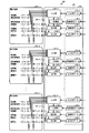
- FIG. 1 is a schematic configuration block diagram of a multi-system LFC system according to the first embodiment.
- FIG. 2 is a functional block diagram of the multi-system LFC system.
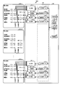
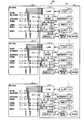
- FIG. 3 is a functional block diagram (before addition) showing the configuration of the multi-system LFC system of the second embodiment.
- FIG. 4 is a functional block diagram (after addition) showing the configuration of the multi-system LFC system of the second embodiment.
- FIG. 5 is a functional block diagram showing the configuration of the multi-system LFC system according to the third embodiment of the present invention.
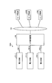
- FIG. 6 is a schematic configuration block diagram of the multi-system LFC system of the fourth embodiment.
- FIG. 7 is a process flowchart of the fourth embodiment.
- FIG. 8 is an explanatory diagram of a data recording example of the setting data recording unit of the fifth embodiment.
- FIG. 1 is a schematic configuration block diagram of a multi-system LFC system according to a first embodiment.
- the LFC system 100 for a plurality of systems according to the first embodiment can be broadly divided into a plurality of power systems (systems) 101-1 to 101-x having a storage battery system, a LFC management apparatus 102 for a plurality of systems, and a power system 101.
- -1 to 101-x and the LFC management apparatus 102 are communicably connected to each other, and communication networks 103-1 to 103-3 are provided.
- the power systems 101-1 to 101-x have the same configuration, the power system 101-1 will be described as an example.
- FIG. 2 is a functional block diagram of the multi-system LFC system.
- the LFC management apparatus 102 includes input units 121-1 to 121-x to which measurement data is input from the power systems 101-1 to 101-x, and a calculation unit 122-1 that calculates a supply and demand imbalance amount based on the measurement data.
- 122-x and distribution units 123-1 to 123- that calculate supply and demand imbalance amounts to be distributed to one or a plurality of generators and one or a plurality of storage batteries constituting the power systems 101-1 to 101-x.
- An output unit that outputs data for controlling one or a plurality of generators and one or a plurality of storage batteries constituting the power systems 101-1 to 101-x based on x and the allocated supply-demand imbalance amount 124-1 to 124-x, input data 131-1 to 131-x, system characteristic data 132-1 to 132-x, control data 133-1 to 133-x, and output data 134-1 to 1 Advance and stored data recording unit 125 the 4-x, and a.
- input data 131-1 to 131-x, system characteristic data 132-1 to 132-x, control data 133-1 to 133-x, and output data 134-1 to 134-x are data. It is assumed that the recording unit 125 is set before starting LFC for each of the power systems 101-1 to 101-x (system) by an external device (not shown).
- frequency data 113-1 corresponding to frequency measurement values from measurement points set in advance in the power systems 101-1 to 101-x, respectively.
- Storage battery output data 116-11 to 116-1n, 116-21 to 116-2n,..., 116-x1 to 116-xn corresponding to the measured values are input as uplink data.
- the measured values of the measurement points of the power systems 101-1 to 101-x are generally measured by the communication network 103-1 to 103 by a communication device represented by a remote monitoring control device (TC) or a cyclic digital information transmission device (CDT).
- TC remote monitoring control device
- CDT cyclic digital information transmission device
- 121-x when the input units 121-1, 121-2,..., 121-x input from the communication device, the input data 131-1, 131-2 ,..., 131-x can be used to identify each measured value.
- the input data 131-1, 131-2,..., 131-x which of the communication data sent from any of the transmission sources corresponds to each uplink data. Contains data to show.
- the calculation units 122-1 to 122-x are respectively frequency data 113-1, 113-1,..., 113- of the uplink information input by the input units 121-1, 121-2,.
- the supply and demand imbalance amount is calculated based on at least one of x or interconnected power flow data 114-11 to 114-1k, 114-21 to 114-2k, ..., 114-x1 to 114-xk .
- This supply and demand imbalance amount is called regional requirement amount in Japan, and is called Area Control Error (however, the sign is opposite to the regional requirement amount) in the United States.
- the calculation unit 122-1 obtains the constant K1 and the constant K2 of the power system 101-1 with reference to the system characteristic data 132-1 when calculating the supply and demand imbalance amount.
- the calculation units 122-2,..., And the calculation unit 122-x refer to the system characteristic data 132-1,.
- the number of interconnecting power flows in the power systems 101-1 to 101-x is all k, but for each system, that is, for each power system 101-1 to 101-x, The number may be different.
- the distribution units 123-1 to 123-x are the supply / demand imbalance amounts calculated by the corresponding calculation units 122-1 to 122-x and the generators input via the corresponding input units 121-1 to 121-x.
- the control amount may be corrected by multiplying the control amount of each generator and / or storage battery by a gain constant as necessary.
- the upper and lower limit values, gain constants, etc. used by the distribution units 123-1 to 123-x when calculating the controlled variable are stored as control data 133-1 to 133-x. For this reason, when the distribution units 123-1 to 123-x calculate the control amount, the control data 133-1,. To get to.
- the number of generators and storage batteries in the power systems 101-1 to 101-x is described as m and n, respectively, and the same number for all the power systems 101-1 to 101-x. It doesn't matter if they are different.
- the output units 124-1, 124-2,..., 124-x are the generator control amount data 117-11 to 117-1m calculated and output by the distribution units 123-1, 123-2,. , 17-21 to 117-2m, ..., 117-x1 to 117-xm, or storage battery control amount data 118-11 to 181-1n, 118-21 to 118-2n, ..., 118-x1 to 118-xn At least one of them is sent as downlink information to the control points of the power systems 101-1 to 101-x.
- the downlink information sent to the control points of the power systems 101-1 to 101-x is generally transmitted from the LFC management device by a communication device represented by a remote monitoring control device (TC) or a cyclic digital information transmission device (CDT). Since the output units 124a, 124-2, ..., 124-x are sent to the power plant or substation, each control variable is controlled by referring to the output data 134-1, 134-2, ..., 134-x. The data can be output to the corresponding communication device. In other words, the output data 134-1, 134-2,..., 134-x includes data indicating which data in the communication data to be sent to each piece of downlink information.
- the units 124-1, 124-2b,..., 124-x are configured to periodically operate at regular time intervals (for example, several seconds). In this way, the LFC management apparatus of the multi-system LFC system simultaneously maintains the frequencies of the power systems 101-1 to 101-x in parallel.
- the multi-system LFC system 100 of the first embodiment it is not necessary to construct an LFC system for each power system (system) 101-1 to 101-x, and a plurality of power systems 101 Since it is only necessary to provide one LFC management device 102 for multiple systems for -1 to 101-x (system), it can be built economically and can be centrally managed, reducing the number of maintenance personnel As well as the advantage of being economically maintainable.
- FIG. 3 is a functional block diagram (before addition) showing the configuration of the multi-system LFC system of the second embodiment.
- FIG. 4 is a functional block diagram (after addition) showing the configuration of the multi-system LFC system of the second embodiment.
- the multi-system LFC system 100A has a configuration excluding a configuration corresponding to the power system 101-2 from the multi-system LFC system 1 according to the first embodiment, a setting unit 141, a setting data recording unit 142, The data update unit 143 and the management unit 144 are added.
- the setting unit 141 sets as input data 131-1 to 131-x, system characteristic data 132-1 to 132-x, control data 133-1 to 133-x, and output data 134-1 to 134-x. Enter the setting data to do.
- the setting data recording unit 142 includes input data 131-1 to 131-x, system characteristic data 132-1 to 132-x, control data 133-1 to 133-x, and output data 134-1 to 134-x. Setting data for setting as is stored.
- the data update unit 143 is based on the input data 131-2, system characteristic data 132-2, control data 133-2, and output data.
- a data update process for adding and storing the data 134-2 to the data recording unit 125 is performed.
- the management unit 144 includes input units 121-1, 121-3 (not shown),..., 121-x, calculation units 122-1, 122-3 (not shown),. -1, 123-2,..., 123-x, and output units 124-1, 124-3 (not shown),.
- FIG. 3 shows a state where the LFC management apparatus 102 of the multi-system LFC system 100A controls the power system 101-1 and the power system 101-x.
- the setting unit 141 externally inputs data 131-2, system characteristic data 132-2, control data 133-2, and output necessary for maintaining the frequency of the new power system 101-2.
- the setting of the data 134-2 is received and recorded in the setting data recording unit 142.
- the setting data recording unit 142 receives the input data 131-2, the system characteristic data 132-2, the control data 133-2, and the output of the power system 101-2 that is a new system input from the setting unit 141. Data for generating the data for use 134-2 is stored.
- the management unit 144 When the management unit 144 receives an instruction from the outside to newly set the power system 101-2 as an LFC control target, the management unit 144 instructs the data update unit 143 to input data 131-2 of the power system 101-2 that is a new system. Instruct to create system characteristic data 132-2, control data 133-2, and output data 134-2.
- the management unit 144 generates an input unit 121-2, a calculation unit 122-2, a distribution unit 123-2, and an output unit 124-2 for the power system 101-2 that is a new system. However, at this time, the input unit 121-2, the calculation unit 122-2, the distribution unit 123-2, and the output unit 124-2 are not activated.
- the data updating unit 143 creates input data 131-2, system characteristic data 132-2, control data 133-2, and output data 134-2 for the power system 101-2 as a new system from the management unit 144.
- input data 131-2, system characteristic data 132-2, control data 133-2, and output data 134-2 of the power system 101-2 are generated, and the contents are recorded as setting data.
- the contents are the same as the contents of the input data 131-2, the system characteristic data 132-2, the control data 133-2, and the output data 134-2 of the power system 101-2 recorded in the unit 142.
- the management unit 144 activates the input unit 121-2, the calculation unit 122-2, the distribution unit 123-2, and the output unit 124-2 for the previously generated power system 101-2.
- the activated input unit 121-2, calculation unit 122-2, distribution unit 123-2, and output unit 124-2 operate periodically thereafter, and the multi-system LFC system 100A is shown in FIG. It becomes a state.
- the input units 121-1 to 121-x, the calculation units 122-1 to 122-x, the distribution units 123-1 to 123- shown in FIG. x and the output units 124-1 to 124 -x periodically move every predetermined time (for example, several seconds), and perform the same operation as the multi-system LFC system 100 of the first embodiment. It becomes.
- the frequency data 113-1 of the power system 101-1, the interconnection currents 114-11 to 114-1k, the generator output data 115-11 to 115-1m, or the storage battery output data 116-11 to 115- If there is an addition or change in the measurement point for acquiring 1n, or addition of a control point that is the output destination of the generator control amount data 117-11 to 117-1m or the storage battery control amount data 118-11 to 118-1n, The operation when there is a change will be described.
- the setting unit 141 includes input data 131-1, system characteristic data 132-1, and control data necessary for maintaining the frequency of the already registered power system 101-1.
- New setting data for changing the setting is input as 133-1 and output data 134-1.
- all of input data 131-1, system characteristic data 131-1, control data 133-1 and output data 134-1 are input, but only data that needs to be changed. You can enter.
- the setting data recording unit 142 receives the input data 131-1, the system characteristic data 132-1, the control data 133-1 and the output of the power system 101-1, which are newly input from the setting unit 141. Data for generating the data for use 134-1 is stored.
- the management unit 144 Upon receiving an instruction to update data corresponding to the power system 101-1, the management unit 144 updates the input data 131-1, the system characteristic data 132-1, the control data 133-1, and the output data 134-1. Prior to this, the input unit 121-1, the calculation unit 122-1, the distribution unit 123-1 and the output unit 124-1 are temporarily stopped so as not to perform a periodic operation (normal operation). Instructs the data updating unit 143 to create new input data 131-1, system characteristic data 132-1, control data 133-1 and output data 134-1 corresponding to the power system 101-1. To do.
- the data updating unit 143 creates new input data 131-1, power system characteristic data 132-1, control data 133-1 and output data 134-1 for the power system 101-1, from the management unit 144.
- the contents of the input data 131-1, the system characteristic data 132-1, the control data 133-1 and the output data 134-1 of the power system 101-1 are recorded in the setting data recording unit 142.
- the contents of the input data 131-1, system characteristic data 132-1, control data 133-1, and output data 134-1 of the power system 101-1 are updated.
- the management unit 144 activates the input unit 121-1, the calculation unit 122-1, the distribution unit 123-1 and the output unit 124-1 for the power system 101-1 that has been once stopped.
- the input unit 121-1, the calculation unit 122-1, the distribution unit 123-1, and the output unit 124-1 activated with the updated content operate periodically thereafter, and are the same as in the first embodiment. Perform the action.
- the LFC control of the power system 101-2 is stopped from the situation where the LFC control of the power systems 101-1 to 101-x is performed.
- the operation until the LFC control is performed for the power systems 101-1, 101-3 to 101-x will be described.
- the setting unit 141 includes input data 131-2, system characteristic data 132-2, and control data required for maintaining the frequency of the already registered power system 101-2. Accept deletion as 133-2 and output data 134-2, and input a deletion instruction.
- the setting data recording unit 142 receives the input data 131-2, the system characteristic data 132-2, the control data 133-2, and the output data for the power system 101-2 based on the deletion instruction input from the setting unit 141.
- the fact that the data for generating data 134-2 has been deleted is stored.
- the management unit 144 Upon receiving an instruction to exclude the power grid 101-2 from the LFC control target, the management unit 144 receives the input unit 121-2, the calculation unit 122-2, the distribution unit 123-2, and the output that have been periodically moved to the point in time. The unit 124-2 is stopped and deleted. Thereafter, the management unit 144 updates the input data 131-2, the system characteristic data 132-2, the control data 133-2, and the output data 134-2 of the power system 101-2 to the data update unit 143. Instruct them to do so.
- the data update unit 143 based on the instruction from the management unit 144, the input data 131-2, the system characteristic data 132-2, the control data 133-2, and the data recorded in the setting data recording unit 142, Although the contents of the output data 134-2 are to be updated, since the fact that these data are deleted is recorded in the setting data recording unit 142, the input data 131-2, system An operation for deleting the characteristic data 132-2, the control data 133-2, and the output data 134-2 is performed.
- the LFC management apparatus 102 of the multi-system LFC system 100A the state shown in FIG. 3 is obtained, and the input units 121-1, 121-3 to 121-x, and the calculation units 122-1, 122-3 to 122- x, the distribution units 123-1, 123-3 to 123-x, and the output units 124-1, 124-3 to 124-x move periodically every predetermined time (for example, several seconds),
- the power systems 101-1 and 101-3 to 101-x perform the same operation as in the first embodiment.
- FIG. 5 is a functional block diagram showing the configuration of an LFC system for multiple systems according to a third embodiment of the present invention.
- the multi-system LFC system 100B of the third embodiment is different from the multi-system LFC system 100 of the first embodiment of FIG. 1 in that the input units 121-1 to 121-x constituting the LFC management apparatus 102. , Control status data recording units 125-1 to 125-x for recording control status data of the calculation units 122-1 to 122-x, the distribution units 123-1 to 123-x, and the output units 124-1 to 124-x, Control status display sections 135-1 to 135-x for displaying the control status on the display sections 147-1 to 147-x based on the recording status of the control status data recording sections 125-1 to 125-x, respectively. It is.
- the input units 121-1 to 121-x record the input uplink information in the control status data recording units 125-1 to 125-x, respectively.
- the calculation units 122-1 to 122-x record the calculated supply and demand imbalance amounts in the control status data recording units 125-1 to 125-x, respectively.
- the distribution units 123-1 to 123-x record the calculated control amounts in the control status data recording units 125-1 to 125-x, respectively.
- the output units 124-1 to 124-x record the downlink information output by each of them in the control status data recording units 125-1 to 125-x.
- control status display units 135-1 to 135-x indicate the control statuses to the display units 147-1 to 147-x based on the recording statuses of the control status data recording units 125-1 to 125-x, respectively. indicate.
- the multi-system LFC system 100B of the third embodiment while performing LFC control of a plurality of systems, that is, the power systems 101-1 to 101-x, for each of the power systems 101-1 to 101-x, Since the LFC control status can be displayed, the operator of the LFC management apparatus 102 can know the LFC control status for each of the power systems 101-1 to 101-x.
- TC remote monitoring control device
- CDT cyclic digital information transmission device
- the system in the multi-system LFC systems 100 to 100B, by adopting the Internet protocol as the communication protocol for uplink information or downlink information, the system can be constructed more easily. The degree of freedom of communication can be improved, and the system construction cost can be reduced.
- a communication protocol that can be encrypted is adopted, communication is performed after encryption, virtual private network (VPN) It is preferable to carry out via
- VPN virtual private network
- encoding / decoding at the time of encryption is preferably performed by hardware rather than by software.
- FIG. 6 is a schematic configuration block diagram of a multi-system LFC system according to a fourth embodiment.
- the difference from the multi-system LFC system of the first to third embodiments is that the multi-system LFC system 100A is used via the LFC management apparatus 102 and the second communication network (for example, the Internet).
- the user terminal of a user (including a pre-contract user) is connected.
- a server is connected, or the LFC management apparatus 102 is connected via a local second communication network (including a case where connection is made with a connection cable).
- a user terminal may be connected.
- the multi-system LFC system 100A is roughly classified into a plurality of power systems 101-1 to 101-x, a multi-system LFC management apparatus 102, and power systems 101-1 to 101-x.
- a plurality of user terminals 105A to 105C connected via the communication networks 103-1 to 103-3, the second communication network 104, and the second communication network 104, which are communicably connected to the LFC management apparatus 102, respectively. And.
- FIG. 7 is a process flowchart of the fourth embodiment.
- the site provided by the LFC function provider is, for example, the Internet
- the user terminal 105A is connected to the LFC management apparatus 102 via the constructed second communication network 104.
- the pre-contract user makes a new contract application for receiving the provision of the LFC function (step S1; contract step).
- the multi-system LFC system 100A determines whether the application content in the contract step is a new contract, a contract revision, or a contract end (step S2).
- step S1 new contract
- the multi-system LFC is received from the user terminal 105A. Connect to the setting unit 141 of the system 100A.
- step S3a data setting for using the LFC function for the new power system (new system) is performed on the setting unit 141 (step S3a).
- the setting unit 141 uses the LFC function for a new power system (new system) to input data necessary for maintaining the frequency corresponding to the new power system.
- the system characteristic data, control data, and output data settings are received and recorded in the setting data recording unit 142.
- the setting data recording unit 142 stores input data for the new power system, system characteristic data, control data, and output data generation data input from the setting unit 141.
- the multi-system LFC system 100A generates LFC data for starting the LFC function in the new system (step S4a). Specifically, upon receiving an instruction from the user terminal 105A that the power system is newly set as an LFC control target, the management unit 144 receives the data update unit 143 from the input data for the power system that is a new system. Instruct to create system characteristic data, control data and output data.
- the management unit 144 generates an input unit, a calculation unit, a distribution unit, and an output unit for a power system that is a new system, and sets the standby state without starting.
- the data updating unit 143 When the data updating unit 143 receives an instruction from the management unit 144 to create input data, system characteristic data, control data, and output data for a power system that is a new system, the newly added power System input data, system characteristic data, control data, and output data are generated, and the contents are recorded in the setting data recording unit 142. Power system input data, system characteristic data, control data, and output The content is the same as the content of the business data.
- the management unit 144 includes the input unit for the previously generated power system, Starts the calculation unit, distribution unit, and output unit.
- the multi-system LFC system 100A shifts to an LFC execution step in which the LFC function is continuously performed in the new system (step S5a).
- the activated input unit, calculation unit, distribution unit, and output unit periodically perform the same operation as that of the multiple-capacity LFC system 100 of the first embodiment.
- step S1 contract revision
- step S2 contract revision step
- step S2 contract revision
- step S3b processing is performed as in the case of changing the LFC control conditions.
- the user terminal 105 ⁇ / b> A via the setting unit 141 can newly input a contract for revision as input data, system characteristic data, control data, and output data necessary for maintaining the frequency of the already registered power system. Enter the correct setting data.
- the setting data recording unit 142 stores input data for the power system to be newly set, system characteristic data, control data, and output data generation data input from the setting unit 141.
- the multi-system LFC system 100A shifts to the LFC data switching step of switching the LFC data for realizing the LFC function in the existing system of the user corresponding to the user terminal 105A to switch the LFC data after the contract revision (step S4b).
- the management unit 144 When the management unit 144 receives an update instruction (revision instruction) for data corresponding to the power system, the management unit 144 provides the data update unit 143 with new input data, system characteristic data, control data, and output corresponding to the power system. Instruct to create data.
- the data updating unit 143 receives an instruction from the management unit 144 to create new input data, system characteristic data, control data, and output data for the existing power system, before the power system contract is revised.
- the corresponding input unit, calculation unit, distribution unit, and output unit are temporarily stopped, and then the contents of the power system input data, system characteristic data, control data, and output data are recorded in the setting data recording unit 142
- the contents are updated to the same contents as the contents of the input data, system characteristic data, control data, and output data of the power system corresponding to the user who is making the contract revision.
- the management unit 144 is in the suspended state after the contract revision. The input unit, calculation unit, distribution unit, and output unit for the new power system are activated.
- the LFC management apparatus 102 of the multi-system LFC system 100A shifts to an LFC execution step for continuously executing a new LFC function after the contract revision (step S5b).
- the input unit, the calculation unit, the distribution unit, and the output unit activated after the contract revision operate periodically thereafter, and perform the same operation as in the first embodiment.
- the contract user applies for contract termination using the user terminal 105A (step S1; contract step).
- the LFC management apparatus 102 of the multi-system LFC system 100A determines whether the application content in the contract step is a new contract, contract revision, or contract termination (step S2).
- step S2 contract terminated
- the LFC management apparatus 102 performs the same process as in the case of stopping the LFC control in the second embodiment described above. Then, the contract user uses the user terminal 105A to delete the input data, system characteristic data, control data, and output data necessary for maintaining the frequency of the already registered power system to the setting unit 141. Enter instructions.
- the contract user uses the user terminal 105 ⁇ / b> A to the setting unit 141 to terminate the contract, so that the power system input data, system characteristic data, necessary for maintaining the frequency of the already registered power system,
- the process proceeds to a maintenance step for deleting the control data and output data (step S3c).
- the setting unit 141 of the LFC management apparatus 102 has already been registered, and the input data, system characteristic data, control data, and output data necessary for maintaining the frequency of the power system that is the target of contract termination are stored.
- a deletion instruction is input to the setting data recording unit 142.
- the setting data recording unit 142 of the LFC management apparatus 102 generates input data, system characteristic data, control data, and output data for the power system to be terminated based on the deletion instruction input from the setting unit 141. Remember that was deleted.
- the LFC management apparatus 102 of the multi-system LFC system 100A shifts to an LFC end step for ending the LFC function provision contract in the user's existing system corresponding to the user terminal 105A (step S4c).
- the management unit 144 of the LFC management apparatus 102 When the management unit 144 of the LFC management apparatus 102 receives an instruction to terminate the contract of the power system to be contract terminated (effectively excluded from the LFC control target), the input unit that has been moving periodically until that time, calculation The unit, the distribution unit, and the output unit are stopped and deleted.
- the management unit 144 of the LFC management apparatus 102 instructs the data update unit 143 to update the input data, the system characteristic data, the control data, and the output data of the power system subject to contract termination.
- the data update unit 143 attempts to update the contents of the input data, system characteristic data, control data, and output data recorded in the setting data recording unit 142 based on an instruction from the management unit 144.
- the setting data recording unit 142 records that these data have been deleted, an operation for effectively deleting the input data, system characteristic data, control data, and output data is performed. Do.
- the provision of the LFC function to the power system after the contract is terminated.
- the provision of the LFC function to the remaining power system continues, and the input unit, calculation unit, distribution unit, and output unit of the remaining power system operate periodically thereafter, and are the same as in the first embodiment. Perform the action.
- the LFC function provider starts providing the LFC function as a service to a plurality of specific system LFC operators (users).
- the LFC function can be provided as a service by revising the contract (changing the operating conditions).
- the end of provision of the LFC function service can be performed using the multi-system LFC system.
- the user terminal is directly connected to the LFC management apparatus via the second communication network (Internet).
- a contract management server is provided, and the contract management server is used as an external device of the LFC management apparatus. It is also possible to configure to perform similar processing.
- the set data of each power system 101-1 to 101-x (system) stored in the setting data recording unit 142 is one set each.
- the fifth embodiment is an embodiment in which a plurality of sets of setting data of each power system 101-1 to 101-x (system) stored in the setting data recording unit 142 is stored.
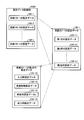
- FIG. 8 is an explanatory diagram of a data recording example of the setting data recording unit of the fifth embodiment. Note that the configuration of the multi-system LFC system of the fifth embodiment is the same as that in the case of FIG. 3, and the detailed description thereof is incorporated.
- the setting data recording unit 142A of the fifth embodiment is recorded with the generation identifier for each power system 101-1 to 101-x (system) with each past change.
- the power system is represented as a system for simplification of illustration.
- the power system 101-1 is a specific system, and input for the power system 101-1. Changes to the data 131-1, system characteristic data 132-1, control data 133-1 and output data 134-1 are accepted.
- the received content is recorded in the setting data recording unit 142A as the setting data 130-1 of the power system 101-1
- the generation data 133-2 and the output data 134-2 are recorded with an identifier indicating a generation (in the example of FIG. 8, an identifier indicating the (j-1) th generation), and the changed input data 131-2, the system characteristic data 132-2, the control data 133-2, and the output data 134-2 are also attached with identifiers indicating generations (in the example of FIG. 8, identifiers indicating the jth generation).
- identifiers indicating generations in the example of FIG. 8, identifiers indicating the jth generation.
- the input data 131-1 of the power system 101-1, the system characteristic data 132-1, the control data 133-1 and the output data 134-1 are changed.
- the input setting data 131-1S, the system characteristic setting data 132-1S, the control setting data 133-1S, and the output setting data 134-1S of the power system 101-1 that are input to receive the power are stored.
- the deletion of the input data 131-1, the system characteristic data 132-1, the control data 133-1 and the output data 134-1 of the power system 101-1, which is a specific system that has already been set, is accepted.
- the received contents are recorded in the setting data recording unit 142A, the latest input data 131-1, system characteristic data 132-1, control data 133-1 and output data 134-1 are generated.
- the identifier indicating the (j ⁇ 1) generation) is recorded and recorded, and the input data 131-2, the system characteristic data 132-2, and the control data after the change are recorded.
- 133-2 and output data 134-2 are also recorded with an identifier indicating the generation (in the example of FIG. 8, an identifier indicating the jth generation).
- the first generation setting data 130-11 to the jth generation setting data 130-1j are stored as the setting data of the power system 101-1, as in the case of receiving the change.
- the management unit 144 determines that the currently operating input unit 121-1, The operation of the unit 122-1, the distribution unit 123-1, and the output unit 124-1 is temporarily stopped, and then the power system 101, which is a specific system recorded in the setting data recording unit 142A, is transmitted to the data update unit 143.
- Input data 131-1 based on input setting data, system characteristic setting data, control setting data, and output setting data corresponding to setting data of a specified generation of ⁇ 1 (for example, the (j ⁇ 1) th generation setting data) And instructing to update the system characteristic data 132-1, the control data 133-1 and the output data 134-1.
- the data update unit 143 receives the setting data for the (j ⁇ 1) generation of the power system 101-1 recorded in the setting data recording unit 142A, the system characteristic setting The input data 131-1, the system characteristic data 132-1, the control data 133-1 and the output data 134-1 of the power system 101-1 are updated according to the contents of the data, control setting data, and output setting data. To do.
- the management unit 144 activates the input unit 121-1, the calculation unit 122-1, the distribution unit 123-1, and the output unit 124-1. Thereafter, the input unit 121-1, the calculation unit 122-1, the distribution unit 123-1, and the output unit 124-1 move periodically.
- LFC control can be easily performed under the conditions before the change, and when there is an error in the setting data, the input data 131-1, This can be easily handled when it is desired to perform the LFC control by returning the system characteristic data 132-1, the control data 133-1 and the output data 134-1 to the previous generation state.
- the LFC management device of the present embodiment includes a control device such as a CPU, a storage device such as a ROM (Read Only Memory) and a RAM, an external storage device such as an HDD and a CD drive device, a display device such as a display device, It has an input device such as a keyboard and a mouse, and has a hardware configuration using a normal computer.
- a control device such as a CPU
- a storage device such as a ROM (Read Only Memory) and a RAM
- an external storage device such as an HDD and a CD drive device
- a display device such as a display device
- It has an input device such as a keyboard and a mouse, and has a hardware configuration using a normal computer.
- the program executed by the LFC management apparatus of the present embodiment is an installable format or executable format file, such as a CD-ROM, flexible disk (FD), CD-R, or DVD (Digital Versatile Disk). It is recorded on a readable recording medium and provided.
- an installable format or executable format file such as a CD-ROM, flexible disk (FD), CD-R, or DVD (Digital Versatile Disk). It is recorded on a readable recording medium and provided.
- the program executed by the LFC management apparatus of the present embodiment may be stored on a computer connected to a network such as the Internet and provided by being downloaded via the network.
- the program executed by the LFC management apparatus according to the present embodiment may be provided or distributed via a network such as the Internet.
- the LFC management apparatus program of the present embodiment may be provided by being incorporated in advance in a ROM or the like.
- the program executed by the LFC management apparatus of the present embodiment has a module configuration including the above-described units (input unit, calculation unit, distribution unit, output unit, setting unit, data update unit, management unit).
- the CPU reads the program from the storage medium and executes it to load the above-mentioned units onto the main storage device, and the input unit, calculation unit, distribution unit, output unit, setting unit, data An update unit and a management unit are generated on the main storage device.
Landscapes
- Engineering & Computer Science (AREA)
- Power Engineering (AREA)
- Supply And Distribution Of Alternating Current (AREA)
- Remote Monitoring And Control Of Power-Distribution Networks (AREA)
Abstract
発電機及び蓄電池システムのうち、少なくともいずれか一方を有する複数の電力系統のそれぞれに対し、LFC制御の管理を行うLFC管理装置のデータ記録部は、複数の電力系統のそれぞれに対応するデータを更新可能に予め記憶し、複数の入力部は、系統毎の入力用データに基づいて、複数の電力系統のそれぞれから計測データが入力され、複数の計算部は、系統毎の系統特性データ及び計測データに基づいて需給アンバランス量を算出し、複数の配分部は、系統毎の制御用データ、計測データ及び需給アンバランス量に基づいて、発電機及び蓄電池システムのうち少なくともいずれか一方への需給アンバランス量の配分を算出し、複数の出力部は、系統毎の出力用データ及び配分された需給アンバランス量に基づいて、発電機あるいは蓄電池システムの制御用のデータを出力するので、複数の電力系統(系統)に対してLFC機能を提供することができる。
Description
本発明の実施形態は、LFC管理装置、LFCシステム、方法及びプログラムに関する。
地球温暖化対策を目指して太陽光や風力等の再生可能エネルギーを導入すると共に賢く電気エネルギーを管理するスマートグリッドは、今後ますます促進されることが予想される。
しかし再生可能エネルギーは出力が不安定のために大量に導入した場合の問題として系統の周波数調整能力つまりLFC調整力の不足が懸念されている。これは、電源に占める再生可能エネルギーの比率が高くなると、相対的に火力・水力発電などのLFC調整力を持つ電源の比率が低下し、ある程度以上には再生可能エネルギーの比率を上げることができなくなるからである。
しかし再生可能エネルギーは出力が不安定のために大量に導入した場合の問題として系統の周波数調整能力つまりLFC調整力の不足が懸念されている。これは、電源に占める再生可能エネルギーの比率が高くなると、相対的に火力・水力発電などのLFC調整力を持つ電源の比率が低下し、ある程度以上には再生可能エネルギーの比率を上げることができなくなるからである。
これを解決するための手段として、例えば、蓄電池を導入し、蓄電池に再生可能エネルギーの出力変動を吸収させたり、系統の需要と供給のアンバランスを吸収させたりすることが提案されている。
ところで、再生可能エネルギーを導入してスマートグリッドを構築することも、近年盛んに検討されており、今後ますます増加する事が予想される。
しかしながら、新たに再生可能エネルギーを導入して電力系統を構築する場合や、一部の電力系統に再生可能エネルギーを導入して当該一部の系統を本系統とは別に周波数維持を行う場合等には、当該系統の周波数を維持する機能(LFC機能)を持つLFCシステムを構築する必要があり、構築コスト及び維持コストが増大する虞があった。
本発明は、上記に鑑みてなされたものであって、複数の電力系統(系統)に対してLFC機能を提供することが可能なLFC管理装置、LFCシステム、方法及びプログラムを提供することを目的としている。
しかしながら、新たに再生可能エネルギーを導入して電力系統を構築する場合や、一部の電力系統に再生可能エネルギーを導入して当該一部の系統を本系統とは別に周波数維持を行う場合等には、当該系統の周波数を維持する機能(LFC機能)を持つLFCシステムを構築する必要があり、構築コスト及び維持コストが増大する虞があった。
本発明は、上記に鑑みてなされたものであって、複数の電力系統(系統)に対してLFC機能を提供することが可能なLFC管理装置、LFCシステム、方法及びプログラムを提供することを目的としている。
LFC管理装置は、発電機及び蓄電池システムのうち、少なくともいずれか一方を有する複数の電力系統のそれぞれに対し、LFC制御の管理を行う。
これに際し、データ記録部に複数の電力系統のそれぞれに対応する入力用データ、系統特性データ、制御用データ及び出力用データを更新可能に予め記憶する。
これにより、複数の入力部は、系統毎の入力用データに基づいて、複数の電力系統のそれぞれから計測データが入力される。
複数の計算部は、系統毎の系統特性データ及び計測データに基づいて需給アンバランス量を算出する。
複数の配分部は、電力系統毎の制御用データ、前記計測データ及び前記需給アンバランス量に基づいて、発電機及び蓄電池システムのうち少なくともいずれか一方への需給アンバランス量の配分を算出する。
複数の出力部は、系統毎の出力用データ及び配分された需給アンバランス量に基づいて、発電機あるいは蓄電池システムの制御用のデータを出力する。
これに際し、データ記録部に複数の電力系統のそれぞれに対応する入力用データ、系統特性データ、制御用データ及び出力用データを更新可能に予め記憶する。
これにより、複数の入力部は、系統毎の入力用データに基づいて、複数の電力系統のそれぞれから計測データが入力される。
複数の計算部は、系統毎の系統特性データ及び計測データに基づいて需給アンバランス量を算出する。
複数の配分部は、電力系統毎の制御用データ、前記計測データ及び前記需給アンバランス量に基づいて、発電機及び蓄電池システムのうち少なくともいずれか一方への需給アンバランス量の配分を算出する。
複数の出力部は、系統毎の出力用データ及び配分された需給アンバランス量に基づいて、発電機あるいは蓄電池システムの制御用のデータを出力する。
以下、本発明の実施形態について、図面を参照して具体的に説明する。
[1]第1実施形態
図1は、第1実施形態の複数系統用LFCシステムの概要構成ブロック図である。
第1実施形態の複数系統用LFCシステム100は、大別すると、蓄電池システムを有する複数の電力系統(系統)101-1~101-xと、複数系統用のLFC管理装置102と、電力系統101-1~101-xとLFC管理装置102とをそれぞれ通信可能に接続する通信ネットワーク103-1~103-3と、を備えている。
ここで、電力系統101-1~101-xは、同様の構成であるので、電力系統101-1を例として説明する。
[1]第1実施形態
図1は、第1実施形態の複数系統用LFCシステムの概要構成ブロック図である。
第1実施形態の複数系統用LFCシステム100は、大別すると、蓄電池システムを有する複数の電力系統(系統)101-1~101-xと、複数系統用のLFC管理装置102と、電力系統101-1~101-xとLFC管理装置102とをそれぞれ通信可能に接続する通信ネットワーク103-1~103-3と、を備えている。
ここで、電力系統101-1~101-xは、同様の構成であるので、電力系統101-1を例として説明する。
図2は、複数系統用LFCシステムの機能ブロック図である。
LFC管理装置102は、電力系統101-1~101-xから計測データが入力される入力部121-1~121-xと、計測データに基づいて需給アンバランス量を算出する計算部122-1~122-xと、電力系統101-1~101-xを構成している一又は複数の発電機及び一又は複数の蓄電池に配分する需給アンバランス量を算出する配分部123-1~123-xと、配分された需給アンバランス量に基づいて、電力系統101-1~101-xを構成している一又は複数の発電機及び一又は複数の蓄電池の制御用のデータを出力する出力部124-1~124-xと、入力用データ131-1~131-x、系統特性データ132-1~132-x、制御用データ133-1~133-x及び出力用データ134-1~134-xを予め記憶したデータ記録部125と、を備えている。
LFC管理装置102は、電力系統101-1~101-xから計測データが入力される入力部121-1~121-xと、計測データに基づいて需給アンバランス量を算出する計算部122-1~122-xと、電力系統101-1~101-xを構成している一又は複数の発電機及び一又は複数の蓄電池に配分する需給アンバランス量を算出する配分部123-1~123-xと、配分された需給アンバランス量に基づいて、電力系統101-1~101-xを構成している一又は複数の発電機及び一又は複数の蓄電池の制御用のデータを出力する出力部124-1~124-xと、入力用データ131-1~131-x、系統特性データ132-1~132-x、制御用データ133-1~133-x及び出力用データ134-1~134-xを予め記憶したデータ記録部125と、を備えている。
この場合において、入力用データ131-1~131-x、系統特性データ132-1~132-x、制御用データ133-1~133-x及び出力用データ134-1~134-xは、データ記録部125に対し、図示しない外部装置により、電力系統101-1~101-x(系統)毎にLFCを開始する前に設定されるものとする。
次に第1実施形態の動作を説明する。
まず、入力部121-1、121-2、…、121-xには、それぞれ電力系統101-1~101-xに予め設定された計測点から周波数の計測値に相当する周波数データ113-1、113-2、…、113-x、潮流の計測値に相当する連系線潮流データ114-11~114-1k、114-21~114-2k、…、114-x1~114-xk、発電機出力の計測値に相当する発電機出力データ115-11~115-1m、115-21~115-2m、…、115-x1~115-xm、蓄電池システムを構成している蓄電池の蓄電池出力の計測値に相当する蓄電池出力データ116-11~116-1n、116-21~116-2n、…、116-x1~116-xnが上りデータとして入力される。
まず、入力部121-1、121-2、…、121-xには、それぞれ電力系統101-1~101-xに予め設定された計測点から周波数の計測値に相当する周波数データ113-1、113-2、…、113-x、潮流の計測値に相当する連系線潮流データ114-11~114-1k、114-21~114-2k、…、114-x1~114-xk、発電機出力の計測値に相当する発電機出力データ115-11~115-1m、115-21~115-2m、…、115-x1~115-xm、蓄電池システムを構成している蓄電池の蓄電池出力の計測値に相当する蓄電池出力データ116-11~116-1n、116-21~116-2n、…、116-x1~116-xnが上りデータとして入力される。
電力系統101-1~101-xの計測点の計測値は、一般に遠方監視制御装置(TC)やサイクリックディジタル情報伝送装置(CDT)などに代表される通信装置によって通信ネットワーク103-1~103-3を介して、LFC管理装置102へ送られるため、入力部121-1、121-2、…、121-xが、通信装置から入力する際には入力用データ131-1、131-2、…、131-xを参照することによって各計測値を識別できるようになっている。つまり、入力用データ131-1、131-2、…、131-xには、上りデータ毎に、いずれかの送信元から送られてくる通信データの中のどのデータに対応しているのかを示すデータが含まれている。
計算部122-1~122-xは、それぞれ入力部121-1、121-2、…、121-xが入力した上り情報のうちのそれぞれ周波数データ113-1、113-1、…、113-x、あるいは、連系線潮流データ114-11~114-1k、114-21~114-2k、…、114-x1~114-xkのうちいずれか少なくとも一方に基づいて需給アンバランス量を算出する。
例えば、計算部122-1は、電力系統101-1の需給アンバランス量を、K1・(周波数データ113-1に対応する周波数-基準周波数)+K2・Σ(連系線潮流計画値1i-連系線潮流データ114-1i)(i=1~k)により計算する。この需給アンバランス量は、日本では、地域要求量と呼ばれ、米国ではArea Control Error(ただし地域要求量と符号が反対)と呼ばれている。
例えば、計算部122-1は、電力系統101-1の需給アンバランス量を、K1・(周波数データ113-1に対応する周波数-基準周波数)+K2・Σ(連系線潮流計画値1i-連系線潮流データ114-1i)(i=1~k)により計算する。この需給アンバランス量は、日本では、地域要求量と呼ばれ、米国ではArea Control Error(ただし地域要求量と符号が反対)と呼ばれている。
ここで、需給アンバランス量を算出する際に、連系線がない場合や連系線を考慮しない場合や周波数を考慮しない場合も、系統(電力系統)によってあり得るが、いずれの場合であってもかまわない。
上述した需給アンバランス量の計算式における定数K1や定数K2は、系統(電力系統)に依存する定数である。例えば、系統として電力系統101-1の場合を例とすると、系統特性データ132-1として記憶されている。そのため計算部122-1が、需給アンバランス量を算出する際には系統特性データ132-1を参照して電力系統101-1の定数K1や定数K2を取得するようになっている。
計算部122-2、…、計算部122-xも同様に、系統特性データ132-1、…、132-xを参照して系統としての需給アンバランス量を算出する。
以上の説明では、電力系統101-1~101-xの連系線潮流の数が全てk個である場合を説明したが、系統毎、すなわち、電力系統101-1~101-x毎にその数が異なっても良い。
上述した需給アンバランス量の計算式における定数K1や定数K2は、系統(電力系統)に依存する定数である。例えば、系統として電力系統101-1の場合を例とすると、系統特性データ132-1として記憶されている。そのため計算部122-1が、需給アンバランス量を算出する際には系統特性データ132-1を参照して電力系統101-1の定数K1や定数K2を取得するようになっている。
計算部122-2、…、計算部122-xも同様に、系統特性データ132-1、…、132-xを参照して系統としての需給アンバランス量を算出する。
以上の説明では、電力系統101-1~101-xの連系線潮流の数が全てk個である場合を説明したが、系統毎、すなわち、電力系統101-1~101-x毎にその数が異なっても良い。
配分部123-1~123-xは、対応する計算部122-1~122-xが算出した需給アンバランス量と、対応する入力部121-1~121-xを介して入力された発電機出力データ115-11~115-1m、115-21~115-2m、…、115x1~115xm、あるいは、蓄電池出力データ116-11~116-1n、116-21~115-2n、…、115x1~115xnのうち、少なくともいずれか一方に基づいて、発電機制御量データ117-11~117-1m、117-21~117-2m、…、117-x1~117-xm、あるいは、蓄電池制御量データ118-11~118-1n、118-21~118-2n、…、118-x1~118-xnのうち、少なくとも一方を算出する。
この場合において、配分部123-1~123-xの算出(計算)方法としては、各種方法が考えられるが、考えられる方法のうち、いずれの方法を採用することも可能である。
代表的な方法としては、各発電機や蓄電池の出力上下限値または放電電力上限値・充電電力上限値までの余裕量に応じて比例配分する方法が挙げられる。より詳細には、需給アンバランス量が電力不足を示す時は、各発電機出力から出力上限値まで、あるいは各蓄電池出力から放電電力上限値までの余裕量を計算して、その余裕量により比例配分する方法が可能である。
これらの場合において、適切な制御を実現するために必要によって各発電機または蓄電池またはその両方の制御量にゲイン定数を乗じて制御量を補正してもよい。
配分部123-1~123-xが、制御量を計算する際に用いる発電機や蓄電池の上下限値やゲイン定数等は、制御用データ133-1~133-xとして記憶されている。
このため、配分部123-1~123-xが制御量を計算する際に、制御用データ133-1、…、133-xをそれぞれ参照して発電機や蓄電池の上下限値やゲイン定数等を得るようになっている。
ここで電力系統101-1~101-xの発電機と蓄電池の数をそれぞれm台およびn台と、電力系統101-1~101-xの全系統について同じ台数として説明したが、系統毎に異なってもかまわない。
代表的な方法としては、各発電機や蓄電池の出力上下限値または放電電力上限値・充電電力上限値までの余裕量に応じて比例配分する方法が挙げられる。より詳細には、需給アンバランス量が電力不足を示す時は、各発電機出力から出力上限値まで、あるいは各蓄電池出力から放電電力上限値までの余裕量を計算して、その余裕量により比例配分する方法が可能である。
これらの場合において、適切な制御を実現するために必要によって各発電機または蓄電池またはその両方の制御量にゲイン定数を乗じて制御量を補正してもよい。
配分部123-1~123-xが、制御量を計算する際に用いる発電機や蓄電池の上下限値やゲイン定数等は、制御用データ133-1~133-xとして記憶されている。
このため、配分部123-1~123-xが制御量を計算する際に、制御用データ133-1、…、133-xをそれぞれ参照して発電機や蓄電池の上下限値やゲイン定数等を得るようになっている。
ここで電力系統101-1~101-xの発電機と蓄電池の数をそれぞれm台およびn台と、電力系統101-1~101-xの全系統について同じ台数として説明したが、系統毎に異なってもかまわない。
出力部124-1、124-2、…、124-xは、配分部123-1、123-2、…、123-xが算出し、出力した発電機制御量データ117-11~117-1m、17-21~117-2m、…、117-x1~117-xm、あるいは、蓄電池制御量データ118-11~181-1n、118-21~118-2n、…、118-x1~118-xnのうち、少なくともいずれか一方を下り情報としてそれぞれ電力系統101-1~101-xの制御点へ送る。
ところで、電力系統101-1~101-xの制御点へおくる下り情報は、一般に遠方監視制御装置(TC)やサイクリックディジタル情報伝送装置(CDT)などに代表される通信装置によってLFC管理装置から発電所や変電所へ送られるため、出力部124a、124-2、…、124-xは、出力用データ134-1、134-2、…、134-xを参照することによって各制御量をそれぞれに応じた通信装置へ出力できるようになっている。つまり、出力用データ134-1、134-2、…、134-xには、下り情報毎にどこへ送る通信データの中のどのデータに対応しているのかを示すデータが含まれている。
一般に入力部121-1、121-2、…、121-x、計算部122-1、122-2、…、122-x、配分部123-1、123-2、…、123-x、出力部124-1、124-2b、…、124-xは、一定時間間隔(たとえば、数秒)毎に周期的に動作するようにされている。
このようにして、複数系統用LFCシステムのLFC管理装置は、電力系統101-1~101-xの周波数維持を同時並列して行う。
このようにして、複数系統用LFCシステムのLFC管理装置は、電力系統101-1~101-xの周波数維持を同時並列して行う。
以上の説明のように、第1実施形態の複数系統用LFCシステム100によれば、電力系統(系統)101-1~101-x毎にLFCシステムを構築する必要がなく、複数の電力系統101-1~101-x(系統)に対して複数系統用のLFC管理装置102を一つ設ければよいため、経済的に構築できるというメリットに加え、集中管理が行えるため、保守要員数を抑制できるとともに、経済的に保守できるというメリットが得られる。
[2]第2実施形態
上記第1実施形態においては、予め系統(電力系統)が定まっている場合について説明したが、本第2実施形態は、一つのLFC管理装置において、系統(電力系統)を追加可能とした場合の実施形態である。
図3は、第2実施形態の複数系統用LFCシステムの構成を示す機能ブロック図(追加前)である。
図4は、第2実施形態の複数系統用LFCシステムの構成を示す機能ブロック図(追加後)である。
上記第1実施形態においては、予め系統(電力系統)が定まっている場合について説明したが、本第2実施形態は、一つのLFC管理装置において、系統(電力系統)を追加可能とした場合の実施形態である。
図3は、第2実施形態の複数系統用LFCシステムの構成を示す機能ブロック図(追加前)である。
図4は、第2実施形態の複数系統用LFCシステムの構成を示す機能ブロック図(追加後)である。
第2実施形態の複数系統用LFCシステム100Aは、第1実施形態の複数系統用LFCシステム1から電力系統101-2に対応する構成を除いた構成に、設定部141、設定データ記録部142、データ更新部143及び管理部144を追加した構成になっている。
設定部141は、入力用データ131-1~131-x、系統特性データ132-1~132-x、制御用データ133-1~133-x及び出力用データ134-1~134-xとして設定するための設定データを入力する。
設定データ記録部142は、入力用データ131-1~131-x、系統特性データ132-1~132-x、制御用データ133-1~133-x及び出力用データ134-1~134-xとして設定するための設定データを記憶する。
データ更新部143は、設定部141が入力し、設定データ記録部142に記憶した設定データに基づいて、入力用データ131-2、系統特性データ132-2、制御用データ133-2及び出力用データ134-2をデータ記録部125に追加して格納するデータ更新処理を行う。
管理部144は、入力部121-1、121-3(図示せず)、…、121-x、計算部122-1、122-3(図示せず)、…、122-x、配分部123-1、123-2、…、123-x、出力部124-1、124-3(図示せず)、…、124-xを管理する。
ここで、新たに電力系統101-2を複数系統用LFCシステム100Aを構成している複数系統用のLFC管理装置102に制御させる場合の登録の手順について説明する。
図3は、複数系統用LFCシステム100AのLFC管理装置102が、電力系統101-1及び電力系統101-xの制御を行っている状態を示している。
図3の状態において、設定部141は、外部から新たな電力系統101-2の周波数維持のために必要な入力用データ131-2、系統特性データ132-2、制御用データ133-2及び出力用データ134-2の設定を受け付けて設定データ記録部142へ記録する。
これにより設定データ記録部142には、設定部141から入力された新たな系統である電力系統101-2の入力用データ131-2、系統特性データ132-2、制御用データ133-2及び出力用データ134-2の生成用データが記憶される。
管理部144は、外部から電力系統101-2を新たにLFC制御対象とする指示を受け付けると、データ更新部143に対して、新たな系統である電力系統101-2の入力用データ131-2、系統特性データ132-2、制御用データ133-2及び出力用データ134-2を作成するよう指示する。
また、管理部144は新たな系統である電力系統101-2のための入力部121-2、計算部122-2、配分部123-2、出力部124-2を生成する。ただし、この時点では入力部121-2、計算部122-2、配分部123-2、出力部124-2の起動はしない。
データ更新部143は、管理部144から新たな系統である電力系統101-2の入力用データ131-2、系統特性データ132-2、制御用データ133-2及び出力用データ134-2を作成するよう指示を受けると、電力系統101-2の入力用データ131-2、系統特性データ132-2、制御用データ133-2及び出力用データ134-2を生成し、その内容を設定データ記録部142に記録されている電力系統101-2の入力用データ131-2、系統特性データ132-2、制御用データ133-2及び出力用データ134-2の内容と同じ内容とする。
そして、データ更新部143が電力系統101-2の入力用データ131-2、系統特性データ132-2、制御用データ133-2及び出力用データ134-2の内容を作成してから、管理部144は、先に生成した電力系統101-2のための入力部121-2、計算部122-2、配分部123-2、出力部124-2を起動する。
この結果、起動された入力部121-2、計算部122-2、配分部123-2、出力部124-2は、以降周期的に動作し、複数系統用LFCシステム100Aは、図4に示す状態となる。
そして、これ以降、複数系統用LFCシステム100AのLFC管理装置102において、図4に示す入力部121-1~121-x、計算部122-1~122-x、配分部123-1~123-x及び出力部124-1~124-xは、所定時間(たとえば、数秒)毎に周期的に動くようになっており、第1実施形態の複数系統用LFCシステム100と同様の動作を行うこととなる。
[2.1]LFC制御条件を変更する場合
以上の説明は、新たに電力系統101-2を追加する場合のものであった。
以上の説明は、新たに電力系統101-2を追加する場合のものであった。
ところで、実際の電力系統においては、メンテナンスやシステム更新のため、発電機や蓄電池を入れ替えたり、追加したり、一時的に外すような場合や、各種計測を行うセンサの交換や追加をしたりする場合が生じ得る。
そこで、以下においては、既に稼働している電力系統101-1のLFC制御条件を変更する場合の動作について説明する。
そこで、以下においては、既に稼働している電力系統101-1のLFC制御条件を変更する場合の動作について説明する。
具体的には、電力系統101-1の周波数データ113-1、連系線潮流114-11~114-1k、発電機出力データ115-11~115-1mあるいは蓄電池出力データ116-11~115-1nを取得する計測点の追加、変更があった場合や、発電機制御量データ117-11~117-1mあるいは蓄電池制御量データ118-11~118-1nの出力先である制御点の追加、変更があった場合の動作を説明する。
図3において、設定部141は、既に登録されている電力系統101-1の周波数維持のために必要な電力系統101-1の入力用データ131-1、系統特性データ132-1、制御用データ133-1及び出力用データ134-1として設定を変更するための新たな設定データを入力する。ここでは、説明の都合上、入力用データ131-1、系統特性データ131-1、制御用データ133-1及び出力用データ134-1の全てを入力しているが、変更が必要なデータのみを入力すればよい。
これにより設定データ記録部142は、設定部141から入力された新たに設定しようとする電力系統101-1の入力用データ131-1、系統特性データ132-1、制御用データ133-1及び出力用データ134-1の生成用データが記憶される。
管理部144は、電力系統101-1に対応するデータの更新指示を受け付けると、入力用データ131-1、系統特性データ132-1、制御用データ133-1及び出力用データ134-1を更新するのに先だって、入力部121-1、計算部122-1、配分部123-1及び出力部124-1が周期的な動作(通常動作)を行わないように一旦停止させ、そのあとで、データ更新部143に対して、電力系統101-1に対応する新たな入力用データ131-1、系統特性データ132-1、制御用データ133-1及び出力用データ134-1を作成するよう指示する。
続いてデータ更新部143は、管理部144から電力系統101-1の新たな入力用データ131-1、系統特性データ132-1、制御用データ133-1及び出力用データ134-1を作成するよう指示を受けると、電力系統101-1の入力用データ131-1、系統特性データ132-1、制御用データ133-1及び出力用データ134-1の内容を、設定データ記録部142に記録されている電力系統101-1の入力用データ131-1、系統特性データ132-1、制御用データ133-1及び出力用データ134-1の内容と同じ内容に更新する。
そして、データ更新部143が電力系統101-1の入力用データ131-1、系統特性データ132-1、制御用データ133-1及び出力用データ134-1の内容を作成してから、管理部144は、先に一旦停止した電力系統101-1のための入力部121-1、計算部122-1、配分部123-1及び出力部124-1を起動する。
この結果、更新された内容で起動された入力部121-1、計算部122-1、配分部123-1、出力部124-1は、以降周期的に動作し、第1実施形態と同様の動作を行う。
[2.2]LFC制御を停止する場合
次に特定の系統(電力系統)においてLFC制御を停止させる場合の動作について説明する。
次に特定の系統(電力系統)においてLFC制御を停止させる場合の動作について説明する。
具体的には、図4で示した複数系統用LFCシステム100Aにおいて、電力系統101-1~101-xのLFC制御を実施している状況から、電力系統101-2のLFC制御をやめて、図3に示した複数系統用LFCシステム100Aの初期状態と同様に、電力系統101-1、101-3~101-xについてLFC制御を実施するようになるまでの動作を説明する。
図4において、設定部141は、既に登録されている電力系統101-2の周波数維持のために必要な電力系統101-2の入力用データ131-2、系統特性データ132-2、制御用データ133-2及び出力用データ134-2として削除を受けつけて、削除指示を入力する。
これにより設定データ記録部142は、設定部141から入力された削除指示に基づいて電力系統101-2の入力用データ131-2、系統特性データ132-2、制御用データ133-2及び出力用データ134-2の生成用データが削除されたことが記憶される。
管理部144は、電力系統101-2をLFC制御対象から除外する指示を受け付けると、当該時点まで周期的に動いていた入力部121-2、計算部122-2、配分部123-2、出力部124-2を停止させるとともに、これらを削除する。
その後、管理部144は、データ更新部143に対して、電力系統101-2の入力用データ131-2、系統特性データ132-2、制御用データ133-2及び出力用データ134-2を更新するよう指示する。
その後、管理部144は、データ更新部143に対して、電力系統101-2の入力用データ131-2、系統特性データ132-2、制御用データ133-2及び出力用データ134-2を更新するよう指示する。
これにより、データ更新部143は、管理部144からの指示に基づいて、設定データ記録部142に記録されている入力用データ131-2、系統特性データ132-2、制御用データ133-2及び出力用データ134-2の内容を更新しようとするが、設定データ記録部142には、これらのデータが削除されていることが記録されているので、実効的に入力用データ131-2、系統特性データ132-2、制御用データ133-2及び出力用データ134-2を削除する動作を行う。
この結果、複数系統用LFCシステム100AのLFC管理装置102においては、図3に示す状態となり、入力部121-1、121-3~121-x、計算部122-1、122-3~122-x、配分部123-1、123-3~123-x、出力部124-1、124-3~124-xは、所定時間(たとえば、数秒)毎に周期的に動くようになっており、電力系統101-1、101-3~101-xが第1実施形態と同様の動作を行うこととなる。
[2.3]第2実施形態の効果
以上の説明のように、第2実施形態によれば、複数系統をLFC制御しつつ、新たな系統をLFC制御対象にしたり、既にLFC制御対象の系統において発電機や蓄電池の増減や連系線の増減や系統特性に変化があった場合にそれらの変化に応じたLFC制御を可能としたり、既にLFC制御対象となっている系統をLFC対象から除外(削除)したりすることが容易に行える。
以上の説明のように、第2実施形態によれば、複数系統をLFC制御しつつ、新たな系統をLFC制御対象にしたり、既にLFC制御対象の系統において発電機や蓄電池の増減や連系線の増減や系統特性に変化があった場合にそれらの変化に応じたLFC制御を可能としたり、既にLFC制御対象となっている系統をLFC対象から除外(削除)したりすることが容易に行える。
[3]第3実施形態
図5は、本発明の第3実施形態の複数系統用LFCシステムの構成を示す機能ブロック図である。
図5は、本発明の第3実施形態の複数系統用LFCシステムの構成を示す機能ブロック図である。
第3実施形態の複数系統用LFCシステム100Bが、図1の第1実施形態の複数系統用LFCシステム100と異なる点は、LFC管理装置102を構成している入力部121-1~121-x、計算部122-1~122-x、配分部123-1~123-x、出力部124-1~124-xの制御状況データを記録する制御状況データ記録部125-1~125-x、制御状況データ記録部125-1~125-xの記録状況に基づいて、制御状況を表示部147-1~147-xにそれぞれ表示する制御状況表示部135-1~135-xを備えた点である。
図5において、入力部121-1~121-xは、それぞれ入力された上り情報を制御状況データ記録部125-1~125-xへ記録する。同様に、計算部122-1~122-xは、それぞれ算出した需給アンバランス量を制御状況データ記録部125-1~125-xへ記録する。配分部123-1~123-xは、それぞれ計算した制御量を制御状況データ記録部125-1~125-xへ記録する。出力部124-1~124-xは、それぞれが出力した下り情報を制御状況データ記録部125-1~125-xへ記録する。
これらの結果、制御状況表示部135-1~135-xは、制御状況データ記録部125-1~125-xの記録状況に基づいて、制御状況を表示部147-1~147-xにそれぞれ表示する。
したがって、第3実施形態の複数系統用LFCシステム100Bによれば、複数の系統、すなわち、電力系統101-1~101-xのLFC制御しつつ、電力系統101-1~101-x毎に、LFCの制御状況を表示することができるので、LFC管理装置102のオペレータは、電力系統101-1~101-x毎にLFC制御状況を知ることができる。
[4]第1実施形態乃至第3実施形態の変形例
以上の各実施形態においては、通信ネットワーク103-1~103-xの詳細については、述べなかったが、通信プロトコルの一部または全部をインターネットプロトコルとすることが可能である。
以上の各実施形態においては、通信ネットワーク103-1~103-xの詳細については、述べなかったが、通信プロトコルの一部または全部をインターネットプロトコルとすることが可能である。
従来においては、一般に遠方監視制御装置(TC)やサイクリックディジタル情報伝送装置(CDT)などに代表される通信装置によって送られていたが、この場合には、通信装置毎に通信プロトコルが各種準備されており、接続する通信装置により通信インタフェースを別途設計する必要があった。
これに対し、本変形例では、複数系統用LFCシステム100~100Bにおいて、上り情報あるいは下り情報の通信プロトコルにインターネットプロトコルを採用することにより、より容易にシステム構築が可能となり、上り情報と下り情報の通信の自由度が向上するとともに、システム構築コストの低減も図れる。
この場合においては、HTTPによる通信をセキュア(安全)に行うために、暗号化などが可能な通信プロトコルを採用したり、暗号化を施してから通信を行うようにしたり、仮想プライベートネットワーク(VPN)を介して行うようしたりすることが好ましい。なお、通信の遅延を抑制するため、暗号化の際のエンコード/デコードは、ソフトウェア的に行うよりも、ハードウェア的に行うのがより好ましい。
[5]第4実施形態
図6は、第4実施形態の複数系統用LFCシステムの概要構成ブロック図である。
図6において、第1実施形態乃至第3実施形態の複数系統用LFCシステムと異なる点は、LFC管理装置102と第2の通信ネットワーク(例えば、インターネット)を介して複数系統用LFCシステム100Aの利用を行うユーザ(契約前ユーザを含む)のユーザ端末を接続するようにしている点である。
なお、第2の通信ネットワークを介して、接続したユーザ端末に代えて、サーバを接続したり、LFC管理装置102にローカルな第2の通信ネットワーク(接続ケーブルで接続する場合も含む)を介してユーザ端末を接続するようにしてもよい。
図6は、第4実施形態の複数系統用LFCシステムの概要構成ブロック図である。
図6において、第1実施形態乃至第3実施形態の複数系統用LFCシステムと異なる点は、LFC管理装置102と第2の通信ネットワーク(例えば、インターネット)を介して複数系統用LFCシステム100Aの利用を行うユーザ(契約前ユーザを含む)のユーザ端末を接続するようにしている点である。
なお、第2の通信ネットワークを介して、接続したユーザ端末に代えて、サーバを接続したり、LFC管理装置102にローカルな第2の通信ネットワーク(接続ケーブルで接続する場合も含む)を介してユーザ端末を接続するようにしてもよい。
第4実施形態の複数系統用LFCシステム100Aは、大別すると、複数の電力系統101-1~101-xと、複数系統用のLFC管理装置102と、電力系統101-1~101-xとLFC管理装置102とをそれぞれ通信可能に接続する通信ネットワーク103-1~103-3と、第2の通信ネットワーク104と、第2の通信ネットワーク104を介して接続された複数のユーザ端末105A~105Cと、を備えている。
以下の説明においては、複数系統用LFCシステム100Aの利用を行うユーザ(契約前ユーザを含む)の新規契約、契約改定及び契約終了時の処理について説明する。
図7は、第4実施形態の処理フローチャートである。
[5.1]新規契約時
まず、契約前ユーザが新規契約を行う場合について説明する。
複数系統用LFCシステム100Aの運用及び管理を行うLFC機能提供者に対して、複数系統用LFCシステム100Aの利用を申し込む場合には、LFC機能提供者が提供しているサイトに、例えば、インターネットとして構築された第2の通信ネットワーク104を介して、ユーザ端末105AからLFC管理装置102に接続する。
[5.1]新規契約時
まず、契約前ユーザが新規契約を行う場合について説明する。
複数系統用LFCシステム100Aの運用及び管理を行うLFC機能提供者に対して、複数系統用LFCシステム100Aの利用を申し込む場合には、LFC機能提供者が提供しているサイトに、例えば、インターネットとして構築された第2の通信ネットワーク104を介して、ユーザ端末105AからLFC管理装置102に接続する。
そして、契約前ユーザは、新たにLFC機能の提供を受けるための新規契約申し込みを行う(ステップS1;契約ステップ)。
これにより、複数系統用LFCシステム100Aは、契約ステップにおける申し込み内容が新規契約、契約改定あるいは契約終了のいずれであるかを判別する(ステップS2)。
これにより、複数系統用LFCシステム100Aは、契約ステップにおける申し込み内容が新規契約、契約改定あるいは契約終了のいずれであるかを判別する(ステップS2)。
この場合には、新規契約であるので(ステップS1;新規契約)、上述した第2実施形態において、新たに電力系統101-2の追加を行う場合と同様に、ユーザ端末105Aから複数系統用LFCシステム100Aの設定部141に接続する。
そして、ユーザ端末105Aを用いて、設定部141に対し、新たな電力系統(新規系統)に対するLFC機能利用のためのデータ追加設定を行う(ステップS3a)。
具体的には、ユーザ端末105Aを用いて、設定部141に対し、新たな電力系統(新規系統)に対するLFC機能利用のため、新たな電力系統に対応する周波数維持のために必要な入力用データ、系統特性データ、制御用データ及び出力用データの設定を受け付けて設定データ記録部142へ記録する。これにより設定データ記録部142は、設定部141から入力された新たな電力系統の入力用データ、系統特性データ、制御用データ及び出力用データの生成用データが記憶される。
続いて、複数系統用LFCシステム100Aは、新規系統でLFC機能を開始するLFCデータ生成を行う(ステップS4a)。
具体的には、管理部144は、ユーザ端末105Aから電力系統を新たにLFC制御対象とする旨の指示を受け付けると、データ更新部143に対して、新たな系統である電力系統の入力用データ、系統特性データ、制御用データ及び出力用データを作成するよう指示する。
具体的には、管理部144は、ユーザ端末105Aから電力系統を新たにLFC制御対象とする旨の指示を受け付けると、データ更新部143に対して、新たな系統である電力系統の入力用データ、系統特性データ、制御用データ及び出力用データを作成するよう指示する。
また管理部144は新たな系統である電力系統のための入力部、計算部、配分部、出力部を生成し、起動せずに待機状態とする。
そして、データ更新部143は、管理部144から新たな系統である電力系統の入力用データ、系統特性データ、制御用データ及び出力用データを作成するよう指示を受けると、新たに追加された電力系統の入力用データ、系統特性データ、制御用データ及び出力用データを生成し、その内容を設定データ記録部142に記録されている電力系統の入力用データ、系統特性データ、制御用データ及び出力用データの内容と同じ内容とする。
そして、データ更新部143が電力系統の入力用データ、系統特性データ、制御用データ及び出力用データの内容を作成してから、管理部144は、先に生成した電力系統のための入力部、計算部、配分部、出力部を起動する。
これにより、複数系統用LFCシステム100Aは、新規系統でLFC機能を継続して実施するLFC実施ステップに移行する(ステップS5a)。
この結果、起動された入力部、計算部、配分部、出力部は、以降周期的に動作第1実施形態の複数形容用LFCシステム100と同様の動作を行うこととなる。
これにより、複数系統用LFCシステム100Aは、新規系統でLFC機能を継続して実施するLFC実施ステップに移行する(ステップS5a)。
この結果、起動された入力部、計算部、配分部、出力部は、以降周期的に動作第1実施形態の複数形容用LFCシステム100と同様の動作を行うこととなる。
[5.2]契約改定時
次に、契約ユーザが契約改定を行う場合について説明する。
複数系統用LFCシステム100Aの運用及び管理を行うLFC機能提供者に対して、複数系統用LFCシステム100Aの利用の契約改定を申し込む場合には、LFC機能提供者が提供しているサイトに、例えば、インターネットとして構築された第2の通信ネットワーク104を介して、ユーザ端末105AからLFC管理装置102に接続する。
次に、契約ユーザが契約改定を行う場合について説明する。
複数系統用LFCシステム100Aの運用及び管理を行うLFC機能提供者に対して、複数系統用LFCシステム100Aの利用の契約改定を申し込む場合には、LFC機能提供者が提供しているサイトに、例えば、インターネットとして構築された第2の通信ネットワーク104を介して、ユーザ端末105AからLFC管理装置102に接続する。
そして、契約ユーザは、契約改定の申し込みを行う(ステップS1;契約ステップ)。
これにより、複数系統用LFCシステム100AのLFC管理装置102は、契約ステップにおける申し込み内容が新規契約、契約改定あるいは契約終了のいずれであるかを判別する(ステップS2)。
これにより、複数系統用LFCシステム100AのLFC管理装置102は、契約ステップにおける申し込み内容が新規契約、契約改定あるいは契約終了のいずれであるかを判別する(ステップS2)。
この場合には、契約改定であるので(ステップS2;契約改定)、上述した第2実施形態において、LFC制御条件を変更する場合と同様に、処理を行う。
そして、ユーザ端末105Aを用いて、設定部141に対し、既に登録されている電力系統の周波数維持のために必要な電力系統の入力用データ、系統特性データ、制御用データ及び出力用データとして契約内容(設定)を変更するための新たな設定データを入力する保守ステップに移行する(ステップS3b)。
そして、ユーザ端末105Aを用いて、設定部141に対し、既に登録されている電力系統の周波数維持のために必要な電力系統の入力用データ、系統特性データ、制御用データ及び出力用データとして契約内容(設定)を変更するための新たな設定データを入力する保守ステップに移行する(ステップS3b)。
これにより設定部141を介してユーザ端末105Aは、既に登録されている電力系統の周波数維持のために必要な入力用データ、系統特性データ、制御用データ及び出力用データとして契約改定のための新たな設定データを入力する。
設定データ記録部142は、設定部141から入力された新たに設定しようとする電力系統の入力用データ、系統特性データ、制御用データ及び出力用データの生成用データを記憶する。
設定データ記録部142は、設定部141から入力された新たに設定しようとする電力系統の入力用データ、系統特性データ、制御用データ及び出力用データの生成用データを記憶する。
続いて、複数系統用LFCシステム100Aは、ユーザ端末105Aに対応するユーザの既存系統でLFC機能を実現するためのLFCデータを契約改訂後のLFCデータ切り替えを行うLFCデータ切替ステップに移行する(ステップS4b)。
管理部144は、電力系統に対応するデータの更新指示(改訂指示)を受け付けると、データ更新部143に対して、電力系統に対応する新たな入力用データ、系統特性データ、制御用データ及び出力用データを作成するよう指示する。
続いてデータ更新部143は、管理部144から既存の電力系統の新たな入力用データ、系統特性データ、制御用データ及び出力用データを作成するよう指示を受けると、電力系統の契約改定前に対応する入力部、計算部、配分部、出力部を一旦停止状態とし、その後に電力系統の入力用データ、系統特性データ、制御用データ及び出力用データの内容を、設定データ記録部142に記録されている契約改定を行っているユーザに対応する電力系統の入力用データ、系統特性データ、制御用データ及び出力用データの内容と同じ内容に更新する。
そして、データ更新部143が契約改定後の電力系統の入力用データ、系統特性データ、制御用データ及び出力用データの内容を作成してから、管理部144は、停止状態にしていた契約改定後の新たな電力系統のための入力部、計算部、配分部、出力部を起動する。
これにより、複数系統用LFCシステム100AのLFC管理装置102は、契約改定後の新たなLFC機能を継続して実施するLFC実施ステップに移行する(ステップS5b)。
この結果、契約改定後に起動された入力部、計算部、配分部及び出力部は、以降周期的に動作し、第1実施形態と同様の動作を行う。
この結果、契約改定後に起動された入力部、計算部、配分部及び出力部は、以降周期的に動作し、第1実施形態と同様の動作を行う。
[5.3]契約終了時
次に、契約ユーザが契約終了を行う場合について説明する。
複数系統用LFCシステム100Aの運用及び管理を行うLFC機能提供者に対して、複数系統用LFCシステム100Aの利用の契約終了を申し込む場合には、LFC機能提供者が提供しているサイトに、例えば、インターネットとして構築された第2の通信ネットワーク104を介して、ユーザ端末105AからLFC管理装置102に接続する。
次に、契約ユーザが契約終了を行う場合について説明する。
複数系統用LFCシステム100Aの運用及び管理を行うLFC機能提供者に対して、複数系統用LFCシステム100Aの利用の契約終了を申し込む場合には、LFC機能提供者が提供しているサイトに、例えば、インターネットとして構築された第2の通信ネットワーク104を介して、ユーザ端末105AからLFC管理装置102に接続する。
そして、契約ユーザはユーザ端末105Aを用いて、契約終了の申し込みを行う(ステップS1;契約ステップ)。
これにより、複数系統用LFCシステム100AのLFC管理装置102は、契約ステップにおける申し込み内容が新規契約、契約改定あるいは契約終了のいずれであるかを判別する(ステップS2)。
これにより、複数系統用LFCシステム100AのLFC管理装置102は、契約ステップにおける申し込み内容が新規契約、契約改定あるいは契約終了のいずれであるかを判別する(ステップS2)。
この場合には、契約終了であるので(ステップS2;契約終了)、LFC管理装置102は、上述した第2実施形態において、LFC制御を停止する場合と同様の処理を行う。
そして、契約ユーザはユーザ端末105Aを用いて、設定部141に対し、既に登録されている電力系統の周波数維持のために必要な入力用データ、系統特性データ、制御用データ及び出力用データの削除指示を入力する。
そして、契約ユーザはユーザ端末105Aを用いて、設定部141に対し、既に登録されている電力系統の周波数維持のために必要な入力用データ、系統特性データ、制御用データ及び出力用データの削除指示を入力する。
これにより、契約ユーザはユーザ端末105Aを用いて、設定部141に対し、契約終了のため、既に登録されている電力系統の周波数維持のために必要な電力系統の入力用データ、系統特性データ、制御用データ及び出力用データを削除する保守ステップに移行する(ステップS3c)。
そして、LFC管理装置102の設定部141は、既に登録されており、契約終了の対象となる電力系統の周波数維持のために必要な入力用データ、系統特性データ、制御用データ及び出力用データの削除を受けつけて、削除指示を設定データ記録部142に入力する。
LFC管理装置102の設定データ記録部142は、設定部141から入力された削除指示に基づいて契約終了対象の電力系統の入力用データ、系統特性データ、制御用データ及び出力用データの生成用データが削除されたことを記憶する。
続いて、複数系統用LFCシステム100AのLFC管理装置102は、ユーザ端末105Aに対応するユーザの既存系統でLFC機能の提供契約を終了するためのLFC終了ステップに移行する(ステップS4c)。
LFC管理装置102の管理部144は、契約終了対象の電力系統の契約終了(実効的には、LFC制御対象から除外)する指示を受け付けると、当該時点まで周期的に動いていた入力部、計算部、配分部、出力部を停止させるとともに、これらを削除する。
その後、LFC管理装置102の管理部144は、データ更新部143に対して、契約終了対象の電力系統の入力用データ、系統特性データ、制御用データ及び出力用データを更新するよう指示する。
これにより、データ更新部143は、管理部144からの指示に基づいて、設定データ記録部142に記録されている入力用データ、系統特性データ、制御用データ及び出力用データの内容を更新しようとするが、設定データ記録部142には、これらのデータが削除されていることが記録されているので、実効的に入力用データ、系統特性データ、制御用データ及び出力用データを削除する動作を行う。
この結果、契約終了後の電力系統に対するLFC機能の提供が終了される。
そして、他の残った電力系統に対するLFC機能の提供は継続し、当該残った電力系統の入力部、計算部、配分部、出力部は、以降周期的に動作し、第1実施形態と同様の動作を行う。
そして、他の残った電力系統に対するLFC機能の提供は継続し、当該残った電力系統の入力部、計算部、配分部、出力部は、以降周期的に動作し、第1実施形態と同様の動作を行う。
以上の説明のように、第4実施形態の複数系統用LFCシステムによれば、LFC機能提供者は、複数の特定系統のLFC運用者(ユーザ)に対して、LFC機能をサービスとして提供を開始させ、あるいは契約改定(運用条件の変更)を行ってLFC機能をサービスとして提供することができる。
また、LFC機能のサービスの提供終了を、複数系統用LFCシステムを用いて行うことができる。
以上の説明は、ユーザ端末を直接第2の通信ネットワーク(インターネット)を介してLFC管理装置に接続する構成を採っていたが、契約管理サーバを設け、契約管理サーバをLFC管理装置の外部装置として同様の処理を行うように構成することも可能である。
以上の説明は、ユーザ端末を直接第2の通信ネットワーク(インターネット)を介してLFC管理装置に接続する構成を採っていたが、契約管理サーバを設け、契約管理サーバをLFC管理装置の外部装置として同様の処理を行うように構成することも可能である。
[6]第5実施形態
上記各実施形態においては、設定データ記録部142に記憶される各電力系統101-1~101-x(系統)の設定データは、それぞれ1組ずつであったが、本第5実施形態においては、設定データ記録部142に記憶される各電力系統101-1~101-x(系統)の設定データを複数組記憶させる場合の実施形態である。
上記各実施形態においては、設定データ記録部142に記憶される各電力系統101-1~101-x(系統)の設定データは、それぞれ1組ずつであったが、本第5実施形態においては、設定データ記録部142に記憶される各電力系統101-1~101-x(系統)の設定データを複数組記憶させる場合の実施形態である。
図8は、第5実施形態の設定データ記録部のデータ記録例の説明図である。
なお、第5実施形態の複数系統用LFCシステムの構成は、図3の場合と同様であるので、その詳細な説明を援用するものとする。
本第5実施形態の設定データ記録部142Aは、電力系統101-1~101-x(系統)毎に、過去の変更の都度その世代識別子を付して記録されている。なお、図8においては、図示の簡略化のため電力系統を系統と表記している。
なお、第5実施形態の複数系統用LFCシステムの構成は、図3の場合と同様であるので、その詳細な説明を援用するものとする。
本第5実施形態の設定データ記録部142Aは、電力系統101-1~101-x(系統)毎に、過去の変更の都度その世代識別子を付して記録されている。なお、図8においては、図示の簡略化のため電力系統を系統と表記している。
より具体的には、図8に示すように、設定部141が既に設定されている特定系統、以下の説明においては、電力系統101-1を特定系統とし、当該電力系統101-1の入力用データ131-1、系統特性データ132-1、制御用データ133-1及び出力用データ134-1の変更を受け付ける。
そして、受け付けた内容を設定データ記録部142Aに電力系統101-1の設定データ130-1として記録する際には、それまでの最新の入力用データ131-2、系統特性データ132-2、制御用データ133-2及び出力用データ134-2に世代を示す識別子(図8の例の場合、第(j-1)世代を表す識別子)を付して記録するとともに、変更後の入力用データ131-2、系統特性データ132-2、制御用データ133-2及び出力用データ134-2にも世代を示す識別子(図8の例の場合、第j世代を表す識別子)を付して第j世代設定データ130-1jとして記録する。この結果、電力系統101-1の設定データとしては、第1世代設定データ130-11~第j世代設定データ130-1jが格納される。
具体的には、第j世代設定データ130-1jとして、電力系統101-1の入力用データ131-1、系統特性データ132-1、制御用データ133-1及び出力用データ134-1の変更を受け付けるために入力された、電力系統101-1の入力用設定データ131-1S、系統特性設定データ132-1S、制御用設定データ133-1S及び出力用設定データ134-1Sが格納される。
同様に、既に設定されている特定系統である電力系統101-1の入力用データ131-1、系統特性データ132-1、制御用データ133-1及び出力用データ134-1の削除を受け付け、受け付けた内容を設定データ記録部142Aに記録する際には、それまでの最新の入力用データ131-1、系統特性データ132-1、制御用データ133-1及び出力用データ134-1に世代を示す識別子(図8の例の場合、第(j-1)世代を表す識別子)を付して記録するとともに、変更後の入力用データ131-2、系統特性データ132-2、制御用データ133-2及び出力用データ134-2にも世代を示す識別子(図8の例の場合、第j世代を表す識別子)を付して記録する。この結果、変更受け付け時と同様に、電力系統101-1の設定データとしては、第1世代設定データ130-11~第j世代設定データ130-1jが格納される。
このように構成することにより、例えば、第j世代の設定データに設定した後に不具合が起きた場合には、世代を指定することで既に運用実績のある設定データを新たな設定データとして再び用いて、運用を容易に行える。
この場合において、管理部144が、外部からj世代より前の世代のいずれかの世代の設定データを利用する指示を受けると、管理部144は、現在動作している入力部121-1、計算部122-1、配分部123-1、出力部124-1の動作を一旦停止させ、その後、データ更新部143に対して、設定データ記録部142Aに記録されている特定系統である電力系統101-1の指定された世代(たとえば、第(j-1)世代の設定データに対応する入力用設定データ、系統特性設定データ、制御用設定データ、出力用設定データにより、入力用データ131-1、系統特性データ132-1、制御用データ133-1及び出力用データ134-1を更新するよう指示をする。
これにより、データ更新部143は、管理部144から指示を受けると、設定データ記録部142Aに記録されている電力系統101-1の第(j-1)世代の入力用設定データ、系統特性設定データ、制御用設定データ、出力用設定データの内容により、電力系統101-1の入力用データ131-1、系統特性データ132-1、制御用データ133-1及び出力用データ134-1を更新する。
次に管理部144は、入力部121-1、計算部122-1、配分部123-1、出力部124-1を起動する。以降は入力部121-1、計算部122-1、配分部123-1、出力部124-1は周期的に動くこととなる。
このような構成とすることによって、本第5実施形態によれば、容易に変更前の条件でLFC制御ができるようになり、設定データに誤りがあった場合など、入力用データ131-1、系統特性データ132-1、制御用データ133-1及び出力用データ134-1を一世代前の状態に戻してLFC制御をおこないたい場合に、容易に対応できる。
[7]実施形態の効果
以上の説明のように、各実施形態の複数系統用LFCシステムによれば、例えば中央アメリカの離島の系統と、東アジアの離島の系統と、中国やインドの新都市の系統の周波数を維持する場合のように、複数系統について、一つの複数系統用LFCシステムにおいて対応することができる。
また、このような地球上のはるかに離れた場所の複数系統の各運用者に対して、一つの複数系統用LFCシステムによってLFC機能をサービスとして提供することが可能となる。
以上の説明のように、各実施形態の複数系統用LFCシステムによれば、例えば中央アメリカの離島の系統と、東アジアの離島の系統と、中国やインドの新都市の系統の周波数を維持する場合のように、複数系統について、一つの複数系統用LFCシステムにおいて対応することができる。
また、このような地球上のはるかに離れた場所の複数系統の各運用者に対して、一つの複数系統用LFCシステムによってLFC機能をサービスとして提供することが可能となる。
本実施形態のLFC管理装置は、CPUなどの制御装置と、ROM(Read Only Memory)やRAMなどの記憶装置と、HDD、CDドライブ装置などの外部記憶装置と、ディスプレイ装置などの表示装置と、キーボードやマウスなどの入力装置を備えており、通常のコンピュータを利用したハードウェア構成となっている。
本実施形態のLFC管理装置で実行されるプログラムは、インストール可能な形式又は実行可能な形式のファイルでCD-ROM、フレキシブルディスク(FD)、CD-R、DVD(Digital Versatile Disk)等のコンピュータで読み取り可能な記録媒体に記録されて提供される。
また、本実施形態のLFC管理装置で実行されるプログラムを、インターネット等のネットワークに接続されたコンピュータ上に格納し、ネットワーク経由でダウンロードさせることにより提供するように構成しても良い。また、本実施形態のLFC管理装置で実行されるプログラムをインターネット等のネットワーク経由で提供または配布するように構成しても良い。
また、本実施形態のLFC管理装置のプログラムを、ROM等に予め組み込んで提供するように構成してもよい。
また、本実施形態のLFC管理装置のプログラムを、ROM等に予め組み込んで提供するように構成してもよい。
本実施形態のLFC管理装置で実行されるプログラムは、上述した各部(入力部、計算部、配分部、出力部、設定部、データ更新部、管理部)を含むモジュール構成となっており、実際のハードウェアとしてはCPU(プロセッサ)が上記記憶媒体から~プログラムを読み出して実行することにより上記各部が主記憶装置上にロードされ、入力部、計算部、配分部、出力部、設定部、データ更新部、管理部が主記憶装置上に生成されるようになっている。
本発明のいくつかの実施形態を説明したが、これらの実施形態は、例として提示したものであり、発明の範囲を限定することは意図していない。これら新規な実施形態は、その他の様々な形態で実施されることが可能であり、発明の要旨を逸脱しない範囲で、種々の省略、置き換え、変更を行うことができる。これら実施形態やその変形は、発明の範囲や要旨に含まれるとともに、請求の範囲に記載された発明とその均等の範囲に含まれる。
Claims (10)
- 発電機及び蓄電池システムのうち、少なくともいずれか一方を有する複数の電力系統のそれぞれに対し、LFC制御の管理を行うLFC管理装置であって、
前記電力系統毎の入力用データに基づいて、前記複数の電力系統のそれぞれから計測データが入力される複数の入力部と、
前記電力系統毎の系統特性データ及び前記計測データに基づいて需給アンバランス量を算出する複数の計算部と、
前記電力系統毎の制御用データ、前記計測データ及び前記需給アンバランス量に基づいて、前記発電機及び前記蓄電池システムのうち少なくともいずれか一方への前記需給アンバランス量の配分を算出する複数の配分部と、
前記電力系統毎の出力用データに基づいて、前記配分された需給アンバランス量に基づいて、前記発電機あるいは前記蓄電池システムの制御用のデータを出力する複数の出力部と、
複数の電力系統のそれぞれに対応する前記入力用データ、前記系統特性データ、前記制御用データ及び前記出力用データを更新可能に予め記憶したデータ記録部と、
を備えたLFC管理装置。 - 前記電力系統の追加、改訂あるいは削除に際し、前記入力用データ、前記系統特性データ、前記制御用データ及び前記出力用データの追加、改訂あるいは削除の設定を行うための設定データを入力する設定部と、
前記設定データを記憶する設定データ記録部と、
前記設定データ記録部に記憶された前記設定データに基づいて、前記入力用データ、前記系統特性データ、前記制御用データ及び前記出力用データの更新を行うデータ更新部と、
前記更新後の前記入力用データ、前記系統特性データ、前記制御用データ及び前記出力用データに基づいて前記電力系統の追加あるいは削除の管理を行う管理部と、
を備えた請求項1記載のLFC管理装置。 - 前記電力系統毎に設けられ、前記入力部、前記計算部、前記配分部及び前記出力部の制御状況データを取得し、表示制御を行う複数の制御状況表示部と、
前記電力系統毎に設けられ、対応する制御状況表示部の制御下で対応する前記電力系統の制御状況を表示する複数の表示器と、
を備えた請求項1又は請求項2記載のLFC管理装置。 - 発電機及び蓄電池システムのうち、少なくともいずれか一方を有する複数の電力系統のそれぞれに対し、第1の通信ネットワークを介して接続され、前記複数の電力系統のLFC制御の管理を行うLFC管理装置であって、
前記電力系統毎の入力用データに基づいて、前記複数の電力系統のそれぞれから計測データが入力される複数の入力部と、
前記電力系統毎の系統特性データに基づいて前記計測データに基づいて需給アンバランス量を算出する複数の計算部と、
前記電力系統毎の制御用データ、前記計測データ及び前記需給アンバランス量に基づいて、前記発電機及び前記蓄電池システムのうち少なくともいずれか一方への前記需給アンバランス量の配分を算出する複数の配分部と、
前記電力系統毎の出力用データに基づいて、前記配分された需給アンバランス量に基づいて、前記発電機あるいは前記蓄電池システムの制御用のデータを出力する複数の出力部と、
複数の電力系統のそれぞれに対応する前記入力用データ、前記系統特性データ、前記制御用データ及び前記出力用データを更新可能に予め記憶したデータ記録部と、
情報処理装置から第2の通信ネットワークを介して、新たな電力系統についての追加契約、既存の電力系統についての契約改定あるいは既存の電力系統についての契約終了を受け付ける設定部と、
を備えたLFC管理装置。 - 発電機及び蓄電池システムのうち、少なくともいずれか一方を有する複数の電力系統のそれぞれに対し、第1の通信ネットワークを介して接続され、前記複数の電力系統のLFC制御の管理を行うLFC管理装置と、
前記LFC管理装置と第2の通信ネットワークを介して接続可能な、ユーザ端末あるいはサーバと、を備え、
前記LFC管理装置は、
前記電力系統毎の入力用データに基づいて、前記複数の電力系統のそれぞれから計測データが入力される複数の入力部と、
前記電力系統毎の系統特性データに基づいて前記計測データに基づいて需給アンバランス量を算出する複数の計算部と、
前記電力系統毎の制御用データ、前記計測データ及び前記需給アンバランス量に基づいて、前記発電機及び前記蓄電池システムのうち少なくともいずれか一方への前記需給アンバランス量の配分を算出する複数の配分部と、
前記電力系統毎の出力用データに基づいて、前記配分された需給アンバランス量に基づいて、前記発電機あるいは前記蓄電池システムの制御用のデータを出力する複数の出力部と、
複数の電力系統のそれぞれに対応する前記入力用データ、前記系統特性データ、前記制御用データ及び前記出力用データを更新可能に予め記憶したデータ記録部と、
前記ユーザ端末から前記第2の通信ネットワークを介して、新たな電力系統についての追加契約、既存の電力系統についての契約改定あるいは既存の電力系統についての契約終了を受け付ける設定部と、
を備えたLFCシステム。 - 前記設定部が前記ユーザ端末から前記追加契約、前記契約改定あるいは前記契約終了を受け付けて、前記入力用データ、前記系統特性データ、前記制御用データ及び前記出力用データの追加又は削除の設定を行うための設定データを入力することにより、前記設定データを記憶する設定データ記録部と、
前記設定データ記録部に記憶された前記設定データに基づいて、前記入力用データ、前記系統特性データ、前記制御用データ及び前記出力用データの更新を行うデータ更新部と、
前記更新後の前記入力用データ、前記系統特性データ、前記制御用データ及び前記出力用データに基づいて前記電力系統の追加、改訂あるいは削除の管理を行う管理部と、
を備えた請求項5記載のLFCシステム。 - 発電機及び蓄電池システムのうち、少なくともいずれか一方を有する複数の電力系統のそれぞれに対応する入力用データ、系統特性データ、制御用データ及び出力用データを更新可能に予め記憶したデータ記録部を有し、LFC制御の管理を行うLFC管理装置で実行される方法であって、
前記電力系統毎の前記入力用データに基づいて、前記複数の電力系統のそれぞれから計測データが入力される複数の入力ステップと、
前記電力系統毎の前記系統特性データに基づいて前記計測データに基づいて需給アンバランス量を算出する複数の計算ステップと、
前記電力系統毎の制御用データ、前記計測データ及び前記需給アンバランス量に基づいて、前記発電機及び前記蓄電池システムのうち少なくともいずれか一方への前記需給アンバランス量の配分を算出する複数の配分ステップと、
前記電力系統毎の出力用データに基づいて、前記配分された需給アンバランス量に基づいて、発電機あるいは前記蓄電池システムの制御用のデータを出力する複数の出力ステップと、
を備えた方法。 - 発電機及び蓄電池システムのうち、少なくともいずれか一方を有する複数の電力系統のそれぞれに対応する入力用データ、系統特性データ、制御用データ及び出力用データを更新可能に予め記憶したデータ記録部を有し、LFC制御の管理を行うLFC管理装置で実行される方法であって、
前記電力系統毎の入力用データに基づいて、前記複数の電力系統のそれぞれから計測データが入力される複数の入力ステップと、
前記電力系統毎の系統特性データに基づいて前記計測データに基づいて需給アンバランス量を算出する複数の計算ステップと、
前記電力系統毎の制御用データ、前記計測データ及び前記需給アンバランス量に基づいて、前記発電機及び前記蓄電池システムのうち少なくともいずれか一方への前記需給アンバランス量の配分を算出する複数の配分ステップと、
前記電力系統毎の出力用データに基づいて、前記配分された需給アンバランス量に基づいて、前記発電機あるいは前記蓄電池システムの制御用のデータを出力する複数の出力ステップと、
新たな電力系統についての追加契約、既存の電力系統についての契約改定あるいは既存の電力系統についての契約終了を受け付ける設定ステップと、
を備えた方法。 - 発電機及び蓄電池システムのうち、少なくともいずれか一方を有する複数の電力系統のそれぞれに対応する入力用データ、系統特性データ、制御用データ及び出力用データを更新可能に予め記憶したデータ記録部を有し、LFC制御の管理を行うLFC管理装置をコンピュータにより制御するためのプログラムであって、
前記コンピュータを、
前記電力系統毎の前記入力用データに基づいて、前記複数の電力系統のそれぞれから計測データが入力される複数の入力手段と、
前記電力系統毎の前記系統特性データに基づいて前記計測データに基づいて需給アンバランス量を算出する複数の計算手段と、
前記電力系統毎の制御用データ、前記計測データ及び前記需給アンバランス量に基づいて、前記発電機及び前記蓄電池システムのうち少なくともいずれか一方への前記需給アンバランス量の配分を算出する複数の配分手段と、
前記電力系統毎の出力用データに基づいて、前記配分された需給アンバランス量に基づいて、発電機あるいは前記蓄電池システムの制御用のデータを出力する出力手段と、
して機能させるプログラム。 - 発電機及び蓄電池システムのうち、少なくともいずれか一方を有する複数の電力系統のそれぞれに対応する入力用データ、系統特性データ、制御用データ及び出力用データを更新可能に予め記憶したデータ記録部を有し、LFC制御の管理を行うLFC管理装置をコンピュータにより制御するためのプログラムであって、
前記コンピュータを、
前記電力系統毎の入力用データに基づいて、前記複数の電力系統のそれぞれから計測データが入力される複数の入力手段と、
前記電力系統毎の系統特性データに基づいて前記計測データに基づいて需給アンバランス量を算出する複数の計算手段と、
前記電力系統毎の制御用データ、前記計測データ及び前記需給アンバランス量に基づいて、前記発電機及び前記蓄電池システムのうち少なくともいずれか一方への前記需給アンバランス量の配分を算出する複数の配分手段と、
前記電力系統毎の出力用データに基づいて、前記配分された需給アンバランス量に基づいて、前記発電機あるいは前記蓄電池システムの制御用のデータを出力する複数の出力手段と、
新たな電力系統についての追加契約、既存の電力系統についての契約改定あるいは既存の電力系統についての契約終了を受け付ける設定手段と、
を備えたプログラム。
Priority Applications (2)
| Application Number | Priority Date | Filing Date | Title |
|---|---|---|---|
| PCT/JP2015/063676 WO2016181510A1 (ja) | 2015-05-12 | 2015-05-12 | Lfc管理装置、lfcシステム、方法及びプログラム |
| JP2017517527A JP6457635B2 (ja) | 2015-05-12 | 2015-05-12 | Lfc管理装置、lfcシステム、方法及びプログラム |
Applications Claiming Priority (1)
| Application Number | Priority Date | Filing Date | Title |
|---|---|---|---|
| PCT/JP2015/063676 WO2016181510A1 (ja) | 2015-05-12 | 2015-05-12 | Lfc管理装置、lfcシステム、方法及びプログラム |
Publications (1)
| Publication Number | Publication Date |
|---|---|
| WO2016181510A1 true WO2016181510A1 (ja) | 2016-11-17 |
Family
ID=57247861
Family Applications (1)
| Application Number | Title | Priority Date | Filing Date |
|---|---|---|---|
| PCT/JP2015/063676 Ceased WO2016181510A1 (ja) | 2015-05-12 | 2015-05-12 | Lfc管理装置、lfcシステム、方法及びプログラム |
Country Status (2)
| Country | Link |
|---|---|
| JP (1) | JP6457635B2 (ja) |
| WO (1) | WO2016181510A1 (ja) |
Citations (3)
| Publication number | Priority date | Publication date | Assignee | Title |
|---|---|---|---|---|
| JP2008061417A (ja) * | 2006-08-31 | 2008-03-13 | Toshiba Corp | 電力系統連系システム |
| JP2009112148A (ja) * | 2007-10-31 | 2009-05-21 | Toshiba Corp | 電力系統の周波数調整方法および周波数調整システム |
| JP2013099065A (ja) * | 2011-10-31 | 2013-05-20 | Hitachi Ltd | 系統安定化システム及び系統安定化方法 |
-
2015
- 2015-05-12 WO PCT/JP2015/063676 patent/WO2016181510A1/ja not_active Ceased
- 2015-05-12 JP JP2017517527A patent/JP6457635B2/ja active Active
Patent Citations (3)
| Publication number | Priority date | Publication date | Assignee | Title |
|---|---|---|---|---|
| JP2008061417A (ja) * | 2006-08-31 | 2008-03-13 | Toshiba Corp | 電力系統連系システム |
| JP2009112148A (ja) * | 2007-10-31 | 2009-05-21 | Toshiba Corp | 電力系統の周波数調整方法および周波数調整システム |
| JP2013099065A (ja) * | 2011-10-31 | 2013-05-20 | Hitachi Ltd | 系統安定化システム及び系統安定化方法 |
Also Published As
| Publication number | Publication date |
|---|---|
| JPWO2016181510A1 (ja) | 2017-12-21 |
| JP6457635B2 (ja) | 2019-01-23 |
Similar Documents
| Publication | Publication Date | Title |
|---|---|---|
| Milanović et al. | Modelling and aggregation of loads in flexible power networks | |
| CN107248943B (zh) | 设备控制方法及装置 | |
| US9118219B2 (en) | Methods and systems for determining an association between nodes and phases via a smart grid | |
| US9496812B2 (en) | Wind park control system | |
| US20160344234A1 (en) | Optimizing the distribution of electrical energy | |
| CN104753061B (zh) | 接入配电网的分布式电源及微电网群分区控制方法及系统 | |
| RU2016118702A (ru) | Платформа, самостоятельно управляющая ресурсами на основе контекстуального понимания планов и целей пользователя | |
| Ahmed et al. | Consensus and clustering approach for dynamic event-triggered distributed optimization of power system networks with saturation constraint approche de consensus et de regroupement pour | |
| JPWO2014042223A1 (ja) | 電力管理方法、電力管理装置およびプログラム | |
| JP2016103924A (ja) | 電源制御装置、電源制御プログラム、電源制御方法及び電源制御システム | |
| JP6457635B2 (ja) | Lfc管理装置、lfcシステム、方法及びプログラム | |
| JPWO2014054110A1 (ja) | 配電管理装置、表示制御方法及び表示制御プログラム | |
| JP6425166B2 (ja) | 再生可能エネルギーを利用した情報処理システム | |
| JP2015011408A (ja) | 電力抑制方法、電力管理システム及び電力管理プログラム | |
| CN113282615B (zh) | 一种用于电力线路的供电路径获取方法、装置、设备 | |
| CN105306255A (zh) | 电信网管中大数据量多个拓扑图实例系统及管理方法 | |
| JP2013161305A (ja) | リソース監視装置、リソース監視システム、リソース監視方法及びリソース監視プログラム | |
| CN102025537B (zh) | 基于云计算的通信资源管理系统及其实现方法 | |
| JPWO2015015770A1 (ja) | 制御装置、電力管理システム及び蓄電装置管理方法 | |
| JP2018205960A (ja) | 監視制御システム、分散サーバ及び監視制御方法 | |
| TWI632515B (zh) | 電力系統配置成本計算方法 | |
| JP6363379B2 (ja) | エネルギー需要管理装置、エネルギー需要管理システム、及びエネルギー需要管理方法 | |
| JP2014217198A (ja) | 蓄電量管理装置及び蓄電量管理システム | |
| CN119341110A (zh) | 考虑用户差分隐私保护的智能微电网能量管理方法及装置 | |
| WO2020082988A1 (zh) | 一种储能单元的功率控制方法及功率控制设备 |
Legal Events
| Date | Code | Title | Description |
|---|---|---|---|
| 121 | Ep: the epo has been informed by wipo that ep was designated in this application |
Ref document number: 15891834 Country of ref document: EP Kind code of ref document: A1 |
|
| ENP | Entry into the national phase |
Ref document number: 2017517527 Country of ref document: JP Kind code of ref document: A |
|
| NENP | Non-entry into the national phase |
Ref country code: DE |
|
| 122 | Ep: pct application non-entry in european phase |
Ref document number: 15891834 Country of ref document: EP Kind code of ref document: A1 |