US9496812B2 - Wind park control system - Google Patents
Wind park control system Download PDFInfo
- Publication number
- US9496812B2 US9496812B2 US13/921,547 US201313921547A US9496812B2 US 9496812 B2 US9496812 B2 US 9496812B2 US 201313921547 A US201313921547 A US 201313921547A US 9496812 B2 US9496812 B2 US 9496812B2
- Authority
- US
- United States
- Prior art keywords
- wind
- main control
- set point
- control unit
- wind turbines
- Prior art date
- Legal status (The legal status is an assumption and is not a legal conclusion. Google has not performed a legal analysis and makes no representation as to the accuracy of the status listed.)
- Active, expires
Links
- 238000005259 measurement Methods 0.000 claims description 30
- 238000004590 computer program Methods 0.000 claims description 10
- 238000000034 method Methods 0.000 claims description 10
- 230000002238 attenuated effect Effects 0.000 description 4
- 238000005315 distribution function Methods 0.000 description 3
- 230000004044 response Effects 0.000 description 3
- 238000004422 calculation algorithm Methods 0.000 description 2
- 238000004364 calculation method Methods 0.000 description 1
- 230000001934 delay Effects 0.000 description 1
- 230000001419 dependent effect Effects 0.000 description 1
- 230000006870 function Effects 0.000 description 1
- 230000035484 reaction time Effects 0.000 description 1
Images


Classifications
-
- H—ELECTRICITY
- H02—GENERATION; CONVERSION OR DISTRIBUTION OF ELECTRIC POWER
- H02P—CONTROL OR REGULATION OF ELECTRIC MOTORS, ELECTRIC GENERATORS OR DYNAMO-ELECTRIC CONVERTERS; CONTROLLING TRANSFORMERS, REACTORS OR CHOKE COILS
- H02P9/00—Arrangements for controlling electric generators for the purpose of obtaining a desired output
- H02P9/04—Control effected upon non-electric prime mover and dependent upon electric output value of the generator
-
- F—MECHANICAL ENGINEERING; LIGHTING; HEATING; WEAPONS; BLASTING
- F03—MACHINES OR ENGINES FOR LIQUIDS; WIND, SPRING, OR WEIGHT MOTORS; PRODUCING MECHANICAL POWER OR A REACTIVE PROPULSIVE THRUST, NOT OTHERWISE PROVIDED FOR
- F03D—WIND MOTORS
- F03D7/00—Controlling wind motors
- F03D7/02—Controlling wind motors the wind motors having rotation axis substantially parallel to the air flow entering the rotor
- F03D7/028—Controlling wind motors the wind motors having rotation axis substantially parallel to the air flow entering the rotor controlling wind motor output power
-
- F—MECHANICAL ENGINEERING; LIGHTING; HEATING; WEAPONS; BLASTING
- F03—MACHINES OR ENGINES FOR LIQUIDS; WIND, SPRING, OR WEIGHT MOTORS; PRODUCING MECHANICAL POWER OR A REACTIVE PROPULSIVE THRUST, NOT OTHERWISE PROVIDED FOR
- F03D—WIND MOTORS
- F03D7/00—Controlling wind motors
- F03D7/02—Controlling wind motors the wind motors having rotation axis substantially parallel to the air flow entering the rotor
- F03D7/04—Automatic control; Regulation
- F03D7/042—Automatic control; Regulation by means of an electrical or electronic controller
- F03D7/047—Automatic control; Regulation by means of an electrical or electronic controller characterised by the controller architecture, e.g. multiple processors or data communications
-
- F—MECHANICAL ENGINEERING; LIGHTING; HEATING; WEAPONS; BLASTING
- F03—MACHINES OR ENGINES FOR LIQUIDS; WIND, SPRING, OR WEIGHT MOTORS; PRODUCING MECHANICAL POWER OR A REACTIVE PROPULSIVE THRUST, NOT OTHERWISE PROVIDED FOR
- F03D—WIND MOTORS
- F03D7/00—Controlling wind motors
- F03D7/02—Controlling wind motors the wind motors having rotation axis substantially parallel to the air flow entering the rotor
- F03D7/04—Automatic control; Regulation
- F03D7/042—Automatic control; Regulation by means of an electrical or electronic controller
- F03D7/048—Automatic control; Regulation by means of an electrical or electronic controller controlling wind farms
-
- Y—GENERAL TAGGING OF NEW TECHNOLOGICAL DEVELOPMENTS; GENERAL TAGGING OF CROSS-SECTIONAL TECHNOLOGIES SPANNING OVER SEVERAL SECTIONS OF THE IPC; TECHNICAL SUBJECTS COVERED BY FORMER USPC CROSS-REFERENCE ART COLLECTIONS [XRACs] AND DIGESTS
- Y02—TECHNOLOGIES OR APPLICATIONS FOR MITIGATION OR ADAPTATION AGAINST CLIMATE CHANGE
- Y02E—REDUCTION OF GREENHOUSE GAS [GHG] EMISSIONS, RELATED TO ENERGY GENERATION, TRANSMISSION OR DISTRIBUTION
- Y02E10/00—Energy generation through renewable energy sources
- Y02E10/70—Wind energy
- Y02E10/72—Wind turbines with rotation axis in wind direction
-
- Y02E10/723—
Definitions
- the present invention relates to the technical field of wind parks.
- the present invention relates to a control system for a wind park, in particular controlling the set point of a power output of each wind turbine in the wind park.
- Wind parks comprise a plurality of single wind turbines.
- the wind turbines may be divided into groups for computational and load balancing purposes.
- each group of wind turbines may have a separate functionality for handling the wind turbines of this group.
- each group handles its own control, without an overall control of the wind turbines.
- a wind park control system for controlling a set point of an individual power output of each of a plurality of wind turbines of a wind park, wherein the wind turbines are grouped into at least two groups of wind turbines.
- the wind park control system comprises a main control unit, and at least two sub control units, wherein each sub control unit is assigned to one of the at least two groups of wind turbines.
- the main control unit is adapted to determine a set point for a total power output of each group of wind turbines based on a reference set point for an overall power output of the wind park and on data being indicative for current characteristics of the wind park.
- the main control unit is further adapted to distribute the determined set points between the sub control units via main control signals being provided to the sub control units, wherein each main control signal is indicative for the set point for the total power output of the assigned group of wind turbines.
- Each sub control unit is adapted to determine a set point for an individual power output of each wind turbine of the assigned group of wind turbines.
- Each sub control unit is further adapted to distribute the determined set points between the wind turbines of the assigned group of wind turbines via sub control signals being provided to each wind turbine of the assigned group of wind turbines, wherein each sub control signal is indicative for a set point for the individual power output of a wind turbine.
- a wind park may comprise a plurality of wind turbines being grouped into multiple groups.
- a wind turbine may be used for generating electrical power by converting wind into electrical power.
- wind turbines comprise a tower, a wind turbine rotor, which is arranged at a top portion of the tower and which comprises at least one blade, and a generator being mechanically coupled with the wind turbine rotor.
- the wind park may have some requirements which should be fulfilled. These requirements may be provided to the main control unit in form of the reference set point.
- the reference set point may for instance be indicative for the overall power output of the wind park, i.e., the combined power output of all wind turbines.
- the main control unit may decide which amount of power should be provided by which group to fulfill the overall set point.
- the sub control units may be divide the needed power output between the assigned wind turbines, i.e., may decide which amount of power should be provided by which wind turbine to fulfill the total set point of the corresponding group.
- the set points for each group, and thus for each wind turbine, may be based on the reference set point and the wind park characteristics.
- the wind park characteristics may correspond for instance to a wind park topology.
- the set point may be adapted on current environment conditions, like available amount of wind.
- the term “indicative” in this context may denote that the data comprises information about available power, available amount of wind, number of turbines, and so on.
- the reference set point should be understood as reference which should be fulfilled. However, if the wind speed isn't high enough, then it won't be possible for the sub control units, wind turbines, or main control unit to get the turbines to produce that amount of power. The set points for the different groups and single wind turbines may then be adapted accordingly.
- the main control signals are further indicative for a set point of the total reactive power of each group of wind turbines.
- set points for the voltage and reactive power of each group may be set and signaled to the sub control units.
- the reactive power and the active power may be coupled.
- the sub control signals are further indicative for a set point of the individual voltage and reactive power of each wind turbine of the assigned group.
- set points for the voltage and reactive power of each individual wind turbine may be set and signaled to the wind turbines.
- the reactive power and the active power may be coupled.
- the main control unit comprises a main control element being adapted to receive results of measurements of the individual power output of the wind turbines and is adapted to perform a closed loop control based on the received results and the reference set point for adjusting the set point for each group of wind turbines.
- each group of turbines can be treated as an aggregate turbine capable of producing the sum of the individual turbines.
- Disturbances or losses between the individual groups and a common grid interface may be attenuated by the main control unit, for instance when the measurement is performed by a grid measurement unit.
- the main control unit may ensure that the combined output of the turbine groups match the reference set point with the desired accuracy.
- computational and communication loads may be divided on multiple sub control units. Thus, there might be no need to handle controllers on multiple levels.
- each sub control unit comprises a sub control element being adapted to receive results of measurements of the individual power output of the wind turbines and is adapted to perform a closed loop control based on the received results and the set point being provided by the main control unit for adjusting the set point for each wind turbine.
- the sub control units comprise closed loop control for providing a control for each group.
- the main control unit may have a control functionality for addressing communication delays and latencies in the communication to the sub control units.
- the group controllers, i.e., the sub control units, may be identical to controllers on common single turbine group sites.
- a two level control system may be achieved.
- the main control unit may ensure that the combined output of all the turbines on the site match the reference set point.
- the sub control units may address both the dynamics response and the accuracy requested.
- the control loop performed by the sub control units may attenuate disturbances occurring within that group of turbines. Computational and communication loads may be divided on multiple sub control units.
- the measurements as mentioned herein may be performed by a grid measurement unit or the measurements may be calculated from measurements performed by the sub control units.
- each sub control unit has the same control functionality.
- This embodiment is based on the idea, to not divide the control functionality into different kind of groups, like groups being controlled with fast power control and groups being controlled with slow power control, but to have groups being controlled by control units or controllers having the same or at least comparable control dynamics. For instance, all sub control units may be used to attenuate events and disturbances in the network, and the main control unit may provide a different kind of control used to ensure error free control.
- the wind park control system further comprises a further main control unit, wherein the further main control unit is adapted to determine a set point for a total reactive power of each group of wind turbines based on a reference set point for the overall reactive power of the wind park and on data being indicative for current characteristics of the wind park, and the further main control unit is further adapted to distribute the determined set points between the sub control units via further main control signals being provided to the sub control units, wherein each further main control signal is indicative for the set point for the total reactive power of the assigned group of wind turbines.
- the functionality for setting set points for active power and/or voltage/reactive power may be divided between two main control units.
- the same main control unit may handle active power and voltage/reactive power or if desirable two main control units (according to this embodiment) may be configured, one for handling active power, and one for handling voltage/reactive power.
- the current characteristics of the wind park comprise at least one of current active power, current available power and number of current active wind turbines.
- the current characteristics of the wind park may comprise information in view of the topology of the wind park. They may further comprise information being indicative for actual operation conditions. Based on such information, the main control unit may be able to determine in a relative exact way which group is able to provide which output power. Thus, the distribution of the set points between the groups may be improved.
- the main control unit is adapted to monitor the current characteristics of the wind park and is adapted to adapt the main control signals being provided to the sub control units in case of a change of the current characteristics of the wind park.
- the main control unit may be able to react to changes within the operating conditions or the topology of the wind park. For instance, during failure of a wind turbine, this failure may be monitored and the main control unit may adapt the distribution of the set points.
- a method for controlling a set point of an individual power output of each of a plurality of wind turbines of a wind park wherein the wind turbines are grouped into at least two groups of wind turbines, the wind park control system comprising a main control unit, and at least two sub control units, wherein each sub control unit is assigned to one of the at least two groups of wind turbines.
- the method comprises, by the main control unit, determining a set point for a total power output of each group of wind turbines based on a reference set point for an overall power output of the wind park and on data being indicative for current characteristics of the wind park, by the main control unit, distributing the determined set points between the sub control units via main control signals being provided to the sub control units, wherein each main control signal is indicative for the set point for the total power output of the assigned group of wind turbines, by each sub control unit, determining a set point for an individual power output of each wind turbine of the assigned group of wind turbines, and, by each sub control unit, distributing the determined set points between the wind turbines of the assigned group of wind turbines via sub control signals being provided to each wind turbine of the assigned group of wind turbines, wherein each sub control signal is indicative for a set point for the individual power output of a wind turbine.
- a computer program for controlling a set point of an individual power output of each of a plurality of wind turbines of a wind park the computer program, when being executed by a data processor, is adapted for controlling the method as described above.
- a computer-readable medium in which a computer program for controlling a set point of an individual power output of each of a plurality of wind turbines of a wind park is stored, which computer program, when being executed by a processor, is adapted to carry out or control a method as described above.
- reference to a computer program is intended to be equivalent to a reference to a program element and/or a computer readable medium containing instructions for controlling a computer system to coordinate the performance of the above described method.
- the computer program may be implemented as computer readable instruction code by use of any suitable programming language, such as, for example, JAVA, C++, and may be stored on a computer-readable medium (removable disk, volatile or non-volatile memory, embedded memory/processor, etc.).
- the instruction code is operable to program a computer or any other programmable device to carry out the intended functions.
- the computer program may be available from a network, such as the World Wide Web, from which it may be downloaded.
- the herein disclosed subject matter may be realized by means of a computer program respectively software. However, the herein disclosed subject matter may also be realized by means of one or more specific electronic circuits respectively hardware. Furthermore, the herein disclosed subject matter may also be realized in a hybrid form, i.e. in a combination of software modules and hardware modules.
- FIG. 1 shows a wind park control system according to an embodiment of the present invention.
- FIG. 2 shows a wind park control system according to a further embodiment of the invention.
- FIG. 3 shows a wind park control system according to a further embodiment of the invention.
- FIG. 4 shows a wind park control system according to a further embodiment of the invention.
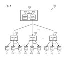
- FIG. 1 shows a wind park control system 100 .
- the wind park control system 100 as shown comprises a main control unit 110 , three sub control units 120 , 130 , 140 and a plurality of wind turbines 121 , 122 , 123 , 131 , 132 , 133 , 141 , 142 , 143 being assigned to the sub control units.
- the wind park control system 100 may be used for controlling a set point of an individual power output of each of the plurality of wind turbines 121 , 122 , 123 , 131 , 132 , 133 , 141 , 142 , 143 of the wind park.
- the main control unit 110 is adapted to determine a set point for a total power output of each group of wind turbines based on a reference set point for an overall power output of the wind park and on data being indicative for current characteristics of the wind park.
- the reference set point may be determined in a reference selector 111 .
- the reference selector 111 monitors grid conditions, and selects a reference that ensures the grid requirements are fulfilled for the entire group of turbines in the sub groups.
- the main control unit 110 is further adapted to distribute the determined set points between the sub control units 120 , 130 , 140 via main control signals being provided to the sub control units 120 , 130 , 140 from a control element 112 .
- Each main control signal is indicative for the set point for the total power output of the assigned group of wind turbines being controlled by the sub control units 120 , 130 , 140 .
- Each sub control unit 120 , 130 , 140 is adapted to determine a set point for an individual power output of each wind turbine 121 , 122 , 123 , 131 , 132 , 133 , 141 , 142 , 143 of the assigned group of wind turbines.
- Each sub control unit 120 , 130 , 140 is further adapted to distribute the determined set points between the wind turbines of the assigned group of wind turbines 121 , 122 , 123 , 131 , 132 , 133 , 141 , 142 , 143 via sub control signals being provided to each wind turbine of the assigned group of wind turbines.
- Each sub control signal is indicative for a set point for the individual power output of a wind turbine 121 , 122 , 123 , 131 , 132 , 133 , 141 , 142 , 143 .
- the described system may be used for controlling power or voltage/reactive power of multiple groups of wind turbines.
- Each group of turbines may have a functionality handling the communication to those turbines.
- the functionality (being provided by the sub control units, in the following also called applications) might also take over control during special network events such as frequency control.
- the communication to the individual turbines may take care of distributing power, voltage, and reactive power references to the turbines.
- voltage/reactive power control may mean that it controls one of those quantities at a time.
- the reference set point as mentioned throughout the description can be both a threshold and a value that has to be tracked.
- the reference is set to a ‘high value’ that means the park will produce as much as it can.
- the reference may typically be set to an upper limit that a transformer or a power cable is capable of handling.
- the reference is used actively to continuously control the current output of a wind park. When that is the case, the reference is a value that the main control unit should track.
- An overall control algorithm may be used for determining a total power output from the turbines. This total power output may be provided to the main control unit as reference set point. Then there are two levels of distribution.
- the main control unit may calculate how much power it wants from each of the participating group controllers (i.e., sub control units). Each participating group controller may distribute break down the number it receives from the main control unit to references sent to each turbine in its group.
- the main control unit wants 175 MW totally.
- the main control unit will send references to each participating group controller based on the current operating conditions of the group. For the sake of the example, the power reference ends up being 50, 50, 75 MW to each of the participating group controllers.
- the first group controller will then distribute the 50 MW to the turbines that it controls. The distribution is based on the turbines operating condition. If they all have identical operating conditions, then the reference to each turbine will end up being 50 MW/number of turbines.
- FIG. 2 shows a distribution of set points without site level control.
- the main control unit 110 provides a site level functionality that handles distribution of the overall reference 202 (being provided to the main control unit) to each of the groups the site is divided into.
- the main control unit does not get any measured inputs like active, reactive power, voltage or frequency and there is no site level closed loop control of power, voltage/reactive power in the main control unit.
- Each of the participating groups gets their own measured input signals 221 , 231 , 241 and performs their local closed loop control in the control elements 222 , 232 , 242 .
- the distribution function (distributing element 211 ) in the main control unit can handle a limitation for individual groups. An example could be that the transformer due to temperature or another operating condition can only handle 50 MW—then the power requested from that group of turbines may be limited to 50 MW.
- the Pdist 1 , Pdist 2 , PdistN in FIG. 2 (being sent from the main control unit to the sub control units) can be either active power and/or voltage/reactive power.
- the same main control unit can handle active power and voltage/reactive power or if desirable two main control units can be configured, one for handling active power, and one for handling voltage/reactive power.
- the main control unit gets input information about the actual topology of the wind park or other current characteristics of the wind park 201 .
- Each sub control unit comprises a distributing element 223 , 233 , 243 for distributing the individual control signals comprising the set point for the wind turbines Pref.
- This embodiment is simple. Further, there are no dynamics at the main control unit level, that needs to be tuned to address the latencies in the communication and control systems in the group controllers and in the turbines.
- the group controllers are identical to the controllers on single turbine group sites. However, disturbances or losses between the individual groups control points and the common grid interface might not be attenuated by the group controllers.
- the combined control actions of the individual groups might not add up to the reference given to the main control unit, i.e., if a group of turbines cannot produce the amount of power they claim to be able to produce then that “missing” power might not be requested from the remaining groups of turbines.
- the wind park control system 300 as shown in FIG. 3 is a two level control system.
- the control element 112 of the main control unit 110 comprises a closed loop control element 311 for ensuring that the combined output of all the turbines on the site matches the reference set point.
- the closed loop control element 311 may address both the dynamics response and the accuracy requested.
- the closed loop control may be performed based on received measurements 302 .
- the output of the control element 112 is distributed to the sub control units.
- the values distributed are calculated by the distribution function in the main control unit and the main control unit can handle the limitation for individual groups.
- An example could be that the transformer due to temperature or another operating condition can only handle 50 MW—then the power requested from that group of turbines will be limited to 50 MW.
- the main control unit can receive the necessary signals to perform the distribution from the individual sub control units.
- the signals shown in FIG. 3 are only meant as examples, so the distribution algorithm is in not limited to using those signals.
- each sub control unit comprises a control element 222 , 232 , 242 for performing a closed loop control.
- the Pdist 1 , Pdist 2 , PdistN in FIG. 3 can be either active power and/or voltage/reactive power.
- the same main control unit can handle active power and voltage/reactive power or if desirable two main control units can be configured one for handling active power, and one for handling voltage/reactive power.
- disturbances or losses between the individual groups control points and the common grid interface may be attenuated by the main control unit when the measurement is performed by a grid measurement unit.
- the main control unit ensures that the combined output of the turbine groups will match the reference set point with the desired accuracy when the measurement is performed by a grid measurement unit.
- the control loop performed by the sub control units can attenuate disturbances occurring within that group of turbines. Computational and communication loads are divided on multiple sub control units. However, in such a cascaded control, it might be required that the inner controller loop is much faster than the outer control loop.
- the dynamics of the turbines and the communication latency between the sub control units and the turbines may limit the reaction time of the inner controllers.
- All groups of wind turbines may be controlled by controllers, i.e., sub control units with the same or comparable control dynamics.
- the control functionality should not be divided into groups with fast or slow power control.
- the main control unit may ensure an error free control.
- FIG. 4 A further embodiment of the wind park control system 400 is shown in FIG. 4 .
- the main control unit may handle the site level control and may ensure that the combined output of the groups of turbines meet the reference set point with the required response time and accuracy.
- the idea of this embodiment is to treat each group of turbines as an aggregate turbine capable of producing the sum of the individual turbines.
- the output of the main control unit is distributed to the sub control units.
- the values distributed are calculated by the distribution function in the main control unit, which can handle limitation for individual groups.
- An example could be that the transformer due to temperature or another operating condition can only handle say 50 MW—then the power requested from that group of turbines will be limited to 50 MW.
- the measurement used by the control element of the main control unit 110 can either be performed by a grid measurement unit or the measurement can be calculated from measurements performed by the sub control units. If the Governor measurement in this embodiment is based on a calculation of reported signals from the sub control units, then the sub control units 120 , 130 , 140 may be allowed to take over control, when they detect a frequency event (over or under frequency event).
- the Pdist 1 , Pdist 2 , PdistN in FIG. 4 can be either active power and/or voltage/reactive power.
- the same main control unit can handle active power and voltage/reactive power or if desirable two main control units can be configured, one for handling active power, and one for handling voltage/reactive power.
- disturbances or losses between the individual groups control points and the common grid interface may be attenuated by the main control unit when the measurement is performed by a grid measurement unit.
- the main control unit may ensure that the combined output of the turbine groups matches the reference set point with the desired accuracy when the measurement is performed by a grid measurement unit.
- Computational and communication loads are divided on multiple sub control units. There is no need to handle controllers on multiple levels. If the measurement on park level is calculated based on reported data from the sub control units, it might be necessary to freeze the output of the main control unit and let the sub control units do their own closed loop control during frequency events.
Abstract
Description
Claims (10)
Applications Claiming Priority (3)
| Application Number | Priority Date | Filing Date | Title |
|---|---|---|---|
| EP12174100 | 2012-06-28 | ||
| EP12174100.3 | 2012-06-28 | ||
| EP12174100.3A EP2679812B1 (en) | 2012-06-28 | 2012-06-28 | Wind park control system |
Publications (2)
| Publication Number | Publication Date |
|---|---|
| US20140001763A1 US20140001763A1 (en) | 2014-01-02 |
| US9496812B2 true US9496812B2 (en) | 2016-11-15 |
Family
ID=46506181
Family Applications (1)
| Application Number | Title | Priority Date | Filing Date |
|---|---|---|---|
| US13/921,547 Active 2034-06-26 US9496812B2 (en) | 2012-06-28 | 2013-06-19 | Wind park control system |
Country Status (6)
| Country | Link |
|---|---|
| US (1) | US9496812B2 (en) |
| EP (1) | EP2679812B1 (en) |
| CN (1) | CN103527406B (en) |
| CA (1) | CA2820473A1 (en) |
| DK (1) | DK2679812T3 (en) |
| PL (1) | PL2679812T3 (en) |
Cited By (4)
| Publication number | Priority date | Publication date | Assignee | Title |
|---|---|---|---|---|
| US20150263521A1 (en) * | 2012-10-08 | 2015-09-17 | Vestas Wind Systems A/S | Line impedance compensation system |
| US10570882B2 (en) | 2017-11-13 | 2020-02-25 | General Electric Company | Dynamic active and reactive power capability for wind farms |
| US11067060B2 (en) | 2019-02-27 | 2021-07-20 | General Electric Company | System and method for controlling a hybrid energy facility having multiple power sources |
| US11133679B2 (en) | 2019-02-27 | 2021-09-28 | General Electric Company | System and method for operating a hybrid energy facility having multiple power sources |
Families Citing this family (10)
| Publication number | Priority date | Publication date | Assignee | Title |
|---|---|---|---|---|
| US9822766B2 (en) * | 2014-02-03 | 2017-11-21 | General Electric Company | Method for operating a wind farm and wind farm |
| ES2847901T3 (en) * | 2014-02-06 | 2021-08-04 | Ge Renewable Tech Wind Bv | Operating procedures for a set of wind turbines and systems |
| JP6342203B2 (en) * | 2014-04-03 | 2018-06-13 | 株式会社東芝 | Wind farm output control device, method, and program |
| US10041476B2 (en) * | 2014-09-02 | 2018-08-07 | Siemens Industry, Inc. | Systems, methods and apparatus for improved energy management systems with security-oriented probabilistic wind power generation dispatch |
| CN105159219A (en) * | 2015-09-09 | 2015-12-16 | 佛山市鸿源利电子科技有限公司 | Centralized control system for industrial microwave power source |
| CN108138749B (en) * | 2015-09-29 | 2020-10-16 | 维斯塔斯风力系统集团公司 | Reinforcement and regulation group for wind power plants |
| CN108808725B (en) * | 2017-05-05 | 2023-03-21 | 通用电气公司 | System and method for reactive power control of wind farm |
| DE102017115154A1 (en) * | 2017-07-06 | 2019-01-10 | Wobben Properties Gmbh | Wind farm controller and method for providing data and wind turbine and method for receiving data |
| US10763674B2 (en) | 2017-09-29 | 2020-09-01 | General Electric Company | System and method for controlling cluster-based wind farms |
| WO2020098893A1 (en) | 2018-11-16 | 2020-05-22 | Vestas Wind Systems A/S | Monitoring operation of a wind turbine |
Citations (8)
| Publication number | Priority date | Publication date | Assignee | Title |
|---|---|---|---|---|
| US20100025994A1 (en) | 2008-07-29 | 2010-02-04 | General Electric Company | Intra-area master reactive controller for tightly coupled windfarms |
| US7840312B2 (en) | 2004-12-17 | 2010-11-23 | Repower Systems Ag | Power control of a wind farm and method thereof |
| US20100332042A1 (en) * | 2009-06-26 | 2010-12-30 | Repower Systems Ag | Wind farm and method for controlling a wind farm |
| US20110112697A1 (en) * | 2007-12-14 | 2011-05-12 | Mitsubishi Heavy Industries, Ltd. | Wind turbine generator system and operation control method therefor |
| US20110166717A1 (en) * | 2010-05-28 | 2011-07-07 | Mitsubishi Heavy Industries, Ltd. | Real power control in wind farm |
| US20120010756A1 (en) | 2008-10-09 | 2012-01-12 | General Electric Company | Voltage control at windfarms |
| US20120066604A1 (en) * | 2011-04-29 | 2012-03-15 | General Electric Company | Method, system and computer program product for dynamic rule engine for a wind turbine farm |
| US20120101643A1 (en) * | 2011-12-28 | 2012-04-26 | Andreas Kirchner | Reactive power controller for controlling reactive power in a wind farm |
-
2012
- 2012-06-28 DK DK12174100.3T patent/DK2679812T3/en active
- 2012-06-28 PL PL12174100T patent/PL2679812T3/en unknown
- 2012-06-28 EP EP12174100.3A patent/EP2679812B1/en active Active
-
2013
- 2013-06-19 US US13/921,547 patent/US9496812B2/en active Active
- 2013-06-26 CA CA2820473A patent/CA2820473A1/en not_active Abandoned
- 2013-06-28 CN CN201310265176.5A patent/CN103527406B/en not_active Expired - Fee Related
Patent Citations (10)
| Publication number | Priority date | Publication date | Assignee | Title |
|---|---|---|---|---|
| US7840312B2 (en) | 2004-12-17 | 2010-11-23 | Repower Systems Ag | Power control of a wind farm and method thereof |
| EP1831981B1 (en) | 2004-12-17 | 2012-02-01 | REpower Systems AG | Power control of a wind farm and method therefor |
| US20110112697A1 (en) * | 2007-12-14 | 2011-05-12 | Mitsubishi Heavy Industries, Ltd. | Wind turbine generator system and operation control method therefor |
| US20100025994A1 (en) | 2008-07-29 | 2010-02-04 | General Electric Company | Intra-area master reactive controller for tightly coupled windfarms |
| US20120010756A1 (en) | 2008-10-09 | 2012-01-12 | General Electric Company | Voltage control at windfarms |
| US20100332042A1 (en) * | 2009-06-26 | 2010-12-30 | Repower Systems Ag | Wind farm and method for controlling a wind farm |
| DE102009030725A1 (en) | 2009-06-26 | 2010-12-30 | Repower Systems Ag | Wind farm and method for controlling a wind farm |
| US20110166717A1 (en) * | 2010-05-28 | 2011-07-07 | Mitsubishi Heavy Industries, Ltd. | Real power control in wind farm |
| US20120066604A1 (en) * | 2011-04-29 | 2012-03-15 | General Electric Company | Method, system and computer program product for dynamic rule engine for a wind turbine farm |
| US20120101643A1 (en) * | 2011-12-28 | 2012-04-26 | Andreas Kirchner | Reactive power controller for controlling reactive power in a wind farm |
Cited By (5)
| Publication number | Priority date | Publication date | Assignee | Title |
|---|---|---|---|---|
| US20150263521A1 (en) * | 2012-10-08 | 2015-09-17 | Vestas Wind Systems A/S | Line impedance compensation system |
| US9859710B2 (en) * | 2012-10-08 | 2018-01-02 | Vestas Wind Systems A/S | Line impedance compensation system |
| US10570882B2 (en) | 2017-11-13 | 2020-02-25 | General Electric Company | Dynamic active and reactive power capability for wind farms |
| US11067060B2 (en) | 2019-02-27 | 2021-07-20 | General Electric Company | System and method for controlling a hybrid energy facility having multiple power sources |
| US11133679B2 (en) | 2019-02-27 | 2021-09-28 | General Electric Company | System and method for operating a hybrid energy facility having multiple power sources |
Also Published As
| Publication number | Publication date |
|---|---|
| CN103527406A (en) | 2014-01-22 |
| EP2679812A1 (en) | 2014-01-01 |
| CA2820473A1 (en) | 2013-12-28 |
| US20140001763A1 (en) | 2014-01-02 |
| PL2679812T3 (en) | 2015-06-30 |
| CN103527406B (en) | 2018-04-24 |
| DK2679812T3 (en) | 2015-02-02 |
| EP2679812B1 (en) | 2014-12-31 |
Similar Documents
| Publication | Publication Date | Title |
|---|---|---|
| US9496812B2 (en) | Wind park control system | |
| DK2693589T3 (en) | wind park control system | |
| US8897922B2 (en) | Wind farm power control based on matrix reflecting a power load distribution between individual wind turbines | |
| KR101398400B1 (en) | Time-variant droop based inertial control method for wind power plant | |
| Liu et al. | A variable droop frequency control strategy for wind farms that considers optimal rotor kinetic energy | |
| DK2863513T3 (en) | Compensation of frequency fluctuations in networks with high turbine penetration | |
| CN111727537A (en) | Method of controlling wind turbine generator | |
| CN110445170A (en) | A kind of active power and frequency control method and system of the soft direct join net of marine wind electric field | |
| JP2011127461A (en) | Wind turbine generator system, wind turbine generator control device, and wind turbine generator control method | |
| JP2012120424A (en) | Enhanced plant level support of grid reconstruction | |
| JP2017175908A (en) | Power generation control device and control method | |
| US20180283354A1 (en) | Fast reacting control system for wind turbine | |
| JP5325348B1 (en) | Windmill control device and method, and wind power generation system | |
| CN110445171A (en) | A kind of active power and frequency control method and system based on the soft lineal system of marine wind electric field | |
| JP5388769B2 (en) | Wind power generation system, control method, control device, and program | |
| KR101475486B1 (en) | Control system for wind farm | |
| JP2015173570A (en) | Automatic frequency controller and automatic frequency control method | |
| US10416620B2 (en) | Method and control device for robust optimization of an electricity grid | |
| CN115940148A (en) | Minimum inertia requirement evaluation method and device, electronic equipment and storage medium | |
| US20230006443A1 (en) | Active power control in renewable power plants for grid stabilisation | |
| KR101705663B1 (en) | Microgrid control system and method for the same | |
| CN114330865A (en) | Power grid reserve capacity prediction method and system, computer equipment and storage medium | |
| CN115735310A (en) | Method and control system for voltage control of a renewable energy generator | |
| US10107263B2 (en) | Method of managing computing tasks in a wind farm | |
| JP2016214036A (en) | Control system, distribution method, and program |
Legal Events
| Date | Code | Title | Description |
|---|---|---|---|
| AS | Assignment |
Owner name: SIEMENS AKTIENGESELLSCHAFT, GERMANY Free format text: ASSIGNMENT OF ASSIGNORS INTEREST;ASSIGNOR:SIEMENS WIND POWER A/S;REEL/FRAME:030815/0272 Effective date: 20130701 Owner name: SIEMENS WIND POWER A/S, DENMARK Free format text: ASSIGNMENT OF ASSIGNORS INTEREST;ASSIGNORS:KRAGELUND, MARTIN NYGAARD;NIELSEN, JOERGEN NYGAARD;PASMA, TJIP;AND OTHERS;REEL/FRAME:030815/0254 Effective date: 20130626 |
|
| STCF | Information on status: patent grant |
Free format text: PATENTED CASE |
|
| AS | Assignment |
Owner name: SIEMENS GAMESA RENEWABLE ENERGY A/S, DENMARK Free format text: ASSIGNMENT OF ASSIGNORS INTEREST;ASSIGNOR:SIEMENS AKTIENGESELLSCHAFT;REEL/FRAME:048003/0631 Effective date: 20181025 |
|
| MAFP | Maintenance fee payment |
Free format text: PAYMENT OF MAINTENANCE FEE, 4TH YEAR, LARGE ENTITY (ORIGINAL EVENT CODE: M1551); ENTITY STATUS OF PATENT OWNER: LARGE ENTITY Year of fee payment: 4 |