WO2016181476A1 - 画像処理装置、画像処理方法及び画像処理プログラム - Google Patents
画像処理装置、画像処理方法及び画像処理プログラム Download PDFInfo
- Publication number
- WO2016181476A1 WO2016181476A1 PCT/JP2015/063540 JP2015063540W WO2016181476A1 WO 2016181476 A1 WO2016181476 A1 WO 2016181476A1 JP 2015063540 W JP2015063540 W JP 2015063540W WO 2016181476 A1 WO2016181476 A1 WO 2016181476A1
- Authority
- WO
- WIPO (PCT)
- Prior art keywords
- pixel
- sum
- color space
- pixel values
- pixels arranged
- Prior art date
- Legal status (The legal status is an assumption and is not a legal conclusion. Google has not performed a legal analysis and makes no representation as to the accuracy of the status listed.)
- Ceased
Links
Images







Classifications
-
- H—ELECTRICITY
- H04—ELECTRIC COMMUNICATION TECHNIQUE
- H04N—PICTORIAL COMMUNICATION, e.g. TELEVISION
- H04N25/00—Circuitry of solid-state image sensors [SSIS]; Control thereof
- H04N25/60—Noise processing, e.g. detecting, correcting, reducing or removing noise
- H04N25/61—Noise processing, e.g. detecting, correcting, reducing or removing noise the noise originating only from the lens unit, e.g. flare, shading, vignetting or "cos4"
- H04N25/611—Correction of chromatic aberration
-
- H—ELECTRICITY
- H04—ELECTRIC COMMUNICATION TECHNIQUE
- H04N—PICTORIAL COMMUNICATION, e.g. TELEVISION
- H04N25/00—Circuitry of solid-state image sensors [SSIS]; Control thereof
- H04N25/10—Circuitry of solid-state image sensors [SSIS]; Control thereof for transforming different wavelengths into image signals
- H04N25/11—Arrangement of colour filter arrays [CFA]; Filter mosaics
- H04N25/13—Arrangement of colour filter arrays [CFA]; Filter mosaics characterised by the spectral characteristics of the filter elements
- H04N25/134—Arrangement of colour filter arrays [CFA]; Filter mosaics characterised by the spectral characteristics of the filter elements based on three different wavelength filter elements
-
- H—ELECTRICITY
- H04—ELECTRIC COMMUNICATION TECHNIQUE
- H04N—PICTORIAL COMMUNICATION, e.g. TELEVISION
- H04N9/00—Details of colour television systems
- H04N9/64—Circuits for processing colour signals
- H04N9/646—Circuits for processing colour signals for image enhancement, e.g. vertical detail restoration, cross-colour elimination, contour correction, chrominance trapping filters
Definitions
- the present invention relates to an image processing apparatus, an image processing method, and an image processing program.
- axial chromatic aberration occurs in an image taken through a normal optical system.
- the longitudinal chromatic aberration refers to a false color that is caused by the optical system, the imaging system, and the image processing system, and is caused by the focal position on the optical axis being different depending on the wavelength, that is, a color that does not occur in the original subject.
- amending such axial chromatic aberration by image processing is proposed (for example, refer patent document 1).
- Patent Document 1 for a target pixel in image data, as a parameter indicating the possibility of false color, closeness to whiteout, saturation magnitude, and closeness to a specific hue are evaluated, and at least one of these Is applied to correct axial chromatic aberration.
- the present invention has been made in view of the above-described circumstances, and an object thereof is to accurately correct axial chromatic aberration based on human visual characteristics.
- One embodiment of the present invention provides a sum total of pixel values of pixels arranged in one direction and the other direction across each pixel of interest for a plurality of pixels arranged in a line including the pixel of interest in the input image. Based on at least one of a pixel value calculation unit and a calculation result by the total pixel value calculation unit or a pixel value of the target pixel, it is determined whether or not the target pixel is an origin of axial chromatic aberration.
- a generation starting point detection unit that detects a pixel, a region determination unit that determines a predetermined peripheral region centered on the target pixel detected as the generation starting point as an axial chromatic aberration region, and a target pixel detected as the generation starting point.
- the color space information calculation unit that calculates the color space information on the specific color space for the one direction and the other direction, respectively, and the color space information calculation unit
- the A color space difference calculation unit that calculates a difference between the color space information in the one direction and the color space information in the other direction, and a correction amount for the axial chromatic aberration correction according to the difference calculated by the color space difference calculation unit.
- the image processing apparatus includes a correction amount calculation unit that calculates the correction amount and a correction unit that corrects the axial chromatic aberration region using the correction amount.
- the sum of the pixel values of the pixels arranged on a straight line on both sides of the target pixel is calculated by the total pixel value calculation unit, and the generation start point is detected based on the calculation result or the pixel value of the target pixel.
- the unit determines whether the pixel of interest is an origin of axial chromatic aberration, and detects the origin.
- the color space information calculation unit calculates the color space information in the specific color space for the pixel of interest in one direction and the other direction, respectively. These differences are calculated by the calculation unit.
- correction processing is performed on the axial chromatic aberration region including the peripheral region centered on the target pixel.
- on-axis chromatic aberration is calculated based on human visual characteristics by calculating the correction amount that evaluates not only the target pixel but also the pixel values of pixels arranged on both sides of the target pixel in a straight line. Correction can be performed.
- the color space information calculation unit calculates at least one of information on the color angle, information on the intensity of the color, and information on the brightness of the color as the color space information on the specific color space
- the color space difference calculation unit as a difference between the color space information in one direction and the color space information in the other direction, based on a calculation result by the color space information calculation unit, At least one of the intensity difference and the color brightness difference is calculated, and the correction amount calculation unit calculates the correction amount for the axial chromatic aberration correction based on the calculation result by the color space difference calculation unit. It is good to do. This makes it possible to calculate the optimal correction amount according to the color angle difference, color intensity difference, and brightness difference between adjacent areas where humans easily perceive axial chromatic aberration due to their visual characteristics. can do.
- the correction amount calculation unit may calculate a larger correction amount as the color angle difference is closer to 180 degrees, and may calculate a smaller correction amount as the distance from the 180 degrees is increased. In this way, when the angle of the color space is expressed from 0 degrees to 360 degrees as in the hue circle, coloration is visually detected by humans, such as 180 degrees where the two colors are counter electrodes. When it is easy, an appropriate correction amount can be calculated.
- the correction amount calculation unit may calculate a larger correction amount as the absolute value of the color intensity difference is larger, and may calculate a smaller correction amount as the absolute value is smaller. By doing so, it is possible to calculate an appropriate correction amount when there is a large difference in color intensity and it is easy for humans to visually detect coloring.
- the correction amount calculation unit may calculate a larger correction amount as the absolute value of the color brightness difference is larger, and may calculate a smaller correction amount as the absolute value is smaller. By doing so, an appropriate correction amount can be calculated even when the difference in color brightness is large and it is easy for humans to visually detect coloring.
- the correction amount calculation unit may calculate a correction amount in which the color angle is the same in the one direction and the other direction. By doing so, there is no difference in the color angle after correction, and it is possible to calculate a desired correction amount for human coloring.
- the correction amount calculation unit may calculate a correction amount in which the intensity of the color is the same in the one direction and the other direction. By doing so, there is no difference in color intensity after correction, and it is possible to calculate a desirable correction amount for human coloring.
- the correction amount calculation unit may calculate a correction amount in which the brightness of the color is the same in the one direction and the other direction. By doing so, there is no difference in color brightness after correction, and it is possible to calculate a desired correction amount for human coloring.
- the specific color space may be an HSV space.
- the specific color space may be an L * a * b * space. In this way, it is possible to calculate a color space that is close to the human visual sense.
- the pixel value of the said attention pixel is larger than a predetermined threshold value, or the pixel arranged in the said one direction calculated by the said total pixel value calculation part in the said aspect
- the magnitude relationship between the sum of the G pixel values and the sum of the R pixel values is opposite to the magnitude relationship between the sum of the G pixel values and the sum of the R pixel values of the pixels arranged in the other direction.
- the magnitude relationship between the sum of the G pixel values of the pixels arranged in the one direction and the sum of the B pixel values is the sum of the G pixel values of the pixels arranged in the other direction.
- the pixel of interest may be detected as a starting point of axial chromatic aberration when the magnitude relationship between the pixel value and the sum of the pixel values of B is opposite. By doing so, at least one of the near-saturated region and the region other than the near-saturated region can be detected as a starting point of axial chromatic aberration.
- Pg D1 is the sum of G pixel values of pixels arranged in the one direction from the target pixel
- Pg D2 is the sum of G pixel values of pixels arranged in the other direction from the target pixel
- Pb D1 is the sum of B pixel values of pixels arranged in the one direction from the target pixel
- Pb D2 is the sum of B pixel values of pixels arranged in the other direction from the target pixel.
- Pg D1 Pr D1 Pg D2 ⁇ Pr D2 Pg D2 ⁇ Pb D2
- Pg D1 is the sum of G pixel values of pixels arranged in the one direction from the target pixel
- Pg D2 is the sum of G pixel values of pixels arranged in the other direction from the target pixel.
- Pr D1 is the sum of R pixel values of the pixels arranged in the one direction from the target pixel
- Pr D2 is the sum of R pixel values of the pixels arranged in the other direction from the target pixel
- Pb D2 is the sum of the B pixel values of the pixels arranged in the other direction from the target pixel.
- Pr D2 is a sum of R pixel values of pixels arranged in the other direction from the target pixel
- Pb D1 is a sum of pixel values of B of pixels arranged in the one direction from the target pixel
- Pb D2 is the sum of the B pixel values of the pixels arranged in the other direction from the target pixel.
- This also causes purple fringes in the other direction, and the sum of the B pixel values in one direction is smaller than the sum of the G pixel values and becomes a color close to the opposite color in the hue circle. Can be detected as a starting point of axial chromatic aberration.
- Pr D1 is the sum of R pixel values of the pixels arranged in the one direction from the target pixel
- Pr D2 is the sum of R pixel values of the pixels arranged in the other direction from the target pixel
- Pb D1 is the sum of the B pixel values of the pixels arranged in the one direction from the target pixel.
- green fringe occurs in one direction, the sum of R pixel values in the other direction is larger than the sum of G pixel values, and the color circle is close to the opposite color, and the green fringe is conspicuous.
- the location can be detected as a starting point of axial chromatic aberration.
- Pr D1 is the sum of R pixel values of pixels arranged in one direction from the target pixel
- Pb D1 is the sum of B pixel values of pixels arranged in the one direction from the target pixel
- Pb D2 is the sum of the B pixel values of the pixels arranged in the other direction from the target pixel.
- a conspicuous place can be detected as the origin of axial chromatic aberration.
- Pg D1 is the sum of G pixel values of pixels arranged in the one direction from the target pixel
- Pg D2 is the sum of G pixel values of pixels arranged in the other direction from the target pixel.
- Pr D1 is the sum of R pixel values of the pixels arranged in the one direction from the target pixel
- Pr D2 is the sum of R pixel values of the pixels arranged in the other direction from the target pixel
- Pb D1 is the sum of the B pixel values of the pixels arranged in the one direction from the target pixel
- Pb D2 is the sum of the B pixel values of the pixels arranged in the other direction from the target pixel
- TH R1 , TH R2 , TH B1 , and TH B2 are arbitrary constants. In this way, by appropriately selecting TH R1 , TH R2 , TH B1 , and TH B2 , it is possible to reduce the influence of noise and stably detect the origin of axial chromatic aberration.
- Pg D1 is the sum of G pixel values of pixels arranged in the one direction from the target pixel
- Pg D2 is the sum of G pixel values of pixels arranged in the other direction from the target pixel.
- Pr D1 is the sum of R pixel values of the pixels arranged in the one direction from the target pixel
- Pr D2 is the sum of R pixel values of the pixels arranged in the other direction from the target pixel
- Pb D1 is the sum of the B pixel values of the pixels arranged in the one direction from the target pixel
- Pb D2 is the sum of the B pixel values of the pixels arranged in the other direction from the target pixel
- TH R , TH B is an arbitrary constant.
- Pr D1 is the sum of R pixel values of the pixels arranged in the one direction from the target pixel
- Pr D2 is the sum of R pixel values of the pixels arranged in the other direction from the target pixel
- Pb D1 is the sum of the B pixel values of the pixels arranged in the one direction from the target pixel
- Pb D2 is the sum of the B pixel values of the pixels arranged in the other direction from the target pixel
- K R , K B is an arbitrary constant.
- the said image may have a pixel value of all RGB in each pixel.
- the image may have a pixel value in which at least one pixel value of RGB is missing in each pixel.
- pixel values of pixels arranged in one direction and other directions across the target pixel for each of a plurality of pixels arranged in a line including the target pixel in the input image are respectively provided for each color.
- a region determination step for determining a predetermined peripheral region centered on the target pixel detected as the generation start point as an axial chromatic aberration region, and the total pixel value calculation step for the target pixel detected as the generation start point
- the color space information calculating step as the color space information on the specific color space, at least one of information on the color angle, information on the intensity of the color, and information on the brightness of the color is calculated.
- the color space difference calculation step based on the calculation result in the color space information calculation step, the difference between the color angle information as the difference between the color space information in the one direction and the color space information in the other direction, At least one of a difference in color intensity and a difference in brightness of the color is calculated, and in the correction amount calculation step, a correction amount for axial chromatic aberration correction is calculated based on a calculation result in the color space difference calculation step. It may be calculated.
- the generation start point detection step when the pixel value of the target pixel is larger than a predetermined threshold value, or arranged in the one direction calculated by the total pixel value calculation unit
- the magnitude relationship between the sum of the G pixel values of the pixels and the sum of the R pixel values is opposite to the magnitude relationship between the sum of the G pixel values of the pixels arranged in the other direction and the sum of the R pixel values.
- the magnitude relationship between the sum of the G pixel values of the pixels arranged in the one direction and the sum of the B pixel values of the G pixels of the pixels arranged in the other direction is
- the pixel of interest may be detected as a starting point of axial chromatic aberration.
- pixel values of pixels arranged in one direction and other directions across the target pixel for each of a plurality of pixels arranged in a line including the target pixel in the input image are respectively provided for each color.
- a region determination step for determining a predetermined peripheral region centered on the target pixel detected as the generation start point as an axial chromatic aberration region, and the total pixel value calculation step for the target pixel detected as the generation start point
- the computer uses at least one of information on the color angle, information on the intensity of the color, and information on the brightness of the color as the color space information on the specific color space.
- the color angle is calculated as a difference between the color space information in the one direction and the color space information in the other direction based on the calculation result of the color space information calculation step.
- the axial chromatic aberration correction is performed based on the calculation result of the color space difference calculation step. The correction amount may be calculated.
- the generation start point detecting step when the pixel value of the target pixel is larger than a predetermined threshold, or in the one direction calculated by the total pixel value calculation unit
- the magnitude relationship between the sum of the G pixel values of the arranged pixels and the sum of the R pixel values is such that the sum of the G pixel values of the pixels arranged in the other direction and the sum of the R pixel values.
- the magnitude relationship is opposite to the magnitude relation, or the magnitude relation between the sum of the G pixel values of the pixels arranged in the one direction and the sum of the B pixel values is G of the pixels arranged in the other direction.
- the pixel of interest may be detected as a starting point of axial chromatic aberration when the magnitude relationship between the sum of the pixel values of B and the sum of the pixel values of B is opposite.
- axial chromatic aberration can be detected and corrected based on human visual characteristics in at least one of the near-saturated region or the region other than the near-saturated region.
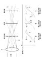
- FIG. 1 is a block diagram illustrating an image processing apparatus according to an embodiment of the present invention. It is a figure which shows typically the relationship between the optical system to which the image processing apparatus of FIG. 1 is applied, and axial chromatic aberration. It is a figure which shows typically the relationship between the optical system to which the image processing apparatus of FIG. 1 is applied, and axial chromatic aberration.
- 2 is a flowchart illustrating an image processing method using the image processing apparatus of FIG. 1. It is a figure which shows the coordinate relationship of the attention pixel set in the image processing apparatus of FIG. 1, and its peripheral pixel. It is a figure which shows the coordinate relationship of the attention pixel set in the image processing apparatus of FIG.
- FIG. 2 is a diagram illustrating a coordinate relationship between a target pixel set in the image processing apparatus of FIG. 1 and its surrounding pixels, and in particular, a target pixel before correction when the pixel position of the target pixel is determined as a D1 direction and the pixel The coordinate relationship with surrounding pixels is shown.
- FIG. 2 is a diagram illustrating a coordinate relationship between a target pixel set in the image processing apparatus of FIG.
- the image processing apparatus performs image processing to be described later on an input image acquired by a camera.
- the input image that is the processing target of the image processing apparatus 1 is converted into an electrical signal in the solid-state imaging device after the light beam that has entered through the imaging optical system (not shown) is subjected to fixed noise pattern removal, analog gain adjustment, and the like.
- the image signal is converted into a digital signal by an A / D converter and subjected to various image processing.
- This input image is a full-color image in which all RGB signal values are obtained at each pixel, and a three-plate color image acquired by a three-plate image sensor or a single-plate color image acquired by a single-plate image sensor at each pixel. It is an image that has been interpolated to obtain RGB values.
- the image processing apparatus includes an area extraction unit 2 that extracts an axial chromatic aberration region in which an axial chromatic aberration occurs in an input image, and an axis extracted by the region extraction unit 2.
- An axial chromatic aberration correction amount calculation unit 3 that calculates a correction amount for the upper chromatic aberration region and an aberration correction unit 4 that outputs an output image in which the axial chromatic aberration in the axial chromatic aberration region is corrected are provided.
- the region extraction unit 2 includes a total pixel value calculation unit 10, a generation start point detection unit 11, and a region determination unit 12.
- the total pixel value calculation unit 10 sets a target pixel in the input image, and for a plurality of pixels arranged in a line including the set target pixel, the one direction (D1) and the other direction centering on the target pixel
- the pixel values of the pixels arranged in (D2) are summed for each color.
- the occurrence starting point detection unit 11 includes at least a pixel value of the target pixel, or a total pixel value of pixels arranged in one direction across the target pixel calculated by the total pixel value calculation unit 11 or a total pixel value of pixels arranged in the other direction. On the basis of one of them, it is determined whether the pixel of interest is the origin of axial chromatic aberration, and the pixel of interest that is the origin of occurrence is detected.
- the generation start point of the longitudinal chromatic aberration detected by the generation start point detection unit 5 is, for example, a target pixel in which the magnitude of the G pixel value of the target pixel becomes a saturation level, or as shown in FIG.
- a long wavelength R with respect to G forms an image on the far side in the optical axis direction
- a short wavelength B with respect to G forms an image on the near side in the optical axis direction.
- This RGB imaging position shift appears as axial chromatic aberration.
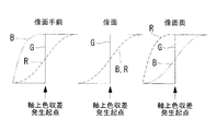
- G When an achromatic step edge is photographed, G has a step edge shape on the image plane, but R and B do not form an image and the step edge shape is dull.
- G In the back of the image plane, G does not form an image, so the shape of the step edge is dull, but R forms an image and maintains the shape of the step edge.
- B is duller than G.
- G In front of the image plane, G does not form an image, so the shape of the step edge is dull, and B forms an image and maintains the shape of the step edge.
- R has a shape duller than G.
- the region determination unit 12 determines a predetermined peripheral region of the target pixel that is the generation start point detected by the generation start point detection unit 5 as an axial chromatic aberration region. That is, when the pixel of interest is detected as the origin of axial chromatic aberration, the pixel is subject to correction of axial chromatic aberration. Therefore, the region consisting of the pixel of interest and a predetermined peripheral pixel centered on the pixel of interest is the axial chromatic aberration region.
- the axial chromatic aberration region can be set as appropriate, for example, a 5 ⁇ 5 pixel region centered on the pixel of interest or a 7 ⁇ 7 pixel region.
- the axial chromatic aberration correction amount calculation unit 3 includes a color space information calculation unit 15, a color space difference calculation unit 16, and a correction amount calculation unit 17.
- the color space information calculation unit 15 calculates the color space information on the specific color space for the target pixel detected as the generation start point by the generation start point detection unit 5 for each of the one direction and the other direction with respect to the target pixel.
- the specific color space for example, HSV space or l * a * b space can be applied.
- the color space information is the sum of pixel values for each color for pixels arranged in one direction (D1) and the other direction (D2) around the target pixel, calculated by the total pixel value calculation unit 10. Calculate based on
- the color space difference calculation unit 16 calculates a difference between the color space information in one direction calculated by the color space information calculation unit 15 and the color space information in the other direction.
- the correction amount calculation unit 17 calculates a correction amount for the axial chromatic aberration region according to the difference calculated by the color space difference calculation unit 16.
- the aberration correction unit 4 corrects the axial chromatic aberration region using the correction amount calculated by the correction amount calculation unit 17.
- step S1 the total pixel value calculation unit 10 sets a target pixel (0, 0) in the input image as shown in FIG. 5, and in the next step S2 (total pixel value calculation step), the target pixel 5, the sum of pixel values of a plurality of pixels arranged on both sides of the pixel of interest is calculated in each of the four directions of the vertical direction, the horizontal direction, the right diagonal direction, and the left diagonal direction in FIG. 5 (step S2). Specifically, the sum of pixel values for each color in each direction is calculated according to the equation shown in Equation 1.
- P c (x, y) is the pixel value of the pixel located at the coordinates (x, y)
- P cL is the sum of the pixel values of the pixel column on the left side of the target pixel
- P cR is the right side of the target pixel.
- the total pixel value of the pixel column P cT is the total pixel value of the upper pixel column of the target pixel
- P cB is the total pixel value of the lower pixel column of the target pixel
- P cLT is the upper left side of the target pixel.
- P cLB is the total pixel value of the pixel column on the lower left side of the target pixel
- P cRT is the total pixel value of the pixel column on the upper right side of the target pixel
- P cRB is the lower right side of the target pixel This is the sum of the pixel values of the side pixel column.
- the subscript c means color and can be replaced with r, g, and b, and the total of pixel values for each color is calculated by replacement. I and m are positive integers.
- step S3 occurrence start point detection step
- the occurrence start point detection unit 11 determines that the following conditional expression (1) or the sum of the pixel values calculated by the total pixel value calculation part 10 is conditional expressions (2) to (5).
- conditional expression (1) indicates that when the magnitude of the G pixel value of the pixel of interest is larger than an arbitrary saturation level threshold THsat, the pixel of interest is detected as an origin of axial chromatic aberration.
- Pg D1 is the sum of G pixel values of pixels arranged in one direction D1 from the target pixel
- Pg D2 is the sum of G pixel values of pixels arranged in the other direction D2 from the target pixel
- Pr D1 is the sum of R pixel values of pixels arranged in one direction D1 from the target pixel
- Pr D2 is the sum of R pixel values of pixels arranged in the other direction D2 from the target pixel
- Pb D1 is the target pixel
- Pb D2 is the total of the B pixel values of the pixels arranged in the other direction D2 from the target pixel.
- the subscript D1 indicates one direction from the target pixel, and for example, L, T, LT, and LB in Equation 1 are applicable. Further, the subscript D2 indicates the other direction from the target pixel, and for example, R, B, RT, and RB are applicable. The definition of the direction is arbitrary, but when L, T, LT, and LB are selected as D1, D2 becomes R, B, RT, and RB.
- conditional expression (1) when comparing the target pixel with the arbitrary saturation level threshold THsat, only the G pixel of the target pixel is used.
- the saturation level threshold value and the luminance value can be compared, and other known methods can be used.
- the method for calculating the origin of axial chromatic aberration in a region other than near-saturation is not limited to the above example, and a known method can be used.
- step S4 detection information generation step
- the generation start point detection unit 11 sets “0” for the pixel of interest detected as the generation start point of axial chromatic aberration, and “1” for the pixel detected as not the generation start point. Detection information to be generated.
- the generation start point detection unit 11 holds PrD1, PrD2, PgD1, PgD2, PbD1, and PbD2 corresponding to the pixel position.
- the four directions of the vertical direction, horizontal direction, right diagonal direction, and left diagonal direction in FIG. 5 are associated with the pixel position. Which direction satisfies the conditional expressions (2) to (5), and holds the one direction D1 and the other direction D2 with respect to that direction. That is, the occurrence start point detection unit 11 holds whether D1 is L, T, LT, or LB and D2 is R, B, RT, or RB as information related to the detection information. Keep it.
- step S ⁇ b> 5 region determination step
- the region determination unit 12 detects that the target pixel is the generation start point of axial chromatic aberration, that is, the detection information generated by the generation start point detection unit 11 for the target pixel is “ In the case of “0”, the region including the target pixel and the predetermined peripheral pixel is determined as the axial chromatic aberration region.
- the axial chromatic aberration region for example, a region including 7 ⁇ 7 pixels centered on a pixel whose detection information is “0” can be set as appropriate.
- step S6 color space information calculation step
- the color space information calculation unit 15 determines the color of the specific color space from PrD1, PgD1, PbD1 and PrD2, PgD2, PbD2 corresponding to the pixel position where the detection information is “0”. Calculate spatial information. For example, when the specific color space is HSV space, at least one of PrD1, PgD1, and PbD1 to PhD1, PsD1, and PvD1 is calculated, and PrD2, PgD2, and PbD2 to PhD2, PsD2, and PvD2 are calculated in the same color space information. To do.
- PhD1 and PhD2 indicate color space information regarding angles (hues) in the D1 direction and D2 direction of the target pixel detected as the generation start point
- PsD1 and PsD2 indicate the target detection detected as the generation start point.
- the color space information regarding the intensity (saturation) in the D1 direction and the D2 direction in the pixel is shown
- PvD1 and PvD2 are related to the brightness (brightness) in the D1 direction and the D2 direction in the target pixel detected as the generation start point. Indicates color space information.
- the specific color space is L * a * b * space
- at least one of PrD1, PgD1, PbD1 to Pl * D1, Pa * D1, Pb * D1, PrD2, PgD2, PbD2 to Pl * D2, Pa * The same color space information as the direction D1 of D2 and Pb * D2 is calculated.
- Pl * D1 and Pl * D2 indicate color space information regarding brightness (brightness) in the D1 direction and D2 direction at the target pixel detected as the generation start point
- Pa * D1, Pb * D1, Pa * D2 and Pb * D2 are information regarding complementary colors, and can be used as color space information regarding angle and intensity.
- step S7 color space difference calculation step
- the color space difference calculation unit 16 calculates a difference in color space from the color space information in two directions.
- the color section information calculation unit 16 calculates at least one of a color angle difference, a color intensity difference, and a brightness difference as a difference.
- step S8 correction amount calculation step
- a correction amount is calculated based on the difference calculated by the color space difference calculation unit 16.
- step S9 it is determined whether or not all pixels have been processed. If the process for the pixel is not completed, the process returns to step S1, and the process of steps S2 to S7 is repeated with the pixel that has not been processed yet as the target pixel.
- the correction amount calculated by the correction amount calculation unit 17 is used for the axial chromatic aberration region set by the region determination unit 12 in step S10 (aberration correction step).
- a correction process is performed by the aberration correction unit 4 and the process ends.
- At least one of an angle, an intensity, and a brightness is calculated as color space information, and at least one of an angle difference, an intensity difference, and a brightness difference is calculated from the color space information.
- a correction amount is calculated based on information obtained by combining any one or more of these differences, thereby correcting the axial chromatic aberration region.
- the correction amount is calculated by combining any one or more of the difference in angle, the difference in intensity, and the difference in brightness
- the color space angle information calculation unit 15 calculates the color space information related to the angles for the two directions (D1, D2) held as information related to the detection information by the generation start point detection unit 11 (step S6).
- the color space angle difference calculation unit 16 calculates the difference from the color space information regarding the calculated angle (step S7).
- the generation start point detection unit 11 determines that the target pixel is the generation start point by satisfying the conditional expression (1)
- the size of the G pixel value of the target pixel is greater than an arbitrary saturation level threshold THsat.
- the D1 and D2 in a specific direction are not determined.
- the Pangle is calculated for D1 and D2 in all four directions in the vertical, horizontal, and diagonal directions, and the value with the largest Pangle can be adopted.
- the correction amount calculation unit 17 calculates the correction amount Ca from the Pangle. For example, when the Pangle is a value from 0 to 360 degrees, the correction amount Ca is increased as the Pangle is closer to 180 degrees, and the correction amount is decreased as the Pangle is farther from 180 degrees.
- the angle of the color space is expressed from 0 degrees to 360 degrees as in a hue circle, an appropriate correction amount when coloration is easy to be detected by humans, such as 180 degrees where two colors are counter electrodes Can be calculated.
- the correction amount so that the color angle is the same in one direction and the other direction, there is no difference in the color angle after correction, and it is possible to calculate a desired correction amount for human coloring. .
- the correction processing of the aberration correction unit based on the correction amount calculated from the color space information regarding the angle for example, sets the pixel value before correction to Pr as shown in FIG. , Pg, Pb, and corrected pixel values as Pr ′, Pg ′, Pb ′ as shown in FIG. 7 are performed according to the following equations (8) to (10).
- Pr ' Pr-Ca (8)
- Pg ' Pg (9)
- Pb ' Pb-Ca (10)
- correction can be performed according to the following equation (11), where Pa is the angle of the pixel value before correction, and Pa ′ is the angle of the pixel value after correction.
- Pa ' Pa-Ca (11)
- the color space information calculation unit 15 calculates Pangle 1 and Pangle 2 as the color space information regarding the angle according to the following Expressions (12) and (13).
- Pangle1 PhD1 (12)
- Pangle2 PhD2 (13)
- Pangle 1 and Pangle 2 are calculated according to the following formulas (14) and (15) as the color space information regarding the angle.
- Pangle1 tan-1 (Pb * D1 / Pa * D1)
- Pangle2 tan-1 (Pb * D2 / Pa * D2)
- the color space information calculation unit 15 calculates, for example, Pangle 1 and Pangle 2 using D1 and D2 in all the four directions, ie, the vertical, horizontal, and diagonal directions, and the color space difference calculation unit 16
- the maximum absolute value of the difference between the two and the Pangle 2 is adopted as the difference of the color space information regarding the angle, and D1 and D2 indicating the maximum absolute value can be set as the specific direction.
- the absolute value Pangle of the difference in the color space information related to the angle is calculated by Expression (16).
- the correction amount calculation unit 17 calculates the correction amounts Ca1 and Ca2 from the Pangle, Pangle1, and Pangle2, for example, according to the following equations (17) to (20).
- Pangle1 is larger than Pangle2
- Ca1 Pangle (17)
- Ca2 0 (18)
- Ca2 Pangle (20)
- the aberration correction unit 4 performs correction processing on the axial chromatic aberration region using the correction amount based on the angle calculated by the correction amount calculation unit 17.
- the correction processing based on the angle by the aberration correction unit 4 uses Pr1, Pg1, Pb1 (FIG. 8) as pixel values before correction, and after correction.
- the pixel values can be expressed by the following equations (21) to (23) with Pr1 ′, Pg1 ′, and Pb1 ′ (FIG. 9).
- Pr1 ' Pr-Ca1 (21)
- Pg1 ' Pg (22)
- Pb1 ' Pb-Ca1 (23)
- correction processing can be performed by the following equation (28), where the angle of the pixel value before correction is Pangle 2 and the angle of the pixel value after correction is Pagle 2 ′.
- Pangle2 ' Pangle2-Ca2 (28)
- the color space angle information calculation unit 15 calculates the color space information related to the intensity for each of the two directions (D1, D2) held as information related to the detection information by the generation start point detection unit 11 (step S6).
- the color space angle difference calculation unit 16 calculates the difference from the color space information regarding the calculated intensity (step S7). Specifically, when the specific color space is an HSV space, PsD1 and PsD2 are calculated as color space information regarding intensity, and an absolute value Pstrength of these differences is calculated according to the following equation (29).
- Pstrength
- Pstrength
- the generation start point detection unit 11 determines that the target pixel is the generation start point by satisfying the conditional expression (1) and the D1 and D2 in the specific direction are not determined, for example, the above-described vertical, horizontal, and diagonal totals are used.
- Pstrength can be calculated from D1 and D2 in all four directions, the maximum value of Pstrength can be adopted, and D1 and D2 indicating the maximum value can be set as a specific direction.
- the correction amount calculation unit 17 calculates the correction amount Cb from Pstrength according to the following equation (31).
- K is an arbitrary constant.
- Cb K * Pstrength (31)
- the aberration correction unit 4 performs correction processing on the axial chromatic aberration region using the correction amount based on the intensity calculated by the correction amount calculation unit.
- correction processing can be performed according to the following equation (35), where Ps is the intensity of the pixel value before correction and Ps ′ is the intensity of the pixel value after correction.
- Ps' Ps-Cb (35)
- the color space information calculation unit 15 calculates Pstrength1 and Pstrength2 as the color space information regarding the intensity according to the following expressions (36) and (37).
- Pstrength1 PsD1 ... (36)
- Pstrength2 PsD2 (37)
- Pstrength1 and Pstrength2 are calculated according to the following equations (38) and (39) as the color space information regarding the intensity.
- Pstrength1 ⁇ (Pa * D1 ⁇ 2 + Pb * D1 ⁇ 2) (38)
- Pstrength2 ⁇ (Pa * D2 ⁇ 2 + Pb * D2 ⁇ 2)... (39)
- the color space information calculation unit 15 performs the above-described process.
- Pstrength1 and Pstrength2 are calculated from D1 and D2 in all four directions, vertical, horizontal, and diagonal, and the color space difference calculation unit 16 calculates the absolute value of the difference between Pstrength1 and Pstrength2 in the color space information regarding the intensity Adopted as a difference, D1 and D2 indicating the maximum absolute value can be set as a specific direction.
- the absolute value Pstrength of the difference in the color space information regarding the intensity is calculated by the following equation (40).
- the correction amount calculation unit 17 calculates correction amounts Cb1 and Cb2 from Pstrength, Pstrength1, and Pstrength2, for example, according to the following equations (41) to (44).
- Pstrength1 is greater than Pstrength2
- Cb1 Pstrength (41)
- Cb2 0 ...
- Cb2 Pstrength (44)
- the aberration correction unit 4 performs correction processing on the axial chromatic aberration region using the correction amount based on the intensity calculated by the correction amount calculation unit 17.
- the correction values based on the intensity by the aberration correction unit 17 are the pixel values before correction Pr1, Pg1, Pb1 (FIG. 8), and after correction.
- the pixel values are represented by Pr1 ′, Pg1 ′, Pb1 ′ (FIG. 9) and can be expressed by the following equations (45) to (47).
- Pr1 ' Pr-Cb1 (45)
- Pg1 ' Pg (46)
- Pb1 ' Pb-Cb1 (47)
- the correction processing can be performed by the following equation (52), where the intensity of the pixel value before correction is Pstrength2 and the intensity of the pixel value after correction is Pstrength2 ′.
- Pstrength2 ' Pstrength2-Cb2 (52)
- the color space angle information calculation unit 15 calculates color space information related to brightness for each of the two directions (D1, D2) held by the generation start point detection unit 11 as information related to the detection information (step S6). .
- the color space angle difference calculation unit 16 calculates the difference from the color space information regarding the calculated brightness (step S7).
- PvD1 and PvD2 are calculated as color space information regarding brightness, and an absolute value Plightness of these differences is calculated according to the following equation (53).
- Plightness
- the generation start point detection unit 11 determines that the target pixel is the generation start point by satisfying the conditional expression (1) and the D1 and D2 in the specific direction are not determined, for example, the above-described vertical, horizontal, and diagonal totals are used. It is possible to calculate Plightness with D1 and D2 in all four directions, adopt the maximum value of Plightness, and set D1 and D2 indicating the maximum values as specific directions.
- the correction amount calculation unit 17 calculates the correction amount Cc from Plightness according to the following equation.
- K is an arbitrary constant.
- Cc K * Plightness (55)
- the aberration correction unit 4 performs correction processing on the axial chromatic aberration region using the correction amount based on the brightness calculated by the correction amount calculation unit.
- the correction processing of the aberration correction unit can be expressed by the following equations (56) to (58) with the corrected pixel values as Pr ′, Pg ′, and Pb ′.
- Pr ' Pr-Cc (56)
- Pg ' Pg (57)
- Pb ' Pb-Cc (58)
- the color space information calculation unit 15 calculates Plightness 1 and Plightness 2 as color space information regarding brightness according to the following formulas (60) and (61).
- Plightness1 PvD1 (60)
- Plightness2 PvD2 (61)
- Plightness 1 and Plightness 2 are calculated according to the following equations (62) and (63) as color space information regarding brightness.
- Plightness1 Pl * D1 (62)
- Plightnss2 Pl * D2 (63)
- the color space information calculation unit 15 performs the above-described process.
- the color space difference calculation unit 16 calculates the maximum absolute value of the difference between Plightness 1 and Plightness 2 by using D1 and D2 in all four directions, ie, vertical, horizontal, and diagonal. D1 and D2 indicating the maximum absolute value can be set as the specific direction.
- the correction amount calculation unit 17 calculates correction amounts Cc1 and Cc2 from Plightness, Plightness1, and Plightness2 according to, for example, the following equations (65) to (68).
- Plightness 1 is greater than Plightness 2
- Cc1 Plightness (65)
- Cc2 0 ...
- Plightness2 is greater than Plightness1
- Cc2 Plightness (68)
- the aberration correction unit 4 performs correction processing on the axial chromatic aberration region using the correction amount based on the brightness calculated by the correction amount calculation unit 17.
- the pixel values before correction are Pr1, Pg1, Pb1 (FIG. 8)
- the correction processing based on the brightness by the aberration correction unit 17 is performed.
- Pr1 ' Pr-Cc1 (69)
- Pg1 ' Pg (70)
- Pb1 ' Pb-Cc1 (71)
- the brightness of the pixel value before correction is Plightness 1
- the intensity of the pixel value after correction is Plightness 1 ′
- correction processing can be performed according to the following equation (72).
- Plightness1 ' Plightness1-Cc1 (72)
- the correction process can be performed.
- Pr2 ' Pr-Cc2 (73)
- Pg2 ' Pg (74)
- Pb2 ' Pb-Cc2 (75)
- the correction processing can be performed by the following equation (76), where the brightness of the pixel value before correction is Plightness 2 and the intensity of the pixel value after correction is Plightness 2 ′.
- Plightness2 ' Plightness2-Cc2 (76)
- the color space angle information calculation unit 15 calculates the color space information regarding the angle and the intensity for each of the two directions (D1, D2) held as information related to the detection information by the generation start point detection unit 11 (step S6). ).
- the color space angle difference calculation unit 16 calculates these differences from the color space information regarding the calculated angle and intensity (step S7).
- the aberration correction unit 4 performs correction processing on the axial chromatic aberration region using the correction amount Cab based on the angle and intensity calculated by the correction amount calculation unit 17.
- the correction processing of the aberration correction unit 4 is as follows.
- the pixel values before correction are Pr, Pg, Pb, and the pixel values after correction are Pr ′, Pg ′, Pb ′ as shown in FIG. This is performed according to the equations (78) to (80).
- Pr ' Pr-Cab (78)
- Pg ' Pg (79)
- Pb ' Pb-Cab (80)
- the correction amount calculation unit 17 calculates the correction amounts Ca1, Ca2 and Cb1, Cb2 according to, for example, the equations (17) to (20), and uses these to calculate the correction amounts Cab1, Cab2 based on the angle and intensity, for example, It can be calculated according to equations (83) and (84).
- the calculation method is as follows.
- Cab1 Ca1 + Cb1 (83)
- Cab2 Ca1 + Cb2 (84)
- the aberration correction unit 4 performs correction processing on the axial chromatic aberration region using the correction amount based on the angle calculated by the correction amount calculation unit 17.
- the correction processing based on the angle by the aberration correction unit 17 uses Pr1, Pg1, Pb1 (FIG. 8) as pixel values before correction, and after correction.
- the pixel values can be expressed by the following equations (85) to (87) with Pr1 ′, Pg1 ′, and Pb1 ′ (FIG. 9).
- Pr1 ' Pr-Cab1 (85)
- Pg1 ' Pg (86)
- Pb1 ' Pb-Cab1 (87)
- the correction process can be performed.
- Pr2 ' Pr-Cab2 (90)
- Pg2 ' Pg (91)
- Pb2 ' Pb-Cab2 (92)
- the correction processing can be performed by the following equation (93), where the angle of the pixel value before correction is Pangle 2 and the angle of the pixel value after correction is Pangle 2 ′.
- Pangle2 ' Pangle2-Cb2 (93)
- the correction processing can be performed by the following equation (94), where the intensity of the pixel value before correction is Pstrength2 and the intensity of the pixel value after correction is Pstrength2 ′.
- Pstrength2 ' Pstrength2-Cb2 (94)
- the color space angle information calculation unit 15 calculates the color space information regarding the angle and the brightness for each of the two directions (D1, D2) held as information related to the detection information by the generation start point detection unit 11 (step S1). S6).
- the color space angle difference calculation unit 16 calculates these differences from the color space information regarding the calculated angle and brightness (step S7).
- the correction amount Cac based on the angle and the brightness is calculated according to the following formula (95), for example.
- Cac Ca + Cc (95)
- the aberration correction unit 4 performs correction processing on the axial chromatic aberration region using the correction amount Cab based on the angle and intensity calculated by the correction amount calculation unit 17.
- the correction processing of the aberration correction unit 4 is as follows.
- the pixel values before correction are Pr, Pg, Pb, and the pixel values after correction are Pr ′, Pg ′, Pb ′ as shown in FIG. This is performed according to the equations (78) to (80).
- Pr ' Pr-Cac (96)
- Pg ' Pg (97)
- Pb ' Pb-Cac (98)
- correction can be performed according to the following equation (99), where Pa is the angle of the pixel value before correction and Pa ′ is the angle of the pixel value after correction.
- Pa ' Pa-Ca (99)
- Pl ' Pl-Cc (100)
- the correction amount calculation unit 17 calculates the correction amounts Ca1 and Ca2 based on the angle and the correction amounts Cc1 and Cc2 based on the brightness, and uses these to calculate the correction amounts Cac1 and Cac2 based on the angle and the brightness, for example, as follows: It can be calculated according to the formula.
- Cac1 Ca1 + Cc1 (101)
- Cac2 Ca2 + Cc2 (102)
- the aberration correction unit 4 performs correction processing on the axial chromatic aberration region using the correction amount based on the angle calculated by the correction amount calculation unit 17.
- the correction processing based on the angle by the aberration correction unit 17 uses Pr1, Pg1, Pb1 (FIG. 8) as pixel values before correction, and after correction.
- the pixel values can be expressed by the following equations (103) to (105) with Pr1 ′, Pg1 ′, and Pb1 ′ (FIG. 9).
- Pr1 ' Pr-Cac1 (103)
- Pg1 ' Pg (104)
- Pb1 ' Pb- Cac1 (105)
- the correction may be performed by the following equation.
- Plightness1 ' Plightness1-Cc1 (107)
- correction processing can be performed according to the following equation (111).
- Pangle2 ' Pangle2-Cb2 (111)
- the correction process can be performed according to the following equation (112).
- Plightness2 ' Plightness2-Cc2 (112)
- the color space angle information calculation unit 15 calculates color space information regarding intensity and brightness for each of the two directions (D1, D2) held as information related to the detection information by the generation start point detection unit 11 (step S1). S6).
- the color space angle difference calculation unit 16 calculates these differences from the color space information related to the calculated intensity and brightness (step S7).
- the correction amount Cbc based on the intensity and the brightness is calculated according to the following formula (95), for example.
- Cbc Cb + Cc (113)
- the aberration correction unit 4 performs correction processing on the axial chromatic aberration region using the correction amount Cab based on the angle and intensity calculated by the correction amount calculation unit 17.
- the correction processing of the aberration correction unit 4 is as follows.
- the pixel values before correction are Pr, Pg, Pb, and the pixel values after correction are Pr ′, Pg ′, Pb ′ as shown in FIG. This is performed according to equations (114) to (116).
- Pr ' Pr-Cbc (114)
- Pg ' Pg (115)
- Pb ' Pb-Cbc (116)
- the correction can also be performed according to the following equation (117), where Ps is the intensity of the pixel value before correction and Ps ′ is the intensity of the pixel value after correction.
- Ps' Ps-Cb (117)
- Pl ' Pl-Cc (118)
- the correction amount calculation unit 17 calculates the correction amounts Cb1 and Cb2 based on the intensity and the correction amounts Cc1 and Cc2 based on the brightness, and uses these to calculate the correction amounts Cbc1 and Cbc2 based on the intensity and the brightness, for example, Calculate according to (119) and (120).
- Cbc1 Cb1 + Cc1 (119)
- Cbc2 Cb2 + Cc2 (120)
- the aberration correction unit 4 performs correction processing on the axial chromatic aberration region using the correction amount based on the angle calculated by the correction amount calculation unit 17.
- the correction processing based on the angle by the aberration correction unit 17 uses Pr1, Pg1, Pb1 (FIG. 8) as pixel values before correction, and after correction.
- the pixel values can be expressed by the following equations (121) to (123) with Pr1 ′, Pg1 ′, and Pb1 ′ (FIG. 9).
- Pr1 ' Pr-Cbc1 (121)
- Pg1 ' Pg (122)
- Pb1 ' Pb-Cbc1 (123)
- correction processing can be performed according to the following equation (124), assuming that the intensity of the pixel value before correction is Pstrength1 and the intensity of the pixel value after correction is Pstrength1 ′.
- Pstrength1 ' Pstrength1-Cb1 (124)
- the brightness of the pixel value before correction is Plightness 1
- the intensity of the pixel value after correction is Plightness 1 ′
- correction processing can be performed according to the following equation (125).
- Plightness1 ' Plightness1-Cc1 (125)
- the intensity of the pixel value before correction is Pstrength2 and the intensity of the pixel value after correction is Pstrength2 ′
- correction processing can be performed according to the following equation (129).
- Pstrength2 ' Pstrength2-Cb2 (129)
- the correction process can be performed according to the following equation (130).
- Plightness2 ' Plightness2-Cc2 (130)
- the color space angle information calculation unit 15 calculates color space information related to the angle, intensity, and brightness for each of the two directions (D1, D2) that the generation start point detection unit 11 holds as information related to the detection information. (Step S6).
- the color space angle difference calculation unit 16 calculates these differences from the color space information related to the calculated angle, intensity, and brightness (step S7).
- the aberration correction unit 4 performs correction processing on the axial chromatic aberration region using the correction amount Cab based on the angle and intensity calculated by the correction amount calculation unit 17.
- the correction processing of the aberration correction unit 4 is as follows.
- the pixel values before correction are Pr, Pg, Pb, and the pixel values after correction are Pr ′, Pg ′, Pb ′ as shown in FIG. This is performed according to equations (132) to (134).
- Pr ' Pr-Cabc (132)
- Pg ' Pg (133)
- Pb ' Pb-Cabc (134)
- correction can be performed according to the following equation (135), where Pa is the angle of the pixel value before correction, and Pa ′ is the intensity of the pixel value after correction.
- Pa ' Pa-Ca (135)
- Ps' Ps-Cb (136)
- correction according to the following equation (137) assuming that the brightness of the pixel value before correction is Pl and the intensity of the pixel value after correction is Pl ′.
- Pl ' Pl-Cc (137)
- Cabc1 based on angle, intensity, and brightness using correction amounts Ca1 and Ca2 based on brightness, correction amounts Cb1 and Cb2 based on intensity, and correction amounts Cc1 and Cc2 based on brightness calculated by the correction amount calculation unit 17 , Cabc2 is calculated according to, for example, the following equations (138) and (139).
- Cabc1 Ca1 + Cb1 + Cc1 (138)
- Cabc2 Ca2 + Cb2 + Cc2 (139)
- the aberration correction unit 4 performs correction processing on the axial chromatic aberration region using the correction amount based on the angle calculated by the correction amount calculation unit 17.
- the correction processing based on the angle by the aberration correction unit 17 uses Pr1, Pg1, Pb1 (FIG. 8) as pixel values before correction, and after correction.
- Pixel values are represented by Pr1 ′, Pg1 ′, Pb1 ′ (FIG. 9) and can be expressed by the following equations (140) to (142).
- Pr1 ' Pr-Cabc1 (140)
- Pg1 ' Pg (141)
- Pb1 ' Pb-Cabc1 (142)
- the brightness of the pixel value before correction is Plightness 1
- the intensity of the pixel value after correction is Plightness 1 ′
- correction processing can be performed according to the following equation (145).
- Plightness1 ' Plightness1-Cc1 (145)
- the correction process can be performed according to the following equation (151).
- Plightness2 ' Plightness2-Cc2 (151)
- axial chromatic aberration is detected in at least one of the near-saturated region or the region other than the near-saturated region, and the human Corrections can be made based on visual characteristics.
- the axial chromatic aberration is generated when all the conditional expressions (2) to (5) described above are satisfied. 10 and 11, when the conditional expression (2) and the conditional expression (3) are satisfied, or when the conditional expression (4) and the conditional expression (5) are satisfied, the target pixel is placed on the axis. It may be detected that the chromatic aberration is generated. By doing so, there is an advantage that the origin of axial chromatic aberration can be detected in a depth range wider than the focus position.
- the pixel of interest is the origin of occurrence of axial chromatic aberration. You may detect as. By doing so, purple fringes occur in the other direction D2, and the sum of the R pixel values or the sum of the B pixel values in the one direction D1 is smaller than the sum of the G pixel values. It is possible to detect the place where the purple fringe is conspicuous with a color close to 2 as the starting point of the longitudinal chromatic aberration.
- the attention pixel is set as the origin of occurrence of axial chromatic aberration. You may detect as. By doing so, a green fringe occurs in one direction D1, the sum of R pixel values or the sum of B pixel values in the other direction D2 is larger than the sum of G pixel values, and an opposite color is displayed in the hue circle. The position where the green fringe becomes conspicuous with a color close to is detectable as the origin of the longitudinal chromatic aberration.
- the target pixel may be detected as a starting point of axial chromatic aberration.
- Pg D2 -TH R2 ⁇ Pr D2 (153)
- Pg D1 + TH B1 > Pb D1 154)
- Pg D2 -TH B2 ⁇ Pb D2 155)
- TH R1 , TH R2 , TH B1 and TH B2 are arbitrary constants.
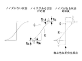
- TH R1 , TH R2 , TH B1 , and TH B2 for example, as shown in FIG. 12, for example, a difference between standard deviations indicating noise amounts of G and R or G and B at a pixel position to be processed is illustrated. be able to.
- the R, G, and B noise amounts in one direction D1 and the other direction D2 are expressed by the following formulas (156) to (159) as Nr D1 , Ng D1 , Nb D1 , Nr D2 , Ng D2 , and Nb D2 , respectively. be able to.
- TH R1 Nr D1 -Ng D1 (156)
- TH R2 Nr D2 -Ng D2
- TH B1 Nb D1 -Ng D1 (158)
- TH B2 Nb D2 -Ng D2 (159)
- the target pixel may be detected as a starting point of axial chromatic aberration.
- TH R and TH B are arbitrary constants.
- TH R and TH B As the constants TH R and TH B, as shown in FIG. 13, for example, a difference between G and R or G and B pixel values at a pixel position to be processed can be exemplified.
- the pixel values of R, G, and B of the pixel of interest are Pr (0, 0), Pg (0, 0), and Pb (0, 0)
- the following equations (164) and (165) are obtained.
- TH R Pg (0,0)-Pr (0,0) (164)
- TH B Pg (0,0)-Pb (0,0) (165)
- the target pixel may be detected as an origin of axial chromatic aberration.
- K R, K B is an arbitrary constant.
- K R and K B the ratio of G and R or G and B pixel values at the pixel position to be processed can be exemplified.
- the pixel values of R, G, and B of the pixel of interest are Pr (0, 0), Pg (0, 0), and Pb (0, 0)
- the following expressions (170) and (171) are obtained.
- K R Pg (0,0) / Pr (0,0) (170)
- K B Pg (0,0) / Pb (0,0) (171)
- This also has the advantage that it is possible to detect the origin of axial chromatic aberration that occurs on a colored subject, not an achromatic color.
- the total pixel value is calculated by the mathematical formulas shown in Equations 2 and 3.
- the total pixel value is calculated by the mathematical formulas shown in Equation 4 and Equation 5.
- the total pixel value is calculated by the mathematical formulas shown in Equation 6 and Equation 7.
- the total pixel value is calculated by the mathematical formulas shown in Formula 8 and Formula 9.
- the image processing apparatus 1 is used by being mounted on a product such as a stationary broadcast camera, an ENG camera, a consumer handy camera, or a digital camera. It can also be used in an image signal correction program (CG program), an image editing apparatus, etc. that handle moving images.
- CG program image signal correction program
- the image processing method according to the present embodiment can also be used as an image processing program that causes a computer (for example, a personal computer) to execute the image processing method.
Landscapes
- Engineering & Computer Science (AREA)
- Multimedia (AREA)
- Signal Processing (AREA)
- Physics & Mathematics (AREA)
- Spectroscopy & Molecular Physics (AREA)
- Image Processing (AREA)
- Color Television Image Signal Generators (AREA)
Abstract
一列に並ぶ画素のうち注目画素を中心として一方向及び他方向に並ぶ画素の画素値を夫々色毎に合計する合計画素値算出部(10)と、合計画素値算出部による算出結果又は注目画素の画素値の少なくとも一方に基づいて、注目画素が軸上色収差の発生起点であるかを判定し発生起点を検出する発生起点検出部(11)と、発生起点を中心とする所定の周辺領域を軸上色収差領域と判定する領域判定部(12)と、発生起点に対して合計画素値算出部の算出結果に基づいて、一方向及び他方向につき特定色空間上の色空間情報を夫々算出する色空間情報算出部(15)と、一方向の色空間情報と他方向の色空間情報との差分を算出する色空間差分算出部(16)と、差分に応じて軸上色収差補正の補正量を算出する補正量算出部(17)と、補正量を用いて軸上色収差領域について補正する補正部(4)とを備える画像処理装置である。
Description
本発明は、画像処理装置、画像処理方法及び画像処理プログラムに関するものである。
通常の光学系を通して撮影された画像には軸上色収差が発生することが知られている。ここで、軸上色収差とは、光学系、撮像系及び画像処理系に起因し、光軸上の焦点位置が波長によって異なるために生じる偽色、すなわち本来の被写体には生じない色付きをいう。そして、このような軸上色収差を画像処理で補正するための技術が提案されている(例えば、特許文献1参照。)。
特許文献1では、画像データ中の注目画素について、偽色可能性を示すパラメータとして、白とびへの近さ、彩度の大きさ及び特定色相への近さを評価し、これらの少なくともいずれかを適用して軸上色収差を補正している。
特許文献1では、画像データ中の注目画素について、偽色可能性を示すパラメータとして、白とびへの近さ、彩度の大きさ及び特定色相への近さを評価し、これらの少なくともいずれかを適用して軸上色収差を補正している。
しかしながら、軸上色収差を補正するに際し、特許文献1のように注目画素について評価し、これに基づいて補正を行うだけでは不十分である。すなわち、いくつかの注目画素が本来同一色であったとしても、当該注目画素に隣接する画素との関係によって、人間にはその視覚特性上それら注目画素が互いに異なる色であるように見える。このため、人間の視覚特性に鑑みると、注目画素のみを評価して軸上色収差を補正するだけでは不十分となる。
本発明は、上述した事情に鑑みてなされたものであって、人間の視覚特性に基づいて軸上色収差を精度よく補正することを目的としている。
上記目的を達成するため、本発明は以下の手段を提供する。
本発明の一態様は、入力画像中の注目画素を含み一列に配列する複数の画素について、該注目画素を挟んで一方向及び他方向に配列する画素の画素値を夫々色毎に合計する合計画素値算出部と、該合計画素値算出部による算出結果又は前記注目画素の画素値の少なくとも一方に基づいて、前記注目画素が軸上色収差の発生起点であるか否かを判定し、発生起点を検出する発生起点検出部と、前記発生起点として検出された注目画素を中心とする所定の周辺領域を軸上色収差領域と判定する領域判定部と、前記発生起点として検出された前記注目画素に対し、前記合計画素値算出部による算出結果に基づいて、前記一方向及び前記他方向について特定色空間上の色空間情報を夫々算出する色空間情報算出部と、該色空間情報算出部により算出された前記一方向の色空間情報と前記他方向の色空間情報との差分を算出する色空間差分算出部と、該色空間差分算出部により算出された差分に応じて軸上色収差補正の補正量を算出する補正量算出部と、前記軸上色収差領域について前記補正量を用いて補正する補正部と、を備える画像処理装置である。
本発明の一態様は、入力画像中の注目画素を含み一列に配列する複数の画素について、該注目画素を挟んで一方向及び他方向に配列する画素の画素値を夫々色毎に合計する合計画素値算出部と、該合計画素値算出部による算出結果又は前記注目画素の画素値の少なくとも一方に基づいて、前記注目画素が軸上色収差の発生起点であるか否かを判定し、発生起点を検出する発生起点検出部と、前記発生起点として検出された注目画素を中心とする所定の周辺領域を軸上色収差領域と判定する領域判定部と、前記発生起点として検出された前記注目画素に対し、前記合計画素値算出部による算出結果に基づいて、前記一方向及び前記他方向について特定色空間上の色空間情報を夫々算出する色空間情報算出部と、該色空間情報算出部により算出された前記一方向の色空間情報と前記他方向の色空間情報との差分を算出する色空間差分算出部と、該色空間差分算出部により算出された差分に応じて軸上色収差補正の補正量を算出する補正量算出部と、前記軸上色収差領域について前記補正量を用いて補正する補正部と、を備える画像処理装置である。
本態様によれば、注目画素を挟む両側に一直線上に配列されている画素の画素値の合計を合計画素値算出部により算出し、この算出結果又は注目画素の画素値に基づいて発生起点検出部により注目画素が軸上色収差の発生起点であるか判定し、発生起点を検出する。注目画素が軸上色収差の発生起点であるとして検出された場合、色空間情報算出部により、注目画素について、特定色空間上の色空間情報を一方向及び他方向について夫々算出し、色空間差分算出部によりこれらの差分を算出する。そして、この差分に基づいて算出された補正量を用いて、注目画素を中心とする周辺領域からなる軸上色収差領域について補正処理を行う。このように、注目画素だけでなく、注目画素を挟んで両側に一直線上に配列されている画素の画素値をも評価した補正量を算出することで、人間の視覚特性に基づいて軸上色収差補正を行うことができる。
上記態様においては、前記色空間情報算出部が、特定色空間上の色空間情報として、色の角度に関する情報、色の強度に関する情報、及び色の明るさに関する情報の少なくとも1つを算出し、前記色空間差分算出部が、前記色空間情報算出部による算出結果に基づいて、前記一方向の色空間情報と前記他方向の色空間情報との差分として、前記色の角度の差分、前記色の強度の差分、及び前記色の明るさの差分のうち少なくとも1つを算出し、前記補正量算出部が、前記色空間差分算出部による算出結果に基づいて軸上色収差補正の補正量を算出することとしてもよい。
このようにすることで、人間がその視覚特性上、軸上色収差を知覚しやすい隣接する領域の色の角度の差、色の強度の差、明るさの差に応じた最適な補正量を算出することができる。
このようにすることで、人間がその視覚特性上、軸上色収差を知覚しやすい隣接する領域の色の角度の差、色の強度の差、明るさの差に応じた最適な補正量を算出することができる。
また上記様態においては、前記補正量算出部が、前記色の角度の差分が180度に近いほど大きな補正量を算出し、180度から離れている程小さな補正量を算出することとしてもよい。
このようにすることで、色空間の角度を色相環のように0度から360度で表した場合に、2つの色が対極となる180度のように、人間の視覚的に色付きが検知されやすい場合に適切な補正量を算出することができる。
このようにすることで、色空間の角度を色相環のように0度から360度で表した場合に、2つの色が対極となる180度のように、人間の視覚的に色付きが検知されやすい場合に適切な補正量を算出することができる。
また上記様態においては、前記補正量算出部が、前記色の強度の差分の絶対値が大きいほど大きな補正量を算出し、絶対値が小さいほど小さな補正量を算出することとしてもよい。
このようにすることで、色の強度の差分が大きく、人間の視覚的に色付きが検知されやすい場合に適切な補正量を算出することができる。
このようにすることで、色の強度の差分が大きく、人間の視覚的に色付きが検知されやすい場合に適切な補正量を算出することができる。
また上記様態においては、前記補正量算出部が、前記色の明るさの差分の絶対値が大きいほど大きな補正量を算出し、絶対値が小さいほど小さな補正量を算出することとしてもよい。
このようにすることで、色の明るさの差分が大きく、人間の視覚的に色付きが検知されやすい場合にも適切な補正量を算出することができる。
このようにすることで、色の明るさの差分が大きく、人間の視覚的に色付きが検知されやすい場合にも適切な補正量を算出することができる。
また上記様態においては、前記補正量算出部が、前記色の角度が前記一方向と前記他方向で同方向となる補正量を算出することとしてもよい。
このようにすることで、補正後に色の角度の差分がなくなり、人間の視覚的に色付きに対する望ましい補正量を算出することができる。
このようにすることで、補正後に色の角度の差分がなくなり、人間の視覚的に色付きに対する望ましい補正量を算出することができる。
また上記様態においては、前記補正量算出部が、前記色の強度が前記一方向と前記他方向とで同一となる補正量を算出することとしてもよい。
このようにすることで、補正後に色の強度の差分がなくなり、人間の視覚的に色付きに対する望ましい補正量を算出することができる。
このようにすることで、補正後に色の強度の差分がなくなり、人間の視覚的に色付きに対する望ましい補正量を算出することができる。
また上記様態においては、前記補正量算出部が、前記色の明るさが前記一方向と前記他方向とで同一となる補正量を算出することとしてもよい。
このようにすることで、補正後に色の明るさの差分がなくなり、人間の視覚的に色付きに対する望ましい補正量を算出することができる。
このようにすることで、補正後に色の明るさの差分がなくなり、人間の視覚的に色付きに対する望ましい補正量を算出することができる。
また上記様態においては、前記特定色空間が、HSV空間であることとしてもよい。
このようにすることで、比較的に低い計算コストで色空間の算出を行うことができる。
このようにすることで、比較的に低い計算コストで色空間の算出を行うことができる。
また上記様態においては、前記特定色空間が、L*a*b*空間であることとしてもよい。
このようにすることで、人間の視覚的な感覚に近い色空間の算出を行うことができる。
このようにすることで、人間の視覚的な感覚に近い色空間の算出を行うことができる。
また、上記態様においては、前記発生起点検出部が、前記注目画素の画素値が所定の閾値よりも大きい場合、又は、前記合計画素値算出部により算出された前記一方向に配列している画素のGの画素値の合計とRの画素値の合計との大小関係が、前記他方向に配列している画素のGの画素値の合計とRの画素値の合計との大小関係と逆である場合、若しくは、前記一方向に配列している画素のGの画素値の合計とBの画素値の合計との大小関係が、前記他方向に配列している画素のGの画素値の合計とBの画素値の合計との大小関係と逆である場合に、前記注目画素を軸上色収差の発生起点として検出することとしてもよい。
このようにすることで、近飽和領域、近飽和以外の領域の少なくとも一方を軸上色収差の発生起点として検出することができる。
このようにすることで、近飽和領域、近飽和以外の領域の少なくとも一方を軸上色収差の発生起点として検出することができる。
また、上記態様においては、前記発生起点検出部が、以下の条件式を満足する場合に、前記注目画素を軸上色収差の発生起点であると判定してもよい。
PgD1>PrD1
PgD2<PrD2
ここで、PgD1は前記注目画素から前記一方向に配列している画素のGの画素値の合計、PgD2は前記注目画素から前記他方向に配列している画素のGの画素値の合計、PrD1は前記注目画素から前記一方向に配列している画素のRの画素値の合計、PrD2は前記注目画素から前記他方向に配列している画素のRの画素値の合計である。
このようにすることで、フォーカス位置近傍における軸上色収差の発生起点を検出することができる。
PgD1>PrD1
PgD2<PrD2
ここで、PgD1は前記注目画素から前記一方向に配列している画素のGの画素値の合計、PgD2は前記注目画素から前記他方向に配列している画素のGの画素値の合計、PrD1は前記注目画素から前記一方向に配列している画素のRの画素値の合計、PrD2は前記注目画素から前記他方向に配列している画素のRの画素値の合計である。
このようにすることで、フォーカス位置近傍における軸上色収差の発生起点を検出することができる。
また、上記態様においては、前記発生起点検出部が、以下の条件式を満足する場合に、前記注目画素を軸上色収差の発生起点であると判定してもよい。
PgD1>PbD1
PgD2<PbD2
ここで、PgD1は前記注目画素から前記一方向に配列している画素のGの画素値の合計、PgD2は前記注目画素から前記他方向に配列している画素のGの画素値の合計、PbD1は前記注目画素から前記一方向に配列している画素のBの画素値の合計、PbD2は前記注目画素から前記他方向に配列している画素のBの画素値の合計である。
このようにすることによっても、フォーカス位置近傍における軸上色収差の発生起点を検出することができる。
PgD1>PbD1
PgD2<PbD2
ここで、PgD1は前記注目画素から前記一方向に配列している画素のGの画素値の合計、PgD2は前記注目画素から前記他方向に配列している画素のGの画素値の合計、PbD1は前記注目画素から前記一方向に配列している画素のBの画素値の合計、PbD2は前記注目画素から前記他方向に配列している画素のBの画素値の合計である。
このようにすることによっても、フォーカス位置近傍における軸上色収差の発生起点を検出することができる。
また、上記態様においては、前記発生起点検出部が、以下の条件式を満足する場合に、前記注目画素を軸上色収差の発生起点であると判定してもよい。
PgD1>PrD1
PgD2<PrD2
PgD2<PbD2
ここで、PgD1は前記注目画素から前記一方向に配列している画素のGの画素値の合計、PgD2は前記注目画素から前記他方向に配列している画素のGの画素値の合計、PrD1は前記注目画素から前記一方向に配列している画素のRの画素値の合計、PrD2は前記注目画素から前記他方向に配列している画素のRの画素値の合計、PbD2は前記注目画素から前記他方向に配列している画素のBの画素値の合計である。
このようにすることで、他方向にパープルフリンジが発生し、一方向のRの画素値の合計が、Gの画素値の合計より小さく、色相環で反対色に近い色となってパープルフリンジが目立つ場所を軸上色収差の発生起点として検出することができる。
PgD1>PrD1
PgD2<PrD2
PgD2<PbD2
ここで、PgD1は前記注目画素から前記一方向に配列している画素のGの画素値の合計、PgD2は前記注目画素から前記他方向に配列している画素のGの画素値の合計、PrD1は前記注目画素から前記一方向に配列している画素のRの画素値の合計、PrD2は前記注目画素から前記他方向に配列している画素のRの画素値の合計、PbD2は前記注目画素から前記他方向に配列している画素のBの画素値の合計である。
このようにすることで、他方向にパープルフリンジが発生し、一方向のRの画素値の合計が、Gの画素値の合計より小さく、色相環で反対色に近い色となってパープルフリンジが目立つ場所を軸上色収差の発生起点として検出することができる。
また、上記態様においては、前記発生起点検出部が、以下の条件式を満足する場合に、前記注目画素を軸上色収差の発生起点であると判定してもよい。
PgD1>PbD1
PgD2<PrD2
PgD2<PbD2
ここで、PgD1は前記注目画素から前記一方向に配列している画素のGの画素値の合計、PgD2は前記注目画素から前記他方向に配列している画素のGの画素値の合計、PrD2は前記注目画素から前記他方向に配列している画素のRの画素値の合計、PbD1は前記注目画素から前記一方向に配列している画素のBの画素値の合計、PbD2は前記注目画素から前記他方向に配列している画素のBの画素値の合計である。
このようにすることによっても、他方向にパープルフリンジが発生し、一方向のBの画素値の合計が、Gの画素値の合計より小さく、色相環で反対色に近い色となってパープルフリンジが目立つ場所を軸上色収差の発生起点として検出することができる。
PgD1>PbD1
PgD2<PrD2
PgD2<PbD2
ここで、PgD1は前記注目画素から前記一方向に配列している画素のGの画素値の合計、PgD2は前記注目画素から前記他方向に配列している画素のGの画素値の合計、PrD2は前記注目画素から前記他方向に配列している画素のRの画素値の合計、PbD1は前記注目画素から前記一方向に配列している画素のBの画素値の合計、PbD2は前記注目画素から前記他方向に配列している画素のBの画素値の合計である。
このようにすることによっても、他方向にパープルフリンジが発生し、一方向のBの画素値の合計が、Gの画素値の合計より小さく、色相環で反対色に近い色となってパープルフリンジが目立つ場所を軸上色収差の発生起点として検出することができる。
また、上記態様においては、前記発生起点検出部が、以下の条件式を満足する場合に、前記注目画素を軸上色収差の発生起点であると判定してもよい。
PgD1>PrD1
PgD1>PbD1
PgD2<PrD2
ここで、PgD1は前記注目画素から前記一方向に配列している画素のGの画素値の合計、PgD2は前記注目画素から前記他方向に配列している画素のGの画素値の合計、PrD1は前記注目画素から前記一方向に配列している画素のRの画素値の合計、PrD2は前記注目画素から前記他方向に配列している画素のRの画素値の合計、PbD1は前記注目画素から前記一方向に配列している画素のBの画素値の合計である。
PgD1>PrD1
PgD1>PbD1
PgD2<PrD2
ここで、PgD1は前記注目画素から前記一方向に配列している画素のGの画素値の合計、PgD2は前記注目画素から前記他方向に配列している画素のGの画素値の合計、PrD1は前記注目画素から前記一方向に配列している画素のRの画素値の合計、PrD2は前記注目画素から前記他方向に配列している画素のRの画素値の合計、PbD1は前記注目画素から前記一方向に配列している画素のBの画素値の合計である。
このようにすることで、一方向にグリーンフリンジが発生し、他方向のRの画素値の合計がGの画素値の合計より大きく、色相環で反対色に近い色となってグリーンフリンジが目立つ場所を軸上色収差の発生起点として検出することができる。
また、上記態様においては、前記発生起点検出部が、以下の条件式を満足する場合に、前記注目画素を軸上色収差の発生起点であると判定してもよい。
PgD1>PrD1
PgD1>PbD1
PgD2<PbD2
ここで、PgD1は前記注目画素から前記一方向に配列している画素のGの画素値の合計、PgD2は前記注目画素から前記他方向に配列している画素のGの画素値の合計、PrD1は前記注目画素から前記一方向に配列している画素のRの画素値の合計、PbD1は前記注目画素から前記一方向に配列している画素のBの画素値の合計、PbD2は前記注目画素から前記他方向に配列している画素のBの画素値の合計である。
PgD1>PrD1
PgD1>PbD1
PgD2<PbD2
ここで、PgD1は前記注目画素から前記一方向に配列している画素のGの画素値の合計、PgD2は前記注目画素から前記他方向に配列している画素のGの画素値の合計、PrD1は前記注目画素から前記一方向に配列している画素のRの画素値の合計、PbD1は前記注目画素から前記一方向に配列している画素のBの画素値の合計、PbD2は前記注目画素から前記他方向に配列している画素のBの画素値の合計である。
このようにすることによっても、一方向にグリーンフリンジが発生し、他方向のBの画素値の合計がGの画素値の合計より大きく、色相環で反対色に近い色となってグリーンフリンジが目立つ場所を軸上色収差の発生起点として検出することができる。
また、上記態様においては、前記発生起点検出部が、以下の条件式を満足する場合に、前記注目画素を軸上色収差の発生起点であると判定してもよい。
PgD1+THR1>PrD1
PgD2-THR2<PrD2
PgD1+THB1>PbD1
PgD2-THB2<PbD2
ここで、PgD1は前記注目画素から前記一方向に配列している画素のGの画素値の合計、PgD2は前記注目画素から前記他方向に配列している画素のGの画素値の合計、PrD1は前記注目画素から前記一方向に配列している画素のRの画素値の合計、PrD2は前記注目画素から前記他方向に配列している画素のRの画素値の合計、PbD1は前記注目画素から前記一方向に配列している画素のBの画素値の合計、PbD2は前記注目画素から前記他方向に配列している画素のBの画素値の合計、THR1,THR2,THB1,THB2は任意の定数である。
このようにすることで、THR1,THR2,THB1,THB2を適当に選択することにより、ノイズの影響を低減し、軸上色収差の発生起点を安定して検出することができる。
PgD1+THR1>PrD1
PgD2-THR2<PrD2
PgD1+THB1>PbD1
PgD2-THB2<PbD2
ここで、PgD1は前記注目画素から前記一方向に配列している画素のGの画素値の合計、PgD2は前記注目画素から前記他方向に配列している画素のGの画素値の合計、PrD1は前記注目画素から前記一方向に配列している画素のRの画素値の合計、PrD2は前記注目画素から前記他方向に配列している画素のRの画素値の合計、PbD1は前記注目画素から前記一方向に配列している画素のBの画素値の合計、PbD2は前記注目画素から前記他方向に配列している画素のBの画素値の合計、THR1,THR2,THB1,THB2は任意の定数である。
このようにすることで、THR1,THR2,THB1,THB2を適当に選択することにより、ノイズの影響を低減し、軸上色収差の発生起点を安定して検出することができる。
また、上記態様においては、前記発生起点検出部が、以下の条件式を満足する場合に、前記注目画素を軸上色収差の発生起点であると判定してもよい。
PgD1+THR>PrD1
PgD2+THR<PrD2
PgD1+THB>PbD1
PgD2+THB<PbD2
ここで、PgD1は前記注目画素から前記一方向に配列している画素のGの画素値の合計、PgD2は前記注目画素から前記他方向に配列している画素のGの画素値の合計、PrD1は前記注目画素から前記一方向に配列している画素のRの画素値の合計、PrD2は前記注目画素から前記他方向に配列している画素のRの画素値の合計、PbD1は前記注目画素から前記一方向に配列している画素のBの画素値の合計、PbD2は前記注目画素から前記他方向に配列している画素のBの画素値の合計、THR,THBは任意の定数である。
このようにすることで、THR,THBを適当に選択することにより、無彩色ではなく、色付き被写体上に発生した軸上色収差の発生起点を検出することができる。
PgD1+THR>PrD1
PgD2+THR<PrD2
PgD1+THB>PbD1
PgD2+THB<PbD2
ここで、PgD1は前記注目画素から前記一方向に配列している画素のGの画素値の合計、PgD2は前記注目画素から前記他方向に配列している画素のGの画素値の合計、PrD1は前記注目画素から前記一方向に配列している画素のRの画素値の合計、PrD2は前記注目画素から前記他方向に配列している画素のRの画素値の合計、PbD1は前記注目画素から前記一方向に配列している画素のBの画素値の合計、PbD2は前記注目画素から前記他方向に配列している画素のBの画素値の合計、THR,THBは任意の定数である。
このようにすることで、THR,THBを適当に選択することにより、無彩色ではなく、色付き被写体上に発生した軸上色収差の発生起点を検出することができる。
また、上記態様においては、前記発生起点検出部が、以下の条件式を満足する場合に、前記注目画素を軸上色収差の発生起点であると判定してもよい。
PgD1>PrD1×KR
PgD2<PrD2×KR
PgD1>PbD1×KB
PgD2<PbD2×KB
ここで、PgD1は前記注目画素から前記一方向に配列している画素のGの画素値の合計、PgD2は前記注目画素から前記他方向に配列している画素のGの画素値の合計、PrD1は前記注目画素から前記一方向に配列している画素のRの画素値の合計、PrD2は前記注目画素から前記他方向に配列している画素のRの画素値の合計、PbD1は前記注目画素から前記一方向に配列している画素のBの画素値の合計、PbD2は前記注目画素から前記他方向に配列している画素のBの画素値の合計、KR,KBは任意の定数である。
このようにすることによっても、KR,KBを適当に選択することにより、無彩色ではなく、色付き被写体上に発生した軸上色収差の発生起点を検出することができる。
PgD1>PrD1×KR
PgD2<PrD2×KR
PgD1>PbD1×KB
PgD2<PbD2×KB
ここで、PgD1は前記注目画素から前記一方向に配列している画素のGの画素値の合計、PgD2は前記注目画素から前記他方向に配列している画素のGの画素値の合計、PrD1は前記注目画素から前記一方向に配列している画素のRの画素値の合計、PrD2は前記注目画素から前記他方向に配列している画素のRの画素値の合計、PbD1は前記注目画素から前記一方向に配列している画素のBの画素値の合計、PbD2は前記注目画素から前記他方向に配列している画素のBの画素値の合計、KR,KBは任意の定数である。
このようにすることによっても、KR,KBを適当に選択することにより、無彩色ではなく、色付き被写体上に発生した軸上色収差の発生起点を検出することができる。
また、上記態様においては、前記画像が、各画素にRGB全ての画素値を有していてもよい。
このようにすることで、各画素においてRGB全ての画素値を同時に取得する同時化された画像に対しても軸上色収差の発生起点を検出する処理を行うことができる。
このようにすることで、各画素においてRGB全ての画素値を同時に取得する同時化された画像に対しても軸上色収差の発生起点を検出する処理を行うことができる。
また、上記態様においては、前記画像が、各画素においてRGBの少なくとも1つの画素値が欠落した画素値を有していてもよい。
このようにすることで、各画素においてRGB全ての画素値が同時に取得されない、同時化されていない画像に対しても軸上色収差の発生起点を検出することができ、検出時に同時化のための補間エラーの影響をなくすことができる。
このようにすることで、各画素においてRGB全ての画素値が同時に取得されない、同時化されていない画像に対しても軸上色収差の発生起点を検出することができ、検出時に同時化のための補間エラーの影響をなくすことができる。
また、本発明の他の態様は、入力画像中の注目画素を含み一列に配列する複数の画素について、該注目画素を挟んで一方向及び他方向に配列する画素の画素値を夫々色毎に合計する合計画素値算出ステップと、該合計画素値算出ステップにおける算出結果又は前記注目画素の画素値の少なくとも一方に基づいて、前記注目画素を軸上色収差の発生起点として検出する発生起点検出ステップと、前記発生起点として検出された注目画素を中心とする所定の周辺領域を軸上色収差領域と判定する領域判定ステップと、前記発生起点として検出された前記注目画素に対し、前記合計画素値算出ステップにおける算出結果に基づいて、前記一方向及び前記他方向について特定色空間上の色空間情報を夫々算出する色空間情報算出ステップと、該色空間情報算出ステップにおいて算出された前記一方向の色空間情報と前記他方向の色空間情報との差分を算出する色空間差分算出ステップと、該色空間差分算出ステップにおいて算出された差分に応じて軸上色収差補正の補正量を算出する補正量算出ステップと、前記軸上色収差領域について前記補正量を用いて補正する補正ステップと、を備える画像処理方法である。
上記他の態様において、前記色空間情報算出ステップにおいて、特定色空間上の色空間情報として、色の角度に関する情報、色の強度に関する情報、及び色の明るさに関する情報の少なくとも1つを算出し、前記色空間差分算出ステップにおいて、前記色空間情報算出ステップによる算出結果に基づいて、前記一方向の色空間情報と前記他方向の色空間情報との差分として、前記色の角度の差分、前記色の強度の差分、及び前記色の明るさの差分のうち少なくとも1つを算出し、前記補正量算出ステップにおいて、前記色空間差分算出ステップによる算出結果に基づいて軸上色収差補正の補正量を算出することとしてもよい。
また、上記他の態様において、前記発生起点検出ステップにおいて、前記注目画素の画素値が所定の閾値よりも大きい場合、又は、前記合計画素値算出部により算出された前記一方向に配列している画素のGの画素値の合計とRの画素値の合計との大小関係が、前記他方向に配列している画素のGの画素値の合計とRの画素値の合計との大小関係と逆である場合、若しくは、前記一方向に配列している画素のGの画素値の合計とBの画素値の合計との大小関係が、前記他方向に配列している画素のGの画素値の合計とBの画素値の合計との大小関係と逆である場合に、前記注目画素を軸上色収差の発生起点として検出することとしてもよい。
また、本発明の他の態様は、入力画像中の注目画素を含み一列に配列する複数の画素について、該注目画素を挟んで一方向及び他方向に配列する画素の画素値を夫々色毎に合計する合計画素値算出ステップと、該合計画素値算出ステップにおける算出結果又は前記注目画素の画素値の少なくとも一方に基づいて、前記注目画素を軸上色収差の発生起点として検出する発生起点検出ステップと、前記発生起点として検出された注目画素を中心とする所定の周辺領域を軸上色収差領域と判定する領域判定ステップと、前記発生起点として検出された前記注目画素に対し、前記合計画素値算出ステップにおける算出結果に基づいて、前記一方向及び前記他方向について特定色空間上の色空間情報を夫々算出する色空間情報算出ステップと、該色空間情報算出ステップにおいて算出された前記一方向の色空間情報と前記他方向の色空間情報との差分を算出する色空間差分算出ステップと、該色空間差分算出ステップにおいて算出された差分に応じて軸上色収差補正の補正量を算出する補正量算出ステップと、前記軸上色収差領域について前記補正量を用いて補正する補正ステップと、をコンピュータに実行させる画像処理プログラムである。
上記他の態様において、前記コンピュータが、前記色空間情報算出ステップにおいて、特定色空間上の色空間情報として、色の角度に関する情報、色の強度に関する情報、及び色の明るさに関する情報の少なくとも1つを算出し、前記色空間差分算出ステップにおいて、前記色空間情報算出ステップによる算出結果に基づいて、前記一方向の色空間情報と前記他方向の色空間情報との差分として、前記色の角度の差分、前記色の強度の差分、及び前記色の明るさの差分のうち少なくとも1つを算出し、前記補正量算出ステップにおいて、前記色空間差分算出ステップによる算出結果に基づいて軸上色収差補正の補正量を算出することとしてもよい。
また、上記他の態様において、前記コンピュータが、前記発生起点検出ステップにおいて、前記注目画素の画素値が所定の閾値よりも大きい場合、又は、前記合計画素値算出部により算出された前記一方向に配列している画素のGの画素値の合計とRの画素値の合計との大小関係が、前記他方向に配列している画素のGの画素値の合計とRの画素値の合計との大小関係と逆である場合、若しくは、前記一方向に配列している画素のGの画素値の合計とBの画素値の合計との大小関係が、前記他方向に配列している画素のGの画素値の合計とBの画素値の合計との大小関係と逆である場合に、前記注目画素を軸上色収差の発生起点として検出することとしてもよい。
本発明によれば、近飽和領域もしくは近飽和領域以外の領域少なくとも一方においても軸上色収差を検出して人間の視覚特性に基づいて補正することができるという効果を奏する。
本発明の一実施形態に係る画像処理装置及び画像処理方法について、図面を参照して以下に説明する。
ここで、本実施形態に係る画像処理装置は、カメラにより取得された入力画像に対して後述する画像処理を施すものである。そして、画像処理装置1の処理対象である入力画像は、図示しない撮像光学系を通して入射された光線が固体撮像素子において電気信号に変換され、固定ノイズパターン除去及びアナログゲイン調整等が行われた後に、A/D変換器でディジタル信号に変換され、各種画像処理が施された画像信号である。この入力画像は、各画素においてRGB全ての信号値が得られるフルカラー画像であり、三板撮像素子により取得された三板カラー画像、もしくは、単板撮像素子により取得された単板カラー画像を各画素でRGB値が得られるように補間処理された画像である。
ここで、本実施形態に係る画像処理装置は、カメラにより取得された入力画像に対して後述する画像処理を施すものである。そして、画像処理装置1の処理対象である入力画像は、図示しない撮像光学系を通して入射された光線が固体撮像素子において電気信号に変換され、固定ノイズパターン除去及びアナログゲイン調整等が行われた後に、A/D変換器でディジタル信号に変換され、各種画像処理が施された画像信号である。この入力画像は、各画素においてRGB全ての信号値が得られるフルカラー画像であり、三板撮像素子により取得された三板カラー画像、もしくは、単板撮像素子により取得された単板カラー画像を各画素でRGB値が得られるように補間処理された画像である。
本実施形態に係る画像処理装置は、図1に示すように、入力画像において軸上色収差が発生している軸上色収差領域を抽出する領域抽出部2と、領域抽出部2により抽出された軸上色収差領域に対する補正量を算出する軸上色収差補正量算出部3と、軸上色収差領域の軸上色収差を補正した出力画像を出力する収差補正部4とを備えている。
領域抽出部2は、合計画素値算出部10、発生起点検出部11、及び領域判定部12を備えている。
合計画素値算出部10は、入力画像中の注目画素を設定し、設定された注目画素を含んで一列に配列している複数の画素について、注目画素を中心として一方向(D1)及び他方向(D2)に配列している画素の画素値を夫々色毎に合計する。
合計画素値算出部10は、入力画像中の注目画素を設定し、設定された注目画素を含んで一列に配列している複数の画素について、注目画素を中心として一方向(D1)及び他方向(D2)に配列している画素の画素値を夫々色毎に合計する。
発生起点検出部11は、注目画素の画素値、又は合計画素値算出部11により算出された注目画素を挟んで一方向に並ぶ画素の合計画素値若しくは他方向に並ぶ画素の合計画素値の少なくとも一方に基づいて、注目画素が軸上色収差の発生起点であるかを判定し、発生起点となる注目画素を検出する。
発生起点検出部5により検出する軸上色収差の発生起点とは、図2に示すように、例えば、注目画素のG画素値の大きさが飽和レベルになる注目画素、又は図3に示すように、注目画素を挟んで一直線に並ぶ一方向及び他方向の色が異なる場合の注目画素の少なくとも一方を意味している。
すなわち、図2及び図3に示すように、通常の光学系7では、波長の異なる光は光軸の奥行き方向に結像位置が異なることが知られている。一般にGに対して長波長のRは光軸方向の奥側に結像し、Gに対して短波長のBは光軸方向の手前側に結像する。このRGBの結像位置のずれが軸上色収差となって現れる。
すなわち、図2及び図3に示すように、通常の光学系7では、波長の異なる光は光軸の奥行き方向に結像位置が異なることが知られている。一般にGに対して長波長のRは光軸方向の奥側に結像し、Gに対して短波長のBは光軸方向の手前側に結像する。このRGBの結像位置のずれが軸上色収差となって現れる。
無彩色のステップエッジを撮影した場合、像面ではGがステップエッジの形状を有するが、R,Bは結像せずにステップエッジの形状が鈍っている。一方、像面奥では、Gは結像しないためステップエッジの形状が鈍っているが、Rが結像してステップエッジの形状を保持している。BはGよりさらに鈍った形状となる。
反対に、像面手前では、Gは結像しないためステップエッジの形状が鈍り、Bが結像してステップエッジの形状を保持している。RはGよりさらに鈍った形状となる。
反対に、像面手前では、Gは結像しないためステップエッジの形状が鈍り、Bが結像してステップエッジの形状を保持している。RはGよりさらに鈍った形状となる。
領域判定部12は、発生起点検出部5により検出された発生起点である注目画素の所定の周辺領域を軸上色収差領域として判定する。すなわち、注目画素が軸上色収差の発生起点として検出された場合には、軸上色収差の補正対象となるので、注目画素と注目画素を中心とする所定の周辺画素からなる領域を軸上色収差領域として判定する。軸上色収差領域としては、例えば、注目画素を中心とする5×5画素の領域や7×7画素の領域等、適宜設定することができる。
軸上色収差補正量算出部3は、色空間情報算出部15と、色空間差分算出部16と、補正量算出部17とを備えている。
色空間情報算出部15は、発生起点検出部5により発生起点であると検出された注目画素について、特定色空間上の色空間情報を、注目画素に対する一方向及び他方向の夫々について算出する。特定色空間としては、例えば、HSV空間やl*a*b空間などを適用することができる。そして、色空間情報は、合計画素値算出部10により算出された、注目画素を中心として一方向(D1)及び他方向(D2)に配列している画素についての色毎の画素値の合計に基づいて算出する。
色空間情報算出部15は、発生起点検出部5により発生起点であると検出された注目画素について、特定色空間上の色空間情報を、注目画素に対する一方向及び他方向の夫々について算出する。特定色空間としては、例えば、HSV空間やl*a*b空間などを適用することができる。そして、色空間情報は、合計画素値算出部10により算出された、注目画素を中心として一方向(D1)及び他方向(D2)に配列している画素についての色毎の画素値の合計に基づいて算出する。
色空間差分算出部16は、色空間情報算出部15により算出された一方向の色空間情報と他方向の色空間情報との差分を算出する。
補正量算出部17は、色空間差分算出部16により算出された差分に応じて軸上色収差領域に対する補正量を算出する。
収差補正部4は、補正量算出部17により算出された補正量を用いて軸上色収差領域を補正する。
補正量算出部17は、色空間差分算出部16により算出された差分に応じて軸上色収差領域に対する補正量を算出する。
収差補正部4は、補正量算出部17により算出された補正量を用いて軸上色収差領域を補正する。
以下に、このように構成された本実施形態に係る画像処理装置の作用としての画像処理方法について、図4のフローチャートを参照して説明する。
ステップS1において、合計画素値算出部10は、図5に示すように、入力画像中に注目画素(0,0)を設定し、次のステップS2(合計画素値算出ステップ)において、この注目画素を中心として、図5中の縦方向、横方向、右斜め方向及び左斜め方向の4方向について、注目画素を挟んで両側に並ぶ複数画素の画素値の合計を夫々算出する(ステップS2)。
具体的には、数1に示す式に従って、各方向の色毎の画素値の合計を算出する。
ステップS1において、合計画素値算出部10は、図5に示すように、入力画像中に注目画素(0,0)を設定し、次のステップS2(合計画素値算出ステップ)において、この注目画素を中心として、図5中の縦方向、横方向、右斜め方向及び左斜め方向の4方向について、注目画素を挟んで両側に並ぶ複数画素の画素値の合計を夫々算出する(ステップS2)。
具体的には、数1に示す式に従って、各方向の色毎の画素値の合計を算出する。
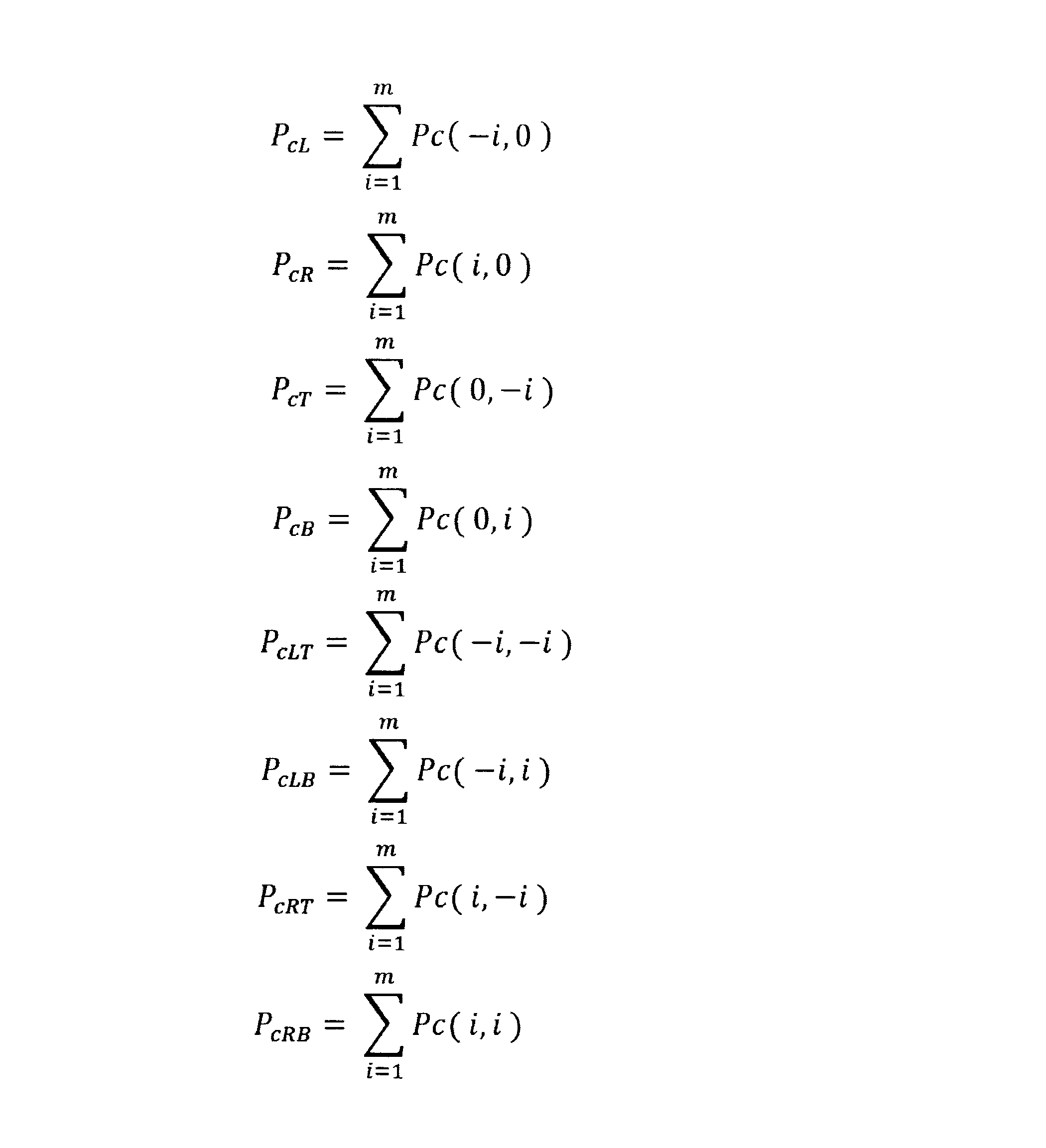
ここで、Pc(x,y)は、座標(x,y)に位置する画素の画素値、PcLは注目画素の左側の画素列の画素値の合計、PcRは注目画素の右側の画素列の画素値の合計、PcTは注目画素の上側の画素列の画素値の合計、PcBは注目画素の下側の画素列の画素値の合計、PcLTは注目画素の左上側の画素列の画素値の合計、PcLBは注目画素の左下側の画素列の画素値の合計、PcRTは注目画素の右上側の画素列の画素値の合計、PcRBは注目画素の右下側の画素列の画素値の合計である。また、添字cはカラーを意味し、r、g、bに置き換えることができ、置き換えることにより色毎の画素値の合計を算出する。また、i,mは正の整数である。
ステップS3(発生起点検出ステップ)において、発生起点検出部11は、以下の条件式(1)又は、合計画素値算出部10により算出された画素値の合計が、条件式(2)~(5)の全てを満たす場合に、注目画素を軸上色収差の発生起点として検出する。
条件式(1)は、注目画素のG画素値の大きさが任意の飽和レベル閾値THsatより大きい場合に、注目画素を軸上色収差の発生起点として検出することを示す。
条件式(1)は、注目画素のG画素値の大きさが任意の飽和レベル閾値THsatより大きい場合に、注目画素を軸上色収差の発生起点として検出することを示す。
Pg(0,0)>THsat …(1)
PgD1>PrD1 …(2)
PgD2<PrD2 …(3)
PgD1>PbD1 …(4)
PgD2<PbD2 …(5)
PgD1>PrD1 …(2)
PgD2<PrD2 …(3)
PgD1>PbD1 …(4)
PgD2<PbD2 …(5)
ここで、PgD1は注目画素から一方向D1に配列している画素のGの画素値の合計、PgD2は注目画素から他方向D2に配列している画素のGの画素値の合計、PrD1は注目画素から一方向D1に配列している画素のRの画素値の合計、PrD2は注目画素から他方向D2に配列している画素のRの画素値の合計、PbD1は注目画素から一方向D1に配列している画素のBの画素値の合計、PbD2は注目画素から他方向D2に配列している画素のBの画素値の合計である。
添字のD1は注目画素からの一方向であることを示し、例えば、数1におけるL、T、LT、LBが該当する。また、添字のD2は注目画素からの他方向であることを示し、例えば、R、B、RT、RBが該当する。方向の定義は任意であるが、D1としてL、T、LT、LBを選択した場合にはD2はR、B、RT、RBとなる。
なお、条件式(1)において、注目画素と任意の飽和レベル閾値THsatとを比較する際に、注目画素のG画素のみを用いることとしたが、必ずしもこれに限られない。例えば、飽和レベル閾値と輝度値とを比較することもできる他、その他公知の方法を用いることもできる。また、近飽和以外の領域の軸上色収差の発生起点を算出する方法についても上記した例に限られず、公知の方法を用いることができる。
ステップS4(検出情報生成ステップ)において、発生起点検出部11は、軸上色収差の発生起点であると検出された注目画素について「0」、発生起点ではないと検出された画素について「1」とする検出情報を生成する。発生起点検出部11は、注目画素が、軸上色収差の発生起点であると検出された場合、その画素位置に対応してPrD1,PrD2,PgD1,PgD2,PbD1,PbD2を保持する。
また、注目画素が、軸上色収差の発生起点であると検出された場合には、その画素位置と対応させて、図5中の縦方向、横方向、右斜め方向及び左斜め方向の4方向の何れの方向が上記条件式(2)~(5)を満たしたのかを保持し、その方向についての一方向D1及び他方向D2を保持する。
つまり、発生起点検出部11は、検出情報に関連する情報として、D1が、L、T、LT、LBの何れであるのか、及びD2がR、B、RT、RBの何れであるのかを保持しておく。
つまり、発生起点検出部11は、検出情報に関連する情報として、D1が、L、T、LT、LBの何れであるのか、及びD2がR、B、RT、RBの何れであるのかを保持しておく。
ステップS5(領域判定ステップ)において、領域判定部12は、注目画素が軸上色収差の発生起点であると検出された場合、すなわち、注目画素について発生起点検出部11により生成された検出情報が「0」であった場合、当該注目画素とその所定の周辺画素を含む領域を軸上色収差領域と判定する。軸上色収差領域として、例えば、検出情報が「0」である画素を中心とした7×7画素を含む領域の等、適宜設定することができる。
ステップS6(色空間情報算出ステップ)において、色空間情報算出部15は、検出情報が「0」であった画素位置に対応するPrD1,PgD1,PbD1及びPrD2,PgD2,PbD2から特定色空間の色空間情報を算出する。
例えば、特定色空間をHSV空間とすると、PrD1,PgD1,PbD1からPhD1,PsD1,PvD1の少なくとも1つを、PrD2,PgD2,PbD2からPhD2,PsD2,PvD2の内D1方向と同じ色空間情報を算出する。
例えば、特定色空間をHSV空間とすると、PrD1,PgD1,PbD1からPhD1,PsD1,PvD1の少なくとも1つを、PrD2,PgD2,PbD2からPhD2,PsD2,PvD2の内D1方向と同じ色空間情報を算出する。
なお、PhD1,PhD2は、発生起点であると検出された注目画素におけるD1方向、D2方向についての角度(色相)に関する色空間情報を示し、PsD1,PsD2は、発生起点であると検出された注目画素におけるD1方向、D2方向についての強度(彩度)に関する色空間情報を示し、PvD1,PvD2は、発生起点であると検出された注目画素におけるD1方向、D2方向についての明るさ(明度)に関する色空間情報を示す。
また、特定色空間をL*a*b*空間とすると、PrD1,PgD1,PbD1からPl*D1,Pa*D1,Pb*D1の少なくとも1つを、PrD2,PgD2,PbD2からPl*D2,Pa*D2,Pb*D2の内D1方向と同じ色空間情報を算出する。なお、Pl*D1,Pl*D2は、発生起点であると検出された注目画素におけるD1方向、D2方向についての明るさ(明度)に関する色空間情報を示し、Pa*D1,Pb*D1,Pa*D2,Pb*D2は、補色に関する情報であって、角度及び強度に関する色空間情報として利用することができる。
ステップS7(色空間差分算出ステップ)において、色空間差分算出部16により、2つの方向の色空間情報から色空間の差分を算出する。色区間情報算出部16は、差分として、色の角度の差分、色の強度の差分、明るさの差分の少なくとも1つを算出する。
ステップS8(補正量算出ステップ)では、色空間差分算出部16により算出された差分に基づいて、補正量を算出し、次のステップS9において、全ての画素について処理が行われたか判定し、全ての画素についての処理が完了していない場合には、ステップS1に戻り、処理が未だ行われていない画素を注目画素としてステップS2~S7の工程が繰り返される。
全ての画素について処理が行われた場合には、ステップS10(収差補正ステップ)において、領域判定部12により設定された軸上色収差領域について、補正量算出部17により算出された補正量を用いて収差補正部4により補正処理を実施し、処理を終了する。
上述したように、色空間情報として、色についての、角度、強度及び明るさの少なくとも一つを算出し、これらの色空間情報から角度の差分、強度の差分、明るさの差分の少なくとも一つを算出し、これら差分のうち何れか一又は複数を組み合わせた情報に基づいて補正量を算出し、軸上色収差領域の補正を行うことができる。
以下、角度の差分、強度の差分及び明るさの差分のうち、何れか1つまたは複数を組み合わせて補正量を算出する場合の具体例について説明する。
以下、角度の差分、強度の差分及び明るさの差分のうち、何れか1つまたは複数を組み合わせて補正量を算出する場合の具体例について説明する。
(角度に関する色空間情報に基づいて補正を行う場合)
色空間角度情報算出部15は、発生起点検出部11が検出情報に関連する情報として保持している2つの方向(D1,D2)について、角度に関する色空間情報を夫々算出する(ステップS6)。
色空間角度差分算出部16は、算出した角度に関する色空間情報からその差分を算出する(ステップS7)。
色空間角度情報算出部15は、発生起点検出部11が検出情報に関連する情報として保持している2つの方向(D1,D2)について、角度に関する色空間情報を夫々算出する(ステップS6)。
色空間角度差分算出部16は、算出した角度に関する色空間情報からその差分を算出する(ステップS7)。
具体的には、特定色空間がHSV空間である場合、角度に関する色空間情報として、PhD1,PhD2を算出し、これらの差分の絶対値Pangleを以下の式(6)に従って算出する。
Pangle=|PhD1-PhD2| …(6)
Pangle=|PhD1-PhD2| …(6)
また、特定色空間がL*a*b*空間である場合、角度に関する色空間情報として、Pa*D1,Pb*D1,Pa*D2,Pb*D2を算出し、これらの差分の絶対値Pangleを以下の式(7)に従って算出する。
Pangle=|tan-1(Pb*D1/Pa*D1)-
tan-1(Pb*D2/Pa*D2)| …(7)
Pangle=|tan-1(Pb*D1/Pa*D1)-
tan-1(Pb*D2/Pa*D2)| …(7)
ここで、発生起点検出部11において、条件式(1)を満たすことにより注目画素のG画素値の大きさが任意の飽和レベル閾値THsatより大きいとして、当該注目画素が発生起点と判定された場合は、特定方向のD1,D2が定まっていない。この場合には、例えば、上述した縦、横、斜めの計4つの全ての方向のD1,D2についてPangleを算出し、Pangleが最も大きい値を採用することができる。また、全ての方向のD1,D2についてPangleを算出し、これらの平均値を採用することもできる。
補正量算出部17は、Pangleから補正量Caを算出する。補正量Caは、例えば、Pangleが0から360度の値の場合、Pangleが180度に近い程補正量を大きくし、Pangleが180度から離れている程補正量を小さくする。色空間の角度を色相環のように0度から360度で表した場合に、2つの色が対極となる180度のように、人間の視覚的に色付きが検知されやすい場合に適切な補正量を算出することができる。色の角度が一方向と他方向で同方向となるような補正量を算出することで、補正後に色の角度の差分がなくなり、人間の視覚的に色付きに対する望ましい補正量を算出することができる。
そして、全ての画素について補正量が算出されると、角度に関する色空間情報から算出された補正量に基づく収差補正部の補正処理は、例えば、図6に示すように補正前の画素値をPr,Pg,Pb、図7に示すように補正後の画素値をPr’,Pg’,Pb’として以下の式(8)~(10)に従って行われる。
Pr’=Pr-Ca …(8)
Pg’=Pg …(9)
Pb’=Pb-Ca …(10)
Pg’=Pg …(9)
Pb’=Pb-Ca …(10)
また、補正前の画素値の角度をPa、補正後の画素値の角度をPa’として、以下の式(11)に従って補正を行うこともできる。
Pa’=Pa-Ca …(11)
Pa’=Pa-Ca …(11)
以下、角度に関する色空間情報に基づいて補正を行う場合の他の例について説明する。
色空間情報算出部15は、例えば、特定色空間がHSV空間である場合には、角度に関する色空間情報としてのPangle1,Pangle2を以下の式(12)及び式(13)に従って算出する。
Pangle1=PhD1 …(12)
Pangle2=PhD2 …(13)
色空間情報算出部15は、例えば、特定色空間がHSV空間である場合には、角度に関する色空間情報としてのPangle1,Pangle2を以下の式(12)及び式(13)に従って算出する。
Pangle1=PhD1 …(12)
Pangle2=PhD2 …(13)
また、特定色空間がL*a*b*空間である場合、角度に関する色空間情報としてPangle1,Pangle2を以下の式(14)及び式(15)に従って算出する。
Pangle1=tan-1(Pb*D1/Pa*D1) …(14)
Pangle2=tan-1(Pb*D2/Pa*D2) …(15)
Pangle1=tan-1(Pb*D1/Pa*D1) …(14)
Pangle2=tan-1(Pb*D2/Pa*D2) …(15)
ここで、発生起点検出部11において、条件式(1)を満たすことにより注目画素が発生起点と判定された場合には、特定方向のD1,D2が定まっていない。この場合には、色空間情報算出部15は、例えば、上述した縦、横、斜めの計4つの全ての方向のD1,D2でPangle1,Pangle2を算出し、色空間差分算出部16は、Pangle1とPangle2の差の絶対値の最大値を、角度に関する色空間情報の差分として採用し、最大の絶対値を示すD1,D2を特定方向とすることができる。
例えば、角度に関する色空間情報の差分の絶対値Pangleは式(16)により算出する。
Pangle=|Pangle1-Pangle2| …(16)
例えば、角度に関する色空間情報の差分の絶対値Pangleは式(16)により算出する。
Pangle=|Pangle1-Pangle2| …(16)
補正量算出部17はPangle,Pangle1,Pangle2から補正量Ca1,Ca2を、例えば、以下の式(17)~(20)に従って算出する。
Pangle1がPangle2より大きい場合
Ca1=Pangle …(17)
Ca2=0 …(18)
Pangle2がPangle1より大きい場合
Ca1=0 …(19)
Ca2=Pangle …(20)
Pangle1がPangle2より大きい場合
Ca1=Pangle …(17)
Ca2=0 …(18)
Pangle2がPangle1より大きい場合
Ca1=0 …(19)
Ca2=Pangle …(20)
入力画像中の全ての画素について処理が完了したら、軸上色収差領域について、補正量算出部17により算出された角度に基づく補正量を用いて収差補正部4により補正処理を実施する。
収差補正部4による角度に基づく補正処理は、例えば、図8に示すように補正対象の画素位置がD1方向の場合、補正前の画素値をPr1,Pg1,Pb1(図8)、補正後の画素値をPr1’,Pg1’,Pb1’(図9)として、以下の式(21)~(23)で表すことができる。
Pr1’=Pr-Ca1 …(21)
Pg1’=Pg …(22)
Pb1’=Pb-Ca1 …(23)
収差補正部4による角度に基づく補正処理は、例えば、図8に示すように補正対象の画素位置がD1方向の場合、補正前の画素値をPr1,Pg1,Pb1(図8)、補正後の画素値をPr1’,Pg1’,Pb1’(図9)として、以下の式(21)~(23)で表すことができる。
Pr1’=Pr-Ca1 …(21)
Pg1’=Pg …(22)
Pb1’=Pb-Ca1 …(23)
なお、補正前の画素値の角度をPangle1、補正後の画素値の角度をPangle1’とし、次の式(24)に従って補正処理を行うこともできる。。
Pangle1’=Pangle1-Ca1 …(24)
同様に、補正対象の画素位置がD2方向の場合、補正前の画素値をPr2,Pg2,Pb2、補正後の画素値をPr2’,Pg2’,Pb2’とし、次の式(25)~(27)に従って補正処理を行うことができる。
Pr2’=Pr-Ca2 …(25)
Pg2’=Pg …(26)
Pb2’=Pb-Ca2 …(27)
Pangle1’=Pangle1-Ca1 …(24)
同様に、補正対象の画素位置がD2方向の場合、補正前の画素値をPr2,Pg2,Pb2、補正後の画素値をPr2’,Pg2’,Pb2’とし、次の式(25)~(27)に従って補正処理を行うことができる。
Pr2’=Pr-Ca2 …(25)
Pg2’=Pg …(26)
Pb2’=Pb-Ca2 …(27)
また、補正前の画素値の角度をPangle2、補正後の画素値の角度をPaangle2’として、次の式(28)で補正処理を行うこともできる。
Pangle2’=Pangle2-Ca2 …(28)
Pangle2’=Pangle2-Ca2 …(28)
角度に基づく色空間情報に従って軸上色収差を補正する場合、画像処理等により色空間上で特定の色について角度の差が広がるような処理が行われる場合に特に有効である。
(強度に関する色空間情報に基づいて補正を行う場合)
色空間角度情報算出部15は、発生起点検出部11が検出情報に関連する情報として保持している2つの方向(D1,D2)について、強度に関する色空間情報を夫々算出する(ステップS6)。
色空間角度差分算出部16は、算出した強度に関する色空間情報からその差分を算出する(ステップS7)。
具体的には、特定色空間がHSV空間である場合、強度に関する色空間情報として、PsD1,PsD2を算出し、これらの差分の絶対値Pstrengthを以下の式(29)に従って算出する。
Pstrength=|PsD1-PsD2| …(29)
また、特定色空間がL*a*b*空間である場合、強度に関する色空間情報として、Pa*D1,Pb*D1,Pa*D2,Pb*D2を算出し、これらの差分の絶対値Pstrengthを以下の式(30)に従って算出する。
Pstrength=|√(Pa*D1^2+Pb*D1^2)-√(Pa*D2^2+Pb*D2^2)|…(30)
色空間角度情報算出部15は、発生起点検出部11が検出情報に関連する情報として保持している2つの方向(D1,D2)について、強度に関する色空間情報を夫々算出する(ステップS6)。
色空間角度差分算出部16は、算出した強度に関する色空間情報からその差分を算出する(ステップS7)。
具体的には、特定色空間がHSV空間である場合、強度に関する色空間情報として、PsD1,PsD2を算出し、これらの差分の絶対値Pstrengthを以下の式(29)に従って算出する。
Pstrength=|PsD1-PsD2| …(29)
また、特定色空間がL*a*b*空間である場合、強度に関する色空間情報として、Pa*D1,Pb*D1,Pa*D2,Pb*D2を算出し、これらの差分の絶対値Pstrengthを以下の式(30)に従って算出する。
Pstrength=|√(Pa*D1^2+Pb*D1^2)-√(Pa*D2^2+Pb*D2^2)|…(30)
発生起点検出部11において、条件式(1)を満たすことにより注目画素が発生起点と判定され、特定方向のD1,D2が定まっていない場合には、例えば、上述した縦、横、斜めの計4つの全ての方向のD1,D2でPstrengthを算出し、Pstrengthの最大値を採用し、その最大値を示すD1,D2を特定方向とすることができる。
補正量算出部17は、Pstrengthから以下の式(31)に従って、補正量Cbを算出する。Kは任意の定数とする。
Cb=K*Pstrength …(31)
補正量算出部17は、Pstrengthから以下の式(31)に従って、補正量Cbを算出する。Kは任意の定数とする。
Cb=K*Pstrength …(31)
入力画像中の全ての画素について処理が完了したら、軸上色収差領域について、補正量算出部により算出された強度に基づく補正量を用いて収差補正部4により補正処理を実施する。収差補正部4の強度に基づく補正処理は、例えば、図6に示すように補正前の画素値をPr,Pg,Pb、図7に示すように補正後の画素値をPr’,Pg’,Pb’とし、以下の式(32)~(34)で表すことができる。
Pr’=Pr-Cb …(32)
Pg’=Pg …(33)
Pb’=Pb-Cb …(34)
Pr’=Pr-Cb …(32)
Pg’=Pg …(33)
Pb’=Pb-Cb …(34)
また、補正前の画素値の強度をPs、補正後の画素値の強度をPs’とし、次の式(35)に従って補正処理を行うこともできる。
Ps’=Ps-Cb …(35)
Ps’=Ps-Cb …(35)
色の強度の差分の絶対値が大きいほど大きな補正量を算出し、絶対値が小さいほど小さな補正量を算出することで、色の強度の差分が大きく、人間の視覚的に色付きが検知されやすい場合に適切な補正量を算出することができる。
また、色の強度が一方向と他方向とで同一となる補正量を算出することで、補正後に色の強度の差分がなくなり、人間の視覚的に色付きに対する望ましい補正量を算出することができる。
また、色の強度が一方向と他方向とで同一となる補正量を算出することで、補正後に色の強度の差分がなくなり、人間の視覚的に色付きに対する望ましい補正量を算出することができる。
続いて、強度に関する色空間情報に基づいて補正を行う場合の他の例について説明する。色空間情報算出部15は、例えば、特定色空間がHSV空間である場合には、強度に関する色空間情報としてのPstrength1,Pstrength2を以下の式(36)及び式(37)に従って算出する
Pstrength1=PsD1 …(36)
Pstrength2=PsD2 …(37)
また、特定色空間がL*a*b*空間である場合、強度に関する色空間情報としてPstrength1,Pstrength2を以下の式(38)及び式(39)に従って算出する。
Pstrength1=√(Pa*D1^2+Pb*D1^2) …(38)
Pstrength2=√(Pa*D2^2+Pb*D2^2) …(39)
Pstrength1=PsD1 …(36)
Pstrength2=PsD2 …(37)
また、特定色空間がL*a*b*空間である場合、強度に関する色空間情報としてPstrength1,Pstrength2を以下の式(38)及び式(39)に従って算出する。
Pstrength1=√(Pa*D1^2+Pb*D1^2) …(38)
Pstrength2=√(Pa*D2^2+Pb*D2^2) …(39)
ここで、発生起点検出部11において、条件式(1)を満たすことにより注目画素が発生起点と判定され、特定方向のD1,D2が定まっていない場合、例えば、色空間情報算出部15が上述した縦、横、斜めの計4つの全ての方向のD1,D2でPstrength1,Pstrength2を算出し、色空間差分算出部16がPstrength1とPstrength2の差の絶対値の最大値を強度に関する色空間情報の差分として採用し、最大の絶対値を示すD1,D2を特定方向とすることができる。
例えば、強度に関する色空間情報の差分の絶対値Pstrengthは次の式(40)により算出する。
Pstrength=|Pstrength1-Pstrength2| …(40)
例えば、強度に関する色空間情報の差分の絶対値Pstrengthは次の式(40)により算出する。
Pstrength=|Pstrength1-Pstrength2| …(40)
補正量算出部17はPstrength,Pstrength1,Pstrength2から補正量Cb1,Cb2を、例えば、以下の式(41)~(44)に従って算出する。
Pstrength1がPstrength2より大きい場合
Cb1=Pstrength …(41)
Cb2=0 …(42)
Pstrength2がPstrength1より大きい場合
Cb1=0 …(43)
Cb2=Pstrength …(44)
Pstrength1がPstrength2より大きい場合
Cb1=Pstrength …(41)
Cb2=0 …(42)
Pstrength2がPstrength1より大きい場合
Cb1=0 …(43)
Cb2=Pstrength …(44)
入力画像中の全ての画素について処理が完了したら、軸上色収差領域について、補正量算出部17により算出された強度に基づく補正量を用いて収差補正部4により補正処理を実施する。
収差補正部17による強度に基づく補正処理は、例えば、図8に示すように補正対象の画素位置がD1方向の場合、補正前の画素値をPr1,Pg1,Pb1(図8)、補正後の画素値をPr1’,Pg1’,Pb1’(図9)として、以下の式次の式(45)~(47)で表すことができる。
Pr1’=Pr-Cb1 …(45)
Pg1’=Pg …(46)
Pb1’=Pb-Cb1 …(47)
Pr1’=Pr-Cb1 …(45)
Pg1’=Pg …(46)
Pb1’=Pb-Cb1 …(47)
なお、補正前の画素値の強度をPstrength1、補正後の画素値の強度をPstrength1’とし、次の式(48)に従って補正処理を行うこともできる。
Pstrength1’=Pstrength1-Cb1 …(48)
Pstrength1’=Pstrength1-Cb1 …(48)
同様に、補正対象の画素位置がD2方向の場合、補正前の画素値をPr2,Pg2,Pb2、補正後の画素値をPr2’,Pg2’,Pb2’とし、次の式(49)~(51)に従って補正処理を行うことができる。
Pr2’=Pr-Cb2 …(49)
Pg2’=Pg …(50)
Pb2’=Pb-Cb2 …(51)
Pr2’=Pr-Cb2 …(49)
Pg2’=Pg …(50)
Pb2’=Pb-Cb2 …(51)
また、補正前の画素値の強度をPstrength2、補正後の画素値の強度をPstrength2’として、次の式(52)で補正処理を行うこともできる。
Pstrength2’=Pstrength2-Cb2 …(52)
Pstrength2’=Pstrength2-Cb2 …(52)
強度に基づく色空間情報に従って軸上色収差を補正する場合、画像処理等により色空間上で特定の色の強度の差が広がるような処理が行われる場合に特に有効である。
(明度に関する色空間情報に基づいて補正を行う場合)
色空間角度情報算出部15は、発生起点検出部11が検出情報に関連する情報として保持している2つの方向(D1,D2)について、明るさに関する色空間情報を夫々算出する(ステップS6)。
色空間角度差分算出部16は、算出した明るさに関する色空間情報からその差分を算出する(ステップS7)。
色空間角度情報算出部15は、発生起点検出部11が検出情報に関連する情報として保持している2つの方向(D1,D2)について、明るさに関する色空間情報を夫々算出する(ステップS6)。
色空間角度差分算出部16は、算出した明るさに関する色空間情報からその差分を算出する(ステップS7)。
具体的には、特定色空間がHSV空間である場合、明るさに関する色空間情報として、PvD1,PvD2を算出し、これらの差分の絶対値Plightnessを以下の式(53)に従って算出する。
色空間の2つの明るさの差の絶対値Plightnessは次式で表される。
Plightness=|PvD1-PvD2| …(53)
色空間の2つの明るさの差の絶対値Plightnessは次式で表される。
Plightness=|PvD1-PvD2| …(53)
また、特定色空間がL*a*b*空間である場合、強度に関する色空間情報として、Pl*D1,Pl*D2を算出し、これらの差分の絶対値Plightnessを次の式(54)に従って算出する。
Plightness=|Pl*D1-Pl*D2| …(54)
Plightness=|Pl*D1-Pl*D2| …(54)
発生起点検出部11において、条件式(1)を満たすことにより注目画素が発生起点と判定され、特定方向のD1,D2が定まっていない場合には、例えば、上述した縦、横、斜めの計4つの全ての方向のD1,D2でPlightnessを算出し、Plightnessの最大値を採用し、その最大値を示すD1,D2を特定方向とすることができる。
補正量算出部17は、Plightnessから以下の式に従って、補正量Ccを算出する。Kは任意の定数とする。
Cc=K*Plightness …(55)
Cc=K*Plightness …(55)
入力画像中の全ての画素について処理が完了したら、軸上色収差領域について、補正量算出部により算出された明るさに基づく補正量を用いて収差補正部4により補正処理を実施する。
収差補正部の補正処理は、図7に示すように補正後の画素値をPr’,Pg’,Pb’とし、以下の式(56)~(58)で表すことができる。
Pr’=Pr-Cc …(56)
Pg’=Pg …(57)
Pb’=Pb-Cc …(58)
収差補正部の補正処理は、図7に示すように補正後の画素値をPr’,Pg’,Pb’とし、以下の式(56)~(58)で表すことができる。
Pr’=Pr-Cc …(56)
Pg’=Pg …(57)
Pb’=Pb-Cc …(58)
また、補正前の画素値の明度をPl、補正後の画素値の強度をPl’とし、次の式(59)に従って補正処理を行うこともできる。
Pl’=Pl-Cc …(59)
Pl’=Pl-Cc …(59)
色の明るさの差分の絶対値が大きいほど大きな補正量を算出し、絶対値が小さいほど小さな補正量を算出することで、色の明るさの差分が大きく、人間の視覚的に色付きが検知されやすい場合にも適切な補正量を算出することができる。
また、色の明るさが一方向と他方向とで同一となるような補正量を算出することで、補正後に色の明るさの差分がなくなり、人間の視覚的に色付きに対する望ましい補正量を算出することができる。
また、色の明るさが一方向と他方向とで同一となるような補正量を算出することで、補正後に色の明るさの差分がなくなり、人間の視覚的に色付きに対する望ましい補正量を算出することができる。
続いて、明るさに関する色空間情報に基づいて補正を行う場合の他の例について説明する。色空間情報算出部15は、例えば、特定色空間がHSV空間である場合には、明るさに関する色空間情報としてのPlightness1,Plightness2を以下の式(60)及び式(61)に従って算出する。
Plightness1=PvD1 …(60)
Plightness2=PvD2 …(61)
Plightness1=PvD1 …(60)
Plightness2=PvD2 …(61)
また、特定色空間がL*a*b*空間である場合、明るさに関する色空間情報としてPlightness1,Plightness2を以下の式(62)及び式(63)に従って算出する。
Plightness1=Pl*D1 …(62)
Plightnss2=Pl*D2 …(63)
Plightness1=Pl*D1 …(62)
Plightnss2=Pl*D2 …(63)
ここで、発生起点検出部11において、条件式(1)を満たすことにより注目画素が発生起点と判定され、特定方向のD1,D2が定まっていない場合、例えば、色空間情報算出部15が上述した縦、横、斜めの計4つの全ての方向のD1,D2でPlightness1,Plightness2を算出し、色空間差分算出部16がPlightness1とPlightness2の差分の絶対値の最大値を明るさに関する色空間情報の差分として採用し、最大の絶対値を示すD1,D2を特定方向とすることができる。
例えば、明るさに関する色空間情報差分の絶対値Plightnessは次の式(64)で表される。
Plightness=|Plightness1-Plightness2| …(64)
例えば、明るさに関する色空間情報差分の絶対値Plightnessは次の式(64)で表される。
Plightness=|Plightness1-Plightness2| …(64)
補正量算出部17はPlightness,Plightness1,Plightness2から補正量Cc1,Cc2を、例えば、以下の式(65)~(68)に従って算出する。
Plightness1がPlightness2より大きい場合
Cc1=Plightness …(65)
Cc2=0 …(66)
Plightness2がPlightness1より大きい場合
Cc1=0 …(67)
Cc2=Plightness …(68)
Plightness1がPlightness2より大きい場合
Cc1=Plightness …(65)
Cc2=0 …(66)
Plightness2がPlightness1より大きい場合
Cc1=0 …(67)
Cc2=Plightness …(68)
入力画像中の全ての画素について処理が完了したら、軸上色収差領域について、補正量算出部17により算出された明るさに基づく補正量を用いて収差補正部4により補正処理を実施する。収差補正部17による明るさに基づく補正処理は、例えば、図8に示すように補正対象の画素位置がD1方向の場合、補正前の画素値をPr1,Pg1,Pb1(図8)、補正後の画素値をPr1’,Pg1’,Pb1’(図9)として、以下の式(69)~(71)で表すことができる。
Pr1’=Pr-Cc1 …(69)
Pg1’=Pg …(70)
Pb1’=Pb-Cc1 …(71)
Pr1’=Pr-Cc1 …(69)
Pg1’=Pg …(70)
Pb1’=Pb-Cc1 …(71)
また、補正前の画素値の明度をPlightness1、補正後の画素値の強度をPlightness1’とし、次の式(72)に従って補正処理を行うこともできる。
Plightness1’=Plightness1-Cc1 …(72)
Plightness1’=Plightness1-Cc1 …(72)
同様に、補正対象の画素位置がD2方向の場合、補正前の画素値をPr2,Pg2,Pb2、補正後の画素値をPr2’,Pg2’,Pb2’とし、次の式(73)~(75)に従って補正処理を行うことができる。
Pr2’=Pr-Cc2 …(73)
Pg2’=Pg …(74)
Pb2’=Pb-Cc2 …(75)
また、補正前の画素値の明度をPlightness2、補正後の画素値の強度をPlightness2’として、次の式(76)で補正処理を行うこともできる。
Plightness2’=Plightness2-Cc2 …(76)
Pr2’=Pr-Cc2 …(73)
Pg2’=Pg …(74)
Pb2’=Pb-Cc2 …(75)
また、補正前の画素値の明度をPlightness2、補正後の画素値の強度をPlightness2’として、次の式(76)で補正処理を行うこともできる。
Plightness2’=Plightness2-Cc2 …(76)
明るさに基づく色空間情報に従って軸上色収差を補正する場合、画像処理などにより色空間上で特定の色の明るさの差が広がるような処理が行われる場合に特に有効である。
(角度及び強度に関する色空間情報に基づいて補正を行う場合)
色空間角度情報算出部15は、発生起点検出部11が検出情報に関連する情報として保持している2つの方向(D1,D2)について、角度及び強度に関する色空間情報を夫々算出する(ステップS6)。
色空間角度差分算出部16は、算出した角度及び強度に関する色空間情報からそれらの差分を夫々算出する(ステップS7)。
色空間角度情報算出部15は、発生起点検出部11が検出情報に関連する情報として保持している2つの方向(D1,D2)について、角度及び強度に関する色空間情報を夫々算出する(ステップS6)。
色空間角度差分算出部16は、算出した角度及び強度に関する色空間情報からそれらの差分を夫々算出する(ステップS7)。
補正量算出部17は、上記した角度に基づく補正量Ca及び強度に基づく補正量Cbを算出し、これら2つの補正量に基づいて角度及び強度に基づく補正量Cabを、例えば、以下の式(77)に従って算出する。
Cab=Ca+Cb …(77)
Cab=Ca+Cb …(77)
入力画像中の全ての画素について処理が完了したら、軸上色収差領域について、補正量算出部17により算出された角度及び強度に基づく補正量Cabを用いて収差補正部4により補正処理を実施する。収差補正部4の補正処理は、図6に示すように補正前の画素値をPr,Pg,Pb、図7に示すように補正後の画素値をPr’,Pg’,Pb’として以下の式(78)~(80)に従って行われる。
Pr’=Pr-Cab …(78)
Pg’=Pg …(79)
Pb’=Pb-Cab …(80)
Pr’=Pr-Cab …(78)
Pg’=Pg …(79)
Pb’=Pb-Cab …(80)
なお、補正前の画素値の角度をPa、補正後の画素値の角度をPa’として、次の式(81)に従って補正を行うこともできる。
Pa’=Pa-Ca …(81)
また、補正前の画素値の強度をPs、補正後の画素値の強度をPs’として、以下の式(82)に従って補正を行うこともできる。
Ps’=Ps-Cb …(82)
Pa’=Pa-Ca …(81)
また、補正前の画素値の強度をPs、補正後の画素値の強度をPs’として、以下の式(82)に従って補正を行うこともできる。
Ps’=Ps-Cb …(82)
続いて、角度に関する色空間情報に基づいて補正を行う場合の他の例について説明する。
補正量算出部17により、例えば式(17)~(20)に従って補正量Ca1,Ca2及びCb1,Cb2を算出し、これらを用いて角度及び強度に基づく補正量Cab1,Cab2を、例えば、以下の式(83)及び(84)に従って算出することができる。算出方法は例えば次のようにする。
Cab1=Ca1+Cb1 …(83)
Cab2=Ca1+Cb2 …(84)
補正量算出部17により、例えば式(17)~(20)に従って補正量Ca1,Ca2及びCb1,Cb2を算出し、これらを用いて角度及び強度に基づく補正量Cab1,Cab2を、例えば、以下の式(83)及び(84)に従って算出することができる。算出方法は例えば次のようにする。
Cab1=Ca1+Cb1 …(83)
Cab2=Ca1+Cb2 …(84)
入力画像中の全ての画素について処理が完了したら、軸上色収差領域について、補正量算出部17により算出された角度に基づく補正量を用いて収差補正部4により補正処理を実施する。
収差補正部17による角度に基づく補正処理は、例えば、図8に示すように補正対象の画素位置がD1方向の場合、補正前の画素値をPr1,Pg1,Pb1(図8)、補正後の画素値をPr1’,Pg1’,Pb1’(図9)として、以下の式(85)~(87)で表すことができる。
Pr1’=Pr-Cab1 …(85)
Pg1’=Pg …(86)
Pb1’=Pb-Cab1 …(87)
収差補正部17による角度に基づく補正処理は、例えば、図8に示すように補正対象の画素位置がD1方向の場合、補正前の画素値をPr1,Pg1,Pb1(図8)、補正後の画素値をPr1’,Pg1’,Pb1’(図9)として、以下の式(85)~(87)で表すことができる。
Pr1’=Pr-Cab1 …(85)
Pg1’=Pg …(86)
Pb1’=Pb-Cab1 …(87)
なお、補正前の画素値の角度をPangle1、補正後の画素値の角度をPangle1’とし、次の式(88)に従って補正処理を行うこともできる。
Pangle1’=Pangle1-Cb1 …(88)
また補正前の画素値の強度をPstrength1、補正後の画素値の強度をPstrength1’とし、次の式(89)に従って補正処理を行うこともできる。
Pstrength1’=Pstrength1-Cb1 …(89)
Pangle1’=Pangle1-Cb1 …(88)
また補正前の画素値の強度をPstrength1、補正後の画素値の強度をPstrength1’とし、次の式(89)に従って補正処理を行うこともできる。
Pstrength1’=Pstrength1-Cb1 …(89)
同様に、補正対象の画素位置がD2方向の場合、補正前の画素値をPr2,Pg2,Pb2、補正後の画素値をPr2’,Pg2’,Pb2’とし、次の式(90)~(92)に従って補正処理を行うことができる。
Pr2’=Pr-Cab2 …(90)
Pg2’=Pg …(91)
Pb2’=Pb-Cab2 …(92)
Pr2’=Pr-Cab2 …(90)
Pg2’=Pg …(91)
Pb2’=Pb-Cab2 …(92)
また、補正前の画素値の角度をPangle2、補正後の画素値の角度をPangle2’として、次の式(93)で補正処理を行うこともできる。
Pangle2’=Pangle2-Cb2 …(93)
さらに、補正前の画素値の強度をPstrength2、補正後の画素値の強度をPstrength2’として、次の式(94)で補正処理を行うこともできる。
Pstrength2’=Pstrength2-Cb2 …(94)
Pangle2’=Pangle2-Cb2 …(93)
さらに、補正前の画素値の強度をPstrength2、補正後の画素値の強度をPstrength2’として、次の式(94)で補正処理を行うこともできる。
Pstrength2’=Pstrength2-Cb2 …(94)
角度及び強度に基づく色空間情報に従って軸上色収差を補正する場合、、その他画像処理などにより色空間上で特定の色の角度の差及び強度の差が広がるような処理が行われる場合に特に有効である。
(角度及び明るさに関する色空間情報に基づいて補正を行う場合)
色空間角度情報算出部15は、発生起点検出部11が検出情報に関連する情報として保持している2つの方向(D1,D2)について、角度及び明るさに関する色空間情報を夫々算出する(ステップS6)。
色空間角度差分算出部16は、算出した角度及び明るさに関する色空間情報からそれらの差分を夫々算出する(ステップS7)。
色空間角度情報算出部15は、発生起点検出部11が検出情報に関連する情報として保持している2つの方向(D1,D2)について、角度及び明るさに関する色空間情報を夫々算出する(ステップS6)。
色空間角度差分算出部16は、算出した角度及び明るさに関する色空間情報からそれらの差分を夫々算出する(ステップS7)。
補正量算出部17で算出した角度に基づく補正量Ca及び明るさに基づく補正量Ccを用いて角度及び明るさに基づく補正量Cacを、例えば、以下の式(95)に従って算出する。
Cac=Ca+Cc …(95)
Cac=Ca+Cc …(95)
入力画像中の全ての画素について処理が完了したら、軸上色収差領域について、補正量算出部17により算出された角度及び強度に基づく補正量Cabを用いて収差補正部4により補正処理を実施する。収差補正部4の補正処理は、図6に示すように補正前の画素値をPr,Pg,Pb、図7に示すように補正後の画素値をPr’,Pg’,Pb’として以下の式(78)~(80)に従って行われる。
Pr’=Pr-Cac …(96)
Pg’=Pg …(97)
Pb’=Pb-Cac …(98)
Pr’=Pr-Cac …(96)
Pg’=Pg …(97)
Pb’=Pb-Cac …(98)
なお、補正前の画素値の角度をPa、補正後の画素値の角度をPa’として、以下の式(99)に従って補正を行うこともできる。
Pa’=Pa-Ca …(99)
また、補正前の画素値の明度をPl、補正後の画素値の強度をPl’として、以下の式(100)に従って補正を行うこともできる。
Pl’=Pl-Cc …(100)
Pa’=Pa-Ca …(99)
また、補正前の画素値の明度をPl、補正後の画素値の強度をPl’として、以下の式(100)に従って補正を行うこともできる。
Pl’=Pl-Cc …(100)
続いて、角度及び明るさに関する色空間情報に基づいて補正を行う場合の他の例について説明する。補正量算出部17により、角度に基づく補正量Ca1、Ca2及び明るさに基づく補正量Cc1,Cc2を算出し、これらを用いて角度及び明るさに基づく補正量Cac1,Cac2を、例えば、以下の式に従って算出することができる。
Cac1=Ca1+Cc1 …(101)
Cac2=Ca2+Cc2 …(102)
Cac1=Ca1+Cc1 …(101)
Cac2=Ca2+Cc2 …(102)
入力画像中の全ての画素について処理が完了したら、軸上色収差領域について、補正量算出部17により算出された角度に基づく補正量を用いて収差補正部4により補正処理を実施する。収差補正部17による角度に基づく補正処理は、例えば、図8に示すように補正対象の画素位置がD1方向の場合、補正前の画素値をPr1,Pg1,Pb1(図8)、補正後の画素値をPr1’,Pg1’,Pb1’(図9)として、以下の式(103)~(105)で表すことができる。
Pr1’=Pr-Cac1 …(103)
Pg1’=Pg …(104)
Pb1’=Pb- Cac1 …(105)
Pr1’=Pr-Cac1 …(103)
Pg1’=Pg …(104)
Pb1’=Pb- Cac1 …(105)
なお、補正前の画素値の角度をPangle1、補正後の画素値の角度をPangle1’とし、次の式(106)に従って補正処理を行うこともできる。
Pangle1’=Pangle1-Cb1 …(106)
Pangle1’=Pangle1-Cb1 …(106)
また、補正前の画素値の明度をPlightness1、補正後の画素値の強度をPlightness1’とすると次式で補正を行っても良い。
Plightness1’=Plightness1-Cc1 …(107)
Plightness1’=Plightness1-Cc1 …(107)
同様に、補正対象の画素位置がD2方向の場合、補正前の画素値をPr2,Pg2,Pb2、補正後の画素値をPr2’,Pg2’,Pb2’とし、次の式(108)~(110)に従って補正処理を行うことができる。
Pr2’=Pr-Cac2 …(108)
Pg2’=Pg …(109)
Pb2’=Pb-Cac2 …(110)
Pr2’=Pr-Cac2 …(108)
Pg2’=Pg …(109)
Pb2’=Pb-Cac2 …(110)
また、補正前の画素値の角度をPangle2、補正後の画素値の角度をPangle2’とし、次の式(111)に従って補正処理を行うことができる。
Pangle2’=Pangle2-Cb2 …(111)
また、補正前の画素値の明度をPlightness2、補正後の画素値の強度をPlightness2’とし、次の式(112)に従って補正処理を行うことができる。
Plightness2’=Plightness2-Cc2 …(112)
Pangle2’=Pangle2-Cb2 …(111)
また、補正前の画素値の明度をPlightness2、補正後の画素値の強度をPlightness2’とし、次の式(112)に従って補正処理を行うことができる。
Plightness2’=Plightness2-Cc2 …(112)
角度及び明るさに基づく色空間情報に従って軸上色収差を補正する場合、画像処理などにより色空間上で特定の色の角度の差及び明るさの差が広がるような処理が行われる場合に特に有効である。
(強度及び明るさに関する色空間情報に基づいて補正を行う場合)
色空間角度情報算出部15は、発生起点検出部11が検出情報に関連する情報として保持している2つの方向(D1,D2)について、強度及び明るさに関する色空間情報を夫々算出する(ステップS6)。
色空間角度差分算出部16は、算出した強度及び明るさに関する色空間情報からそれらの差分を夫々算出する(ステップS7)。
色空間角度情報算出部15は、発生起点検出部11が検出情報に関連する情報として保持している2つの方向(D1,D2)について、強度及び明るさに関する色空間情報を夫々算出する(ステップS6)。
色空間角度差分算出部16は、算出した強度及び明るさに関する色空間情報からそれらの差分を夫々算出する(ステップS7)。
補正量算出部17で算出した強度に基づく補正量Cb及び明るさに基づく補正量Ccを用いて強度及び明るさに基づく補正量Cbcを、例えば、以下の式(95)に従って算出する。
Cbc=Cb+Cc …(113)
Cbc=Cb+Cc …(113)
入力画像中の全ての画素について処理が完了したら、軸上色収差領域について、補正量算出部17により算出された角度及び強度に基づく補正量Cabを用いて収差補正部4により補正処理を実施する。
収差補正部4の補正処理は、図6に示すように補正前の画素値をPr,Pg,Pb、図7に示すように補正後の画素値をPr’,Pg’,Pb’として以下の式(114)~(116)に従って行われる。
Pr’=Pr-Cbc …(114)
Pg’=Pg …(115)
Pb’=Pb-Cbc …(116)
収差補正部4の補正処理は、図6に示すように補正前の画素値をPr,Pg,Pb、図7に示すように補正後の画素値をPr’,Pg’,Pb’として以下の式(114)~(116)に従って行われる。
Pr’=Pr-Cbc …(114)
Pg’=Pg …(115)
Pb’=Pb-Cbc …(116)
なお、補正前の画素値の強度をPs、補正後の画素値の強度をPs’として、以下の式(117)に従って補正を行うこともできる。
Ps’=Ps-Cb …(117)
また、補正前の画素値の明度をPl、補正後の画素値の強度をPl’として、以下の式(118)に従って補正を行うこともできる。
Pl’=Pl-Cc …(118)
Ps’=Ps-Cb …(117)
また、補正前の画素値の明度をPl、補正後の画素値の強度をPl’として、以下の式(118)に従って補正を行うこともできる。
Pl’=Pl-Cc …(118)
続いて、強度及び明るさに関する色空間情報に基づいて補正を行う場合の他の例について説明する。補正量算出部17により、強度に基づく補正量Cb1,Cb2及び明るさに基づく補正量Cc1,Cc2を算出し、これらを用いて強度及び明るさに基づく補正量Cbc1,Cbc2を例えば、以下の式(119)及び(120)に従って算出する。
Cbc1=Cb1+Cc1 …(119)
Cbc2=Cb2+Cc2 …(120)
Cbc1=Cb1+Cc1 …(119)
Cbc2=Cb2+Cc2 …(120)
入力画像中の全ての画素について処理が完了したら、軸上色収差領域について、補正量算出部17により算出された角度に基づく補正量を用いて収差補正部4により補正処理を実施する。収差補正部17による角度に基づく補正処理は、例えば、図8に示すように補正対象の画素位置がD1方向の場合、補正前の画素値をPr1,Pg1,Pb1(図8)、補正後の画素値をPr1’,Pg1’,Pb1’(図9)として、以下の式(121)~(123)で表すことができる。
Pr1’=Pr-Cbc1 …(121)
Pg1’=Pg …(122)
Pb1’=Pb-Cbc1 …(123)
Pr1’=Pr-Cbc1 …(121)
Pg1’=Pg …(122)
Pb1’=Pb-Cbc1 …(123)
なお、補正前の画素値の強度をPstrength1、補正後の画素値の強度をPstrength1’とし、次の式(124)に従って補正処理を行うこともできる。
Pstrength1’=Pstrength1-Cb1 …(124)
Pstrength1’=Pstrength1-Cb1 …(124)
また、補正前の画素値の明度をPlightness1、補正後の画素値の強度をPlightness1’とし、次の式(125)に従って補正処理を行うこともできる。
Plightness1’=Plightness1-Cc1 …(125)
Plightness1’=Plightness1-Cc1 …(125)
同様に、補正対象の画素位置がD2方向の場合、補正前の画素値をPr2,Pg2,Pb2、補正後の画素値をPr2’,Pg2’,Pb2’とし、次の式(126)~(128)に従って補正処理を行うことができる。
Pr2’=Pr-Cbc2 …(126)
Pg2’=Pg …(127)
Pb2’=Pb-Cbc2 …(128)
Pr2’=Pr-Cbc2 …(126)
Pg2’=Pg …(127)
Pb2’=Pb-Cbc2 …(128)
なお、補正前の画素値の強度をPstrength2、補正後の画素値の強度をPstrength2’とし、次の式(129)に従って補正処理を行うことができる。
Pstrength2’=Pstrength2-Cb2 …(129)
さらに、補正前の画素値の明度をPlightness2、補正後の画素値の強度をPlightness2’とし、次の式(130)に従って補正処理を行うことができる。
Plightness2’=Plightness2-Cc2 …(130)
Pstrength2’=Pstrength2-Cb2 …(129)
さらに、補正前の画素値の明度をPlightness2、補正後の画素値の強度をPlightness2’とし、次の式(130)に従って補正処理を行うことができる。
Plightness2’=Plightness2-Cc2 …(130)
強度及び明るさに基づく色空間情報に従って軸上色収差を補正する場合、画像処理等により色空間上で特定の色の強度の差及び明るさの差が広がるような処理が行われる場合に特に有効である。
(強度及び明るさに関する色空間情報に基づいて補正を行う場合)
色空間角度情報算出部15は、発生起点検出部11が検出情報に関連する情報として保持している2つの方向(D1,D2)について、角度、強度及び明るさに関する色空間情報を夫々算出する(ステップS6)。
色空間角度差分算出部16は、算出した角度、強度及び明るさに関する色空間情報からそれらの差分を夫々算出する(ステップS7)。
色空間角度情報算出部15は、発生起点検出部11が検出情報に関連する情報として保持している2つの方向(D1,D2)について、角度、強度及び明るさに関する色空間情報を夫々算出する(ステップS6)。
色空間角度差分算出部16は、算出した角度、強度及び明るさに関する色空間情報からそれらの差分を夫々算出する(ステップS7)。
補正量算出部で算出した角度に基づく補正量Ca、強度に基づく補正量Cb、明るさに基づく補正量Ccを用いて角度、強度及び明るさ補正量Cabc、例えば、以下の式(131)に従って算出する。
Cabc=Ca+Cb+Cc …(131)
Cabc=Ca+Cb+Cc …(131)
入力画像中の全ての画素について処理が完了したら、軸上色収差領域について、補正量算出部17により算出された角度及び強度に基づく補正量Cabを用いて収差補正部4により補正処理を実施する。収差補正部4の補正処理は、図6に示すように補正前の画素値をPr,Pg,Pb、図7に示すように補正後の画素値をPr’,Pg’,Pb’として以下の式(132)~(134)に従って行われる。
Pr’=Pr-Cabc …(132)
Pg’=Pg …(133)
Pb’=Pb-Cabc …(134)
Pr’=Pr-Cabc …(132)
Pg’=Pg …(133)
Pb’=Pb-Cabc …(134)
なお、補正前の画素値の角度をPa、補正後の画素値の強度をPa’として、以下の式(135)に従って補正を行うこともできる。
Pa’=Pa-Ca …(135)
また、補正前の画素値の強度をPs、補正後の画素値の強度をPs’として、以下の式(136)に従って補正を行うこともできる。
Ps’=Ps-Cb …(136)
さらに、補正前の画素値の明度をPl、補正後の画素値の強度をPl’として、以下の式(137)に従って補正を行うこともできる。
Pl’=Pl-Cc …(137)
Pa’=Pa-Ca …(135)
また、補正前の画素値の強度をPs、補正後の画素値の強度をPs’として、以下の式(136)に従って補正を行うこともできる。
Ps’=Ps-Cb …(136)
さらに、補正前の画素値の明度をPl、補正後の画素値の強度をPl’として、以下の式(137)に従って補正を行うこともできる。
Pl’=Pl-Cc …(137)
続いて、角度、強度及び明るさに関する色空間情報に基づいて補正を行う場合の他の例について説明する。 補正量算出部17で算出した明るさに基づく補正量Ca1,Ca2、強度に基づく補正量Cb1,Cb2、明るさに基づく補正量Cc1,Cc2を用いて角度、強度及び明るさに基づく補正量Cabc1,Cabc2を、例えば、以下の式(138)及び(139)に従って算出する。
Cabc1=Ca1+Cb1+Cc1 …(138)
Cabc2=Ca2+Cb2+Cc2 …(139)
Cabc1=Ca1+Cb1+Cc1 …(138)
Cabc2=Ca2+Cb2+Cc2 …(139)
入力画像中の全ての画素について処理が完了したら、軸上色収差領域について、補正量算出部17により算出された角度に基づく補正量を用いて収差補正部4により補正処理を実施する。収差補正部17による角度に基づく補正処理は、例えば、図8に示すように補正対象の画素位置がD1方向の場合、補正前の画素値をPr1,Pg1,Pb1(図8)、補正後の画素値をPr1’,Pg1’,Pb1’(図9)として、以下の式(140)~(142)で表すことができる。
Pr1’=Pr-Cabc1 …(140)
Pg1’=Pg …(141)
Pb1’=Pb-Cabc1 …(142)
Pr1’=Pr-Cabc1 …(140)
Pg1’=Pg …(141)
Pb1’=Pb-Cabc1 …(142)
なお、補正前の画素値の角度をPangle1、補正後の画素値の強度をPangle1’とし、次の式(143)に従って補正処理を行うこともできる。
Pangle1’=Pangle1-Ca1 …(143)
Pangle1’=Pangle1-Ca1 …(143)
また、補正前の画素値の強度をPstrength1、補正後の画素値の強度をPstrength1’とし、次の式(144)に従って補正処理を行うこともできる。
Pstrength1’=Pstrength1-Cb1 …(144)
Pstrength1’=Pstrength1-Cb1 …(144)
さらに、補正前の画素値の明度をPlightness1、補正後の画素値の強度をPlightness1’とし、次の式(145)に従って補正処理を行うこともできる。
Plightness1’=Plightness1-Cc1 …(145)
Plightness1’=Plightness1-Cc1 …(145)
同様に、補正対象の画素位置がD2方向の場合、補正前の画素値をPr2,Pg2,Pb2、補正後の画素値をPr2’,Pg2’,Pb2’と
し、次の式(146)~(148)に従って補正処理を行うことができる。
Pr2’=Pr-Cabc2 …(146)
Pg2’=Pg …(147)
Pb2’=Pb-Cabc2 …(148)
し、次の式(146)~(148)に従って補正処理を行うことができる。
Pr2’=Pr-Cabc2 …(146)
Pg2’=Pg …(147)
Pb2’=Pb-Cabc2 …(148)
なお、補正前の画素値の角度をPangle2、補正後の画素値の強度をPaangle2’とし、次の式(149)に従って補正処理を行うことができる。
。
。
Paangle2’=Paangle2-Ca2 …(149)
また補正前の画素値の強度をPstrength2、補正後の画素値の強度をPstrength2’とし、次の式(150)に従って補正処理を行うことができる。
Pstrength2’=Pstrength2-Cb2 …(150)
また補正前の画素値の強度をPstrength2、補正後の画素値の強度をPstrength2’とし、次の式(150)に従って補正処理を行うことができる。
Pstrength2’=Pstrength2-Cb2 …(150)
また、補正前の画素値の明度をPlightness2、補正後の画素値の強度をPlightness2’とし、次の式(151)に従って補正処理を行うことができる。
Plightness2’=Plightness2-Cc2 …(151)
Plightness2’=Plightness2-Cc2 …(151)
角度、強度及び明るさに基づく色空間情報に従って軸上色収差を補正する場合、画像処理などにより色空間上で特定の色の角度の差、強度の差及び明るさの差が広がるような処理が行われる場合に特に有効である。
このように、本実施形態に係る画像処理装置及び画像処理装置によって実施される画像処理方法によれば、近飽和領域もしくは近飽和領域以外の領域少なくとも一方においても軸上色収差を検出して人間の視覚特性に基づいて補正することができる。
なお、本実施形態に係る画像処理装置1においては、上述した条件式(2)~(5)全てを満たす場合に軸上色収差の発生起点であるとして検出することとしたが、これに代えて、図10及び図11に示されるように、条件式(2)及び条件式(3)を満たす場合、または、条件式(4)及び条件式(5)を満たす場合に、注目画素を軸上色収差の発生起点であるとして検出することにしてもよい。
このようにすることで、フォーカス位置より広い奥行き範囲で軸上色収差の発生起点を検出することができるという利点がある。
このようにすることで、フォーカス位置より広い奥行き範囲で軸上色収差の発生起点を検出することができるという利点がある。
また、条件式(2)、(3)、(5)を全て満たす場合、または、条件式(3)、(4)、(5)を全て満たす場合に、注目画素を軸上色収差の発生起点として検出してもよい。
このようにすることで、他方向D2にパープルフリンジが発生し、一方向D1のRの画素値の合計またはBの画素値の合計が、Gの画素値の合計より小さく、色相環で反対色に近い色となってパープルフリンジが目立つ場所を軸上色収差の発生起点として検出することができる。
このようにすることで、他方向D2にパープルフリンジが発生し、一方向D1のRの画素値の合計またはBの画素値の合計が、Gの画素値の合計より小さく、色相環で反対色に近い色となってパープルフリンジが目立つ場所を軸上色収差の発生起点として検出することができる。
また、条件式(2)、(3)、(4)を全て満たす場合、または、条件式(2)、(4)、(5)を全て満たす場合に、注目画素を軸上色収差の発生起点として検出してもよい。
このようにすることで、一方向D1にグリーンフリンジが発生し、他方向D2のRの画素値の合計またはBの画素値の合計が、Gの画素値の合計より大きく、色相環で反対色に近い色となってグリーンフリンジが目立つ場所を軸上色収差の発生起点として検出することができる。
このようにすることで、一方向D1にグリーンフリンジが発生し、他方向D2のRの画素値の合計またはBの画素値の合計が、Gの画素値の合計より大きく、色相環で反対色に近い色となってグリーンフリンジが目立つ場所を軸上色収差の発生起点として検出することができる。
また、数1で算出された画素値の合計が、次の条件式(152)~(155)を全て満たす場合に注目画素を軸上色収差の発生起点として検出することにしてもよい。
PgD1+THR1>PrD1 …(152)
PgD2-THR2<PrD2 …(153)
PgD1+THB1>PbD1 …(154)
PgD2-THB2<PbD2 …(155)
ここで、THR1,THR2,THB1,THB2は任意の定数である。
PgD1+THR1>PrD1 …(152)
PgD2-THR2<PrD2 …(153)
PgD1+THB1>PbD1 …(154)
PgD2-THB2<PbD2 …(155)
ここで、THR1,THR2,THB1,THB2は任意の定数である。
THR1,THR2,THB1,THB2としては、図12に示すように、例えば、処理対象の画素位置におけるGとR、または、GとBのノイズ量を示す標準偏差の差を例示することができる。一方向D1及び他方向D2のR,G,B夫々のノイズ量をNrD1、NgD1、NbD1、NrD2、NgD2、NbD2として、以下の式(156)~式(159)で示すことができる。
THR1=NrD1-NgD1 …(156)
THR2=NrD2-NgD2 …(157)
THB1=NbD1-NgD1 …(158)
THB2=NbD2-NgD2 …(159)
このようにすることで、ノイズの影響を低減し、安定して軸上色収差の発生起点を検出することができるという利点がある。
THR1=NrD1-NgD1 …(156)
THR2=NrD2-NgD2 …(157)
THB1=NbD1-NgD1 …(158)
THB2=NbD2-NgD2 …(159)
このようにすることで、ノイズの影響を低減し、安定して軸上色収差の発生起点を検出することができるという利点がある。
また、数1で算出された画素値の合計が、次の条件式(160)~(163)を全て満たす場合に注目画素を軸上色収差の発生起点として検出することにしてもよい。
PgD1+THR>PrD1 …(160)
PgD2+THR<PrD2 …(161)
PgD1+THB>PbD1 …(162)
PgD2+THB<PbD2 …(163)
ここで、THR,THBは任意の定数である。
PgD1+THR>PrD1 …(160)
PgD2+THR<PrD2 …(161)
PgD1+THB>PbD1 …(162)
PgD2+THB<PbD2 …(163)
ここで、THR,THBは任意の定数である。
定数THR,THBとしては、図13に示されるように、例えば、処理対象の画素位置におけるGとR、または、GとBの画素値の差分を例示することができる。注目画素のR,G,Bの夫々の画素値をPr(0,0)、Pg(0,0)、Pb(0,0)とすると、以下の式(164)及び式(165)となる。
THR=Pg(0,0)--Pr(0,0) …(164)
THB=Pg(0,0)--Pb(0,0) …(165)
このようにすることで、無彩色ではなく、色つきの被写体上に発生した軸上色収差の発生起点を検出することができるという利点がある。
THR=Pg(0,0)--Pr(0,0) …(164)
THB=Pg(0,0)--Pb(0,0) …(165)
このようにすることで、無彩色ではなく、色つきの被写体上に発生した軸上色収差の発生起点を検出することができるという利点がある。
また、数1で算出された画素値の合計が、次の条件式(166)~(169)を全て満たす場合に注目画素を軸上色収差の発生起点として検出することにしてもよい。
PgD1>PrD1×KR …(166)
PgD2<PrD2×KR …(167)
PgD1>PbD1×KB …(168)
PgD2<PbD2×KB …(169)
ここで、KR,KBは任意の定数である。
PgD1>PrD1×KR …(166)
PgD2<PrD2×KR …(167)
PgD1>PbD1×KB …(168)
PgD2<PbD2×KB …(169)
ここで、KR,KBは任意の定数である。
定数KR,KBとしては、図14に示されるように、例えば、処理対象の画素位置におけるGとR、または、GとBの画素値の比率を例示することができる。注目画素のR,G,Bの夫々の画素値をPr(0,0)、Pg(0,0)、Pb(0,0)とすると、以下の式(170)及び式(171)となる。
KR=Pg(0,0)/Pr(0,0) …(170)
KB=Pg(0,0)/Pb(0,0) …(171)
このようにすることによっても、無彩色ではなく、色つきの被写体上に発生した軸上色収差の発生起点を検出することができるという利点がある。
KR=Pg(0,0)/Pr(0,0) …(170)
KB=Pg(0,0)/Pb(0,0) …(171)
このようにすることによっても、無彩色ではなく、色つきの被写体上に発生した軸上色収差の発生起点を検出することができるという利点がある。
また、本実施形態においては、各画素においてRGB全ての信号値が得られるフルカラー画像が入力画像として入力される場合について例示したが、これに代えて、いわゆるベイヤ画像である場合に適用することにしてもよい。この場合、一方向D1の合計画素値算出部4における合計画素値の算出方法は数2~数4の通りとなる。
図15に示すように、注目画素がR(斜線部分)である場合には、数2及び数3に示す数式により合計画素値が算出される。


図16に示されるように、注目画素がB(斜線部分)である場合には、数4及び数5に示される数式により合計画素値が算出される。
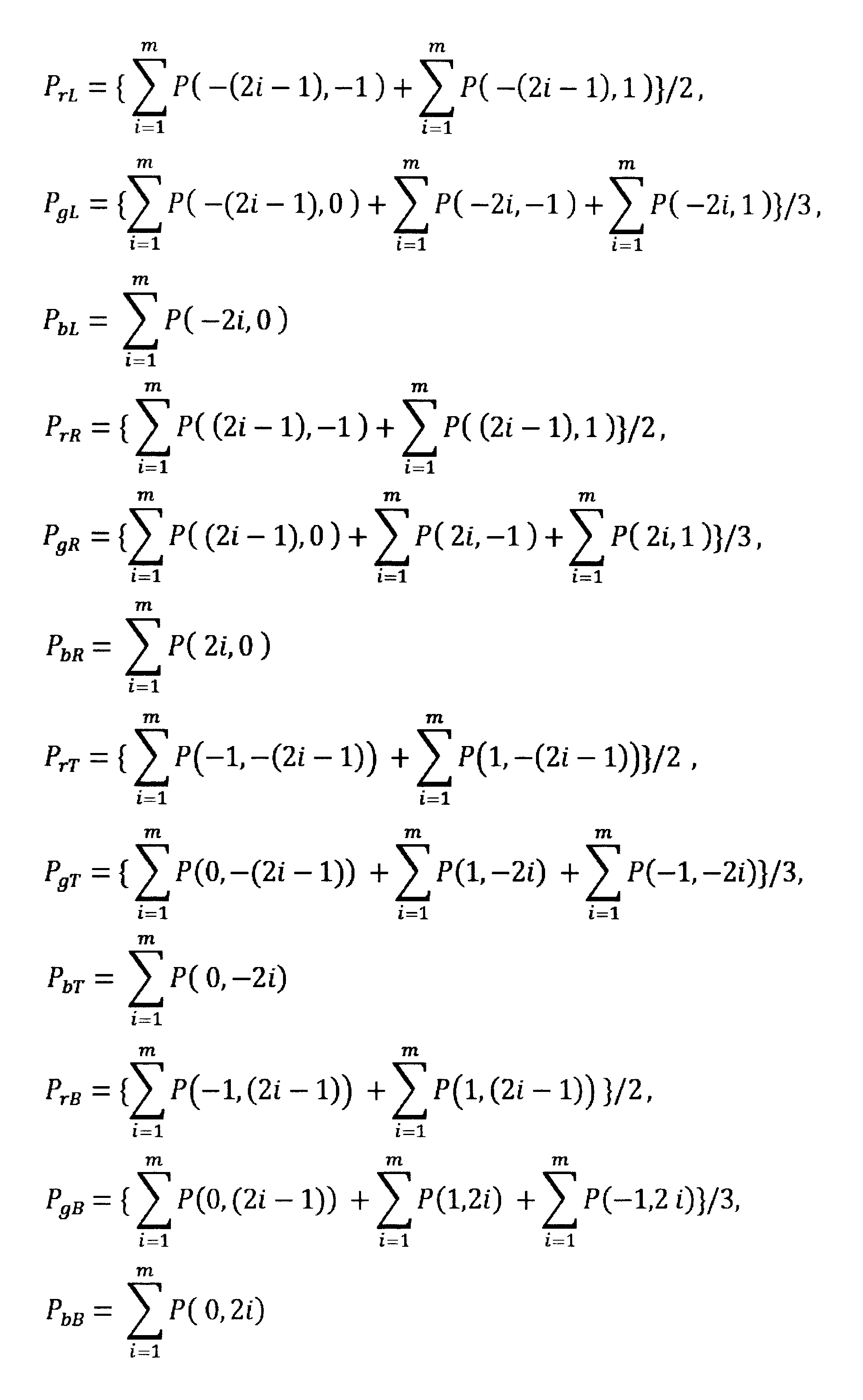

図17に示されるように、注目画素がGR(斜線部分)である場合には、数6及び数7に示される数式により合計画素値が算出される。


図18に示されるように、注目画素がGB(斜線部分)である場合には、数8及び数9に示される数式により合計画素値が算出される。
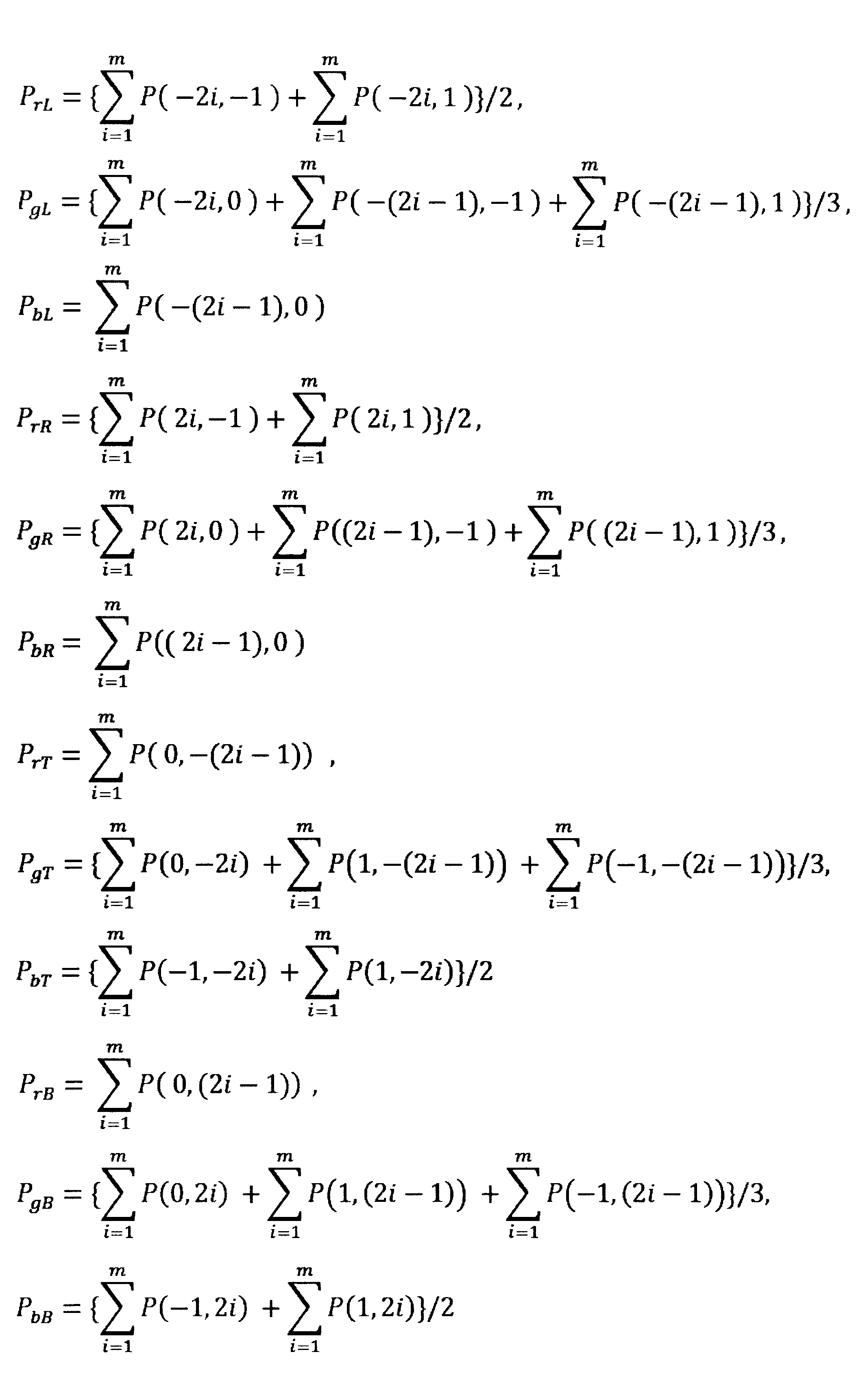
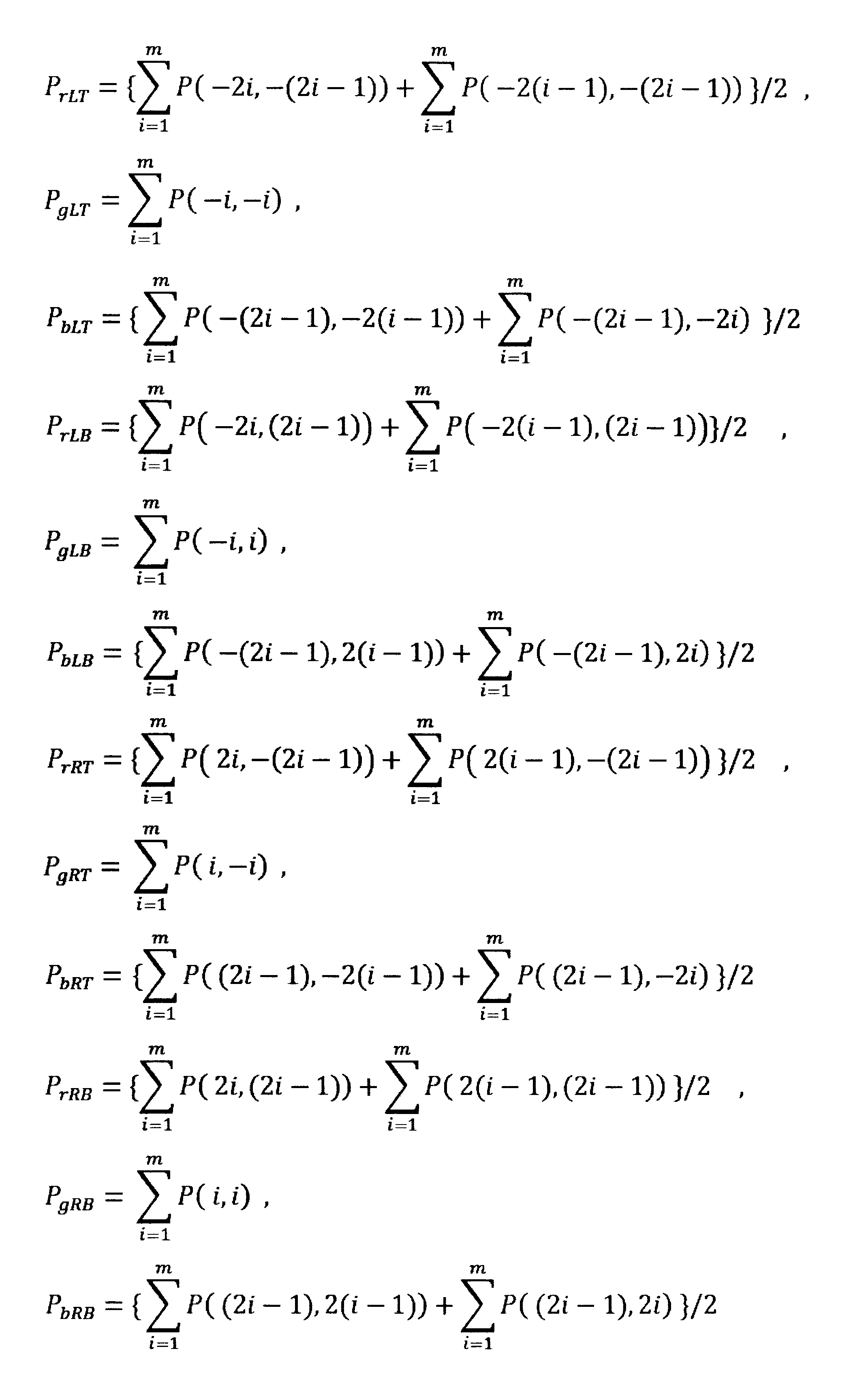
このようにすることで、同時化されていない画像に対しても軸上色収差の発生起点を検出することができ、検出時に同時化のための補間エラーの影響をなくすことができる。
本実施形態に係る画像処理装置1は、放送用据え置き型カメラ、ENGカメラ、民生用ハンディカメラ、デジタルカメラ等の製品に搭載して使用される。また、動画を扱う画像信号補正プログラム(CGプログラム)や画像編集装置等にも用いることができる。また、本実施形態に係る画像処理方法をコンピュータ(例えば、パーソナルコンピュータ)に実行させる画像処理プログラムとして用いることもできる。
本実施形態に係る画像処理装置1は、放送用据え置き型カメラ、ENGカメラ、民生用ハンディカメラ、デジタルカメラ等の製品に搭載して使用される。また、動画を扱う画像信号補正プログラム(CGプログラム)や画像編集装置等にも用いることができる。また、本実施形態に係る画像処理方法をコンピュータ(例えば、パーソナルコンピュータ)に実行させる画像処理プログラムとして用いることもできる。
2 領域抽出部
3 軸上色収差補正量算出部
4 収差補正部
10 合計画素値算出部
11 発生起点検出部
12 領域判定部
15 色空間情報算出部
16 色空間差分算出部
17 補正量算出部
3 軸上色収差補正量算出部
4 収差補正部
10 合計画素値算出部
11 発生起点検出部
12 領域判定部
15 色空間情報算出部
16 色空間差分算出部
17 補正量算出部
Claims (28)
- 入力画像中の注目画素を含み一列に配列する複数の画素について、該注目画素を挟んで一方向及び他方向に配列する画素の画素値を夫々色毎に合計する合計画素値算出部と、
該合計画素値算出部による算出結果又は前記注目画素の画素値の少なくとも一方に基づいて、前記注目画素が軸上色収差の発生起点であるか否かを判定し、発生起点を検出する発生起点検出部と、
前記発生起点として検出された注目画素を中心とする所定の周辺領域を軸上色収差領域と判定する領域判定部と、
前記発生起点として検出された前記注目画素に対し、前記合計画素値算出部による算出結果に基づいて、前記一方向及び前記他方向について特定色空間上の色空間情報を夫々算出する色空間情報算出部と、
該色空間情報算出部により算出された前記一方向の色空間情報と前記他方向の色空間情報との差分を算出する色空間差分算出部と、
該色空間差分算出部により算出された差分に応じて軸上色収差補正の補正量を算出する補正量算出部と、
前記軸上色収差領域について前記補正量を用いて補正する補正部と、
を備える画像処理装置。 - 前記色空間情報算出部が、特定色空間上の色空間情報として、色の角度に関する情報、色の強度に関する情報、及び色の明るさに関する情報の少なくとも1つを算出し、
前記色空間差分算出部が、前記色空間情報算出部による算出結果に基づいて、前記一方向の色空間情報と前記他方向の色空間情報との差分として、前記色の角度の差分、前記色の強度の差分、及び前記色の明るさの差分のうち少なくとも1つを算出し、
前記補正量算出部が、前記色空間差分算出部による算出結果に基づいて軸上色収差補正の補正量を算出する請求項1記載の画像処理装置。 - 前記補正量算出部が、前記色の角度の差分が180度に近いほど大きな補正量を算出し、180度から離れている程小さな補正量を算出する請求項2記載の画像処理装置。
- 前記補正量算出部が、前記色の強度の差分の絶対値が大きいほど大きな補正量を算出し、絶対値が小さいほど小さな補正量を算出する請求項2記載の画像処理装置。
- 前記補正量算出部が、前記色の明るさの差分の絶対値が大きいほど大きな補正量を算出し、絶対値が小さいほど小さな補正量を算出する請求項2記載の画像処理装置。
- 前記補正量算出部が、前記色の角度が前記一方向と前記他方向で同方向となる補正量を算出する請求項2記載の画像処理装置。
- 前記補正量算出部が、前記色の強度が前記一方向と前記他方向とで同一となる補正量を算出する請求項2記載の画像処理装置。
- 前記補正量算出部が、前記色の明るさが前記一方向と前記他方向とで同一となる補正量を算出する請求項2記載の画像処理装置。
- 前記特定色空間が、HSV空間である請求項1乃至請求項7の何れか1項記載の画像処理装置。
- 前記特定色空間が、L*a*b*空間である請求項1乃至請求項7の何れか1項記載の画像処理装置。
- 前記発生起点検出部が、前記注目画素の画素値が所定の閾値よりも大きい場合、又は、前記合計画素値算出部により算出された前記一方向に配列している画素のGの画素値の合計とRの画素値の合計との大小関係が、前記他方向に配列している画素のGの画素値の合計とRの画素値の合計との大小関係と逆である場合、若しくは、前記一方向に配列している画素のGの画素値の合計とBの画素値の合計との大小関係が、前記他方向に配列している画素のGの画素値の合計とBの画素値の合計との大小関係と逆である場合に、前記注目画素を軸上色収差の発生起点として検出する請求項1乃至請求項10の何れか1項記載の画像処理装置。
- 前記発生起点検出部が、以下の条件式を満足する場合に、前記注目画素を軸上色収差の発生起点であると判定する請求項1から請求項10の何れか1項記載の画像処理装置。
PgD1>PrD1
PgD2<PrD2
ここで、PgD1は前記注目画素から前記一方向に配列している画素のGの画素値の合計、PgD2は前記注目画素から前記他方向に配列している画素のGの画素値の合計、PrD1は前記注目画素から前記一方向に配列している画素のRの画素値の合計、PrD2は前記注目画素から前記他方向に配列している画素のRの画素値の合計である。 - 前記発生起点検出部が、以下の条件式を満足する場合に、前記注目画素を軸上色収差の発生起点であると判定する請求項1から請求項10の何れか1項記載の画像処理装置。
PgD1>PbD1
PgD2<PbD2
ここで、
PgD1は前記注目画素から前記一方向に配列している画素のGの画素値の合計、PgD2は前記注目画素から前記他方向に配列している画素のGの画素値の合計、PbD1は前記注目画素から前記一方向に配列している画素のBの画素値の合計、PbD2は前記注目画素から前記他方向に配列している画素のBの画素値の合計である。 - 前記発生起点検出部が、以下の条件式を満足する場合に、前記注目画素を軸上色収差の発生起点であると判定する請求項1から請求項10の何れか1項記載の画像処理装置。
PgD1>PrD1
PgD2<PrD2
PgD2<PbD2
ここで、
PgD1は前記注目画素から前記一方向に配列している画素のGの画素値の合計、PgD2は前記注目画素から前記他方向に配列している画素のGの画素値の合計、PrD1は前記注目画素から前記一方向に配列している画素のRの画素値の合計、PrD2は前記注目画素から前記他方向に配列している画素のRの画素値の合計、PbD2は前記注目画素から前記他方向に配列している画素のBの画素値の合計である。 - 前記発生起点検出部が、以下の条件式を満足する場合に、前記注目画素を軸上色収差の発生起点であると判定する請求項1から請求項10の何れか1項記載の画像処理装置。
PgD1>PbD1
PgD2<PrD2
PgD2<PbD2
ここで、PgD1は前記注目画素から前記一方向に配列している画素のGの画素値の合計、PgD2は前記注目画素から前記他方向に配列している画素のGの画素値の合計、PrD2は前記注目画素から前記他方向に配列している画素のRの画素値の合計、PbD1は前記注目画素から前記一方向に配列している画素のBの画素値の合計、PbD2は前記注目画素から前記他方向に配列している画素のBの画素値の合計である。 - 前記発生起点検出部が、以下の条件式を満足する場合に、前記注目画素を軸上色収差の発生起点であると判定する請求項1から請求項10の何れか1項記載の画像処理装置。
PgD1>PrD1
PgD1>PbD1
PgD2<PrD2
ここで、PgD1は前記注目画素から前記一方向に配列している画素のGの画素値の合計、PgD2は前記注目画素から前記他方向に配列している画素のGの画素値の合計、PrD1は前記注目画素から前記一方向に配列している画素のRの画素値の合計、PrD2は前記注目画素から前記他方向に配列している画素のRの画素値の合計、PbD1は前記注目画素から前記一方向に配列している画素のBの画素値の合計、である。 - 前記発生起点検出部が、以下の条件式を満足する場合に、前記注目画素を軸上色収差の発生起点であると判定する請求項1から請求項10の何れか1項記載の画像処理装置。
PgD1>PrD1
PgD1>PbD1
PgD2<PbD2
ここで、PgD1は前記注目画素から前記一方向に配列している画素のGの画素値の合計、PgD2は前記注目画素から前記他方向に配列している画素のGの画素値の合計、PrD1は前記注目画素から前記一方向に配列している画素のRの画素値の合計、PbD1は前記注目画素から前記一方向に配列している画素のBの画素値の合計、PbD2は前記注目画素から前記他方向に配列している画素のBの画素値の合計
である。 - 前記発生起点検出部が、以下の条件式を満足する場合に、前記注目画素を軸上色収差の発生起点であると判定する請求項1から請求項10の何れか1項記載の画像処理装置。
PgD1+THR1>PrD1
PgD2--THR2<PrD2
PgD1+THB1>PbD1
PgD2--THB2<PbD2
ここで、PgD1は前記注目画素から前記一方向に配列している画素のGの画素値の合計、PgD2は前記注目画素から前記他方向に配列している画素のGの画素値の合計、PrD1は前記注目画素から前記一方向に配列している画素のRの画素値の合計、PrD2は前記注目画素から前記他方向に配列している画素のRの画素値の合計、PbD1は前記注目画素から前記一方向に配列している画素のBの画素値の合計、PbD2は前記注目画素から前記他方向に配列している画素のBの画素値の合計、THR1,THR2,THB1,THB2は任意の定数である。 - 前記発生起点検出部が、以下の条件式を満足する場合に、前記注目画素を軸上色収差の発生起点であると判定する請求項1から請求項10の何れか1項記載の画像処理装置。
PgD1+THR>PrD1
PgD2+THR<PrD2
PgD1+THB>PbD1
PgD2+THB<PbD2
ここで、PgD1は前記注目画素から前記一方向に配列している画素のGの画素値の合計、PgD2は前記注目画素から前記他方向に配列している画素のGの画素値の合計、PrD1は前記注目画素から前記一方向に配列している画素のRの画素値の合計、PrD2は前記注目画素から前記他方向に配列している画素のRの画素値の合計、PbD1は前記注目画素から前記一方向に配列している画素のBの画素値の合計、PbD2は前記注目画素から前記他方向に配列している画素のBの画素値の合計、THR,THBは任意の定数である。 - 前記発生起点検出部が、以下の条件式を満足する場合に、前記注目画素を軸上色収差の発生起点であると判定する請求項1から請求項10の何れか1項記載の画像処理装置。
PgD1>PrD1×KR
PgD2<PrD2×KR
PgD1>PbD1×KB
PgD2<PbD2×KB
ここで、PgD1は前記注目画素から前記一方向に配列している画素のGの画素値の合計、PgD2は前記注目画素から前記他方向に配列している画素のGの画素値の合計、PrD1は前記注目画素から前記一方向に配列している画素のRの画素値の合計、PrD2は前記注目画素から前記他方向に配列している画素のRの画素値の合計、PbD1は前記注目画素から前記一方向に配列している画素のBの画素値の合計、PbD2は前記注目画素から前記他方向に配列している画素のBの画素値の合計、KR,KBは任意の定数である。 - 前記画像が、各画素にRGB全ての画素値を有する請求項1から20の何れか1項記載の画像処理装置。
- 前記画像が、各画素においてRGBの少なくとも1つの画素値が欠落した画素値を有する請求項1から請求項20の何れか1項記載の画像処理装置。
- 入力画像中の注目画素を含み一列に配列する複数の画素について、該注目画素を挟んで一方向及び他方向に配列する画素の画素値を夫々色毎に合計する合計画素値算出ステップと、
該合計画素値算出ステップにおける算出結果又は前記注目画素の画素値の少なくとも一方に基づいて、前記注目画素を軸上色収差の発生起点として検出する発生起点検出ステップと、
前記発生起点として検出された注目画素を中心とする所定の周辺領域を軸上色収差領域と判定する領域判定ステップと、
前記発生起点として検出された前記注目画素に対し、前記合計画素値算出ステップにおける算出結果に基づいて、前記一方向及び前記他方向について特定色空間上の色空間情報を夫々算出する色空間情報算出ステップと、
該色空間情報算出ステップにおいて算出された前記一方向の色空間情報と前記他方向の色空間情報との差分を算出する色空間差分算出ステップと、
該色空間差分算出ステップにおいて算出された差分に応じて軸上色収差補正の補正量を算出する補正量算出ステップと、
前記軸上色収差領域について前記補正量を用いて補正する補正ステップと、
を備える画像処理方法。 - 前記色空間情報算出ステップにおいて、特定色空間上の色空間情報として、色の角度に関する情報、色の強度に関する情報、及び色の明るさに関する情報の少なくとも1つを算出し、
前記色空間差分算出ステップにおいて、前記色空間情報算出ステップによる算出結果に基づいて、前記一方向の色空間情報と前記他方向の色空間情報との差分として、前記色の角度の差分、前記色の強度の差分、及び前記色の明るさの差分のうち少なくとも1つを算出し、
前記補正量算出ステップにおいて、前記色空間差分算出ステップによる算出結果に基づいて軸上色収差補正の補正量を算出する請求項23記載の画像処理方法。 - 前記発生起点検出ステップにおいて、前記注目画素の画素値が所定の閾値よりも大きい場合、又は、前記合計画素値算出部により算出された前記一方向に配列している画素のGの画素値の合計とRの画素値の合計との大小関係が、前記他方向に配列している画素のGの画素値の合計とRの画素値の合計との大小関係と逆である場合、若しくは、前記一方向に配列している画素のGの画素値の合計とBの画素値の合計との大小関係が、前記他方向に配列している画素のGの画素値の合計とBの画素値の合計との大小関係と逆である場合に、前記注目画素を軸上色収差の発生起点として検出する請求項23又は請求項24記載の画像処理方法。
- 入力画像中の注目画素を含み一列に配列する複数の画素について、該注目画素を挟んで一方向及び他方向に配列する画素の画素値を夫々色毎に合計する合計画素値算出ステップと、
該合計画素値算出ステップにおける算出結果又は前記注目画素の画素値の少なくとも一方に基づいて、前記注目画素を軸上色収差の発生起点として検出する発生起点検出ステップと、
前記発生起点として検出された注目画素を中心とする所定の周辺領域を軸上色収差領域と判定する領域判定ステップと、
前記発生起点として検出された前記注目画素に対し、前記合計画素値算出ステップにおける算出結果に基づいて、前記一方向及び前記他方向について特定色空間上の色空間情報を夫々算出する色空間情報算出ステップと、
該色空間情報算出ステップにおいて算出された前記一方向の色空間情報と前記他方向の色空間情報との差分を算出する色空間差分算出ステップと、
該色空間差分算出ステップにおいて算出された差分に応じて軸上色収差補正の補正量を算出する補正量算出ステップと、
前記軸上色収差領域について前記補正量を用いて補正する補正ステップと、
をコンピュータに実行させる画像処理プログラム。 - 前記コンピュータが、
前記色空間情報算出ステップにおいて、特定色空間上の色空間情報として、色の角度に関する情報、色の強度に関する情報、及び色の明るさに関する情報の少なくとも1つを算出し、
前記色空間差分算出ステップにおいて、前記色空間情報算出ステップによる算出結果に基づいて、前記一方向の色空間情報と前記他方向の色空間情報との差分として、前記色の角度の差分、前記色の強度の差分、及び前記色の明るさの差分のうち少なくとも1つを算出し、
前記補正量算出ステップにおいて、前記色空間差分算出ステップによる算出結果に基づいて軸上色収差補正の補正量を算出する請求項27記載の画像処理プログラム。 - 前記コンピュータが、
前記発生起点検出ステップにおいて、前記注目画素の画素値が所定の閾値よりも大きい場合、又は、前記合計画素値算出部により算出された前記一方向に配列している画素のGの画素値の合計とRの画素値の合計との大小関係が、前記他方向に配列している画素のGの画素値の合計とRの画素値の合計との大小関係と逆である場合、若しくは、前記一方向に配列している画素のGの画素値の合計とBの画素値の合計との大小関係が、前記他方向に配列している画素のGの画素値の合計とBの画素値の合計との大小関係と逆である場合に、前記注目画素を軸上色収差の発生起点として検出する請求項26又は請求項27記載の画像処理プログラム。
Priority Applications (4)
| Application Number | Priority Date | Filing Date | Title |
|---|---|---|---|
| PCT/JP2015/063540 WO2016181476A1 (ja) | 2015-05-12 | 2015-05-12 | 画像処理装置、画像処理方法及び画像処理プログラム |
| CN201580079861.6A CN107534758B (zh) | 2015-05-12 | 2015-05-12 | 图像处理装置、图像处理方法和记录介质 |
| JP2017517499A JP6633624B2 (ja) | 2015-05-12 | 2015-05-12 | 画像処理装置、画像処理方法及び画像処理プログラム |
| US15/804,752 US10659738B2 (en) | 2015-05-12 | 2017-11-06 | Image processing apparatus, image processing method, and image processing program product |
Applications Claiming Priority (1)
| Application Number | Priority Date | Filing Date | Title |
|---|---|---|---|
| PCT/JP2015/063540 WO2016181476A1 (ja) | 2015-05-12 | 2015-05-12 | 画像処理装置、画像処理方法及び画像処理プログラム |
Related Child Applications (1)
| Application Number | Title | Priority Date | Filing Date |
|---|---|---|---|
| US15/804,752 Continuation US10659738B2 (en) | 2015-05-12 | 2017-11-06 | Image processing apparatus, image processing method, and image processing program product |
Publications (1)
| Publication Number | Publication Date |
|---|---|
| WO2016181476A1 true WO2016181476A1 (ja) | 2016-11-17 |
Family
ID=57247848
Family Applications (1)
| Application Number | Title | Priority Date | Filing Date |
|---|---|---|---|
| PCT/JP2015/063540 Ceased WO2016181476A1 (ja) | 2015-05-12 | 2015-05-12 | 画像処理装置、画像処理方法及び画像処理プログラム |
Country Status (4)
| Country | Link |
|---|---|
| US (1) | US10659738B2 (ja) |
| JP (1) | JP6633624B2 (ja) |
| CN (1) | CN107534758B (ja) |
| WO (1) | WO2016181476A1 (ja) |
Families Citing this family (6)
| Publication number | Priority date | Publication date | Assignee | Title |
|---|---|---|---|---|
| CN106341670B (zh) | 2016-11-29 | 2017-09-22 | 广东欧珀移动通信有限公司 | 控制方法、控制装置及电子装置 |
| CN106504218B (zh) | 2016-11-29 | 2019-03-12 | Oppo广东移动通信有限公司 | 控制方法、控制装置及电子装置 |
| CN106454054B (zh) | 2016-11-29 | 2019-03-19 | Oppo广东移动通信有限公司 | 控制方法、控制装置及电子装置 |
| CN106454288B (zh) | 2016-11-29 | 2018-01-19 | 广东欧珀移动通信有限公司 | 控制方法、控制装置、成像装置及电子装置 |
| GB2568261B (en) | 2017-11-08 | 2022-01-26 | Displaylink Uk Ltd | System and method for presenting data at variable quality |
| US11442266B1 (en) * | 2019-09-09 | 2022-09-13 | Apple Inc. | Method and device for correcting chromatic aberration in multiple bands |
Citations (3)
| Publication number | Priority date | Publication date | Assignee | Title |
|---|---|---|---|---|
| WO2007007878A1 (ja) * | 2005-07-14 | 2007-01-18 | Nikon Corporation | 画像処理装置および画像処理方法 |
| US20120106841A1 (en) * | 2010-11-03 | 2012-05-03 | Zoran Corporation | System and method for providing multi resolution purple fringing detection and correction |
| JP2013172402A (ja) * | 2012-02-22 | 2013-09-02 | Nikon Corp | 画像処理装置、撮像装置および画像処理プログラム |
Family Cites Families (14)
| Publication number | Priority date | Publication date | Assignee | Title |
|---|---|---|---|---|
| JP4539278B2 (ja) | 2004-10-13 | 2010-09-08 | ソニー株式会社 | 画像処理装置、および画像処理方法、並びにコンピュータ・プログラム |
| JP4487902B2 (ja) | 2005-11-09 | 2010-06-23 | ソニー株式会社 | 画像処理装置および方法、並びにプログラム |
| US7577292B2 (en) | 2005-12-30 | 2009-08-18 | Microsoft Corporation | Automatic removal of purple fringing from images |
| JP4192975B2 (ja) * | 2006-07-26 | 2008-12-10 | ソニー株式会社 | 画像処理装置および方法、プログラム並びに記録媒体 |
| JP5200645B2 (ja) | 2008-04-24 | 2013-06-05 | 株式会社ニコン | 画像処理装置、撮像装置、画像処理方法およびプログラム |
| JP5163733B2 (ja) | 2010-06-17 | 2013-03-13 | 株式会社ニコン | 撮像装置、および焦点判定プログラム |
| US8958009B2 (en) | 2010-01-12 | 2015-02-17 | Nikon Corporation | Image-capturing device |
| JP5324508B2 (ja) | 2010-03-26 | 2013-10-23 | 富士フイルム株式会社 | 画像処理装置および方法,ならびに画像処理プログラム |
| JP5552956B2 (ja) | 2010-08-12 | 2014-07-16 | 株式会社ニコン | 画像処理装置、画像処理方法およびプログラム |
| JP5840008B2 (ja) | 2011-02-21 | 2016-01-06 | キヤノン株式会社 | 画像処理装置、画像処理方法およびプログラム |
| JP2012209709A (ja) * | 2011-03-29 | 2012-10-25 | Sony Corp | 画像処理装置および方法、記録媒体並びにプログラム |
| JP5847471B2 (ja) | 2011-07-20 | 2016-01-20 | キヤノン株式会社 | 画像処理装置、撮像装置、画像処理方法および画像処理プログラム |
| JP2014086932A (ja) | 2012-10-25 | 2014-05-12 | Sony Corp | 画像処理装置、画像処理方法、および画像処理プログラム |
| WO2016084223A1 (ja) | 2014-11-28 | 2016-06-02 | オリンパス株式会社 | 画像処理装置、画像処理方法および画像処理プログラム |
-
2015
- 2015-05-12 WO PCT/JP2015/063540 patent/WO2016181476A1/ja not_active Ceased
- 2015-05-12 CN CN201580079861.6A patent/CN107534758B/zh active Active
- 2015-05-12 JP JP2017517499A patent/JP6633624B2/ja active Active
-
2017
- 2017-11-06 US US15/804,752 patent/US10659738B2/en active Active
Patent Citations (3)
| Publication number | Priority date | Publication date | Assignee | Title |
|---|---|---|---|---|
| WO2007007878A1 (ja) * | 2005-07-14 | 2007-01-18 | Nikon Corporation | 画像処理装置および画像処理方法 |
| US20120106841A1 (en) * | 2010-11-03 | 2012-05-03 | Zoran Corporation | System and method for providing multi resolution purple fringing detection and correction |
| JP2013172402A (ja) * | 2012-02-22 | 2013-09-02 | Nikon Corp | 画像処理装置、撮像装置および画像処理プログラム |
Also Published As
| Publication number | Publication date |
|---|---|
| US20180077392A1 (en) | 2018-03-15 |
| CN107534758B (zh) | 2019-05-28 |
| US10659738B2 (en) | 2020-05-19 |
| JP6633624B2 (ja) | 2020-01-22 |
| CN107534758A (zh) | 2018-01-02 |
| JPWO2016181476A1 (ja) | 2018-03-01 |
Similar Documents
| Publication | Publication Date | Title |
|---|---|---|
| JP6633624B2 (ja) | 画像処理装置、画像処理方法及び画像処理プログラム | |
| JP5314357B2 (ja) | 映像の色収差の補正方法および装置 | |
| KR102441209B1 (ko) | Avm 시스템 어라운드 영상 정합성 평가방법 및 장치 | |
| US20100166305A1 (en) | Method for detecting and correcting chromatic aberration, and apparatus and method for processing image using the same | |
| JP6600936B2 (ja) | 画像処理装置、画像処理方法、画像処理システム、プログラム、及び記録媒体 | |
| CN102685511B (zh) | 图像处理设备和图像处理方法 | |
| JP2014086932A (ja) | 画像処理装置、画像処理方法、および画像処理プログラム | |
| JP2015211319A5 (ja) | 画像処理装置、画像処理方法、およびプログラム | |
| CN108282647B (zh) | 色彩校正方法及装置、计算机可读存储介质、终端 | |
| JP2011095061A5 (ja) | ||
| JP2019168930A5 (ja) | ||
| JP6441379B2 (ja) | 画像処理装置、画像処理方法および画像処理プログラム | |
| JP5718138B2 (ja) | 画像信号処理装置及びプログラム | |
| JP6415093B2 (ja) | 画像処理装置、画像処理方法、及びプログラム | |
| JP6415094B2 (ja) | 画像処理装置、撮像装置、画像処理方法およびプログラム | |
| JP2015211343A5 (ja) | ||
| KR102015587B1 (ko) | 결함 화소 검출 장치, 결함 화소 검출 방법 및 프로그램 | |
| JP5252247B2 (ja) | ターゲット位置決定装置 | |
| US11410274B2 (en) | Information processing device and program | |
| US8068145B1 (en) | Method, systems, and computer program product for demosaicing images | |
| KR102016630B1 (ko) | 채색 체스보드를 이용한 컬러 캘리브레이션 기반의 svm 영상 생성 방법 | |
| JP6552248B2 (ja) | 画像処理装置及び方法、撮像装置、並びにプログラム | |
| JP6595886B2 (ja) | 変色判定装置及び変色判定方法 | |
| JP2009296471A (ja) | 映像信号処理装置、撮像装置及び映像信号処理方法 | |
| JP2017050691A5 (ja) |
Legal Events
| Date | Code | Title | Description |
|---|---|---|---|
| 121 | Ep: the epo has been informed by wipo that ep was designated in this application |
Ref document number: 15891802 Country of ref document: EP Kind code of ref document: A1 |
|
| ENP | Entry into the national phase |
Ref document number: 2017517499 Country of ref document: JP Kind code of ref document: A |
|
| NENP | Non-entry into the national phase |
Ref country code: DE |
|
| 122 | Ep: pct application non-entry in european phase |
Ref document number: 15891802 Country of ref document: EP Kind code of ref document: A1 |