WO2016181455A1 - シミュレーション再現装置、シミュレーション再現方法およびシミュレーション再現プログラム - Google Patents
シミュレーション再現装置、シミュレーション再現方法およびシミュレーション再現プログラム Download PDFInfo
- Publication number
- WO2016181455A1 WO2016181455A1 PCT/JP2015/063470 JP2015063470W WO2016181455A1 WO 2016181455 A1 WO2016181455 A1 WO 2016181455A1 JP 2015063470 W JP2015063470 W JP 2015063470W WO 2016181455 A1 WO2016181455 A1 WO 2016181455A1
- Authority
- WO
- WIPO (PCT)
- Prior art keywords
- time
- reproduction
- display
- trace data
- state
- Prior art date
Links
Images


Classifications
-
- G—PHYSICS
- G06—COMPUTING; CALCULATING OR COUNTING
- G06F—ELECTRIC DIGITAL DATA PROCESSING
- G06F11/00—Error detection; Error correction; Monitoring
- G06F11/28—Error detection; Error correction; Monitoring by checking the correct order of processing
-
- G—PHYSICS
- G06—COMPUTING; CALCULATING OR COUNTING
- G06F—ELECTRIC DIGITAL DATA PROCESSING
- G06F11/00—Error detection; Error correction; Monitoring
- G06F11/30—Monitoring
- G06F11/34—Recording or statistical evaluation of computer activity, e.g. of down time, of input/output operation ; Recording or statistical evaluation of user activity, e.g. usability assessment
- G06F11/3457—Performance evaluation by simulation
- G06F11/3461—Trace driven simulation
-
- G—PHYSICS
- G06—COMPUTING; CALCULATING OR COUNTING
- G06F—ELECTRIC DIGITAL DATA PROCESSING
- G06F11/00—Error detection; Error correction; Monitoring
- G06F11/36—Preventing errors by testing or debugging software
- G06F11/3604—Software analysis for verifying properties of programs
- G06F11/3612—Software analysis for verifying properties of programs by runtime analysis
-
- G—PHYSICS
- G06—COMPUTING; CALCULATING OR COUNTING
- G06F—ELECTRIC DIGITAL DATA PROCESSING
- G06F11/00—Error detection; Error correction; Monitoring
- G06F11/36—Preventing errors by testing or debugging software
- G06F11/362—Software debugging
- G06F11/3636—Software debugging by tracing the execution of the program
-
- G—PHYSICS
- G06—COMPUTING; CALCULATING OR COUNTING
- G06F—ELECTRIC DIGITAL DATA PROCESSING
- G06F11/00—Error detection; Error correction; Monitoring
- G06F11/36—Preventing errors by testing or debugging software
- G06F11/362—Software debugging
- G06F11/3648—Software debugging using additional hardware
-
- G—PHYSICS
- G06—COMPUTING; CALCULATING OR COUNTING
- G06F—ELECTRIC DIGITAL DATA PROCESSING
- G06F11/00—Error detection; Error correction; Monitoring
- G06F11/36—Preventing errors by testing or debugging software
- G06F11/3664—Environments for testing or debugging software
-
- G—PHYSICS
- G06—COMPUTING; CALCULATING OR COUNTING
- G06F—ELECTRIC DIGITAL DATA PROCESSING
- G06F30/00—Computer-aided design [CAD]
- G06F30/20—Design optimisation, verification or simulation
-
- G—PHYSICS
- G05—CONTROLLING; REGULATING
- G05B—CONTROL OR REGULATING SYSTEMS IN GENERAL; FUNCTIONAL ELEMENTS OF SUCH SYSTEMS; MONITORING OR TESTING ARRANGEMENTS FOR SUCH SYSTEMS OR ELEMENTS
- G05B17/00—Systems involving the use of models or simulators of said systems
- G05B17/02—Systems involving the use of models or simulators of said systems electric
Definitions
- the present invention relates to a technique for reproducing a simulated operation of a target with a graphic display.
- the software simulator can display the state of the peripheral device or the state of the input / output terminal of the microcomputer in a graphic form. For example, the software simulator graphically displays lighting and extinguishing of LEDs as the state of the peripheral device. Further, the software simulator displays the signal value of the signal input / output to / from the input / output terminal in a graphic form as the state of the input / output terminal. Therefore, the user can visually recognize how the state of the peripheral device or the state of the input / output terminal of the microcomputer changes during execution of the simulation by the software simulator.
- Patent Document 1 discloses such a simulator.
- the simulator disclosed in Patent Document 1 operates as follows.
- the simulator records, as trace data, an occurrence time when a state change occurs during execution of the simulation and an updated value that is a state value after the change.
- the simulator converts the generation time of the trace data into a reproduction display time that reproduces and displays the change in the state.
- the simulator then reads the trace data and displays the change in state in a graphic at the reproduction display time. Thereby, the simulator can reproduce the change of the state using the trace data without executing the simulation again.
- the simulator also changes the speed at which the change in state is reproduced by converting the time of occurrence to the reproduction display time using the speed ratio of the time elapsed speed at the time of reproduction to the time elapsed speed at the time of simulation. Can do.
- the simulator can reproduce the state change at high speed.
- the conventional simulator cannot reproduce the state change in the reverse order of the passage of time. Therefore, the conventional simulator is inconvenient in the following points.
- the user wants to check a change in state while going back to the past from the time when the user noticed the illegal operation in order to find the cause of the illegal operation.
- the conventional simulator cannot reproduce the change in state in the reverse order of the passage of time, the user checks the state change in the order of the passage of time from the time of starting the simulation, I have to find it. As a result, it takes time to find the cause of the illegal operation.
- the conventional simulator cannot change the speed at which the state change is reproduced while the state change is being reproduced. Therefore, the user overlooks a change in state if the speed of reproduction is fast, and it takes time to check the change of state if the speed of reproduction is slow. For example, when the LED being reproduced is blinking at a high speed, the user wants to increase the time interval at which the LED blinks in order to ensure the viewing time. However, since the conventional simulator cannot change the speed of reproduction during reproduction, the time interval at which the LEDs blink cannot be increased. Further, when the lighting state of the LED being reproduced does not change, the user wants to shorten the time during which the LED whose lighting state does not change is displayed for the efficiency of the confirmation work. However, since the conventional simulator cannot change the speed of reproduction during reproduction, the time during which an LED whose lighting state does not change cannot be shortened cannot be shortened.
- An object of the present invention is to make it possible to keep the time during which an object continues to be displayed without changing its state within the upper limit cycle when the simulated operation of the object is reproduced in a graphic display.
- the simulation reproduction apparatus of the present invention reproduces the simulated operation of the object with a graphic display.
- the simulation reproduction apparatus is One or more traces that are obtained by simulating the operation of the object, and include an occurrence time when the change of the state of the object occurs and a new state value indicating the state after the change of the state
- a storage unit for storing a trace file which is a file in which data is recorded;
- a reception unit that receives an upper limit cycle that is an upper limit of a length of time that the object continues to be displayed without changing its state;
- a trace data reading unit for reading the trace data from the trace file one by one; Interval between the new display time corresponding to the occurrence time included in the new trace data which is the trace data read this time and the old display time corresponding to the occurrence time included in the old trace data which is the trace data read last time Is longer than the upper limit cycle, the display unit changes the state of the graphically displayed target to a state indicated by the new state value included in the new trace data at a time de
- the time during which the target continues to be displayed without changing the state can be made within the upper limit cycle.
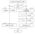
- FIG. 2 is a functional configuration diagram of a simulation reproduction device 100 according to Embodiment 1.
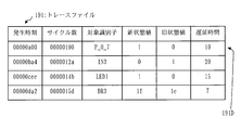
- FIG. FIG. 3 is a configuration diagram of a trace file 191 in the first embodiment.
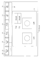
- FIG. 3 is a configuration diagram of a reproduction screen 200 in the first embodiment.
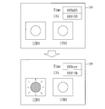
- FIG. 6 shows a change in the graphic display 210 according to the first embodiment.
- FIG. 6 is a diagram showing invalidation of a forward reproduction button 221 according to the first embodiment.
- 2 is a functional configuration diagram of a reproduction unit 110 according to Embodiment 1.
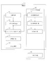
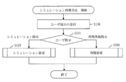
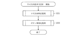
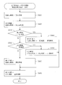
- FIG. 3 is a flowchart of a simulation reproduction method according to the first embodiment. 6 is a flowchart of simulation processing (S120) in the first embodiment. 5 is a flowchart of a reproduction process (S200) in the first embodiment.
- FIG. 5 is a flowchart of initialization processing (S210) in the first embodiment.
- 6 is a flowchart of non-direction processing (S220) in the first embodiment.
- FIG. 6 is a flowchart of button invalidation processing (S222) in the first embodiment.
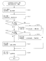
- 5 is a flowchart of forward direction reproduction processing (S240) in the first embodiment.
- FIG. 5 is a flowchart of reverse direction reproduction processing (S250) in the first embodiment.
- 6 is a flowchart of trace data reading processing (S252) according to the first embodiment.
- FIG. 6 is a flowchart of forward frame advance processing (S260) in the first embodiment.
- 5 is a flowchart of reverse frame advance processing (S270) in the first embodiment.
- FIG. 10 is a configuration diagram of a trace file 191 in the second embodiment.
- FIG. The hardware block diagram of the simulation reproduction apparatus 100 in embodiment.
- Embodiment 1 A simulation reproduction apparatus 100 that reproduces a simulated operation of an object with a graphic display will be described with reference to FIGS. 1 to 20.
- the simulation reproduction apparatus 100 includes a reception unit 101, a reproduction unit 110, a reproduction clock unit 102, a display unit 120, a simulation unit 180, and a storage unit 190.
- the receiving unit 101 receives a user instruction input to the simulation reproduction device 100 by a user who uses the simulation reproduction device 100.
- the user instruction includes a simulation instruction and a reproduction instruction.
- the simulation instruction is an instruction for simulating a target operation.
- the reproduction instruction is an instruction to reproduce the simulated operation of the object in a graphic display.
- the reproduction instructions include a reproduction start instruction, a forward direction reproduction instruction, a reverse direction reproduction instruction, a pause instruction, a forward frame advance instruction, a backward frame advance instruction, and a parameter setting instruction.
- the reproduction start instruction is an instruction to start reproduction of the target motion.
- the forward direction reproduction instruction is an instruction for performing forward direction reproduction to reproduce the target operation in time order.
- the reverse direction reproduction instruction is an instruction for performing reverse direction reproduction to reproduce the target motion in reverse order of time.
- the pause instruction is an instruction to pause reproduction of the target motion.
- the forward frame advance instruction is an instruction to perform forward frame advance in which the target state changes once in time order.
- the reverse frame advance instruction is an instruction to perform reverse frame advance in which the target state changes once in the reverse order of the time.
- the parameter setting instruction is an instruction to set a parameter used when reproducing the target operation.
- the parameter setting instruction includes an upper limit cycle setting instruction and a lower limit cycle setting instruction.
- the upper limit cycle setting instruction is an instruction for setting the upper limit period 192
- the lower limit cycle setting instruction is an instruction for setting the lower limit period 193.
- the upper limit cycle 192 is an upper limit of the length of time that the object continues to be displayed without changing its state.
- the initial value of the upper limit cycle 192 is a value representing the longest cycle.
- the lower limit cycle 193 is a lower limit of the length of time that the object continues to be displayed without changing its state.
- the initial value of the lower limit cycle 193 is a value representing the shortest cycle.
- the simulation unit 180 simulates the target operation by executing a simulation program, and generates a trace file 191. While the target motion is being simulated, the simulated target motion is displayed graphically on the simulation screen.
- the simulation screen is generated by the simulation screen display unit 122 of the display unit 120.
- the configuration of the trace file 191 will be described based on FIG.
- the trace file 191 is a file in which one or more trace data 191D is recorded.
- One line in the figure corresponds to one piece of trace data 191D.
- the trace data 191D includes an occurrence time, the number of cycles, a target identifier, a new state value, and an old state value.
- the occurrence time is the time when the change in the target state occurs.
- the cycle number is a value representing the generation time as a virtual clock count.
- a virtual clock is a clock of a virtual computer, and a virtual computer is a virtual computer on which an object operates.
- the occurrence time and the number of cycles have the following relationship.
- the target identifier identifies the target. Examples of objects are LEDs and peripheral devices.
- the new state value indicates the state of the target after the state of the target has changed.
- the old state value indicates the state of the object before the state of the object changes.
- One or more pieces of trace data 191D are recorded in the trace file 191 in order of time of occurrence.
- the reproduction unit 110 uses the trace file 191, the reproduction time 109, the upper limit cycle 192, the lower limit cycle 193, the initial state flag 194, and the operation impossibility information 195 in a graphic display.
- the reproduction time 109 is a time that reproduces the time of the time zone in which the target operation is simulated, and is acquired from the reproduction clock unit 102.
- the initial state flag 194 is a flag indicating whether or not the state of the target being reproduced is an initial state. A flag value indicating an initial state is set as an initial state value, and a flag value indicating a state other than the initial state is set as a non-initial state value.
- the operation impossibility information 195 is information indicating whether the target motion can be reproduced in the order of time and in the reverse order of the time.
- the reproduction clock unit 102 functions as a clock indicating the reproduction time 109.
- the reproduction time 109 is acquired from the reproduction unit 110, the display unit 120, and the simulation unit 180 as needed.
- the reproduction clock unit 102 advances the reproduction time 109 in time order.
- the reproduction clock unit 102 advances the reproduction time 109 in the reverse order.
- the display unit 120 includes a reproduction screen display unit 121 and a simulation screen display unit 122.
- the reproduction screen display unit 121 displays the reproduction screen 200 using the reproduction screen file 199 and the reproduction time 109.
- the reproduction screen file 199 is a file including images that constitute the reproduction screen 200.
- the reproduction screen 200 will be described with reference to FIG.
- the reproduction screen 200 includes a graphic display 210, a button widget 220, and a message area 230.
- the graphic display 210 is a graphic representing a change in the state of the simulated object.
- the graphic display 210 indicates the lighting states of the LEDs 1 and 2 for the LEDs 1 and 2.
- the graphic display 210 shows the reproduction time 109 and the number of clocks corresponding to the reproduction time 109.
- the time column in the figure shows the reproduction time 109, and the Clk column in the figure shows the number of clocks.
- the reproduction time 109 in the Time column and the number of clocks in the Clk column change with the reproduction time 109 of the reproduction clock unit 102. For example, when only LED 1 is turned on from the state where LED 1 and LED 2 are turned off, as shown in FIG. 4, the state of LED 1 changes from the turned off state to the turned on state.
- the button widget 220 includes a forward reproduction button 221, a backward reproduction button 222, a forward frame advance button 223, a backward frame advance button 224, an upper limit cycle button 225, and a lower limit cycle button 226.
- the forward reproduction button 221 is a button for reproducing the forward direction. When the forward reproduction button 221 is pressed, a forward reproduction instruction is accepted.
- the reverse direction reproduction button 222 is a button for reverse direction reproduction. When the reverse direction reproduction button 222 is pressed, a reverse direction reproduction instruction is accepted.
- the forward frame advance button 223 is a forward frame advance button. When the forward frame advance button 223 is pressed, a forward frame advance instruction is accepted.
- the reverse frame advance button 224 is a button for reverse frame advance.
- the upper limit cycle button 225 is a button for setting an upper limit cycle.
- the upper limit cycle button 225 is pressed, a dialog for designating the upper limit cycle 192 is displayed, and a setting instruction for the upper limit cycle 192 designated in the displayed dialog is accepted.
- the lower limit cycle button 226 is a button for setting a lower limit cycle. When the lower limit cycle button 226 is pressed, a dialog for specifying the lower limit cycle 193 is displayed, and a setting instruction for the lower limit cycle 193 specified in the displayed dialog is accepted.
- the reverse direction reproduction button 222 and the reverse direction frame advance button 224 are invalidated.
- the reverse direction reproduction button 222 and the reverse direction frame advance button 224 are invalidated, the reverse direction reproduction instruction and the reverse direction frame advance instruction are not accepted, and the reverse direction reproduction and the reverse direction frame advance are not performed.
- the operation impossibility information 195 indicates the forward direction as the operation impossibility direction
- the forward reproduction button 221 and the forward frame advance button 223 are invalidated.
- the forward reproduction button 221 and the forward frame advance button 223 are disabled, the forward reproduction instruction and the forward frame advance instruction are not accepted, and the forward reproduction and the forward frame advance are not performed.
- the display of the forward reproduction button 221 changes as shown in FIG. The same applies to the other buttons.
- the message area 230 is an area where a message is displayed. For example, when the invalidated forward direction reproduction button 221 is pressed, an error message indicating that the forward direction reproduction instruction is invalid is displayed in the message area 230.
- the simulation screen display unit 122 displays a simulation screen using the simulation screen file 189 and the reproduction time 109.
- the simulation screen file 189 is a file including images constituting the simulation screen.
- the simulation screen is a screen including a display corresponding to the graphic display 210 of the reproduction screen 200.
- the storage unit 190 stores data used, generated, or input / output by the simulation reproduction device 100.
- An example of data stored in the storage unit 190 is a trace file 191, an upper limit cycle 192, a lower limit cycle 193, an initial state flag 194, operation impossible information 195, a reproduction screen file 199, and a simulation screen file 189.
- the reproduction unit 110 includes an initialization unit 111, an impossible direction determination unit 112, a trace data reading unit 113, a display interval calculation unit 114, a waiting time calculation unit 115, and a time waiting unit 116. Furthermore, the reproduction unit 110 includes a cycle setting unit 117 and a reproduction control unit 119.
- the initialization unit 111 performs an initialization process for reproducing the target operation in a graphic display. Details of the initialization process will be described later.
- the unusable direction determination unit 112 performs unusable direction determination processing for determining a valid reproduction instruction and an invalid reproduction instruction based on the reference position of the trace file 191. Details of the unusable direction determination process will be described later.
- the trace data reading unit 113 reads the trace data 191D from the trace file 191.
- the trace data reading unit 113 reads the trace data 191D one by one in the order of time of occurrence.
- the trace data reading unit 113 reads the trace data 191D one by one in the reverse order of the generation time.
- the trace data reading unit 113 reads one trace data 191D in the order of time of occurrence.
- the trace data reading unit 113 reads one trace data 191D in the reverse order of the generation time.
- the trace data read this time is called new trace data.
- the time corresponding to the occurrence time included in the new trace data is called a new display time.
- the occurrence time included in the new trace data is the new display time.
- the new display time is the time that goes back the correction time from the occurrence time included in the new trace data.
- the correction time is a predetermined minute time.
- the previously read trace data is called old trace data.
- the time corresponding to the occurrence time included in the old trace data is called the old display time.
- the occurrence time included in the old trace data is the old display time.
- the time from the occurrence time included in the old trace data to the correction time is the old display time.
- the display interval calculation unit 114 calculates a display interval that is an interval between the new display time and the old display time.
- the display interval calculation unit 114 calculates an interval from the old display time to the new display time as the display interval.
- the display interval calculation unit 114 calculates an interval from the new display time to the old display time as the display interval.
- the waiting time calculation unit 115 calculates a waiting time until the target state is changed. When the interval between the new display time and the old display time is longer than the upper limit cycle 192, the wait time calculation unit 115 calculates the wait time using the old display time and the upper limit cycle 192. When the display interval calculated during the reproduction in the forward direction is longer than the upper limit cycle 192, the waiting time calculation unit 115 displays the reproduction time 109 indicated by the reproduction clock unit 102 and the time when the upper limit cycle 192 elapses from the old display time. Is calculated as a waiting time.
- the waiting time calculation unit 115 sets the interval between the reproduction time 109 indicated by the reproduction clock unit 102 and the time that goes back from the old display time to the upper limit cycle 192. Calculate as waiting time.
- the waiting time calculation unit 115 calculates the waiting time using the old display time and the lower limit cycle 193.
- the waiting time calculation unit 115 displays the reproduction time 109 indicated by the reproduction clock unit 102 and the time when the lower limit cycle 193 elapses from the old display time. Is calculated as a waiting time.
- the waiting time calculation unit 115 sets the interval between the reproduction time 109 indicated by the reproduction clock unit 102 and the time that goes back from the new display time to the lower limit cycle 193. Calculate as waiting time.
- the time waiting unit 116 waits until the calculated waiting time elapses.
- the cycle setting unit 117 sets the upper limit cycle 192 according to the upper limit cycle setting instruction, and sets the lower limit cycle 193 according to the lower limit cycle setting instruction.
- the reproduction control unit 119 performs processes other than the processes performed by the functions described above, among the processes performed by the reproduction unit 110.
- the display interval calculation unit 114, the waiting time calculation unit 115, the time waiting unit 116, and the reproduction clock unit 102 constitute a timing control unit 130.
- the timing control unit 130 obtains a timing for updating the graphic display 210 based on the new display time and the old display time. This timing is when the waiting time has elapsed.
- the processing of the timing control unit 130 is referred to as timing control processing.
- the reproduction screen display unit 121 changes the target state at the obtained timing.
- the reproduction screen display unit 121 displays the state of the graphically displayed target in the new trace data at a time shifted from the old display time by the upper limit cycle. Change to the state indicated by the state value. That is, when the time waiting unit 116 outputs an elapsed signal, the reproduction screen display unit 121 changes the target state to the state indicated by the new state value included in the new trace data.
- the reproduction clock unit 102 updates the reproduction time 109 to the new display time when the time waiting unit 116 outputs an elapsed signal.
- the reproduction unit 110 when the pause instruction is received, the reproduction unit 110, the reproduction screen display unit 121, and the reproduction clock unit 102 are temporarily stopped.
- the reproduction screen display unit 121 does not wait until the reproduction time 109 indicated by the reproduction clock unit 102 reaches the generation time included in the new trace data, but does not include it in the new trace data.
- the target state is changed to the state indicated by the new state value.
- the reproduction clock unit 102 updates the reproduction time 109 to the new display time when the target state changes to the state indicated by the new state value included in the new trace data.
- the operation of the simulation reproduction apparatus 100 corresponds to a simulation reproduction method.
- the simulation reproduction method corresponds to the processing procedure of the simulation reproduction program.
- a simulation reproduction method will be described with reference to FIG. S110 is a user instruction receiving process.
- the reception unit 101 receives a user instruction.
- the user instruction accepted is a simulation instruction or a reproduction start instruction.
- S120 is a simulation process.
- the simulation unit 180 simulates a target operation by executing a simulation program, and generates a trace file 191.
- the simulation process (S120) will be described.
- the simulation unit 180 instructs the simulation screen display unit 122 to initialize the graphic display.
- the simulation screen display unit 122 uses the simulation screen file 189 to display a simulation screen including the initial graphic display.
- the simulation unit 180 starts the simulation by starting the execution of the simulation program. Then, the simulation unit 180 stores the start time when the simulation is started in the storage unit 190.
- the simulation unit 180 In S124, the simulation unit 180 generates trace data 191D including the occurrence time, the number of cycles, the state identifier, the new state value, and the old state value, and records the generated trace data 191D in the trace file 191.
- the simulation unit 180 instructs the graphic display to be updated by inputting the state identifier and the new state value to the simulation screen display unit 122.
- the simulation screen display unit 122 then changes the target state identified by the state identifier to the state indicated by the new state value in the graphic display.
- S200 is a reproduction process.
- the reproduction unit 110 reproduces the target operation with a graphic display using the trace file 191.
- S210 is an initialization process.
- the initialization unit 111 performs an initialization process for starting reproduction of the target motion.
- step S211 the initialization unit 111 instructs the reproduction screen display unit 121 to initialize graphic display. Then, the reproduction screen display unit 121 displays the reproduction screen 200 including the graphic display 210 in the initial state using the reproduction screen file 199.
- the initialization unit 111 instructs the reproduction clock unit 102 to initialize the reproduction time 109. Then, the reproduction clock unit 102 initializes the reproduction time 109. That is, the reproduction clock unit 102 updates the reproduction time 109 to the initial value.
- the initial value of the reproduction time 109 is the start time when the simulation is started.
- the initialization unit 111 opens the trace file 191.
- a file reference pointer indicating a reference position in the trace file 191 is generated.
- the file reference pointer when the trace file 191 is opened indicates the trace data 191D at the head of the trace file 191, that is, the head of the time order.
- the initialization unit 111 initializes the initial state flag 194. That is, the initialization unit 111 sets an initial state value in the initial state flag 194. After S214, the initialization process (S210) ends.
- S220 is an unusable process.
- the unusable direction determination unit 112 determines an unusable direction in which the target motion cannot be reproduced.
- the impossibility direction is a forward direction meaning a time order or a reverse direction meaning a reverse order of time.
- the reproduction screen display unit 121 invalidates a button for instructing reproduction in the unusable direction.
- S220 the unusable direction process (S220) will be described.
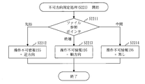
- S221 is an unusable direction determination process.
- the unusable direction determination unit 112 determines an unusable direction in which the target motion cannot be reproduced.
- step S2211 the impossible direction determination unit 112 determines the reference position indicated by the file reference pointer. If the file reference pointer indicates the beginning of the trace file 191, the process proceeds to S2212. If the file reference pointer indicates the end of the trace file 191, the process proceeds to S2213. If the file reference pointer indicates the middle of the trace file 191, the process proceeds to S2214.
- the impossibility direction determination unit 112 sets a value indicating the reverse direction in the operation impossibility information 195.
- the impossibility direction determination unit 112 sets a value indicating the forward direction in the operation impossibility information 195.
- the impossibility direction determination unit 112 sets a value indicating that there is no operation impossibility direction in the operation impossibility information 195. After S2212 to S2214, the impossible direction determination process (S221) ends.
- S222 is a button invalidation process.
- the reproduction screen display unit 121 invalidates a button for instructing reproduction in the unusable direction.
- the unusable direction process (S220) ends.
- the button invalidation process (S222) will be described with reference to FIG.
- the reproduction control unit 119 determines the operation impossible direction indicated by the operation impossible information 195. If the operation impossibility information 195 indicates the reverse direction, the process proceeds to S2222. If the operation impossibility information 195 indicates the forward direction, the process proceeds to S2223. When the operation impossibility information 195 indicates that there is no operation impossibility direction, the process proceeds to S2224.
- step S ⁇ b> 2222 the reproduction control unit 119 instructs the reproduction screen display unit 121 to invalidate the backward reproduction button 222 and the backward frame advance button 224. Then, the reproduction screen display unit 121 invalidates the reverse direction reproduction button 222 and the reverse direction frame advance button 224. Further, when the forward reproduction button 221 and the forward frame advance button 223 are disabled, the reproduction screen display unit 121 enables the forward reproduction button 221 and the forward frame advance button 223.
- step S ⁇ b> 2223 the reproduction control unit 119 instructs the reproduction screen display unit 121 to invalidate the forward reproduction button 221 and the forward frame advance button 223. Then, the reproduction screen display unit 121 disables the forward reproduction button 221 and the forward frame advance button 223. If the reverse direction reproduction button 222 and the reverse direction frame advance button 224 are disabled, the reproduction screen display unit 121 enables the reverse direction reproduction button 222 and the reverse direction frame advance button 224.
- step S2224 the reproduction control unit 119 instructs the reproduction screen display unit 121 to validate the reproduction instruction button. Then, the reproduction screen display unit 121 validates a disabled button among the forward direction reproduction button 221, the backward direction reproduction button 222, the forward direction frame advance button 223, and the backward direction frame advance button 224. After S2222 to S2224, the button invalidation processing (S222) ends.
- S230 is a reproduction instruction receiving process.
- the reception unit 101 receives a reproduction instruction.
- the reproduction instruction that is accepted is a forward direction reproduction instruction, a reverse direction reproduction instruction, a forward frame advance instruction, a backward frame advance instruction, an upper limit cycle setting instruction, or a lower limit period setting process.
- the process proceeds to S240. If the accepted reproduction instruction is a backward reproduction instruction, the process proceeds to S250. If the received reproduction instruction is a forward frame advance instruction, the process proceeds to S260. If the accepted reproduction instruction is a reverse frame advance instruction, the process proceeds to S270. When the accepted reproduction instruction is the upper limit cycle setting process, the process proceeds to S281. If the accepted reproduction instruction is the lower limit cycle setting process, the process proceeds to S282.
- S240 is a forward reproduction process.
- the reproduction unit 110 reproduces the target motion in the forward direction. Details of the forward reproduction process (S240) will be described later. After S240, the process returns to S220.
- S250 is a reverse direction reproduction process.
- the reproduction unit 110 reproduces the target motion in the reverse direction. Details of the reverse direction reproduction process (S250) will be described later. After S250, the process returns to S220.
- S260 is a forward frame advance process.
- the reproduction unit 110 changes the target state once in order of time. Details of the forward frame advance processing (S260) will be described later. After S260, the process returns to S220.
- S270 is a reverse frame advance process.
- the reproduction unit 110 changes the target state once in the reverse order of the time. Details of the reverse frame advance processing (S270) will be described later. After S270, the process returns to S220.
- S281 is an upper limit cycle setting process.
- the cycle setting unit 117 updates the upper limit cycle 192 stored in the storage unit 190 to the upper limit cycle specified by the upper limit cycle setting instruction. After S281, the process returns to S220.
- S282 is a lower limit cycle setting process.
- the cycle setting unit 117 updates the lower limit cycle 193 stored in the storage unit 190 to the lower limit cycle designated by the lower limit cycle setting instruction. After S282, the process returns to S220.
- the forward reproduction process (S240) will be described.
- the reproduction control unit 119 instructs the reproduction clock unit 102 to start incrementing the reproduction time 109.
- the reproduction clock unit 102 starts incrementing the reproduction time 109. That is, the reproduction clock unit 102 advances the reproduction time 109 in order of time.
- the reproduction control unit 119 clears the initial state flag 194. That is, the reproduction control unit 119 updates the flag value of the initial state flag 194 to a non-initial state value.
- S242 is a trace data reading process.
- the trace data reading unit 113 reads the trace data 191D indicated by the file reference pointer from the trace file 191. Then, the trace data reading unit 113 updates the file reference pointer to a value indicating the next trace data 191D in time order. Thereby, the trace data 191D can be read one by one in the time order. However, when there is no next trace data 191D in time order, that is, when the file reference pointer indicates the last trace data 191D, the trace data reading unit 113 updates the file reference pointer to a value indicating the end of the trace file 191. To do.
- S243 is a display interval and waiting time calculation process.
- the display interval calculation unit 114 calculates the display interval from the old display time to the new display time
- the wait time calculation unit 115 calculates the wait time until the new display time. Details of the display interval and waiting time calculation process (S243) will be described later.
- the time waiting unit 116 starts a waiting time timer in which the calculated waiting time is set, and waits until the waiting time timer times out.
- the waiting time timer is a timer that times out when the waiting time elapses. However, if the calculated waiting time is less than or equal to zero, S244 is not executed, and the process proceeds to S245-1.
- the reproduction control unit 119 calculates a new clock number using the new display time. In addition, the reproduction control unit 119 acquires a target identifier and a new state value from the read trace data 191D. Then, the reproduction control unit 119 inputs the new display time, the new clock number, the target identifier, and the new state value to the reproduction screen display unit 121.
- the reproduction screen display unit 121 changes the state of the target identified by the input target identifier to the state indicated by the input new state value in the graphic display 210 of the reproduction screen 200.
- the reproduction screen display unit 121 updates the reproduction time displayed on the graphic display 210 to the input new display time, and updates the clock number displayed on the graphic display 210 to the input new clock number. .
- the reproduction control unit 119 inputs the new display time to the reproduction clock unit 102. Then, the reproduction clock unit 102 updates the reproduction time 109 to the new display time, and advances the updated reproduction time 109 in order of time.
- the trace data reading unit 113 determines whether the file reference pointer indicates the end of the trace file 191. If the file reference pointer indicates the end of the trace file 191, the process proceeds to S247. If the file reference pointer does not indicate the end of the trace file 191, the process proceeds to S246-2.
- step S246-2 the reproduction control unit 119 inquires of the reception unit 101 whether a primary stop instruction has been received after the forward reproduction processing (S240) is started.
- the primary stop instruction is accepted after the forward reproduction process (S240) is started, the process proceeds to S247. If the primary stop instruction is not accepted after the forward reproduction process (S240) is started, the process returns to S242.
- the reproduction control unit 119 instructs the reproduction clock unit 102 to stop incrementing the reproduction time 109. Then, the reproduction clock unit 102 stops incrementing the reproduction time 109. That is, the reproduction clock unit 102 stops operating. After S247, the forward reproduction process (S240) ends.
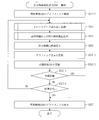
- the display interval and waiting time calculation process (S243) will be described with reference to FIG.
- the display interval calculation unit 114 acquires the occurrence time from the trace data 191D read this time, and sets the acquired occurrence time as the new display time.
- S2432 is a display interval calculation process.
- the display interval calculation unit 114 calculates a display interval that is an interval from the old display time to the new display time.
- the old display time is the new display time calculated last time. However, when there is no new display time calculated last time, that is, when the new display time is calculated for the first time, the old display time is the initial value of the reproduction time 109.
- the waiting time calculation unit 115 compares the calculated display interval with the upper limit cycle 192. When the calculated display interval is longer than the upper limit cycle 192, the process proceeds to S2434. If the calculated display interval is equal to or less than the upper limit cycle 192, the process proceeds to S2435.
- the waiting time calculation unit 115 acquires the current reproduction time 109 from the reproduction clock unit 102. Then, the waiting time calculation unit 115 calculates an interval between the current reproduction time 109 and the time when the upper limit cycle 192 elapses from the old display time as a waiting time.
- the waiting time calculation unit 115 compares the calculated display interval with the lower limit cycle 193. When the calculated display interval is shorter than the lower limit cycle 193, the process proceeds to S2436. If the calculated display interval is equal to or longer than the lower limit cycle 193, the process proceeds to S2437.
- the waiting time calculation unit 115 acquires the current reproduction time 109 from the reproduction clock unit 102. Then, the waiting time calculation unit 115 calculates the interval between the current reproduction time 109 and the time when the lower limit cycle 193 elapses from the old display time as the waiting time.
- the waiting time calculation unit 115 acquires the current reproduction time 109 from the reproduction clock unit 102. Then, the waiting time calculation unit 115 calculates an interval from the current reproduction time 109 to the new display time as a waiting time.
- the reverse direction reproduction process (S250) will be described with reference to FIG.
- the reproduction control unit 119 instructs the reproduction clock unit 102 to start decrementing the reproduction time 109. Then, the reproduction clock unit 102 starts decrementing the reproduction time 109. That is, the reproduction clock unit 102 advances the reproduction time 109 in the reverse order.
- S252 is a trace data reading process.
- the trace data reading unit 113 reads one trace data 191D from the trace file 191 in reverse order of time. Details of the trace data reading process (S252) will be described later.
- S253 is a display interval and waiting time calculation process.
- the display interval calculation unit 114 calculates the display interval from the new display time to the old display time
- the wait time calculation unit 115 calculates the wait time until the new display time. Details of the display interval and waiting time calculation process (S253) will be described later.
- the time waiting unit 116 starts a waiting time timer in which the calculated waiting time is set, and waits until the waiting time timer times out.
- the waiting time timer is a timer that times out when the waiting time elapses. However, if the calculated waiting time is less than or equal to zero, S254 is not executed, and the process proceeds to S255-1.
- the reproduction control unit 119 calculates a new clock number using the new display time. Further, the reproduction control unit 119 acquires the target identifier and the old state value from the read trace data 191D. Then, the reproduction control unit 119 inputs the new display time, the new clock number, the target identifier, and the old state value to the reproduction screen display unit 121.
- the reproduction screen display unit 121 changes the state of the target identified by the input target identifier in the graphic display 210 of the reproduction screen 200 to the state indicated by the input old state value.
- the reproduction screen display unit 121 updates the reproduction time displayed on the graphic display 210 to the input new display time, and updates the clock number displayed on the graphic display 210 to the input new clock number. .
- the reproduction control unit 119 inputs the new display time to the reproduction clock unit 102. Then, the reproduction clock unit 102 updates the reproduction time 109 to the new display time and advances the updated reproduction time 109 in the reverse order.
- the trace data reading unit 113 determines whether the flag value of the initial state flag 194 is an initial state value. If the flag value of the initial state flag 194 is the initial state value, the process proceeds to S257. If the flag value of the initial state flag 194 is a non-initial state value, the process proceeds to S256-2.
- step S256-2 the reproduction control unit 119 inquires of the reception unit 101 whether a primary stop instruction has been received after the reverse direction reproduction process (S250) is started.
- the process proceeds to S257. If the primary stop instruction has not been accepted after the reverse reproduction process (S250) has been started, the process returns to S252.
- the reproduction control unit 119 instructs the reproduction clock unit 102 to stop decrementing the reproduction time 109. Then, the reproduction clock unit 102 stops decrementing the reproduction time 109. That is, the reproduction clock unit 102 stops operating.
- the reverse reproduction process (S250) ends.
- step S2521 the reproduction control unit 119 determines whether the file reference pointer indicates the top trace data 191D of the trace file 191, that is, the top trace data 191D in time order. If the file reference pointer indicates the beginning of the trace file 191, the process proceeds to S2522. If the file reference pointer indicates other than the beginning of the trace file 191, the process proceeds to S2524.
- step S2522 the reproduction control unit 119 instructs the reproduction clock unit 102 to initialize the reproduction time 109. Then, the reproduction control unit 119 initializes the reproduction time 109. That is, the reproduction control unit 119 updates the reproduction time 109 to the initial value.
- the reproduction control unit 119 initializes the initial state flag 194. That is, the reproduction control unit 119 updates the flag value of the initial state flag 194 to the initial state value.
- the trace data reading process (S252) ends.
- the reproduction control unit 119 updates the file reference pointer to a value indicating the next trace data 191D in the reverse order of time.
- step S2525 the trace data reading unit 113 reads the trace data 191D indicated by the file reference pointer from the trace file 191. After S2525, the trace data reading process (S252) ends.
- the display interval and waiting time calculation process (S253) will be described.
- the display interval calculation unit 114 acquires the occurrence time from the trace data 191D read this time, and calculates a time that goes back the correction time from the acquired occurrence time as a new display time.
- This new display time means the time immediately before the target state changes.
- S2532 is a display interval calculation process.
- the display interval calculation unit 114 calculates a display interval that is an interval from the new display time to the old display time.
- the old display time is the new display time calculated last time.
- the waiting time calculation unit 115 compares the calculated display interval with the upper limit cycle 192. If the calculated display interval is longer than the upper limit cycle 192, the process proceeds to S2534. If the calculated display interval is equal to or less than the upper limit cycle 192, the process proceeds to S2535.
- step S ⁇ b> 2534 the waiting time calculation unit 115 acquires the current reproduction time 109 from the reproduction clock unit 102. Then, the waiting time calculation unit 115 calculates the interval between the current reproduction time 109 and the time that goes back the upper limit cycle 192 from the old display time as the waiting time.
- the waiting time calculation unit 115 compares the calculated display interval with the lower limit cycle 193. If the calculated display interval is shorter than the lower limit cycle 193, the process proceeds to S2536. If the calculated display interval is equal to or longer than the lower limit cycle 193, the process proceeds to S2537.
- the waiting time calculation unit 115 acquires the current reproduction time 109 from the reproduction clock unit 102. Then, the waiting time calculation unit 115 calculates the interval between the current reproduction time 109 and the time that goes back the lower limit cycle 193 from the old display time as the waiting time.
- step S ⁇ b> 2537 the waiting time calculation unit 115 acquires the current reproduction time 109 from the reproduction clock unit 102. Then, the waiting time calculation unit 115 calculates an interval from the current reproduction time 109 to the new display time as a waiting time.
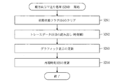
- the forward frame advance process (S260) will be described with reference to FIG.
- the reproduction control unit 119 clears the initial state flag 194. That is, the reproduction control unit 119 updates the flag value of the initial state flag 194 to a non-initial state value.
- the trace data reading unit 113 reads the trace data 191D indicated by the file reference pointer from the trace file 191. Then, the trace data reading unit 113 updates the file reference pointer to a value indicating the next trace data 191D in time order. However, when there is no next trace data 191D in time order, that is, when the file reference pointer indicates the last trace data 191D, the trace data reading unit 113 updates the file reference pointer to a value indicating the end of the trace file 191. To do.
- the reproduction control unit 119 acquires the generation time, the number of cycles, the target identifier, and the new state value from the read trace data 191D, and the acquired generation time, the number of cycles, the target identifier, and the new state value. Input to the reproduction screen display unit 121.
- the reproduction screen display unit 121 changes the state of the target identified by the input target identifier to the state indicated by the input new state value in the graphic display 210 of the reproduction screen 200.
- the reproduction screen display unit 121 updates the reproduction time displayed on the graphic display 210 to the input occurrence time, and updates the number of clocks displayed on the graphic display 210 to the input cycle number.
- the reproduction control unit 119 inputs the acquired occurrence time to the reproduction clock unit 102. Then, the reproduction clock unit 102 updates the reproduction time 109 to the generation time. After S264, the forward frame advance processing (S260) ends.
- step S271 the reproduction control unit 119 determines whether the file reference pointer indicates the top trace data 191D of the trace file 191, that is, the top trace data 191D in time order. If the file reference pointer indicates the beginning of the trace file 191, the process proceeds to S272. If the file reference pointer indicates a position other than the head of the trace file 191, the process proceeds to S274.
- the reproduction control unit 119 initializes the initial state flag 194. That is, the reproduction control unit 119 updates the flag value of the initial state flag 194 to the initial state value.
- step S273 the reproduction control unit 119 instructs the reproduction clock unit 102 to initialize the reproduction time 109. Then, the reproduction clock unit 102 initializes the reproduction time 109. That is, the reproduction clock unit 102 updates the reproduction time 109 to the initial value.
- the reverse frame advance processing (S270) ends.
- the reproduction control unit 119 updates the file reference pointer to a value indicating the next trace data 191D in the reverse order of time.
- the trace data reading unit 113 reads the trace data 191D indicated by the file reference pointer from the trace file 191.
- the reproduction control unit 119 acquires the occurrence time, the state identifier, and the old state value from the read trace data 191D.
- the reproduction control unit 119 calculates a time that goes back the correction time from the acquired occurrence time as a new display time.
- This new display time means the time immediately before the target state changes.
- the reproduction control unit 119 calculates a new clock number using the calculated new display time.
- the reproduction control unit 119 inputs the new display time, the new clock number, the state identifier, and the old state value to the reproduction screen display unit 121.
- the reproduction screen display unit 121 changes the state of the target identified by the input target identifier to the state indicated by the input old state value in the graphic display 210 of the reproduction screen 200.
- the reproduction screen display unit 121 updates the reproduction time displayed on the graphic display 210 to the input new display time, and updates the clock number displayed on the graphic display 210 to the input new clock number. .
- the reproduction control unit 119 inputs the new display time to the reproduction clock unit 102. Then, the reproduction clock unit 102 updates the reproduction time 109 to the new display time. After S277, the reverse frame advance processing (S270) ends.
- the simulation reproducing apparatus 100 pauses the change of the target state according to the pause instruction, and changes the target state once in the reverse order of the time according to the reverse frame advance instruction. Therefore, the user can check the change in the target state retroactively. And when a malfunction occurs, the cause can be easily identified.
- the simulation reproducing apparatus 100 changes the target state once each in accordance with the forward frame advance instruction and the backward frame advance instruction. Therefore, the user can confirm the change of the target state one by one.
- the simulation reproduction apparatus 100 continuously changes the target state in the reverse order of time according to the backward reproduction instruction. Therefore, the user can continuously check the change in the target state in the reverse order of the time by one backward reproduction instruction without performing the backward frame advance instruction a plurality of times.
- the simulation reproducing apparatus 100 sets the upper limit cycle 192 in accordance with the upper limit cycle setting instruction, and makes the time during which the object continues to be displayed without changing the state shorter than the upper limit cycle 192. Therefore, when the target state does not change for a long time, the user can shorten the time required for the confirmation work by shortening the upper limit cycle 192 by an upper limit cycle setting instruction.
- the simulation reproducing apparatus 100 sets the lower limit cycle 193 according to the lower limit cycle setting instruction, and makes the time during which the object continues to be displayed without changing the state longer than the lower limit cycle 193. Therefore, when the target state changes at a high speed, the user can prevent an oversight of confirmation by lengthening the lower limit cycle 193 by a lower limit cycle setting instruction.
- the simulation reproduction apparatus 100 applies both the upper limit cycle 192 and the lower limit cycle 193 in a compatible manner. Therefore, the user can obtain the effects of both shortening and extending the time for which the object continues to be displayed without changing the state.
- the simulation reproducing apparatus 100 displays a time which is a minute time from the generation time and goes back to the graphic display 210 during backward reproduction or backward frame advance.
- a time which is a minute time from the generation time and goes back to the graphic display 210 during backward reproduction or backward frame advance.
- Embodiment 2 A form in which the delay time generated when the graphic display representing the state of the object in the simulation changes is considered when reproducing the operation of the object will be described with reference to FIGS. However, the description which overlaps with Embodiment 1 is abbreviate
- the functional configuration of the simulation reproduction apparatus 100 is the same as that of the first embodiment except for the following points.
- the trace data 191D of the trace file 191 includes a delay time as shown in FIG.
- the delay time is a time generated when the graphic display representing the target state is changed in the simulation.
- the waiting time calculation unit 115 corrects the waiting time by subtracting the delay time included in the new trace data from the calculated waiting time.
- the reproduction screen display unit 121 changes the target state when the corrected waiting time has elapsed.
- the reproduction clock unit 102 updates the reproduction time 109 to the new display time when the corrected waiting time has elapsed.
- S125 of the simulation process (S120) described in FIG. 8 is different from that of the first embodiment as follows.
- the simulation unit 180 when the simulation unit 180 instructs the simulation screen display unit 122 to update the graphic display, the simulation unit 180 starts measuring the update completion time.
- the simulation screen display unit 122 outputs an update completion notification when the graphic display update is completed.
- the output update completion notification is input to the simulation unit 180.
- the simulation unit 180 finishes measuring the update completion time when the update completion notification is input.
- the update completion time is the time required for updating the graphic display, and can be expressed by the following equation.
- the update instruction time is the time when the simulation unit 180 instructs the simulation screen display unit 122 to update the graphic display.
- the update completion time is the time when the update completion notification is input to the simulation unit 180.
- Update completion time Update completion time-Update instruction time
- the simulation unit 180 calculates a time obtained by subtracting the specified time from the update completion time as a delay time, and sets the calculated delay time in the recorded trace data 191D.
- the specified time is a predetermined time.
- An example of the prescribed time is the update completion notification transmission time or the update completion notification transmission time plus the target response time.
- the update completion notification transmission time is the time from when the update completion notification is output from the simulation screen display unit 122 to when the output update completion notification is input to the simulation unit 180.
- the response time of the target is about 50 to 100 nanoseconds.
- the display interval and waiting time calculation process (S243) will be described with reference to FIG.
- the display interval and waiting time calculation process (S243) includes S2438 in addition to S2431 to S2437 described in the first embodiment.
- the waiting time calculation unit 115 acquires a delay time from the read trace data 191D. Then, the waiting time calculation unit 115 corrects the waiting time by subtracting the acquired delay time from the calculated waiting time.
- the time waiting unit 116 waits until the corrected waiting time elapses in S244 of the forward reproduction process (S240) described with reference to FIG.
- the display interval and waiting time calculation process (S253) includes S2538 in addition to S2531 to S2537 described in the first embodiment.
- the waiting time calculation unit 115 acquires a delay time from the read trace data 191D. Then, the waiting time calculation unit 115 corrects the waiting time by subtracting the acquired delay time from the calculated waiting time.
- the time waiting unit 116 waits until the corrected waiting time elapses in S254 of the reverse direction reproduction process (S250) described in FIG.
- the simulation reproduction apparatus 100 corrects the waiting time by subtracting the delay time from the waiting time. Thereby, the change in the state of the target can be reproduced with a graphic display closer to the target of the actual machine.
- Each embodiment is an example of a preferred embodiment and is not intended to limit the technical scope of the present invention. Each embodiment may be implemented partially or in combination with other embodiments.
- the processing procedure described using the flowchart and the like is an example of the processing procedure of the simulation reproduction method and the simulation reproduction program.
- the trace file 191 may be either a normal file stored on the hard disk or a memory mapped file read into the memory. By replacing the file reference pointer with a memory address, the trace file 191 can be handled in a normal memory space.
- the simulation unit 180 may set either the generation time or the number of cycles in the trace data 191D during simulation. Further, the simulation reproduction apparatus 100 may include a mechanism for converting the generation time (or the number of cycles) set in the trace data 191D into the number of cycles (or the generation time). The mechanism may perform conversion by multiplying by the speed ratio as in Patent Document 1. The conversion may be performed when the trace data 191D is read.
- the time waiting unit 116 may detect the elapse of the waiting time using a one-shot timer, or may detect the elapse of the waiting time by polling the reproduction time 109. Similar to a general microcomputer simulator, the simulation unit 180 may perform the simulation by any one of the first method and the second method.
- the first method is a method in which the instruction of the simulation program is converted into an instruction for a virtual microcomputer, and the converted instruction is executed by the virtual microcomputer.
- the second method is a method in which a simulation program instruction is converted into a host processor instruction, and the converted instruction is executed by the host processor.
- the simulation reproduction apparatus 100 is realized by executing a simulation program and a simulation reproduction program by a server, workstation, personal computer, or other computer on which an operating system is operating.
- the simulation reproduction device 100 includes a processor 801, an input device 802, a display 803, a storage device 804, a memory 805, and a timer 806.
- the simulation program and the simulation reproduction program are stored in the memory 805 and executed by the processor 801.
- Data used, generated or input / output by the simulation reproduction apparatus 100 is stored in the memory 805 or the storage device 804.
- An example of the storage device 804 is a hard disk or a nonvolatile memory.
- the user instruction is input to the simulation reproducing apparatus 100 using an input device 802 such as a keyboard, a mouse, a pointing device, or a touch panel.
- the operation screen, simulation screen, and reproduction screen 200 of the simulation reproduction apparatus 100 are displayed on the display 803.
- the accepting unit 101 is realized by a processor 801, an input device 802, and a display 803.
- the reproduction clock unit 102 is realized by a processor 801, a memory 805, and a timer 806.
- the reproduction unit 110 and the simulation unit 180 are realized by a processor 801, a memory 805, and a timer 806.
- the display unit 120 is realized by a processor 801, a memory 805, and a display 803.
- the storage unit 190 is realized by the memory 805 and the storage device 804.
- 100 simulation reproduction device 101 reception unit, 102 reproduction clock unit, 109 reproduction time, 110 reproduction unit, 111 initialization unit, 112 impossible direction determination unit, 113 trace data reading unit, 114 display interval calculation unit, 115 waiting time calculation unit 116, time waiting unit, 117 period setting unit, 119 reproduction control unit, 120 display unit, 121 reproduction screen display unit, 122 simulation screen display unit, 130 timing control unit, 180 simulation unit, 189 simulation screen file, 190 storage unit, 191 trace file, 191D trace data, 192 upper limit cycle, 193 lower limit cycle, 194 initial status flag, 195 operation impossible information, 199 reproduction screen file, 200 reproduction screen, 210 graph Display, 220 button widget, 221 forward reproduction button, 222 backward reproduction button, 223 forward frame advance button, 224 backward frame advance button, 225 upper limit cycle button, 226 lower limit cycle button, 230 message area, 801 processor , 802 input device, 803 display, 804 storage device, 805 memory, 806 timer.
Landscapes
- Engineering & Computer Science (AREA)
- Theoretical Computer Science (AREA)
- General Engineering & Computer Science (AREA)
- Physics & Mathematics (AREA)
- General Physics & Mathematics (AREA)
- Computer Hardware Design (AREA)
- Quality & Reliability (AREA)
- Software Systems (AREA)
- Evolutionary Computation (AREA)
- Geometry (AREA)
- Debugging And Monitoring (AREA)
Abstract
記憶部(190)は対象の動作をシミュレーションして得られたトレースファイル(191)を記憶する。受付部(101)は順方向再現指示を受け付ける。再現部(110)はトレースファイルからトレースデータを1つずつ読み出す。再現部は、今回読み出された新トレースデータに含まれる発生時刻に対応する新表示時刻と前回読み出された旧トレースデータに含まれる発生時刻に対応する旧表示時刻とに基づいて、グラフィック表示を更新するタイミングを求める。表示部(120)は、求められたタイミングで、グラフィック表示された対象の状態を新トレースデータに含まれる新状態値が示す状態に変化させる。
Description
本発明は、シミュレーションされた対象の動作をグラフィック表示で再現する技術に関するものである。
近年の組み込み機器向けのソフトウェア開発では、ソフトウェアデバッグを早期に開始するため、ソフトウェアが動作するマイクロコンピュータ及びその周辺機器の動作を模擬するソフトウェアシミュレータが用いられる。このシミュレータを用いることにより、実際にソフトウェアが動作するハードウェア試験環境が完成する前からソフトウェアデバッグを行うことができる。
ソフトウェアシミュレータは、周辺機器の状態またはマイクロコンピュータの入出力端子の状態をグラフィックで表示することが可能である。例えば、ソフトウェアシミュレータは、周辺機器の状態として、LEDの点灯および消灯をグラフィックで表示する。また、ソフトウェアシミュレータは、入出力端子の状態として、入出力端子に入出力される信号の信号値をグラフィックで表示する。
そのため、ユーザは、ソフトウェアシミュレータによるシミュレーションの実行中に、周辺機器の状態またはマイクロコンピュータの入出力端子の状態が変化する様子をグラフィックで視認することができる。
そのため、ユーザは、ソフトウェアシミュレータによるシミュレーションの実行中に、周辺機器の状態またはマイクロコンピュータの入出力端子の状態が変化する様子をグラフィックで視認することができる。
特許文献1は上記のようなシミュレータを開示している。特許文献1に開示されたシミュレータは以下のように動作する。
シミュレータは、シミュレーションの実行中に状態の変化が発生した発生時刻と変化後の状態値である更新値とをトレースデータとして記録する。
シミュレーションの終了後、シミュレータは、トレースデータの発生時刻を、状態の変化を再現して表示する再現表示時刻に変換する。
そして、シミュレータは、トレースデータを読み出して、再現表示時刻に状態の変化をグラフィックで表示する。
これにより、シミュレータは、シミュレーションを再度実行しなくても、トレースデータを用いて状態の変化を再現することができる。
また、シミュレータは、シミュレーション時の時間の経過速度に対する再現時の時間の経過速度の速度比を用いて発生時刻を再現表示時刻に変換することによって、状態の変化を再現する速さを変更することができる。例えば、シミュレータは状態の変化を高速に再現することができる。
しかし、従来のシミュレータは、時間の経過の逆順に、状態の変化を再現することができない。そのため、従来のシミュレータは以下のような点で不便である。
シミュレーションにおいて不正な動作が発生した場合、ユーザは、不正な動作の原因を見つけるために、不正な動作に気付いた時点から過去へ遡りながら状態の変化を確認したい。
しかし、従来のシミュレータは時間の経過の逆順に状態の変化を再現することができないため、ユーザは、シミュレーションを開始した時点から時間の経過順に状態の変化を確認しながら、不正な動作の原因を見つけなければならない。その結果、不正な動作の原因を見つけるまでに時間がかかってしまう。
シミュレーションにおいて不正な動作が発生した場合、ユーザは、不正な動作の原因を見つけるために、不正な動作に気付いた時点から過去へ遡りながら状態の変化を確認したい。
しかし、従来のシミュレータは時間の経過の逆順に状態の変化を再現することができないため、ユーザは、シミュレーションを開始した時点から時間の経過順に状態の変化を確認しながら、不正な動作の原因を見つけなければならない。その結果、不正な動作の原因を見つけるまでに時間がかかってしまう。
また、従来のシミュレータは、状態の変化を再現している途中で、状態の変化を再現する速さを変えることができない。
そのため、ユーザは、再現の速さが早ければ状態の変化を見落としてしまい、再現の速さが遅ければ状態の変化の確認に時間がかかってしまう。
例えば、再現中のLEDが高速に点滅している場合、ユーザは、視認する時間を確保するために、LEDが点滅する時間間隔を長くしたい。しかし、従来のシミュレータは、再現中に再現の速さを変えることができないため、LEDが点滅する時間間隔を長くすることができない。また、再現中のLEDの点灯状態が変わらない場合、ユーザは、確認作業の効率化のために、点灯状態が変わらないLEDが表示され続ける時間を短くしたい。しかし、従来のシミュレータは、再現中に再現の速さを変えることができないため、点灯状態が変わらないLEDが表示され続ける時間を短くすることができない。
本発明は、シミュレーションされた対象の動作をグラフィック表示で再現した際に、対象が状態を変化しないまま表示され続ける時間を上限周期以内にすることができるようにすることを目的とする。
本発明のシミュレーション再現装置は、シミュレーションされた対象の動作をグラフィック表示で再現する。
前記シミュレーション再現装置は、
前記対象の動作をシミュレーションして得られたファイルであり、前記対象の状態の変化が発生した発生時刻と、状態が変化した後の状態を示す新状態値と、を含んだ1つ以上のトレースデータが記録されたファイルであるトレースファイルを記憶する記憶部と、
前記対象が状態を変化しないまま表示され続ける時間の長さの上限である上限周期を受け付ける受付部と、
前記トレースファイルから前記トレースデータを1つずつ読み出すトレースデータ読み出し部と、
今回読み出されたトレースデータである新トレースデータに含まれる発生時刻に対応する新表示時刻と前回読み出されたトレースデータである旧トレースデータに含まれる発生時刻に対応する旧表示時刻との間隔が前記上限周期より長い場合、前記旧表示時刻から前記上限周期ずれた時刻に、グラフィック表示された対象の状態を前記新トレースデータに含まれる新状態値が示す状態に変化させる表示部とを備える。
本発明によれば、シミュレーションされた対象の動作をグラフィック表示で再現した際に、対象が状態を変化しないまま表示され続ける時間を上限周期以内にすることができる。
実施の形態1.
シミュレーションされた対象の動作をグラフィック表示で再現するシミュレーション再現装置100について、図1から図20に基づいて説明する。
シミュレーションされた対象の動作をグラフィック表示で再現するシミュレーション再現装置100について、図1から図20に基づいて説明する。
***構成の説明***
図1に基づいて、シミュレーション再現装置100について説明する。
シミュレーション再現装置100は、受付部101と、再現部110と、再現時計部102と、表示部120と、シミュレーション部180と、記憶部190とを備える。
図1に基づいて、シミュレーション再現装置100について説明する。
シミュレーション再現装置100は、受付部101と、再現部110と、再現時計部102と、表示部120と、シミュレーション部180と、記憶部190とを備える。
受付部101は、シミュレーション再現装置100を使用するユーザによってシミュレーション再現装置100に入力されるユーザ指示を受け付ける。
ユーザ指示には、シミュレーション指示と、再現指示とがある。
シミュレーション指示は、対象の動作をシミュレーションさせる指示である。
再現指示は、シミュレーションされた対象の動作をグラフィック表示で再現させる指示である。
ユーザ指示には、シミュレーション指示と、再現指示とがある。
シミュレーション指示は、対象の動作をシミュレーションさせる指示である。
再現指示は、シミュレーションされた対象の動作をグラフィック表示で再現させる指示である。
再現指示には、再現開始指示と、順方向再現指示と、逆方向再現指示と、一時停止指示と、順方向コマ送り指示と、逆方向コマ送り指示と、パラメータ設定指示がある。
再現開始指示は、対象の動作の再現を開始させる指示である。
順方向再現指示は、対象の動作を時刻順に再現する順方向再現を行わせる指示である。
逆方向再現指示は、対象の動作を時刻の逆順に再現する逆方向再現を行わせる指示である。
一時停止指示は、対象の動作の再現を一時停止させる指示である。
順方向コマ送り指示は、対象の状態が時刻順に1回変化する順方向コマ送りを行わせる指示である。
逆方向コマ送り指示は、対象の状態が時刻の逆順に1回変化する逆方向コマ送りを行わせる指示である。
パラメータ設定指示は、対象の動作を再現するときに用いるパラメータを設定させる指示である。
再現開始指示は、対象の動作の再現を開始させる指示である。
順方向再現指示は、対象の動作を時刻順に再現する順方向再現を行わせる指示である。
逆方向再現指示は、対象の動作を時刻の逆順に再現する逆方向再現を行わせる指示である。
一時停止指示は、対象の動作の再現を一時停止させる指示である。
順方向コマ送り指示は、対象の状態が時刻順に1回変化する順方向コマ送りを行わせる指示である。
逆方向コマ送り指示は、対象の状態が時刻の逆順に1回変化する逆方向コマ送りを行わせる指示である。
パラメータ設定指示は、対象の動作を再現するときに用いるパラメータを設定させる指示である。
パラメータ設定指示には、上限周期設定指示と、下限周期設定指示とがある。
上限周期設定指示は上限周期192を設定させる指示であり、下限周期設定指示は下限周期193を設定させる指示である。
上限周期192は、対象が状態を変化しないまま表示され続ける時間の長さの上限である。上限周期192の初期値は最長周期を表す値である。
下限周期193は、対象が状態を変化しないまま表示され続ける時間の長さの下限である。下限周期193の初期値は最短周期を表す値である。
上限周期設定指示は上限周期192を設定させる指示であり、下限周期設定指示は下限周期193を設定させる指示である。
上限周期192は、対象が状態を変化しないまま表示され続ける時間の長さの上限である。上限周期192の初期値は最長周期を表す値である。
下限周期193は、対象が状態を変化しないまま表示され続ける時間の長さの下限である。下限周期193の初期値は最短周期を表す値である。
シミュレーション部180は、シミュレーション指示が受け付けられた場合、シミュレーションプログラムを実行することによって対象の動作をシミュレーションして、トレースファイル191を生成する。
対象の動作がシミュレーションされている間、シミュレーションされた対象の動作は、シミュレーション画面にグラフィック表示される。シミュレーション画面は、表示部120のシミュレーション画面表示部122によって生成される。
対象の動作がシミュレーションされている間、シミュレーションされた対象の動作は、シミュレーション画面にグラフィック表示される。シミュレーション画面は、表示部120のシミュレーション画面表示部122によって生成される。
図2に基づいて、トレースファイル191の構成について説明する。
トレースファイル191は、1つ以上のトレースデータ191Dが記録されたファイルである。図中の1行が1つのトレースデータ191Dに相当する。
トレースデータ191Dは、発生時刻と、サイクル数と、対象識別子と、新状態値と、旧状態値とを含んでいる。
トレースファイル191は、1つ以上のトレースデータ191Dが記録されたファイルである。図中の1行が1つのトレースデータ191Dに相当する。
トレースデータ191Dは、発生時刻と、サイクル数と、対象識別子と、新状態値と、旧状態値とを含んでいる。
発生時刻は、対象の状態の変化が発生した時刻である。
サイクル数は、発生時刻を仮想クロックのカウント数で表した値である。仮想クロックは仮想コンピュータのクロックであり、仮想コンピュータは対象が動作する仮想のコンピュータである。
発生時刻とサイクル数とは以下の関係を有する。仮想クロック周期は仮想クロックの周期である。
サイクル数=発生時刻/仮想クロック周期
例えば、サイクル数が16進数で12Aナノ秒であり、仮想クロック周期が16進数でAナノ秒である場合、発生時刻は16進数でBA4ナノ秒(=12A×A)である。
サイクル数は、発生時刻を仮想クロックのカウント数で表した値である。仮想クロックは仮想コンピュータのクロックであり、仮想コンピュータは対象が動作する仮想のコンピュータである。
発生時刻とサイクル数とは以下の関係を有する。仮想クロック周期は仮想クロックの周期である。
サイクル数=発生時刻/仮想クロック周期
例えば、サイクル数が16進数で12Aナノ秒であり、仮想クロック周期が16進数でAナノ秒である場合、発生時刻は16進数でBA4ナノ秒(=12A×A)である。
対象識別子は、対象を識別する。対象の一例はLEDおよび周辺機器である。
新状態値は、対象の状態が変化した後の対象の状態を示す。
旧状態値は、対象の状態が変化する前の対象の状態を示す。
1つ以上のトレースデータ191Dは、発生時刻の時刻順にトレースファイル191に記録されている。
新状態値は、対象の状態が変化した後の対象の状態を示す。
旧状態値は、対象の状態が変化する前の対象の状態を示す。
1つ以上のトレースデータ191Dは、発生時刻の時刻順にトレースファイル191に記録されている。
図1に戻って説明を続ける。
再現部110は、再現指示が受け付けられた場合、トレースファイル191と再現時刻109と上限周期192と下限周期193と初期状態フラグ194と操作不可情報195とを用いて、対象の動作をグラフィック表示で再現する。
再現時刻109は、対象の動作がシミュレーションされた時間帯の時刻を再現した時刻であり、再現時計部102から取得される。
初期状態フラグ194は、再現されている対象の状態が初期状態であるか否かを示すフラグである。初期状態を示すフラグ値を初期状態値とし、初期状態以外の状態を示すフラグ値を非初期状態値とする。
操作不可情報195は、時刻順および時刻の逆順に対象の動作を再現できるかを示す情報である。
再現時計部102は、再現時刻109を示す時計として機能する。再現時刻109は再現部110、表示部120およびシミュレーション部180から随時取得される。
順方向再現指示が受け付けられた場合、再現時計部102は再現時刻109を時刻順に進める。
逆方向再現指示が受け付けられた場合、再現時計部102は再現時刻109を逆順に進める。
順方向再現指示が受け付けられた場合、再現時計部102は再現時刻109を時刻順に進める。
逆方向再現指示が受け付けられた場合、再現時計部102は再現時刻109を逆順に進める。
表示部120は、再現画面表示部121と、シミュレーション画面表示部122とを備える。
再現画面表示部121は、再現画面ファイル199と再現時刻109とを用いて再現画面200を表示する。
再現画面ファイル199は、再現画面200を構成する画像を備えるファイルである。
再現画面表示部121は、再現画面ファイル199と再現時刻109とを用いて再現画面200を表示する。
再現画面ファイル199は、再現画面200を構成する画像を備えるファイルである。
図3に基づいて、再現画面200について説明する。
再現画面200は、グラフィック表示210と、ボタンウィジェット220と、メッセージ領域230とを備える。
グラフィック表示210は、シミュレーションした対象の状態の変化を表すグラフィックである。
例えば、グラフィック表示210は、LED1とLED2とを対象として、LED1とLED2とのそれぞれの点灯状態を示す。また、グラフィック表示210は、再現時刻109と再現時刻109に対応するクロック数とを示す。図中のTime欄に再現時刻109を示し、図中のClk欄にクロック数を示している。Time欄の再現時刻109およびClk欄のクロック数は再現時計部102の再現時刻109と共に変化する。
例えば、LED1とLED2とが消灯している状態から、LED1だけが点灯した場合、図4に示すように、LED1の状態が消灯状態から点灯状態に変化する。
ボタンウィジェット220は、順方向再現ボタン221と、逆方向再現ボタン222と、順方向コマ送りボタン223と、逆方向コマ送りボタン224と、上限周期ボタン225と、下限周期ボタン226とを備える。
順方向再現ボタン221は順方向再現用のボタンである。順方向再現ボタン221が押下されると順方向再現指示が受け付けられる。
逆方向再現ボタン222は逆方向再現用のボタンである。逆方向再現ボタン222が押下されると逆方向再現指示が受け付けられる。
順方向コマ送りボタン223は順方向コマ送り用のボタンである。順方向コマ送りボタン223が押下されると順方向コマ送り指示が受け付けられる。
逆方向コマ送りボタン224は逆方向コマ送り用のボタンである。逆方向コマ送りボタン224が押下されると逆方向コマ送り指示が受け付けられる。
上限周期ボタン225は上限周期設定用のボタンである。上限周期ボタン225が押下されると上限周期192を指定するためのダイアログが表示され、表示されたダイアログで指定された上限周期192の設定指示が受け付けられる。
下限周期ボタン226は下限周期設定用のボタンである。下限周期ボタン226が押下されると下限周期193を指定するためのダイアログが表示され、表示されたダイアログで指定された下限周期193の設定指示が受け付けられる。
操作不可情報195が操作不可方向として逆方向を示す場合、逆方向再現ボタン222および逆方向コマ送りボタン224は無効化される。逆方向再現ボタン222および逆方向コマ送りボタン224が無効化された場合、逆方向再現指示および逆方向コマ送り指示は受け付けられず、逆方向再現および逆方向コマ送りは行われない。
操作不可情報195が操作不可方向として順方向を示す場合、順方向再現ボタン221および順方向コマ送りボタン223は無効化される。順方向再現ボタン221および順方向コマ送りボタン223が無効化された場合、順方向再現指示および順方向コマ送り指示は受け付けられず、順方向再現および順方向コマ送りは行われない。
例えば、順方向再現ボタン221が無効化された場合、図5に示すように、順方向再現ボタン221の表示は変化する。他のボタンについても同様である。
操作不可情報195が操作不可方向として順方向を示す場合、順方向再現ボタン221および順方向コマ送りボタン223は無効化される。順方向再現ボタン221および順方向コマ送りボタン223が無効化された場合、順方向再現指示および順方向コマ送り指示は受け付けられず、順方向再現および順方向コマ送りは行われない。
例えば、順方向再現ボタン221が無効化された場合、図5に示すように、順方向再現ボタン221の表示は変化する。他のボタンについても同様である。
メッセージ領域230はメッセージが表示される領域である。
例えば、無効化された順方向再現ボタン221が押下された場合、順方向再現指示が無効である旨のエラーメッセージがメッセージ領域230に表示される。
例えば、無効化された順方向再現ボタン221が押下された場合、順方向再現指示が無効である旨のエラーメッセージがメッセージ領域230に表示される。
図1に戻って説明を続ける。
シミュレーション画面表示部122は、シミュレーション画面ファイル189と再現時刻109とを用いてシミュレーション画面を表示する。
シミュレーション画面ファイル189は、シミュレーション画面を構成する画像を備えるファイルである。
シミュレーション画面は、再現画面200のグラフィック表示210に相当する表示を含んだ画面である。
シミュレーション画面表示部122は、シミュレーション画面ファイル189と再現時刻109とを用いてシミュレーション画面を表示する。
シミュレーション画面ファイル189は、シミュレーション画面を構成する画像を備えるファイルである。
シミュレーション画面は、再現画面200のグラフィック表示210に相当する表示を含んだ画面である。
記憶部190は、シミュレーション再現装置100が使用、生成または入出力するデータを記憶する。
記憶部190に記憶されるデータの一例は、トレースファイル191、上限周期192、下限周期193、初期状態フラグ194、操作不可情報195、再現画面ファイル199およびシミュレーション画面ファイル189である。
記憶部190に記憶されるデータの一例は、トレースファイル191、上限周期192、下限周期193、初期状態フラグ194、操作不可情報195、再現画面ファイル199およびシミュレーション画面ファイル189である。
図6に基づいて、再現部110の機能構成について説明する。
再現部110は、初期化部111と、不可方向判定部112と、トレースデータ読み出し部113と、表示間隔算出部114と、待ち時間算出部115と、時間待ち部116とを備える。さらに、再現部110は、周期設定部117と再現制御部119とを備える。
再現部110は、初期化部111と、不可方向判定部112と、トレースデータ読み出し部113と、表示間隔算出部114と、待ち時間算出部115と、時間待ち部116とを備える。さらに、再現部110は、周期設定部117と再現制御部119とを備える。
初期化部111は、対象の動作をグラフィック表示で再現するための初期化処理を行う。初期化処理の詳細については後述する。
不可方向判定部112は、トレースファイル191の参照位置に基づいて有効な再現指示と無効な再現指示とを判定する不可方向判定処理を行う。不可方向判定処理の詳細については後述する。
トレースデータ読み出し部113は、トレースファイル191からトレースデータ191Dを読み出す。
順方向再現指示が受け付けられた場合、トレースデータ読み出し部113は、発生時刻の時刻順にトレースデータ191Dを1つずつ読み出す。
逆方向再現指示が受け付けられた場合、トレースデータ読み出し部113は、発生時刻の逆順にトレースデータ191Dを1つずつ読み出す。
順方向コマ送り指示が受け付けられた場合、トレースデータ読み出し部113は、発生時刻の時刻順にトレースデータ191Dを1つ読み出す。
逆方向コマ送り指示が受け付けられた場合、トレースデータ読み出し部113は、発生時刻の逆順にトレースデータ191Dを1つ読み出す。
順方向再現指示が受け付けられた場合、トレースデータ読み出し部113は、発生時刻の時刻順にトレースデータ191Dを1つずつ読み出す。
逆方向再現指示が受け付けられた場合、トレースデータ読み出し部113は、発生時刻の逆順にトレースデータ191Dを1つずつ読み出す。
順方向コマ送り指示が受け付けられた場合、トレースデータ読み出し部113は、発生時刻の時刻順にトレースデータ191Dを1つ読み出す。
逆方向コマ送り指示が受け付けられた場合、トレースデータ読み出し部113は、発生時刻の逆順にトレースデータ191Dを1つ読み出す。
今回読み出されたトレースデータを新トレースデータという。
新トレースデータに含まれる発生時刻に対応する時刻を新表示時刻という。
順方向再現中に新トレースデータが読み出された場合、新トレースデータに含まれる発生時刻が新表示時刻である。
逆方向再現中に新トレースデータが読み出された場合、新トレースデータに含まれる発生時刻から補正時間さかのぼった時刻が新表示時刻である。補正時間は予め決められた微小な時間である。
新トレースデータに含まれる発生時刻に対応する時刻を新表示時刻という。
順方向再現中に新トレースデータが読み出された場合、新トレースデータに含まれる発生時刻が新表示時刻である。
逆方向再現中に新トレースデータが読み出された場合、新トレースデータに含まれる発生時刻から補正時間さかのぼった時刻が新表示時刻である。補正時間は予め決められた微小な時間である。
前回読み出されたトレースデータを旧トレースデータという。
旧トレースデータに含まれる発生時刻に対応する時刻を旧表示時刻という。
順方向再現中に旧トレースデータが読み出された場合、旧トレースデータに含まれる発生時刻が旧表示時刻である。
逆方向再現中に旧トレースデータが読み出された場合、旧トレースデータに含まれる発生時刻から補正時間さかのぼった時刻が旧表示時刻である。
旧トレースデータに含まれる発生時刻に対応する時刻を旧表示時刻という。
順方向再現中に旧トレースデータが読み出された場合、旧トレースデータに含まれる発生時刻が旧表示時刻である。
逆方向再現中に旧トレースデータが読み出された場合、旧トレースデータに含まれる発生時刻から補正時間さかのぼった時刻が旧表示時刻である。
表示間隔算出部114は、新表示時刻と旧表示時刻との間隔である表示間隔を算出する。
順方向再現指示が受け付けられた場合、表示間隔算出部114は、旧表示時刻から新表示時刻までの間隔を表示間隔として算出する。
逆方向再現指示が受け付けられた場合、表示間隔算出部114は、新表示時刻から旧表示時刻までの間隔を表示間隔として算出する。
順方向再現指示が受け付けられた場合、表示間隔算出部114は、旧表示時刻から新表示時刻までの間隔を表示間隔として算出する。
逆方向再現指示が受け付けられた場合、表示間隔算出部114は、新表示時刻から旧表示時刻までの間隔を表示間隔として算出する。
待ち時間算出部115は、対象の状態を変化させるまでの待ち時間を算出する。
新表示時刻と旧表示時刻との間隔が上限周期192より長い場合、待ち時間算出部115は、旧表示時刻と上限周期192とを用いて待ち時間を算出する。
順方向再現中に算出された表示間隔が上限周期192より長い場合、待ち時間算出部115は、再現時計部102が示す再現時刻109と、旧表示時刻から上限周期192が経過するときの時刻との間隔を待ち時間として算出する。
逆方向再現中に算出された表示間隔が上限周期192より長い場合、待ち時間算出部115は、再現時計部102が示す再現時刻109と、旧表示時刻から上限周期192さかのぼった時刻との間隔を待ち時間として算出する。
新表示時刻と旧表示時刻との間隔が上限周期192より長い場合、待ち時間算出部115は、旧表示時刻と上限周期192とを用いて待ち時間を算出する。
順方向再現中に算出された表示間隔が上限周期192より長い場合、待ち時間算出部115は、再現時計部102が示す再現時刻109と、旧表示時刻から上限周期192が経過するときの時刻との間隔を待ち時間として算出する。
逆方向再現中に算出された表示間隔が上限周期192より長い場合、待ち時間算出部115は、再現時計部102が示す再現時刻109と、旧表示時刻から上限周期192さかのぼった時刻との間隔を待ち時間として算出する。
新表示時刻と旧表示時刻との間隔が下限周期193より短い場合、待ち時間算出部115は、旧表示時刻と下限周期193とを用いて待ち時間を算出する。
順方向再現中に算出された表示間隔が下限周期193より短い場合、待ち時間算出部115は、再現時計部102が示す再現時刻109と、旧表示時刻から下限周期193が経過するときの時刻との間隔を待ち時間として算出する。
逆方向再現中に算出された表示間隔が下限周期193より短い場合、待ち時間算出部115は、再現時計部102が示す再現時刻109と、新表示時刻から下限周期193さかのぼった時刻との間隔を待ち時間として算出する。
順方向再現中に算出された表示間隔が下限周期193より短い場合、待ち時間算出部115は、再現時計部102が示す再現時刻109と、旧表示時刻から下限周期193が経過するときの時刻との間隔を待ち時間として算出する。
逆方向再現中に算出された表示間隔が下限周期193より短い場合、待ち時間算出部115は、再現時計部102が示す再現時刻109と、新表示時刻から下限周期193さかのぼった時刻との間隔を待ち時間として算出する。
時間待ち部116は、算出された待ち時間が経過するまで待機する。
周期設定部117は、上限周期設定指示に従って上限周期192を設定し、下限周期設定指示に従って下限周期193を設定する。
再現制御部119は、再現部110が行う処理のうち、上記した各機能が行う処理以外の処理を行う。
表示間隔算出部114、待ち時間算出部115、時間待ち部116および再現時計部102は、タイミング制御部130を構成する。
タイミング制御部130は、新表示時刻と旧表示時刻とに基づいて、グラフィック表示210を更新するタイミングを求める。このタイミングは、待ち時間が経過したときである。タイミング制御部130の処理をタイミング制御処理という。
再現画面表示部121は、求められたタイミングで対象の状態を変化させる。
タイミング制御部130は、新表示時刻と旧表示時刻とに基づいて、グラフィック表示210を更新するタイミングを求める。このタイミングは、待ち時間が経過したときである。タイミング制御部130の処理をタイミング制御処理という。
再現画面表示部121は、求められたタイミングで対象の状態を変化させる。
ここで、順方向再現指示または逆方向再現指示が受け付けられた場合の再現部110と再現画面表示部121と再現時計部102との関係について説明する。
再現画面表示部121は、新表示時刻と旧表示時刻との間隔が上限周期より長い場合、旧表示時刻から上限周期ずれた時刻に、グラフィック表示された対象の状態を新トレースデータに含まれる新状態値が示す状態に変化させる。
つまり、再現画面表示部121は、時間待ち部116が経過信号を出力したときに、新トレースデータに含まれる新状態値が示す状態に対象の状態を変化させる。
また、再現時計部102は、時間待ち部116が経過信号を出力したときに、再現時刻109を新表示時刻に更新する。
再現画面表示部121は、新表示時刻と旧表示時刻との間隔が上限周期より長い場合、旧表示時刻から上限周期ずれた時刻に、グラフィック表示された対象の状態を新トレースデータに含まれる新状態値が示す状態に変化させる。
つまり、再現画面表示部121は、時間待ち部116が経過信号を出力したときに、新トレースデータに含まれる新状態値が示す状態に対象の状態を変化させる。
また、再現時計部102は、時間待ち部116が経過信号を出力したときに、再現時刻109を新表示時刻に更新する。
一方、一時停止指示が受け付けられた場合、再現部110と、再現画面表示部121と、再現時計部102とは一時停止する。
また、順方向コマ送り指示が受け付けられた場合、再現画面表示部121は、再現時計部102が示す再現時刻109が新トレースデータに含まれる発生時刻になるまで待たずに、新トレースデータに含まれる新状態値が示す状態に対象の状態を変化させる。
そして、再現時計部102は、新トレースデータに含まれる新状態値が示す状態に対象の状態が変化するときに、再現時刻109を新表示時刻に更新する。
そして、再現時計部102は、新トレースデータに含まれる新状態値が示す状態に対象の状態が変化するときに、再現時刻109を新表示時刻に更新する。
***動作の説明***
シミュレーション再現装置100の動作はシミュレーション再現方法に相当する。また、シミュレーション再現方法はシミュレーション再現プログラムの処理手順に相当する。
シミュレーション再現装置100の動作はシミュレーション再現方法に相当する。また、シミュレーション再現方法はシミュレーション再現プログラムの処理手順に相当する。
図7に基づいて、シミュレーション再現方法について説明する。
S110はユーザ指示受付処理である。
S110において、受付部101はユーザ指示を受け付ける。
受け付けられるユーザ指示は、シミュレーション指示または再現開始指示である。
S110はユーザ指示受付処理である。
S110において、受付部101はユーザ指示を受け付ける。
受け付けられるユーザ指示は、シミュレーション指示または再現開始指示である。
S111において、受け付けられたユーザ指示がシミュレーション指示である場合、処理はS120に進む。
受け付けられたユーザ指示が再現開始指示である場合、処理はS200に進む。
受け付けられたユーザ指示が再現開始指示である場合、処理はS200に進む。
S120はシミュレーション処理である。
S120において、シミュレーション部180は、シミュレーションプログラムを実行することによって対象の動作をシミュレーションし、トレースファイル191を生成する。
S120において、シミュレーション部180は、シミュレーションプログラムを実行することによって対象の動作をシミュレーションし、トレースファイル191を生成する。
図8に基づいて、シミュレーション処理(S120)について説明する。
S121において、シミュレーション部180は、グラフィック表示の初期化をシミュレーション画面表示部122に指示する。
そして、シミュレーション画面表示部122は、シミュレーション画面ファイル189を用いて、初期状態のグラフィック表示を含んだシミュレーション画面を表示する。
S121において、シミュレーション部180は、グラフィック表示の初期化をシミュレーション画面表示部122に指示する。
そして、シミュレーション画面表示部122は、シミュレーション画面ファイル189を用いて、初期状態のグラフィック表示を含んだシミュレーション画面を表示する。
S122において、シミュレーション部180は、シミュレーションプログラムの実行を開始することによって、シミュレーションを開始する。そして、シミュレーション部180は、シミュレーションを開始した開始時刻を記憶部190に記憶する。
S123において、シミュレーションしている対象の状態が変化した場合、処理はS124に進む。
シミュレーションしている対象の状態が変化しない場合、処理はS126に進む。
シミュレーションしている対象の状態が変化しない場合、処理はS126に進む。
S124において、シミュレーション部180は、発生時刻とサイクル数と状態識別子と新状態値と旧状態値とを含んだトレースデータ191Dを生成し、生成したトレースデータ191Dをトレースファイル191に記録する。
S125において、シミュレーション部180は、状態識別子と新状態値とをシミュレーション画面表示部122に入力することによって、グラフィック表示の更新を指示する。
そして、シミュレーション画面表示部122は、グラフィック表示において、状態識別子で識別される対象の状態を新状態値が示す状態に変化させる。
そして、シミュレーション画面表示部122は、グラフィック表示において、状態識別子で識別される対象の状態を新状態値が示す状態に変化させる。
S126において、シミュレーションプログラムの実行が終了した場合、シミュレーション処理(S120)は終了する。
シミュレーションプログラムの実行が終了していない場合、処理はS123に戻る。
シミュレーションプログラムの実行が終了していない場合、処理はS123に戻る。
図7に戻り、S200から説明を続ける。
S200は再現処理である。
S200において、再現部110は、トレースファイル191を用いて、対象の動作をグラフィック表示で再現する。
S200は再現処理である。
S200において、再現部110は、トレースファイル191を用いて、対象の動作をグラフィック表示で再現する。
図9に基づいて、再現処理(S200)について説明する。
S210は初期化処理である。
S210において、初期化部111は対象の動作の再現を開始するための初期化処理を行う。
S210は初期化処理である。
S210において、初期化部111は対象の動作の再現を開始するための初期化処理を行う。
図10に基づいて、初期化処理(S210)について説明する。
S211において、初期化部111は、グラフィック表示の初期化を再現画面表示部121に指示する。
そして、再現画面表示部121は、再現画面ファイル199を用いて、初期状態のグラフィック表示210を含んだ再現画面200を表示する。
S211において、初期化部111は、グラフィック表示の初期化を再現画面表示部121に指示する。
そして、再現画面表示部121は、再現画面ファイル199を用いて、初期状態のグラフィック表示210を含んだ再現画面200を表示する。
S212において、初期化部111は、再現時刻109の初期化を再現時計部102に指示する。
そして、再現時計部102は再現時刻109を初期化する。つまり、再現時計部102は、再現時刻109を初期値に更新する。再現時刻109の初期値はシミュレーションが開始された開始時刻である。
そして、再現時計部102は再現時刻109を初期化する。つまり、再現時計部102は、再現時刻109を初期値に更新する。再現時刻109の初期値はシミュレーションが開始された開始時刻である。
S213において、初期化部111はトレースファイル191をオープンする。
トレースファイル191をオープンすることにより、トレースファイル191の中の参照位置を示すファイル参照ポインタが生成される。トレースファイル191をオープンしたときのファイル参照ポインタは、トレースファイル191の先頭、つまり、時刻順の先頭のトレースデータ191Dを示す。
トレースファイル191をオープンすることにより、トレースファイル191の中の参照位置を示すファイル参照ポインタが生成される。トレースファイル191をオープンしたときのファイル参照ポインタは、トレースファイル191の先頭、つまり、時刻順の先頭のトレースデータ191Dを示す。
S214において、初期化部111は初期状態フラグ194を初期化する。つまり、初期化部111は、初期状態フラグ194に初期状態値を設定する。
S214の後、初期化処理(S210)は終了する。
S214の後、初期化処理(S210)は終了する。
図9に戻り、S220から説明を続ける。
S220は不可方向処理である。
S220において、不可方向判定部112は、対象の動作を再現できない不可方向を判定する。不可方向は、時刻順を意味する順方向または時刻の逆順を意味する逆方向である。
そして、再現画面表示部121は、不可方向の再現を指示するためのボタンを無効化する。
S220は不可方向処理である。
S220において、不可方向判定部112は、対象の動作を再現できない不可方向を判定する。不可方向は、時刻順を意味する順方向または時刻の逆順を意味する逆方向である。
そして、再現画面表示部121は、不可方向の再現を指示するためのボタンを無効化する。
図11に基づいて、不可方向処理(S220)について説明する。
S221は不可方向判定処理である。
S221において、不可方向判定部112は、対象の動作を再現できない不可方向を判定する。
S221は不可方向判定処理である。
S221において、不可方向判定部112は、対象の動作を再現できない不可方向を判定する。
図12に基づいて、不可方向判定処理(S221)について説明する。
S2211において、不可方向判定部112は、ファイル参照ポインタが示す参照位置を判定する。
ファイル参照ポインタがトレースファイル191の先頭を示す場合、処理はS2212に進む。
ファイル参照ポインタがトレースファイル191の終端を示す場合、処理はS2213に進む。
ファイル参照ポインタがトレースファイル191の中間を示す場合、処理はS2214に進む。
S2211において、不可方向判定部112は、ファイル参照ポインタが示す参照位置を判定する。
ファイル参照ポインタがトレースファイル191の先頭を示す場合、処理はS2212に進む。
ファイル参照ポインタがトレースファイル191の終端を示す場合、処理はS2213に進む。
ファイル参照ポインタがトレースファイル191の中間を示す場合、処理はS2214に進む。
S2212において、不可方向判定部112は、操作不可情報195に逆方向を示す値を設定する。
S2213において、不可方向判定部112は、操作不可情報195に順方向を示す値を設定する。
S2214において、不可方向判定部112は、操作不可情報195に操作不可方向が無いことを示す値を設定する。
S2212からS2214の後、不可方向判定処理(S221)は終了する。
S2212からS2214の後、不可方向判定処理(S221)は終了する。
図11に戻り、S222から説明を続ける。
S222はボタン無効化処理である。
S222において、再現画面表示部121は、不可方向の再現を指示するためのボタンを無効化する。
S222の後、不可方向処理(S220)は終了する。
S222はボタン無効化処理である。
S222において、再現画面表示部121は、不可方向の再現を指示するためのボタンを無効化する。
S222の後、不可方向処理(S220)は終了する。
図13に基づいて、ボタン無効化処理(S222)について説明する。
S2221において、再現制御部119は、操作不可情報195が示す操作不可方向を判定する。
操作不可情報195が逆方向を示す場合、処理はS2222に進む。
操作不可情報195が順方向を示す場合、処理はS2223に進む。
操作不可情報195が操作不可方向が無いことを示す場合、処理はS2224に進む。
S2221において、再現制御部119は、操作不可情報195が示す操作不可方向を判定する。
操作不可情報195が逆方向を示す場合、処理はS2222に進む。
操作不可情報195が順方向を示す場合、処理はS2223に進む。
操作不可情報195が操作不可方向が無いことを示す場合、処理はS2224に進む。
S2222において、再現制御部119は、逆方向再現ボタン222および逆方向コマ送りボタン224の無効化を再現画面表示部121に指示する。
そして、再現画面表示部121は、逆方向再現ボタン222および逆方向コマ送りボタン224を無効化する。また、順方向再現ボタン221および順方向コマ送りボタン223が無効化されている場合、再現画面表示部121は、順方向再現ボタン221および順方向コマ送りボタン223を有効にする。
そして、再現画面表示部121は、逆方向再現ボタン222および逆方向コマ送りボタン224を無効化する。また、順方向再現ボタン221および順方向コマ送りボタン223が無効化されている場合、再現画面表示部121は、順方向再現ボタン221および順方向コマ送りボタン223を有効にする。
S2223において、再現制御部119は、順方向再現ボタン221および順方向コマ送りボタン223の無効化を再現画面表示部121に指示する。
そして、再現画面表示部121は、順方向再現ボタン221および順方向コマ送りボタン223を無効化する。また、逆方向再現ボタン222および逆方向コマ送りボタン224が無効化されている場合、再現画面表示部121は、逆方向再現ボタン222および逆方向コマ送りボタン224を有効にする。
そして、再現画面表示部121は、順方向再現ボタン221および順方向コマ送りボタン223を無効化する。また、逆方向再現ボタン222および逆方向コマ送りボタン224が無効化されている場合、再現画面表示部121は、逆方向再現ボタン222および逆方向コマ送りボタン224を有効にする。
S2224において、再現制御部119は、再現指示ボタンの有効化を再現画面表示部121に指示する。
そして、再現画面表示部121は、順方向再現ボタン221と逆方向再現ボタン222と順方向コマ送りボタン223と逆方向コマ送りボタン224とのうち、無効化されているボタンを有効にする。
S2222からS2224の後、ボタン無効化処理(S222)は終了する。
そして、再現画面表示部121は、順方向再現ボタン221と逆方向再現ボタン222と順方向コマ送りボタン223と逆方向コマ送りボタン224とのうち、無効化されているボタンを有効にする。
S2222からS2224の後、ボタン無効化処理(S222)は終了する。
図9に戻り、S230から説明を続ける。
S230は再現指示受付処理である。
S230において、受付部101は再現指示を受け付ける。
受け付けられる再現指示は、順方向再現指示、逆方向再現指示、順方向コマ送り指示、逆方向コマ送り指示、上限周期設定指示、または、下限周期設定処理である。
S230は再現指示受付処理である。
S230において、受付部101は再現指示を受け付ける。
受け付けられる再現指示は、順方向再現指示、逆方向再現指示、順方向コマ送り指示、逆方向コマ送り指示、上限周期設定指示、または、下限周期設定処理である。
S231において、受け付けられた再現指示が順方向再現指示である場合、処理はS240に進む。
受け付けられた再現指示が逆方向再現指示である場合、処理はS250に進む。
受け付けられた再現指示が順方向コマ送り指示である場合、処理はS260に進む。
受け付けられた再現指示が逆方向コマ送り指示である場合、処理はS270に進む。
受け付けられた再現指示が上限周期設定処理である場合、処理はS281に進む。
受け付けられた再現指示が下限周期設定処理である場合、処理はS282に進む。
受け付けられた再現指示が逆方向再現指示である場合、処理はS250に進む。
受け付けられた再現指示が順方向コマ送り指示である場合、処理はS260に進む。
受け付けられた再現指示が逆方向コマ送り指示である場合、処理はS270に進む。
受け付けられた再現指示が上限周期設定処理である場合、処理はS281に進む。
受け付けられた再現指示が下限周期設定処理である場合、処理はS282に進む。
S240は順方向再現処理である。
S240において、再現部110は対象の動作を順方向に再現する。
順方向再現処理(S240)の詳細については後述する。
S240の後、処理はS220に戻る。
S240において、再現部110は対象の動作を順方向に再現する。
順方向再現処理(S240)の詳細については後述する。
S240の後、処理はS220に戻る。
S250は逆方向再現処理である。
S250において、再現部110は対象の動作を逆方向に再現する。
逆方向再現処理(S250)の詳細については後述する。
S250の後、処理はS220に戻る。
S250において、再現部110は対象の動作を逆方向に再現する。
逆方向再現処理(S250)の詳細については後述する。
S250の後、処理はS220に戻る。
S260は順方向コマ送り処理である。
S260において、再現部110は対象の状態を時刻順に1回変化させる。
順方向コマ送り処理(S260)の詳細については後述する。
S260の後、処理はS220に戻る。
S260において、再現部110は対象の状態を時刻順に1回変化させる。
順方向コマ送り処理(S260)の詳細については後述する。
S260の後、処理はS220に戻る。
S270は逆方向コマ送り処理である。
S270において、再現部110は対象の状態を時刻の逆順に1回変化させる。
逆方向コマ送り処理(S270)の詳細については後述する。
S270の後、処理はS220に戻る。
S270において、再現部110は対象の状態を時刻の逆順に1回変化させる。
逆方向コマ送り処理(S270)の詳細については後述する。
S270の後、処理はS220に戻る。
S281は上限周期設定処理である。
S281において、周期設定部117は、記憶部190に記憶されている上限周期192を上限周期設定指示で指定された上限周期に更新する。
S281の後、処理はS220に戻る。
S281において、周期設定部117は、記憶部190に記憶されている上限周期192を上限周期設定指示で指定された上限周期に更新する。
S281の後、処理はS220に戻る。
S282は下限周期設定処理である。
S282において、周期設定部117は、記憶部190に記憶されている下限周期193を下限周期設定指示で指定された下限周期に更新する。
S282の後、処理はS220に戻る。
S282において、周期設定部117は、記憶部190に記憶されている下限周期193を下限周期設定指示で指定された下限周期に更新する。
S282の後、処理はS220に戻る。
図14に基づいて、順方向再現処理(S240)について説明する。
S241-1において、再現制御部119は、再現時計部102に再現時刻109のインクリメントの開始を指示する。
そして、再現時計部102は、再現時刻109のインクリメントを開始する。つまり、再現時計部102は再現時刻109を時刻順に進める。
S241-1において、再現制御部119は、再現時計部102に再現時刻109のインクリメントの開始を指示する。
そして、再現時計部102は、再現時刻109のインクリメントを開始する。つまり、再現時計部102は再現時刻109を時刻順に進める。
S241-2において、再現制御部119は初期状態フラグ194をクリアする。つまり、再現制御部119は初期状態フラグ194のフラグ値を非初期状態値に更新する。
S242はトレースデータ読み出し処理である。
S242において、トレースデータ読み出し部113は、トレースファイル191から、ファイル参照ポインタが示すトレースデータ191Dを読み出す。
そして、トレースデータ読み出し部113は、ファイル参照ポインタを時刻順における次のトレースデータ191Dを示す値に更新する。これにより、トレースデータ191Dを時刻順に1つずつ読み出すことができる。
但し、時刻順における次のトレースデータ191Dがない場合、つまり、ファイル参照ポインタが最後のトレースデータ191Dを示す場合、トレースデータ読み出し部113は、トレースファイル191の終端を示す値にファイル参照ポインタを更新する。
S242において、トレースデータ読み出し部113は、トレースファイル191から、ファイル参照ポインタが示すトレースデータ191Dを読み出す。
そして、トレースデータ読み出し部113は、ファイル参照ポインタを時刻順における次のトレースデータ191Dを示す値に更新する。これにより、トレースデータ191Dを時刻順に1つずつ読み出すことができる。
但し、時刻順における次のトレースデータ191Dがない場合、つまり、ファイル参照ポインタが最後のトレースデータ191Dを示す場合、トレースデータ読み出し部113は、トレースファイル191の終端を示す値にファイル参照ポインタを更新する。
S243は表示間隔および待ち時間算出処理である。
S243において、表示間隔算出部114は旧表示時刻から新表示時刻までの表示間隔を算出し、待ち時間算出部115は新表示時刻までの待ち時間を算出する。
表示間隔および待ち時間算出処理(S243)の詳細については後述する。
S243において、表示間隔算出部114は旧表示時刻から新表示時刻までの表示間隔を算出し、待ち時間算出部115は新表示時刻までの待ち時間を算出する。
表示間隔および待ち時間算出処理(S243)の詳細については後述する。
S244において、時間待ち部116は、算出された待ち時間を設定した待ち時間タイマを起動し、待ち時間タイマがタイムアウトするまで待機する。待ち時間タイマは、待ち時間が経過したときにタイムアウトするタイマである。
但し、算出された待ち時間がゼロ以下である場合、S244は実行されず、処理はS245-1に進む。
但し、算出された待ち時間がゼロ以下である場合、S244は実行されず、処理はS245-1に進む。
S245-1において、再現制御部119は、新表示時刻を用いて新クロック数を算出する。また、再現制御部119は、読み出されたトレースデータ191Dから対象識別子と新状態値とを取得する。そして、再現制御部119は、新表示時刻と新クロック数と対象識別子と新状態値とを再現画面表示部121に入力する。
新クロック数は以下の式で表すことができる。
新クロック数=新表示時刻/仮想クロック周期
新クロック数は以下の式で表すことができる。
新クロック数=新表示時刻/仮想クロック周期
再現画面表示部121は、再現画面200のグラフィック表示210において、入力された対象識別子で識別される対象の状態を入力された新状態値が示す状態に変化させる。また、再現画面表示部121は、グラフィック表示210に表示されている再現時刻を入力された新表示時刻に更新し、グラフィック表示210に表示されているクロック数を入力された新クロック数に更新する。
S245-2において、再現制御部119は、新表示時刻を再現時計部102に入力する。
そして、再現時計部102は、再現時刻109を新表示時刻に更新し、更新後の再現時刻109を時刻順に進める。
そして、再現時計部102は、再現時刻109を新表示時刻に更新し、更新後の再現時刻109を時刻順に進める。
S246-1において、トレースデータ読み出し部113は、ファイル参照ポインタがトレースファイル191の終端を示すか判定する。
ファイル参照ポインタがトレースファイル191の終端を示す場合、処理はS247に進む。
ファイル参照ポインタがトレースファイル191の終端を示さない場合、処理はS246-2に進む。
ファイル参照ポインタがトレースファイル191の終端を示す場合、処理はS247に進む。
ファイル参照ポインタがトレースファイル191の終端を示さない場合、処理はS246-2に進む。
S246-2において、再現制御部119は、順方向再現処理(S240)が開始された後に一次停止指示が受け付けられたか受付部101に問い合わせる。
順方向再現処理(S240)が開始された後に一次停止指示が受け付けられた場合、処理はS247に進む。
順方向再現処理(S240)が開始された後に一次停止指示が受け付けられていない場合、処理はS242に戻る。
順方向再現処理(S240)が開始された後に一次停止指示が受け付けられた場合、処理はS247に進む。
順方向再現処理(S240)が開始された後に一次停止指示が受け付けられていない場合、処理はS242に戻る。
S247において、再現制御部119は、再現時計部102に再現時刻109のインクリメントの停止を指示する。
そして、再現時計部102は、再現時刻109のインクリメントを停止する。つまり、再現時計部102は動作を停止する。
S247の後、順方向再現処理(S240)は終了する。
そして、再現時計部102は、再現時刻109のインクリメントを停止する。つまり、再現時計部102は動作を停止する。
S247の後、順方向再現処理(S240)は終了する。
図15に基づいて、表示間隔および待ち時間算出処理(S243)について説明する。
S2431において、表示間隔算出部114は、今回読み出されたトレースデータ191Dから発生時刻を取得し、取得した発生時刻を新表示時刻に設定する。
新表示時刻は以下の式で表される。
新表示時刻=発生時刻
S2431において、表示間隔算出部114は、今回読み出されたトレースデータ191Dから発生時刻を取得し、取得した発生時刻を新表示時刻に設定する。
新表示時刻は以下の式で表される。
新表示時刻=発生時刻
S2432は表示間隔算出処理である。
S2432において、表示間隔算出部114は、旧表示時刻から新表示時刻までの間隔である表示間隔を算出する。旧表示時刻は前回算出された新表示時刻である。但し、前回算出された新表示時刻がない場合、つまり、新表示時刻が初めて算出された場合、旧表示時刻は再現時刻109の初期値である。
表示間隔は以下の式で表すことができる。
表示間隔=新表示時刻-旧表示時刻
S2432において、表示間隔算出部114は、旧表示時刻から新表示時刻までの間隔である表示間隔を算出する。旧表示時刻は前回算出された新表示時刻である。但し、前回算出された新表示時刻がない場合、つまり、新表示時刻が初めて算出された場合、旧表示時刻は再現時刻109の初期値である。
表示間隔は以下の式で表すことができる。
表示間隔=新表示時刻-旧表示時刻
S2433において、待ち時間算出部115は、算出された表示間隔と上限周期192とを比較する。
算出された表示間隔が上限周期192より長い場合、処理はS2434に進む。
算出された表示間隔が上限周期192以下である場合、処理はS2435に進む。
算出された表示間隔が上限周期192より長い場合、処理はS2434に進む。
算出された表示間隔が上限周期192以下である場合、処理はS2435に進む。
S2434において、待ち時間算出部115は、再現時計部102から現在の再現時刻109を取得する。
そして、待ち時間算出部115は、現在の再現時刻109と、旧表示時刻から上限周期192が経過するときの時刻との間隔を待ち時間として算出する。
待ち時間は以下の式で表すことができる。
待ち時間=(旧表示時刻+上限周期)-再現時刻
S2434の後、表示間隔および待ち時間算出処理(S243)は終了する。
そして、待ち時間算出部115は、現在の再現時刻109と、旧表示時刻から上限周期192が経過するときの時刻との間隔を待ち時間として算出する。
待ち時間は以下の式で表すことができる。
待ち時間=(旧表示時刻+上限周期)-再現時刻
S2434の後、表示間隔および待ち時間算出処理(S243)は終了する。
S2435において、待ち時間算出部115は、算出された表示間隔と下限周期193とを比較する。
算出された表示間隔が下限周期193より短い場合、処理はS2436に進む。
算出された表示間隔が下限周期193以上である場合、処理はS2437に進む。
算出された表示間隔が下限周期193より短い場合、処理はS2436に進む。
算出された表示間隔が下限周期193以上である場合、処理はS2437に進む。
S2436において、待ち時間算出部115は、再現時計部102から現在の再現時刻109を取得する。
そして、待ち時間算出部115は、現在の再現時刻109と、旧表示時刻から下限周期193が経過するときの時刻との間隔を待ち時間として算出する。
待ち時間は以下の式で表すことができる。
待ち時間=(旧表示時刻+下限周期)-再現時刻
S2436の後、表示間隔および待ち時間算出処理(S243)は終了する。
そして、待ち時間算出部115は、現在の再現時刻109と、旧表示時刻から下限周期193が経過するときの時刻との間隔を待ち時間として算出する。
待ち時間は以下の式で表すことができる。
待ち時間=(旧表示時刻+下限周期)-再現時刻
S2436の後、表示間隔および待ち時間算出処理(S243)は終了する。
S2437において、待ち時間算出部115は、再現時計部102から現在の再現時刻109を取得する。
そして、待ち時間算出部115は、現在の再現時刻109から新表示時刻までの間隔を待ち時間として算出する。
待ち時間は以下の式で表すことができる。
待ち時間=新表示時刻-再現時刻
S2437の後、表示間隔および待ち時間算出処理(S243)は終了する。
そして、待ち時間算出部115は、現在の再現時刻109から新表示時刻までの間隔を待ち時間として算出する。
待ち時間は以下の式で表すことができる。
待ち時間=新表示時刻-再現時刻
S2437の後、表示間隔および待ち時間算出処理(S243)は終了する。
図16に基づいて、逆方向再現処理(S250)について説明する。
S251-1において、再現制御部119は、再現時計部102に再現時刻109のデクリメントの開始を指示する。
そして、再現時計部102は、再現時刻109のデクリメントを開始する。つまり、再現時計部102は再現時刻109を逆順に進める。
S251-1において、再現制御部119は、再現時計部102に再現時刻109のデクリメントの開始を指示する。
そして、再現時計部102は、再現時刻109のデクリメントを開始する。つまり、再現時計部102は再現時刻109を逆順に進める。
S252はトレースデータ読み出し処理である。
S252において、トレースデータ読み出し部113は、トレースファイル191から、トレースデータ191Dを時刻の逆順に1つ読み出す。
トレースデータ読み出し処理(S252)の詳細については後述する。
S252において、トレースデータ読み出し部113は、トレースファイル191から、トレースデータ191Dを時刻の逆順に1つ読み出す。
トレースデータ読み出し処理(S252)の詳細については後述する。
S253は表示間隔および待ち時間算出処理である。
S253において、表示間隔算出部114は新表示時刻から旧表示時刻までの表示間隔を算出し、待ち時間算出部115は新表示時刻までの待ち時間を算出する。
表示間隔および待ち時間算出処理(S253)の詳細については後述する。
S253において、表示間隔算出部114は新表示時刻から旧表示時刻までの表示間隔を算出し、待ち時間算出部115は新表示時刻までの待ち時間を算出する。
表示間隔および待ち時間算出処理(S253)の詳細については後述する。
S254において、時間待ち部116は、算出された待ち時間を設定した待ち時間タイマを起動し、待ち時間タイマがタイムアウトするまで待機する。待ち時間タイマは、待ち時間が経過したときにタイムアウトするタイマである。
但し、算出された待ち時間がゼロ以下である場合、S254は実行されず、処理はS255-1に進む。
但し、算出された待ち時間がゼロ以下である場合、S254は実行されず、処理はS255-1に進む。
S255-1において、再現制御部119は、新表示時刻を用いて新クロック数を算出する。また、再現制御部119は、読み出されたトレースデータ191Dから対象識別子と旧状態値とを取得する。そして、再現制御部119は、新表示時刻と新クロック数と対象識別子と旧状態値とを再現画面表示部121に入力する。
新クロック数は以下の式で表すことができる。
新クロック数=新表示時刻/仮想クロック周期
新クロック数は以下の式で表すことができる。
新クロック数=新表示時刻/仮想クロック周期
再現画面表示部121は、再現画面200のグラフィック表示210において、入力された対象識別子で識別される対象の状態を入力された旧状態値が示す状態に変化させる。また、再現画面表示部121は、グラフィック表示210に表示されている再現時刻を入力された新表示時刻に更新し、グラフィック表示210に表示されているクロック数を入力された新クロック数に更新する。
S255-2において、再現制御部119は、新表示時刻を再現時計部102に入力する。
そして、再現時計部102は、再現時刻109を新表示時刻に更新し、更新後の再現時刻109を逆順に進める。
そして、再現時計部102は、再現時刻109を新表示時刻に更新し、更新後の再現時刻109を逆順に進める。
S256-1において、トレースデータ読み出し部113は、初期状態フラグ194のフラグ値が初期状態値であるか判定する。
初期状態フラグ194のフラグ値が初期状態値である場合、処理はS257に進む。
初期状態フラグ194のフラグ値が非初期状態値である場合、処理はS256-2に進む。
初期状態フラグ194のフラグ値が初期状態値である場合、処理はS257に進む。
初期状態フラグ194のフラグ値が非初期状態値である場合、処理はS256-2に進む。
S256-2において、再現制御部119は、逆方向再現処理(S250)が開始された後に一次停止指示が受け付けられたか受付部101に問い合わせる。
逆方向再現処理(S250)が開始された後に一次停止指示が受け付けられた場合、処理はS257に進む。
逆方向再現処理(S250)が開始された後に一次停止指示が受け付けられていない場合、処理はS252に戻る。
逆方向再現処理(S250)が開始された後に一次停止指示が受け付けられた場合、処理はS257に進む。
逆方向再現処理(S250)が開始された後に一次停止指示が受け付けられていない場合、処理はS252に戻る。
S257において、再現制御部119は、再現時計部102に再現時刻109のデクリメントの停止を指示する。
そして、再現時計部102は、再現時刻109のデクリメントを停止する。つまり、再現時計部102は動作を停止する。
S257の後、逆方向再現処理(S250)は終了する。
そして、再現時計部102は、再現時刻109のデクリメントを停止する。つまり、再現時計部102は動作を停止する。
S257の後、逆方向再現処理(S250)は終了する。
図17に基づいて、トレースデータ読み出し処理(S252)について説明する。
S2521において、再現制御部119は、ファイル参照ポインタがトレースファイル191の先頭、つまり、時刻順の先頭のトレースデータ191Dを示すか判定する。
ファイル参照ポインタがトレースファイル191の先頭を示す場合、処理はS2522に進む。
ファイル参照ポインタがトレースファイル191の先頭以外を示す場合、処理はS2524に進む。
S2521において、再現制御部119は、ファイル参照ポインタがトレースファイル191の先頭、つまり、時刻順の先頭のトレースデータ191Dを示すか判定する。
ファイル参照ポインタがトレースファイル191の先頭を示す場合、処理はS2522に進む。
ファイル参照ポインタがトレースファイル191の先頭以外を示す場合、処理はS2524に進む。
S2522において、再現制御部119は、再現時刻109の初期化を再現時計部102に指示する。
そして、再現制御部119は再現時刻109を初期化する。つまり、再現制御部119は、再現時刻109を初期値に更新する。
そして、再現制御部119は再現時刻109を初期化する。つまり、再現制御部119は、再現時刻109を初期値に更新する。
S2523において、再現制御部119は初期状態フラグ194を初期化する。つまり、再現制御部119は、初期状態フラグ194のフラグ値を初期状態値に更新する。
S2523の後、トレースデータ読み出し処理(S252)は終了する。
S2523の後、トレースデータ読み出し処理(S252)は終了する。
S2524において、再現制御部119は、ファイル参照ポインタを時刻の逆順における次のトレースデータ191Dを示す値に更新する。
S2525において、トレースデータ読み出し部113は、トレースファイル191から、ファイル参照ポインタが示すトレースデータ191Dを読み出す。
S2525の後、トレースデータ読み出し処理(S252)は終了する。
S2525の後、トレースデータ読み出し処理(S252)は終了する。
図18に基づいて、表示間隔および待ち時間算出処理(S253)について説明する。
S2531において、表示間隔算出部114は、今回読み出されたトレースデータ191Dから発生時刻を取得し、取得した発生時刻から補正時間さかのぼった時刻を新表示時刻として算出する。この新表示時刻は、対象の状態が変化する直前の時刻を意味する。
新表示時刻は以下の式で表すことができる。
新表示時刻=発生時刻-補正時間
S2531において、表示間隔算出部114は、今回読み出されたトレースデータ191Dから発生時刻を取得し、取得した発生時刻から補正時間さかのぼった時刻を新表示時刻として算出する。この新表示時刻は、対象の状態が変化する直前の時刻を意味する。
新表示時刻は以下の式で表すことができる。
新表示時刻=発生時刻-補正時間
S2532は表示間隔算出処理である。
S2532において、表示間隔算出部114は、新表示時刻から旧表示時刻までの間隔である表示間隔を算出する。旧表示時刻は前回算出された新表示時刻である。
表示間隔は以下の式で表すことができる。
表示間隔=旧表示時刻-新表示時刻
S2532において、表示間隔算出部114は、新表示時刻から旧表示時刻までの間隔である表示間隔を算出する。旧表示時刻は前回算出された新表示時刻である。
表示間隔は以下の式で表すことができる。
表示間隔=旧表示時刻-新表示時刻
S2533において、待ち時間算出部115は、算出された表示間隔と上限周期192とを比較する。
算出された表示間隔が上限周期192より長い場合、処理はS2534に進む。
算出された表示間隔が上限周期192以下である場合、処理はS2535に進む。
算出された表示間隔が上限周期192より長い場合、処理はS2534に進む。
算出された表示間隔が上限周期192以下である場合、処理はS2535に進む。
S2534において、待ち時間算出部115は、再現時計部102から現在の再現時刻109を取得する。
そして、待ち時間算出部115は、現在の再現時刻109と、旧表示時刻から上限周期192さかのぼった時刻との間隔を待ち時間として算出する。
待ち時間は以下の式で表すことができる。
待ち時間=再現時刻-(旧表示時刻-上限周期)
S2534の後、表示間隔および待ち時間算出処理(S253)は終了する。
そして、待ち時間算出部115は、現在の再現時刻109と、旧表示時刻から上限周期192さかのぼった時刻との間隔を待ち時間として算出する。
待ち時間は以下の式で表すことができる。
待ち時間=再現時刻-(旧表示時刻-上限周期)
S2534の後、表示間隔および待ち時間算出処理(S253)は終了する。
S2535において、待ち時間算出部115は、算出された表示間隔と下限周期193とを比較する。
算出された表示間隔が下限周期193より短い場合、処理はS2536に進む。
算出された表示間隔が下限周期193以上である場合、処理はS2537に進む。
算出された表示間隔が下限周期193より短い場合、処理はS2536に進む。
算出された表示間隔が下限周期193以上である場合、処理はS2537に進む。
S2536において、待ち時間算出部115は、再現時計部102から現在の再現時刻109を取得する。
そして、待ち時間算出部115は、現在の再現時刻109と、旧表示時刻から下限周期193さかのぼった時刻との間隔を待ち時間として算出する。
待ち時間は以下の式で表すことができる。
待ち時間=再現時刻-(旧表示時刻-下限周期)
S2536の後、表示間隔および待ち時間算出処理(S253)は終了する。
そして、待ち時間算出部115は、現在の再現時刻109と、旧表示時刻から下限周期193さかのぼった時刻との間隔を待ち時間として算出する。
待ち時間は以下の式で表すことができる。
待ち時間=再現時刻-(旧表示時刻-下限周期)
S2536の後、表示間隔および待ち時間算出処理(S253)は終了する。
S2537において、待ち時間算出部115は、再現時計部102から現在の再現時刻109を取得する。
そして、待ち時間算出部115は、現在の再現時刻109から新表示時刻までの間隔を待ち時間として算出する。
待ち時間は以下の式で表すことができる。
待ち時間=再現時刻-新表示時刻
S2537の後、表示間隔および待ち時間算出処理(S253)は終了する。
そして、待ち時間算出部115は、現在の再現時刻109から新表示時刻までの間隔を待ち時間として算出する。
待ち時間は以下の式で表すことができる。
待ち時間=再現時刻-新表示時刻
S2537の後、表示間隔および待ち時間算出処理(S253)は終了する。
図19に基づいて、順方向コマ送り処理(S260)について説明する。
S261において、再現制御部119は初期状態フラグ194をクリアする。つまり、再現制御部119は初期状態フラグ194のフラグ値を非初期状態値に更新する。
S261において、再現制御部119は初期状態フラグ194をクリアする。つまり、再現制御部119は初期状態フラグ194のフラグ値を非初期状態値に更新する。
S262において、トレースデータ読み出し部113は、トレースファイル191から、ファイル参照ポインタが示すトレースデータ191Dを読み出す。
そして、トレースデータ読み出し部113は、ファイル参照ポインタを時刻順における次のトレースデータ191Dを示す値に更新する。
但し、時刻順における次のトレースデータ191Dがない場合、つまり、ファイル参照ポインタが最後のトレースデータ191Dを示す場合、トレースデータ読み出し部113は、トレースファイル191の終端を示す値にファイル参照ポインタを更新する。
そして、トレースデータ読み出し部113は、ファイル参照ポインタを時刻順における次のトレースデータ191Dを示す値に更新する。
但し、時刻順における次のトレースデータ191Dがない場合、つまり、ファイル参照ポインタが最後のトレースデータ191Dを示す場合、トレースデータ読み出し部113は、トレースファイル191の終端を示す値にファイル参照ポインタを更新する。
S263において、再現制御部119は、読み出されたトレースデータ191Dから発生時刻とサイクル数と対象識別子と新状態値とを取得し、取得した発生時刻とサイクル数と対象識別子と新状態値とを再現画面表示部121に入力する。
再現画面表示部121は、再現画面200のグラフィック表示210において、入力された対象識別子で識別される対象の状態を入力された新状態値が示す状態に変化させる。また、再現画面表示部121は、グラフィック表示210に表示されている再現時刻を入力された発生時刻に更新し、グラフィック表示210に表示されているクロック数を入力されたサイクル数に更新する。
S264において、再現制御部119は、取得した発生時刻を再現時計部102に入力する。
そして、再現時計部102は、再現時刻109を発生時刻に更新する。
S264の後、順方向コマ送り処理(S260)は終了する。
そして、再現時計部102は、再現時刻109を発生時刻に更新する。
S264の後、順方向コマ送り処理(S260)は終了する。
図20に基づいて、逆方向コマ送り処理(S270)について説明する。
S271において、再現制御部119は、ファイル参照ポインタがトレースファイル191の先頭、つまり、時刻順における先頭のトレースデータ191Dを示しているか判定する。
ファイル参照ポインタがトレースファイル191の先頭を示している場合、処理はS272に進む。
ファイル参照ポインタがトレースファイル191の先頭以外を示している場合、処理はS274に進む。
S271において、再現制御部119は、ファイル参照ポインタがトレースファイル191の先頭、つまり、時刻順における先頭のトレースデータ191Dを示しているか判定する。
ファイル参照ポインタがトレースファイル191の先頭を示している場合、処理はS272に進む。
ファイル参照ポインタがトレースファイル191の先頭以外を示している場合、処理はS274に進む。
S272において、再現制御部119は、初期状態フラグ194を初期化する。つまり、再現制御部119は、初期状態フラグ194のフラグ値を初期状態値に更新する。
S273において、再現制御部119は、再現時刻109の初期化を再現時計部102に指示する。
そして、再現時計部102は再現時刻109を初期化する。つまり、再現時計部102は、再現時刻109を初期値に更新する。
S273の後、逆方向コマ送り処理(S270)は終了する。
そして、再現時計部102は再現時刻109を初期化する。つまり、再現時計部102は、再現時刻109を初期値に更新する。
S273の後、逆方向コマ送り処理(S270)は終了する。
S274において、再現制御部119は、ファイル参照ポインタを時刻の逆順における次のトレースデータ191Dを示す値に更新する。
S275において、トレースデータ読み出し部113は、トレースファイル191から、ファイル参照ポインタが示すトレースデータ191Dを読み出す。
S276において、再現制御部119は、読み出されたトレースデータ191Dから発生時刻と状態識別子と旧状態値とを取得する。
再現制御部119は、取得した発生時刻から補正時間さかのぼった時刻を新表示時刻として算出する。この新表示時刻は、対象の状態が変化する直前の時刻を意味する。
新表示時刻は以下の式で表すことができる。
新表示時刻=発生時刻-補正時間
再現制御部119は、取得した発生時刻から補正時間さかのぼった時刻を新表示時刻として算出する。この新表示時刻は、対象の状態が変化する直前の時刻を意味する。
新表示時刻は以下の式で表すことができる。
新表示時刻=発生時刻-補正時間
さらに、再現制御部119は、算出した新表示時刻を用いて新クロック数を算出する。
新クロック数は以下の式で表すことができる。
新クロック数=新表示時刻/仮想クロック周期
新クロック数は以下の式で表すことができる。
新クロック数=新表示時刻/仮想クロック周期
そして、再現制御部119は、新表示時刻と新クロック数と状態識別子と旧状態値とを再現画面表示部121に入力する。
再現画面表示部121は、再現画面200のグラフィック表示210において、入力された対象識別子で識別される対象の状態を入力された旧状態値が示す状態に変化させる。また、再現画面表示部121は、グラフィック表示210に表示されている再現時刻を入力された新表示時刻に更新し、グラフィック表示210に表示されているクロック数を入力された新クロック数に更新する。
再現画面表示部121は、再現画面200のグラフィック表示210において、入力された対象識別子で識別される対象の状態を入力された旧状態値が示す状態に変化させる。また、再現画面表示部121は、グラフィック表示210に表示されている再現時刻を入力された新表示時刻に更新し、グラフィック表示210に表示されているクロック数を入力された新クロック数に更新する。
S277において、再現制御部119は、新表示時刻を再現時計部102に入力する。
そして、再現時計部102は、再現時刻109を新表示時刻に更新する。
S277の後、逆方向コマ送り処理(S270)は終了する。
そして、再現時計部102は、再現時刻109を新表示時刻に更新する。
S277の後、逆方向コマ送り処理(S270)は終了する。
***効果の説明***
シミュレーション再現装置100は、一時停止指示に従って対象の状態の変化を一時停止し、逆方向コマ送り指示に従って対象の状態を時刻の逆順に1回変化させる。そのため、ユーザは、対象の状態の変化をさかのぼって確認することができる。そして、不具合が発生した場合に原因の特定が容易になる。
シミュレーション再現装置100は、順方向コマ送り指示及び逆方向コマ送り指示に従って対象の状態を1回ずつ変化させる。そのため、ユーザは、対象の状態の変化を1つずつ確認することができる。
シミュレーション再現装置100は、逆方向再生指示に従って対象の状態を時刻の逆順に連続して変化させる。そのため、ユーザは、逆方向コマ送り指示を複数回行わなくても、1回の逆方向再生指示によって、時刻の逆順における対象の状態の変化を連続して確認することができる。
シミュレーション再現装置100は、上限周期設定指示に従って上限周期192を設定し、対象が状態を変化しないまま表示され続ける時間を上限周期192より短くする。そのため、対象の状態が長時間変化しないような場合、ユーザは、上限周期設定指示によって上限周期192を短くすることによって、確認作業に要する時間を短縮することができる。
シミュレーション再現装置100は、下限周期設定指示に従って下限周期193を設定し、対象が状態を変化しないまま表示され続ける時間を下限周期193より長くする。そのため、対象の状態が高速に変化するような場合、ユーザは、下限周期設定指示によって下限周期193を長くすることによって、確認の見落としを防止することができる。
シミュレーション再現装置100は、上限周期192と下限周期193とを両立して適用する。そのため、ユーザは、対象が状態を変化しないまま表示され続ける時間について、短縮と延長との両方の効果を得ることができる。
シミュレーション再現装置100は、逆方向再生または逆方向コマ送りの際に、発生時刻から微小な時間である補正時間さかのぼった時刻をグラフィック表示210に表示する。これにより、逆方向再生または逆方向コマ送りの際の確認作業において、ユーザの混乱を防ぐことができる。
例えば、対象の状態が第1の時刻に第1の状態から第2の状態に変化したものとする。ここで、逆方向再生が始まった際に、表示される時刻が第1の時刻のまま変わらず、対象の状態が第2の状態から第1の状態に戻ると、ユーザの混乱を招く可能性がある。一方、表示される時刻が第1の時刻から微小な時間さかのぼった時刻に変われば、対象の状態が第2の状態から第1の状態に戻っても、ユーザの混乱を招くことはない。
例えば、対象の状態が第1の時刻に第1の状態から第2の状態に変化したものとする。ここで、逆方向再生が始まった際に、表示される時刻が第1の時刻のまま変わらず、対象の状態が第2の状態から第1の状態に戻ると、ユーザの混乱を招く可能性がある。一方、表示される時刻が第1の時刻から微小な時間さかのぼった時刻に変われば、対象の状態が第2の状態から第1の状態に戻っても、ユーザの混乱を招くことはない。
実施の形態2.
シミュレーションにおいて対象の状態を表すグラフィック表示が変化した際に発生した遅延時間を、対象の動作の再現時に考慮する形態について、図21から図23に基づいて説明する。但し、実施の形態1と重複する説明は省略する。
シミュレーションにおいて対象の状態を表すグラフィック表示が変化した際に発生した遅延時間を、対象の動作の再現時に考慮する形態について、図21から図23に基づいて説明する。但し、実施の形態1と重複する説明は省略する。
***構成の説明***
シミュレーション再現装置100の機能構成は、以下の点を除いて、実施の形態1と同じである。
トレースファイル191のトレースデータ191Dは、図21に示すように、遅延時間を含んでいる。
遅延時間は、シミュレーションにおいて対象の状態を表すグラフィック表示が変化した際に発生した時間である。
シミュレーション再現装置100の機能構成は、以下の点を除いて、実施の形態1と同じである。
トレースファイル191のトレースデータ191Dは、図21に示すように、遅延時間を含んでいる。
遅延時間は、シミュレーションにおいて対象の状態を表すグラフィック表示が変化した際に発生した時間である。
待ち時間算出部115は、算出した待ち時間から新トレースデータに含まれる遅延時間を差し引いて待ち時間を修正する。
再現画面表示部121は、修正後の待ち時間が経過したときに対象の状態を変化させる。
再現時計部102は、修正後の待ち時間が経過したときに再現時刻109を新表示時刻に更新する。
再現画面表示部121は、修正後の待ち時間が経過したときに対象の状態を変化させる。
再現時計部102は、修正後の待ち時間が経過したときに再現時刻109を新表示時刻に更新する。
***動作の説明***
シミュレーション再現装置100の動作は、以下の点を除いて、実施の形態1と同じである。
図8で説明したシミュレーション処理(S120)のS125は、以下のように実施の形態1と異なる。
S125において、シミュレーション部180は、シミュレーション画面表示部122にグラフィック表示の更新を指示したときに、更新完了時間の計測を開始する。
シミュレーション画面表示部122は、グラフィック表示の更新を完了したときに、更新完了通知を出力する。出力された更新完了通知はシミュレーション部180に入力される。
シミュレーション部180は、更新完了通知が入力されたときに、更新完了時間の計測を終了する。
更新完了時間は、グラフィック表示の更新に要した時間であり、以下の式で表すことができる。更新指示時刻はシミュレーション部180がシミュレーション画面表示部122にグラフィック表示の更新を指示した時刻である。更新完了時刻は更新完了通知がシミュレーション部180に入力された時刻である。
更新完了時間=更新完了時刻-更新指示時刻
そして、シミュレーション部180は、更新完了時間から規定時間を差し引いた時間を遅延時間として算出し、算出した遅延時間を記録したトレースデータ191Dに設定する。
遅延時間は以下の式で表すことができる。
遅延時間=更新完了時間-規定時間
遅延時間は以下の式で表すことができる。
遅延時間=更新完了時間-規定時間
規定時間は予め決められた時間である。
規定時間の一例は、更新完了通知の伝達時間、または、更新完了通知の伝達時間に対象の応答時間を加えた時間である。
更新完了通知の伝達時間は、更新完了通知がシミュレーション画面表示部122から出力されてから、出力された更新完了通知がシミュレーション部180に入力されるまでの時間である。対象がLEDである場合、対象の応答時間は50から100ナノ秒程度である。
規定時間の一例は、更新完了通知の伝達時間、または、更新完了通知の伝達時間に対象の応答時間を加えた時間である。
更新完了通知の伝達時間は、更新完了通知がシミュレーション画面表示部122から出力されてから、出力された更新完了通知がシミュレーション部180に入力されるまでの時間である。対象がLEDである場合、対象の応答時間は50から100ナノ秒程度である。
図22に基づいて、表示間隔および待ち時間算出処理(S243)について説明する。
表示間隔および待ち時間算出処理(S243)は、実施の形態1で説明したS2431からS2437に加えて、S2438を備える。
S2438において、待ち時間算出部115は、読み出されたトレースデータ191Dから遅延時間を取得する。
そして、待ち時間算出部115は、算出した待ち時間から取得した遅延時間を差し引いて待ち時間を修正する。
修正後の待ち時間は以下の式で表すことができる。
修正後の待ち時間=修正前の待ち時間-遅延時間
表示間隔および待ち時間算出処理(S243)は、実施の形態1で説明したS2431からS2437に加えて、S2438を備える。
S2438において、待ち時間算出部115は、読み出されたトレースデータ191Dから遅延時間を取得する。
そして、待ち時間算出部115は、算出した待ち時間から取得した遅延時間を差し引いて待ち時間を修正する。
修正後の待ち時間は以下の式で表すことができる。
修正後の待ち時間=修正前の待ち時間-遅延時間
その後、時間待ち部116は、図14で説明した順方向再現処理(S240)のS244において、修正後の待ち時間が経過するまで待機する。
図23に基づいて、表示間隔および待ち時間算出処理(S253)について説明する。
表示間隔および待ち時間算出処理(S253)は、実施の形態1で説明したS2531からS2537に加えて、S2538を備える。
S2538において、待ち時間算出部115は、読み出されたトレースデータ191Dから遅延時間を取得する。
そして、待ち時間算出部115は、算出した待ち時間から取得した遅延時間を差し引いて待ち時間を修正する。
修正後の待ち時間は以下の式で表すことができる。
修正後の待ち時間=修正前の待ち時間-遅延時間
表示間隔および待ち時間算出処理(S253)は、実施の形態1で説明したS2531からS2537に加えて、S2538を備える。
S2538において、待ち時間算出部115は、読み出されたトレースデータ191Dから遅延時間を取得する。
そして、待ち時間算出部115は、算出した待ち時間から取得した遅延時間を差し引いて待ち時間を修正する。
修正後の待ち時間は以下の式で表すことができる。
修正後の待ち時間=修正前の待ち時間-遅延時間
その後、時間待ち部116は、図16で説明した逆方向再現処理(S250)のS254において、修正後の待ち時間が経過するまで待機する。
***効果の説明***
対象の状態の変化をグラフィック表示で再現する場合、グラフィック表示した対象の状態の変化が実際の対象の状態の変化よりも遅延する可能性がある。
そこで、シミュレーション再現装置100は、待ち時間から遅延時間を差し引いて待ち時間を修正する。これにより、実機の対象により近いグラフィック表示で、対象の状態の変化を再現することができる。
対象の状態の変化をグラフィック表示で再現する場合、グラフィック表示した対象の状態の変化が実際の対象の状態の変化よりも遅延する可能性がある。
そこで、シミュレーション再現装置100は、待ち時間から遅延時間を差し引いて待ち時間を修正する。これにより、実機の対象により近いグラフィック表示で、対象の状態の変化を再現することができる。
各実施の形態は、好ましい形態の例示であり、本発明の技術的範囲を制限することを意図するものではない。各実施の形態は部分的に実施してもよいし、他の形態と組み合わせて実施してもよい。
フローチャート等を用いて説明した処理手順は、シミュレーション再現方法およびシミュレーション再現プログラムの処理手順の一例である。
フローチャート等を用いて説明した処理手順は、シミュレーション再現方法およびシミュレーション再現プログラムの処理手順の一例である。
トレースファイル191は、ハードディスクに記憶される通常のファイルと、メモリに読み込まれるメモリマップドファイルとのいずれであってもよい。
ファイル参照ポインタをメモリアドレスに置き換えることによって、通常のメモリ空間でトレースファイル191を扱うことができる。
シミュレーション部180は、シミュレーション時に、発生時刻とサイクル数とのいずれか一方をトレースデータ191Dに設定してもよい。また、シミュレーション再現装置100は、トレースデータ191Dに設定された発生時刻(またはサイクル数)をサイクル数(または発生時刻)に変換する機構を備えてもよい。その機構は、特許文献1と同様に、速度比乗じた変換を行ってもよい。そして、その変換は、トレースデータ191Dが読み出された際に行われてもよい。
時間待ち部116は、ワンショットタイマを用いて待ち時間の経過を検出してもよいし、再現時刻109をポーリングすることによって待ち時間の経過を検出してもよい。
シミュレーション部180は、一般的なマイクロコンピュータシミュレータと同様に、第1の方式と第2の方式とのいずれの方式でシミュレーションを行ってもよい。第1の方式は、シミュレーションプログラムの命令を仮想マイクロコンピュータ向けの命令に変換し、変換後の命令を仮想マイクロコンピュータによって実行する方式である。第2の方式は、シミュレーションプログラムの命令をホストプロセッサの命令に変換し、変換後の命令をホストプロセッサによって実行する方式である。
シミュレーション再現装置100は、オペレーティングシステムが動作しているサーバ、ワークステーション、パーソナルコンピュータまたはその他コンピュータによってシミュレーションプログラムおよびシミュレーション再現プログラムを実行することで実現される。
図24に基づいて、シミュレーション再現装置100のハードウェア構成について説明する。
シミュレーション再現装置100は、プロセッサ801と、入力装置802と、ディスプレイ803と、記憶装置804と、メモリ805と、タイマ806とを備える。
シミュレーションプログラムおよびシミュレーション再現プログラムは、メモリ805に記憶されて、プロセッサ801によって実行される。
シミュレーション再現装置100で使用、生成または入出力されるデータは、メモリ805または記憶装置804に記憶される。記憶装置804の一例はハードディスクまたは不揮発性メモリである。
ユーザ指示は、キーボード、マウス、ポインティングデバイスまたはタッチパネルなどの入力装置802を用いて、シミュレーション再現装置100に入力される。
シミュレーション再現装置100の操作画面、シミュレーション画面および再現画面200はディスプレイ803に表示される。
受付部101は、プロセッサ801と、入力装置802とディスプレイ803とによって実現される。
再現時計部102は、プロセッサ801とメモリ805とタイマ806とによって実現される。
再現部110およびシミュレーション部180は、プロセッサ801とメモリ805とタイマ806とによって実現される。
表示部120は、プロセッサ801とメモリ805とディスプレイ803とによって実現される。
記憶部190は、メモリ805と記憶装置804とによって実現される。
100 シミュレーション再現装置、101 受付部、102 再現時計部、109 再現時刻、110 再現部、111 初期化部、112 不可方向判定部、113 トレースデータ読み出し部、114 表示間隔算出部、115 待ち時間算出部、116 時間待ち部、117 周期設定部、119 再現制御部、120 表示部、121 再現画面表示部、122 シミュレーション画面表示部、130 タイミング制御部、180 シミュレーション部、189 シミュレーション画面ファイル、190 記憶部、191 トレースファイル、191D トレースデータ、192 上限周期、193 下限周期、194 初期状態フラグ、195 操作不可情報、199 再現画面ファイル、200 再現画面、210 グラフィック表示、220 ボタンウィジェット、221 順方向再現ボタン、222 逆方向再現ボタン、223 順方向コマ送りボタン、224 逆方向コマ送りボタン、225 上限周期ボタン、226 下限周期ボタン、230 メッセージ領域、801 プロセッサ、802 入力装置、803 ディスプレイ、804 記憶装置、805 メモリ、806 タイマ。
Claims (17)
- シミュレーションされた対象の動作をグラフィック表示で再現するシミュレーション再現装置において、
前記対象の動作をシミュレーションして得られたファイルであり、前記対象の状態の変化が発生した発生時刻と、状態が変化した後の状態を示す新状態値と、を含んだ1つ以上のトレースデータが記録されたファイルであるトレースファイルを記憶する記憶部と、
前記対象の動作を時刻順に再現させる順方向再現指示と、前記対象の動作を一時停止させる一時停止指示と、前記対象の状態を時刻の逆順に1回変化させる逆方向コマ送り指示と、を受け付ける受付部と、
前記順方向再現指示が受け付けられた場合、前記トレースファイルから前記発生時刻の時刻順に前記トレースデータを1つずつ読み出し、前記逆方向コマ送り指示が受け付けられた場合、前記トレースファイルから前記発生時刻の逆順に前記トレースデータを1つ読み出すトレースデータ読み出し部と、
今回読み出されたトレースデータである新トレースデータに含まれる発生時刻に対応する新表示時刻と、前回読み出されたトレースデータである旧トレースデータに含まれる発生時刻に対応する旧表示時刻とに基づいて、グラフィック表示を更新するタイミングを求めるタイミング制御部と、
求められたタイミングで、グラフィック表示された対象の状態を前記新トレースデータに含まれる新状態値が示す状態に変化させる表示部と
を備えるシミュレーション再現装置。 - 前記受付部は、前記対象の状態を時刻順に1回変化させる順方向コマ送り指示を受け付け、
前記トレースデータ読み出し部は、前記順方向コマ送り指示が受け付けられた場合、前記トレースファイルから前記発生時刻の時刻順に前記トレースデータを1つ読み出す
請求項1に記載のシミュレーション再現装置。 - 前記受付部は、前記対象の動作を時刻の逆順に再現させる逆方向再現指示を受け付け、
前記トレースデータ読み出し部は、前記逆方向再現指示が受け付けられた場合、前記トレースファイルから前記発生時刻の逆順に前記トレースデータを1つずつ読み出す
請求項1に記載のシミュレーション再現装置。 - 前記新表示時刻と前記旧表示時刻との間隔が下限周期より短い場合、前記タイミングは前記旧表示時刻から前記下限周期ずれた時刻である
請求項1に記載のシミュレーション再現装置。 - 前記新表示時刻と前記旧表示時刻との間隔が上限周期より長い場合、前記タイミングは前記旧表示時刻から前記上限周期ずれた時刻である
請求項1に記載のシミュレーション再現装置。 - 前記トレースデータは、シミュレーションにおいて対象の状態を表すグラフィック表示が変化した際に発生した遅延時間を含み、
前記タイミング制御部は、前記新表示時刻と、前記旧表示時刻と、前記遅延時間とに基づいて、前記タイミングを求める
請求項1に記載のシミュレーション再現装置。 - グラフィック表示は、前記対象の動作がシミュレーションされた時間帯の時刻を再現した時刻である再現時刻を含み、
前記表示部は、前記逆方向コマ送り指示が受け付けられた場合、前記新トレースデータに含まれる発生時刻から補正時間さかのぼった時刻に前記再現時刻を更新する
請求項1に記載のシミュレーション再現装置。 - 前記受付部は、前記対象の動作を時刻の逆順に再現させる逆方向再現指示を受け付け、
前記表示部は、前記逆方向再現指示が受け付けられた場合、前記新トレースデータに含まれる発生時刻から補正時間さかのぼった時刻に前記再現時刻を更新する
請求項7に記載のシミュレーション再現装置。 - 前記タイミング制御部は、前記対象の動作がシミュレーションされた時間帯の時刻を再現した時刻である再現時刻を示す時計として機能する再現時計部を備え、
前記再現時計部は、前記順方向再現指示が受け付けられた場合、前記再現時刻を時刻順に進め、
前記タイミング制御部は、前記新表示時刻と、前記旧表示時刻と、前記再現時刻とに基づいて、前記タイミングを求める
請求項1に記載のシミュレーション再現装置。 - 前記受付部は、前記対象の動作を時刻の逆順に再現させる逆方向再現指示を受け付け、
前記再現時計部は、前記逆方向再現指示が受け付けられた場合、前記再現時刻を逆順に進める
請求項9に記載のシミュレーション再現装置。 - 前記受付部は、前記対象の状態を時刻順に1回変化させる順方向コマ送り指示を受け付け、
前記再現時計部は、前記順方向コマ送り指示または前記逆方向コマ送り指示が受け付けられた場合、前記再現時刻を前記新表示時刻に更新する
請求項9に記載のシミュレーション再現装置。 - 前記タイミング制御部は、
前記対象の動作がシミュレーションされた時間帯の時刻を再現した時刻である再現時刻を示す時計として機能する再現時計部と、
前記新表示時刻と前記旧表示時刻との間隔である表示間隔を算出する表示間隔算出部と、
前記対象の状態を変化させるまでの待ち時間を算出する待ち時間算出部とを備え、
前記再現時計部は、前記順方向再現指示が受け付けられた場合、前記再現時刻を時刻順に進め、
前記表示間隔算出部は、前記順方向再現指示が受け付けられた場合、前記旧表示時刻から前記新トレースデータに含まれる発生時刻である前記新表示時刻までの間隔を前記表示間隔として算出し、
前記待ち時間算出部は、算出された表示間隔が上限周期より長い場合、前記再現時計部が示す再現時刻と、前記旧表示時刻から前記上限周期が経過するときの時刻との間隔を前記待ち時間として算出し、
前記表示部は、算出された待ち時間が経過したときを前記タイミングとして、前記対象の状態を変化させ、
前記再現時計部は、算出された待ち時間が経過したときに、前記再現時刻を前記新表示時刻に更新する
請求項1に記載のシミュレーション再現装置。 - 前記受付部は、前記対象の状態を時刻の逆順に1回変化させる逆方向コマ送り指示を受け付け、
前記トレースデータ読み出し部は、前記逆方向コマ送り指示が受け付けられた場合、前記発生時刻の逆順に前記トレースデータを1つ読み出し、
前記表示部は、前記再現時計部が示す再現時刻が読み出されたトレースデータに含まれる発生時刻になるまで待たずに、読み出されたトレースデータに含まれる新状態値が示す状態に前記対象の状態を変化させ、
前記再現時計部は、前記新トレースデータに含まれる新状態値が示す状態に前記対象の状態が変化するときに、前記再現時刻を前記新表示時刻に更新する
請求項12に記載のシミュレーション再現装置。 - 前記受付部は、前記対象の状態を時刻順に1回変化させる順方向コマ送り指示を受け付け、
前記トレースデータ読み出し部は、前記順方向コマ送り指示が受け付けられた場合、前記発生時刻の時刻順に前記トレースデータを1つ読み出し、
前記表示部は、前記再現時計部が示す再現時刻が読み出されたトレースデータに含まれる発生時刻になるまで待たずに、読み出されたトレースデータに含まれる新状態値が示す状態に前記対象の状態を変化させ、
前記再現時計部は、前記新トレースデータに含まれる新状態値が示す状態に前記対象の状態が変化するときに、前記再現時刻を前記新表示時刻に更新する
請求項12に記載のシミュレーション再現装置。 - 前記トレースデータは、状態が変化する前の状態を示す旧状態値を含み、
前記受付部は、前記対象の動作を時刻の逆順に再現させる逆方向再現指示を受け付け、
前記再現時計部は、前記逆方向再現指示が受け付けられた場合、前記再現時刻を逆順に進め、
前記トレースデータ読み出し部は、前記逆方向再現指示が受け付けられた場合、前記発生時刻の逆順に前記トレースデータを1つずつ読み出し、
前記表示間隔算出部は、前記逆方向再現指示が受け付けられた場合、前記新トレースデータに含まれる発生時刻から補正時間さかのぼった時刻である前記新表示時刻から前記旧表示時刻までの間隔を前記表示間隔として算出し、
前記待ち時間算出部は、算出された表示間隔が前記上限周期より長い場合、前記再現時計部が示す再現時刻と、前記旧表示時刻から前記上限周期さかのぼった時刻との間隔を前記待ち時間として算出し、
前記表示部は、算出された待ち時間が経過したときに、前記新トレースデータに含まれる新状態値が示す状態に前記対象の状態を変化させ、
前記再現時計部は、算出された待ち時間が経過したときに、前記再現時刻を前記新表示時刻に更新する
請求項12に記載のシミュレーション再現装置。 - シミュレーションされた対象の動作をグラフィック表示で再現するシミュレーション再現方法において、
前記対象の動作をシミュレーションして得られたファイルであり、前記対象の状態の変化が発生した発生時刻と、状態が変化した後の状態を示す新状態値と、を含んだ1つ以上のトレースデータが記録されたファイルであるトレースファイルを記憶し、
前記対象の動作を時刻順に再現させる順方向再現指示と、前記対象の動作を一時停止させる一時停止指示と、前記対象の状態を時刻の逆順に1回変化させる逆方向コマ送り指示と、を受け付け、
前記順方向再現指示が受け付けられた場合、前記トレースファイルから前記発生時刻の時刻順に前記トレースデータを1つずつ読み出し、前記逆方向コマ送り指示が受け付けられた場合、前記トレースファイルから前記発生時刻の逆順に前記トレースデータを1つ読み出し、
今回読み出されたトレースデータである新トレースデータに含まれる発生時刻に対応する新表示時刻と、前回読み出されたトレースデータである旧トレースデータに含まれる発生時刻に対応する旧表示時刻とに基づいて、グラフィック表示を更新するタイミングを求め、
求められたタイミングで、グラフィック表示された対象の状態を前記新トレースデータに含まれる新状態値が示す状態に変化させる
シミュレーション再現方法。 - 対象の動作をシミュレーションして得られたファイルであり、前記対象の状態の変化が発生した発生時刻と、状態が変化した後の状態を示す新状態値と、を含んだ1つ以上のトレースデータが記録されたファイルであるトレースファイルを用いるシミュレーション再現プログラムであって、
前記対象の動作を時刻順に再現させる順方向再現指示と、前記対象の動作を一時停止させる一時停止指示と、前記対象の状態を時刻の逆順に1回変化させる逆方向コマ送り指示と、を受け付ける受付処理と、
前記順方向再現指示が受け付けられた場合、前記トレースファイルから前記発生時刻の時刻順に前記トレースデータを1つずつ読み出し、前記逆方向コマ送り指示が受け付けられた場合、前記トレースファイルから前記発生時刻の逆順に前記トレースデータを1つ読み出すトレースデータ読み出し処理と、
今回読み出されたトレースデータである新トレースデータに含まれる発生時刻に対応する新表示時刻と、前回読み出されたトレースデータである旧トレースデータに含まれる発生時刻に対応する旧表示時刻とに基づいて、グラフィック表示を更新するタイミングを求めるタイミング制御処理と、
求められたタイミングで、グラフィック表示された対象の状態を前記新トレースデータに含まれる新状態値が示す状態に変化させる表示処理と
をコンピュータに実行させるためのシミュレーション再現プログラム。
Priority Applications (5)
| Application Number | Priority Date | Filing Date | Title |
|---|---|---|---|
| US15/559,776 US10372576B2 (en) | 2015-05-11 | 2015-05-11 | Simulation reproduction apparatus, simulation reproduction method, and computer readable medium |
| JP2017517479A JP6272563B2 (ja) | 2015-05-11 | 2015-05-11 | シミュレーション再現装置、シミュレーション再現方法およびシミュレーション再現プログラム |
| PCT/JP2015/063470 WO2016181455A1 (ja) | 2015-05-11 | 2015-05-11 | シミュレーション再現装置、シミュレーション再現方法およびシミュレーション再現プログラム |
| EP15891781.5A EP3296875B1 (en) | 2015-05-11 | 2015-05-11 | Simulation reproduction device, simulation reproduction method, and simulation reproduction program |
| TW104120463A TW201640348A (zh) | 2015-05-11 | 2015-06-25 | 模擬再現裝置、模擬再現方法以及模擬再現程式產品 |
Applications Claiming Priority (1)
| Application Number | Priority Date | Filing Date | Title |
|---|---|---|---|
| PCT/JP2015/063470 WO2016181455A1 (ja) | 2015-05-11 | 2015-05-11 | シミュレーション再現装置、シミュレーション再現方法およびシミュレーション再現プログラム |
Publications (1)
| Publication Number | Publication Date |
|---|---|
| WO2016181455A1 true WO2016181455A1 (ja) | 2016-11-17 |
Family
ID=57249055
Family Applications (1)
| Application Number | Title | Priority Date | Filing Date |
|---|---|---|---|
| PCT/JP2015/063470 WO2016181455A1 (ja) | 2015-05-11 | 2015-05-11 | シミュレーション再現装置、シミュレーション再現方法およびシミュレーション再現プログラム |
Country Status (5)
| Country | Link |
|---|---|
| US (1) | US10372576B2 (ja) |
| EP (1) | EP3296875B1 (ja) |
| JP (1) | JP6272563B2 (ja) |
| TW (1) | TW201640348A (ja) |
| WO (1) | WO2016181455A1 (ja) |
Cited By (1)
| Publication number | Priority date | Publication date | Assignee | Title |
|---|---|---|---|---|
| EP3462261A1 (en) | 2017-09-27 | 2019-04-03 | Omron Corporation | Information processing apparatus, information processing method and program |
Families Citing this family (4)
| Publication number | Priority date | Publication date | Assignee | Title |
|---|---|---|---|---|
| US11599688B2 (en) * | 2018-02-26 | 2023-03-07 | Noblis, Inc. | Multi-layer cyber-physical systems simulation platform |
| US11036903B2 (en) | 2018-08-06 | 2021-06-15 | Noblis, Inc. | Data structures and processing methods for highly scalable simulation platforms |
| US11442842B2 (en) * | 2019-05-29 | 2022-09-13 | Microsoft Technology Licensing, Llc | Exposing memory-backed objects as queryable memory resources |
| JP2023008828A (ja) * | 2021-07-02 | 2023-01-19 | キヤノン株式会社 | 撮像装置、撮像装置の制御方法、プログラム、及び情報処理装置 |
Citations (3)
| Publication number | Priority date | Publication date | Assignee | Title |
|---|---|---|---|---|
| JPH1011118A (ja) * | 1996-06-24 | 1998-01-16 | Keyence Corp | シーケンス制御装置、データ処理装置、データ記録再生方法、及び記録媒体 |
| JP2007334812A (ja) * | 2006-06-19 | 2007-12-27 | Nec Electronics Corp | シミュレータ及びシミュレーション方法 |
| JP2010009497A (ja) * | 2008-06-30 | 2010-01-14 | Digital Electronics Corp | 表示器、表示器の制御方法および表示器の制御プログラム |
Family Cites Families (13)
| Publication number | Priority date | Publication date | Assignee | Title |
|---|---|---|---|---|
| JPH07271629A (ja) | 1994-03-29 | 1995-10-20 | Mitsubishi Electric Corp | マイクロコンピュータ |
| JPH10333938A (ja) | 1997-06-04 | 1998-12-18 | Toshiba Corp | 計算機システムにおける実行ログの記録、表示方法、ならびに同方法を用いた計算機システム、及び同方法がプログラムされ記録される記録媒体 |
| JP4290266B2 (ja) | 1999-03-15 | 2009-07-01 | 三菱電機株式会社 | 並列分散シミュレーションシステム及び並列分散シミュレーション方法 |
| US7130783B1 (en) * | 2001-01-12 | 2006-10-31 | Synopsys, Inc. | Simulation-based functional verification of microcircuit designs |
| JP2005234617A (ja) | 2004-02-17 | 2005-09-02 | Sony Corp | マルチプロセッサデバッガおよびデバッグ方法 |
| JP4533682B2 (ja) | 2004-06-29 | 2010-09-01 | 株式会社東芝 | トレース解析装置およびトレース解析方法 |
| JP4760247B2 (ja) | 2005-09-13 | 2011-08-31 | 富士ゼロックス株式会社 | 情報提示装置及び情報提示方法、並びにコンピュータ・プログラム |
| WO2007111208A1 (ja) * | 2006-03-24 | 2007-10-04 | Matsushita Electric Industrial Co., Ltd. | 再生装置、デバッグ装置、システムlsi、プログラム |
| US20100180245A1 (en) * | 2006-08-11 | 2010-07-15 | Nxp, B.V. | Methods and products for determining and visualizin ic behavior |
| JP5395397B2 (ja) | 2008-10-16 | 2014-01-22 | 富士通テン株式会社 | シミュレーションシステム |
| JP5648186B2 (ja) | 2011-08-22 | 2015-01-07 | インターナショナル・ビジネス・マシーンズ・コーポレーションInternational Business Machines Corporation | トランザクションを再生するためのデータを生成する装置及び方法 |
| JP5982845B2 (ja) | 2012-02-08 | 2016-08-31 | 日本電気株式会社 | トレース制御装置及びトレース制御方法 |
| WO2014118897A1 (ja) * | 2013-01-29 | 2014-08-07 | 富士通株式会社 | 情報処理装置、情報処理方法、及び情報処理プログラム |
-
2015
- 2015-05-11 JP JP2017517479A patent/JP6272563B2/ja not_active Expired - Fee Related
- 2015-05-11 WO PCT/JP2015/063470 patent/WO2016181455A1/ja active Application Filing
- 2015-05-11 EP EP15891781.5A patent/EP3296875B1/en active Active
- 2015-05-11 US US15/559,776 patent/US10372576B2/en not_active Expired - Fee Related
- 2015-06-25 TW TW104120463A patent/TW201640348A/zh unknown
Patent Citations (3)
| Publication number | Priority date | Publication date | Assignee | Title |
|---|---|---|---|---|
| JPH1011118A (ja) * | 1996-06-24 | 1998-01-16 | Keyence Corp | シーケンス制御装置、データ処理装置、データ記録再生方法、及び記録媒体 |
| JP2007334812A (ja) * | 2006-06-19 | 2007-12-27 | Nec Electronics Corp | シミュレータ及びシミュレーション方法 |
| JP2010009497A (ja) * | 2008-06-30 | 2010-01-14 | Digital Electronics Corp | 表示器、表示器の制御方法および表示器の制御プログラム |
Non-Patent Citations (1)
| Title |
|---|
| See also references of EP3296875A4 * |
Cited By (2)
| Publication number | Priority date | Publication date | Assignee | Title |
|---|---|---|---|---|
| EP3462261A1 (en) | 2017-09-27 | 2019-04-03 | Omron Corporation | Information processing apparatus, information processing method and program |
| US10860010B2 (en) | 2017-09-27 | 2020-12-08 | Omron Corporation | Information processing apparatus for estimating behaviour of driving device that drives control target, information processing method and computer readable recording medium |
Also Published As
| Publication number | Publication date |
|---|---|
| EP3296875A1 (en) | 2018-03-21 |
| JPWO2016181455A1 (ja) | 2017-06-29 |
| TW201640348A (zh) | 2016-11-16 |
| US10372576B2 (en) | 2019-08-06 |
| EP3296875A4 (en) | 2018-04-18 |
| JP6272563B2 (ja) | 2018-01-31 |
| EP3296875B1 (en) | 2019-09-18 |
| US20180067832A1 (en) | 2018-03-08 |
Similar Documents
| Publication | Publication Date | Title |
|---|---|---|
| JP6272563B2 (ja) | シミュレーション再現装置、シミュレーション再現方法およびシミュレーション再現プログラム | |
| US9836193B2 (en) | Automatically capturing user interactions and evaluating user interfaces in software programs using field testing | |
| JP4472615B2 (ja) | プログラマブルデバイスのモデリング方法および装置 | |
| CN107656620B (zh) | 虚拟对象控制方法、装置、电子设备及存储介质 | |
| WO2018099246A1 (zh) | 一种触摸屏调试检测方法、装置及其计算机存储介质 | |
| Wimmer et al. | On the latency of usb-connected input devices | |
| CN109605367B (zh) | 一种机器人编程方法、装置及设备、存储介质 | |
| WO2012077704A1 (ja) | デバッグスタブサーバ、デバッグ方法およびプログラム | |
| JP2009003683A (ja) | ソフトウェア実行装置および協調動作方法 | |
| CN111190826B (zh) | 一种虚拟现实沉浸式追踪环境的测试方法、装置、存储介质及设备 | |
| JP6184651B1 (ja) | シミュレーション装置 | |
| JP2007334812A (ja) | シミュレータ及びシミュレーション方法 | |
| JP2001209411A (ja) | Plcシミュレータ | |
| WO2022100033A1 (zh) | 调试小程序的方法、装置、电子设备和存储介质 | |
| TWI719571B (zh) | 測試觸控式行動裝置之測試裝置、測試系統及其電腦程式產品 | |
| JPWO2020017264A1 (ja) | シミュレーション装置、及びその方法、並びにecu装置 | |
| WO2017179120A1 (ja) | シミュレーション再現装置およびシミュレーション再現プログラム | |
| JP6318976B2 (ja) | デバッグ回路、デバッガ装置、半導体装置及びデバッグ方法 | |
| TWI660292B (zh) | 游標移動輔助系統及方法 | |
| JP2005353020A (ja) | コンピュータプログラムのシミュレーション方式 | |
| TWM462860U (zh) | 提供圖形化接腳介面之調試系統與裝置 | |
| JP2013045177A (ja) | 情報処理装置及びプログラム | |
| JP2011081560A (ja) | システムレベルシミュレーション方法および装置 | |
| JP2018067057A (ja) | 制御プログラムの検証装置及びプログラム | |
| JP5729896B2 (ja) | 機器組込み用ソフトウェアの開発支援システムおよび開発支援方法 |
Legal Events
| Date | Code | Title | Description |
|---|---|---|---|
| 121 | Ep: the epo has been informed by wipo that ep was designated in this application |
Ref document number: 15891781 Country of ref document: EP Kind code of ref document: A1 |
|
| ENP | Entry into the national phase |
Ref document number: 2017517479 Country of ref document: JP Kind code of ref document: A |
|
| WWE | Wipo information: entry into national phase |
Ref document number: 15559776 Country of ref document: US |
|
| NENP | Non-entry into the national phase |
Ref country code: DE |