WO2016178417A1 - 無線通信装置 - Google Patents
無線通信装置 Download PDFInfo
- Publication number
- WO2016178417A1 WO2016178417A1 PCT/JP2016/063504 JP2016063504W WO2016178417A1 WO 2016178417 A1 WO2016178417 A1 WO 2016178417A1 JP 2016063504 W JP2016063504 W JP 2016063504W WO 2016178417 A1 WO2016178417 A1 WO 2016178417A1
- Authority
- WO
- WIPO (PCT)
- Prior art keywords
- frame
- transmission
- data
- terminal
- wireless communication
- Prior art date
Links
Images


Classifications
-
- H—ELECTRICITY
- H04—ELECTRIC COMMUNICATION TECHNIQUE
- H04B—TRANSMISSION
- H04B7/00—Radio transmission systems, i.e. using radiation field
- H04B7/02—Diversity systems; Multi-antenna system, i.e. transmission or reception using multiple antennas
- H04B7/04—Diversity systems; Multi-antenna system, i.e. transmission or reception using multiple antennas using two or more spaced independent antennas
- H04B7/0413—MIMO systems
- H04B7/0452—Multi-user MIMO systems
-
- H—ELECTRICITY
- H04—ELECTRIC COMMUNICATION TECHNIQUE
- H04W—WIRELESS COMMUNICATION NETWORKS
- H04W16/00—Network planning, e.g. coverage or traffic planning tools; Network deployment, e.g. resource partitioning or cells structures
- H04W16/24—Cell structures
- H04W16/28—Cell structures using beam steering
-
- H—ELECTRICITY
- H04—ELECTRIC COMMUNICATION TECHNIQUE
- H04W—WIRELESS COMMUNICATION NETWORKS
- H04W72/00—Local resource management
- H04W72/04—Wireless resource allocation
-
- H—ELECTRICITY
- H04—ELECTRIC COMMUNICATION TECHNIQUE
- H04W—WIRELESS COMMUNICATION NETWORKS
- H04W72/00—Local resource management
- H04W72/04—Wireless resource allocation
- H04W72/044—Wireless resource allocation based on the type of the allocated resource
-
- H—ELECTRICITY
- H04—ELECTRIC COMMUNICATION TECHNIQUE
- H04W—WIRELESS COMMUNICATION NETWORKS
- H04W84/00—Network topologies
- H04W84/02—Hierarchically pre-organised networks, e.g. paging networks, cellular networks, WLAN [Wireless Local Area Network] or WLL [Wireless Local Loop]
- H04W84/10—Small scale networks; Flat hierarchical networks
- H04W84/12—WLAN [Wireless Local Area Networks]
-
- H—ELECTRICITY
- H04—ELECTRIC COMMUNICATION TECHNIQUE
- H04B—TRANSMISSION
- H04B7/00—Radio transmission systems, i.e. using radiation field
- H04B7/02—Diversity systems; Multi-antenna system, i.e. transmission or reception using multiple antennas
- H04B7/04—Diversity systems; Multi-antenna system, i.e. transmission or reception using multiple antennas using two or more spaced independent antennas
- H04B7/06—Diversity systems; Multi-antenna system, i.e. transmission or reception using multiple antennas using two or more spaced independent antennas at the transmitting station
- H04B7/0697—Diversity systems; Multi-antenna system, i.e. transmission or reception using multiple antennas using two or more spaced independent antennas at the transmitting station using spatial multiplexing
-
- H—ELECTRICITY
- H04—ELECTRIC COMMUNICATION TECHNIQUE
- H04W—WIRELESS COMMUNICATION NETWORKS
- H04W88/00—Devices specially adapted for wireless communication networks, e.g. terminals, base stations or access point devices
- H04W88/02—Terminal devices
Definitions
- Embodiments described herein relate generally to a wireless communication apparatus.
- OFDMA Orthogonal Frequency Division Multiple Access
- terminals A communication method called OFDMA (Orthogonal Frequency Division Multiple Access) that performs transmission to a plurality of wireless communication terminals (hereinafter referred to as terminals) or reception from a plurality of terminals simultaneously.
- OFDMA in which one or more subcarriers are allocated to a terminal as a resource block and transmission to a plurality of terminals or reception from a plurality of terminals is performed simultaneously on a resource block basis may be particularly referred to as resource block based OFDMA .
- Simultaneous transmission from a base station to a plurality of terminals corresponds to downlink OFDMA transmission
- simultaneous transmission from a plurality of terminals to a base station corresponds to UL-OFDMA transmission.
- Uplink multi-user multiple-output in which multiple terminals transmit streams to a base station by spatial multiplexing (simultaneously in the same frequency band), and the base station receives these streams simultaneously by multiple antennas.
- a so-called communication method is known.
- uplink OFDMA uplink OFDMA
- UL-MU-MIMO Uplink Muti-User MU-MIMO
- the base station It is conceivable to transmit a trigger frame from.
- Each terminal transmits a certain time after receiving the trigger frame, thereby aligning the transmission timing and realizing uplink multiplex transmission (UL-OFDM or UL-MU-MIMO).
- UL-OFDM uplink multiplex transmission
- UL-MU-MIMO Uplink multiplex transmission
- scheduling including determination of items necessary for uplink multiplex transmission such as selection of terminals subject to UL-OFDMA or UL-MU-MIMO and transmission parameter information, is necessary. Since communication resources are limited, scheduling that can improve system efficiency as much as possible is desired.
- a terminal that does not have data to be transmitted is selected as a target terminal, communication resources allocated to the terminal are not effectively used in the uplink transmission period, and system efficiency may be reduced. Also, if the base station tries to collect information from each terminal in advance in order to efficiently determine the necessary items, the base station processing becomes complicated, and the system efficiency may decrease as the collection period becomes longer There is sex.
- Embodiment of this invention implement
- a wireless communication apparatus includes a first circuit that transmits a first frame including first information necessary for uplink user multiplex transmission without receiving a transmission request for the first information. .
- wireless communication apparatus which concerns on embodiment of this invention.
- the example of the whole structure of the terminal or base station which concerns on 3rd Embodiment is shown.
- 1 is a perspective view of a wireless communication terminal according to an embodiment of the present invention.
- FIG. 1 is a functional block diagram of the wireless communication apparatus according to the first embodiment.
- This wireless communication apparatus can be implemented in a wireless communication base station (hereinafter referred to as a base station) or a wireless communication terminal (hereinafter referred to as a terminal) that communicates with the wireless communication base station.
- the base station is different from the terminal mainly in that it has a relay function, and the others have basically the same communication function as that of the terminal, and therefore can be considered as one form of the terminal.
- the term “terminal” may refer to a base station unless it is particularly necessary to distinguish between the two.
- uplink MU-MIMO Uplink Muti-User MU-MIMO
- uplink OFDMA uplink OFDMA
- UL-MU Uplink Muti-User MU-MIMO
- UL-OFDMA Orthogonal Frequency Division Multiple Access
- the base station and the terminal are not limited to UL-MU (UL-MU-MIMO or UL-OFDMA), but at least one of downlink MU-MIMO (DL-MU-MIMO) and downlink OFDMA (DL-OFDMA). May be capable of performing such downlink multi-user (DL-MU) transmissions.
- UL-MU transmission corresponds to uplink user multiplex transmission
- DL-MU transmission corresponds to downlink user multiplex transmission.
- a communication method combining UL-MU-MIMO and UL-OFDMA as UL-MU transmission, and a communication method combining DL-MU transmission DL-MU-MIMO and DL-OFDMA are also possible.
- Fig. 2 (A) shows the outline of UL-MU-MIMO transmission.
- data streams (hereinafter referred to as streams) are transmitted from a plurality of terminals to a base station in a spatial multiplexing manner (simultaneously in the same frequency band), and the base station receives these streams simultaneously using a plurality of antennas.
- a plurality of terminals 1 to 4 (STA1 to STA4) simultaneously stream to the access point (AP), which is a base station, in the same frequency band with a width of one channel (denoted here as channel M).
- AP access point
- channel M a width of one channel
- the access point simultaneously receives these streams and demodulates them into MIMO frames by performing MIMO demodulation.
- UL-MU-MIMO transmission frames can be transmitted simultaneously from a plurality of terminals, so that system throughput can be improved.
- the maximum number of data streams that can be multiplexed in UL-MU-MIMO transmission is limited by the number of antennas at the access point. As an example, when the access point has four antennas, the maximum number of streams that can be multiplexed is four.
- each terminal includes one antenna, only one stream can be transmitted.
- a single terminal can be equipped with a plurality of antennas and transmit a plurality of streams.
- DL-MU-MIMO is different in that the communication direction is from the access point to each terminal.
- a base station transmits a stream to a plurality of terminals by spatial multiplexing (simultaneously in the same frequency band), and each terminal receives and decodes a stream addressed to itself.
- Figure 2 (B) shows an overview of UL-OFDMA transmission.
- UL-OFDMA one or a plurality of subcarriers are allocated to terminals as resource blocks (which may be called subchannels, resource units, and frequency blocks), and reception from a plurality of terminals is simultaneously performed on a resource block basis.
- resource blocks each having one or more consecutive subcarriers as one unit in a continuous frequency region within one channel (herein referred to as channel M) are allocated to a terminal, and Receive simultaneously from the terminal.
- the access point (AP) allocates four resource blocks (RB) 1 to 4 included in one channel to a plurality of terminals 1 to 4 (STA1 to 4), respectively, and the plurality of terminals 1 to 4 To transmit simultaneously in the resource blocks allocated to each. Thereby, UL-OFDMA transmission from the terminals 1 to 4 to the base station is performed.
- the resource blocks allocated to each terminal are different from each other and do not overlap each other.
- the communication direction is different from the access point to each terminal.
- one or more subcarriers are allocated to terminals as resource blocks, and transmission is simultaneously performed from an access point to a plurality of terminals on a resource block basis.
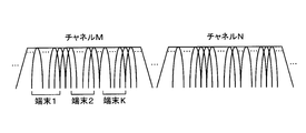
- FIG. 3 shows how a plurality of channels are arranged in the frequency domain.
- a guard band is provided between the channels.
- the bandwidth of one channel is 20 MHz, for example.
- the case where OFDMA communication is performed using a continuous band of one of the channels (here, channel M) corresponds to FIG.
- a plurality of subcarriers orthogonal to each other (for example, 52 in the case of the 20 MHz band) are arranged in a continuous band of the channel M (for example, 20 MHz wide band), and one or a plurality of continuous carriers are arranged based on these subcarriers.
- a resource block whose unit is a subcarrier to be assigned is allocated to terminal 1, terminal 2,...
- the bandwidth (or the number of subcarriers) for each resource block is common to each resource block, but the bandwidth (or the number of subcarriers) may be different for each resource block.
- the number of resource blocks allocated to each terminal is not limited to one resource block per terminal, and a plurality of resource blocks may be allocated to one terminal, and the number of resource blocks allocated to each terminal is different. May be.
- the resource block is composed of a plurality of subcarriers, the arrangement of subcarriers included in the resource block may or may not be continuous. It is also possible to assign a plurality of non-contiguous subcarriers as resource blocks to one terminal.
- At least one subcarrier is arranged as a guard subcarrier between resource blocks allocated to each terminal.
- the number of guard subcarriers arranged between resource blocks may be determined in advance by the system or specification, or may be determined arbitrarily. Moreover, it is not essential to arrange guard subcarriers between resource blocks, and it may be allowed not to arrange guard subcarriers between resource blocks.
- the number of channels used in OFDMA communication is not limited to one, and OFDMA communication can be performed using two or more channels.
- resource blocks may be allocated in each channel independently as described above.
- one terminal may be allowed to receive allocation of a plurality of resource blocks belonging to different channels.
- a continuous frequency region in which a plurality of channels are combined may be defined, and resource blocks may be allocated in the combined frequency region. For example, a 40 MHz frequency region may be defined by combining two 20 MHz wide channels adjacent in frequency, and resource blocks may be allocated based on mutually orthogonal subcarrier groups within the 40 MHz frequency region.
- resource blocks may be allocated based on subcarrier groups orthogonal to each other in each frequency domain.
- a terminal that implements OFDMA has at least a basic channel width of a legacy terminal that is subject to backward compatibility (20 MHz channel width if an IEEE 802.11a / b / g / n / ac standard-compliant terminal is a legacy terminal), It is assumed that a physical packet including a frame can be received and decoded (including decoding and demodulation of an error correction code).
- carrier sense is performed in units of channels.
- the carrier sense includes CCA (Clear Channel Asset) busy / idle physical carrier sense (Physical Carrier Sense) and virtual carrier sense based on the media reservation time described in the received frame (Virtual Carrier Sense). Sense) may be included.
- NAV Network Allocation Vector
- Carrier sense information based on CCA or NAV performed for each channel may be commonly applied to all resource blocks in the channel. For example, resource blocks belonging to a channel whose carrier sense information indicates idle may be processed as being idle by commonly applying the carrier sense information of the channel.
- the terminal according to the present embodiment is not limited to performing carrier sense on a channel basis, and if the terminal implements a mechanism that performs carrier sense on a resource block basis, carrier sense (physical sense on a resource block basis) (Both manual and virtual) may be allowed to be performed.
- OFDMA can be channel-based OFDMA in addition to the resource block-based OFDMA described above.
- the OFDMA in this case is sometimes called MU-MC (Multi-User Multi-Channel).
- MU-MC Multi-User Multi-Channel
- a base station assigns a plurality of channels to a plurality of terminals, and simultaneously uses the plurality of channels to simultaneously transmit to or receive from a plurality of terminals.
- a resource block-based OFDMA is assumed. Base OFDMA embodiments are also feasible.
- a communication method combining OFDMA and MU-MIMO (referred to as OFDMA & MU-MIMO) is also possible.
- OFDMA & MU-MIMO each of a plurality of resource blocks is assigned to a plurality of terminals, and MU-MIMO transmission is performed in resource block units simultaneously in each of the plurality of resource blocks.
- Both uplink OFDMA & MU-MIMO and downlink OFDMA & MU-MIMO are possible.
- OFDMA & MU-MIMO may be used.
- a terminal having the capability of implementing at least one of UL-OFDMA and UL-MU-MIMO may be referred to as a UL-MU terminal.
- a terminal that does not have this capability may be referred to as a legacy terminal.
- a terminal with the enabled capability may be considered as a UL-MU terminal.
- the UL-MU terminal may further include a capability to implement at least one of DL-OFDMA and DL-MU-MIMO.
- a terminal designated as a base station as a target of the current UL-MU communication corresponds to a UL-MU target terminal and is not designated as a target of the current UL-MU as a base station.
- the terminal corresponds to a non-target terminal of UL-MU.
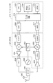
- a wireless communication device mounted on a terminal includes a host processing unit 90, a MAC processing unit 10, a PHY (Physical) processing unit 50, a MAC / A PHY management unit 60, an analog processing unit 70 (analog processing units 1 to N), and an antenna 80 (antennas 1 to N) are included.
- N is an integer of 1 or more.
- a pair of N analog processing units and N antennas are connected, but the present invention is not necessarily limited to this configuration.
- the number of analog processing units may be one, and two or more antennas may be commonly connected to the analog processing unit.
- the MAC processing unit 10, the MAC / PHY management unit 60, and the PHY processing unit 50 correspond to a form of a communication processing device or a baseband integrated circuit that performs processing related to communication with other terminals (including base stations).
- the analog processing unit 70 corresponds to, for example, a form of a wireless communication unit that transmits and receives signals via an antenna 80 or an RF (Radio Frequency) integrated circuit.
- the wireless communication integrated circuit according to the present embodiment may include at least the former of the baseband integrated circuit (communication processing device) and the RF integrated circuit.
- the functions of the communication processing device or the baseband integrated circuit may be performed by software (program) that operates on a processor such as a CPU, may be performed by hardware, or may be performed by both software and hardware. May be.
- the software may be stored in a storage medium such as a ROM or RAM, a hard disk, or an SSD, read by a processor, and executed.
- the memory may be a volatile memory such as a DRAM or a non-volatile memory such as a NAND or MRAM.
- the upper processing unit 90 performs processing for the upper layer on the MAC (Medium Access Control) medium layer.
- the host processing unit 90 can exchange signals with the MAC processing unit 10.
- Typical examples of the upper layer include TCP / IP, UDP / IP, and an upper application layer.
- the upper processing unit 90 may include a buffer for exchanging data between the MAC layer and the upper layer. You may connect with a wired infrastructure via the high-order process part 90.
- the buffer may be a memory, an SSD, a hard disk, or the like. When the buffer is a memory, the memory may be a volatile memory such as a DRAM or a nonvolatile memory such as a NAND or MRAM.
- the MAC processing unit 10 performs processing for the MAC layer. As described above, the MAC processing unit 10 can exchange signals with the host processing unit 90. Further, the MAC processing unit 10 can exchange signals with the PHY processing unit 50.
- the MAC processing unit 10 includes a MAC common processing unit 20, a transmission processing unit 30, and a reception processing unit 40. *
- the MAC common processing unit 20 performs processing common to transmission and reception in the MAC layer.
- the MAC common processing unit 20 is connected to the host processing unit 90, the transmission processing unit 30, the reception processing unit 40, and the MAC / PHY management unit 60, and exchanges signals with each other.
- the transmission processing unit 30 and the reception processing unit 40 are connected to each other.
- the transmission processing unit 30 and the reception processing unit 40 are connected to the MAC common processing unit 20 and the PHY processing unit 50, respectively.
- the transmission processing unit 30 performs transmission processing at the MAC layer.
- the reception processing unit 40 performs reception processing at the MAC layer.
- the PHY processing unit 50 performs processing for the physical layer (PHY layer). As described above, the PHY processing unit 50 can exchange signals with the MAC processing unit 10.
- the PHY processing unit 50 is connected to the antenna 80 via the analog processing unit 70.
- the MAC / PHY management unit 60 is connected to the host processing unit 90, the MAC processing unit 10 (more specifically, the MAC common processing unit 20), and the PHY processing unit 50.
- the MAC / PHY management unit 60 manages the MAC operation and the PHY operation in the wireless communication apparatus.
- the analog processing unit 70 includes an analog / digital and digital / analog (AD / DA) converter and an RF (Radio Frequency) circuit, converts the digital signal from the PHY processing unit 50 into an analog signal having a desired frequency, and an antenna. A high-frequency analog signal transmitted from the antenna 80 and received from the antenna 80 is converted into a digital signal.
- AD / DA conversion is performed by the analog processing unit 70, but a configuration in which the PHY processing unit 50 is provided with an AD / DA conversion function is also possible.
- the wireless communication apparatus includes (integrates) the antenna 80 as a constituent element in one chip, so that the mounting area of the antenna 80 can be reduced. Further, in the wireless communication apparatus according to the present embodiment, as illustrated in FIG. 1, the transmission processing unit 30 and the reception processing unit 40 share N antennas 80. Since the transmission processing unit 30 and the reception processing unit 40 share the N antennas 80, the wireless communication apparatus in FIG. 1 can be reduced in size. Of course, the wireless communication apparatus according to the present embodiment may have a configuration different from that illustrated in FIG.
- the analog processing unit 70 converts the analog signal received by the antenna 80 into a baseband signal that can be processed by the PHY processing unit 50, and further converts it into a digital signal.
- the PHY processing unit 50 receives a digital reception signal from the analog processing unit 70 and detects the reception level. The detected reception level is compared with the carrier sense level (threshold value). If the reception level is equal to or higher than the carrier sense level, the PHY processing unit 50 indicates that the medium (CCA: Clear Channel Assessment) is busy. Are output to the MAC processing unit 10 (more precisely, the reception processing unit 40). If the reception level is less than the carrier sense level, the PHY processing unit 50 outputs a signal indicating that the medium (CCA) is idle to the MAC processing unit 10 (more precisely, the reception processing unit 40). .
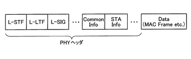
- the PHY processing unit 50 performs a decoding process (including decoding and demodulation of an error correction code) on the received signal, a process of removing a physical header including a preamble (PHY header), and the like to extract a payload.
- this payload is converted to PSDU (physical layer convergence procedure) on the PHY side. (PLCP) service data unit).
- PSDU physical layer convergence procedure
- the PHY processing unit 50 passes the extracted payload to the reception processing unit 40, and the reception processing unit 40 handles this as a MAC frame.
- this MAC frame is converted into MPDU (medium access control (MAC) protocol data). unit).
- MPDU medium access control
- the PHY processing unit 50 notifies the reception processing unit 40 when reception of the reception signal is started, and notifies the reception processing unit 40 when reception of the reception signal is completed.
- the received signal can be normally decoded as a physical packet (PHY packet) (if no error is detected)
- the PHY processing unit 50 notifies the reception end of the received signal and the medium is idle. Is sent to the reception processing unit 40.
- the PHY processing unit 50 notifies the reception processing unit 40 that an error has been detected with an appropriate error code corresponding to the error type.
- the PHY processing unit 50 determines that the medium has become idle, the PHY processing unit 50 notifies the reception processing unit 40 of a signal indicating that the medium is idle.
- the MAC common processing unit 20 mediates transmission of transmission data from the upper processing unit 90 to the transmission processing unit 30 and transmission of received data from the reception processing unit 40 to the upper processing unit 90, respectively.
- data in this MAC data frame is called MSDU (medium access control (MAC) service data unit).
- MSDU medium access control
- the MAC common processing unit 20 once receives an instruction from the MAC / PHY management unit 60, converts the instruction into a suitable one for the transmission processing unit 30 and the reception processing unit 40, and outputs them.
- the MAC / PHY management unit 60 corresponds to, for example, SME (Station Management Entity) in the IEEE 802.11 standard.
- SME Stim Management Entity
- the interface between the MAC / PHY management unit 60 and the MAC common processing unit 20 corresponds to MLME SAP (MAC subLayer Managment Access Point) in the IEEE 802.11 standard
- MLME SAP MAC subLayer Managment Access Point
- An interface with the processing unit 50 corresponds to a PLME SAP (Physical Layer Management Service Access Point) in an IEEE 802.11 wireless LAN (Local Area Network).
- the MAC / PHY management unit 60 is depicted as if the function unit for MAC management and the function unit for PHY management are integrated, but may be separately implemented. Good.
- the MAC / PHY management unit 60 holds a management information base (MIB).
- the MIB holds various information such as whether the capability and various functions of the terminal itself are valid or invalid. For example, whether or not the own terminal is a UL-MU compatible terminal, and in the case of a UL-MU compatible terminal, ON / OFF information of the function of the ability to implement UL-MU may be held.
- the memory for holding and managing the MIB may be included in the MAC / PHY management unit 60, or may be provided separately without being included in the MAC / PHY management unit 60.
- the MAC / PHY management unit 60 can refer to the other memory and rewrites rewritable parameters in the memory. It can be performed.
- the memory may be a volatile memory such as a DRAM or a non-volatile memory such as a NAND or MRAM. Further, not a memory but a storage device such as an SSD or a hard disk may be used.
- these pieces of information of other terminals as non-base stations can also be acquired by notification from the terminals. In that case, the MAC / PHY management unit 60 can refer to and rewrite information on other terminals.
- the MAC / PHY management unit 60 or the MAC common processing unit 20 can refer to / rewrite the other memory.
- the base station MAC / PHY management unit 60 assigns a terminal to which a resource block for UL-MU communication is simultaneously allocated based on various information related to a terminal as a non-base station or a request from the terminal when transmitting UL-MU.
- a grouping function for selecting (that is, selecting a terminal as a target of the current UL-MU) may be provided.
- the MAC / PHY management unit 60 or the MAC processing unit 10 may manage the transmission rate applied to the MAC frame to be transmitted and the physical header.
- the MAC / PHY management unit 60 of the base station may define a support rate set that is a rate set supported by the base station.
- the support rate set may include a rate required to be supported by a terminal connected to the local station and an optional rate.
- the MAC processing unit 10 handles three types of MAC frames, a data frame, a control frame, and a management frame, and performs various processes defined in the MAC layer.
- three types of MAC frames will be described.
- the management frame is used for management of communication links with other terminals.
- the management frame for example, there is a beacon frame that broadcasts group attributes and synchronization information in order to form a wireless communication group that is a Basic Service Set (BSS) in the IEEE 802.11 standard.
- BSS Basic Service Set
- a state where a certain terminal has exchanged information necessary for performing wireless communication with another terminal is expressed as a communication link established.
- Necessary information exchange includes, for example, notification of functions supported by the terminal (for example, support for UL-MU system, various capabilities described later, etc.) and negotiation for setting of the system.
- the management frame is generated based on an instruction received by the transmission processing unit 30 from the MAC / PHY management unit 60 via the MAC common processing unit 20.
- the transmission processing unit 30 has notification means for notifying other terminals of various information via the management frame.
- the notification means of the terminal as a non-base station transmits information indicating whether it is compatible with a UL-MU compatible terminal, an IEEE 802.11n compatible terminal, or an IEEE 802.11ac compatible terminal in a management frame.
- the station may be notified of the type of its own terminal.
- this management frame for example, there is an Association Request frame used in an association process, which is one of procedures for a terminal to authenticate with a base station, or a Reassociation Request frame used in a rear association process.
- the notification means of the base station may notify the non-base station terminal of information on availability of support for UL-MU communication via a management frame.
- Examples of the management frame used for this include a Beacon frame and a Probe Response frame that is a response to a Probe Request frame transmitted by a non-base station terminal.
- the base station may have a function of grouping terminal groups connected to its own device.
- the above notification means of the base station may notify the group ID of each group assigned to each terminal via a management frame.
- this management frame for example, there is a Group ID Management frame.
- the group ID may be, for example, a group ID defined in IEEE Std 802.11ac-2013.
- the base station may notify information necessary for identifying a resource block used by a terminal belonging to the group via an arbitrary management frame. Good.
- the reception processing unit 40 has receiving means for receiving various information from other terminals via management frames.
- the receiving unit of the base station may receive information on whether to support UL-MU communication from a terminal as a non-base station. Further, information on a channel width (maximum usable channel width) that can be handled when the terminal is a legacy terminal (such as a terminal that supports the IEEE 802.11a / b / g / n / ac standard) may be received.
- the receiving means of the terminal may receive information on availability of UL-MU communication from the base station.
- a UL-MU compatible terminal uses a resource block or channel that it desires to use for UL-MU transmission, or both, a channel that is non-interfering with carrier sense, or a resource block that is non-interfering, Or you may select from both of these. Then, information regarding the selected resource block and / or channel may be notified to the base station. In this case, the base station may perform resource block allocation for UL-MU communication to each UL-MU compatible terminal based on the information.
- the channels used in the UL-MU communication may be all channels that can be used as a wireless communication system, or some (one or more) channels.
- the data frame is used to transmit data to the other terminal in a state where a communication link is established with the other terminal.
- data is generated in the terminal by a user's application operation, and the data is carried by a data frame.
- the generated data is passed from the upper processing unit 90 to the transmission processing unit 30 via the MAC common processing unit 20, and the transmission processing unit 30 puts the data in the frame body field and adds a MAC header.
- a data frame is generated.
- the PHY processing unit 50 adds a physical header to the data frame to generate a physical packet, and the physical packet is transmitted via the analog processing unit 70 and the antenna 80.
- the physical layer is processed based on the physical header to extract a MAC frame (in this case, a data frame), and the data frame is passed to the reception processing unit 40.
- the reception processing unit 40 extracts the information of the frame body field as data, and the extracted data is passed through the MAC common processing unit 20. To the host processor 90. As a result, application operations such as data writing and reproduction occur.
- the control frame is used for control when the management frame and the data frame are transmitted / received (exchanged) to / from another wireless communication apparatus.
- As the control frame for example, before starting the exchange of the management frame and the data frame, an RTS (Request to Send) frame exchanged with another wireless communication device in order to reserve a wireless medium, a CTS (Clear to) Send) frame.
- As another control frame there is a delivery confirmation response frame for confirming delivery of the received management frame and data frame. Examples of the delivery confirmation response frame include an ACK (Acknowledgement) frame and a BA (BlockACK) frame. Since the CTS frame is also transmitted as a response to the RTS frame, it can be said that the CTS frame represents a delivery confirmation response.
- the CF-End frame is also one of the control frames.
- the CF-End frame is a frame that announces the end of CFP (Contents Free Period), that is, a frame that permits access to the wireless medium.
- These control frames are generated by the transmission processing unit 30.
- the reception processing unit 40 determines whether the response frame (control frame) needs to be transmitted and generates a frame.
- Necessary information (control frame type, information set in the RA field, etc.) is output to the transmission processing unit 30 together with a transmission instruction.
- the transmission processing unit 30 generates an appropriate control frame based on information necessary for generating the frame and a transmission instruction.
- the MAC processing unit 10 needs to acquire an access right (transmission right) on a wireless medium when transmitting a MAC frame based on CSMA / CA (Carrier Sense Multiple Access With Carrier Avidance).
- the transmission processing unit 30 measures transmission timing based on the carrier sense information from the reception processing unit 40.
- the transmission processing unit 30 gives a transmission instruction to the PHY processing unit 50 according to the transmission timing, and passes the MAC frame.
- the transmission processing unit 30 may instruct the modulation scheme and the encoding scheme used for transmission together. In addition to these, the transmission processing unit 30 may instruct transmission power.
- the MAC processing unit 10 After obtaining the access right (transmission right), the MAC processing unit 10 is able to occupy the medium (Transmission Opportunity; TXOP), and other wireless communication is performed, although there are restrictions on QoS (Quality of Service) attributes and the like.
- MAC frames can be exchanged continuously with the device.
- TXOP for example, a wireless communication apparatus transmits a predetermined frame (for example, an RTS frame) based on CSMA / CA (Carrier Sense Multiple Access with Carrier Avoidance), and a response frame (for example, a CTS frame) is correctly transmitted from another wireless communication apparatus. Earned when received.
- the other wireless communication device transmits the response frame after a minimum frame interval (short interframe space; SIFS).
- SIFS short interframe space
- a data frame that directly requests transmission of a delivery confirmation response frame by unicast (a frame having a shape in which frames are concatenated as described later, or a payload is concatenated).
- a management frame may be transmitted, and a delivery acknowledgment response frame (ACK frame or BlockACK frame) may be received correctly.
- Duration field a Duration / ID field of the frame. May be interpreted as having acquired a TXOP for the period described in the Duration field from the stage of transmitting the frame.
- the reception processing unit 40 manages the carrier sense information described above.
- the carrier sense information is managed for each channel, for example.
- This carrier sense information is based on the physical carrier sense information regarding busy / idle of the medium (CCA) input from the PHY processing unit 50 and the medium reservation time described in the received frame. Includes both virtual carrier sense information. If any one of the carrier sense information indicates busy, the medium is considered busy and transmission is prohibited during that time.
- the medium reservation time is described in the Duration field in the MAC header.
- NAV Network Allocation Vector
- the data frame may be configured to connect a plurality of MAC frames or payload portions of a plurality of MAC frames.
- the former is called A (Aggregated) -MPDU in the IEEE 802.11 standard, and the latter is called A (Aggregated) -MSDU (MAC service data unit).
- A-MPDU a plurality of MPDUs are connected in PSDU.
- management frames and control frames are also subject to concatenation.
- a plurality of data payloads MSDU are connected in a frame body of one MPDU.
- delimiter information (length information, etc.) is stored in the data frame so that the concatenation of multiple MPDUs and the concatenation of multiple MSDUs can be properly separated at the receiving terminal.
- a combination of both A-MPDU and A-MSDU may be used.
- the A-MPDU may target only one MAC frame instead of a plurality of MAC frames, and in this case, the delimiter information is stored in the data frame.
- the data frame is an A-MPDU or the like, responses for a plurality of MAC frames are transmitted together.
- a BA (BlockACK) frame is used instead of an ACK frame.
- MPDU notation may be used, but this includes not only a single MAC frame but also the above-described A-MPDU or A-MSDU.
- a non-base station terminal joins a BSS (this is called an infrastructure BSS) formed mainly by a base station, and data frames can be exchanged within the BSS.
- a plurality of procedures are defined in stages. For example, there is a procedure called association, and a non-base station terminal transmits an association request frame to a base station to which the terminal requests connection.
- the base station transmits an ACK frame for the association request frame, and then transmits an association response frame that is a response to the association request frame.
- the terminal stores the capability of its own terminal in the association request frame, and can notify the base station of the capability of its own terminal by transmitting it.
- a terminal transmits a channel or resource (resource block or stream) that can be supported by the terminal in the association request frame, or both of them, and information for specifying a standard that the terminal supports. Also good.
- This information may also be included in a frame that is transmitted in a procedure called reassociation for reconnection to another base station.
- a reassociation request (Reassociation Request) frame is transmitted from the terminal to another base station that requests reconnection.
- the other base station transmits an ACK frame for the reassociation request frame, and then transmits a reassociation response frame that is a response to the reassociation request frame.
- a beacon frame in addition to the association request frame and the reassociation request frame, a beacon frame, a probe response frame, or the like may be used.
- the beacon frame is basically transmitted by the base station, and can store a parameter indicating the BSS attribute and a parameter notifying the base station itself. Therefore, the base station may add information indicating whether or not the base station can cope with UL-MU communication as a parameter for reporting the capability of the base station itself. Moreover, you may notify the information of the support rate (Supported Rate) of a base station as another parameter.
- the support rate may include a mandatory rate and an optional rate.
- the base station transmits the capability (UL- Notification of support for MU communication, support rate, etc.).
- the terminal can also enable the UL-MU communication function of its own terminal, for example.
- the terminal may notify information on a rate that can be executed by the terminal among the support rates of the base station as information to notify the base station of the capability of the terminal.
- an indispensable rate among the support rates it is assumed that a terminal connected to the base station has an ability to execute the indispensable rate.
- the notification can be omitted if there is information that is indispensable by notifying other information among the information handled above. For example, if a capability corresponding to a new standard or specification is defined, and if it corresponds to it, it is a terminal supporting UL-MU itself, then notification that it is an IFDMA compatible terminal must be explicitly not performed. Also good.
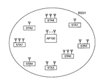
- FIG. 4 shows a wireless communication system according to the present embodiment.
- This system includes a base station (AP: Access Point) 100 and a plurality of terminals (STA: STATION) 1-8.
- the base station 100 and the terminals 1 to 8 under its control form a BSS (Basic Service Set) 1.
- BSS Basic Service Set
- This system is a wireless LAN system conforming to the IEEE 802.11 standard using CSMA / CA (Carrier Sense Multiple Access with Carrier Avidance).
- legacy terminals such as IEEE802.11a / b / g / n / ac standard compatible terminals
- UL-MU terminal may exist in the BSS1.
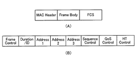
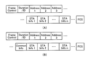
- FIG. 5A shows a basic format example of the MAC frame.
- the data frame, management frame, and control frame basically have such a frame format.
- This frame format includes fields of a MAC header (MAC header), a frame body (Frame body), and an FCS.
- the MAC header includes Frame Control, Duration / ID (sometimes referred to simply as Duration), Address1, Address2, Address3, Sequence Control, QoS Control, and HT (High Thr). Contains fields.
- an Address4 field may further exist.
- a notification field (or may be called a control field) may exist as a field or a subfield in the MAC header.
- the Address 1 field contains the recipient address (Receiver Address; RA), the Address 2 field contains the source address (Transmiter Address; TA), and the Address 3 field contains the BSS identifier according to the frame usage.
- BSSID Basic Service Set IDentifier
- Frame Control field two fields of type (Type) and subtype (Subtype) are set as described above.
- Data frames, management frames, and control frames are roughly classified in the Type field, and detailed classification among the roughly classified frames, for example, identification of BA frames, BAR frames, and Beacon frames in management frames is performed. This is done in the Subtype field.
- the Duration / ID field describes the medium reservation time.
- the medium is virtually transmitted from the end of the physical packet including the MAC frame to the medium reservation time. Is determined to be busy.
- the mechanism for determining that the medium is virtually busy, or the period during which the medium is virtually busy is called NAV (Network Allocation Vector) as described above.
- the QoS field is used for performing QoS control in which transmission is performed in consideration of frame priority.
- the HT Control field is a field introduced by IEEE802.11n, and exists when the order field is set to 1 in a QoS data frame or a management frame.
- the HT Control field can be extended to the IEEE 802.11ac VHT (Very High Throughput) Control field, the next generation wireless LAN standard IEEE 802.11ax HE (High Efficiency) Control field E, and each E Notification according to various functions of IEEE802.11ac or IEEE802.11ax can be made.
- IEEE 802.11ac VHT Very High Throughput
- IEEE 802.11ax HE High Efficiency Control field E
- an information element (Information element; IE) assigned with a unique Element ID (IDentifier) is set in the Frame Body field.
- IE Information element
- IDentifier a unique Element ID
- the information element includes an Element ID field, a Length field, and an Information field.
- the information element is identified by an Element ID.
- the information field stores the content of information to be notified, and the Length field stores length information of the information field.
- a notification field (control field) described later may be set in the body field of the management frame. In this case, the notification field may have the form of an information element.
- FCS Full Check Sequence
- CRC Cyclic Redundancy Code
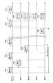
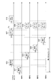
- FIG. 7 shows an example of an operation sequence between the base station (AP) 101 according to the present embodiment and a plurality of terminals including the terminal (STA) 1 to the terminal (STA) 4.
- a plurality of terminals including the terminals 1 to 4 are UL-MU compatible terminals.
- terminals other than the terminals 1 to 4 are not shown, but actually, other terminals 5 to 8 may exist as shown in FIG.
- a short section indicated by a solid line with a double-pointed arrow represents a short interframe space (SIFS).
- SIFS short interframe space
- the section to which reference sign T1 is attached represents SIFS or other fixed time (IFS).
- Sections 501A, 503A, and 505A indicated by bold arrows represent the sum of the DIFS / AIFS [AC] time and the CSMA / CA backoff (BackOff) time (carrier sense time or standby time).
- the SIFS and DIFS / AIFS [AC] time is an example, and another time (IFS) may be used as long as it is a predetermined time.
- the DIFS / AIFS [AC] time means the time of either DIFS or AIFS [AC]. When it is not compatible with QoS, it indicates DIFS time, and when it is compatible with QoS, it indicates AIFS [AC] time determined according to an access category (AC) (to be described later) of data to be transmitted.
- communication is performed individually with a basic channel width (or a combined bandwidth of a plurality of channels) between the base station and individual terminals including the terminals 1 to 4.
- the base station determines the start of UL-MU (UL-OFDMA or UL-MIMO) transmission.
- the base station decides to start UL-MU transmission, it transmits a trigger frame (more specifically, a physical packet including the trigger frame) 507 that triggers UL-MU transmission, and terminals 1 to 4 receive the trigger frame.
- Data frames (more specifically, physical packets including data frames) 509, 510, 511, and 512 are transmitted after a certain time T1. Thereby, UL-MU transmission from the terminals 1 to 4 to the base station is performed.
- the terminal 1 transmits a data frame (more specifically, a physical packet including a data frame) 501 including data to be transmitted, and when the base station normally receives the data frame 501, the SIFS time from the completion of reception of the data frame 501 Later, an ACK frame (more specifically, a physical packet including an ACK frame) 502 which is a delivery confirmation response frame is returned.
- the terminal 1 receives the ACK frame 502 and determines that the data frame 501 has been successfully transmitted.
- the data frame to be transmitted to the base station may be an aggregation frame (A-MPDU or the like), and the delivery confirmation response frame to which the base station responds may be a BA frame (the same applies hereinafter).
- the terminal 2 acquires the access right and transmits the data frame 503, and the base station transmits the ACK frame 504 after SIFS time from the completion of reception of the data frame 503.
- the terminal 3 obtains the access right and transmits the data frame 505, and the base station transmits the ACK frame 506 after SIFS time from completion of reception of the data frame 505.
- the example in the figure shows an example in which only the terminals 1 to 3 transmit data frames to the base station, but the terminal 4 and the terminals 5 to 8 (not shown) may exchange frames in the same manner.
- the communication is performed in the order of the terminal 1, the terminal 2, and the terminal 3. However, this is only the order in which the access right is acquired, and the communication may be performed in any order.
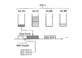
- each terminal transmits notification information (or may be referred to as control information) that is information necessary for the UL-MU to the notification field (control information). Field). That is, the data frame has a role of transmitting notification information necessary for the UL-MU in addition to the role of transmitting the data to the base station.
- the data frame includes information (the above data) for a purpose different from the notification information in the frame body field.
- the notification information can be set not only in a data frame transmitted by a single user but also in a data frame transmitted by UL-MU.
- Examples of the notification information include information on the presence / absence of a UL-MU transmission request, information on the presence / absence of data desiring UL-MU transmission, and information on the data type of data desiring UL-MU transmission.
- information such as the number and / or size of data regarding the data amount of data desired to be transmitted by UL-MU.
- there is a desired communication method either OFDMA or MU-MIMO communication method.
- the desired resource resource block in OFDMA, stream in MU-MIMO
- the desired resource may be specified by a resource number or a stream number, or may be specified by other methods.
- the notification information may include at least one of information in the example described here, or may include information of a type not described here.
- the notification information is spontaneously transmitted from each terminal in a state in which no notification information transmission request is made from the base station. That is, the notification information is transmitted in the form of sharing the frame transmitted by each terminal with the normal single user communication.
- the notification field for setting the notification information may be provided as a new field in the MAC header as shown in FIG.
- a reserved area in an existing field (a field defined by an existing standard) may be used as a notification field.
- the notification field may be provided in the physical header, or a reserved area in an existing field in the physical header may be used as the notification field.
- the notification field may be set not in the MAC header but in the body field of the frame. For example, when the data frame transmitted to the base station is an A-MPDU, one of a plurality of MAC frames stored in the payload of the data frame may be used as a management frame, and the frame body field of the management frame may be used as a notification field. .
- the notification field may have the information element format as previously shown in FIG. 6, and a new element ID may be assigned to the information element that sets the notification field. . Also, a new value may be defined for the frame including the notification field as a subtype of the Frame Control field.
- the information element of the notification field may be additionally set in the frame body of the existing management frame. The specific format of the notification field depends on the content of notification information to be set.
- the notification information notified by each terminal in the notification field will be described.
- the notification information is used by the base station for scheduling including determination of necessary items of UL-MU.
- notification information there is information on whether or not there is a request for UL-MU transmission. If the remaining data to be transmitted to the base station exists in the transmission buffer (transmission queue), it can be said that there is a request for UL-MU transmission.
- 1 bit may be used. When bit 1 is set, a UL-MU transmission request may be issued. When bit 0 is set, there may be no UL-MU transmission request. Alternatively, the bit relationship may be reversed.
- the base station when selecting a UL-MU transmission target terminal, the base station may select a terminal having a UL-MU transmission request.
- the more data field used for notifying the terminal in the power save mode of the presence / absence of the remaining data for downlink may be used as the notification information of the first example.
- the presence of data for transmission may be notified by setting the bit of the more data field to 1.
- a method of not providing a notification field is also possible.
- the terminal has data to be transmitted to the base station, there may be a situation where it is desired to transmit by single user transmission without transmitting by UL-MU transmission.
- UL-MU transmission a resource (for example, one channel bandwidth) is shared by a plurality of terminals, so that the frame length (physical) when sending the same data size is compared with single user transmission in which one terminal can use one channel bandwidth. (Packet length) becomes longer.
- Packet length As the frame length increases, the possibility of transmission failure (for example, the possibility of detecting a frame error on the receiving side) increases accordingly.
- the terminal wants to transmit reliably, there may be a situation where the user does not want to perform the UL-MU transmission but performs the single user transmission. In such a case, the terminal sets information indicating that there is no request for transmission (there is no remaining data) in the notification field, and the data can be transmitted as a single user on a CSMA / CA basis as usual. Good.
- the notification information information for specifying the presence or absence of a UL-MU transmission request for each data type in the terminal (that is, the presence or absence of data for UL-MU transmission for each data type) may be used.
- the data type may be IEEE 802.11 standard TID (Traffic ID) or AC (Access Category). The following description will be based on AC as the data type, but TID may be used instead (the same applies to the description of the third and subsequent examples of notification information).
- EDCA Enhanced Distributed Channel Access
- A access category
- EDCA Enhanced Distributed Channel Access
- the wireless LAN of the IEEE 802.11 standard when data is transferred from an upper layer (LLC layer or the like) to the MAC layer, if the terminal supports QoS (Quality of Service), the traffic type (TID) is set together with the data. Be notified.
- QoS Quality of Service
- TID traffic type
- IEEE 802.11n and IEEE 802.11ac compatible terminals support QoS.
- the data is classified into four ACs based on the traffic type, for example.
- TID values 0 to 15 exist, 0 to 7 are used in terminals (including base stations) in an EDCA environment, and 8 to 15 are HCCA (hybrid coordination function (HCF) controlled channel access (HCCA)) environment or a terminal in an HEMM (HCCA, EDCA mixed mode) environment (including base stations).
- HCF hybrid coordination function
- HCCA hybrid coordination function
- HCCA hybrid coordination function controlled channel access
- HEMM HEMM
- EDCA mixed mode including base stations
- a transmission buffer (transmission queue) is provided for each of the four ACs, and the classified data is stored in the corresponding transmission buffer.
- the transmission buffer may be a memory, an SSD, a hard disk, or the like.
- the transmission buffer is a memory
- the memory may be a volatile memory such as a DRAM or a nonvolatile memory such as a NAND or MRAM.
- EDCA parameter is defined for each AC, and the difference in the priority of medium access at the time of transmission is determined by this parameter.
- parameters include AIFS [AC], and a minimum value CWmin and a maximum value CWmax of a contention window (Content Window: CW).
- AIFS [AC], CWmin, and CWmax are set to smaller values as the medium access priority is higher.
- TXOP limit is the upper limit value of TXOP.
- the procedure for data transmission based on CSMA / CA is performed independently for each AC having data for transmission. That is, for each AC, carrier sense is performed during the standby time including AIFS [AC] and the back-off time, and the AC whose standby time becomes zero first acquires the access right. If there are a plurality of ACs whose standby times simultaneously become zero, an AC with a high medium access priority obtains an access right.
- the back-off time (random time) is obtained by multiplying an integer randomly selected from the contention window (Content Window: CW) by the slot time.
- the initial value of CW is given by CWmin, and every time retransmission is performed, the value of CW is increased until it reaches CWmax.
- FIG. 9 shows an example of a format indicating the presence / absence of a UL-MU transmission request for each AC (presence / absence of data for UL-MU transmission).
- One bit is provided for each of BACKGROUND (AC_BK), BEST EFFORT (AC_BE), VIDEO (AC_VI), and VOICE (AC_VO).
- Bit 1 can be set when data exists in the transmission queue corresponding to each of these ACs, and 0 can be set when there is no data. Alternatively, the bit relationship may be reversed. In this example, four bits are required to indicate the presence / absence of data for transmission of each AC.
- FIG. 10 shows a specific operation example for notifying the presence / absence of data for transmission of each AC using the format of FIG.
- a transmission queue is provided for each AC, and there is one MSDU (may be MPDU, PSDU, or PPDU) in the transmission queue of AC_VO.
- Two MSDUs exist in the AC_VI transmission queue, no MSDU exists in the AC_BK transmission queue, and one MSDU exists in the AC_BE transmission queue.
- the size of each MSDU does not need to be the same, and the size of the MSDU is different between ACs in the illustrated example. Assume that the procedure according to CSMA / CA is started independently for each AC at the time of transmission, and AC_VO first reaches the waiting time of zero and acquires the access right.
- the MSDU at the head of the AC_VO transmission queue is read, and the transmission queue becomes empty.
- a body field of the MAC frame is generated based on the read MSDU, and a MAC frame is generated by adding a MAC header to the body field.
- information indicating the presence / absence of remaining data for transmission is set for each AC in the notification field of the MAC header. Since the transmission queue of AC_VO is empty, bit 0 is present, and MSDU is present in the transmission queue of AC_VI (two). Therefore, bit 1 is present because the transmission queue of AC_BK is empty. Therefore, bit 1 is set in the corresponding subfield.
- the generated MAC frame is transmitted to the base station in a TXOP based on the acquired access right.
- the terminal 1 receives a delivery confirmation response frame (such as a BA frame or an ACK frame) from the base station after SIFS time from the transmission of the MAC frame.
- a transmission priority (distinguishable from the medium access priority described above) may be set for each AC. For example, the priority of “high”, “medium”, and “lower” may be set for each AC. Less or more than three priorities may be defined. If there is no data for transmission, the transmission priority may be set to “down”, or a priority such as “none” indicating that there is no data for transmission may be defined separately. Good.
- the third example may be combined with the second example to define notification information. In this case, the presence / absence of data for transmission and the priority of transmission are set for each AC.
- an AC that is most desired to transmit data that is, an AC that has the highest transmission priority may be specified.
- 2 bits are required to specify one of these four ACs.
- “00” may be specified for AC-VO, “01” for AC-VI, “11” for AC-BK, and “10” for AC-BE.
- the fourth example may be combined with the second example to define the notification information.
- a bit indicating the presence / absence of data transmission for example, 4 bits
- a bit (for example, 2 bits) designating one AC in this example are required.
- the amount of data may be the number of data (in this case, MSDU, but may be PPDU, or other PDU or SDU) existing in the transmission queue for each AC, the size of each MSDU, or both of them. .
- the total data size of the MSDU remaining in the transmission queue may be used.
- not the size but the time length may be used. Any information other than those described here may be used as long as the data amount can be specified. For example, when transmission is performed by transmission of an aggregation frame (A-MPDU, A-MSDU, or the like), information on how many aggregation frames exist may be used.
- the quantization method used when expressing the data amount may be any method.
- the basic unit may be 32 ⁇ s, which is a time length, and the data amount may be represented by an integer multiple of 32 ⁇ s.
- the field length for setting the data amount is 8 bits, for example, 32 ⁇ s to 8160 ⁇ s can be expressed.
- 32 ⁇ s is an example, and other lengths of time may be used as the basic unit.
- 8 bits is an example, and other field lengths may be used.
- the basic unit may be 4096 octets as the size, and the data amount may be expressed by an integer multiple of 4096 octets.
- the field length for setting the data amount is 4 bits and the field value is 1, it represents 4096 octets, and when it is 2, 8192 octets are represented. If the actual data amount does not match an integer multiple of 4096 octets, the closest value may be adopted that is larger than the actual data amount. A field value of 15 may indicate that the amount of data is greater than 57344 octets. Note that 4096 octets are an example, and other sizes may be used as the basic unit. Also, 4 bits is an example, and other field lengths may be used.
- information for specifying the amount of data for transmission (not by AC) in the terminal may be used.
- the number of transmission data in this case, MSDU, but may be PPDU, other PDU or SDU
- the size of each MSDU or these Both are good.
- the total size of MSDUs remaining for transmission may be used, or information other than that described here may be used.
- not the size but the time length may be used. Any information other than those described here may be used as long as the data amount can be specified. For example, when transmission is performed by transmission of an aggregation frame (A-MPDU, A-MSDU, or the like), information on how many aggregation frames exist may be used.
- A-MPDU aggregation frame
- A-MSDU aggregation frame
- the quantization method used when expressing the data amount may be any method.
- the basic unit may be 32 ⁇ s, which is a time length, and the data amount may be represented by an integer multiple of 32 ⁇ s.
- the field length for setting the data amount is 8 bits, for example, 32 ⁇ s to 8160 ⁇ s can be expressed.
- 32 ⁇ s is an example, and other lengths of time may be used as the basic unit.
- 8 bits is an example, and other field lengths may be used.
- the basic unit may be 4096 octets as the size, and the data amount may be expressed by an integer multiple of 4096 octets.
- the field length for setting the data amount is 4 bits and the field value is 1, it represents 4096 octets, and when it is 2, 8192 octets are represented. If the actual data amount does not match an integer multiple of 4096 octets, the closest value may be adopted that is larger than the actual data amount. A field value of 15 may indicate that the amount of data is greater than 57344 octets. Note that 4096 octets are an example, and other sizes may be used as the basic unit. Also, 4 bits is an example, and other field lengths may be used.
- information for specifying the TXOP length necessary for the next transmission may be used for all or part of ACs.
- the TXOP length may be represented by an integral multiple of 32 ⁇ s, for example, where the basic unit is 32 ⁇ s.
- the field length for setting the TXOP length is 8 bits, for example, 32 ⁇ s to 8160 ⁇ s can be expressed. Note that 32 ⁇ s is an example, and other lengths of time may be used as the basic unit. Also, 8 bits is an example, and other field lengths may be used.
- the data amount required for the next transmission may be used for all or a part of the AC.
- the data amount may be a data length such as PPDU or MSDU.
- the method of expressing the data amount is the same as the notification information in the fifth or sixth example.
- the information for specifying the TXOP length or the data amount necessary for the next transmission is shown for each AC.
- the information for specifying the TXOP length or the data amount necessary for the next transmission in the terminal is not shown for each AC. It may be information.
- the notification information it may be information on whether the terminal desires OFDMA or MU-MIMO (which may be MU-MIMO & OFDMA as described above, and so on). If the terminal is compatible with only one of the communication methods and the base station has been notified of the communication method that the terminal can support at the time of the association process or the like, the notification of this information may be omitted.
- information indicating the desired resource (resource block in OFDMA, stream in MU-MIMO) or the number of resources is indicated according to the UL-MU communication scheme (OFDMA or MU-MIMO). It may be information or both.
- the desired resource may be specified by the resource number or the stream number, or by another method.
- a desired resource may be specified by specifying a range of resource numbers. For example, when there are resource numbers 1 to 8, a range such as “resource numbers 6 to 8” may be designated. At this time, a plurality of ranges may be designated.
- the various types of notification information shown in the first to ninth examples described above are used independently, and may be used in any combination as long as there is no contradiction.
- the notification information may be defined by combining both the first example and the second example. Three or more pieces of notification information may be combined.
- the first to ninth examples are examples, and information other than these can be used as the notification information.
- information representing a data generation cycle in the terminal may be used.
- the generation cycle may be the above-described information for each AC or TID.
- the information which represents the value of the communication delay (allowable delay) permitted by the application in a terminal may be sufficient.
- TSPEC Traffic Specification
- MSDU length for example, average data rate, MSDU length, minimum physical rate, etc.
- minimum physical rate for example, average data rate, MSDU length, minimum physical rate, etc.
- some or all of the notification information may be set using an existing field such as a QoS Control field.
- a reserved area in an existing field may be used.
- the existing field has a plurality of pattern formats, a new pattern for setting notification information is newly defined, and a new pattern format is set.
- Notification information may be set in.
- existing field values themselves as notification information.
- the format of the QoS Control field differs depending on the subtype of the Frame Control field, but includes a TID subfield and a TXOP Duration Requested subfield as an example.
- the TID subfield the TID of the currently transmitted data is set, and in the TXOP Duration Requested subfield, a value necessary for the next TXOP is set.
- the values of these subfields may be used as notification information.
- the base station stores the notification information notified from each terminal in the notification field in an internal storage device, and manages the notification information for each terminal, thereby managing the state for each terminal.
- notification of notification information in the notification field includes a case where an existing field is used.
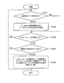
- the base station determines to perform UL-MU transmission at an arbitrary timing, a predetermined timing, or a timing when a predetermined condition is satisfied.
- the predetermined timing may be a certain beacon interval period or other timing.
- As a predetermined condition there may be a certain number or more of terminals having hope of UL-MU transmission, and radio wave conditions (busy rate, usage rate, or other indicators) satisfy a predetermined standard. You may require that.
- the base station may determine to perform UL-MU transmission independently of reception of data frames transmitted from the terminals 1 to 4 as a single user.
- a target terminal for UL-MU transmission is selected.
- selection may be made from a terminal having a request for UL-MU transmission.
- the terminal may be selected from terminals having transmission data of a specific data type (such as AC or TID).
- the target terminal may be selected based on the data amount or the TXOP length or data amount necessary for the next transmission, such as selecting a terminal (details will be described later).
- the terminal may be selected based on the transmission priority of the specific data type, such as the terminal having the highest transmission priority of the specific data type. Further, when the base station groups terminals, terminals belonging to the same group may be selected. In addition, as a criterion for selecting a group, items such as presence / absence of a UL-MU transmission request for each terminal belonging to each group, a data amount or priority of a specific data type, and the like may be considered. Alternatively, the selection method may be a round robin method or a random selection method.
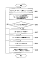
- a combination of terminals with small spatial correlation small interference
- the number of terminals to be selected is within a range that is less than or equal to the maximum number that can be multiplexed, depending on the communication method. In the case of OFDMA, the maximum number of usable resource blocks is selected.
- the range is selected within the range of the maximum number of available spatial resources (maximum number of streams).
- the lower limit of the number of terminals to be selected is determined, and the number of terminals that are greater than or equal to the lower limit may be selected.
- the base station allocates resources to be used for UL-MU transmission to the selected target terminal.
- the resource is a resource block (one or a plurality of subcarriers) in the case of OFDMA, and a spatial resource (stream) in the case of MU-MIMO.
- resource allocation resources are allocated so as not to overlap between target terminals.
- resources that can be used for each terminal are determined in advance (for example, when determined at the time of association with the base station or at an arbitrary timing thereafter, or depending on the capability of the terminal, the resources that can be used are If it has been determined, etc.), a predetermined resource is allocated.
- the target terminal may be selected so that the resources that can be used for each terminal are taken into consideration and the resources that can be used between the terminals do not overlap.
- the base station may determine the PPDU length transmitted by the target terminals in common. For example, when notification information including the TXOP length and / or data amount necessary for the next transmission is received from the target terminal, the TXOP length or data amount (PPDU length or the like) notified from the target terminal is used. Thus, the PPDU length may be determined. For example, the PPDU length may be determined based on the longest TXOP or data amount among the target terminals. Details are described in the description of trigger frame generation.
- the base station when selecting the target terminal, allocating resources, and determining other parameter information, if the notification information is notified from the terminal via the existing field, is stored in the existing field Scheduling may be performed using information.
- the base station generates a trigger frame 507 when the implementation details of the UL-MU communication such as the UL-MU communication target terminal and the resources allocated to the target terminal are determined.
- the trigger frame 507 may be defined based on the general MAC frame format shown in FIG.
- the type of the Frame Control field may be a value representing a control frame
- the value of the subtype may be a newly defined value for the trigger frame.
- the frame type of the trigger frame is not a control frame but a management frame or a data frame is not excluded.
- the value of the existing standard may be used as the value of the subtype.
- information necessary for the role of the trigger frame 507 may be added as an information element to the frame body field of an existing management frame.
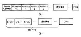
- the RA (reception destination address) of the trigger frame 507 may be a broadcast address or a multicast address, and the address may be set in the address 1 field.
- the TA (source address) may be the base station MAC address or BSSID.
- the number of terminal information fields (STA Info. Field) corresponding to the number of UL-MU transmission target terminals is set as shown in FIG.
- STA info fields four terminal information fields (STA info fields) 1 to 4 are set.
- each terminal information field information individually notified to the terminal is set. An example of information set in the terminal information field is shown below.
- the identifier of the selected terminal is set in the terminal information field.
- the terminal identifier may be a MAC address of the terminal, an association ID (AID), or an ID unique among terminals.
- parameter information used individually by the terminal when transmitting UL-MU may be set.
- An example of parameter information is shown below.
- parameter information there is at least one of a data length that permits transmission, an error correction code scheme, PHY or MAC, or MCS (Modulation and Coding Scheme) that specifies both transmission rates.
- the data length may be the physical packet length, or may be the MAC frame length or the MSDU length if the physical header length is fixed, or the length of the other part.
- the unit of the data length may be a data size or a time length (occupied time length in space).
- the data length may be common to each terminal or may be different for each terminal.
- the maximum value of the data length (PPDU length or the like) may be determined in advance by a standard or system, and in this case, the data size is specified within a range equal to or less than the maximum value.
- the base station When determining the data length (for example, PPDU length) in the base station, for example, the largest PPDU length among the target terminals may be estimated or calculated, and the PPDU length of the terminal may be set as the uplink transmission data length. . Further, when selecting the target terminal, the base station may select terminals having the same or close PPDU length based on the PPDU length requested by the terminal. If the PPDU length transmitted for each terminal is different, the resources allocated to the terminal with the short PPDU length are wasted after the transmission of the terminal with the short PPDU length is completed until the transmission of the terminal with the long PPDU length is completed. Efficiency may also decrease. Therefore, it is possible to increase system efficiency by selecting a terminal having a short PPDU length.
- the data length for example, PPDU length
- the base station may determine the MCS for each target terminal so that the PPDU lengths of the target terminals performing UL-MU communication are equal or close to each other, and specify the MCS information in the terminal information field. For example, even if the data size is the same, if the applied MCS is different, the occupation time length is different. Therefore, when the data size is different in each terminal, the occupied time length of the PPDU in each terminal may be the same or close by adjusting the MCS.
- the MCS may designate the MCS for the field of the physical header when the MCS can be designated for some or all of the fields of the physical header.
- information on the data type to be transmitted by each terminal may be specified.
- Information of access category (AC) or traffic information (TID: Traffic ID) may be set as the data type.
- the data type to be specified may be different for each terminal or may be common to each terminal.
- a plurality of data types may be specified for one terminal.
- information on the UL-MU communication method may be specified.
- the base station adopts a mechanism capable of specifying either OFDMA or MU-MIMO and allowing the terminal to transmit UL-MU
- information specifying either OFDMA or MU-MIMO is specified.
- the terminal performs UL-MU transmission using the communication method specified by the trigger frame.
- the base station acquires a communication method that can be supported by the terminal at the time of the association process with the terminal or at an arbitrary timing thereafter, and selects the target terminal from the terminals corresponding to the communication method to be used. Good.
- information specifying one or more resources allocated to a terminal may be set in the terminal information field according to the UL-MU communication method to be used.
- information specifying one or more resource blocks assigned to a terminal may be set in the terminal information field.
- the format for specifying the resource block may be any format as long as the resource block can be specified. For example, it may be specified by a resource block number. The number of the resource block from the high frequency side or the low frequency side may be specified.
- information specifying a stream allocated to a terminal for example, information on a pattern of a preamble (a preamble for estimating a channel response) added to a frame may be specified.
- the preamble of each terminal is selected so as to be orthogonal to each other (details will be described later).
- the number of streams permitted to the terminal may be specified. It is assumed that the number of streams that can be handled by the terminal has been acquired by the base station in advance as capability information of the terminal.
- a common information field for notifying information (Common Information) between target terminals may be provided in the frame body field of the trigger frame, as shown in FIG. 11B.
- Information commonly notified to the target terminals is set. For example, when the transmission data size designated for each terminal is common, it may be set in the common information field instead of the terminal information field. Further, the UL-MU communication method to be used may be set in the common information field instead of the terminal information field.
- the group ID of the group may be specified in the common information field.
- the terminal information field and the common information field are set in the frame body field.
- part or all of the information set in the terminal information field and the common information field may be arranged in the MAC header.
- part or all of the information set in the terminal information field and the common information field may be arranged in the physical header as shown in FIG.
- the physical header in FIG. 12 includes an L-STF (Legacy-Short Training Field), an L-LTF (Legacy-Long Training Field), an L-SIG (Legacy Signal Field), a common information field, and a terminal information field.
- the terminal information field includes fields for the number of terminals.
- L-STF, L-LTF, and L-SIG are fields that can be recognized by legacy standards such as IEEE 802.11a, for example, and store information such as signal detection, frequency correction, and transmission speed.
- legacy standards such as IEEE 802.11a, for example, and store information such as signal detection, frequency correction, and transmission speed.
- the terminal information field and the common information field may be omitted from the MAC frame.
- 511 and 512 are transmitted to the base station.
- the data frames 509 to 512 are transmitted using the resource (resource block or spatial resource (corresponding to the preamble pattern)) specified by the trigger frame 507. Since the transmission timings of the data frames transmitted from the terminals 1 to 4 are synchronized with each other, the data frames 509 to 512 transmitted from the terminals 1 to 4 are transmitted by frequency multiplexing or spatial multiplexing.
- the terminals 1 to 4 may transmit a frame of a predetermined format, for example, a null packet (null packet).
- a null packet refers to a frame in which no body field exists.
- the terminals 1 to 4 may be configured not to transmit anything when there is no data to be transmitted to the base station.
- the terminal may determine that there is no data to be transmitted.
- SIFS Short Inter-frame Space
- the value of the fixed time T1 is stored in the common information field, and the terminals 1 to 4 may acquire the value of the fixed time T1 from the common information field.
- the fixed time T1 may be notified in advance by another method such as a beacon frame or another management frame.
- the terminals 1 to 4 When there are conditions specified in the terminal information field and the common information field, the terminals 1 to 4 generate and transmit data frames so as to satisfy the conditions (more specifically, generate and transmit physical packets including data frames). )I do.
- data belonging to the designated AC (here, MSDU)
- the data frame to be transmitted can include a plurality of MSDUs in the data frame such as an aggregation frame, or when a plurality of resources are specified and the MSDU can be transmitted for each resource, or belong to the specified AC
- an MSDU belonging to an AC other than the designated AC (referred to as non-designated AC) may be included.
- how many MSDUs are selected from each of the designated AC and the non-designated AC, and which AC among the non-designated ACs is selected may be determined by an arbitrary method.
- at least one MSDU belonging to the designated AC may be selected, and the MSDU may be freely selected from each AC otherwise.
- the above-described EDCA function (the function that the AC that has acquired the access right the fastest by performing the CSMA / CA procedure independently at each AC transmits) It may not be performed temporarily, or the EDCA parameter may be forcibly set to a predetermined value so that the AC can reliably acquire the access right.
- the data frame is generated and transmitted so as to satisfy the condition of the data length. For example, when the PPDU length is less than the specified value, padding data may be added to the end of the MAC frame, or no data is transmitted during the shortage time (null data) May be transmitted).
- the target terminal applies the designated MCS and generates a MAC frame or a physical packet.
- the base station receives data frames 509 to 512 (more specifically, physical packets including data frames) transmitted from the terminals 1 to 4 by OFDMA or MU-MIMO.
- data frames transmitted from terminals 1 to 4 are received by respective resource blocks, and in the case of MU-MIMO, data frames for each terminal are received from each stream.
- the base station transmits a delivery confirmation response frame 513 to the terminals 1 to 4 after the SIFS time has elapsed since the reception of each data frame.
- the SIFS time is an example, and other defined time (IFS) may be used.
- a BA frame is transmitted for each terminal in the resource block in which the data frame is received.
- the data frame transmitted to the base station includes not a A-MPDU but a normal (single) MPDU, it may be an ACK frame instead of a BA frame (in the case of a normal MPDU, a BA frame may be returned). Is possible).
- transmitting a BA (or ACK) frame in each resource block for each terminal is equivalent to transmitting an acknowledgment frame in downlink OFDMA.
- each terminal receives a BA (or ACK) frame in each resource block (in this manner, a reception filter is set so that a signal can be received in units of resource blocks).
- BA frames can be simultaneously transmitted in streams for each terminal. That is, a delivery confirmation response frame is transmitted by downlink MU-MIMO.
- Downlink MU-MIMO is defined in IEEE 802.11ac. It is not excluded that uplink transmission is OFDMA, downlink transmission is MU-MIMO, or uplink transmission is MU-MIMO, and downlink transmission is OFDAM.
- a single frame including all delivery confirmation responses for the terminals 1 to 4 may be transmitted (single user transmission).
- this frame may be called a Multi-STA BA frame.
- a Multi-TID BA frame defined in the IEEE 802.11 standard may be used.
- the BA information field of the Multi-TID BA frame is arranged for the number of terminals, and the terminal identifier (for example, AID (Association ID) or a part of AID) is set in the reserved field in the TID information subfield of each BA information field. Set.
- values may be set in the Block Ack Starting Sequence Control subfield and the Block Ack Bitmap subfield of each BA information field according to the data frames 509 to 512 to which a delivery confirmation response should be returned.
- the RA (reception destination address) of the Multi-STA BA frame may be a multicast address or a broadcast address of a group to which the terminals 1 to 4 belong in common. In this way, BA can be notified to a plurality of terminals in one frame.
- a new value may be defined for the subtype of the Frame Control field.
- the delivery confirmation response frame 513 is transmitted to the terminals 1 to 4 at a time is shown, but a method of returning a BA frame or an ACK frame to the terminals 1 to 4 in order is also possible.
- a BA frame is returned to the first terminal after completion of reception of the uplink transmitted data frame, a BAR frame is transmitted to the second and subsequent terminals, and a BA frame is received as a response. May be performed in order.
- a BA frame may be transmitted without transmitting a BAR frame, and an ACK frame may be received as a response in order.
- Which terminal is first may be notified in the common information field or the terminal information field of the trigger frame 507, or may be notified by another method. In the case of notification using the trigger frame 507, for example, the terminal assigned with the first terminal information field may perform an implicit notification with the first terminal or the like. Notification may be made by a method other than that described here.
- UL-MU transmission by the terminals 1 to 4 and transmission of a delivery confirmation response frame by the base station may be repeatedly performed.
- a preamble for estimating the uplink channel response may be added in the header of the physical packet transmitted by the terminals 1, 2, 3, and 4 by UL-MU-MIMO.
- the preambles of the terminals are set to be orthogonal to each other.
- orthogonal means that the inner product of vectors each having the value of the bit string of the preamble becomes zero.
- FIG. 13 shows a schematic configuration of a physical packet transmitted from the terminals 1 to 4 by UL-MU-MIMO.
- fields such as preambles 1 to 4 are arranged in addition to L-STF, L-LTF, and L-SIG.
- the same value is set in each terminal. That is, information necessary for each terminal is notified in advance from the base station so that the same value is set, is determined in advance by the system or standard, or both.
- “L” in L-STF, L-LTF, and L-SIG represents legacy, and these fields can be recognized by legacy terminals.
- the preambles 1 to 4 are used to spatially separate the fields after the preambles 1 to 4 between terminals.
- the base station may specify preamble patterns orthogonal to each other in the terminals 1 to 4 in the terminal information fields 1 to 4 in the notification frame.
- the base station uses the preambles 1 to 4 to calculate the uplink propagation path information between each antenna of each of the terminals 1 to 4 and the plurality of antennas of the base station, and the calculated propagation path information is By using this, the field for each terminal after the preambles 1 to 4 is decoded.
- fields storing information on MCS (Modulation Coding System) of each data field may be separately arranged.
- the terminals 1 to 4 provide the notification field for setting the notification information in the data frame, but the notification field may be provided in the management frame.
- the notification field may be provided in the management frame.
- it may be an association request frame transmitted when performing an association process with the base station, an authentication request frame, or another type of management frame.
- provision of a notification field in the control frame is not excluded.
- the notification field for setting the notification information may be provided not in the frame for single user transmission but in the frame for UL-MU transmission.
- the base station since the notification information is transmitted from each terminal to the base station in a single user transmission frame (more specifically, a physical packet including the frame) at an arbitrary timing, the base station receives the notification information.
- the base station decides to start UL-MU communication, it establishes an inquiry phase before sending a trigger frame, inquires each terminal whether it has a request for UL-MU transmission, and requests UL-MU transmission.
- the target terminal may be selected from terminals having At this time, the terminal to be inquired as to whether or not it has a request for UL-MU transmission has transmitted that there is a request for UL-MU transmission in the notification information, or has transmitted information that can specify that there is a request for this. It may be a terminal.
- the number of terminals to be inquired can be reduced, and the length of the inquiry period can be reduced.
- an efficient inquiry can be made.
- FIG. 14 shows an example of the operation sequence of the inquiry phase performed before transmitting the trigger frame. Before the inquiry fee, it is assumed that single-user communication is performed between each terminal and the base station, as before transmission of the trigger frame in FIG.
- the base station when the base station determines the start of UL-MU transmission, it determines a candidate terminal for UL-MU communication and transmits an inquiry frame 531 to one of the candidate terminals (here, terminal 1). To do.
- the terminal 1 transmits a request frame 532 including information indicating the presence / absence of a UL-MU transmission request after SIFS time from the reception of the inquiry frame 531.
- the inquiry frame 531 and the request frame 532 may be defined based on the general MAC frame format shown in FIG.
- the inquiry frame may be any type of control frame, management frame, and data frame.
- the inquiry frame is a control frame.
- a new subtype value may be defined for the inquiry frame 531.
- RA of the inquiry frame 531 is the MAC address of the terminal 1
- TA is the BSSID or MAC address of the base station.
- RA may be a broadcast address or a multicast address
- the identifier (AID or MAC address) of the terminal 1 may be set in the frame body field. Note that if the frame body field or the like has a UL-MU communication condition (for example, a communication method) determined at the present time, the condition may be set.
- the request frame 532 may be any type of control frame, management frame, and data frame. As an example, the request frame 532 is a control frame. A new subtype value may be defined for the request frame 532.
- the request frame 532 includes information for specifying the presence / absence of a UL-MU transmission request. As an example, a bit indicating the presence / absence of data for UL-MU transmission may be provided in the MAC header, body field, or physical header. Further, the request frame 532 may include the above-described notification information (see the first to ninth examples). In this case, the latest notification information can be transmitted immediately before the start of UL-MU communication.
- the base station selects other candidate terminals in order, and repeatedly transmits an inquiry frame and receives a request frame.
- an inquiry frame 533 is transmitted to the terminal 2 after the terminal 1, and the request frame 534 is received from the terminal 2 after the SIFS time.
- the inquiry frame 535 is transmitted to the terminal 3 after SIFS time from the reception of the request frame 534, and the request frame is received from the terminal 3 after the SIFS time.
- an inquiry frame is also transmitted to the terminal 4, and a request frame 536 is transmitted from the terminal 4 after the SIFS time.
- the base station determines items necessary for UL-MU transmission (selection of target terminals, etc.), generates a trigger frame 507, and transmits the trigger frame 507.
- the configuration of the trigger frame 507 and the sequence after the transmission of the trigger frame 507 are the same as those in FIG. Also in this sequence example, a notification field for setting notification information may be provided in a frame for UL-MU transmission.
- the timing at which the base station determines the start of UL-MU transmission (timing to start the inquiry phase) is not particularly specified, but the base station determines that the UL-MU is in response to a request from the terminal. It is also possible to determine the start of MU transmission.
- FIG. 15 shows a sequence example in this case.
- terminal 1 One of the terminals belonging to the base station BSS (here, terminal 1) transmits the request frame 521. More specifically, the terminal 1 holds data for uplink transmission, and acquires an access right according to CSMA / CA. That is, during the carrier sense time (standby time) between the DIFS / AIFS [AC] time and the randomly determined backoff time, carrier sense is performed, and the access right is acquired when the wireless medium is idle.
- the terminals 2 to 4 also hold data for uplink transmission and attempt to acquire the access right, but it is assumed that the terminal 1 has acquired the access right.
- the terminal 1 transmits a request frame 521 during TXOP based on the access right.
- the request frame 521 may be defined in the same manner as the request frame used in the sequence example of FIG.
- the base station determines the start of UL-MU transmission by receiving the request frame 521.
- the base station selects a candidate terminal for UL-MU communication from terminals other than terminal 1, and transmits an inquiry frame 522 including information specifying the selected candidate terminal. More specifically, the base station transmits an inquiry frame 522 after SIFS time after receiving the request frame 521.
- the inquiry frame 522 may be any type of control frame, management frame, and data frame. As an example, the inquiry frame 522 is a control frame. A new subtype value may be defined for the inquiry frame 522.
- RA of the inquiry frame 522 is a broadcast address or a multicast address
- TA is a BSSID or a MAC address of the base station.
- a field for designating a candidate terminal is provided in the frame body field, MAC header, or physical header of the inquiry frame 522, and information designating the candidate terminal is set in the field.
- fields for storing candidate terminal identifiers may be called terminal ID fields
- terminal ID fields are provided, for example, as many as the number of candidate terminals, and identifiers (AID or MAC address, etc.) of the selected candidate terminals are set in each terminal ID field.
- a group ID of a group to which each candidate terminal belongs may be set in the field. In this case, the terminal 1 may belong to the group.
- the terminal that has received the inquiry frame 522 confirms whether or not its own terminal is specified in the inquiry frame 522. For example, it is determined whether the local terminal identifier is set in any of the terminal ID fields, or whether the local terminal is specified based on whether the local terminal belongs to the group of the group ID set in the field. If the terminal (excluding terminal 1) is designated as a candidate terminal, the terminal acquires an access right based on CSMA / CA and transmits a request frame. In the example shown in the figure, the terminals 2 to 4 acquire access rights and transmit request frames 523, 525, and 527, respectively.
- the base station ends the inquiry phase when request frames are received from all candidate terminals or when a predetermined time has elapsed.
- the base station determines items necessary for the UL-MU (selection of target terminals, determination of parameter information, etc.).
- the base station acquires the access right to the wireless medium based on CSMA / CA, and transmits the trigger frame 507 generated based on the above determination.
- the sequence after the transmission of the trigger frame 507 is the same as that in FIG. Also in this sequence example, a notification field for setting notification information may be provided in a frame for UL-MU transmission.
- the sequence example of the inquiry phase shown in FIGS. 14 and 15 is an example, and a sequence other than that shown here may be used.
- the base station did not return the delivery confirmation response frame for the request frames 523, 525, and 527.
- inquiry frames are sequentially transmitted to all candidate terminals, but the base station first designates information for specifying a plurality of candidate terminals only once (identifiers or group IDs of the candidate terminals, etc. ) May be transmitted, and the terminals specified in the inquiry frame may transmit the request frames in order with a SIFS time interval.
- the inquiry frame includes information for identifying the order of candidate terminals that transmit the request frame.
- the order of the own terminal is determined, and the request frame length (the request frame length is fixed).
- the timing of the request frame transmitted by the terminal itself may be ascertained from the information such as the length and the like.
- the rank of the own terminal may be indirectly grasped according to the position of the inquiry frame in which the field storing the identifier of the own terminal is set. In addition to those described here, various sequence examples are possible as the inquiry phase.
- the terminal specified by the trigger frame can transmit a transmission request by UL-MU in response to the trigger frame.
- each terminal transmits QoS Null data and puts information on the transmission buffer (such as the amount of data in the transmission buffer) into its MAC header.
- the UL-MU PPDU length specified in the trigger frame is limited by the maximum length of the MAC header, for example.
- information for notifying that the transmission request is intended to be collected may be set.
- the terminal specified by the trigger frame may transmit the transmission buffer information when this information is set.
- a PPDU length longer than the maximum length of the MAC header may be specified.
- a transmission request (transmission buffer information) is entered in the MAC header while putting data in the frame body field so as to be within the size. Etc.) may be transmitted.
- transmission buffer information may be inserted into a frame that is UL-MUd by one or a plurality of terminals using a method called random access OFDMA described below.
- the frame transmitted from the terminal is the same as that in the above variation.
- the terminal specifies a resource block in which a terminal is not specified in a random access trigger frame (a resource block in which no terminal is specified, That is, a resource block that can be used by an arbitrary terminal is randomly selected, and a frame including a transmission request is transmitted through the selected resource block.
- the base station transmits a trigger frame, and one or more terminals simultaneously perform uplink transmission in response to the trigger frame.
- the terminal is not specified and only the resource block to be used is specified.
- a terminal may be specified for some resource blocks and a terminal may not be specified for other resource blocks.
- the terminal that receives the trigger frame (for example, a terminal for which no resource block is specified) randomly selects and uses resource blocks from resource blocks that are not specified by the terminal (terminal unspecified resource blocks). To do.
- the trigger frame including the designation of the terminal non-designated resource block is sometimes referred to as a random access trigger frame.
- a terminal not specified in the trigger frame can select a resource block at random from a terminal unspecified resource block and transmit the frame. it can.
- the method for the terminal to randomly select the resource block may be any method such as a method for selecting using a random number.
- the configuration of the random access trigger frame may be arbitrary as long as it can represent a terminal unspecified resource block. For example, in the format of FIG.
- a predetermined identifier an identifier not assigned to any terminal
- a resource block identifier are set in the STA Info field in place of the terminal identifier, and the predetermined identifier is
- the set resource block may be interpreted as a terminal unspecified resource block.
- FIG. 16 shows a flowchart of an example of the operation of the terminal according to the embodiment of the present invention.
- the operation of this terminal corresponds to the operation of the terminal in the sequence example shown in FIG. If the terminal holds data for transmission (YES in S101), the terminal acquires access rights to the wireless medium in accordance with CSMA / CA, generates a data frame including the data, and generates a data frame ( More specifically, a physical packet including a data frame is transmitted (S102).
- the physical header of the data frame or the physical packet includes the above-described notification field, and notification information (see the notification information in the first to ninth examples described above) is set in the notification field.
- the notification information is stored and transmitted in a data frame that the terminal voluntarily transmits, that is, transmitted without receiving a notification information transmission request from the base station.
- the notification information is included in the data frame, but it is also possible to send the notification information in the management frame or the control frame.
- the terminal does not receive the trigger frame from the base station (NO in S103)
- the terminal repeats the same process as described above.
- the terminal determines whether the terminal is designated as a target terminal for UL-MU transmission, and when the terminal is designated (S104).
- a data frame including data for transmission (more specifically, a physical packet including a data frame) is transmitted after a predetermined time from completion of reception of the trigger frame (S105).
- the trigger frame When a condition related to data to be transmitted or data frame is specified in the trigger frame, the data frame is generated and transmitted so as to satisfy the condition. If there is no data for transmission, a null packet may be transmitted or nothing may be transmitted.
- a data frame is transmitted here, a management frame or a control frame may be transmitted.
- a notification field for setting notification information may be provided in the data frame.
- the terminal receives a delivery confirmation frame from the base station after SIFS time from the transmission of the data frame.
- the terminal may be configured to further transmit a data frame after SIFS from reception of the delivery confirmation response frame.
- FIG. 17 shows a flowchart of an example of the operation of the base station according to the embodiment of the present invention.
- the operation of this base station corresponds to the operation of the base station in the sequence example shown in FIG.
- the base station receives a frame such as a data frame from the terminal (S201)
- the base station acquires notification information from the frame (in the case of a frame with a notification field), and based on the notification information, whether there is a UL-MU transmission request,
- the terminal status is managed (S202).
- the base station repeats the above processing until it determines to start UL-MU communication.
- the base station When the start of UL-MU communication is determined (YES in S203), necessary items such as a UL-MU communication target terminal and parameter information at the time of transmission are determined (S204), and a trigger frame is transmitted to the target terminal. (S205).
- the base station receives a frame such as a data frame transmitted simultaneously from the target terminal after a predetermined time from the transmission of the trigger frame (S206).
- the base station transmits a delivery confirmation response frame to the target terminal after SIFS time from the reception of the frame. Thereafter, the base station may return to the necessary item determination process (S204) again, may return to the trigger frame transmission process (S205), or may receive the UL-MU transmission reception process (S206). You may return. Or you may return to the process of other steps, such as step S201.
- notification information is set in a frame transmitted from a terminal to UL-MU, the base station uses the notification information to determine matters necessary for subsequent UL-MU transmission.
- FIG. 18 shows a flowchart of another example of the operation of the base station according to the embodiment of the present invention.
- the base station executes the inquiry phase (S207) as shown in FIG. 14 or FIG. 15 after determining the start of UL-MU transmission and before transmitting the trigger frame.
- S207 the inquiry phase
- a candidate terminal that performs UL-MU transmission is selected based on the notification information collected before the inquiry phase, and an inquiry frame regarding the presence / absence of an UL-MU communication execution request is transmitted to the selected candidate terminal. .
- a request frame for notifying the presence / absence of an UL-MU communication execution request from the candidate terminal is received.
- the target terminal is selected from among the candidate terminals that have notified that there is an UL-MU communication execution request. That is, it can be said that rough estimation is performed with the notification information collected before the inquiry phase, and more accurate estimation is performed by the inquiry in the inquiry phase.
- the process may return to the inquiry phase again, or may return to the processing of other steps.
- the notification information is transmitted to determine the necessary items for UL-MU communication.
- a TID that determines a terminal that is a communication target of a base station or causes a terminal to transmit data is used. It is also possible to transmit notification information from each terminal to the base station.
- the base station transmits a QoS CF-Poll frame to the terminal, and the terminal is allowed to transmit a frame during the TXOP specified in the frame.
- TID is specified in the QoS CF-Poll frame. Therefore, each terminal transmits notification information related to at least one of the first to ninth examples described above or any combination thereof as a determination material for the base station to designate at least one of the terminal and the TID. It is also possible.
- each terminal transmits a frame including notification information without receiving a request from the base station, whereby the base station can efficiently collect the notification information.
- each terminal includes notification information in a frame (data frame, association request frame, etc.) that is normally single-user transmitted to the base station on a CSMA / CA basis, so that the base station Notification information can be collected. Further, the base station can more reliably narrow down terminals having uplink data by providing an inquiry phase.
- FIG. 19 is a functional block diagram of a base station (access point) 400 according to the second embodiment.
- the access point includes a communication processing unit 401, a transmission unit 402, a reception unit 403, antennas 42A, 42B, 42C, and 42D, a network processing unit 404, a wired I / F 405, and a memory 406. .
- Access point 400 is connected to server 407 via wired I / F 405.
- the communication processing unit 401 has the same functions as the MAC processing unit 10 and the MAC / PHY management unit 60 described in the first embodiment.
- the transmission unit 402 and the reception unit 403 have the same functions as the PHY processing unit 50 and the analog processing unit 70 described in the first embodiment.
- the network processing unit 404 has the same function as that of the upper processing unit 90 described in the first embodiment.
- the communication processing unit 401 may have a buffer for exchanging data with the network processing unit 404.
- This buffer may be a volatile memory such as a DRAM or a non-volatile memory such as a NAND or MRAM.
- the network processing unit 404 controls data exchange with the communication processing unit 401, data writing / reading with the memory 406, and communication with the server 407 via the wired I / F 405.
- the network processing unit 404 may perform communication processing and application layer processing above the MAC layer, such as TCP / IP and UDP / IP.
- the operation of the network processing unit may be performed by software (program) processing by a processor such as a CPU, may be performed by hardware, or may be performed by both software and hardware.
- the communication processing unit 401 corresponds to a baseband integrated circuit
- the transmission unit 402 and the reception unit 403 correspond to an RF integrated circuit that transmits and receives a frame.
- the communication processing unit 401 and the network processing unit 404 may be configured by one integrated circuit (one chip).
- the digital domain processing part and the analog domain processing part of the transmission unit 402 and the reception unit 403 may be configured by different chips.
- the communication processing unit 401 may execute communication processing at a higher level of the MAC layer such as TCP / IP and UDP / IP. Further, although the number of antennas is four here, it is sufficient that at least one antenna is provided.
- the memory 406 stores data received from the server 407, data received by the receiving unit 402, and the like.
- the memory 406 may be, for example, a volatile memory such as a DRAM or a non-volatile memory such as NAND or MRAM. Further, it may be an SSD, HDD, SD card, eMMC or the like. Memory 406 may be external to base station 400.
- the wired I / F 405 transmits / receives data to / from the server 407.
- communication with the server 407 is performed by wire, but communication with the server 407 may be performed wirelessly.
- the server 407 is a communication device that receives a data transfer request for requesting data transmission and returns a response including the requested data.
- a data transfer request for requesting data transmission and returns a response including the requested data.
- HTTP server Web server
- FTP server or the like is assumed.
- the present invention is not limited to this as long as it has a function of returning the requested data.
- a communication device operated by a user such as a PC or a smartphone may be used. Moreover, you may communicate with the base station 400 by radio
- a packet related to the data transfer request is transmitted to the base station 400.
- the base station 400 receives this packet via the antennas 42A to 42D, and the receiving unit 403 performs physical layer processing and the communication processing unit 401 performs MAC layer processing and the like.
- the network processing unit 404 analyzes the packet received from the communication processing unit 401. Specifically, the destination IP address, the destination port number, etc. are confirmed.
- the packet data is a data transfer request such as an HTTP GET request
- the network processing unit 404 determines that the data requested by the data transfer request (for example, data existing in the URL requested by the HTTP GET request) Whether it is cached (stored) in the memory 406 is confirmed.
- the memory 406 stores a table in which a URL (or a reduced expression thereof, such as a hash value or an alternative identifier) is associated with data.
- a URL or a reduced expression thereof, such as a hash value or an alternative identifier
- the network processing unit 404 transmits a data transfer request to the server 407 via the wired I / F 405. That is, the network processing unit 404 transmits a data transfer request to the server 407 on behalf of the STA. Specifically, the network processing unit 404 generates an HTTP request, performs protocol processing such as addition of a TCP / IP header, and passes the packet to the wired I / F 405. The wired I / F 405 transmits the received packet to the server 407.
- the wired I / F 405 receives from the server 407 a packet that is a response to the data transfer request.
- the network processing unit 404 recognizes that the packet is addressed to the STA from the IP header of the packet received via the wired I / F 405 and passes the packet to the communication processing unit 401.
- the communication processing unit 401 performs MAC layer processing and the like on this packet, and the transmission unit 402 performs physical layer processing and the like, and transmits packets addressed to the STA from the antennas 42A to 42D.
- the network processing unit 404 stores the data received from the server 407 as cache data in the memory 406 in association with the URL (or a reduced representation thereof).
- the network processing unit 404 reads the data requested by the data transfer request from the memory 406 and transmits the data to the communication processing unit 401. Specifically, an HTTP header or the like is added to the data read from the memory 406, protocol processing such as addition of a TCP / IP header is performed, and the packet is transmitted to the communication processing unit 401.
- protocol processing such as addition of a TCP / IP header is performed, and the packet is transmitted to the communication processing unit 401.
- the source IP address of the packet is set to the same IP address as the server, and the source port number is also set to the same port number as the server (the destination port number of the packet transmitted by the communication terminal). Therefore, when viewed from the STA, it looks as if it is communicating with the server 407.
- the communication processing unit 401 performs MAC layer processing and the like on this packet, and the transmission unit 402 performs physical layer processing and the like, and transmits packets addressed to the STA from the antennas 42A to 42D.
- a general cache proxy that obtains data from the server 407 instead of the STA, caches the data in the memory 406, and responds to the data transfer request for the same data from the cache data in the memory 406. In other words, there is no problem with other operations.
- a terminal (STA) having a cache function can be realized with the same block configuration as FIG. In this case, the wired I / F 405 may be omitted.
- the terminal of this embodiment can be applied as the terminal of the first embodiment.
- the terminal reads data cached in the memory 406, and transmits a data frame including the read data (more specifically, a physical packet with a physical header added) to the base station.
- the data may be data acquired from the server 407 or data acquired by another method (for example, data acquired from an external device other than the server 407 or file data specified by the user).
- the terminal may generate the notification information (control information) of each example described in the first embodiment based on data for transmission to the base station cached in the memory 406.
- the terminal may transmit the generated notification information via the data frames 501, 503, and 505 of FIG. 6, or may transmit it via the data frames 509 to 512. Further, the terminal may transmit the data for transmission to the base station cached in the memory 406 via the data frames 501, 503, and 505 in FIG. 6, or by uplink multiuser transmission in FIG. The data frames 509 to 512 may be transmitted.
- a terminal In the case of a multi-hop network, a terminal has both a role of a terminal as a non-base station and a role as a base station.
- data received from another terminal may be cached in a memory in order to operate as a terminal that transfers the data to another base station.
- the base station may read data to be transmitted to the terminal from the memory 406, and generate and transmit a frame (such as a trigger frame, an inquiry frame, or a data frame) including the read data. Further, the data itself for transmission to each terminal in the memory 406 may be added to a frame such as a trigger frame.
- the data for transmission to each terminal in the memory 406 is not limited to data acquired by receiving a data transfer request from each terminal, and is not related to the data transfer request, but from an external device other than the server 407 or the server 407. It may be transmitted data. For example, push data or e-mail data addressed to each terminal may be used.
- the base station uses a downlink multi-user scheme (DL-OFDMA, DL-MU-MIMO, or a combination thereof (DL-OFDMA & DL-MU-MIMO), etc.) for a plurality of terminals, and a memory 406. Data for transmission to a plurality of terminals may be transmitted.
- DL-OFDMA downlink multi-user scheme
- DL-MU-MIMO downlink multi-user scheme
- DL-OFDMA & DL-MU-MIMO a combination thereof
- FIG. 20 shows an example of the overall configuration of a terminal or a base station.
- the terminal or base station includes one or a plurality of antennas 1 to n (n is an integer of 1 or more), a wireless LAN module 148, and a host system 149.
- the wireless LAN module 148 corresponds to the wireless communication device according to the first embodiment.
- the wireless LAN module 148 includes a host interface, and is connected to the host system 149 through the host interface. In addition to being connected to the host system 149 via a connection cable, the host system 149 may be directly connected.
- the wireless LAN module 148 is mounted on a substrate with solder or the like and is connected to the host system 149 through wiring on the substrate is also possible.
- the host system 149 communicates with an external device using the wireless LAN module 148 and the antennas 1 to n according to an arbitrary communication protocol.
- the communication protocol may include TCP / IP and higher-layer protocols.
- TCP / IP may be installed in the wireless LAN module 148, and the host system 149 may execute only higher-layer protocols. In this case, the configuration of the host system 149 can be simplified.
- This terminal is, for example, a mobile terminal, TV, digital camera, wearable device, tablet, smartphone, game device, network storage device, monitor, digital audio player, web camera, video camera, project, navigation system, external adapter, internal It may be an adapter, set top box, gateway, printer server, mobile access point, router, enterprise / service provider access point, portable device, handheld device, and the like.
- FIG. 21 shows a hardware configuration example of the wireless LAN module.
- This configuration can be applied when the wireless communication apparatus is installed in either a non-base station terminal or a base station. That is, it can be applied as an example of a specific configuration of the wireless communication apparatus illustrated in FIG.
- at least one antenna 247 is provided.
- a plurality of antennas are provided, a plurality of sets of transmission systems (216, 222 to 225), reception systems (232 to 235), PLL 242, crystal oscillator (reference signal source) 243 and switches 245 are arranged corresponding to each antenna.
- Each set may be connected to the control circuit 212.
- the PLL 242 or the crystal oscillator 243 or both correspond to the oscillator according to the present embodiment.
- the wireless LAN module (wireless communication device) includes a baseband IC (Integrated Circuit) 211, an RF (Radio Frequency) IC 221, a balun 225, a switch 245, and an antenna 247.
- a baseband IC Integrated Circuit
- RF Radio Frequency
- the baseband IC 211 includes a baseband circuit (control circuit) 212, a memory 213, a host interface 214, a CPU 215, a DAC (Digital to Analog Converter) 216, and an ADC (Analog to Digital Converter) 217.
- the baseband IC 211 and the RF IC 221 may be formed on the same substrate. Further, the baseband IC 211 and the RF IC 221 may be configured by one chip. Either or either of the DAC 216 and the ADC 217 may be arranged in the RF IC 221 or may be arranged in another IC. Further, both or either of the memory 213 and the CPU 215 may be arranged in an IC different from the baseband IC.
- the memory 213 stores data exchanged with the host system. In addition, the memory 213 stores information notified to the terminal or the base station, information notified from the terminal or the base station, or both of them.
- the memory 213 may store a program necessary for the execution of the CPU 215 and may be used as a work area when the CPU 215 executes the program.
- the memory 213 may be a volatile memory such as SRAM or DRAM, or a nonvolatile memory such as NAND or MRAM.
- the host interface 214 is an interface for connecting to the host system.
- the interface may be anything such as UART, SPI, SDIO, USB, and PCI Express.
- the CPU 215 is a processor that controls the baseband circuit 212 by executing a program.
- the baseband circuit 212 mainly performs MAC layer processing and physical layer processing.
- the baseband circuit 212, the CPU 215, or both of them correspond to a communication control device that controls communication or a control unit that controls communication.
- At least one of the baseband circuit 212 and the CPU 215 may include a clock generation unit that generates a clock, and the internal time may be managed by the clock generated by the clock generation unit.
- the baseband circuit 212 adds a physical header to the frame to be transmitted as a physical layer process, encodes, encrypts, modulates, and so on.
- a physical layer process For example, two types of digital baseband signals (hereinafter, digital I signal and digital Q signal) Signal).
- the DAC 216 performs DA conversion on the signal input from the baseband circuit 212. More specifically, the DAC 216 converts a digital I signal into an analog I signal and converts a digital Q signal into an analog Q signal. Note that there may be a case where the signal is transmitted as it is without a quadrature modulation. When a plurality of antennas are provided and transmission signals of one system or a plurality of systems are distributed and transmitted by the number of antennas, a number of DACs or the like corresponding to the number of antennas may be provided.
- the RF IC 221 is, for example, an RF analog IC, a high frequency IC, or both.
- the RF IC 221 includes a filter 222, a mixer 223, a preamplifier (PA) 224, a PLL (Phase Locked Loop) 242, a low noise amplifier (LNA), a balun 235, a mixer 233, and a filter 232. Some of these elements may be located on the baseband IC 211 or another IC.
- the filters 222 and 232 may be band pass filters or low pass filters.
- the RF IC 221 is coupled to the antenna 247 via the switch 245.
- the filter 222 extracts a signal in a desired band from each of the analog I signal and the analog Q signal input from the DAC 216.
- the PLL 242 uses the oscillation signal input from the crystal oscillator 243 and divides and / or multiplies the oscillation signal to generate a signal having a constant frequency synchronized with the phase of the input signal.
- the PLL 242 includes a VCO (Voltage Controlled Oscillator), and obtains a signal having the constant frequency by performing feedback control using the VCO based on an oscillation signal input from the crystal oscillator 243.
- the generated constant frequency signal is input to the mixer 223 and the mixer 233.
- the PLL 242 corresponds to an example of an oscillator that generates a signal having a constant frequency.
- the mixer 223 up-converts the analog I signal and the analog Q signal that have passed through the filter 222 to a radio frequency by using a constant frequency signal supplied from the PLL 242.
- the preamplifier (PA) amplifies the radio frequency analog I signal and analog Q signal generated by the mixer 223 to a desired output power.
- the balun 225 is a converter for converting a balanced signal (differential signal) into an unbalanced signal (single-ended signal).
- the RF IC 221 handles balanced signals, but since the unbalanced signal is handled from the output of the RF IC 221 to the antenna 247, these signals are converted by the balun 225.
- the switch 245 is connected to the balun 225 on the transmission side during transmission, and is connected to the balun 234 or RF IC 221 on the reception side during reception.
- the control of the switch 245 may be performed by the baseband IC 211 or the RF IC 221, or another circuit for controlling the switch 245 may exist and the switch 245 may be controlled from the circuit.
- the radio frequency analog I signal and analog Q signal amplified by the preamplifier 224 are balanced-unbalanced converted by the balun 225 and then radiated as radio waves from the antenna 247.
- the antenna 247 may be a chip antenna, an antenna formed by wiring on a printed board, or an antenna formed by using a linear conductor element.
- the LNA 234 in the RF IC 221 amplifies the signal received from the antenna 247 via the switch 245 to a level that can be demodulated while keeping the noise low.
- the balun 235 performs an unbalance-balance conversion on the signal amplified by the low noise amplifier (LNA) 234.
- the mixer 233 down-converts the received signal converted into the balanced signal by the balun 235 into a baseband using a signal having a constant frequency input from the PLL 242.
- the mixer 233 has means for generating a carrier wave that is 90 ° out of phase based on a constant frequency signal input from the PLL 242, and the received signals converted by the balun 235 are each 90 ° Quadrature demodulation is performed using a carrier wave having a phase shift to generate an I (In-phase) signal having the same phase as the received signal and a Q (Quad-phase) signal that is 90 ° behind the signal.
- the filter 232 extracts a signal having a desired frequency component from these I signal and Q signal.
- the I signal and Q signal extracted by the filter 232 are output from the RF IC 221 after the gain is adjusted.
- the ADC 217 in the baseband IC 211 AD-converts the input signal from the RF IC 221. More specifically, the ADC 217 converts the I signal into a digital I signal and converts the Q signal into a digital Q signal. There may be a case where only one system signal is received without performing quadrature demodulation.
- the baseband circuit 212 When a plurality of antennas are provided, the number of ADCs corresponding to the number of antennas may be provided. Based on the digital I signal and digital Q signal, the baseband circuit 212 performs physical layer processing such as demodulation processing, error correction code processing, and physical header processing to obtain a frame. The baseband circuit 212 performs MAC layer processing on the frame. Note that the baseband circuit 212 may be configured to perform TCP / IP processing when TCP / IP is implemented.
- FIGS. 22A and 22B are perspective views of a wireless communication terminal according to the fourth embodiment, respectively.
- the wireless communication terminal in FIG. 22A is a notebook PC 301
- the wireless communication terminal in FIG. 22B is a mobile terminal 321.
- Each corresponds to one form of a terminal (including a base station).
- the notebook PC 301 and the mobile terminal 321 are equipped with wireless communication devices 305 and 315, respectively.
- the wireless communication devices 305 and 315 the wireless communication devices mounted on the terminals (including base stations) described so far can be used.
- a wireless communication terminal equipped with a wireless communication device is not limited to a notebook PC or a mobile terminal.
- TV digital camera, wearable device, tablet, smartphone, game device, network storage device, monitor, digital audio player, web camera, video camera, project, navigation system, external adapter, internal adapter, set top box, gateway, It can also be installed in printer servers, mobile access points, routers, enterprise / service provider access points, portable devices, handheld devices, and the like.
- FIG. 23 shows an example in which the wireless communication device is mounted on a memory card.
- the memory card 331 includes a wireless communication device 355 and a memory card main body 332.
- the memory card 331 uses a wireless communication device 335 for wireless communication with an external device (such as a wireless communication terminal and / or base station).
- an external device such as a wireless communication terminal and / or base station.
- description of other elements (for example, a memory) in the memory card 331 is omitted.
- a bus, a processor unit, and an external interface unit are provided.
- the processor unit and the external interface unit are connected to the buffer via the bus.
- Firmware operates in the processor unit.
- the processor unit on which the firmware operates may be a processor that performs processing of the communication processing device or the control unit according to the present embodiment, or may be another processor that performs processing related to function expansion or change of the processing. Also good.
- the base station and / or the wireless communication terminal may include a processor unit on which firmware operates.
- the processor unit may be provided in an integrated circuit in a wireless communication device mounted on a base station or an integrated circuit in a wireless communication device mounted on a wireless communication terminal.
- a clock generation unit is provided in addition to the configuration of the wireless communication apparatus according to any one of the above-described embodiments.
- the clock generation unit generates a clock and outputs the clock from the output terminal to the outside of the wireless communication device.
- the host side and the wireless communication apparatus side can be operated in synchronization by outputting the clock generated inside the wireless communication apparatus to the outside and operating the host side with the clock output to the outside. It becomes possible.
- a power supply unit in addition to the configuration of the wireless communication apparatus according to any one of the embodiments described above, a power supply unit, a power supply control unit, and a wireless power supply unit are included.
- the power supply control unit is connected to the power supply unit and the wireless power supply unit, and performs control to select a power supply to be supplied to the wireless communication device. As described above, by providing the wireless communication apparatus with the power supply, it is possible to perform a low power consumption operation by controlling the power supply.
- a SIM card is included in addition to the configuration of the wireless communication apparatus according to any one of the embodiments described above.
- the SIM card is connected to, for example, the MAC processing unit 10, the MAC / PHY management unit 60, or the control unit 112 in the wireless communication apparatus.
- the control unit 112 in the wireless communication apparatus.
- a moving image compression / decompression unit is included in addition to the configuration of the wireless communication apparatus according to any one of the above-described embodiments.
- the moving image compression / decompression unit is connected to the bus. As described above, by providing the wireless communication device with the moving image compression / decompression unit, it is possible to easily transmit the compressed moving image and expand the received compressed moving image.
- an LED unit is included.
- the LED unit is connected to, for example, at least one of the MAC processing unit 10, the MAC / PHY management unit 60, the transmission processing circuit 113, the reception processing circuit 114, and the control unit 112. As described above, by providing the wireless communication device with the LED unit, it is possible to easily notify the user of the operation state of the wireless communication device.
- a vibrator unit is included in addition to the configuration of the wireless communication apparatus according to any one of the above-described embodiments.
- the vibrator unit is connected to, for example, at least one of the MAC processing unit 10, the MAC / PHY management unit 60, the transmission processing circuit 113, the reception processing circuit 114, and the control unit 112. As described above, by providing the radio communication device with the vibrator unit, it is possible to easily notify the user of the operation state of the radio communication device.
- a display is included in addition to the configuration of the wireless communication device (a wireless communication device of a base station or a wireless communication device of a wireless communication terminal, or both) according to any one of the embodiments described above.
- the display may be connected to the MAC processing unit of the wireless communication device via a bus (not shown).
- a bus not shown
- [1] a frame type in a wireless communication system, [2] a method of disconnecting connections between wireless communication apparatuses, [3] an access method of a wireless LAN system, and [4] a frame interval of the wireless LAN will be described.
- Frame type in communication system Generally, as described above, the frames handled on the radio access protocol in the radio communication system are roughly divided into three: data frame, management frame, and control frame. Divided into types. These types are usually indicated by a header portion provided in common between frames. As a display method of the frame type, three types may be distinguished by one field, or may be distinguished by a combination of two fields.
- the frame type is identified by two fields, Type and Subtype, in the Frame Control field in the frame header portion of the MAC frame.
- a data frame, a management frame, or a control frame is roughly classified in the Type field, and a detailed type in the roughly classified frame, for example, a Beacon frame in the management frame is identified in the Subtype field.
- the management frame is a frame used for managing a physical communication link with another wireless communication device. For example, there are a frame used for setting communication with another wireless communication device, a frame for releasing a communication link (that is, disconnecting), and a frame related to a power saving operation in the wireless communication device. .
- the data frame is a frame for transmitting data generated inside the wireless communication device to the other wireless communication device after establishing a physical communication link with the other wireless communication device.
- Data is generated in an upper layer of the present embodiment, for example, generated by a user operation.
- the control frame is a frame used for control when a data frame is transmitted / received (exchanged) to / from another wireless communication apparatus.
- the wireless communication apparatus receives a data frame or a management frame
- the response frame transmitted for confirmation of delivery belongs to the control frame.
- the response frame is, for example, an ACK frame or a BlockACK frame.
- RTS frames and CTS frames are also control frames.
- the association request frame and association response frame used in the process are management frames, and the association request. Since the frame and the Association Response frame are unicast management frames, the reception side wireless communication terminal is requested to transmit an ACK frame as a response frame, and the ACK frame is a control frame as described above.
- connection disconnection method between wireless communication devices There are an explicit method and an implicit method for disconnection (release) of a connection.
- an explicit method one of the wireless communication apparatuses that have established a connection transmits a frame for disconnection.
- a deauthentication frame is classified as a management frame.
- the wireless communication device that receives a frame for disconnecting a connection disconnects the connection when the frame is received. judge. After that, if it is a non-base station wireless communication terminal, it returns to the initial state in the communication phase, for example, the state of searching for a connected BSS.
- the connection management Delete information related to the wireless communication terminal from the table. For example, when assigning an AID to a wireless communication terminal that joins the BSS in the association process at the stage where the wireless communication base station has permitted the connection, the holding information associated with the AID of the wireless communication terminal that has disconnected the connection. May be deleted, and the AID may be released and assigned to another newly joined wireless communication terminal.
- a frame transmission transmission of a data frame and a management frame, or transmission of a response frame to a frame transmitted by the device itself
- a wireless communication device of a connection partner with which a connection has been established. If not, it is determined whether the connection is disconnected.
- the connection is disconnected as described above, such that the communication distance is away from the connection-destination wireless communication device, and the wireless signal cannot be received or decoded. This is because a wireless link cannot be secured. That is, it is impossible to expect reception of a frame for disconnecting the connection.
- a timer is used as a specific example of determining disconnection by an implicit method. For example, when transmitting a data frame requesting a delivery confirmation response frame, a first timer (for example, a retransmission timer for a data frame) that limits a retransmission period of the frame is started, and until the first timer expires (that is, If a delivery confirmation response frame is not received (until the desired retransmission period elapses), retransmission is performed. The first timer is stopped when a delivery confirmation response frame to the frame is received.
- a first timer for example, a retransmission timer for a data frame
- the first timer is stopped when a delivery confirmation response frame to the frame is received.
- the first timer expires without receiving the delivery confirmation response frame, for example, it is confirmed whether the other party's wireless communication device still exists (within the communication range) (in other words, the wireless link can be secured).
- a second timer for limiting the retransmission period of the frame (for example, a retransmission timer for the management frame) is started at the same time. Similar to the first timer, the second timer also performs retransmission if it does not receive an acknowledgment frame for the frame until the second timer expires, and determines that the connection has been disconnected when the second timer expires. . When it is determined that the connection has been disconnected, a frame for disconnecting the connection may be transmitted.
- the third timer is started. Whenever a new frame is received from the connection partner wireless communication device, the third timer is stopped and restarted from the initial value. When the third timer expires, a management frame is transmitted to confirm whether the other party's wireless communication device still exists (within the communication range) (in other words, whether the wireless link has been secured) as described above. At the same time, a second timer (for example, a retransmission timer for management frames) that limits the retransmission period of the frame is started.
- a second timer for example, a retransmission timer for management frames
- the acknowledgment response frame to the frame is not received until the second timer expires, retransmission is performed, and if the second timer expires, it is determined that the connection has been disconnected.
- a frame for disconnecting the connection may be transmitted when it is determined that the connection has been disconnected.
- the latter management frame for confirming whether the wireless communication apparatus of the connection partner still exists may be different from the management frame in the former case.
- the timer for limiting the retransmission of the management frame is the same as that in the former case as the second timer, but a different timer may be used.
- [3] Access method of wireless LAN system For example, there is a wireless LAN system that is assumed to communicate or compete with a plurality of wireless communication devices.
- the IEEE 802.11 wireless LAN uses CSMA / CA (Carrier Sense Multiple Access with Carrier Avoidance) as a basic access method.
- CSMA / CA Carrier Sense Multiple Access with Carrier Avoidance
- the transmission is performed simultaneously by a plurality of wireless communication devices grasping the transmission of the wireless communication device, and as a result
- the radio signal collides and frame transmission fails.
- the transmissions by a plurality of wireless communication devices that grasp the transmission of the wireless communication device are stochastically dispersed. Therefore, if there is one wireless communication device that has drawn the earliest time in the random time, the frame transmission of the wireless communication device is successful, and frame collision can be prevented. Since acquisition of transmission rights is fair among a plurality of wireless communication devices based on a random value, the method employing Carrier Aviation is a method suitable for sharing a wireless medium between a plurality of wireless communication devices. be able to.
- the IEEE 802.11 wireless LAN frame interval will be described.
- the frame interval used in the IEEE 802.11 wireless LAN is as follows: distributed coordination function inter frame space (DIFS), arbitration inter frame space (AIFS), point coordination function intra interface space interface (IFS).
- DIFS distributed coordination function inter frame space
- AIFS arbitration inter frame space
- IFS point coordination function intra interface space interface
- RIFS reduced interface space
- the definition of the frame interval is defined as a continuous period to be opened after confirming the carrier sense idle before transmission in the IEEE 802.11 wireless LAN, and a strict period from the previous frame is not discussed. Therefore, in the description of the IEEE802.11 wireless LAN system here, the definition follows.
- the waiting time for random access based on CSMA / CA is the sum of a fixed time and a random time, and it can be said that such a definition is used to clarify the fixed time.
- DIFS and AIFS are frame intervals used when attempting to start frame exchange during a contention period competing with other wireless communication devices based on CSMA / CA.
- the DIFS is used when priority according to the traffic type (Traffic Identifier: TID) is provided when there is no distinction of the priority according to the traffic type.
- TID Traffic Identifier
- AIFS Since operations related to DIFS and AIFS are similar, the following description will be mainly made using AIFS.
- access control including the start of frame exchange is performed in the MAC layer.
- QoS Quality of Service
- the traffic type is notified together with the data, and the data is classified according to the priority at the time of access based on the traffic type.
- This class at the time of access is called an access category (AC). Therefore, an AIFS value is provided for each access category.
- PIFS is a frame interval for enabling access with priority over other competing wireless communication devices, and has a shorter period than either of the values of DIFS and AIFS.
- SIFS is a frame interval that can be used when transmitting a control frame of a response system or when frame exchange is continued in a burst after acquiring an access right once.
- the EIFS is a frame interval that is activated when frame reception fails (it is determined that the received frame is an error).
- the RIFS is a frame interval that can be used when a plurality of frames are continuously transmitted to the same wireless communication device in bursts after acquiring the access right once. Do not request a response frame.
- FIG. 24 shows an example of a frame exchange in a contention period based on random access in the IEEE 802.11 wireless LAN. *
- the random time is obtained by multiplying a pseudo-random integer derived from a uniform distribution between contention windows (Content Window: CW) given by an integer from 0 to a slot time.
- CW multiplied by slot time is referred to as CW time width.
- the initial value of CW is given by CWmin, and every time retransmission is performed, the value of CW is increased until it reaches CWmax.
- Both CWmin and CWmax have values for each access category, similar to AIFS.
- the wireless communication apparatus that is the transmission destination of W_DATA1 if the data frame is successfully received and the data frame is a frame that requests transmission of a response frame, the occupation of the physical packet that includes the data frame on the wireless medium is completed.
- a response frame (W_ACK1) is transmitted after SIFS time from the time.
- the wireless communication apparatus that has transmitted W_DATA1 transmits the next frame (for example, W_DATA2) after SIFS time from the end of occupation of the physical packet containing W_ACK1 on the wireless medium if it is within the transmission burst time limit when W_ACK1 is received. can do.
- AIFS, DIFS, PIFS, and EIFS are functions of SIFS and slot time, and SIFS and slot time are defined for each physical layer.
- Parameters for which values are provided for each access category, such as AIFS, CWmin, and CWmax, can be set for each communication group (Basic Service Set (BSS) in the IEEE 802.11 wireless LAN), but default values are set. .
- BSS Base Service Set
- the SIFS is 16 ⁇ s and the slot time is 9 ⁇ s.
- the PIFS is 25 ⁇ s
- the DIFS is 34 ⁇ s
- the frame interval of the access category BACKGROUND (AC_BK) in AIFS is 79 ⁇ s by default.
- the frame interval of BEST EFFORT (AC_BE) has a default value of 43 ⁇ s
- the frame interval of VIDEO (AC_VI) and VOICE (AC_VO) has a default value of 34 ⁇ s
- the default values of CWmin and CWmax are 31 and 1023 for AC_BK and AC_BE, respectively.
- AC_VI is 15 and 31
- AC_VO is 7 and 15.
- the EIFS is basically the sum of the time lengths of response frames in the case of transmission at SIFS and DIFS at the slowest required physical rate. Note that in a wireless communication apparatus capable of efficiently taking EIFS, the occupation time length of a physical packet carrying a response frame to the physical packet that activated EIFS is estimated, and the sum of SIFS, DIFS, and the estimated time may be used. it can.
- processors may include general purpose processors, central processing units (CPUs), microprocessors, digital signal processors (DSPs), controllers, microcontrollers, state machines, and the like.
- processors may refer to an application specific integrated circuit, a field programmable gate array (FPGA), a programmable logic circuit (PLD), or the like.
- FPGA field programmable gate array
- PLD programmable logic circuit
- processor may refer to a combination of processing devices such as a plurality of microprocessors, a combination of a DSP and a microprocessor, and one or more microprocessors that cooperate with a DSP core.
- the term “memory” may encompass any electronic component capable of storing electronic information.
- “Memory” means random access memory (RAM), read only memory (ROM), programmable read only memory (PROM), erasable programmable read only memory (EPROM), electrically erasable PROM (EEPROM), non-volatile It may refer to random access memory (NVRAM), flash memory, magnetic or optical data storage, which can be read by the processor. If the processor reads and / or writes information to the memory, the memory can be said to be in electrical communication with the processor. The memory may be integrated into the processor, which again can be said to be in electrical communication with the processor.
- the frame described in each embodiment may refer to not only a frame called in the IEEE 802.11 standard, but also a packet called a packet such as Null Data Packet.
- these frames or the Xth frames may be the same or different.
- X can be set to any value depending on the situation.
- the present invention is not limited to the above-described embodiment as it is, and can be embodied by modifying constituent elements without departing from the scope of the invention in the implementation stage.
- various inventions can be formed by appropriately combining a plurality of components disclosed in the embodiment. For example, some components may be deleted from all the components shown in the embodiment.
- constituent elements over different embodiments may be appropriately combined.
- MAC processing unit 20 MAC common processing unit 30: transmission processing unit 40: reception processing unit 50: PHY processing unit 60: MAC / PHY management unit 70: analog processing unit (analog processing units 1 to N) 80: Antenna (Antenna 1 to N) 90: Host processing unit 148: Wireless LAN module 149: Host system 211: Baseband IC 213: Memory 214: Host interface 215: CPU 216: DAC 217: ADC 221: RF IC 222, 232: Filter 223, 233: Mixer 224, 234: Amplifier 225, 235: Balun 242: PLL 243: Crystal oscillator 247: Antenna 245: Switch 301: Notebook PC 305, 315, 355: wireless communication device 321: mobile terminal 331: memory card 332: memory card main body 42A, 42B, 42C, 42D: antenna 401: communication processing unit 402: transmission unit 403: reception unit 404: network processing unit
Abstract
【課題】システム効率の低下を抑制しつつユーザ多重送信を行う。 【解決手段】本発明の一態様としての無線通信装置は、アップリンクのユーザ多重送信に必要な第1情報を含む第1フレームを、前記第1情報の送信要求を受けること無く、送信する第1回路を備える。
Description
本発明の実施形態は、無線通信装置に関する。
複数の無線通信端末(以下、端末)宛ての送信または複数の端末からの受信を同時に行うOFDMA(Orthogonal Frequency Division Multiple Access)と呼ばれる通信方式が知られている。1つまたは複数のサブキャリアをリソースブロックとして端末に割り当て、リソースブロックベースで、複数の端末宛ての送信または複数の端末からの受信を同時に行うOFDMAは、特にリソースブロックベースのOFDMAと呼ぶ場合もある。基地局から複数の端末宛ての同時送信はダウンリンクOFDMA送信、複数の端末から基地局への同時送信はUL-OFDMA送信に相当する。
複数の端末から基地局に空間多重で(同一周波数帯域で同時に)ストリームを送信し、基地局が複数のアンテナでこれらストリームを同時に受信する、アップリンクマルチユーザMIMO(Multiple-Input Multiple-Output)と呼ばれる通信方式が知られている。また、基地局から複数の端末に空間多重で(同一周波数帯域で同時に)ストリームを送信し、各端末で自端末宛のストリームを受信するダウンリンクマルチユーザMIMOと呼ばれる方式も知られている。
アップリンクOFDMA(UL-OFDMA)またはアップリンクマルチユーザMIMO(UL-MU-MIMO:Uplink Muti-User MU-MIMO)の通信を行う場合、各端末のアップリンク送信のタイミングを揃えるために、基地局からトリガーフレームを送信することが考えられる。各端末はトリガーフレームの受信から一定時間後に送信することで、送信のタイミングを揃え、アップリンク多重送信(UL-OFDMまたはUL-MU-MIMO)が実現される。トリガーフレームの送信前には、UL-OFDMAまたはUL-MU-MIMOの対象となる端末の選定や送信のパラメータ情報など、アップリンク多重送信に必要な事項の決定を含むスケジューリングが必要であるが、通信のリソースは限られているため、できるだけシステム効率を高めることができるようなスケジューリングが望まれる。仮に送信するデータを有さない端末を対象端末として選択すると、その端末に割り当てた通信リソースがアップリンク送信期間で有効活用されず、システム効率が低下する可能性がある。また、必要事項の決定を効率的に行うために基地局が各端末から事前に情報を収集しようとすると、基地局の処理が複雑になるとともに、収集の期間が長くなるとシステム効率が低下する可能性がある。
IEEE 11-13/0287r3
IEEE Std 802.11ac-2013
IEEE Std 802.11(TM)-2012
本発明の実施形態は、システム効率の低下を抑制しつつユーザ多重送信を実現する。
本発明の一態様としての無線通信装置は、アップリンクのユーザ多重送信に必要な第1情報を含む第1フレームを、前記第1情報の送信要求を受けること無く、送信する第1回路を備える。
以下、図面を参照しながら、本発明の実施形態について説明する。無線LANの規格として知られているIEEE Std 802.11-2012およびIEEE Std 802.11ac-2013、ならびに、次世代無線LAN規格であるIEEE Std 802.11ax用の仕様フレームワーク文書(Specification Framework Document)であるIEEE 802.11-15/0132r15は、本明細書においてその全てが参照によって組み込まれる(incorporated by reference)ものとする。
(第1の実施形態)
図1に、第1の実施形態に係る無線通信装置の機能ブロック図を示す。この無線通信装置は、無線通信基地局(以下、基地局)、または無線通信基地局と通信する無線通信端末(以下、端末)に実装されることができる。基地局は、主に中継機能を有する点で端末とは異なり、その他は基本的に端末と同様の通信機能を有するため、端末の一形態であると考えることができる。以下の説明で端末と言うときは、特に両者を区別する必要がない限り、基地局を指してもよい。
図1に、第1の実施形態に係る無線通信装置の機能ブロック図を示す。この無線通信装置は、無線通信基地局(以下、基地局)、または無線通信基地局と通信する無線通信端末(以下、端末)に実装されることができる。基地局は、主に中継機能を有する点で端末とは異なり、その他は基本的に端末と同様の通信機能を有するため、端末の一形態であると考えることができる。以下の説明で端末と言うときは、特に両者を区別する必要がない限り、基地局を指してもよい。
本実施形態では、アップリンクMU-MIMO(UL-MU-MIMO:Uplink Muti-User MU-MIMO)およびアップリンクOFDMA(UL-OFDMA:Orthogonal Frequency Division Multiple Access)の少なくともいずれかのアップリンクマルチユーザ(UL-MU)送信を行う場合を想定する。なお、基地局および端末は、UL-MU(UL-MU-MIMOまたはUL-OFDMA)のみならず、ダウンリンクMU-MIMO(DL-MU-MIMO)およびダウンリンクOFDMA(DL-OFDMA)の少なくともいずれかのダウンリンクマルチユーザ(DL-MU)送信を実施する能力を有していてもよい。UL-MU送信は、アップリンクのユーザ多重送信に対応し、DL-MU送信は、ダウンリンクのユーザ多重送信に対応する。なお、UL-MU送信としてUL-MU-MIMOとUL-OFDMAを組み合わせた通信方式、およびDL-MU送信DL-MU-MIMOとDL-OFDMAを組み合わせた通信方式も可能である。
図2(A)にUL-MU-MIMO送信の概要を示す。UL-MU-MIMO送信では、複数の端末から基地局に空間多重で(同一周波数帯域で同時に)、データストリーム(以下ストリーム)を送信し、基地局が複数のアンテナでこれらストリームを同時に受信する。図の例では、複数の端末1~4(STA1~STA4)が、基地局であるアクセスポイント(AP)に、1チャネル(ここではチャネルMと記述している)幅の同一周波数帯域で同時にストリームを送信、すなわち空間多重送信する。アクセスポイントが、これらのストリームを同時に受信し、MIMO復調することで、各端末のフレームに分離する。UL-MU-MIMO送信では、同時に複数の端末からフレームを送信できるため、システムスループットを向上させることができる。なお、UL-MU-MIMO送信の最大の多重可能なデータストリームの数は、アクセスポイントのアンテナ数によって制限される。一例として、アクセスポイントが4つのアンテナを有する場合、最大多重可能ストリーム数は4である。各端末が1つのアンテナを備える場合、それぞれ1ストリームのみを送信可能である。ある1台の端末が、複数のアンテナを備えて、複数のストリームの送信を行うことも可能である。なお、DL-MU-MIMOの場合、通信の方向が、アクセスポイントから各端末への方向になる点が異なる。DL-MU-MIMOでは、基地局から複数の端末に空間多重で(同一周波数帯域で同時に)ストリームを送信し、各端末は自端末宛のストリームを受信して復号する。
図2(B)にUL-OFDMA送信の概要を示す。UL-OFDMAでは、1つまたは複数のサブキャリアをリソースブロック(サブチャネル、リソースユニット、周波数ブロックと呼んでもよい)として端末に割り当て、リソースブロックベースで、複数の端末からの受信を同時に行う。図の例では、1チャネル(ここではチャネルMと記述している)内の連続した周波数領域内で1つまたは複数の連続するサブキャリアを一単位とするリソースブロックを端末に各々割り当てて、複数端末から同時に受信を行う。より詳細には、アクセスポイント(AP)が、1チャネルに含まれる4つのリソースブロック(RB)1~4を、複数の端末1~4(STA1~4)にそれぞれ割り当て、複数の端末1~4からそれぞれに割り当てられたリソースブロックで同時に送信する。これにより、端末1~4から基地局へのUL-OFDMA送信を行う。各端末に割り当てるリソースブロックは、互いに異なり、互いに重複しない。なお、DL-OFDMAの場合、通信の方向が、アクセスポイントから各端末への方向になる点が異なる。DL-OFDMAでは、1つまたは複数のサブキャリアをリソースブロックとして端末に割り当て、リソースブロックベースで、アクセスポイントから複数の端末に同時に送信を行う。
OFDMAについてさらに詳細に説明する。図3に、周波数領域に複数のチャネルが配置される様子を示す。チャネル間にはガードバンドが設けられている。1つのチャネルの帯域幅は、例えば20MHzである。そのうちの1つのチャネル(ここではチャネルM)の連続する帯域を用いてOFDMA通信を行う場合が、図2(B)に対応する。チャネルMの連続する帯域(例えば20MHz幅帯域)には互いに直交する複数のサブキャリア(20MHz帯域の場合、例えば52本)が配置されており、これらのサブキャリアに基づき、1つまたは複数の連続するサブキャリアを一単位とするリソースブロックを端末1、端末2、・・・端末K(Kは2以上の整数。図2(B)の例ではK=4)に割り当てる。なお、リソースブロックごとの帯域幅(あるいはサブキャリア数)は各リソースブロックで共通とするが、リソースブロックごとに帯域幅(あるいはサブキャリア数)が異なることを許容してもよい。また、各端末に割り当てるリソースブロック数は、端末1台あたり1つのリソースブロックであることに限定されず、1台に複数のリソースブロックを割り当ててもよいし、端末ごとに割り当てるリソースブロック数が異なってもよい。リソースブロックが複数のサブキャリアで構成される場合は、リソースブロックに含まれる各サブキャリアの配置が連続していても連続していなくてもよい。1台の端末に、リソースブロックとして、非連続に配置された複数のサブキャリアを割り当てることも可能である。
また、図3の例では、各端末に割り当てるリソースブロック間に少なくとも1つのサブキャリアが、ガードサブキャリアとして配置されている。リソースブロック間に配置するガードサブキャリアの個数は、事前にシステムまたは仕様で定められていてもよいし、任意に定めてもよい。また、リソースブロック間にガードサブキャリアを配置することは必須ではなく、リソースブロック間にガードサブキャリアを配置しないことを許容してもよい。
またOFDMA通信で使用するチャネル数は、1つに限定されず、2つ以上のチャネルを用いてOFDMA通信を行うことも可能である。この際、チャネルごとに独立して、上述のように各チャネル内でリソースブロックの割り当てを行ってもよい。この際、1つの端末が異なるチャネルに属する複数のリソースブロックの割り当てを受けることを許容してもよい。またチャネルごとに独立してリソースブロックの割り当てを行うのではなく、複数のチャネルを結合した連続した周波数領域を定義し、当該結合後の周波数領域内でリソースブロックの割り当てを行ってもよい。例えば周波数的に隣接する20MHz幅の2つのチャネルを結合して40MHzの周波数領域を定義し、当該40MHzの周波数領域内の互いに直交するサブキャリア群に基づきリソースブロックの割り当てを行ってもよい。同様に、20MHz幅の4つのチャネルを結合して80MHzの周波数領域、8つのチャネルを結合して160MHzの周波数領域を定義してもよい。この場合、それぞれの周波数領域内で互いに直交するサブキャリア群に基づき、リソースブロックの割り当てを行えばよい。
なお、OFDMAを実施する端末は、少なくとも後方互換の対象となるレガシー端末での基本チャネル幅(IEEE802.11a/b/g/n/ac規格対応端末をレガシー端末とするなら20MHzチャネル幅)で、フレームを含む物理パケットを受信・復号(誤り訂正符号の復号および復調等を含む)できるものとする。この際、キャリアセンスに関してはチャネル単位で行うものとする。キャリアセンスは、CCA(Clear Channel Assessment)のビジー/アイドルに関する物理的なキャリアセンス(Physical Carrier Sense)と、受信したフレームの中に記載されている媒体予約時間に基づく仮想的なキャリアセンス(Virtual Carrier Sense)との両方を包含してもよい。後者のように、仮想的に媒体をビジーであると判定する仕組み、或いは、仮想的に媒体をビジーであるとする期間は、NAV(Network Allocation Vector)と呼ばれる。チャネル単位で行ったCCAまたはNAVに基づくキャリアセンス情報は、チャネル内の全リソースブロックに共通に適用してもよい。例えばキャリアセンス情報がアイドルを示すチャネルに属するリソースブロックは、当該チャネルのキャリアセンス情報を共通に適用して、アイドルであるとして処理を行ってもよい。なお、本実施形態に係る端末はチャネル単位でキャリアセンスを行うことに限定されず、端末がリソースブロック単位でキャリアセンスを行う仕組みを実装しているのであれば、リソースブロック単位でキャリアセンス(物理的および仮想的の両方)を行うことを許容してもよい。
なお、OFDMAは上述したリソースブロックベースのOFDMA以外に、チャネルベースでのOFDMAも可能である。この場合のOFDMAを特にMU-MC(Multi-User Multi-Channel)と呼ぶことがある。MU-MCでは、基地局が複数のチャネルを複数の端末に割り当て、当該複数のチャネルを同時に用いて、複数端末宛て同時送信もしくは複数端末からの同時受信を行う。以降に説明する本実施形態のOFDMAでは、リソースブロックベースのOFDMAを想定するが、以降の説明のリソースブロックをチャネルに読み替えるなど、チャネルベースのOFDMAに即して必要な読み替えを行うことで、チャネルベースのOFDMAの実施形態も実現可能である。
OFDMAと、MU-MIMOとを組み合わせた通信方式(OFDMA&MU-MIMOと呼ぶ)も可能である。この通信方式では、複数のリソースブロックのそれぞれを、複数の端末に割り当て、複数のリソースブロックのそれぞれで同時に、リソースブロック単位でのMU-MIMO送信を行うことになる。アップリンクのOFDMA&MU-MIMO、ダウンリンクのOFDMA&MU-MIMOのいずれも可能である。以降の説明でOFDMAまたはMU-MIMOを指すときは、OFDMA&MU-MIMOでもよいものとする。
以下の説明において、UL-OFDMAおよびUL-MU-MIMOの少なくとも一方を実施する能力を有する端末をUL-MU端末と呼ぶことがある。当該能力を有さない端末をレガシー端末と呼ぶことがある。UL-MU通信を実施する能力を有効(Enable)または無効(Disable)に切り替え可能な場合、当該能力が有効になっている端末をUL-MU端末として考えればよい。UL-MU端末は、DL-OFDMAおよびDL-MU-MIMOの少なくとも一方を実施する能力をさらに備えていてもよい。また、UL-MU端末のうち今回のUL-MU通信の対象として基地局に指定された端末は、UL-MUの対象端末に相当し、今回のUL-MUの対象として基地局に指定されなかった端末は、UL-MUの非対象端末に相当する。
図1に示されるように、端末(非基地局の端末及び基地局)に搭載される無線通信装置は、上位処理部90、MAC処理部10、PHY(Physical:物理)処理部50、MAC/PHY管理部60、アナログ処理部70(アナログ処理部1~N)及びアンテナ80(アンテナ1~N)を含む。Nは1以上の整数である。図では、N個のアナログ処理部と、N個のアンテナが、一対ずつ接続されているが、必ずしもこの構成に限定されるものではない。例えばアナログ処理部の個数が1つで、2つ以上のアンテナがこのアナログ処理部に共通に接続されてもよい。
MAC処理部10、MAC/PHY管理部60、及びPHY処理部50は、他の端末(基地局を含む)との通信に関する処理を行う通信処理装置またはベースバンド集積回路の一形態に相当する。アナログ処理部70は、例えばアンテナ80を介して信号を送受信する無線通信部またはRF(Radio Frequency)集積回路の一形態に相当する。本実施形態に係る無線通信用集積回路は、当該ベースバンド集積回路(通信処理装置)およびRF集積回路の少なくとも前者を含んでもよい。通信処理装置またはベースバンド集積回路の機能は、CPU等のプロセッサで動作するソフトウェア(プログラム)によって行われてもよいし、ハードウェアによって行われてもよいし、ソフトウェアとハードウェアの両方によって行われてもよい。ソフトウェアはROM、RAM等のメモリ、ハードディスク、SSDなどの記憶媒体に格納してプロセッサにより読み出して実行してもよい。メモリはDRAM等の揮発性メモリでも、NAND、MRAM等の不揮発メモリでもよい。
上位処理部90は、MAC(Medium Access Control:媒体アクセス制御)層に対して上位層のための処理を行う。上位処理部90は、MAC処理部10との間で信号をやり取りできる。上位層としては、代表的なものとしては、TCP/IPやUDP/IP、さらにその上層のアプリケーション層などが挙げられるが、本実施形態はこれに限定されない。上位処理部90は、MAC層と上位層との間でデータをやり取りするためのバッファを備えていてもよい。上位処理部90を介して有線インフラに接続するようになっていてもよい。バッファは、メモリでもよいし、SSD、ハードディスク等でもよい。バッファがメモリの場合、当該メモリはDRAM等の揮発性メモリでも、NAND、MRAM等の不揮発メモリでもよい。
MAC処理部10は、MAC層のための処理を行う。前述のように、MAC処理部10は、上位処理部90との間で信号をやり取りできる。更に、MAC処理部10は、PHY処理部50との間で、信号をやり取りできる。MAC処理部10は、MAC共通処理部20と送信処理部30と受信処理部40を含む。
MAC共通処理部20は、MAC層での送受信に共通する処理を行う。MAC共通処理部20は、上位処理部90、送信処理部30、受信処理部40及びMAC/PHY管理部60と接続され、夫々との間で信号のやり取りをする。
送信処理部30及び受信処理部40は、相互に接続している。また、送信処理部30及び受信処理部40は、それぞれMAC共通処理部20及びPHY処理部50に接続している。送信処理部30は、MAC層での送信処理を行う。受信処理部40は、MAC層での受信処理を行う。
PHY処理部50は、物理層(PHY層)のための処理を行う。前述のように、PHY処理部50は、MAC処理部10との間で信号をやり取りできる。PHY処理部50は、アナログ処理部70を介してアンテナ80に接続されている。
MAC/PHY管理部60は、上位処理部90、MAC処理部10(より詳細には、MAC共通処理部20)及びPHY処理部50の夫々と接続されている。MAC/PHY管理部60は、無線通信装置におけるMAC動作及びPHY動作を管理する。
アナログ処理部70は、アナログ/デジタル及びデジタル/アナログ(AD/DA)変換器およびRF(Radio Frequency)回路を含み、PHY処理部50からのデジタル信号を所望の周波数のアナログ信号に変換してアンテナ80から送信、またアンテナ80から受信した高周波のアナログ信号をデジタル信号に変換する。なお、ここでは、AD/DA変換をアナログ処理部70で行っているが、PHY処理部50にAD/DA変換機能を持たせる構成も可能である。
本実施形態に係る無線通信装置は、1チップ内にアンテナ80を構成要素として含む(一体化する)ことで、このアンテナ80の実装面積を小さく抑えることができる。更に、本実施形態に係る無線通信装置は、図1に示されるように、送信処理部30及び受信処理部40が、N本のアンテナ80を共用している。送信処理部30及び受信処理部40がN本のアンテナ80を共用することにより、図1の無線通信装置を小型化できる。なお、本実施形態に係る無線通信装置は、図1に例示されたものと異なる構成を備えても勿論よい。
無線媒体からの信号受信に際して、アナログ処理部70は、アンテナ80が受信したアナログ信号を、PHY処理部50が処理可能な基底帯域(Baseband)の信号に変換し、さらにデジタル信号に変換する。PHY処理部50は、アナログ処理部70からデジタルの受信信号を受け取り、その受信レベルを検出する。検出した受信レベルを、キャリアセンスレベル(閾値)と比較し、受信レベルが、キャリアセンスレベル以上であれば、PHY処理部50は媒体(CCA:Clear Channel Assessment)がビジーであるということを示す信号を、MAC処理部10(より正確には、受信処理部40)へ出力する。受信レベルが、キャリアセンスレベル未満であれば、PHY処理部50は、媒体(CCA)がアイドルであるということを示す信号を、MAC処理部10(より正確には受信処理部40)へ出力する。
PHY処理部50は、受信信号に対し、復号(誤り訂正符号の復号および復調等を含む)処理、プリアンブルを含む物理ヘッダ(PHYヘッダ)を取り除く処理などを行って、ペイロードを抽出する。IEEE802.11規格ではこのペイロードをPHY側ではPSDU(physical layer convergence procedure
(PLCP) service data unit)と呼んでいる。PHY処理部50は、抽出したペイロードを受信処理部40に渡し、受信処理部40はこれをMACフレームとして扱う。IEEE802.11規格では、このMACフレームを、MPDU(medium access control (MAC) protocol data
unit)と呼んでいる。加えて、PHY処理部50は、受信信号を受信開始した際に、その旨を受信処理部40に通知し、また受信信号を受信終了した際に、その旨を受信処理部40に通知する。また、PHY処理部50は、受信信号が正常に物理パケット(PHYパケット)として復号できた場合(エラーを検出しなければ)、受信信号の受信終了を通知すると共に、媒体がアイドルであるということを示す信号を、受信処理部40に渡す。PHY処理部50は、受信信号にエラーを検出した場合には、エラー種別に即した適切なエラーコードをもって、受信処理部40にエラーを検出したことを通知する。また、PHY処理部50は、媒体がアイドルになったと判定した時点で、媒体がアイドルであることを示す信号を受信処理部40に通知する。
MAC共通処理部20は、上位処理部90から送信処理部30への送信データの受け渡し、及び受信処理部40から上位処理部90への受信データの受け渡しを、夫々仲介する。IEEE802.11規格では、このMACデータフレームの中のデータを、MSDU(medium access control (MAC) service data unit)と呼んでいる。また、MAC共通処理部20は、MAC/PHY管理部60からの指示を一旦受け取り、当該指示を送信処理部30及び受信処理部40に、それぞれ適したものに変換して出力する。
MAC/PHY管理部60は、例えばIEEE802.11規格におけるSME(Station Management Entity)に相当する。その場合、MAC/PHY管理部60とMAC共通処理部20との間のインタフェースは、IEEE802.11規格におけるMLME SAP(MAC subLayer Managament Entity Service Access Point)に相当し、MAC/PHY管理部60とPHY処理部50との間のインタフェースは、IEEE802.11無線LAN(Local Area Network)におけるPLME SAP(Physical Layer Management Entity Service Access Point)に相当する。
なお、図1において、MAC/PHY管理部60は、MAC管理のための機能部とPHY管理のための機能部とが一体であるかのように描かれているが、分けて実装されてもよい。
MAC/PHY管理部60は、管理情報ベース(Management Information Base:MIB)を保持する。MIBは、自端末の能力や各種機能が夫々有効か無効かなどの各種情報を保持する。例えば、自端末が、UL-MU対応端末であるか否か、また、UL-MU対応端末の場合にUL-MUを実施する能力の機能のオン/オフの情報も保持されていてもよい。MIBを保持・管理するためのメモリは、MAC/PHY管理部60に内包させてもよいし、MAC/PHY管理部60に内包せずに別に設けるようにしてもよい。MIBを保持・管理するためのメモリをMAC/PHY管理部60とは別に設ける場合に、MAC/PHY管理部60は、その別のメモリを参照でき、またメモリ内の書き換え可能なパラメータに関しては書き換えを行うことができる。メモリはDRAM等の揮発性メモリでも、NAND、MRAM等の不揮発メモリでもよい。また、メモリでなく、SSDやハードディスク等の記憶装置でもよい。基地局では、非基地局としての他の端末のこれらの情報も、当該端末からの通知により、取得することができる。その場合、MAC/PHY管理部60は、他の端末に関する情報を参照・書き換えが可能になっている。あるいはこれらの他の端末に関する情報を記憶するためのメモリは、MIBとは別に保持・管理するようにしてもよい。その場合、MAC/PHY管理部60あるいはMAC共通処理部20が、その別のメモリを参照・書き換えが可能なようにする。また基地局のMAC/PHY管理部60は、UL-MU送信にあたり、非基地局としての端末に関する各種の情報、または端末からの要求に基づき、UL-MU通信用のリソースブロックを同時に割り当てる端末を選定する(すなわち今回のUL-MUの対象となる端末を選定する)グルーピング機能も備えていてもよい。また、MAC/PHY管理部60またはMAC処理部10は、送信するMACフレームおよび物理ヘッダに適用する伝送レートを管理してもよい。また基地局のMAC/PHY管理部60は、基地局がサポートするレートセットであるサポートレートセットを定義してもよい。サポートレートセットは、自局に接続する端末がサポートすることが必須のレートと、オプションのレートを含んでもよい。
MAC処理部10は、データフレーム、制御フレーム及び管理フレームの3種類のMACフレームを扱い、MAC層において規定される各種処理を行う。ここで、3種類のMACフレームについて説明する。
管理フレームは、他の端末との間の通信リンクの管理のために用いられる。管理フレームとしては、例えば、IEEE802.11規格におけるBasic Service Set(BSS)である無線通信グループを形成するために、グループの属性及び同期情報を報知するビーコン(Beacon)フレームがある。また、認証のためにまたは通信リンク確立のために交換されるフレームなどもある。なお、ある端末が、もう一台の端末と互いに無線通信を実施するために必要な情報交換を済ませた状態を、通信リンクが確立していると、ここでは表現する。必要な情報交換として、例えば、自端末が対応する機能(例えばUL-MU方式への対応や後述する各種能力など)の通知や、方式の設定に関するネゴシエーションなどがある。管理フレームは、送信処理部30が、MAC/PHY管理部60からMAC共通処理部20を介して受けた指示に基づいて生成する。
管理フレームに関連して、送信処理部30は、他の端末に管理フレームを介して各種情報を通知する通知手段を有する。非基地局としての端末の通知手段は、UL-MU対応端末、IEEE802.11n対応端末、IEEE802.11ac対応端末のいずれに対応しているかの情報を、管理フレームに入れて送信することで、基地局に自端末の種別を通知してもよい。この管理フレームとしては、例えば端末が基地局との間で認証を行う手順の一つであるアソシエーションプロセスで用いられるAssociation Requestフレームや、あるいはリアエソシエーションプロセスで用いられるReassociation Requestフレームがある。基地局の通知手段は、非基地局の端末に、UL-MU通信への対応可否の情報を、管理フレームを介して通知してもよい。これに用いる管理フレームとしては、例えばBeaconフレームや、非基地局端末が送信したProbe Requestフレームに対する応答であるProbe Responseフレームがある。基地局は、自装置に接続している端末群をグループ化する機能を有していてもよい。基地局の上記の通知手段は、各端末にそれぞれ割り当てられたグループのグループIDを、管理フレームを介して通知してもよい。この管理フレームとしては、例えばGroup ID Managementフレームがある。グループIDは、例えばIEEE Std 802.11ac-2013で規定されたグループIDでもよい。また、基地局は、当該グループ単位でUL-MU通信をする場合に、当該グループに属する端末が使用するリソースブロックを特定するために必要な情報を、任意の管理フレームを介して通知してもよい。
受信処理部40は、他の端末から管理フレームを介して各種情報を受信する受信手段を有する。一例として、基地局の受信手段は、非基地局としての端末からUL-MU通信への対応可否の情報を受信してもよい。また、当該端末がレガシー端末(IEEE802.11a/b/g/n/ac規格対応端末など)の場合に対応可能なチャネル幅(利用可能な最大のチャネル幅)の情報を受信してもよい。端末の受信手段は、基地局からUL-MU通信への対応可否の情報を受信してもよい。
上述した管理フレームを介して送受信する情報の例は、ほんの一例であり、その他種々の情報を、管理フレームを介して、端末(基地局を含む)間で送受信することが可能である。例えばUL-MU対応端末は、自身がUL-MU送信で使用することを希望するリソースブロック、または、チャネル、またはこれらの両方を、キャリアセンスで非干渉のチャネル、または、非干渉のリソースブロック、またはこれらの両方から、選択してもよい。そして、選択したリソースブロックまたはチャネルまたはこれらの両方に関する情報を、基地局に通知してもよい。この場合、基地局は当該情報に基づき、UL-MU通信のためのリソースブロック割り当てを各UL-MU対応端末に対して行ってもよい。なお、UL-MU通信で利用するチャネルは、無線通信システムとして利用可能な全てのチャネルであっても、一部(1つまたは複数)のチャネルであってもよい。
データフレームは、他の端末との間で通信リンクが確立した状態で、データを当該他の端末に送信するために用いられる。例えばユーザのアプリケーション操作によって、端末においてデータが生成され、当該データがデータフレームによって搬送される。具体的には、生成されたデータは、上位処理部90からMAC共通処理部20を介して送信処理部30に渡され、送信処理部30でデータをフレームボディフィールドに入れ、MACヘッダを付加してデータフレームが生成される。そして、PHY処理部50でデータフレームに物理ヘッダを付加して物理パケットが生成され、物理パケットがアナログ処理部70及びアンテナ80を介して送信される。また、PHY処理部50で物理パケットを受信すると、物理ヘッダに基づき物理層の処理を行ってMACフレーム(ここではデータフレーム)を抽出し、データフレームを受信処理部40に渡す。受信処理部40は、データフレームを受けると(受信したMACフレームがデータフレームであると把握すると)、そのフレームボディフィールドの情報をデータとして抽出し、抽出したデータを、MAC共通処理部20を介して上位処理部90に渡す。この結果、データの書き込み、再生などのアプリケーション上の動作が生じる。
制御フレームは、管理フレーム及びデータフレームを、他の無線通信装置との間で送受信(交換)するときの制御のために用いられる。制御フレームとしては、例えば、管理フレーム及びデータフレームの交換を開始する前に、無線媒体を予約するために他の無線通信装置との間で交換するRTS(Request to Send)フレーム、CTS(Clear to Send)フレームなどがある。また、他の制御フレームとして、受信した管理フレーム及びデータフレームの送達確認のための送達確認応答フレームがある。送達確認応答フレームの例として、ACK(Acknowledgement)フレーム、BA(BlockACK)フレームなどがある。CTSフレームも、RTSフレームの応答として送信するため、送達確認応答を表すフレームであるとも言える。CF-Endフレームも、制御フレームの1つである。CF-Endフレームは、CFP(Contention Free Period)の終了をアナウンスするフレーム、つまり、無線媒体へのアクセスを許可するフレームである。これらの制御フレームは送信処理部30で生成される。受信したMACフレームへの応答として送信される制御フレーム(CTSフレームやACKフレーム、BAフレームなど)に関しては、受信処理部40で応答フレーム(制御フレーム)の送信の必要を判断して、フレーム生成に必要な情報(制御フレームの種別、RAフィールド等に設定する情報など)を送信指示とともに送信処理部30に出す。送信処理部30が、当該フレーム生成に必要な情報と送信指示に基づき、適切な制御フレームを生成する。
MAC処理部10は、CSMA/CA(Carrier Sense Multiple Access with Carrier Avoidance)に基づきMACフレームを送信する場合、無線媒体上でのアクセス権(送信権)を獲得する必要がある。送信処理部30は、受信処理部40からのキャリアセンス情報に基づいて、送信タイミングを計る。送信処理部30は、係る送信タイミングに従って、PHY処理部50に送信指示を与えて、MACフレームを渡す。送信指示に加えて、送信処理部30は、送信に使用される変調方式及び符号化方式を合わせて指示してもよい。これらに加えて、送信処理部30は、送信電力を指示してもよい。MAC処理部10は、アクセス権(送信権)獲得後、媒体を占有可能な時間(Transmission Opportunity;TXOP)が得られると、QoS(Quality of Service)属性などの制限を伴うものの、他の無線通信装置との間でMACフレームを連続して交換できる。TXOPは、例えば、無線通信装置がCSMA/CA(Carrier Sense Multiple Access with Carrier Avoidance)に基づき所定のフレーム(例えばRTSフレーム)を送信し、他の無線通信装置から応答フレーム(例えばCTSフレーム)を正しく受信した場合に、獲得される。この所定のフレームが、当該他の無線通信装置によって受信されると、当該他の無線通信装置は、最小フレーム間隔(Short InterFrame Space;SIFS)後に、上記応答フレームを送信する。また、RTSフレームを用いないでTXOPを獲得する方法として、例えば直接ユニキャストで送達確認応答フレームの送信を要求するデータフレーム(後述のようにフレームが連接された形状のフレーム、またはペイロードが連接された形状のフレームであってもよい)あるいは管理フレームを送信し、それに対する送達確認応答フレーム(ACKフレームやBlockACKフレーム)を正しく受信する場合がある。あるいは、他の無線通信装置に送達確認応答フレームの送信を要求しないフレームであって、そのフレームのDuration/IDフィールド(以下、Durationフィールド)に当該フレームの送信に要する時間以上の期間を設定したものを送信した場合には、当該フレームを送信した段階からDurationフィールドに記載された期間のTXOPを獲得したと解釈してもよい。
受信処理部40は、上述したキャリアセンス情報を管理する。キャリアセンス情報は、例えばチャネルごとに管理する。このキャリアセンス情報は、PHY処理部50から入力される媒体(CCA)のビジー/アイドルに関する物理的なキャリアセンス(Physical Carrier Sense)情報と、受信フレームの中に記載されている媒体予約時間に基づく仮想的なキャリアセンス(Virtual Carrier Sense)情報との両方を包含する。いずれか一方のキャリアセンス情報がビジーを示すならば、媒体がビジーであるとみなされ、その間送信は禁止される。なお、IEEE802.11規格において、媒体予約時間は、MACヘッダの中のDurationフィールドに記載される。MAC処理部10は、他の無線通信装置宛ての(自己宛てでない)MACフレームを受信した場合に、当該MACフレームを含む物理パケットの終わりから媒体予約時間に亘って、媒体が仮想的にビジーであると判定する。このような仮想的に媒体をビジーであると判定する仕組み、或いは、仮想的に媒体をビジーであるとする期間は、NAV(Network Allocation Vector)と呼ばれる。媒体予約時間は無線媒体へのアクセスの抑制を指示する期間の長さ、すなわち無線媒体へのアクセスを延期させる期間の長さを表しているといえる。
ここで、データフレームは、複数のMACフレームもしくは複数のMACフレームのペイロード部分を連接するようになっていてもよい。前者はIEEE802.11規格ではA(Aggregated)-MPDU、後者はA(Aggregated)-MSDU(MAC service data unit)と呼ばれる。A-MPDUの場合は、PSDUの中に複数のMPDUが連接されることになる。またデータフレームのみならず、管理フレームや制御フレームも連接対象となる。A-MSDUの場合には、1つのMPDUのフレームボディ中に、複数のデータペイロードであるMSDUが連接されることになる。A-MPDU、およびA-MSDUのいずれも、複数のMPDUの連接、および複数のMSDUの連接を、受信側端末で適切に分離できるように、データフレームに区切り情報(長さ情報など)が格納されている。A-MPDUおよびA-MSDUの両方を組み合わせて用いてもよい。またA-MPDUは、複数のMACフレームではなく、1つのMACフレームのみを対象としてもよく、この場合も区切り情報をデータフレームに格納する。また、データフレームがA-MPDUなどの場合は、複数のMACフレームに対する応答をまとめて送信する。この場合の応答には、ACKフレームではなく、BA(BlockACK)フレームが用いられる。以降の説明および図では、MPDUの表記を用いることがあるが、これは単一のMACフレームのみならず、上述したA-MPDUまたはA-MSDUの場合も含むものとする。
IEEE802.11規格では、基地局が中心となり構成するBSS(これをインフラストラクチャ(Infrastructure)BSSと呼ぶ)に、非基地局の端末が加入し、BSS内でデータフレームの交換ができるようになるために経る手順(procedure)が、段階的に複数規定されている。例えば、アソシエーション(association)という手順があり、非基地局の端末から、当該端末が接続を要求する基地局に対して、アソシエーション要求(Association Request)フレームを送信する。基地局は、アソシエーション要求フレームに対するACKフレームを送信後、アソシエーション要求フレームに対する応答であるアソシエーション応答(Association Response)フレームを送信する。
端末はアソシエーション要求フレームに自端末の能力(capability)を格納し、それを送信することで基地局に自端末の能力の通知をすることができる。例えば、端末はアソシエーション要求フレームの中に、自端末が対応可能なチャネルまたはリソース(リソースブロックまたはストリーム)またはこれらの両方や、自端末が対応する規格を特定するための情報を入れて送信してもよい。他の基地局へ再接続するための再アソシエーション(reassociation)という手順で送信するフレームにも、この情報を入れるようにしてもよい。この手順では、端末から、再接続を要求する他の基地局に対して、再アソシエーション要求(Reassociation Request)フレームを送信する。当該他の基地局は、再アソシエーション要求フレームに対するACKフレームを送信後、再アソシエーション要求フレームに対する応答である再アソシエーション応答(Reassociation Response)フレームを送信する。
管理フレームとして、アソシエーション要求フレームおよび再アソシエーション要求フレーム以外にも、ビーコンフレーム、プローブ応答(Probe Response)フレームなどを用いてもよい。ビーコンフレームは基本的に基地局が送信するもので、BSSの属性を示すパラメータとともに、基地局自身の能力を通知するパラメータも格納できる。そこで、この基地局自身の能力を通知するパラメータとして、基地局がUL-MU通信への対応可否の情報を加えるようにしてもよい。また他のパラメータとして、基地局のサポートレート(Supported Rate)の情報を通知してもよい。サポートレートは、必須のレートとオプションのレートとを含んでもよい。プローブ応答フレームは、ビーコンフレームを送信する端末からプローブ要求(Probe Request)フレームを受信すると、それに応答して送信するフレームである。プローブ応答フレームは、基本的にはビーコンフレームと同一の内容を通知するものであるため、プローブ応答フレームを用いても基地局は、プローブ要求フレームを送信した端末に、自局の能力(UL-MU通信への対応可否、サポートレートなど)を通知することができる。UL-MU対応端末にこの通知を行うことで、端末は例えば自端末のUL-MU通信の機能を有効にするといったことも可能となる。
なお、端末は自端末の能力について基地局へ通知する情報として、基地局のサポートレートのうち自端末が実行可能なレートの情報を通知してもよい。ただし、サポートレートのうち必須のレートについては、基地局へ接続する端末はその必須のレートを実行する能力を有するものとする。
なお、上記で扱った情報のうち、他の情報を通知することで、その情報が必須となるものがあれば、通知を省略できる。例えば、ある新しい規格あるいは仕様に対応する能力を定義し、それに対応していれば自ずとUL-MU対応端末である、というのであれば、IFDMA対応端末であることの通知を明示的に行わなくてもよい。
図4に、本実施形態に従った無線通信システムを示す。このシステムは、基地局(AP:Access Point)100と、複数の端末(STA:STAtion)1~8とを備える。基地局100と、配下の端末1~8により、BSS(Basic Service Set)1が形成される。このシステムは、CSMA/CA(Carrier Sense Multiple Access with Carrier Avoidance)を用いるIEEE802.11規格に準じた無線LANシステムである。なお、BSS1内に本実施形態に係る端末(UL-MU端末)以外のレガシー端末(IEEE802.11a/b/g/n/ac規格対応端末など)が存在していてもかまわない。
図5(A)は、MACフレームの基本的なフォーマット例を示す。本実施形態に係るデータフレーム、管理フレームおよび制御フレームは、基本的にこのようなフレームフォーマットを備える。本フレームフォーマットは、MACヘッダ(MAC header)、フレームボディ(Frame body)及びFCSの各フィールドを含む。MACヘッダは、図5(B)に示すように、Frame Control、Duration/ID(単にDurationと呼ぶこともある)、Address1、Address2、Address3, Sequence Control、QoS Control及び HT(High Throughput) controlの各フィールドを含む。
これらのフィールドは必ずしもすべて存在する必要はなく、一部のフィールドが存在しない場合もあり得る。また図5には示されていない他のフィールドが存在してもよい。例えば、Address4フィールドがさらに存在してもよい。また後述するように、通知フィールド(あるいは制御フィールドと呼んでもよい)が、MACヘッダ内にフィールドまたはサブフィールドとして存在してもよい。
Address1のフィールドには受信先アドレス(Receiver Address;RA)が、Address2のフィールドには送信元アドレス(Transmitter Address;TA)が入り、Address 3のフィールドにはフレームの用途に応じてBSSの識別子であるBSSID(Basic Service Set IDentifier)(全てのビットに1を入れて全てのBSSIDを対象とするwildcard BSSID場合もある)か、あるいはTAが入る。
Frame Controlフィールドには、前述したようにタイプ(Type)、サブタイプ(Subtype)という2つのフィールドが設定される。データフレームか、管理フレームか、制御フレームかの大別はTypeフィールドで行われ、大別されたフレームの中での細かい種別、例えば管理フレームの中のBAフレーム、BARフレーム、Beaconフレームといった識別はSubtypeフィールドで行われる。
Duration/IDフィールドは前述したように媒体予約時間を記載し、他の端末宛てのMACフレームを受信した場合に、当該MACフレームを含む物理パケットの終わりから媒体予約時間に亘って、媒体が仮想的にビジーであると判定する。このような仮想的に媒体をビジーであると判定する仕組み、或いは、仮想的に媒体をビジーであるとする期間は、前述したように、NAV(Network Allocation Vector)と呼ばれる。QoSフィールドは、フレームの優先度を考慮して送信を行うQoS制御を行うために用いられる。HT Controlフィールドは、IEEE802.11nで導入されたフィールドであり、QoSデータフレームまたは管理フレームのときに、オーダーフィールドが1に設定されていると存在する。HT Controlフィールドは、IEEE802.11acのVHT (Very High Throughput)Controlフィールドにも、次世代無線LAN規格であるIEEE802.11axのHE(High Efficiency) Controlフィールドにも拡張可能であり、各々IEEE802.11n、IEEE802.11ac、あるいはIEEE802.11axの各種機能に応じた通知をすることができる。
管理フレームでは、固有のElement ID(IDentifier)が割り当てられた情報エレメント(Information element;IE)をFrame Bodyフィールドに設定する。フレームボディフィールドには、1つまたは複数の情報エレメントを設定できる。情報エレメントは、図6に示すように、Element IDフィールド、Lengthフィールド、情報(Information)フィールドの各フィールドを有する。情報エレメントは、Element IDで識別される。情報フィールドは、通知する情報の内容を格納し、Lengthフィールドは、情報フィールドの長さ情報を格納する。後述する通知フィールド(制御フィールド)を管理フレームのボディフィールドに設定してもよい。この場合、通知フィールドは、情報エレメントの形式を有してもよい。
FCSフィールドには、受信側でフレームの誤り検出のため用いられるチェックサム符号としてFCS(Frame Check Sequence)情報が設定される。FCS情報の例としては、CRC(Cyclic Redundancy Code)などがある。
図7に、本実施形態に係る基地局(AP)101と、端末(STA)1~端末(STA)4を含む複数の端末との動作シーケンス例を示す。端末1~4を含む複数の端末はUL-MU対応端末である。図には端末1~4以外の端末は示されていないが、実際には、図4に示したように他の端末5~8が存在してよい。
図において、双方向矢印付きの実線で示される短い区間は、short interframe space(SIFS)を表す。ただし、参照符号T1が付されている区間は、SIFSまたは他の一定時間(IFS)を表す。太線の矢印で示される区間501A、503A、505Aは、DIFS/AIFS[AC]時間と、CSMA/CAのバックオフ(BackOff)時間との合計(キャリアセンス時間あるいは待機時間)を表している。ただし、SIFSおよびDIFS/AIFS[AC]時間は一例であり、予め定めた一定時間であれば、別の時間(IFS)でもよい。DIFS/AIFS[AC]時間は、DIFSおよびAIFS[AC]のいずれか一方の時間を意味する。QoS対応でない場合はDIFS時間を指し、QoS対応の場合は、送信するデータのアクセスカテゴリ(AC:Access Category)(後述)に応じて決まるAIFS[AC]時間を指す。
本動作シーケンス例では、基地局および端末1~4を含む個々の端末との間で、基本のチャネル幅(または複数のチャネルを結合した帯域幅)で個別に通信が行われている状況の中、基地局がUL-MU(UL-OFDMAまたはUL-MIMO)送信の開始を決定する。基地局が、UL-MU送信の開始を決定すると、UL-MU送信のトリガーとなるトリガーフレーム(より詳細にはトリガーフレームを含む物理パケット)507を送信し、端末1~4がトリガーフレームの受信から一定時間T1後にデータフレーム(より詳細にはデータフレームを含む物理パケット)509、510、511、512を送信する。これにより、端末1~4から基地局へのUL-MU送信が行われる。なお、UL-MU通信に対し、個々の端末と基地局との間で基本のチャネル幅(または複数のチャネルを結合した帯域幅)で個別に行う通信を、シングルユーザ通信と呼ぶことがある。以下、本シーケンスについてさらに詳細に説明する。
UL-MU送信が開始される前では、基地局101と端末1~4を含む個々の端末との間では通常のシングルユーザ通信が行われている。つまり、端末1において、アップリンク送信用のデータが保持されている場合、端末1が、無線媒体へのアクセス権を獲得するため、DIFS/AIFS[AC]とランダムに決定したバックオフ時間とのキャリアセンス時間(待機時間)の間、キャリアセンスを行ってCCA値を測定し、媒体(CCA)がアイドルと判断されると、例えば1フレームを送信するアクセス権を獲得する。端末1は、送信するデータを含むデータフレーム(より詳細にはデータフレームを含む物理パケット)501を送信し、基地局がこのデータフレーム501を正常に受信すると、データフレーム501の受信完了からSIFS時間後に、送達確認応答フレームであるACKフレーム(より詳細にはACKフレームを含む物理パケット)502を返す。端末1はACKフレーム502を受信することで、データフレーム501の送信が成功したと判断する。なお、基地局に送信するデータフレームはアグリゲーションフレーム(A-MPDU等)でもよく、基地局が応答する送達確認応答フレームはBAフレームでもよい(以下同様)。端末2も同様にしてアクセス権を獲得してデータフレーム503を送信し、基地局がデータフレーム503の受信完了からSIFS時間後に、ACKフレーム504を送信する。また、端末3も、同様にしてアクセス権を獲得してデータフレーム505を送信し、また基地局がデータフレーム505の受信完了からSIFS時間後に、ACKフレーム506を送信する。図の例では、端末1~3のみが基地局にデータフレームを送信する例が示されるが、端末4および図示しない端末5~8も同様にして、フレーム交換を行ってよい。また図の例では、端末1、端末2、端末3の順に通信が行われているが、これはアクセス権を獲得した順に過ぎず、どのような順序で通信が行われてもかまわない。
ここで各端末は、基地局に送信するデータフレーム501、503、505等において、基地局がUL-MUに必要な情報である通知情報(あるいは制御情報と呼んでもよい)を、通知フィールド(制御フィールド)に設定する。つまり、データフレームは、基地局に上記データを送信する役割の他、UL-MUに必要な通知情報を送信する役割を有する。さらに換言すれば、データフレームは、当該通知情報とは異なる目的の情報(上記データ)を、フレームボディフィールドに含んでいる。なお、通知情報はシングルユーザ送信されるデータフレームに設定する他、UL-MU送信するデータフレームに設定することも可能である。
通知情報の一例として、UL-MU送信の要求の有無に関する情報、UL-MU送信を希望するデータの有無に関する情報、UL-MU送信を希望するデータのデータ種別に関する情報等がある。また、UL-MU送信を希望するデータのデータ量に関する情報(データの個数またはサイズまたはこれらの両方など)がある。また、希望する通信方式(OFDMAかMU-MIMOのいずれかの通信方式)がある。また、通信方式に応じて、希望するリソース(OFDMAではリソースブロック、MU-MIMOではストリーム)またはリソース数でもよい。希望するリソースは、リソース番号またはストリーム番号で特定してもよいし、その他の方法で特定してもよい。また、端末におけるデータの発生周期の情報でもよい。また、アプリケーションで許容される通信遅延(許容遅延)の値などもあり得る。通知情報は、ここで述べた例の情報の少なくとも1つを含んでもよいし、ここで述べていない種類の情報を含んでもよい。通知情報は、基地局から通知情報の送信要求が行われない状態で、個々の端末から自発的に送信される。つまり、個々の端末が通常のシングルユーザ通信で送信するフレームに相乗りする形で、通知情報を送信する。また、前述したように、複数の端末からUL―MU送信される複数のフレーム(データフレーム等)に個々の端末で通知情報を設定して、当該フレームに相乗りする形で送信することも可能である。この場合、UL-MU送信しながら、次のUL-MU送信に必要な事項を決定するための通知情報を送信することができる。通知情報の内容の詳細については後述する。
ここで通知情報を設定する通知フィールドは、図8(A)に示すように、MACヘッダ内に新規フィールドとして設けてもよい。または、既存のフィールド(既存の規格で定義されたフィールド)内の予約領域を通知フィールドとして利用してもよい。また、通知フィールドは、図8(B)に示すように、物理ヘッダ内に設けてもよいし、物理ヘッダ内の既存のフィールド内の予約領域を通知フィールドとして利用してもよい。または、通知フィールドを、MACヘッダではなく、フレームのボディフィールドに設定してもよい。例えば基地局に送信するデータフレームがA-MPDUの場合に、データフレームのペイロードに格納する複数のMACフレームのうちの1つを管理フレームとし、その管理フレームのフレームボディフィールドを通知フィールドとしてもよい。このとき、通知フィールドは、具体的には、先に図6に示したような情報エレメントの形式を有してもよく、通知フィールドを設定する情報エレメントに、新規にエレメントIDを割り当ててもよい。また、Frame Controlフィールドのサブタイプとして、通知フィールドを含むフレームに対して新規の値を定義してもよい。既存の管理フレームのフレームボディに、通知フィールドの情報エレメントを追加的に設定してもよい。通知フィールドの具体的なフォーマットは、設定する通知情報の内容に依存する。
ここで、各端末が通知フィールドで通知する通知情報について説明する。上述したように、通知情報は、基地局がUL-MUの必要事項の決定等を含むスケジューリングを行うために用いられる。
通知情報の第1の例として、UL-MU送信の要求有無に関する情報がある。基地局に送信する残りのデータが送信バッファ(送信キュー)に存在する場合などは、UL-MU送信の要求があるといえる。通知情報のフォーマット例として、1ビットを用い、ビット1のとき、UL-MU送信の要求がある、ビット0のとき、UL-MU送信の要求がないとしてもよい。あるいは、ビット関係をこの逆にしてもよい。基地局では、UL-MU送信の対象端末を選定する際、UL-MU送信の要求を有する端末の中から選定してもよい。なお、変形例として、パワーセーブモードにある端末にダウンリンク用の残りのデータの存在の有無を通知するために用いるmore dataフィールドを、第1の例の通知情報として流用してもよい。例えば、more dataフィールドのビットを1にすることで、送信用のデータの有を通知してもよい。また、UL-MU送信の要求が存在しないときは、そもそも通知フィールドを設けないという方法も可能である。
なお、端末が、基地局に送信するデータを有しているが、UL-MU送信で送信せずに、シングルユーザ送信で送信したい状況もあり得る。UL-MU送信では複数の端末でリソース(例えば1チャネル幅帯域)を共有するため、1端末で1チャネル帯域幅を利用できるシングルユーザ送信に比べて、同じデータサイズを送る場合のフレーム長(物理パケット長)が長くなる。フレーム長が長くなると、その分、送信に失敗する可能性(受信側でフレームエラーが検出される可能性等)が高くなる。このため、端末は、確実に送信したい場合はシングルユーザ送信を行い、UL-MU送信を行いたくない状況もあり得る。このような場合は、端末は、送信の要求はない(残りのデータはない)ことを示す情報を通知フィールドに設定し、当該データは、通常通り、CSMA/CAベースで、シングルユーザ送信すればよい。
通知情報の第2の例として、端末におけるデータ種別毎のUL-MU送信の要求の有無(すなわち、データ種別毎のUL-MU送信用のデータの有無)を特定するための情報でもよい。データ種別として、IEEE802.11規格のTID(Traffic ID:トラヒック種別)またはAC(Access Category:アクセスカテゴリ)でもよい。以下ではデータ種別としてACをベースに説明するが、TIDを代わりに用いてもかまわない(通知情報の第3の例以降の説明の場合も同様)。
アクセスカテゴリ(AC)を利用した優先制御方式としてEDCA(Enhanced Distributed Channel Access)がある。EDCAについて簡単に説明する。IEEE802.11規格の無線LANでは、上位層(LLC層等)からMAC層にデータが渡される際に、端末がQoS(Quality of Service)に対応する場合には、データとともにトラヒック種別(TID)が通知される。なお既存の規格ではIEEE802.11nやIEEE802.11acの対応端末は、QoSに対応する。
当該データは、例えばトラヒック種別に基づいて、4つのACに分類される。一例として、TIDの値は、0~15まで存在し、0~7はEDCA環境にある端末(基地局を含む)で使用され、8~15はHCCA(hybrid coordination function (HCF) controlled channel access (HCCA))環境あるいはHEMM(HCCA、EDCA mixed mode)環境にある端末(基地局を含む)で使用される。ここではEDCA環境を想定し、TIDの値が0~7のいずれであるかに応じて、4つのACのいずれか1つに分類される。
ACの種類として、BACKGROUND(AC_BK)、BEST EFFORT(AC_BE)、VIDEO(AC_VI)、VOICE(AC_VO)が定められている。4つのACに対して送信バッファ(送信キュー)がそれぞれ設けられ、分類されたデータは、該当する送信バッファに格納される。送信バッファ(送信キュー)は、メモリでもよいし、SSD、ハードディスク等でもよい。送信バッファがメモリの場合、当該メモリはDRAM等の揮発性メモリでも、NAND、MRAM等の不揮発メモリでもよい。
各ACには、EDCAパラメータが定められており、このパラメータで送信時の媒体アクセスの優先度の差が決定される。パラメータの例としては、AIFS[AC]、およびコンテンションウィンドウ(Contention Window:CW)の最小値CWminおよび最大値CWmaxなどがある。AIFS[AC]、CWminおよびCWmaxは、媒体アクセスの優先度の高いACほど、小さい値に設定される。パラメータのその他の例としては、TXOPの上限値であるTXOP limitもある。
端末では、CSMA/CAに基づくデータ送信のための手順が、送信用のデータを有するACごとに独立して行われる。すなわち、ACごとに、AIFS[AC]と、バックオフ時間とを含む待機時間の間、キャリアセンスを行い、最初に待機時間がゼロになったACがアクセス権を獲得する。待機時間が同時にゼロになったACが複数存在する場合は、媒体アクセスの優先度の高いACがアクセス権を獲得する。なお、バックオフ時間(ランダム時間)は、コンテンションウィンドウ(Contention Window:CW)からランダムに選ばれる整数にスロット時間をかけたものである。CWの初期値はCWminで与えられ、再送するたびにCWの値はCWmaxになるまで増やされる。
図9に、AC別にUL-MU送信の要求の有無(UL-MU送信用のデータの有無)を表すフォーマットの例を示す。BACKGROUND(AC_BK)、BEST EFFORT(AC_BE)、VIDEO(AC_VI)およびVOICE(AC_VO)のそれぞれに対して1ビットが設けられている。これらのACのそれぞれに該当する送信キューにデータが存在するときはビット1、存在しないときは0とすることができる。あるいは、ビットの関係をこの逆としてもよい。この例では、各ACの送信用のデータの有無を表すために、4つのビットが必要になる。
図10に、図9のフォーマットを用いて各ACの送信用のデータ有無を通知する具体的な動作例を示す。ACごとに送信キューが設けられ、AC_VOの送信キューには、1つのMSDU(MPDU、PSDU、またはPPDUなどでもよい)が存在する。AC_VIの送信キューには2つのMSDUが存在し、AC_BKの送信キューにはMSDUが存在せず、AC_BEの送信キューには1つのMSDUが存在する。各MSDUのサイズは同じである必要はなく、図の例でもAC間でMSDUのサイズが異なっている。送信時にACごとに独立してCSMA/CAに従った手順が同時に開始され、AC_VOが最初に待機時間がゼロになり、アクセス権を獲得したとする。この場合、AC_VOの送信キューの先頭のMSDUが読み出され、当該送信キューは空になる。読み出されたMSDUに基づきMACフレームのボディフィールドが生成され、またボディフィールドにMACヘッダが付加されることで、MACフレームが生成される。この際、MACヘッダの通知フィールドには、AC別に送信用の残りのデータ有無を表す情報が設定される。AC_VOの送信キューは空のためビット0、AC_VIの送信キューにはMSDUが存在する(2つ)ためビット1、AC_BKの送信キューは空のためビット0、AC_BEにはMSDUが存在する(1つ)のためビット1がそれぞれ該当するサブフィールドに設定される。生成されたMACフレームは、獲得したアクセス権に基づくTXOP内で、基地局に送信される。なお図の例では、MACフレームの送信からSIFS時間後に基地局から送達確認応答フレーム(BAフレームまたはACKフレーム等)が端末1で受信されている。
なお、既存のIEEE802.11規格では、基地局が送信するMACフレーム(ビーコンフレーム等)のMACヘッダのFrame Controlフィールド内のmore dataフィールドにビット1を設定した場合、同じアクセスカテゴリ(AC)のデータが基地局にまだ存在すると解釈されるが、これでは、他のACの送信キューの状態を端末に伝えられない問題がある。これに対して、第2の例の通知情報では複数のACの送信キューの状態を伝えることができるため、基地局はUL-MU通信を効率的に行うことができる。
通知情報の第3の例として、ACごとに、送信の優先度(前述した媒体アクセスの優先度とは区別される)を設定してもよい。例えば「高」、「中」および「下」の優先度を、ACごとに設定してもよい。3つより少ないまたは多い個数の優先度を定義してもよい。なお、送信用のデータが存在しない場合は、送信の優先度を「下」にしてもよいし、送信用のデータが存在しないことを示す「無」などの優先度を別途、定義してもよい。本第3の例を、第2の例と組み合わせて通知情報を定義してもよい。この場合、AC別に、送信用のデータの有無と、送信の優先度とが設定される。
通知情報の第4の例として、複数のAC(AC_VO、AC_VI、AC_BKおよびAC_BE)のうち、最もデータ送信したいAC、すなわち最も送信の優先度の高いACを指定してもよい。この場合、これら4つのACのうちの1つを指定するために、2ビットが必要になる。例えば、AC-VOの場合「00」、AC-VIの場合「01」、AC-BKの場合「11」、 AC-BEの場合「10」のように指定してもよい。本第4の例を、第2の例と組み合わせて通知情報を定義してもよい。この場合、ACごとに、データ送信の有無を表すビット(例えば4ビット)と、本例の1つのACを指定するビット(例えば2ビット)とが必要になる。
通知情報の第5の例として、全部または一部のAC別の送信用のデータ量を特定するための情報でもよい。データ量は、AC別の送信キューに存在しているデータ(ここではMSDUとするが、PPDUでもよいし、その他のPDUまたはSDUでもよい)の個数または各MSDUのサイズ、またはこれらの両方でもよい。または、送信キューに残っているMSDUの合計データサイズでもよい。また、サイズではなく、時間長でもよい。ここで述べた以外にも、データ量を特定可能な情報であるならば、何でもよい。例えば送信をアグリゲーションフレーム(A-MPDUまたはA-MSDUなど)の送信で行う場合に、何個分のアグリゲーションフレームが存在するかの情報でもよい。データ量を表現する際の量子化方法は任意の方法でよい。例えば、基本の単位を時間長である32μsとし、32μsの整数倍でデータ量を表してもよい。このときデータ量を設定するためのフィールド長が8ビットであれば、例えば32μs~8160μsを表すことができる。なお、32μsは一例であり、他の大きさの時間長を基本の単位として用いてもよい。また8ビットも一例であり、他の長さのフィールド長を用いてもよい。また、他の量子化方法として、基本の単位をサイズである4096オクテットとし、4096オクテットの整数倍で、データ量を表してもよい。例えばデータ量を設定するためのフィールド長が4ビットで、フィールドの値が1のとき4096オクテットを表し、2のとき8192オクテットを表すなどとできる。実際のデータ量が、4096オクテットの整数倍に一致しない場合は、当該実際のデータ量より大きい値で、最も近い値を採用すればよい。フィールドの値が15の場合は、データ量が57344オクテットより大きいことを示してもよい。なお、4096オクテットは一例であり、他のサイズを基本の単位として用いてもよい。また4ビットも一例であり、他の長さのフィールド長を用いてもよい。
通知情報の第6の例として、端末における送信用のデータ量(AC別でない)を特定するための情報でもよい。具体的に、送信バッファ(送信キュー)に残っている送信用のデータ(ここではMSDUとするが、PPDUでもよいし、その他のPDUまたはSDUでもよい)の個数または各MSDUのサイズ、またはこれらの両方でもよい。または、送信用に残っているMSDUの合計サイズでもよいし、ここで述べた以外の情報でもよい。また、サイズではなく、時間長でもよい。ここで述べた以外にも、データ量を特定可能な情報であるならば、何でもよい。例えば送信をアグリゲーションフレーム(A-MPDUまたはA-MSDUなど)の送信で行う場合に、何個分のアグリゲーションフレームが存在するかの情報でもよい。データ量を表現する際の量子化方法は任意の方法でよい。例えば、基本の単位を時間長である32μsとし、32μsの整数倍でデータ量を表してもよい。このときデータ量を設定するためのフィールド長が8ビットであれば、例えば32μs~8160μsを表すことができる。なお、32μsは一例であり、他の大きさの時間長を基本の単位として用いてもよい。また8ビットも一例であり、他の長さのフィールド長を用いてもよい。また、他の量子化方法として、基本の単位をサイズである4096オクテットとし、4096オクテットの整数倍で、データ量を表してもよい。例えばデータ量を設定するためのフィールド長が4ビットで、フィールドの値が1のとき4096オクテットを表し、2のとき8192オクテットを表すなどとできる。実際のデータ量が、4096オクテットの整数倍に一致しない場合は、当該実際のデータ量より大きい値で、最も近い値を採用すればよい。フィールドの値が15の場合は、データ量が57344オクテットより大きいことを示してもよい。なお、4096オクテットは一例であり、他のサイズを基本の単位として用いてもよい。また4ビットも一例であり、他の長さのフィールド長を用いてもよい。
通知情報の第7の例として、全部または一部のAC別に、次の送信に必要なTXOP長を特定するための情報でもよい。TXOP長は、例えば、基本の単位を32μsとし、32μsの整数倍で表してもよい。このときTXOP長を設定するためのフィールド長が8ビットであれば、例えば32μs~8160μsを表すことができる。なお、32μsは一例であり、他の大きさの時間長を基本の単位として用いてもよい。また8ビットも一例であり、他の長さのフィールド長を用いてもよい。TXOP長ではなく、全部または一部のAC別に、次の送信に必要なデータ量でもよい。データ量は、PPDUまたはMSDU等のデータ長でもよい。データ量の表現方法は、第5または第6の例の通知情報と同様である。ここではAC別に、次の送信に必要なTXOP長またはデータ量を特定するための情報を示したが、AC別ではなく、端末における次の送信に必要なTXOP長またはデータ量を特定するための情報でもよい。
通知情報の第8の例として、端末がOFDMAとMU-MIMOのいずれ(前述したようにMU-MIMO&OFDMAでもよい。以下同様)を希望するかに関する情報でもよい。端末がいずれか一方のみの通信方式に対応可能であり、アソシエーションプロセス時等に基地局に、自端末が対応可能な通信方式を通知済みの場合は、本情報の通知を省略してもよい。
通知情報の第9の例として、UL-MU通信方式(OFDMAまたはMU-MIMO)に応じて、希望するリソース(OFDMAではリソースブロック、MU-MIMOではストリーム)を特定する情報、またはリソース数を表す情報、またはこれらの両方でもよい。希望するリソースの特定は、リソース番号またはストリーム番号で行ってもよいし、別の方法で行ってもよい。別の方法の例として、リソース番号の範囲を指定することで、希望するリソースを特定してもよい。例えばリソース番号1~8まであるときに、「リソース番号6~8」のように範囲を指定してもよい。この際、複数の範囲を指定してもよい。
上述した第1~第9の例で示した各種の通知情報はそれぞれ単独で用いられる他、矛盾しない限り、任意の組み合わせで用いてもよい。例えば第1の例と第2の例との両方を組み合わせて通知情報を定義してもよい。また3つ以上の通知情報を組み合わせてもよい。第1~第9の例は一例であり、これら以外の情報を通知情報として用いることも可能である。例えば端末におけるデータの発生周期を表す情報を用いてもよい。当該発生周期は、前述したAC別またはTID別の情報でもよい。また、端末におけるアプリケーションで許容される通信遅延(許容遅延)の値を表す情報でもよい。また、IEEE802.11規格で定められたTSPEC(Traffic Specification)関連の情報(例えば平均データレート、MSDU長、最小物理レート等)を、通知情報として送信してもよい。複数の通知情報を送信する場合、1つのフレームで送信してもよいし、複数のフレームに分けて送信してもよい。
ここで通知情報の一部または全部を、QoS Controlフィールドなど、既存のフィールドを利用して設定してもよい。このとき、既存のフィールド内の予約領域を用いてもよいし、既存のフィールドが複数のパターンのフォーマットを有するときは、通知情報を設定するためのパターンを新たに定義し、新たなパターンのフォーマットで通知情報を設定してもよい。また、既存のフィールドの値そのものを、通知情報として利用することも可能である。例えば、QoS Controlフィールドのフォーマットは、Frame Controlフィールドのサブタイプに応じて異なるが、一例としてTIDサブフィールドと、TXOP Duration Requestedサブフィールドを含む。TIDサブフィールドには、現在送信しているデータのTIDが設定され、TXOP Duration Requestedサブフィールドには、次のTXOPとして必要な値が設定される。これらのサブフィールドの値を通知情報としてもよい。
基地局は、各端末から通知フィールドで通知される通知情報を、内部の記憶装置に記憶し、端末毎の通知情報を管理することで、端末ごとの状態を管理する。なお、前述したように通知フィールドでの通知情報の通知は、既存のフィールドを利用している場合も含む。基地局は、任意のタイミング、予め定めたタイミング、または予め定めた条件が成立したタイミング等で、UL-MU送信の実施を決定する。予め定めたタイミングとして、一定のビーコンインターバル周期ごとでもよいし、その他のタイミングでもよい。予め定めた条件としては、UL-MU送信の希望を有する端末が一定数以上存在することでもよいし、電波の状況(ビジー率、利用率、あるいはその他の指標でもよい)が所定の基準を満たすことを要件してもよい。基地局は、端末1~4からシングルユーザ送信されるデータフレームの受信とは独立して、UL-MU送信の実施を決定すればよい。
基地局は、UL-MU送信の実施を決定すると、UL-MU通信に必要な事項を決定する。例えばUL-MU送信の対象端末を選定する。選定の方法としては、UL-MU送信の要求を有する端末から選択してもよい。この際、特定のデータ種別(ACまたはTIDなど)の送信用データを有している端末の中から選択してもよい。また特定のデータ種別のデータ量または次の送信に必要なTXOP長またはデータ量が最も大きい端末から優先的に選択する、またはデータ量または次の送信に必要なTXOP長またはデータ量が同じくらいの端末を選択するなど、データ量または次の送信に必要なTXOP長またはデータ量に基づいて対象端末を選択してもよい(詳細は後述)。また特定のデータ種別の送信の優先度が最も高い端末など、特定のデータ種別の送信の優先度に基づいて端末を選択してもよい。また、基地局が端末をグループ化している場合に、同じグループに属する端末を選択してもよい。またグループを選択する基準として、各グループに属する端末ごとのUL-MU送信の要求の有無、特定のデータ種別のデータ量または優先度などの項目を考慮してもよい。または、ラウンドロビンで選択する方法でもよいし、ランダムで選択する方法でもよい。または、送信するデータのサイズが同じ、または近いと推定されるデータを有する端末を選択する方法、またはデータの発生周期が同じ、または発生周期が近い端末(発生周期が一定値以内に含まれる端末、または発生周期が最も近い所定数の端末など)を選択する方法でもよい。または、事前に各端末との伝搬路応答を把握している場合は、空間相関の小さい(干渉の小さい)端末の組み合わせを選択してもよい。選択する端末数は、通信方式に応じて、多重可能最大数以下の範囲内とする。OFDMAであれば、利用可能な最大のリソースブロック数、MU-MIMOであれば、利用可能な最大の空間リソース数(最大ストリーム数)以下の範囲で選択する。選択する端末数の下限が定められており、下限以上端末数を選択してもよい。
また、基地局は、選定した対象端末に対して、UL-MU送信で使用するリソースの割り当てを行う。リソースは、OFDMAであれば、リソースブロック(1つまたは複数のサブキャリア)であり、MU-MIMOであれば、空間リソース(ストリーム)である。リソースの割り当てでは、対象端末間で重複しないようにリソースを割り当てる。事前に端末ごとに使用可能なリソースが定まっている場合(例えば基地局とのアソシ-エーション時またはその後の任意のタイミングで決められた場合、あるいは、端末の能力に応じて、使用可能なリソースが定まっている場合など)には、事前に定められたリソースを割り当てるようにする。上述した対象端末を選定する際の処理では、端末ごとに使用可能なリソースを考慮し、端末間で使用可能なリソースが重複しないように、対象端末を選定してもよい。
上述した対象端末の選定およびリソースの割り当て以外にも、対象端末に指定する他のパラメータ情報の決定を行ってもよい。一例として、基地局は、対象端末が送信するPPDU長を共通に決定してもよい。例えば対象端末から次の送信に必要なTXOP長またはデータ量またはこれらの両方を含む通知情報を受信している場合に、対象端末から通知されたTXOP長またはデータ量(PPDU長等)を利用して、PPDU長を決定してもよい。例えば、対象端末の中でTXOPまたはデータ量が最も長いものに基づき、PPDU長を決定してもよい。詳細は、トリガーフレームの生成の説明で記述する。
なお、基地局は、対象端末の選定、リソースの割り当て、および他のパラメータ情報の決定にあたり、端末から既存のフィールドを介して通知情報が通知されている場合は、当該既存のフィールドに格納された情報を利用してスケジューリングを行っても良い。
基地局は、UL-MU通信の対象端末と、対象端末に割り当てるリソース等、UL-MU通信の実施内容が決定したら、トリガーフレーム507を生成する。
ここで、トリガーフレーム507は、図5に示した一般的なMACフレームのフォーマットをベースに定義すればよい。一例として、Frame Controlフィールドのタイプは制御フレームを表す値とし、サブタイプの値は、トリガーフレーム用に新規に定義した値とすればよい。ただし、トリガーフレームのフレームタイプは、制御フレームではなく、管理フレームまたはデータフレームとする構成も排除されない。また、サブタイプの値も既存の規格の値を流用してもよい。例えば既存の管理フレームのフレームボディフィールドにトリガーフレーム507の役割として必要な情報を、情報エレメントとして追加してもよい。
トリガーフレーム507のRA(受信先アドレス)は、一例として、ブロードキャストアドレスまたはマルチキャストアドレスとし、当該アドレスを、アドレス1フィールドに設定すればよい。またTA(送信元アドレス)は、基地局のMACアドレスまたはBSSIDとすればよい。
トリガーフレームのフレームボディフィールドには、UL-MU送信の対象端末数に応じた個数の端末情報フィールド(STA Info. Field)を、図11(A)に示すように設定する。図7のシーケンス例では、端末1~4を選定したため、4つの端末情報フィールド(STA infoフィールド)1~4を設定する。各端末情報フィールドには、当該端末に個別に通知する情報を設定する。端末情報フィールドに設定する情報の例を以下に示す。
一例として、端末情報フィールドには、選定した端末の識別子を設定する。端末の識別子は、端末のMACアドレスでもよいし、アソシエーションID(AID)、その他、端末間でユニークなIDでもよい。
また、端末情報フィールドには、UL-MU送信時に端末が個別に使用するパラメータ情報を設定してもよい。以下、パラメータ情報の例を示す。
パラメータ情報の例として、送信を許可するデータ長、誤り訂正符号方式、PHYまたはMACまたはこれらの両方の送信レートを規定するMCS(Modulation and Coding Scheme:変調符号化方式)、の少なくとも1つがある。データ長は、物理パケット長でもよいし、物理ヘッダ長が固定ならば、MACフレーム長またはMSDU長でもよいし、その他の部分の長さでもよい。データ長の単位は、データサイズでもよいし、時間長(空間での占有時間長)でもよい。データ長は各端末で共通でもよいし、端末ごとに異なることを許容してもよい。なおデータ長(PPDU長など)の最大値は、規格またはシステムで事前に決められていてもよく、この場合最大値以下の範囲で、データサイズを指定する。
基地局ではデータ長(例えばPPDU長)を決定する際、例えば、対象端末の中で最も大きいPPDU長を推定または算出し、その端末のPPDU長をアップリンク送信のデータ長として設定してもよい。また、基地局は、対象端末を選定する際、端末が要求するPPDU長に基づき、PPDU長が同じまたは互いに近い端末を選定してもよい。端末毎に送信するPPDU長が異なると、PPDU長の短い端末の送信完了後、PPDU長の長い端末の送信完了までの間、PPDU長の短い端末に割り当てられたリソースで無駄が生じ、システムの効率も低下する可能性がある。そこで、PPDU長が近い端末を選択することで、システム効率を高めることが可能となる。
また、基地局では、UL-MU通信を行う各対象端末のPPDU長が等しくまたは近くなるように、対象端末毎のMCSを決定し、当該MCSの情報を端末情報フィールドで指定してもよい。例えば同じデータサイズでも、適用するMCSが異なれば、占有時間長は異なる。そこで、各端末でデータサイズが異なる場合は、MCSを調整することで、各端末のPPDUの占有時間長が同じになるまたは近づくようにしてもよい。MCSはMACフレームに適用するMCSの他、物理ヘッダの一部または全部のフィールドについてMCSを指定可能な場合は、当該物理ヘッダのフィールドに対するMCSを指定してもよい。
またパラメータ情報の他の例として、各端末が送信すべきデータ種別の情報を指定してもよい。データ種別として、アクセスカテゴリ(AC)またはトラヒック情報(TID:Traffic ID)の情報を設定してもよい。指定するデータ種別は、端末ごとに異なってもよいし、各端末で共通でもよい。また1つの端末に、複数のデータ種別を指定してもよい。
またパラメータ情報の他の例として、UL-MUの通信方式に関する情報を指定してもよい。例えば、基地局が、OFDMAおよびMU-MIMOのいずれかを指定して端末にUL-MU送信させる可能な仕組みを採用する場合、OFDMAおよびMU-MIMOのいずれかを指定する情報を指定する。端末は、トリガーフレームで指定された通信方式でUL-MU送信を行う。この場合、基地局は、端末とのアソシエーションプロセス時またはその後の任意のタイミングで、端末が対応可能な通信方式を取得し、使用する通信方式に対応する端末の中から対象端末を選択してもよい。
また、パラメータ情報のさらに他の例として、使用するUL-MUの通信方式に応じて、端末に割り当てた1つまたは複数のリソースを指定する情報を、端末情報フィールドに設定してもよい。例えば、UL-OFDMAの場合、端末に割り当てた1つまたは複数のリソースブロックを指定する情報を、端末情報フィールドに設定してもよい。リソースブロックを指定する情報の形式は、当該リソースブロックを特定可能な限り、どのような形式でもよい。例えばリソースブロックの番号によって指定してもよい。高周波側または低周波側から何番目のリソースブロックかを指定してもよい。またUL-MU-MIMO送信の場合、端末に割り当てたストリームを指定する情報、一例として、フレームに付加するプリアンブル(伝搬路応答の推定のためのプリアンブル)のパターンの情報を指定してもよい。この際、各端末のプリアンブルは、端末間で互いに直交するように選択するものとする(詳細は後述する)。また、UL-MU-MIMO送信の場合は、端末に許可するストリーム数を指定してもよい。端末が対応可能なストリーム数は、事前に端末の能力情報として基地局で取得済みであるとする。
トリガーフレームのフレームボディフィールドに、端末情報フィールドとは別に、図11(B)に示すように、対象端末間で共通に情報(Common Information)を通知するための共通情報フィールドを設けてもよい。共通情報フィールドでは、対象端末に共通に通知する情報を設定する。例えば各端末に指定する送信データサイズが共通の場合、端末情報フィールドではなく、共通情報フィールドに設定してもよい。また使用するUL-MU通信方式を端末情報フィールドではなく、共通情報フィールドに設定してもよい。また、複数の対象端末としてグループを選択した場合は、当該グループのグループIDを共通情報フィールドに指定してもよい。このとき、当該グループに属するすべての端末が対象端末のときは、端末情報フィールドに個々の端末の識別子を設定することを省略してもよい。ただし、各端末は自端末が何番目の端末情報フィールドを割り当てられているかを、事前に基地局から通知されているなどして把握しているものとする。
ここでは端末情報フィールドおよび共通情報フィールドをフレームボディフィールドに設定する例を示したが、端末情報フィールドおよび共通情報フィールドに設定する情報の一部または全部を、MACヘッダ内に配置してもかまわない。また、端末情報フィールドおよび共通情報フィールドに設定する情報の一部または全部を、図12に示すように、物理ヘッダ内に配置してもよい。図12の物理ヘッダは、L-STF(Legacy-Short Training Field)、L-LTF(Legacy-Long TrainingField)、L-SIG(Legacy Signal Field)、共通情報フィールド、端末情報フィールドを含む。端末情報フィールドは端末数分のフィールドを含む。L-STF、L-LTF、L-SIGは、例えば、IEEE802.11aなどのレガシー規格が認識可能なフィールドであり、信号検出、周波数補正、伝送速度などの情報が格納される。必要な情報がすべて物理ヘッダ内の端末情報フィールドまたは共通情報フィールドまたはこれらの両方に設定される場合は、MACフレームから端末情報フィールドおよび共通情報フィールドを省略してもよい。
基地局からトリガーフレーム507を受信し、当該トリガーフレーム507で指定された端末1~4は、トリガーフレーム507の受信完了から一定時間T1後に、アップリンク送信用のデータを含むデータフレーム509、510、511、512(より詳細には当該データフレームを含む物理パケット)を、基地局に送信する。データフレーム509~512の送信は、トリガーフレーム507で指定されたリソース(リソースブロックまたは空間リソース(プリアンブルパターンに対応))を用いて行う。端末1~4が送信するデータフレームの送信タイミングは互いに同期されるため、この結果、端末1~4から送信されるデータフレーム509~512は、周波数多重または空間多重で送信されることになる。端末1~4は、基地局に送信すべきデータが存在しないときは、予め定めた形式のフレーム、例えばNull Packet(ヌルパケット)を送信してもよい。ヌルパケットは、ボディフィールドが存在しないフレームを指す。あるいは、端末1~4は、基地局に送信すべきデータが存在しないときは、何も送信しないようにしてもよい。基地局では、ヌルパケットを受信した場合、または何も受信しなかった場合は、当該端末は送信すべきデータが存在しなかったと判断してもよい。
ここで、図7の一定時間T1は、一例として、IEEE802.11無線LANのMACプロトコル仕様で規定されているフレーム間のタイムインターバルであるSIFS(Short Inter-frame Space)時間(=16μs)でもよいし、これより長い時間でもよい。一定時間T1の値が共通情報フィールドに格納されており、端末1~4は共通情報フィールドから一定時間T1の値を取得してもよい。その他、一定時間T1は、ビーコンフレームあるいはその他の管理フレームなど、別の方法で事前に通知されてもよい。
端末1~4は、端末情報フィールドおよび共通情報フィールドで指定された条件がある場合は、その条件を満たすようにデータフレームの生成および送信(より詳細にはデータフレームを含む物理パケットの生成および送信)を行う。
例えば、トリガーフレーム507にて、各端末が送信すべきアクセスカテゴリ(AC)の情報が指定されている場合は、当該指定されたAC(指定ACと呼ぶ)に属するデータ(ここではMSDUとする)を選択し、当該MSDUを含むデータフレームを送信する。送信するデータフレームがアグリゲーションフレームなど、複数のMSDUをデータフレームに含めることが可能な場合、または、複数のリソースが指定されており、リソース毎にMSDUが送信可能な場合、または、指定ACに属するMSDUが存在しない場合などは、指定AC以外のAC(非指定ACと呼ぶ)に属するMSDUを含めるようにしてもよい。この際、指定ACと非指定ACからそれぞれMSDUをいくつ選択するか、また、非指定ACのうちどのACを選択するかは、任意の方法で決めてよい。一例として、指定ACに属するMSDUを少なくとも1つ選択し、それ以外は自由に各ACからMSDUを選択するようにしてもよい。なお、トリガーフレーム507でACが指定された場合は、前述したEDCAの機能(各ACで独立してCSMA/CAの手続を行って最も速くアクセス権を獲得したACが送信をする機能)は、一時的に行わないようにしてもよいし、EDCAのパラメータを強制的に所定値に設定して確実に当該ACがアクセス権を獲得できるように制御してもよい。
また、トリガーフレーム507でPPDU長等のデータ長に関する条件が指定されている場合は、当該データ長の条件を満たすように、データフレームの生成および送信を行う。例えばPPDU長が指定された値に満たない場合は、MACフレームの末尾にパディングデータを付加してもよいし、あるいは、不足している分の時間の間は、何もデータを送信しない(ヌルデータを送信する)ようにしてもよい。また、対象端末は、トリガーフレームでMCSが指定されている場合は、指定されたMCSを適用して、MACフレームまたは物理パケットを生成する。
基地局は、端末1~4からOFDMAまたはMU-MIMOで送信されるデータフレーム509~512(より詳細にはデータフレームを含む物理パケット)を受信する。OFDMAの場合は、端末1~4から送信されたデータフレームをそれぞれのリソースブロックで受信し、MU-MIMOの場合は各ストリームから端末ごとのデータフレームを受信する。基地局は、各端末から送信されたデータフレームを正しく受信すると、各データフレームの受信からSIFS時間の経過後に、送達確認応答フレーム513を端末1~4に送信する。なお、SIFS時間は一例であり、他に定義した時間(IFS)でもかまわない。
送達確認応答フレーム513の送信として、例えばBAフレームを端末毎に、それぞれデータフレームが受信されたリソースブロックで送信する。基地局に送信されたデータフレームがA-MPDUでなく、通常(単一)のMPDUを含む場合は、BAフレームではなくACKフレームでもよい(なお、通常のMPDUの場合にBAフレームを返すことも可能である)。このように端末毎にそれぞれのリソースブロックでBA(またはACK)フレームを送信することは、ダウンリンクのOFDMAで送達確認応答フレームを送信することに相当する。この場合、各端末はそれぞれのリソースブロックでBA(またはACK)フレームを受信する(そのようにリソースブロック単位で信号を受信できるように、受信フィルタを設定しておく)。または、BAフレーム(またはACKフレーム)を端末毎に、それぞれストリームで同時送信することも可能である。つまり、ダウンリンクのMU-MIMOで送達確認応答フレームを送信する。ダウンリンクのMU-MIMOは、IEEE802.11acで規定されている。なお、アップリンク送信がOFDMAで、ダウンリンク送信がMU-MIMO、またはアップリンク送信がMU-MIMOで、ダウンリンク送信がOFDAMであることも排除されない。
または、端末1~4用の送達確認応答をすべて含む単一のフレームを送信(シングルユーザ送信)してもよい。この場合、このフレームのことを、Multi-STA BAフレームと呼んでもよい。具体的な構成としては、例えばIEEE802.11規格で定義されたMulti-TID BAフレームを流用してもよい。一例として、Multi-TID BAフレームのBA情報フィールドを端末数分配置し、各BA情報フィールドのTID情報サブフィールド内の予約フィールドに、端末の識別子(例えばAID(Association ID)またはAIDの一部)を設定する。各BA情報フィールドのBlock Ack Starting Sequence ControlサブフィールドおよびBlock Ack Bitmapサブフィールドには通常通り、送達確認応答を返すべきデータフレーム509~512に応じて値を設定すればよい。Multi-STA BAフレームのRA(受信先アドレス)は、端末1~4が共通に属するグループのマルチキャストアドレス、またはブロードキャストアドレスとすればよい。このようにすることで、1つのフレームで複数の端末にBAを通知できる。またFrame Controlフィールドのサブタイプは、新たに値を定義してもよい。
また端末1~4にBAフレームではなくACKフレームを返す場合は、各BA情報フィールドのTID情報サブフィールド内の予約フィールドにおける一部のフィールドを端末の識別子とし、残りの一部のフィールドのビットを立てる(1にする)ようにする。そして、当該ビットを立てた場合に、Block Ack Starting Sequence ControlサブフィールドおよびBlock Ack Bitmapサブフィールドは省略する(存在しない)。これにより、1つのフレームで複数の端末のACKを通知できる。ここで述べた例は、一例であり、Multi-TID BAフレーム以外の既存のフレームを流用してもよいし、既存のフレームを流用するのではなく、新規にフレームを定義してもよい。
ここでは送達確認応答フレーム513を端末1~4に一度に送信する場合を示したが、端末1~4に順番にBAフレームまたはACKフレームを返す方法も可能である。順番に返す際、1番目の端末には、アップリンク送信されたデータフレームの受信完了後にBAフレームを返し、2番目以降の端末についてはBARフレームを送信し、その応答としてBAフレームを受信することを順番に行ってもよい。あるいは、2番目以降の端末については、BARフレームは送信せずにBAフレームを送信し、応答としてACKフレームを受信することを順番に繰り返してもよい。どの端末が1番目かはトリガーフレーム507の共通情報フィールドまたは端末情報フィールド等で通知してもよいし、別の方法で通知してもよい。トリガーフレーム507で通知する場合、例えば一番先頭の端末情報フィールドを割り当てられた端末が1番目の端末などと暗示的な通知を行ってもよい。ここで述べた以外の方法で通知してもよい。
送達確認応答フレーム513の送信後に、端末1~4によるUL-MU送信と、基地局による送達確認応答フレームの送信が繰り返し行われてもよい。
上述したように、端末1、2、3、4がUL-MU-MIMO送信する物理パケットのヘッダ内には、アップリンクの伝搬路応答の推定のためのプリアンブルを追加してもよい。このとき、各端末のプリアンブルは互いに直交する関係になるようにする。直交するとは、プリアンブルのビット列の各値を成分とするベクトルの内積がゼロになることである。
図13に、端末1~4がUL-MU-MIMO送信する物理パケットの概略構成を示す。各物理パケットのヘッダ内には、L-STF、L-LTF、L-SIG以外に、プリアンブル1~4等のフィールドが配置されている。プリアンブル1~4より前のL-STF、L-LTF、L-SIG等のフィールドは、各端末で同じ値が設定されている。つまり、同じ値が設定されるように事前に基地局から各端末に必要な情報が通知されているか、システムまたは規格で事前に決められているか、もしくはこれらの両方である。L-STF、L-LTF、L-SIGの“L”はレガシーを表し、これらのフィールドは、レガシー端末でも認識可能なフィールドである。
プリアンブル1~4より後のフィールド(MACフレームが格納されているデータフィールドを含む)は、端末ごとに異なる内容(もしくは同じ内容でもよい)が設定されている。基地局では、プリアンブル1~4より後のフィールドを、端末間で空間的に分離するため、プリアンブル1~4を用いる。基地局は、通知フレームにおける端末情報フィールド1~4で、端末1~4で互いに直交するプリアンブルパターンを指定しておいてもよい。
基地局は、プリアンブル1~4を利用して、各端末1~4の各々のアンテナと、基地局の複数のアンテナとの間のアップリンクの伝搬路情報を算出し、算出した伝搬路情報を利用して、プリアンブル1~4より後の端末毎のフィールドを復号する。なお、物理パケットのヘッダ内のプリアンブル1~4より後に、各データフィールドのMCS(変調符号化方式)に関する情報などを格納したフィールド等が、別途配置されていてもよい。
図7のシーケンス例では、端末1~4は、通知情報を設定する通知フィールドをデータフレームに設けたが、通知フィールドは、管理フレームに設けてもよい。例えば基地局とのアソシエーションプロセスを行う際に送信するアソシエーション要求フレームでもよいし、認証要求フレームでもよいし、その他の種類の管理フレームでもよい。また、データフレームおよび管理フレーム以外に、制御フレームに通知フィールドを設けることも排除されない。また、前述したように、通知情報を設定する通知フィールドを、シングルユーザ送信するフレームではなく、UL-MU送信するフレームに設けてもよい。
図7のシーケンス例では、個々の端末から、基地局にそれぞれ任意のタイミングでシングルユーザ送信するフレーム(より詳細にはフレームを含む物理パケット)で通知情報を送信したため、基地局が通知情報を受信するタイミングと、基地局がUL-MU送信の開始を決定するタイミングとの間に大きな時間の隔たりが生じる場合もある。つまり、端末が基地局に最後の通知情報を送信してから、UL-MU通信が開始されるまで、大きな時間が経過する場合もあり得る。この場合、端末側のアプリケーションの動作や、タイムアウト、あるいはシングルユーザ送信でのデータ送信完了などにより、端末において送信用のデータが存在しなくなる場合もある。このような端末を対象端末としてトリガーフレームで指定すると、当該端末に割り当てたリソース(リソースブロック、または空間リソース(プリアンブルパターンに対応))が無駄になってしまう。そこで、基地局は、UL-MU通信の開始を決定した場合、トリガーフレームの送信前に、問い合わせフェーズを設け、UL-MU送信の要求を有するかを各端末に問い合わせ、UL-MU送信の要求を有する端末の中から対象端末を選定してもよい。この際、UL-MU送信の要求を有するかを問い合わせる対象となる端末は、通知情報でUL-MU送信の要求がある旨を送信した、または当該要求があることを特定可能な情報を送信した端末にしてもよい。これにより問い合わせる端末の数を絞ることができるため、問い合わせ期間の長さを短くできる。また、UL-MU送信の要求のない端末へ問い合わせる可能性が減るため、効率的な問い合わせが可能になる。
図14に、トリガーフレームの送信前に行う問い合わせフェーズの動作シーケンスの例を示す。問い合わせフィーズの前では、図7におけるトリガーフレームの送信前のように、個々の端末と基地局との間でシングルユーザの通信が行われているものとする。
図14に示すように、基地局がUL-MU送信の開始を決定すると、UL-MU通信の候補端末を決定し、候補端末のうちの1つ(ここでは端末1)に問い合わせフレーム531を送信する。端末1は、問い合わせフレーム531の受信からSIFS時間後に、UL-MU送信の要求の有無を表す情報を含む要求フレーム532を送信する。
問い合わせフレーム531および要求フレーム532は、図5に示した一般的なMACフレームのフォーマットをベースに定義すればよい。問い合わせフレームは、制御フレーム、管理フレームおよびデータフレームのいずれの種別でも構わない。一例として、問い合わせフレームは制御フレームである。問い合わせフレーム531用に新規にサブタイプの値を定義しても構わない。問い合わせフレーム531のRAは端末1のMACアドレスであり、TAは基地局のBSSIDまたはMACアドレスである。ただし、RAをブロードキャストアドレスまたはマルチキャストアドレスとし、フレームボディフィールドに端末1の識別子(AIDまたはMACアドレスなど)を設定してもかまわない。なお、フレームボディフィールド等に、現時点で確定しているUL-MU通信の条件(例えば通信方式など)があれば、当該条件を設定してもよい。
要求フレーム532は、制御フレーム、管理フレームおよびデータフレームのいずれの種別でも構わない。一例として要求フレーム532は制御フレームである。要求フレーム532用に新規にサブタイプの値を定義しても構わない。要求フレーム532は、UL-MU送信の要求の有無を特定するための情報を含む。一例として、UL-MU送信用のデータの有無を表すビットをMACヘッダまたはボディフィールドまたは物理ヘッダに設けてもよい。また、要求フレーム532は、前述した通知情報(第1~第9の例参照)を含んでも構わず、この場合、UL-MU通信の開始直前に、最新の通知情報を送信できる。
基地局は、他の候補端末についてもそれぞれ順番に選択し、問い合わせフレームの送信と要求フレームの受信を繰り返し行う。図の例では、端末1の次に端末2に問い合わせフレーム533を送信し、そのSIFS時間後に、端末2から要求フレーム534を受信する。そして、要求フレーム534の受信からSIFS時間後に、問い合わせフレーム535を端末3に送信し、そのSIFS時間後に、端末3から要求フレームを受信する。その後、端末4にも問い合わせフレームを送信し、そのSIFS時間後に、端末4から要求フレーム536を送信する。端末1~4以外の候補端末が存在し、同様のプロセスが行われてもかまわない。
基地局は、すべての候補端末に対する問い合わせが完了すると、UL-MU送信に必要な事項を決定(対象端末の選定等)を行って、トリガーフレーム507を生成し、トリガーフレーム507を送信する。トリガーフレーム507の構成、およびトリガーフレーム507の送信以降のシーケンスは、図7の場合と同様であるため説明を省略する。なお、本シーケンス例でも、通知情報を設定する通知フィールドを、UL-MU送信するフレームに設けてもよい。
図14のシーケンス例では、基地局がUL-MU送信の開始を決定するタイミング(問い合わせフェーズを開始するタイミング)については特に特定しなかったが、端末からの要求に応じて、基地局がUL-MU送信の開始を決定することも可能である。この場合のシーケンス例を図15に示す。
基地局のBSSに属する端末のうちの1つ(ここでは端末1)が、要求フレーム521を送信する。より詳細には、端末1が、アップリンク送信用のデータを保持しており、CSMA/CAに従って、アクセス権を獲得する。すなわち、DIFS/AIFS[AC]時間とランダムに決定したバックオフ時間とのキャリアセンス時間(待機時間)の間、キャリアセンスを行って、無線媒体がアイドルであることにより、アクセス権を獲得する。端末2~4も、アップリンク送信用のデータを保持しており、アクセス権の獲得を試みるが、端末1がアクセス権を獲得したものとする。
端末1は、アクセス権に基づくTXOPの間に、要求フレーム521を送信する。要求フレーム521は、図14のシーケンス例で用いた要求フレームと同様にして定義すればよい。基地局は、要求フレーム521の受信により、UL-MU送信の開始を決定する。
基地局は、端末1以外の端末の中から、UL-MU通信の候補端末を選択し、選択した候補端末を指定する情報を含む問い合わせフレーム522を送信する。より詳細に、基地局は、要求フレーム521の受信からSIFS時間後に、問い合わせフレーム522を送信する。問い合わせフレーム522は、制御フレーム、管理フレームおよびデータフレームのいずれの種別でも構わない。一例として、問い合わせフレーム522は制御フレームである。問い合わせフレーム522用に新規にサブタイプの値を定義しても構わない。一例として、問い合わせフレーム522のRAはブロードキャストアドレスまたはマルチキャストアドレス、TAは基地局のBSSIDまたはMACアドレスである。
問い合わせフレーム522のフレームボディフィールドまたはMACヘッダまたは物理ヘッダに、候補端末を指定するためのフィールドを設け、当該フィールドに候補端末を指定する情報を設定する。例えば候補端末の識別子を格納するフィールド(端末IDフィールドと呼んでもよい)を、例えば候補端末数だけ設け、各端末IDフィールドに、選択した候補端末の識別子(AIDまたはMACアドレスなど)を設定する。または、各候補端末が共通に属するグループのグループIDをフィールドに設定してもよく、この場合、当該グループに端末1が属していてもかまわない。
問い合わせフレーム522を受信した端末は、問い合わせフレーム522で自端末が指定されているかを確認する。例えば端末IDフィールドのいずれかに自端末の識別子が設定されているか、またはフィールドに設定されているグループIDのグループに自端末が属しているかで自端末が指定されているか判断する。端末(端末1を除く)は、候補端末として指定されていた場合は、CSMA/CAに基づきアクセス権を獲得して、要求フレームを送信する。図の例では、端末2~4が、それぞれアクセス権を獲得して、要求フレーム523、525、527を送信している。
基地局は、候補端末のすべてから要求フレームを受信した場合、もしくは、予め定めた時間が経過した場合は、問い合わせフェーズを終了する。基地局は、問い合わせフェーズを終了すると、UL-MUに必要な事項の決定(対象端末の選定およびパラメータ情報の決定等)を行う。基地局は、CSMA/CAに基づき、無線媒体へのアクセス権を獲得して、上記の決定基づき生成したトリガーフレーム507を送信する。トリガーフレーム507の送信以降のシーケンスは、図7の場合と同様であるため説明を省略する。なお、本シーケンス例でも、通知情報を設定する通知フィールドを、UL-MU送信するフレームに設けてもよい。
図14および図15で示した問い合わせフェーズのシーケンス例は一例であり、ここで示した以外のシーケンスでも構わない。例えば、図15のシーケンス例では基地局は要求フレーム523、525、527に対して送達確認応答フレームを返さなかったが、送達確認応答フレームを返すようにしてもよい。また図14のシーケンス例では、候補端末のすべてに問い合わせフレームを順番に送信したが、基地局は最初に1回のみ、複数の候補端末を指定する情報(各候補端末の識別子、またはグループID等)を含む問い合わせフレームを送信し、問い合わせフレームで指定された端末がSIFS時間ずつ空けて順番に要求フレームを送信するようにしてもよい。この場合、この問い合わせフレームには、要求フレームを送信する候補端末の順序を特定する情報が含まれており、この情報から自端末の順位を把握し、さらに要求フレーム長(要求フレーム長は、固定長等、予め分かっているものとする)から、自端末が送信する要求フレームのタイミングを把握してもよい。あるいは、自端末の識別子が格納されたフィールドが問い合わせフレームの何番目に設定されているかに応じて、自端末の順位を間接的に把握してもよい。ここで述べた以外にも、問い合わせフェーズとして様々なシーケンス例が可能である。
また、図14または図15のシーケンスのバリエーションとして、トリガーフレームで指定された端末が、トリガーフレームに応答して、UL-MUで送信要求を送信することも可能である。例えば各端末は、QoS Nullデータを送信し、そのMACヘッダに送信バッファの情報(送信バッファ内のデータ量など)を入れるようにする。この場合、トリガーフレームで指定するUL-MUのPPDU長は、例えばMACヘッダの最大長によって制限する。トリガーフレームでは、送信要求を収集するための意図であることを通知するための情報を設定してもよい。トリガーフレームで指定された端末は、この情報が設定されている場合に、送信バッファ情報を送信するようにしてもよい。当然、MACヘッダの最大長より長いPPDU長を指定してしてもよく、この場合は、そのサイズ以下に納まるように、フレームボディフィールドにデータを入れつつ、MACヘッダに送信要求(送信バッファ情報等)を入れたフレームを送信するようにしてもよい。
他のバリエーションとして、以下に説明するランダムアクセスOFDMAと呼ばれる方式を用いて1つまたは複数の端末がUL-MUするフレームに、送信バッファ情報を入れるようにしてもよい。この際、端末から送信するフレームは、上記のバリエーションの場合と同様である。端末は、送信要求がある、つまり送信バッファ内にアップリンク送信用のデータがある場合に、後述するランダムアクセス用トリガーフレームで端末が未指定のリソースブロック(どの端末も指定されていないリソースブロック、すなわち、任意の端末が利用可能であるリソースブロック)をランダムに選択して、選択したリソースブロックを介して、送信要求を入れたフレームを送信する。
ランダムアクセスOFDMAについて説明する。ランダムアクセスOFDMAでは、上述したUL-OFDMAの場合と同様、基地局がトリガーフレームを送信し、トリガーフレームに応答して1つまたは複数の端末が同時にアップリンク送信する。ただし、このトリガーフレームでは、端末の指定は行わず、使用するリソースブロックのみを指定する。ただし、一部のリソースブロックに対しては端末の指定を行い、別のリソースブロックに対しては端末の指定を行わない場合もある。いずれの場合も、トリガーフレームを受信した端末(例えばどのリソースブロックも指定されていない端末)は、端末の指定がないリソースブロック(端末未指定リソースブロック)から、ランダムにリソースブロックを選択して使用する。このように端末未指定リソースブロックの指定を含むトリガーフレームを、ランダムアクセス用トリガーフレームと呼ぶことがある。基地局が送信するトリガーフレームとして、ランダムアクセス用トリガーフレームを用いることで、トリガーフレームで指定されていない端末が、端末未指定リソースブロックからランダムにリソースブロックを選択して、フレームを送信することができる。なお、端末がランダムにリソースブロックを選択する方法は、乱数を利用して選択する方法など任意の方法でかまわない。ランダムアクセス用トリガーフレームの構成は端末未指定リソースブロックを表現できる限り、任意でかまわない。例えば図11(A)のフォーマットにおいて、STA Infoフィールドに、端末の識別子の代わりに、所定の識別子(どの端末にも割り当てられない識別子)とリソースブロックの識別子とを設定し、この所定の識別子が設定されたリソースブロックは、端末未指定リソースブロックであると解釈してもよい。
図16に、本発明の実施形態に係る端末の動作の一例のフローチャートを示す。この端末の動作は、図7に示したシーケンス例における端末の動作に対応する。端末は、送信用のデータを保持している場合(S101のYES)、CSMA/CAに従って無線媒体へのアクセス権を獲得し、当該データを含むデータフレームを生成し、TXOPの間、データフレーム(より詳細にはデータフレームを含む物理パケット)を送信する(S102)。ここでデータフレームまたは物理パケットの物理ヘッダは、前述した通知フィールドを含み、通知フィールドには、通知情報(前述した第1~第9の例の通知情報を参照)を設定する。このように、通知情報は、端末が自発的に送信するデータフレームに格納されて送られる、すなわち、基地局から通知情報の送信要求を受けること無く送信される。本例では、データフレームに通知情報を含める例を示しているが、管理フレームまたは制御フレームに通知情報を含めて送ることも可能である。端末は、基地局からトリガーフレームを受信しない間は(S103のNO)、上記と同様の処理を繰り返す。端末は、基地局からトリガーフレームを受信した場合は(S103のYES)、自端末がUL-MU送信の対象端末として指定されているかを判断し、自端末が指定されている場合は(S104のYES)、トリガーフレームの受信完了から一定時間後に、送信用のデータを含むデータフレーム(より詳細にはデータフレームを含む物理パケット)を送信する(S105)。
トリガーフレームで、送信するデータまたはデータフレーム等に関する条件が指定されている場合は、その条件を満たすようにデータフレームを生成および送信する。送信用のデータが存在しない場合は、ヌルパケットを送信または何も送信しないようにしてもよい。ここではデータフレームを送信したが、管理フレームまたは制御フレームを送信してもよい。当該データフレームに、通知情報を設定する通知フィールドを設けてもよい。端末は、データフレームの送信からSIFS時間後、基地局から送達確認フレームを受信する。なお、端末は、送達確認応答フレームの受信からSIFS後にさらにデータフレームを送信する構成も可能である。
トリガーフレームで、送信するデータまたはデータフレーム等に関する条件が指定されている場合は、その条件を満たすようにデータフレームを生成および送信する。送信用のデータが存在しない場合は、ヌルパケットを送信または何も送信しないようにしてもよい。ここではデータフレームを送信したが、管理フレームまたは制御フレームを送信してもよい。当該データフレームに、通知情報を設定する通知フィールドを設けてもよい。端末は、データフレームの送信からSIFS時間後、基地局から送達確認フレームを受信する。なお、端末は、送達確認応答フレームの受信からSIFS後にさらにデータフレームを送信する構成も可能である。
図17に、本発明の実施形態に係る基地局の動作の一例のフローチャートを示す。この基地局の動作は、図7に示したシーケンス例における基地局の動作に対応する。基地局は、端末からデータフレーム等のフレームを受信したら(S201)、フレームから通知情報を取得し(通知フィールドが存在するフレームの場合)、通知情報に基づき、UL-MU送信の要求の有無等、端末の状態を管理する(S202)。基地局は、UL-MU通信の開始を決定するまで、上記の処理を繰り返す。UL-MU通信の開始を決定すると(S203のYES)、UL-MU通信の対象端末、および送信の際のパラメータ情報等、必要事項の決定を行い(S204)、対象端末にトリガーフレームを送信する(S205)。基地局は、トリガーフレームの送信から一定時間後に対象端末から同時に送信されるデータフレーム等のフレームを受信する(S206)。基地局は、フレームの受信からSIFS時間後に、対象端末に送達確認応答フレームを送信する。この後、基地局は、再度必要事項の決定の処理(S204)に戻ってもよいし、トリガーフレームの送信処理(S205)に戻ってもよいし、UL-MU送信の受信処理(S206)に戻ってもよい。あるいは、ステップS201など他のステップの処理に戻ってもよい。基地局は、端末からUL-MU送信されるフレームに通知情報が設定されている場合は、当該通知情報を次以降のUL-MU送信に必要な事項を決定するために用いる。
図18に、本発明の実施形態に係る基地局の動作の他の例のフローチャートを示す。図17との差分は、基地局が、UL-MU送信の開始を決定した後、トリガーフレームの送信前に、図14または図15に示したような問い合わせフェーズ(S207)を実行することにある。例えば、問い合わせフェーズでは、問い合わせフェーズ前に収集した通知情報に基づき、UL-MU送信を行う候補端末を選択し、選択した候補端末にUL-MU通信の実行要求の有無等に関する問い合わせフレームを送信する。そして、候補端末からUL-MU通信の実行要求の有無等を通知する要求フレームを受信する。問い合わせフェーズ後の必要事項の決定(S204)では、例えば、候補端末のうち、UL-MU通信の実行要求有りを通知した端末の中から対象端末を選択する。つまり、問い合わせフェーズ前に収集した通知情報でラフな推定を行い、問い合わせフェーズでの問い合わせにより、より精度の高い推定を行っているということができる。UL-MU送信の実行後、再度、問い合わせフェーズに戻ってもよいし、その他のステップの処理に戻ってもよい。
本実施形態では、UL-MU通信の必要事項の決定のために通知情報を送信したが、変形例として、HCCA環境において、基地局の通信対象となる端末を決定、または端末にデータ送信させるTIDを決定するために、各端末から基地局に通知情報を送信することも可能である。HCCA環境では、基地局が端末にQoS CF-Pollフレームを送信し、端末は、当該フレームで指定されたTXOPの間、フレームを送信することを許容される。QoS CF-PollフレームではTIDが指定される。そこで、基地局が、端末およびTIDの少なくとも一方を指定するための判断材料として、前述した第1~第9の例の少なくとも1つまたはこれらの任意の組み合わせに係る通知情報を各端末が送信することも可能である。
以上、本実施形態によれば、各端末が、基地局から要求を受けること無く、通知情報を含むフレームを送信することで、基地局は効率的に通知情報を収集できる。また、各端末は、CSMA/CAベースで通常に基地局にシングルユーザ送信するフレーム(データフレーム、アソシエーション要求フレームなど)に通知情報を含めることで、システム効率の低下を抑制しつつ、基地局は通知情報を収集できる。また、基地局は、問い合わせフェーズを設けることで、アップリンク用のデータを有する端末をより確実に絞り込むことができる。
(第2の実施形態)
図19は、第2の実施形態に係る基地局(アクセスポイント)400の機能ブロック図である。このアクセスポイントは、通信処理部401と、送信部402と、受信部403と、アンテナ42A、42B、42C、42Dと、ネットワーク処理部404と、有線I/F405と、メモリ406とを備えている。アクセスポイント400は、有線I/F405を介して、サーバ407と接続されている。通信処理部401は、第1の実施形態で説明したMAC処理部10およびMAC/PHY管理部60と同様な機能を有している。送信部402および受信部403は、第1の実施形態で説明したPHY処理部50およびアナログ処理部70と同様な機能を有している。ネットワーク処理部404は、第1の実施形態で説明した上位処理部90と同様な機能を有している。ここで、通信処理部401は、ネットワーク処理部404との間でデータを受け渡しするためのバッファを内部に保有してもよい。このバッファは、DRAM等の揮発性メモリでもよいし、NAND、MRAM等の不揮発メモリでもよい。
図19は、第2の実施形態に係る基地局(アクセスポイント)400の機能ブロック図である。このアクセスポイントは、通信処理部401と、送信部402と、受信部403と、アンテナ42A、42B、42C、42Dと、ネットワーク処理部404と、有線I/F405と、メモリ406とを備えている。アクセスポイント400は、有線I/F405を介して、サーバ407と接続されている。通信処理部401は、第1の実施形態で説明したMAC処理部10およびMAC/PHY管理部60と同様な機能を有している。送信部402および受信部403は、第1の実施形態で説明したPHY処理部50およびアナログ処理部70と同様な機能を有している。ネットワーク処理部404は、第1の実施形態で説明した上位処理部90と同様な機能を有している。ここで、通信処理部401は、ネットワーク処理部404との間でデータを受け渡しするためのバッファを内部に保有してもよい。このバッファは、DRAM等の揮発性メモリでもよいし、NAND、MRAM等の不揮発メモリでもよい。
ネットワーク処理部404は、通信処理部401とのデータ交換、メモリ406とのデータ書き込み・読み出し、および、有線I/F405を介したサーバ407との通信を制御する。ネットワーク処理部404は、TCP/IPやUDP/IPなど、MAC層の上位の通信処理やアプリケーション層の処理を行ってもよい。ネットワーク処理部の動作は、CPU等のプロセッサによるソフトウェア(プログラム)の処理によって行われてもよいし、ハードウェアによって行われてもよいし、ソフトウェアとハードウェアの両方によって行われてもよい。
一例として、通信処理部401は、ベースバンド集積回路に対応し、送信部402と受信部403は、フレームを送受信するRF集積回路に対応する。通信処理部401とネットワーク処理部404とが1つの集積回路(1チップ)で構成されてもよい。送信部402および受信部403のデジタル領域の処理を行う部分とアナログ領域の処理を行う部分とが異なるチップで構成されてもよい。また、通信処理部401が、TCP/IPやUDP/IPなど、MAC層の上位の通信処理を実行するようにしてもよい。また、アンテナの個数はここでは4つであるが、少なくとも1つのアンテナを備えていればよい。
メモリ406は、サーバ407から受信したデータや、受信部402で受信したデータの保存等を行う。メモリ406は、例えば、DRAM等の揮発性メモリでもよいし、NAND、MRAM等の不揮発メモリでもよい。また、SSDやHDD、SDカード、eMMC等であってもよい。メモリ406が、基地局400の外部にあってもよい。
有線I/F405は、サーバ407とのデータの送受信を行う。本実施形態では、サーバ407との通信を有線で行っているが、サーバ407との通信を無線で実行するようにしてもよい。
サーバ407は、データの送信を要求するデータ転送要求を受けて、要求されたデータを含む応答を返す通信装置であり、例えばHTTPサーバ(Webサーバ)、FTPサーバ等が想定される。ただし、要求されたデータを返す機能を備えている限り、これに限定されるものではない。PCやスマートフォン等のユーザが操作する通信装置でもよい。また、基地局400と無線で通信してもよい。
基地局400のBSSに属するSTAが、サーバ407に対するデータの転送要求を発行した場合、このデータ転送要求に関するパケットが、基地局400に送信される。基地局400は、アンテナ42A~42Dを介してこのパケットを受信し、受信部403で物理層の処理等を、通信処理部401でMAC層の処理等を実行する。
ネットワーク処理部404は、通信処理部401から受信したパケットの解析を行う。具体的には、宛先IPアドレス、宛先ポート番号等を確認する。パケットのデータがHTTP GETリクエストのようなデータ転送要求である場合、ネットワーク処理部404は、このデータ転送要求で要求されたデータ(例えば、HTTP GETリクエストで要求されたURLに存在するデータ)が、メモリ406にキャッシュ(記憶)されているかを確認する。メモリ406には、URL(またはその縮小表現、例えばハッシュ値や、代替となる識別子)とデータとを対応づけたテーブルが格納されている。ここで、データがメモリ406にキャッシュされていることを、メモリ406にキャッシュデータが存在すると表現する。
メモリ406にキャッシュデータが存在しない場合、ネットワーク処理部404は、有線I/F405を介して、サーバ407に対してデータ転送要求を送信する。つまり、ネットワーク処理部404は、STAの代理として、サーバ407へデータ転送要求を送信する。具体的には、ネットワーク処理部404は、HTTPリクエストを生成し、TCP/IPヘッダの付加などのプロトコル処理を行い、パケットを有線I/F405へ渡す。有線I/F405は、受け取ったパケットをサーバ407へ送信する。
有線I/F405は、データ転送要求に対する応答であるパケットをサーバ407から受信する。ネットワーク処理部404は、有線I/F405を介して受信したパケットのIPヘッダから、STA宛のパケットであることを把握し、通信処理部401へパケットを渡す。通信処理部401はこのパケットに対するMAC層の処理等を、送信部402は物理層の処理等を実行し、STA宛のパケットをアンテナ42A~42Dから送信する。ここで、ネットワーク処理部404は、サーバ407から受信したデータを、URL(またはその縮小表現)と対応づけて、メモリ406にキャッシュデータとして保存する。
メモリ406にキャッシュデータが存在する場合、ネットワーク処理部404は、データ転送要求で要求されたデータをメモリ406から読み出して、このデータを通信処理部401へ送信する。具体的には、メモリ406から読み出したデータにHTTPヘッダ等を付加して、TCP/IPヘッダの付加等のプロトコル処理を行い、通信処理部401へパケットを送信する。このとき、一例として、パケットの送信元IPアドレスは、サーバと同じIPアドレスに設定し、送信元ポート番号もサーバと同じポート番号(通信端末が送信するパケットの宛先ポート番号)に設定する。したがって、STAから見れば、あたかもサーバ407と通信をしているかのように見える。通信処理部401はこのパケットに対するMAC層の処理等を、送信部402は物理層の処理等を実行し、STA宛のパケットをアンテナ42A~42Dから送信する。
このような動作により、頻繁にアクセスされるデータは、メモリ406に保存されたキャッシュデータに基づいて応答することになり、サーバ407と基地局400間のトラフィックを削減できる。なお、ネットワーク処理部404の動作は、本実施形態の動作に限定されるものではない。STAの代わりにサーバ407からデータを取得して、メモリ406にデータをキャッシュし、同一のデータに対するデータ転送要求に対しては、メモリ406のキャッシュデータから応答するような一般的なキャッシュプロキシであれば、別の動作でも問題はない。
図19と同じブロック構成で、キャッシュ機能を備えた端末(STA)を実現することができる。この場合、有線I/F405を省略してもよい。本実施形態の端末を、第1の実施形態の端末として適用可能である。例えば、端末は、メモリ406にキャッシュされているデータを読み出し、読み出したデータを含むデータフレーム(より詳細には物理ヘッダを付加した物理パケット)を、基地局に送信する。当該データはサーバ407から取得したデータであっても、別の方法で取得したデータ(例えばサーバ407以外の外部装置から取得したデータ、またはユーザが指定したファイルデータなど)であってもよい。また、端末は、第1の実施形態で説明した各例の通知情報(制御情報)を、メモリ406にキャッシュされている基地局への送信用のデータに基づき生成してもよい。端末は、生成した通知情報を、図6のデータフレーム501、503、505を介して送信してもよいし、データフレーム509~512を介して送信してもよい。また、端末は、メモリ406にキャッシュされている基地局への送信用のデータを、図6のデータフレーム501、503、505を介して送信してもよいし、アップリンクマルチユーザ送信で図6のデータフレーム509~512を介して送信してもよい。
なお、マルチホップネットワークの場合、端末は、非基地局としての端末の役割と、基地局としての役割との両方を備える。端末は、基地局として動作する場合に、他の端末から受信したデータを、別の基地局へ当該データを転送する端末として動作する場合のため、メモリにキャッシュしておけばよい。
本実施形態の基地局を第1の実施形態に適用する場合、以下の動作を行ってもよい。基地局は、端末に送信するデータをメモリ406から読み出し、読み出したデータを含むフレーム(トリガーフレーム、問い合わせフレーム、またはデータフレーム等)を生成および送信してもよい。また、メモリ406における各端末への送信用のデータそのものを、トリガーフレーム等のフレームに追加してもよい。メモリ406における各端末への送信用のデータは、各端末からのデータ転送要求を受けて取得したものに限らず、当該データ転送要求とは関係無しに、サーバ407またはサーバ407以外の外部装置から送信されたデータでもよい。例えば各端末宛てのプッシュデータまたは電子メールデータなどでもよい。なお、基地局は、複数の端末に対してダウンリンクのマルチユーザ方式(DL-OFDMA、DL-MU-MIMO、またはこれらを組み合わせた方式(DL-OFDMA&DL-MU-MIMO)等)で、メモリ406における複数の端末への送信用のデータを送信してもよい。
(第3の実施形態)
図20は、端末または基地局の全体構成例を示したものである。この構成例は一例であり、本実施形態はこれに限定されるものではない。端末または基地局は、1つまたは複数のアンテナ1~n(nは1以上の整数)と、無線LANモジュール148と、ホストシステム149を備える。無線LANモジュール148は、第1の実施形態に係る無線通信装置に対応する。無線LANモジュール148は、ホスト・インターフェースを備え、ホスト・インターフェースで、ホストシステム149と接続される。接続ケーブルを介してホストシステム149と接続される他、ホストシステム149と直接接続されてもよい。また、無線LANモジュール148が基板にはんだ等で実装され、基板の配線を介してホストシステム149と接続される構成も可能である。ホストシステム149は、任意の通信プロトコルに従って、無線LANモジュール148およびアンテナ1~nを用いて、外部の装置と通信を行う。通信プロトコルは、TCP/IPと、それより上位の層のプロトコルと、を含んでもよい。または、TCP/IPは無線LANモジュール148に搭載し、ホストシステム149は、それより上位層のプロトコルのみを実行してもよい。この場合、ホストシステム149の構成を簡単化できる。本端末は、例えば、移動体端末、TV、デジタルカメラ、ウェアラブルデバイス、タブレット、スマートフォン、ゲーム装置、ネットワークストレージ装置、モニタ、デジタルオーディオプレーヤ、Webカメラ、ビデオカメラ、プロジェクト、ナビゲーションシステム、外部アダプタ、内部アダプタ、セットトップボックス、ゲートウェイ、プリンタサーバ、モバイルアクセスポイント、ルータ、エンタープライズ/サービスプロバイダアクセスポイント、ポータブル装置、ハンドヘルド装置等でもよい。
図20は、端末または基地局の全体構成例を示したものである。この構成例は一例であり、本実施形態はこれに限定されるものではない。端末または基地局は、1つまたは複数のアンテナ1~n(nは1以上の整数)と、無線LANモジュール148と、ホストシステム149を備える。無線LANモジュール148は、第1の実施形態に係る無線通信装置に対応する。無線LANモジュール148は、ホスト・インターフェースを備え、ホスト・インターフェースで、ホストシステム149と接続される。接続ケーブルを介してホストシステム149と接続される他、ホストシステム149と直接接続されてもよい。また、無線LANモジュール148が基板にはんだ等で実装され、基板の配線を介してホストシステム149と接続される構成も可能である。ホストシステム149は、任意の通信プロトコルに従って、無線LANモジュール148およびアンテナ1~nを用いて、外部の装置と通信を行う。通信プロトコルは、TCP/IPと、それより上位の層のプロトコルと、を含んでもよい。または、TCP/IPは無線LANモジュール148に搭載し、ホストシステム149は、それより上位層のプロトコルのみを実行してもよい。この場合、ホストシステム149の構成を簡単化できる。本端末は、例えば、移動体端末、TV、デジタルカメラ、ウェアラブルデバイス、タブレット、スマートフォン、ゲーム装置、ネットワークストレージ装置、モニタ、デジタルオーディオプレーヤ、Webカメラ、ビデオカメラ、プロジェクト、ナビゲーションシステム、外部アダプタ、内部アダプタ、セットトップボックス、ゲートウェイ、プリンタサーバ、モバイルアクセスポイント、ルータ、エンタープライズ/サービスプロバイダアクセスポイント、ポータブル装置、ハンドヘルド装置等でもよい。
図21は、無線LANモジュールのハードウェア構成例を示す。この構成は、無線通信装置が非基地局の端末および基地局のいずれに搭載される場合にも適用可能である。つまり、図1に示した無線通信装置の具体的な構成の一例として適用できる。この構成例では、少なくとも1本のアンテナ247を備える。複数のアンテナを備える場合、各アンテナに対応して、送信系統(216、222~225)、受信系統(232~235)、PLL242、水晶発振器(基準信号源)243およびスイッチ245のセットが複数配置され、各セットがそれぞれ制御回路212に接続されてもよい。PLL242または水晶発振器243またはこれらの両方は、本実施形態に係る発振器に対応する。
無線LANモジュール(無線通信装置)は、ベースバンドIC(Integrated Circuit)211と、RF(Radio Frequency)IC221と、バラン225と、スイッチ245と、アンテナ247とを備える。
ベースバンドIC211は、ベースバンド回路(制御回路)212、メモリ213、ホスト・インターフェース214、CPU215、DAC(Digital to Analog Conveter)216、およびADC(Analog to Digital Converter)217を備える。
ベースバンドIC211とRF IC221は同じ基板上に形成されてもよい。また、ベースバンドIC211とRF IC221は1チップで構成されてもよい。DAC216およびADC217の両方またはいずれか一方が、RF IC221に配置されてもよいし、別のICに配置されてもよい。またメモリ213およびCPU215の両方またはいずれか一方が、ベースバンドICとは別のICに配置されてもよい。
メモリ213は、ホストシステムとの間で受け渡しするデータを格納する。またメモリ213は、端末または基地局に通知する情報、または端末または基地局から通知された情報、またはこれらの両方を格納する。また、メモリ213は、CPU215の実行に必要なプログラムを記憶し、CPU215がプログラムを実行する際の作業領域として利用されてもよい。メモリ213はSRAM、DRAM等の揮発性メモリでもよいし、NAND、MRAM等の不揮発メモリでもよい。
ホスト・インターフェース214は、ホストシステムと接続するためのインターフェースである。インターフェースは、UART、SPI、SDIO、USB、PCI Expressなど何でも良い。
CPU215は、プログラムを実行することによりベースバンド回路212を制御するプロセッサである。ベースバンド回路212は、主にMAC層の処理および物理層の処理を行う。ベースバンド回路212、CPU215またはこれらの両方は、通信を制御する通信制御装置、または通信を制御する制御部に対応する。
ベースバンド回路212およびCPU215の少なくとも一方は、クロックを生成するクロック生成部を含み、当該クロック生成部で生成するクロックにより、内部時間を管理してもよい。
ベースバンド回路212は、送信するフレームに、物理層の処理として、物理ヘッダの付加、符号化、暗号化、変調処理など行い、例えば2種類のデジタルベースバンド信号(以下、デジタルI信号とデジタルQ信号)を生成する。
DAC216は、ベースバンド回路212から入力される信号をDA変換する。より詳細には、DAC216はデジタルI信号をアナログのI信号に変換し、デジタルQ信号をアナログのQ信号に変換する。なお、直交変調せずに一系統の信号のままで送信する場合もありうる。複数のアンテナを備え、一系統または複数系統の送信信号をアンテナの数だけ振り分けて送信する場合には、アンテナの数に応じた数のDAC等を設けてもよい。
RF IC221は、一例としてRFアナログICあるいは高周波IC、あるいはこれらの両方である。RF IC221は、フィルタ222、ミキサ223、プリアンプ(PA)224、PLL(Phase Locked Loop:位相同期回路)242、低雑音増幅器(LNA)、バラン235、ミキサ233、およびフィルタ232を備える。これらの要素のいくつかが、ベースバンドIC211または別のIC上に配置されてもよい。フィルタ222、232は、帯域通過フィルタでも、低域通過フィルタでもよい。RF IC221は、スイッチ245を介して、アンテナ247に結合されている。
フィルタ222は、DAC216から入力されるアナログI信号およびアナログQ信号のそれぞれから所望帯域の信号を抽出する。PLL242は、水晶発振器243から入力される発振信号を用い、発振信号を分周または逓倍またはこれらの両方を行うことで、入力信号の位相に同期した、一定周波数の信号を生成する。なお、PLL242は、VCO(Voltage Controlled Oscillator)を備え、水晶発振器243から入力される発振信号に基づき、VCOを利用してフィードバック制御を行うことで、当該一定周波数の信号を得る。生成した一定周波数の信号は、ミキサ223およびミキサ233に入力される。PLL242は、一定周波数の信号を生成する発振器の一例に相当する。
ミキサ223は、フィルタ222を通過したアナログI信号およびアナログQ信号を、PLL242から供給される一定周波数の信号を利用して、無線周波数にアップコンバートする。プリアンプ(PA)は、ミキサ223で生成された無線周波数のアナログI信号およびアナログQ信号を、所望の出力電力まで増幅する。バラン225は、平衡信号(差動信号)を不平衡信号(シングルエンド信号)に変換するための変換器である。RF IC221では平衡信号が扱われるが、RF IC221の出力からアンテナ247までは不平衡信号が扱われるため、バラン225で、これらの信号変換を行う。
スイッチ245は、送信時は、送信側のバラン225に接続され、受信時は、受信側のバラン234またはRF IC221に接続される。スイッチ245の制御はベースバンドIC211またはRF IC221により行われてもよいし、スイッチ245を制御する別の回路が存在し、当該回路からスイッチ245の制御を行ってもよい。
プリアンプ224で増幅された無線周波数のアナログI信号およびアナログQ信号は、バラン225で平衡-不平衡変換された後、アンテナ247から空間に電波として放射される。
アンテナ247は、チップアンテナでもよいし、プリント基板上に配線により形成したアンテナでもよいし、線状の導体素子を利用して形成したアンテナでもよい。
RF IC221におけるLNA234は、アンテナ247からスイッチ245を介して受信した信号を、雑音を低く抑えたまま、復調可能なレベルまで増幅する。バラン235は、低雑音増幅器(LNA)234で増幅された信号を、不平衡-平衡変換する。ミキサ233は、バラン235で平衡信号に変換された受信信号を、PLL242から入力される一定周波数の信号を用いてベースバンドにダウンコンバートする。より詳細には、ミキサ233は、PLL242から入力される一定周波数の信号に基づき、互いに90°位相のずれた搬送波を生成する手段を有し、バラン235で変換された受信信号を、互いに90°位相のずれた搬送波により直交復調して、受信信号と同位相のI(In-phase)信号と、これより90°位相が遅れたQ(Quad-phase)信号とを生成する。フィルタ232は、これらI信号とQ信号から所望周波数成分の信号を抽出する。フィルタ232で抽出されたI信号およびQ信号は、ゲインが調整された後に、RF IC221から出力される。
ベースバンドIC211におけるADC217は、RF IC221からの入力信号をAD変換する。より詳細には、ADC217はI信号をデジタルI信号に変換し、Q信号をデジタルQ信号に変換する。なお、直交復調せずに一系統の信号だけを受信する場合もあり得る。
複数のアンテナが設けられる場合には、アンテナの数に応じた数のADCを設けてもよい。ベースバンド回路212は、デジタルI信号およびデジタルQ信号に基づき、復調処理、誤り訂正符号処理、物理ヘッダの処理など、物理層の処理等を行い、フレームを得る。ベースバンド回路212は、フレームに対してMAC層の処理を行う。なお、ベースバンド回路212は、TCP/IPを実装している場合は、TCP/IPの処理を行う構成も可能である。
(第4の実施形態)
図22(A)及び図22(B)は、それぞれ第4の実施形態に係る無線通信端末の斜視図である。図22(A)の無線通信端末はノートPC301であり、図22(B)の無線通信端末は移動体端末321である。それぞれ、端末(基地局を含む)の一形態に対応する。ノートPC301及び移動体端末321は、それぞれ無線通信装置305、315を搭載している。無線通信装置305、315として、これまで説明してきた端末(基地局を含む)に搭載されていた無線通信装置を用いることができる。無線通信装置を搭載する無線通信端末は、ノートPCや移動体端末に限定されない。例えば、TV、デジタルカメラ、ウェアラブルデバイス、タブレット、スマートフォン、ゲーム装置、ネットワークストレージ装置、モニタ、デジタルオーディオプレーヤ、Webカメラ、ビデオカメラ、プロジェクト、ナビゲーションシステム、外部アダプタ、内部アダプタ、セットトップボックス、ゲートウェイ、プリンタサーバ、モバイルアクセスポイント、ルータ、エンタープライズ/サービスプロバイダアクセスポイント、ポータブル装置、ハンドヘルド装置等にも搭載可能である。
図22(A)及び図22(B)は、それぞれ第4の実施形態に係る無線通信端末の斜視図である。図22(A)の無線通信端末はノートPC301であり、図22(B)の無線通信端末は移動体端末321である。それぞれ、端末(基地局を含む)の一形態に対応する。ノートPC301及び移動体端末321は、それぞれ無線通信装置305、315を搭載している。無線通信装置305、315として、これまで説明してきた端末(基地局を含む)に搭載されていた無線通信装置を用いることができる。無線通信装置を搭載する無線通信端末は、ノートPCや移動体端末に限定されない。例えば、TV、デジタルカメラ、ウェアラブルデバイス、タブレット、スマートフォン、ゲーム装置、ネットワークストレージ装置、モニタ、デジタルオーディオプレーヤ、Webカメラ、ビデオカメラ、プロジェクト、ナビゲーションシステム、外部アダプタ、内部アダプタ、セットトップボックス、ゲートウェイ、プリンタサーバ、モバイルアクセスポイント、ルータ、エンタープライズ/サービスプロバイダアクセスポイント、ポータブル装置、ハンドヘルド装置等にも搭載可能である。
また、端末(基地局を含む)に搭載されていた無線通信装置は、メモリーカードにも搭載可能である。当該無線通信装置をメモリーカードに搭載した例を図23に示す。メモリーカード331は、無線通信装置355と、メモリーカード本体332とを含む。メモリーカード331は、外部の装置(無線通信端末または基地局、またはこれらの両方等)との無線通信のために無線通信装置335を利用する。なお、図23では、メモリーカード331内の他の要素(例えばメモリ等)の記載は省略している。
(第5の実施形態)
第5の実施形態では、上述したいずれかの実施形態に係る無線通信装置の構成に加えて、バス、プロセッサ部、及び外部インタフェース部を備える。プロセッサ部及び外部インタフェース部は、バスを介してバッファと接続される。プロセッサ部ではファームウエアが動作する。このように、ファームウエアを無線通信装置に含める構成とすることにより、ファームウエアの書き換えによって無線通信装置の機能の変更を容易に行うことが可能となる。ファームウエアが動作するプロセッサ部は、本実施形態に係る通信処理装置または制御部の処理を行うプロセッサであってもよいし、当該処理の機能拡張または変更に係る処理を行う別のプロセッサであってもよい。ファームウエアが動作するプロセッサ部を、本実施形態に係る基地局あるいは無線通信ン端末あるいはこれらの両方が備えてもよい。または当該プロセッサ部を、基地局に搭載される無線通信装置内の集積回路、または無線通信端末に搭載される無線通信装置内の集積回路が備えてもよい。
第5の実施形態では、上述したいずれかの実施形態に係る無線通信装置の構成に加えて、バス、プロセッサ部、及び外部インタフェース部を備える。プロセッサ部及び外部インタフェース部は、バスを介してバッファと接続される。プロセッサ部ではファームウエアが動作する。このように、ファームウエアを無線通信装置に含める構成とすることにより、ファームウエアの書き換えによって無線通信装置の機能の変更を容易に行うことが可能となる。ファームウエアが動作するプロセッサ部は、本実施形態に係る通信処理装置または制御部の処理を行うプロセッサであってもよいし、当該処理の機能拡張または変更に係る処理を行う別のプロセッサであってもよい。ファームウエアが動作するプロセッサ部を、本実施形態に係る基地局あるいは無線通信ン端末あるいはこれらの両方が備えてもよい。または当該プロセッサ部を、基地局に搭載される無線通信装置内の集積回路、または無線通信端末に搭載される無線通信装置内の集積回路が備えてもよい。
(第6の実施形態)
第6の実施形態では、上述したいずれかの実施形態に係る無線通信装置の構成に加えて、クロック生成部を備える。クロック生成部は、クロックを生成して出力端子より無線通信装置の外部にクロックを出力する。このように、無線通信装置内部で生成されたクロックを外部に出力し、外部に出力されたクロックによってホスト側を動作させることにより、ホスト側と無線通信装置側とを同期させて動作させることが可能となる。
第6の実施形態では、上述したいずれかの実施形態に係る無線通信装置の構成に加えて、クロック生成部を備える。クロック生成部は、クロックを生成して出力端子より無線通信装置の外部にクロックを出力する。このように、無線通信装置内部で生成されたクロックを外部に出力し、外部に出力されたクロックによってホスト側を動作させることにより、ホスト側と無線通信装置側とを同期させて動作させることが可能となる。
(第7の実施形態)
第7の実施形態では、上述したいずれかの実施形態に係る無線通信装置の構成に加えて、電源部、電源制御部、及び無線電力給電部を含む。電源制御部は、電源部と無線電力給電部とに接続され、無線通信装置に供給する電源を選択する制御を行う。このように、電源を無線通信装置に備える構成とすることにより、電源を制御した低消費電力化動作が可能となる。
第7の実施形態では、上述したいずれかの実施形態に係る無線通信装置の構成に加えて、電源部、電源制御部、及び無線電力給電部を含む。電源制御部は、電源部と無線電力給電部とに接続され、無線通信装置に供給する電源を選択する制御を行う。このように、電源を無線通信装置に備える構成とすることにより、電源を制御した低消費電力化動作が可能となる。
(第8の実施形態)
第8の実施形態では、上述したいずれかの実施形態に係る無線通信装置の構成に加えて、SIMカードを含む。SIMカードは、例えば、無線通信装置におけるMAC処理部10、MAC/PHY管理部60、または、制御部112と接続される。このように、SIMカードを無線通信装置に備える構成とすることにより、容易に認証処理を行うことが可能となる。
第8の実施形態では、上述したいずれかの実施形態に係る無線通信装置の構成に加えて、SIMカードを含む。SIMカードは、例えば、無線通信装置におけるMAC処理部10、MAC/PHY管理部60、または、制御部112と接続される。このように、SIMカードを無線通信装置に備える構成とすることにより、容易に認証処理を行うことが可能となる。
(第9の実施形態)
第9の実施形態では、上述したいずれかの実施形態に係る無線通信装置の構成に加えて、動画像圧縮/伸長部を含む。動画像圧縮/伸長部は、バスと接続される。このように、動画像圧縮/伸長部を無線通信装置に備える構成とすることにより、圧縮した動画像の伝送と受信した圧縮動画像の伸長とを容易に行うことが可能となる。
第9の実施形態では、上述したいずれかの実施形態に係る無線通信装置の構成に加えて、動画像圧縮/伸長部を含む。動画像圧縮/伸長部は、バスと接続される。このように、動画像圧縮/伸長部を無線通信装置に備える構成とすることにより、圧縮した動画像の伝送と受信した圧縮動画像の伸長とを容易に行うことが可能となる。
(第10の実施形態)
第10の実施形態では、上述したいずれかの実施形態に係る無線通信装置の構成に加えて、LED部を含む。LED部は、例えば、MAC処理部10、MAC/PHY管理部60、送信処理回路113、受信処理回路114、制御部112の少なくとも1つと接続される。このように、LED部を無線通信装置に備える構成とすることにより、無線通信装置の動作状態を、ユーザに容易に通知することが可能となる。
第10の実施形態では、上述したいずれかの実施形態に係る無線通信装置の構成に加えて、LED部を含む。LED部は、例えば、MAC処理部10、MAC/PHY管理部60、送信処理回路113、受信処理回路114、制御部112の少なくとも1つと接続される。このように、LED部を無線通信装置に備える構成とすることにより、無線通信装置の動作状態を、ユーザに容易に通知することが可能となる。
(第11の実施形態)
第11の実施形態では、上述したいずれかの実施形態に係る無線通信装置の構成に加えて、バイブレータ部を含む。バイブレータ部は、例えば、MAC処理部10、MAC/PHY管理部60、送信処理回路113、受信処理回路114、制御部112の少なくとも1つと接続される。このように、バイブレータ部を無線通信装置に備える構成とすることにより、無線通信装置の動作状態を、ユーザに容易に通知することが可能となる。
第11の実施形態では、上述したいずれかの実施形態に係る無線通信装置の構成に加えて、バイブレータ部を含む。バイブレータ部は、例えば、MAC処理部10、MAC/PHY管理部60、送信処理回路113、受信処理回路114、制御部112の少なくとも1つと接続される。このように、バイブレータ部を無線通信装置に備える構成とすることにより、無線通信装置の動作状態を、ユーザに容易に通知することが可能となる。
(第12の実施形態)
第12の実施形態では、上述したいずれかの実施形態に係る無線通信装置(基地局の無線通信装置または無線通信端末の無線通信装置、またはこれらの両方)の構成に加えて、ディスプレイを含む。ディスプレイは、図示しないバスを介して、無線通信装置のMAC処理部に接続されてもよい。このようにディスプレイを備える構成とし、無線通信装置の動作状態をディスプレイに表示することで、無線通信装置の動作状態をユーザに容易に通知することが可能となる。
第12の実施形態では、上述したいずれかの実施形態に係る無線通信装置(基地局の無線通信装置または無線通信端末の無線通信装置、またはこれらの両方)の構成に加えて、ディスプレイを含む。ディスプレイは、図示しないバスを介して、無線通信装置のMAC処理部に接続されてもよい。このようにディスプレイを備える構成とし、無線通信装置の動作状態をディスプレイに表示することで、無線通信装置の動作状態をユーザに容易に通知することが可能となる。
(第13の実施形態)
本実施形態では、[1]無線通信システムにおけるフレーム種別、[2]無線通信装置間の接続切断の手法、[3]無線LANシステムのアクセス方式、[4]無線LANのフレーム間隔について説明する。
[1]通信システムにおけるフレーム種別
一般的に無線通信システムにおける無線アクセスプロトコル上で扱うフレームは、前述したように、大別してデータ(data)フレーム、管理(management)フレーム、制御(control)フレームの3種類に分けられる。これらの種別は、通常、フレーム間で共通に設けられるヘッダ部で示される。フレーム種別の表示方法としては、1つのフィールドで3種類を区別できるようにしてあってもよいし、2つのフィールドの組み合わせで区別できるようにしてあってもよい。IEEE802.11規格では、フレーム種別の識別は、MACフレームのフレームヘッダ部にあるFrame Controlフィールドの中のType、Subtypeという2つのフィールドで行う。データフレームか、管理フレームか、制御フレームかの大別はTypeフィールドで行われ、大別されたフレームの中での細かい種別、例えば管理フレームの中のBeaconフレームといった識別はSubtypeフィールドで行われる。
管理フレームは、他の無線通信装置との間の物理的な通信リンクの管理に用いるフレームである。例えば、他の無線通信装置との間の通信設定を行うために用いられるフレームや通信リンクをリリースする(つまり接続を切断する)ためのフレーム、無線通信装置でのパワーセーブ動作に係るフレームがある。
データフレームは、他の無線通信装置と物理的な通信リンクが確立した上で、無線通信装置の内部で生成されたデータを他の無線通信装置に送信するフレームである。データは本実施形態の上位層で生成され、例えばユーザの操作によって生成される。
制御フレームは、データフレームを他の無線通信装置との間で送受(交換)する際の制御に用いられるフレームである。無線通信装置がデータフレームや管理フレームを受信した場合にその送達確認のために送信される応答フレームは、制御フレームに属する。応答フレームは、例えばACKフレームやBlockACKフレームである。またRTSフレームやCTSフレームも制御フレームである。
これら3種類のフレームは、物理層で必要に応じた処理を経て物理パケットとしてアンテナを経由して送出される。なお、IEEE802.11規格(前述のIEEE Std
802.11ac-2013などの拡張規格を含む)では接続確立の手順の1つとしてアソシエーション(association)プロセスがあるが、その中で使われるAssociation RequestフレームとAssociation Responseフレームが管理フレームであり、Association RequestフレームやAssociation Responseフレームはユニキャストの管理フレームであることから、受信側無線通信端末に応答フレームであるACKフレームの送信を要求し、このACKフレームは上述のように制御フレームである。
802.11ac-2013などの拡張規格を含む)では接続確立の手順の1つとしてアソシエーション(association)プロセスがあるが、その中で使われるAssociation RequestフレームとAssociation Responseフレームが管理フレームであり、Association RequestフレームやAssociation Responseフレームはユニキャストの管理フレームであることから、受信側無線通信端末に応答フレームであるACKフレームの送信を要求し、このACKフレームは上述のように制御フレームである。
[2]無線通信装置間の接続切断の手法
接続の切断(リリース)には、明示的な手法と暗示的な手法とがある。明示的な手法としては、接続を確立している無線通信装置間のいずれか一方が切断のためのフレームを送信する。IEEE802.11規格ではDeauthenticationフレームがこれに当たり、管理フレームに分類される。通常、接続を切断するフレームを送信する側の無線通信装置では当該フレームを送信した時点で、接続を切断するフレームを受信する側の無線通信装置では当該フレームを受信した時点で、接続の切断と判定する。その後、非基地局の無線通信端末であれば通信フェーズでの初期状態、例えば接続するBSS探索する状態に戻る。無線通信基地局がある無線通信端末との間の接続を切断した場合には、例えば無線通信基地局が自BSSに加入する無線通信端末を管理する接続管理テーブルを持っているならば当該接続管理テーブルから当該無線通信端末に係る情報を削除する。例えば、無線通信基地局が自BSSに加入する各無線通信端末に接続をアソシエーションプロセスで許可した段階で、AIDを割り当てる場合には、当該接続を切断した無線通信端末のAIDに関連づけられた保持情報を削除し、当該AIDに関してはリリースして他の新規加入する無線通信端末に割り当てられるようにしてもよい。
接続の切断(リリース)には、明示的な手法と暗示的な手法とがある。明示的な手法としては、接続を確立している無線通信装置間のいずれか一方が切断のためのフレームを送信する。IEEE802.11規格ではDeauthenticationフレームがこれに当たり、管理フレームに分類される。通常、接続を切断するフレームを送信する側の無線通信装置では当該フレームを送信した時点で、接続を切断するフレームを受信する側の無線通信装置では当該フレームを受信した時点で、接続の切断と判定する。その後、非基地局の無線通信端末であれば通信フェーズでの初期状態、例えば接続するBSS探索する状態に戻る。無線通信基地局がある無線通信端末との間の接続を切断した場合には、例えば無線通信基地局が自BSSに加入する無線通信端末を管理する接続管理テーブルを持っているならば当該接続管理テーブルから当該無線通信端末に係る情報を削除する。例えば、無線通信基地局が自BSSに加入する各無線通信端末に接続をアソシエーションプロセスで許可した段階で、AIDを割り当てる場合には、当該接続を切断した無線通信端末のAIDに関連づけられた保持情報を削除し、当該AIDに関してはリリースして他の新規加入する無線通信端末に割り当てられるようにしてもよい。
一方、暗示的な手法としては、接続を確立した接続相手の無線通信装置から一定期間フレーム送信(データフレーム及び管理フレームの送信、あるいは自装置が送信したフレームへの応答フレームの送信)を検知しなかった場合に、接続状態の切断の判定を行う。このような手法があるのは、上述のように接続の切断を判定するような状況では、接続先の無線通信装置と通信距離が離れて無線信号が受信不可あるいは復号不可になるなど物理的な無線リンクが確保できない状態が考えられるからである。すなわち、接続を切断するフレームの受信を期待できないからである。
暗示的な方法で接続の切断を判定する具体例としては、タイマを使用する。例えば、送達確認応答フレームを要求するデータフレームを送信する際、当該フレームの再送期間を制限する第1のタイマ(例えばデータフレーム用の再送タイマ)を起動し、第1のタイマが切れるまで(つまり所望の再送期間が経過するまで)当該フレームへの送達確認応答フレームを受信しないと再送を行う。当該フレームへの送達確認応答フレームを受信すると第1のタイマは止められる。
一方、送達確認応答フレームを受信せず第1のタイマが切れると、例えば接続相手の無線通信装置がまだ(通信レンジ内に)存在するか(言い換えれば、無線リンクが確保できているか)を確認するための管理フレームを送信し、それと同時に当該フレームの再送期間を制限する第2のタイマ(例えば管理フレーム用の再送タイマ)を起動する。第1のタイマと同様、第2のタイマでも、第2のタイマが切れるまで当該フレームへの送達確認応答フレームを受信しないと再送を行い、第2のタイマが切れると接続が切断されたと判定する。接続が切断されたと判定した段階で、前記接続を切断するフレームを送信するようにしてもよい。
あるいは、接続相手の無線通信装置からフレームを受信すると第3のタイマを起動し、新たに接続相手の無線通信装置からフレームを受信するたびに第3のタイマを止め、再び初期値から起動する。第3のタイマが切れると前述と同様に接続相手の無線通信装置がまだ(通信レンジ内に)存在するか(言い換えれば、無線リンクが確保できているか)を確認するための管理フレームを送信し、それと同時に当該フレームの再送期間を制限する第2のタイマ(例えば管理フレーム用の再送タイマ)を起動する。この場合も、第2のタイマが切れるまで当該フレームへの送達確認応答フレームを受信しないと再送を行い、第2のタイマが切れると接続が切断されたと判定する。この場合も、接続が切断されたと判定した段階で、前記接続を切断するフレームを送信するようにしてもよい。後者の、接続相手の無線通信装置がまだ存在するかを確認するための管理フレームは、前者の場合の管理フレームとは異なるものであってもよい。また後者の場合の管理フレームの再送を制限するためのタイマは、ここでは第2のタイマとして前者の場合と同じものを用いたが、異なるタイマを用いるようにしてもよい。
[3]無線LANシステムのアクセス方式
例えば、複数の無線通信装置と通信または競合することを想定した無線LANシステムがある。IEEE802.11無線LANではCSMA/CA(Carrier Sense Multiple Access with Carrier Avoidance)をアクセス方式の基本としている。ある無線通信装置の送信を把握し、その送信終了から固定時間を置いて送信を行う方式では、その無線通信装置の送信を把握した複数の無線通信装置で同時に送信を行うことになり、その結果、無線信号が衝突してフレーム送信に失敗する。ある無線通信装置の送信を把握し、その送信終了からランダム時間待つことで、その無線通信装置の送信を把握した複数の無線通信装置での送信が確率的に分散することになる。よって、ランダム時間の中で最も早い時間を引いた無線通信装置が1つなら無線通信装置のフレーム送信は成功し、フレームの衝突を防ぐことができる。ランダム値に基づき送信権の獲得が複数の無線通信装置間で公平になることから、Carrier Avoidanceを採用した方式は、複数の無線通信装置間で無線媒体を共有するために適した方式であるということができる。
例えば、複数の無線通信装置と通信または競合することを想定した無線LANシステムがある。IEEE802.11無線LANではCSMA/CA(Carrier Sense Multiple Access with Carrier Avoidance)をアクセス方式の基本としている。ある無線通信装置の送信を把握し、その送信終了から固定時間を置いて送信を行う方式では、その無線通信装置の送信を把握した複数の無線通信装置で同時に送信を行うことになり、その結果、無線信号が衝突してフレーム送信に失敗する。ある無線通信装置の送信を把握し、その送信終了からランダム時間待つことで、その無線通信装置の送信を把握した複数の無線通信装置での送信が確率的に分散することになる。よって、ランダム時間の中で最も早い時間を引いた無線通信装置が1つなら無線通信装置のフレーム送信は成功し、フレームの衝突を防ぐことができる。ランダム値に基づき送信権の獲得が複数の無線通信装置間で公平になることから、Carrier Avoidanceを採用した方式は、複数の無線通信装置間で無線媒体を共有するために適した方式であるということができる。
[4]無線LANのフレーム間隔
IEEE802.11無線LANのフレーム間隔について説明する。IEEE802.11無線LANで用いられるフレーム間隔は、distributed coordination function interframe space(DIFS)、arbitration interframe space(AIFS)、point coordination function interframe space(PIFS)、short interframe space(SIFS)、extended interframe space(EIFS)、reduced interframe space(RIFS)の6種類ある。
IEEE802.11無線LANのフレーム間隔について説明する。IEEE802.11無線LANで用いられるフレーム間隔は、distributed coordination function interframe space(DIFS)、arbitration interframe space(AIFS)、point coordination function interframe space(PIFS)、short interframe space(SIFS)、extended interframe space(EIFS)、reduced interframe space(RIFS)の6種類ある。
フレーム間隔の定義は、IEEE802.11無線LANでは送信前にキャリアセンスアイドルを確認して開けるべき連続期間として定義されており、厳密な前のフレームからの期間は議論しない。従ってここでのIEEE802.11無線LANシステムでの説明においてはその定義を踏襲する。IEEE802.11無線LANでは、CSMA/CAに基づくランダムアクセスの際に待つ時間を固定時間とランダム時間との和としており、固定時間を明確にするため、このような定義になっているといえる。
DIFSとAIFSとは、CSMA/CAに基づき他の無線通信装置と競合するコンテンション期間にフレーム交換開始を試みるときに用いるフレーム間隔である。DIFSは、トラヒック種別による優先権の区別がないとき、AIFSはトラヒック種別(Traffic Identifier:TID)による優先権が設けられている場合に用いる。
DIFSとAIFSとで係る動作としては類似しているため、以降では主にAIFSを用いて説明する。IEEE802.11無線LANでは、MAC層でフレーム交換の開始などを含むアクセス制御を行う。さらに、上位層からデータを渡される際にQoS(Quality of Service)対応する場合には、データとともにトラヒック種別が通知され、トラヒック種別に基づいてデータはアクセス時の優先度のクラス分けがされる。このアクセス時のクラスをアクセスカテゴリ(Access Category:AC)と呼ぶ。従って、アクセスカテゴリごとにAIFSの値が設けられることになる。
PIFSは、競合する他の無線通信装置よりも優先権を持つアクセスができるようにするためのフレーム間隔であり、DIFS及びAIFSのいずれの値よりも期間が短い。SIFSは、応答系の制御フレームの送信時あるいは一旦アクセス権を獲得した後にバーストでフレーム交換を継続する場合に用いることができるフレーム間隔である。EIFSはフレーム受信に失敗した(受信したフレームがエラーであると判定した)場合に起動されるフレーム間隔である。
RIFSは一旦アクセス権を獲得した後にバーストで同一無線通信装置に複数のフレームを連続して送信する場合に用いることができるフレーム間隔であり、RIFSを用いている間は送信相手の無線通信装置からの応答フレームを要求しない。
ここでIEEE802.11無線LANにおけるランダムアクセスに基づく競合期間のフレーム交換の一例を図24に示す。
ある無線通信装置においてデータフレーム(W_DATA1)の送信要求が発生した際に、キャリアセンスの結果、媒体がビジーである(busy medium)と認識する場合を想定する。この場合、キャリアセンスがアイドルになった時点から固定時間のAIFSを空け、その後ランダム時間(random backoff)空いたところで、データフレームW_DATA1を通信相手に送信する。なお、キャリアセンスの結果、媒体がビジーではない、つまり媒体がアイドル(idle)であると認識した場合には、キャリアセンスを開始した時点から固定時間のAIFSを空けて、データフレームW_DATA1を通信相手に送信する。
ランダム時間は0から整数で与えられるコンテンションウィンドウ(Contention Window:CW)の間の一様分布から導かれる擬似ランダム整数にスロット時間をかけたものである。ここで、CWにスロット時間をかけたものをCW時間幅と呼ぶ。CWの初期値はCWminで与えられ、再送するたびにCWの値はCWmaxになるまで増やされる。CWminとCWmaxとの両方とも、AIFSと同様アクセスカテゴリごとの値を持つ。W_DATA1の送信先の無線通信装置では、データフレームの受信に成功し、かつ当該データフレームが応答フレームの送信を要求するフレームであるとそのデータフレームを内包する物理パケットの無線媒体上での占有終了時点からSIFS時間後に応答フレーム(W_ACK1)を送信する。W_DATA1を送信した無線通信装置は、W_ACK1を受信すると送信バースト時間制限内であればまたW_ACK1を内包する物理パケットの無線媒体上での占有終了時点からSIFS時間後に次のフレーム(例えばW_DATA2)を送信することができる。
AIFS、DIFS、PIFS及びEIFSは、SIFSとスロット時間との関数になるが、SIFSとスロット時間とは物理層ごとに規定されている。また、AIFS、CWmin及びCWmaxなどアクセスカテゴリごとに値が設けられるパラメータは、通信グループ(IEEE802.11無線LANではBasic Service Set(BSS))ごとに設定可能であるが、デフォルト値が定められている。
例えば、802.11acの規格策定では、SIFSは16μs、スロット時間は9μsであるとして、それによってPIFSは25μs、DIFSは34μs、AIFSにおいてアクセスカテゴリがBACKGROUND(AC_BK)のフレーム間隔はデフォルト値が79μs、BEST EFFORT(AC_BE)のフレーム間隔はデフォルト値が43μs、VIDEO(AC_VI)とVOICE(AC_VO)のフレーム間隔はデフォルト値が34μs、CWminとCWmaxとのデフォルト値は、各々AC_BKとAC_BEとでは31と1023、AC_VIでは15と31、AC_VOでは7と15になるとする。なお、EIFSは、基本的にはSIFSとDIFSと最も低速な必須の物理レートで送信する場合の応答フレームの時間長の和である。なお効率的なEIFSの取り方ができる無線通信装置では、EIFSを起動した物理パケットへの応答フレームを運ぶ物理パケットの占有時間長を推定し、SIFSとDIFSとその推定時間の和とすることもできる。
本実施形態で用いられる用語は、広く解釈されるべきである。例えば用語“プロセッサ”は、汎用目的プロセッサ、中央処理装置(CPU)、マイクロプロセッサ、デジタル信号プロセッサ(DSP)、コントローラ、マイクロコントローラ、状態マシンなどを包含してもよい。状況によって、“プロセッサ”は、特定用途向け集積回路、フィールドプログラマブルゲートアレイ(FPGA)、プログラム可能論理回路(PLD)などを指してもよい。“プロセッサ”は、複数のマイクロプロセッサのような処理装置の組み合わせ、DSPおよびマイクロプロセッサの組み合わせ、DSPコアと協働する1つ以上のマイクロプロセッサを指してもよい。
別の例として、用語“メモリ”は、電子情報を格納可能な任意の電子部品を包含してもよい。“メモリ”は、ランダムアクセスメモリ(RAM)、読み出し専用メモリ(ROM)、プログラム可能読み出し専用メモリ(PROM)、消去可能プログラム可能読み出し専用メモリ(EPROM)、電気的消去可能PROM(EEPROM)、不揮発性ランダムアクセスメモリ(NVRAM)、フラッシュメモリ、磁気または光学データストレージを指してもよく、これらはプロセッサによって読み出し可能である。プロセッサがメモリに対して情報を読み出しまたは書き込みまたはこれらの両方を行うならば、メモリはプロセッサと電気的に通信すると言うことができる。メモリは、プロセッサに統合されてもよく、この場合も、メモリは、プロセッサと電気的に通信していると言うことができる。
なお、各実施形態で述べるフレームは、例えばIEEE802.11規格でフレームと呼ばれているもののみならず、Null Data Packetなど、パケットと呼ばれているものを指してもよい。基地局が複数のフレームまたは複数の第Xフレームを送信または受信すると表現する場合、これらのフレームまたは第Xフレームは同じものであっても異なるものであってもよい。Xには状況に応じて任意の値を入れることができる。
なお、本発明は上記実施形態そのままに限定されるものではなく、実施段階ではその要旨を逸脱しない範囲で構成要素を変形して具体化できる。また、上記実施形態に開示されている複数の構成要素の適宜な組み合わせにより、種々の発明を形成できる。例えば、実施形態に示される全構成要素から幾つかの構成要素を削除してもよい。さらに、異なる実施形態にわたる構成要素を適宜組み合わせてもよい。
10:MAC処理部
20:MAC共通処理部
30:送信処理部
40:受信処理部
50:PHY処理部
60:MAC/PHY管理部
70:アナログ処理部(アナログ処理部1~N)
80:アンテナ(アンテナ1~N)
90:上位処理部
148:無線LANモジュール
149:ホストシステム
211:ベースバンドIC
213:メモリ
214:ホスト・インターフェース
215:CPU
216:DAC
217:ADC
221:RF IC
222、232:フィルタ
223、233:ミキサ
224、234:アンプ
225、235:バラン
242:PLL
243:水晶発振器
247:アンテナ
245:スイッチ
301:ノートPC
305、315、355:無線通信装置
321:移動体端末
331:メモリーカード
332:メモリーカード本体
42A、42B、42C、42D:アンテナ
401:通信処理部
402:送信部
403:受信部
404:ネットワーク処理部
405:有線I/F
406:メモリ
Claims (32)
- アップリンクのユーザ多重送信に必要な第1情報を含む第1フレームを、前記第1情報の送信要求を受けること無く、送信する第1回路
を備えた無線通信装置。 - 前記ユーザ多重送信は、少なくとも周波数多重送信および空間多重送信のいずれか1つである
請求項1に記載の無線通信装置。 - 前記第1情報は、前記ユーザ多重送信の要求の有無または送信用に残っているデータ量またはこれらの両方に関する情報を含む
請求項1ないし2のいずれか一項に記載の無線通信装置。 - 前記第1情報は、複数のデータ種別毎に送信用のデータの有無または送信用に残っているデータ量またはこれらの両方に関する情報を含む
請求項1ないし3のいずれか一項に記載の無線通信装置。 - 前記第1情報は、複数のデータ種別毎に送信の優先度に関する情報を含む
請求項1ないし4のいずれか一項に記載の無線通信装置。 - 前記第1情報は、複数のデータ種別毎の送信の優先度に基づき前記複数のデータ種別から選択したデータ種別に関する情報を含む
請求項1ないし5のいずれか一項に記載の無線通信装置。 - 前記第1情報は、自装置が希望する前記ユーザ多重送信の通信方式、および自装置が前記ユーザ多重送信で使用を希望するリソースの少なくとも一方に関する情報を含む
請求項1ないし6のいずれか一項に記載の無線通信装置。 - 前記第1回路は、CSMA/CAに基づき獲得したアクセス権に基づいて、前記第1フレームを、送信する
請求項1ないし7のいずれか一項に記載の無線通信装置。 - 前記第1回路は、前記ユーザ多重送信の対象となる端末を指定する第2フレームを受信し、前記第2フレームで自装置が指定されておりかつ送信用のデータを有さない場合、前記第2フレームの受信から一定時間後に予め定めたフォーマットのフレームを送信するか、何も送信しないかのいずれか一方を行う
請求項1ないし8のいずれか一項に記載の無線通信装置。 - 前記第1回路は、IEEE802.11規格に従って通信を制御する
請求項1ないし9のいずれか一項に記載の無線通信装置。 - 第2回路をさらに備え、
前記第1回路は、前記第1フレームをDA変換し、
前記第2回路は、DA変換後の前記第1フレームを無線周波数にアップコンバートする
請求項1ないし10のいずれか一項に記載の無線通信装置。 - 前記第1回路および前記第2回路が1つのチップに配置された
請求項11に記載の無線通信装置。 - 前記第2回路に結合され、前記無線周波数へ変換された前記第1フレームを送信する、少なくとも1つのアンテナ
をさらに備えた請求項11または12に記載の無線通信装置。 - 自装置の動作状態をユーザに通知するディスプレイ
をさらに備えた請求項1ないし13のいずれか一項に記載の無線通信装置。 - アップリンクのユーザ多重送信に必要な第1情報をそれぞれ含む複数の第1フレームを、前記第1情報の送信要求を送信することなく受信し、前記複数の第1フレームに含まれる前記第1情報に基づいて生成した第2フレームを送信する第1回路を備え、
前記第2フレームは、前記第2フレームの受信から一定時間後に、データを含む第3フレームの送信を指示するフレームである
無線通信装置。 - 前記ユーザ多重送信は、少なくとも周波数多重送信および空間多重送信のいずれか1つである
請求項15に記載の無線通信装置。 - 前記第1回路は、前記第3フレームの最大長および前記データの最大長の少なくとも一方を決定し、前記少なくとも一方の最大長に関する情報を含む前記第2フレームを送信する
請求項15または16に記載の無線通信装置。 - 前記第1回路は、複数の他の無線通信端末の中から前記ユーザ多重送信を行う複数の対象端末を選択し、前記複数の対象端末のそれぞれに対し前記データのデータ種別を決定し、前記複数の対象端末のそれぞれに対し前記データ種別を指定する情報を含む前記第2フレームを送信する
請求項15ないし17のいずれか一項に記載の無線通信装置。 - 前記第1情報は、複数のデータ種別毎に、送信用のデータの有無に関する情報を含み、
前記第1回路は、前記複数のデータ種別のうち第1データ種別の送信用のデータを有する前記無線通信端末の中から前記複数の対象端末を選択し、前記複数の対象端末に対し前記第1データ種別を共通に指定する情報を含む前記第2フレームを送信する
請求項18に記載の無線通信装置。 - 前記第1情報は、複数のデータ種別毎に送信用のデータ量に関する情報を含み、
前記第1回路は、前記複数のデータ種別のうち第1データ種別の送信用のデータ量に基づいて前記複数の対象端末を選択し、前記複数の対象端末に対し前記第1データ種別を共通に指定する情報を含む前記第2フレームを送信する
請求項18に記載の無線通信装置。 - 前記第1情報は、複数のデータ種別毎に送信の優先度に関する情報を含み、
前記第1回路は、前記複数のデータ種別のうち第1データ種別の優先度に基づいて前記複数の対象端末を選択し、前記複数の対象端末に対し前記第1データ種別を共通に指定する情報を含む前記第2フレームを送信する
請求項18に記載の無線通信装置。 - 前記データ種別は、IEEE802.11規格で定められたアクセスカテゴリまたはトラヒックIDである
請求項18ないし21のいずれか一項に記載の無線通信装置。 - 前記第1回路は、複数の無線通信端末の中から前記ユーザ多重送信を行う複数の対象端末を選択し、前記複数の対象端末を指定する情報を含む前記第2フレームを送信し、
前記第1情報は、前記無線通信端末が希望する前記ユーザ多重送信の通信方式に関する情報を含み、
前記第1回路は、第1の通信方式を希望する前記無線通信端末の中から前記複数の対象端末を選択する
請求項15ないし22のいずれか一項に記載の無線通信装置。 - 前記第1回路は、複数の無線通信端末の中から前記ユーザ多重送信を行う複数の対象端末を選択し、
前記第1回路は、前記複数の対象端末が前記ユーザ多重送信で用いるリソースを決定し、前記複数の対象端末に対して前記リソースを指定する情報を含む前記第2フレームを、前記第2回路を介して送信する
請求項15ないし23のいずれか一項に記載の無線通信装置。 - 前記第1回路は、IEEE802.11規格に従って通信を制御する
請求項15ないし24のいずれか一項に記載の無線通信装置。 - 前記第1回路は、前記複数の第1フレームに含まれる前記第1情報に基づき、前記ユーザ多重送信を行う複数の候補端末を、複数の無線通信端末の中から選択し、前記複数の候補端末に前記ユーザ多重送信の実行要求の有無に関する問い合わせを行うための第4フレームを送信する
請求項15ないし25のいずれか一項に記載の無線通信装置。 - 前記第1回路は、前記第4フレームに対し前記ユーザ多重送信の実行要求が有ることを通知する第5フレームを返信した前記候補端末の中から、前記ユーザ多重送信を行う複数の対象端末を選択する
請求項26に記載の無線通信装置。 - 前記第1回路は、IEEE802.11規格に従って通信を制御する
請求項15ないし27のいずれか一項に記載の無線通信装置。 - 第2回路をさらに備え、
前記第2回路は、前記第1フレームをベースバンド周波数にダウンコンバートし、
前記第1回路は、ダウンコンバート後の前記第1フレームをAD変換し、
前記第1回路は、前記第2フレームをDA変換し、
前記第2回路は、DA変換後の前記第2フレームを無線周波数にアップコンバートする
請求項15ないし28のいずれか一項に記載の無線通信装置。 - 前記第1回路および前記第2回路が1つのチップに配置された
請求項29に記載の無線通信装置。 - 前記第2回路に結合され、前記無線周波数へ変換された前記第2フレームを送信する、少なくとも1つのアンテナ
をさらに備えた請求項29または30に記載の無線通信装置。 - 自装置の動作状態をユーザに通知するディスプレイ
をさらに備えた請求項15ないし31のいずれか一項に記載の無線通信装置。
Priority Applications (5)
| Application Number | Priority Date | Filing Date | Title |
|---|---|---|---|
| EP16789553.1A EP3293902B1 (en) | 2015-05-07 | 2016-04-28 | Wireless communication device |
| JP2017516610A JP6568584B2 (ja) | 2015-05-07 | 2016-04-28 | 無線通信装置、無線通信端末および無線通信方法 |
| US15/804,766 US10615854B2 (en) | 2015-05-07 | 2017-11-06 | Wireless communication device, wireless communication terminal and wireless communication method |
| US16/800,234 US11356154B2 (en) | 2015-05-07 | 2020-02-25 | Wireless communication device, wireless communication terminal and wireless communication method |
| US17/739,423 US11923926B2 (en) | 2015-05-07 | 2022-05-09 | Wireless communication device, wireless communication terminal and wireless communication method |
Applications Claiming Priority (4)
| Application Number | Priority Date | Filing Date | Title |
|---|---|---|---|
| JP2015094715 | 2015-05-07 | ||
| JP2015-094715 | 2015-05-07 | ||
| JP2015097748 | 2015-05-12 | ||
| JP2015-097748 | 2015-05-12 |
Related Child Applications (1)
| Application Number | Title | Priority Date | Filing Date |
|---|---|---|---|
| US15/804,766 Continuation US10615854B2 (en) | 2015-05-07 | 2017-11-06 | Wireless communication device, wireless communication terminal and wireless communication method |
Publications (1)
| Publication Number | Publication Date |
|---|---|
| WO2016178417A1 true WO2016178417A1 (ja) | 2016-11-10 |
Family
ID=57217640
Family Applications (1)
| Application Number | Title | Priority Date | Filing Date |
|---|---|---|---|
| PCT/JP2016/063504 WO2016178417A1 (ja) | 2015-05-07 | 2016-04-28 | 無線通信装置 |
Country Status (4)
| Country | Link |
|---|---|
| US (3) | US10615854B2 (ja) |
| EP (1) | EP3293902B1 (ja) |
| JP (2) | JP6568584B2 (ja) |
| WO (1) | WO2016178417A1 (ja) |
Cited By (4)
| Publication number | Priority date | Publication date | Assignee | Title |
|---|---|---|---|---|
| KR20170093187A (ko) * | 2014-12-02 | 2017-08-14 | 오시아 인크. | 무선 전력 전달 환경에서 비콘 신호를 인코딩하는 기법 |
| EP3355640A1 (en) * | 2017-01-30 | 2018-08-01 | Kabushiki Kaisha Toshiba | Wireless communication device and wireless communication method |
| JP2020072310A (ja) * | 2018-10-29 | 2020-05-07 | キヤノン株式会社 | 通信装置、通信装置の制御方法、およびプログラム |
| WO2020213579A1 (ja) * | 2019-04-16 | 2020-10-22 | 日本電信電話株式会社 | 無線通信システムおよび無線通信方法 |
Families Citing this family (6)
| Publication number | Priority date | Publication date | Assignee | Title |
|---|---|---|---|---|
| WO2016178418A1 (ja) | 2015-05-07 | 2016-11-10 | 株式会社 東芝 | 無線通信端末および無線通信方法 |
| US11356331B2 (en) * | 2019-06-27 | 2022-06-07 | Cisco Technology, Inc. | Wireless configuration diagnosis framework |
| JP2023043893A (ja) * | 2020-02-18 | 2023-03-30 | シャープ株式会社 | ステーション装置、通信方法 |
| JP2023043891A (ja) * | 2020-02-18 | 2023-03-30 | シャープ株式会社 | ステーション装置、通信方法 |
| CN115314109B (zh) * | 2022-04-12 | 2023-08-01 | 中国人民解放军战略支援部队航天工程大学 | 一种用fpga实现的多通道光纤传输 |
| KR102497152B1 (ko) * | 2022-10-04 | 2023-02-08 | 국방과학연구소 | 복수의 단말의 데이터 전송을 관리하는 장치 및 그의 동작 방법 |
Citations (4)
| Publication number | Priority date | Publication date | Assignee | Title |
|---|---|---|---|---|
| WO2011038154A1 (en) * | 2009-09-23 | 2011-03-31 | Qualcomm Incorporated | Uplink sdma transmit opportunity scheduling |
| US20120060075A1 (en) * | 2010-09-08 | 2012-03-08 | Gong Michelle X | Techniques for ul mu mimo signaling and error handling |
| US20140126509A1 (en) * | 2011-06-15 | 2014-05-08 | Lg Electronics Inc. | Method for transmitting and receiving data unit based on uplink multiple user multiple input multiple output transmission and apparatus for the same |
| US20150063111A1 (en) * | 2013-08-28 | 2015-03-05 | Qualcomm Incorporated | Methods and apparatus for multiple user uplink |
Family Cites Families (72)
| Publication number | Priority date | Publication date | Assignee | Title |
|---|---|---|---|---|
| US4099180A (en) | 1977-03-02 | 1978-07-04 | General Signal Corporation | Geographic gain time control |
| JP2003061136A (ja) | 2001-08-21 | 2003-02-28 | Matsushita Electric Ind Co Ltd | 圏外無線通信システムおよび移動局 |
| JP4179034B2 (ja) | 2003-04-18 | 2008-11-12 | ソニー株式会社 | 通信システム、通信装置、通信方法及びプログラム |
| US6993342B2 (en) | 2003-05-07 | 2006-01-31 | Motorola, Inc. | Buffer occupancy used in uplink scheduling for a communication device |
| US7440432B2 (en) | 2003-12-26 | 2008-10-21 | Matsushita Electric Industrial Co., Ltd. | Wireless access system |
| ATE439754T1 (de) | 2004-02-20 | 2009-08-15 | Alcatel Lucent | Verfahren zur bereitstellung von differentiertem verkehr in einer drahtlosen lokalbereichsnetzwerkumgebung und korrespondierende drahtlose lokalbereichsnetzwerkstation |
| US7577113B2 (en) | 2005-03-31 | 2009-08-18 | Intel Corporation | Device, system and method for coordinating power saving with access categories |
| WO2007001267A1 (en) | 2005-06-20 | 2007-01-04 | Mitsubishi Electric Research Laboratories | An efficient protocol for reverse direction data transmission |
| US8786072B2 (en) | 2007-02-27 | 2014-07-22 | International Rectifier Corporation | Semiconductor package |
| US8856633B2 (en) | 2007-10-03 | 2014-10-07 | Qualcomm Incorporated | Millimeter-wave communications for peripheral devices |
| JP5166125B2 (ja) | 2008-06-05 | 2013-03-21 | 株式会社東芝 | 無線通信装置、方法およびプログラム |
| US8743793B2 (en) | 2008-07-14 | 2014-06-03 | Qualcomm Incorporated | Systems and methods for providing a separate contention window allowing allocations for pending uplink SDMA transmission opportunities |
| JP5091844B2 (ja) | 2008-12-01 | 2012-12-05 | 株式会社東芝 | 無線基地局、無線端末局、無線通信システムおよび無線通信方法 |
| JP5149136B2 (ja) | 2008-12-12 | 2013-02-20 | 株式会社東芝 | 無線通信装置、無線基地局、無線端末局、及び無線通信方法 |
| JP5332854B2 (ja) | 2009-04-20 | 2013-11-06 | ソニー株式会社 | 無線送信機、無線送信方法、無線受信機および無線受信方法 |
| US8665767B2 (en) | 2009-08-25 | 2014-03-04 | Qualcomm Incorporated | Method and apparatus for multiple-user communication in a client initiated communication transmission scheme |
| US20150049727A1 (en) | 2009-09-23 | 2015-02-19 | Qualcomm Incorporated | Uplink sdma transmit opportunity scheduling |
| KR101529372B1 (ko) | 2009-11-06 | 2015-06-17 | 알까뗄 루슨트 | 콘텐츠를 프리페치하여 캐싱하기 위한 시스템 및 방법 |
| US9357565B2 (en) | 2010-03-09 | 2016-05-31 | Qualcomm Incorporated | Multi-user uplink communication using EDCA with polling |
| US8730993B2 (en) * | 2010-07-12 | 2014-05-20 | Intel Corporation | Methods and apparatus for uplink MU MIMO scheduling |
| US9439148B2 (en) | 2011-04-15 | 2016-09-06 | Intel Corporation | Methods and arrangements for channel access in wireless networks |
| JP5713844B2 (ja) | 2011-08-25 | 2015-05-07 | 株式会社東芝 | 無線通信装置及び干渉回避方法 |
| EP2820909B1 (en) | 2012-03-01 | 2017-09-06 | Interdigital Patent Holdings, Inc. | Multi-user parallel channel access in wlan systems |
| US9608789B2 (en) | 2012-05-11 | 2017-03-28 | Interdigital Patent Holdings, Inc. | Method and apparatus for transmitting acknowledgements in response to received frames |
| US9232502B2 (en) | 2012-10-31 | 2016-01-05 | Samsung Electronics Co., Ltd. | Method and system for uplink multi-user multiple-input-multiple-output communication in wireless networks |
| US9419752B2 (en) * | 2013-03-15 | 2016-08-16 | Samsung Electronics Co., Ltd. | Transmission opportunity operation of uplink multi-user multiple-input-multiple-output communication in wireless networks |
| CN104066145B (zh) | 2013-03-22 | 2017-08-29 | 华为技术有限公司 | Ofdma竞争方法及接入点 |
| ES2750605T3 (es) | 2013-05-24 | 2020-03-26 | Qualcomm Inc | Reutilización de canal basada en oportunidad de transmisión (TXOP) |
| US9455808B2 (en) | 2013-07-03 | 2016-09-27 | Broadcom Corporation | Wireless communication system with coordinated multipoint operation and methods for use therewith |
| JPWO2015025348A1 (ja) | 2013-08-19 | 2017-03-02 | 富士通株式会社 | 移動通信システム、移動通信システムにおける通信方法、及び端末装置 |
| US20150063190A1 (en) | 2013-08-28 | 2015-03-05 | Qualcomm Incorporated | Methods and apparatus for multiple user uplink |
| US9295074B2 (en) | 2013-09-10 | 2016-03-22 | Samsung Electronics Co., Ltd. | Acknowledgement, error recovery and backoff operation of uplink multi-user multiple-input-multiple-output communication in wireless networks |
| US9961510B2 (en) | 2013-11-01 | 2018-05-01 | Qualcomm Incorporated | Protocols for multiple user frame exchanges |
| US10230497B2 (en) | 2013-11-01 | 2019-03-12 | Qualcomm Incorporated | Protocols for multiple user frame exchanges |
| JP6262852B2 (ja) | 2013-11-07 | 2018-01-17 | エルジー エレクトロニクス インコーポレイティド | 無線lanにおけるマルチユーザアップリンク受信方法及び装置 |
| US20150223169A1 (en) | 2014-02-06 | 2015-08-06 | Nokia Corporation | Method, apparatus, and computer program product for initial indication of block allocation within page for wireless networks |
| US20150245243A1 (en) | 2014-02-24 | 2015-08-27 | Qualcomm Incorporated | Short request to send frame |
| US20150245244A1 (en) | 2014-02-24 | 2015-08-27 | Qualcomm Incorporated | Short request to send frame |
| CN104202822A (zh) | 2014-04-30 | 2014-12-10 | 中兴通讯股份有限公司 | 一种信道接入方法、系统以及站点 |
| US10349288B2 (en) | 2014-06-02 | 2019-07-09 | Lg Electronics Inc. | Method and device for receiving frame |
| EP3154213B1 (en) | 2014-06-08 | 2019-04-03 | LG Electronics Inc. | Uplink multi-user transmission method in wireless lan system and apparatus therefor |
| US20170127440A1 (en) | 2014-06-09 | 2017-05-04 | Lg Electronics Inc. | Method and device for receiving frame |
| EP3155751B1 (en) | 2014-06-12 | 2019-03-20 | Marvell World Trade Ltd. | Sub-channel allocation in orthogonal frequency division multiplex wlan |
| WO2015194727A1 (ko) | 2014-06-19 | 2015-12-23 | 엘지전자 주식회사 | 프레임을 전송하는 방법 및 장치 |
| WO2015199306A1 (ko) | 2014-06-26 | 2015-12-30 | 엘지전자(주) | 무선 통신 시스템에서 다중 사용자 상향링크 데이터 전송을 위한 방법 및 이를 위한 장치 |
| US10128925B2 (en) | 2014-08-22 | 2018-11-13 | Lg Electronics Inc. | Method for uplink multi-user transmission in wireless communication system and apparatus therefor |
| US9532370B2 (en) | 2014-08-29 | 2016-12-27 | Intel Corporation | Apparatus, method and system of controlling communications of a multi-radio device |
| CN105471553B (zh) | 2014-09-12 | 2020-05-05 | 中兴通讯股份有限公司 | 一种实现并行多用户数据传输的方法及主节点 |
| US9894641B2 (en) | 2014-09-26 | 2018-02-13 | Qualcomm, Incorporated | Methods and apparatus for implementing multiple user uplink medium access control protocols in a wireless network |
| KR20160045023A (ko) | 2014-10-16 | 2016-04-26 | 뉴라컴 인코포레이티드 | 고효율 무선랜에서 상향링크 채널 액세스 방법 및 장치 |
| JP2018011093A (ja) | 2014-11-18 | 2018-01-18 | 株式会社東芝 | 無線通信端末、メモリーカード、無線通信装置、無線通信方法および無線通信システム |
| US10278208B2 (en) | 2014-12-30 | 2019-04-30 | Lg Electronics Inc. | Method and device for performing uplink transmission after receiving trigger frame in wireless LAN system |
| US10257854B2 (en) | 2015-02-02 | 2019-04-09 | Samsung Electronics Co., Ltd. | Management of uplink multi-user transmissions in wireless local area networks |
| WO2016129979A1 (ko) | 2015-02-13 | 2016-08-18 | 주식회사 윌러스표준기술연구소 | 다중 사용자 상향 전송을 위한 무선 통신 단말 및 무선 통신 방법 |
| EP3267723B1 (en) | 2015-03-11 | 2021-06-30 | Huawei Technologies Co., Ltd. | Ofdma transmission method and station |
| EP3289713A1 (en) | 2015-04-29 | 2018-03-07 | Interdigital Patent Holdings, Inc. | Triggered transmission opportunity and multiple user ack procedures in wlan systems |
| WO2016178418A1 (ja) | 2015-05-07 | 2016-11-10 | 株式会社 東芝 | 無線通信端末および無線通信方法 |
| US10492223B2 (en) | 2015-05-21 | 2019-11-26 | Newracom, Inc. | Channel access for multi-user communication |
| US10116361B2 (en) | 2015-06-02 | 2018-10-30 | Newracom, Inc. | Methods for uplink multiuser signaling and transmission |
| US9686071B2 (en) | 2015-06-23 | 2017-06-20 | Intel Corporation | Opportunistic full-duplex communications |
| EP3157300B1 (en) | 2015-07-31 | 2021-03-31 | Lg Electronics Inc. | Method for transmitting data in wireless communication system and apparatus therefor |
| US10728799B2 (en) | 2015-10-23 | 2020-07-28 | Lg Electronics Inc. | Method for transmitting data in wireless communication system and device therefor |
| US10230498B2 (en) | 2015-11-13 | 2019-03-12 | Microsoft Technology Licensing, Llc | Data acknowledgment to multiple devices |
| US10455557B2 (en) | 2016-02-05 | 2019-10-22 | Lg Electronics Inc. | Method of supporting for uplink multi-user transmission in wireless area network system |
| GB2552497B (en) | 2016-07-25 | 2020-12-02 | Canon Kk | Transmission method for trigger frame by a 802.11ax access-point |
| GB2555455B (en) | 2016-10-28 | 2020-02-26 | Canon Kk | QoS management for multi-user EDCA transmission mode in 802.11ax networks |
| US9900871B1 (en) | 2017-01-05 | 2018-02-20 | Lg Electronics Inc. | Method for transmitting uplink frame in wireless LAN system and wireless device using the same |
| US10313860B2 (en) | 2017-03-02 | 2019-06-04 | Blackberry Limited | Method and system for wakeup trigger by out-of-band communication |
| GB2560540B (en) | 2017-03-14 | 2019-05-01 | Canon Kk | Queues management for multi-user and single user edca transmission mode in wireless networks |
| US10588168B2 (en) | 2017-05-15 | 2020-03-10 | Apple Inc. | Peer-to-peer transmission pause indication |
| US20190098483A1 (en) | 2017-11-27 | 2019-03-28 | Intel IP Corporation | Enhanced bluetooth mechanism for triggering wi-fi radios |
| US10849157B1 (en) | 2019-05-23 | 2020-11-24 | Cisco Technology, Inc. | Random access trigger frame based uplink OFDMA scheduling mechanism |
-
2016
- 2016-04-28 EP EP16789553.1A patent/EP3293902B1/en active Active
- 2016-04-28 WO PCT/JP2016/063504 patent/WO2016178417A1/ja unknown
- 2016-04-28 JP JP2017516610A patent/JP6568584B2/ja active Active
-
2017
- 2017-11-06 US US15/804,766 patent/US10615854B2/en active Active
-
2019
- 2019-07-25 JP JP2019137124A patent/JP6815449B2/ja active Active
-
2020
- 2020-02-25 US US16/800,234 patent/US11356154B2/en active Active
-
2022
- 2022-05-09 US US17/739,423 patent/US11923926B2/en active Active
Patent Citations (4)
| Publication number | Priority date | Publication date | Assignee | Title |
|---|---|---|---|---|
| WO2011038154A1 (en) * | 2009-09-23 | 2011-03-31 | Qualcomm Incorporated | Uplink sdma transmit opportunity scheduling |
| US20120060075A1 (en) * | 2010-09-08 | 2012-03-08 | Gong Michelle X | Techniques for ul mu mimo signaling and error handling |
| US20140126509A1 (en) * | 2011-06-15 | 2014-05-08 | Lg Electronics Inc. | Method for transmitting and receiving data unit based on uplink multiple user multiple input multiple output transmission and apparatus for the same |
| US20150063111A1 (en) * | 2013-08-28 | 2015-03-05 | Qualcomm Incorporated | Methods and apparatus for multiple user uplink |
Non-Patent Citations (2)
| Title |
|---|
| "Issues on UL-OFDMA Transmission", IEEE 802.11- 14/1431R0, 3 November 2014 (2014-11-03), XP055326477, Retrieved from the Internet <URL:https://mentor.ieee.org/802.11/dcn/14/11-14-1431-00-00ax-issues-on-ul-ofdma.pptx> * |
| See also references of EP3293902A4 * |
Cited By (11)
| Publication number | Priority date | Publication date | Assignee | Title |
|---|---|---|---|---|
| KR20170093187A (ko) * | 2014-12-02 | 2017-08-14 | 오시아 인크. | 무선 전력 전달 환경에서 비콘 신호를 인코딩하는 기법 |
| KR101957077B1 (ko) | 2014-12-02 | 2019-03-11 | 오시아 인크. | 무선 전력 전달 환경에서 비콘 신호를 인코딩하는 기법 |
| US10517127B2 (en) | 2014-12-02 | 2019-12-24 | Ossia Inc. | Techniques for encoding beacon signals in wireless power delivery environments |
| US11083030B2 (en) | 2014-12-02 | 2021-08-03 | Ossia Inc. | Techniques for encoding beacon signals in wireless power delivery environments |
| US11638314B2 (en) | 2014-12-02 | 2023-04-25 | Ossia Inc. | Techniques for encoding beacon signals in wireless power delivery environments |
| EP3355640A1 (en) * | 2017-01-30 | 2018-08-01 | Kabushiki Kaisha Toshiba | Wireless communication device and wireless communication method |
| JP2020072310A (ja) * | 2018-10-29 | 2020-05-07 | キヤノン株式会社 | 通信装置、通信装置の制御方法、およびプログラム |
| JP7208763B2 (ja) | 2018-10-29 | 2023-01-19 | キヤノン株式会社 | 通信装置、通信装置の制御方法、およびプログラム |
| WO2020213579A1 (ja) * | 2019-04-16 | 2020-10-22 | 日本電信電話株式会社 | 無線通信システムおよび無線通信方法 |
| JP2020178194A (ja) * | 2019-04-16 | 2020-10-29 | 日本電信電話株式会社 | 無線通信システムおよび無線通信方法 |
| JP7167827B2 (ja) | 2019-04-16 | 2022-11-09 | 日本電信電話株式会社 | 無線通信システムおよび無線通信方法 |
Also Published As
| Publication number | Publication date |
|---|---|
| EP3293902A4 (en) | 2018-12-12 |
| JP2020005266A (ja) | 2020-01-09 |
| US11923926B2 (en) | 2024-03-05 |
| US20180062713A1 (en) | 2018-03-01 |
| EP3293902A1 (en) | 2018-03-14 |
| EP3293902B1 (en) | 2023-05-31 |
| US10615854B2 (en) | 2020-04-07 |
| JPWO2016178417A1 (ja) | 2018-03-29 |
| US11356154B2 (en) | 2022-06-07 |
| US20200195316A1 (en) | 2020-06-18 |
| JP6568584B2 (ja) | 2019-08-28 |
| US20220263550A1 (en) | 2022-08-18 |
| JP6815449B2 (ja) | 2021-01-20 |
Similar Documents
| Publication | Publication Date | Title |
|---|---|---|
| JP6818830B2 (ja) | 無線通信装置、無線通信端末および無線通信方法 | |
| JP6482653B2 (ja) | 無線通信装置および無線通信方法 | |
| JP6482652B2 (ja) | 無線通信装置および無線通信方法 | |
| JP6640670B2 (ja) | 無線通信装置および無線通信方法 | |
| JP6815449B2 (ja) | 無線通信装置及び無線通信方法 | |
| JP6619311B2 (ja) | 無線通信装置および無線通信方法 | |
| JP6876847B2 (ja) | 無線通信装置および無線通信方法 | |
| JP2016213760A (ja) | 無線通信用集積回路 | |
| JP7146042B2 (ja) | 無線通信装置および無線通信方法 | |
| JP7130090B2 (ja) | 無線通信装置および無線通信方法 | |
| JP2016213568A (ja) | 無線通信用集積回路 |
Legal Events
| Date | Code | Title | Description |
|---|---|---|---|
| 121 | Ep: the epo has been informed by wipo that ep was designated in this application |
Ref document number: 16789553 Country of ref document: EP Kind code of ref document: A1 |
|
| ENP | Entry into the national phase |
Ref document number: 2017516610 Country of ref document: JP Kind code of ref document: A |
|
| NENP | Non-entry into the national phase |
Ref country code: DE |