WO2016178417A1 - Dispositif de communication sans fil - Google Patents
Dispositif de communication sans fil Download PDFInfo
- Publication number
- WO2016178417A1 WO2016178417A1 PCT/JP2016/063504 JP2016063504W WO2016178417A1 WO 2016178417 A1 WO2016178417 A1 WO 2016178417A1 JP 2016063504 W JP2016063504 W JP 2016063504W WO 2016178417 A1 WO2016178417 A1 WO 2016178417A1
- Authority
- WO
- WIPO (PCT)
- Prior art keywords
- frame
- transmission
- data
- terminal
- wireless communication
- Prior art date
Links
Images


Classifications
-
- H—ELECTRICITY
- H04—ELECTRIC COMMUNICATION TECHNIQUE
- H04B—TRANSMISSION
- H04B7/00—Radio transmission systems, i.e. using radiation field
- H04B7/02—Diversity systems; Multi-antenna system, i.e. transmission or reception using multiple antennas
- H04B7/04—Diversity systems; Multi-antenna system, i.e. transmission or reception using multiple antennas using two or more spaced independent antennas
- H04B7/0413—MIMO systems
- H04B7/0452—Multi-user MIMO systems
-
- H—ELECTRICITY
- H04—ELECTRIC COMMUNICATION TECHNIQUE
- H04W—WIRELESS COMMUNICATION NETWORKS
- H04W16/00—Network planning, e.g. coverage or traffic planning tools; Network deployment, e.g. resource partitioning or cells structures
- H04W16/24—Cell structures
- H04W16/28—Cell structures using beam steering
-
- H—ELECTRICITY
- H04—ELECTRIC COMMUNICATION TECHNIQUE
- H04W—WIRELESS COMMUNICATION NETWORKS
- H04W72/00—Local resource management
- H04W72/04—Wireless resource allocation
-
- H—ELECTRICITY
- H04—ELECTRIC COMMUNICATION TECHNIQUE
- H04W—WIRELESS COMMUNICATION NETWORKS
- H04W72/00—Local resource management
- H04W72/04—Wireless resource allocation
- H04W72/044—Wireless resource allocation based on the type of the allocated resource
-
- H—ELECTRICITY
- H04—ELECTRIC COMMUNICATION TECHNIQUE
- H04W—WIRELESS COMMUNICATION NETWORKS
- H04W84/00—Network topologies
- H04W84/02—Hierarchically pre-organised networks, e.g. paging networks, cellular networks, WLAN [Wireless Local Area Network] or WLL [Wireless Local Loop]
- H04W84/10—Small scale networks; Flat hierarchical networks
- H04W84/12—WLAN [Wireless Local Area Networks]
-
- H—ELECTRICITY
- H04—ELECTRIC COMMUNICATION TECHNIQUE
- H04B—TRANSMISSION
- H04B7/00—Radio transmission systems, i.e. using radiation field
- H04B7/02—Diversity systems; Multi-antenna system, i.e. transmission or reception using multiple antennas
- H04B7/04—Diversity systems; Multi-antenna system, i.e. transmission or reception using multiple antennas using two or more spaced independent antennas
- H04B7/06—Diversity systems; Multi-antenna system, i.e. transmission or reception using multiple antennas using two or more spaced independent antennas at the transmitting station
- H04B7/0697—Diversity systems; Multi-antenna system, i.e. transmission or reception using multiple antennas using two or more spaced independent antennas at the transmitting station using spatial multiplexing
-
- H—ELECTRICITY
- H04—ELECTRIC COMMUNICATION TECHNIQUE
- H04W—WIRELESS COMMUNICATION NETWORKS
- H04W88/00—Devices specially adapted for wireless communication networks, e.g. terminals, base stations or access point devices
- H04W88/02—Terminal devices
Definitions
- Embodiments described herein relate generally to a wireless communication apparatus.
- OFDMA Orthogonal Frequency Division Multiple Access
- terminals A communication method called OFDMA (Orthogonal Frequency Division Multiple Access) that performs transmission to a plurality of wireless communication terminals (hereinafter referred to as terminals) or reception from a plurality of terminals simultaneously.
- OFDMA in which one or more subcarriers are allocated to a terminal as a resource block and transmission to a plurality of terminals or reception from a plurality of terminals is performed simultaneously on a resource block basis may be particularly referred to as resource block based OFDMA .
- Simultaneous transmission from a base station to a plurality of terminals corresponds to downlink OFDMA transmission
- simultaneous transmission from a plurality of terminals to a base station corresponds to UL-OFDMA transmission.
- Uplink multi-user multiple-output in which multiple terminals transmit streams to a base station by spatial multiplexing (simultaneously in the same frequency band), and the base station receives these streams simultaneously by multiple antennas.
- a so-called communication method is known.
- uplink OFDMA uplink OFDMA
- UL-MU-MIMO Uplink Muti-User MU-MIMO
- the base station It is conceivable to transmit a trigger frame from.
- Each terminal transmits a certain time after receiving the trigger frame, thereby aligning the transmission timing and realizing uplink multiplex transmission (UL-OFDM or UL-MU-MIMO).
- UL-OFDM uplink multiplex transmission
- UL-MU-MIMO Uplink multiplex transmission
- scheduling including determination of items necessary for uplink multiplex transmission such as selection of terminals subject to UL-OFDMA or UL-MU-MIMO and transmission parameter information, is necessary. Since communication resources are limited, scheduling that can improve system efficiency as much as possible is desired.
- a terminal that does not have data to be transmitted is selected as a target terminal, communication resources allocated to the terminal are not effectively used in the uplink transmission period, and system efficiency may be reduced. Also, if the base station tries to collect information from each terminal in advance in order to efficiently determine the necessary items, the base station processing becomes complicated, and the system efficiency may decrease as the collection period becomes longer There is sex.
- Embodiment of this invention implement
- a wireless communication apparatus includes a first circuit that transmits a first frame including first information necessary for uplink user multiplex transmission without receiving a transmission request for the first information. .
- wireless communication apparatus which concerns on embodiment of this invention.
- the example of the whole structure of the terminal or base station which concerns on 3rd Embodiment is shown.
- 1 is a perspective view of a wireless communication terminal according to an embodiment of the present invention.
- FIG. 1 is a functional block diagram of the wireless communication apparatus according to the first embodiment.
- This wireless communication apparatus can be implemented in a wireless communication base station (hereinafter referred to as a base station) or a wireless communication terminal (hereinafter referred to as a terminal) that communicates with the wireless communication base station.
- the base station is different from the terminal mainly in that it has a relay function, and the others have basically the same communication function as that of the terminal, and therefore can be considered as one form of the terminal.
- the term “terminal” may refer to a base station unless it is particularly necessary to distinguish between the two.
- uplink MU-MIMO Uplink Muti-User MU-MIMO
- uplink OFDMA uplink OFDMA
- UL-MU Uplink Muti-User MU-MIMO
- UL-OFDMA Orthogonal Frequency Division Multiple Access
- the base station and the terminal are not limited to UL-MU (UL-MU-MIMO or UL-OFDMA), but at least one of downlink MU-MIMO (DL-MU-MIMO) and downlink OFDMA (DL-OFDMA). May be capable of performing such downlink multi-user (DL-MU) transmissions.
- UL-MU transmission corresponds to uplink user multiplex transmission
- DL-MU transmission corresponds to downlink user multiplex transmission.
- a communication method combining UL-MU-MIMO and UL-OFDMA as UL-MU transmission, and a communication method combining DL-MU transmission DL-MU-MIMO and DL-OFDMA are also possible.
- Fig. 2 (A) shows the outline of UL-MU-MIMO transmission.
- data streams (hereinafter referred to as streams) are transmitted from a plurality of terminals to a base station in a spatial multiplexing manner (simultaneously in the same frequency band), and the base station receives these streams simultaneously using a plurality of antennas.
- a plurality of terminals 1 to 4 (STA1 to STA4) simultaneously stream to the access point (AP), which is a base station, in the same frequency band with a width of one channel (denoted here as channel M).
- AP access point
- channel M a width of one channel
- the access point simultaneously receives these streams and demodulates them into MIMO frames by performing MIMO demodulation.
- UL-MU-MIMO transmission frames can be transmitted simultaneously from a plurality of terminals, so that system throughput can be improved.
- the maximum number of data streams that can be multiplexed in UL-MU-MIMO transmission is limited by the number of antennas at the access point. As an example, when the access point has four antennas, the maximum number of streams that can be multiplexed is four.
- each terminal includes one antenna, only one stream can be transmitted.
- a single terminal can be equipped with a plurality of antennas and transmit a plurality of streams.
- DL-MU-MIMO is different in that the communication direction is from the access point to each terminal.
- a base station transmits a stream to a plurality of terminals by spatial multiplexing (simultaneously in the same frequency band), and each terminal receives and decodes a stream addressed to itself.
- Figure 2 (B) shows an overview of UL-OFDMA transmission.
- UL-OFDMA one or a plurality of subcarriers are allocated to terminals as resource blocks (which may be called subchannels, resource units, and frequency blocks), and reception from a plurality of terminals is simultaneously performed on a resource block basis.
- resource blocks each having one or more consecutive subcarriers as one unit in a continuous frequency region within one channel (herein referred to as channel M) are allocated to a terminal, and Receive simultaneously from the terminal.
- the access point (AP) allocates four resource blocks (RB) 1 to 4 included in one channel to a plurality of terminals 1 to 4 (STA1 to 4), respectively, and the plurality of terminals 1 to 4 To transmit simultaneously in the resource blocks allocated to each. Thereby, UL-OFDMA transmission from the terminals 1 to 4 to the base station is performed.
- the resource blocks allocated to each terminal are different from each other and do not overlap each other.
- the communication direction is different from the access point to each terminal.
- one or more subcarriers are allocated to terminals as resource blocks, and transmission is simultaneously performed from an access point to a plurality of terminals on a resource block basis.
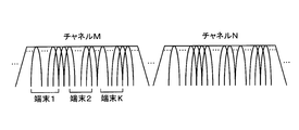
- FIG. 3 shows how a plurality of channels are arranged in the frequency domain.
- a guard band is provided between the channels.
- the bandwidth of one channel is 20 MHz, for example.
- the case where OFDMA communication is performed using a continuous band of one of the channels (here, channel M) corresponds to FIG.
- a plurality of subcarriers orthogonal to each other (for example, 52 in the case of the 20 MHz band) are arranged in a continuous band of the channel M (for example, 20 MHz wide band), and one or a plurality of continuous carriers are arranged based on these subcarriers.
- a resource block whose unit is a subcarrier to be assigned is allocated to terminal 1, terminal 2,...
- the bandwidth (or the number of subcarriers) for each resource block is common to each resource block, but the bandwidth (or the number of subcarriers) may be different for each resource block.
- the number of resource blocks allocated to each terminal is not limited to one resource block per terminal, and a plurality of resource blocks may be allocated to one terminal, and the number of resource blocks allocated to each terminal is different. May be.
- the resource block is composed of a plurality of subcarriers, the arrangement of subcarriers included in the resource block may or may not be continuous. It is also possible to assign a plurality of non-contiguous subcarriers as resource blocks to one terminal.
- At least one subcarrier is arranged as a guard subcarrier between resource blocks allocated to each terminal.
- the number of guard subcarriers arranged between resource blocks may be determined in advance by the system or specification, or may be determined arbitrarily. Moreover, it is not essential to arrange guard subcarriers between resource blocks, and it may be allowed not to arrange guard subcarriers between resource blocks.
- the number of channels used in OFDMA communication is not limited to one, and OFDMA communication can be performed using two or more channels.
- resource blocks may be allocated in each channel independently as described above.
- one terminal may be allowed to receive allocation of a plurality of resource blocks belonging to different channels.
- a continuous frequency region in which a plurality of channels are combined may be defined, and resource blocks may be allocated in the combined frequency region. For example, a 40 MHz frequency region may be defined by combining two 20 MHz wide channels adjacent in frequency, and resource blocks may be allocated based on mutually orthogonal subcarrier groups within the 40 MHz frequency region.
- resource blocks may be allocated based on subcarrier groups orthogonal to each other in each frequency domain.
- a terminal that implements OFDMA has at least a basic channel width of a legacy terminal that is subject to backward compatibility (20 MHz channel width if an IEEE 802.11a / b / g / n / ac standard-compliant terminal is a legacy terminal), It is assumed that a physical packet including a frame can be received and decoded (including decoding and demodulation of an error correction code).
- carrier sense is performed in units of channels.
- the carrier sense includes CCA (Clear Channel Asset) busy / idle physical carrier sense (Physical Carrier Sense) and virtual carrier sense based on the media reservation time described in the received frame (Virtual Carrier Sense). Sense) may be included.
- NAV Network Allocation Vector
- Carrier sense information based on CCA or NAV performed for each channel may be commonly applied to all resource blocks in the channel. For example, resource blocks belonging to a channel whose carrier sense information indicates idle may be processed as being idle by commonly applying the carrier sense information of the channel.
- the terminal according to the present embodiment is not limited to performing carrier sense on a channel basis, and if the terminal implements a mechanism that performs carrier sense on a resource block basis, carrier sense (physical sense on a resource block basis) (Both manual and virtual) may be allowed to be performed.
- OFDMA can be channel-based OFDMA in addition to the resource block-based OFDMA described above.
- the OFDMA in this case is sometimes called MU-MC (Multi-User Multi-Channel).
- MU-MC Multi-User Multi-Channel
- a base station assigns a plurality of channels to a plurality of terminals, and simultaneously uses the plurality of channels to simultaneously transmit to or receive from a plurality of terminals.
- a resource block-based OFDMA is assumed. Base OFDMA embodiments are also feasible.
- a communication method combining OFDMA and MU-MIMO (referred to as OFDMA & MU-MIMO) is also possible.
- OFDMA & MU-MIMO each of a plurality of resource blocks is assigned to a plurality of terminals, and MU-MIMO transmission is performed in resource block units simultaneously in each of the plurality of resource blocks.
- Both uplink OFDMA & MU-MIMO and downlink OFDMA & MU-MIMO are possible.
- OFDMA & MU-MIMO may be used.
- a terminal having the capability of implementing at least one of UL-OFDMA and UL-MU-MIMO may be referred to as a UL-MU terminal.
- a terminal that does not have this capability may be referred to as a legacy terminal.
- a terminal with the enabled capability may be considered as a UL-MU terminal.
- the UL-MU terminal may further include a capability to implement at least one of DL-OFDMA and DL-MU-MIMO.
- a terminal designated as a base station as a target of the current UL-MU communication corresponds to a UL-MU target terminal and is not designated as a target of the current UL-MU as a base station.
- the terminal corresponds to a non-target terminal of UL-MU.
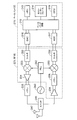
- a wireless communication device mounted on a terminal includes a host processing unit 90, a MAC processing unit 10, a PHY (Physical) processing unit 50, a MAC / A PHY management unit 60, an analog processing unit 70 (analog processing units 1 to N), and an antenna 80 (antennas 1 to N) are included.
- N is an integer of 1 or more.
- a pair of N analog processing units and N antennas are connected, but the present invention is not necessarily limited to this configuration.
- the number of analog processing units may be one, and two or more antennas may be commonly connected to the analog processing unit.
- the MAC processing unit 10, the MAC / PHY management unit 60, and the PHY processing unit 50 correspond to a form of a communication processing device or a baseband integrated circuit that performs processing related to communication with other terminals (including base stations).
- the analog processing unit 70 corresponds to, for example, a form of a wireless communication unit that transmits and receives signals via an antenna 80 or an RF (Radio Frequency) integrated circuit.
- the wireless communication integrated circuit according to the present embodiment may include at least the former of the baseband integrated circuit (communication processing device) and the RF integrated circuit.
- the functions of the communication processing device or the baseband integrated circuit may be performed by software (program) that operates on a processor such as a CPU, may be performed by hardware, or may be performed by both software and hardware. May be.
- the software may be stored in a storage medium such as a ROM or RAM, a hard disk, or an SSD, read by a processor, and executed.
- the memory may be a volatile memory such as a DRAM or a non-volatile memory such as a NAND or MRAM.
- the upper processing unit 90 performs processing for the upper layer on the MAC (Medium Access Control) medium layer.
- the host processing unit 90 can exchange signals with the MAC processing unit 10.
- Typical examples of the upper layer include TCP / IP, UDP / IP, and an upper application layer.
- the upper processing unit 90 may include a buffer for exchanging data between the MAC layer and the upper layer. You may connect with a wired infrastructure via the high-order process part 90.
- the buffer may be a memory, an SSD, a hard disk, or the like. When the buffer is a memory, the memory may be a volatile memory such as a DRAM or a nonvolatile memory such as a NAND or MRAM.
- the MAC processing unit 10 performs processing for the MAC layer. As described above, the MAC processing unit 10 can exchange signals with the host processing unit 90. Further, the MAC processing unit 10 can exchange signals with the PHY processing unit 50.
- the MAC processing unit 10 includes a MAC common processing unit 20, a transmission processing unit 30, and a reception processing unit 40. *
- the MAC common processing unit 20 performs processing common to transmission and reception in the MAC layer.
- the MAC common processing unit 20 is connected to the host processing unit 90, the transmission processing unit 30, the reception processing unit 40, and the MAC / PHY management unit 60, and exchanges signals with each other.
- the transmission processing unit 30 and the reception processing unit 40 are connected to each other.
- the transmission processing unit 30 and the reception processing unit 40 are connected to the MAC common processing unit 20 and the PHY processing unit 50, respectively.
- the transmission processing unit 30 performs transmission processing at the MAC layer.
- the reception processing unit 40 performs reception processing at the MAC layer.
- the PHY processing unit 50 performs processing for the physical layer (PHY layer). As described above, the PHY processing unit 50 can exchange signals with the MAC processing unit 10.
- the PHY processing unit 50 is connected to the antenna 80 via the analog processing unit 70.
- the MAC / PHY management unit 60 is connected to the host processing unit 90, the MAC processing unit 10 (more specifically, the MAC common processing unit 20), and the PHY processing unit 50.
- the MAC / PHY management unit 60 manages the MAC operation and the PHY operation in the wireless communication apparatus.
- the analog processing unit 70 includes an analog / digital and digital / analog (AD / DA) converter and an RF (Radio Frequency) circuit, converts the digital signal from the PHY processing unit 50 into an analog signal having a desired frequency, and an antenna. A high-frequency analog signal transmitted from the antenna 80 and received from the antenna 80 is converted into a digital signal.
- AD / DA conversion is performed by the analog processing unit 70, but a configuration in which the PHY processing unit 50 is provided with an AD / DA conversion function is also possible.
- the wireless communication apparatus includes (integrates) the antenna 80 as a constituent element in one chip, so that the mounting area of the antenna 80 can be reduced. Further, in the wireless communication apparatus according to the present embodiment, as illustrated in FIG. 1, the transmission processing unit 30 and the reception processing unit 40 share N antennas 80. Since the transmission processing unit 30 and the reception processing unit 40 share the N antennas 80, the wireless communication apparatus in FIG. 1 can be reduced in size. Of course, the wireless communication apparatus according to the present embodiment may have a configuration different from that illustrated in FIG.
- the analog processing unit 70 converts the analog signal received by the antenna 80 into a baseband signal that can be processed by the PHY processing unit 50, and further converts it into a digital signal.
- the PHY processing unit 50 receives a digital reception signal from the analog processing unit 70 and detects the reception level. The detected reception level is compared with the carrier sense level (threshold value). If the reception level is equal to or higher than the carrier sense level, the PHY processing unit 50 indicates that the medium (CCA: Clear Channel Assessment) is busy. Are output to the MAC processing unit 10 (more precisely, the reception processing unit 40). If the reception level is less than the carrier sense level, the PHY processing unit 50 outputs a signal indicating that the medium (CCA) is idle to the MAC processing unit 10 (more precisely, the reception processing unit 40). .
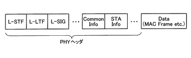
- the PHY processing unit 50 performs a decoding process (including decoding and demodulation of an error correction code) on the received signal, a process of removing a physical header including a preamble (PHY header), and the like to extract a payload.
- this payload is converted to PSDU (physical layer convergence procedure) on the PHY side. (PLCP) service data unit).
- PSDU physical layer convergence procedure
- the PHY processing unit 50 passes the extracted payload to the reception processing unit 40, and the reception processing unit 40 handles this as a MAC frame.
- this MAC frame is converted into MPDU (medium access control (MAC) protocol data). unit).
- MPDU medium access control
- the PHY processing unit 50 notifies the reception processing unit 40 when reception of the reception signal is started, and notifies the reception processing unit 40 when reception of the reception signal is completed.
- the received signal can be normally decoded as a physical packet (PHY packet) (if no error is detected)
- the PHY processing unit 50 notifies the reception end of the received signal and the medium is idle. Is sent to the reception processing unit 40.
- the PHY processing unit 50 notifies the reception processing unit 40 that an error has been detected with an appropriate error code corresponding to the error type.
- the PHY processing unit 50 determines that the medium has become idle, the PHY processing unit 50 notifies the reception processing unit 40 of a signal indicating that the medium is idle.
- the MAC common processing unit 20 mediates transmission of transmission data from the upper processing unit 90 to the transmission processing unit 30 and transmission of received data from the reception processing unit 40 to the upper processing unit 90, respectively.
- data in this MAC data frame is called MSDU (medium access control (MAC) service data unit).
- MSDU medium access control
- the MAC common processing unit 20 once receives an instruction from the MAC / PHY management unit 60, converts the instruction into a suitable one for the transmission processing unit 30 and the reception processing unit 40, and outputs them.
- the MAC / PHY management unit 60 corresponds to, for example, SME (Station Management Entity) in the IEEE 802.11 standard.
- SME Stim Management Entity
- the interface between the MAC / PHY management unit 60 and the MAC common processing unit 20 corresponds to MLME SAP (MAC subLayer Managment Access Point) in the IEEE 802.11 standard
- MLME SAP MAC subLayer Managment Access Point
- An interface with the processing unit 50 corresponds to a PLME SAP (Physical Layer Management Service Access Point) in an IEEE 802.11 wireless LAN (Local Area Network).
- the MAC / PHY management unit 60 is depicted as if the function unit for MAC management and the function unit for PHY management are integrated, but may be separately implemented. Good.
- the MAC / PHY management unit 60 holds a management information base (MIB).
- the MIB holds various information such as whether the capability and various functions of the terminal itself are valid or invalid. For example, whether or not the own terminal is a UL-MU compatible terminal, and in the case of a UL-MU compatible terminal, ON / OFF information of the function of the ability to implement UL-MU may be held.
- the memory for holding and managing the MIB may be included in the MAC / PHY management unit 60, or may be provided separately without being included in the MAC / PHY management unit 60.
- the MAC / PHY management unit 60 can refer to the other memory and rewrites rewritable parameters in the memory. It can be performed.
- the memory may be a volatile memory such as a DRAM or a non-volatile memory such as a NAND or MRAM. Further, not a memory but a storage device such as an SSD or a hard disk may be used.
- these pieces of information of other terminals as non-base stations can also be acquired by notification from the terminals. In that case, the MAC / PHY management unit 60 can refer to and rewrite information on other terminals.
- the MAC / PHY management unit 60 or the MAC common processing unit 20 can refer to / rewrite the other memory.
- the base station MAC / PHY management unit 60 assigns a terminal to which a resource block for UL-MU communication is simultaneously allocated based on various information related to a terminal as a non-base station or a request from the terminal when transmitting UL-MU.
- a grouping function for selecting (that is, selecting a terminal as a target of the current UL-MU) may be provided.
- the MAC / PHY management unit 60 or the MAC processing unit 10 may manage the transmission rate applied to the MAC frame to be transmitted and the physical header.
- the MAC / PHY management unit 60 of the base station may define a support rate set that is a rate set supported by the base station.
- the support rate set may include a rate required to be supported by a terminal connected to the local station and an optional rate.
- the MAC processing unit 10 handles three types of MAC frames, a data frame, a control frame, and a management frame, and performs various processes defined in the MAC layer.
- three types of MAC frames will be described.
- the management frame is used for management of communication links with other terminals.
- the management frame for example, there is a beacon frame that broadcasts group attributes and synchronization information in order to form a wireless communication group that is a Basic Service Set (BSS) in the IEEE 802.11 standard.
- BSS Basic Service Set
- a state where a certain terminal has exchanged information necessary for performing wireless communication with another terminal is expressed as a communication link established.
- Necessary information exchange includes, for example, notification of functions supported by the terminal (for example, support for UL-MU system, various capabilities described later, etc.) and negotiation for setting of the system.
- the management frame is generated based on an instruction received by the transmission processing unit 30 from the MAC / PHY management unit 60 via the MAC common processing unit 20.
- the transmission processing unit 30 has notification means for notifying other terminals of various information via the management frame.
- the notification means of the terminal as a non-base station transmits information indicating whether it is compatible with a UL-MU compatible terminal, an IEEE 802.11n compatible terminal, or an IEEE 802.11ac compatible terminal in a management frame.
- the station may be notified of the type of its own terminal.
- this management frame for example, there is an Association Request frame used in an association process, which is one of procedures for a terminal to authenticate with a base station, or a Reassociation Request frame used in a rear association process.
- the notification means of the base station may notify the non-base station terminal of information on availability of support for UL-MU communication via a management frame.
- Examples of the management frame used for this include a Beacon frame and a Probe Response frame that is a response to a Probe Request frame transmitted by a non-base station terminal.
- the base station may have a function of grouping terminal groups connected to its own device.
- the above notification means of the base station may notify the group ID of each group assigned to each terminal via a management frame.
- this management frame for example, there is a Group ID Management frame.
- the group ID may be, for example, a group ID defined in IEEE Std 802.11ac-2013.
- the base station may notify information necessary for identifying a resource block used by a terminal belonging to the group via an arbitrary management frame. Good.
- the reception processing unit 40 has receiving means for receiving various information from other terminals via management frames.
- the receiving unit of the base station may receive information on whether to support UL-MU communication from a terminal as a non-base station. Further, information on a channel width (maximum usable channel width) that can be handled when the terminal is a legacy terminal (such as a terminal that supports the IEEE 802.11a / b / g / n / ac standard) may be received.
- the receiving means of the terminal may receive information on availability of UL-MU communication from the base station.
- a UL-MU compatible terminal uses a resource block or channel that it desires to use for UL-MU transmission, or both, a channel that is non-interfering with carrier sense, or a resource block that is non-interfering, Or you may select from both of these. Then, information regarding the selected resource block and / or channel may be notified to the base station. In this case, the base station may perform resource block allocation for UL-MU communication to each UL-MU compatible terminal based on the information.
- the channels used in the UL-MU communication may be all channels that can be used as a wireless communication system, or some (one or more) channels.
- the data frame is used to transmit data to the other terminal in a state where a communication link is established with the other terminal.
- data is generated in the terminal by a user's application operation, and the data is carried by a data frame.
- the generated data is passed from the upper processing unit 90 to the transmission processing unit 30 via the MAC common processing unit 20, and the transmission processing unit 30 puts the data in the frame body field and adds a MAC header.
- a data frame is generated.
- the PHY processing unit 50 adds a physical header to the data frame to generate a physical packet, and the physical packet is transmitted via the analog processing unit 70 and the antenna 80.
- the physical layer is processed based on the physical header to extract a MAC frame (in this case, a data frame), and the data frame is passed to the reception processing unit 40.
- the reception processing unit 40 extracts the information of the frame body field as data, and the extracted data is passed through the MAC common processing unit 20. To the host processor 90. As a result, application operations such as data writing and reproduction occur.
- the control frame is used for control when the management frame and the data frame are transmitted / received (exchanged) to / from another wireless communication apparatus.
- As the control frame for example, before starting the exchange of the management frame and the data frame, an RTS (Request to Send) frame exchanged with another wireless communication device in order to reserve a wireless medium, a CTS (Clear to) Send) frame.
- As another control frame there is a delivery confirmation response frame for confirming delivery of the received management frame and data frame. Examples of the delivery confirmation response frame include an ACK (Acknowledgement) frame and a BA (BlockACK) frame. Since the CTS frame is also transmitted as a response to the RTS frame, it can be said that the CTS frame represents a delivery confirmation response.
- the CF-End frame is also one of the control frames.
- the CF-End frame is a frame that announces the end of CFP (Contents Free Period), that is, a frame that permits access to the wireless medium.
- These control frames are generated by the transmission processing unit 30.
- the reception processing unit 40 determines whether the response frame (control frame) needs to be transmitted and generates a frame.
- Necessary information (control frame type, information set in the RA field, etc.) is output to the transmission processing unit 30 together with a transmission instruction.
- the transmission processing unit 30 generates an appropriate control frame based on information necessary for generating the frame and a transmission instruction.
- the MAC processing unit 10 needs to acquire an access right (transmission right) on a wireless medium when transmitting a MAC frame based on CSMA / CA (Carrier Sense Multiple Access With Carrier Avidance).
- the transmission processing unit 30 measures transmission timing based on the carrier sense information from the reception processing unit 40.
- the transmission processing unit 30 gives a transmission instruction to the PHY processing unit 50 according to the transmission timing, and passes the MAC frame.
- the transmission processing unit 30 may instruct the modulation scheme and the encoding scheme used for transmission together. In addition to these, the transmission processing unit 30 may instruct transmission power.
- the MAC processing unit 10 After obtaining the access right (transmission right), the MAC processing unit 10 is able to occupy the medium (Transmission Opportunity; TXOP), and other wireless communication is performed, although there are restrictions on QoS (Quality of Service) attributes and the like.
- MAC frames can be exchanged continuously with the device.
- TXOP for example, a wireless communication apparatus transmits a predetermined frame (for example, an RTS frame) based on CSMA / CA (Carrier Sense Multiple Access with Carrier Avoidance), and a response frame (for example, a CTS frame) is correctly transmitted from another wireless communication apparatus. Earned when received.
- the other wireless communication device transmits the response frame after a minimum frame interval (short interframe space; SIFS).
- SIFS short interframe space
- a data frame that directly requests transmission of a delivery confirmation response frame by unicast (a frame having a shape in which frames are concatenated as described later, or a payload is concatenated).
- a management frame may be transmitted, and a delivery acknowledgment response frame (ACK frame or BlockACK frame) may be received correctly.
- Duration field a Duration / ID field of the frame. May be interpreted as having acquired a TXOP for the period described in the Duration field from the stage of transmitting the frame.
- the reception processing unit 40 manages the carrier sense information described above.
- the carrier sense information is managed for each channel, for example.
- This carrier sense information is based on the physical carrier sense information regarding busy / idle of the medium (CCA) input from the PHY processing unit 50 and the medium reservation time described in the received frame. Includes both virtual carrier sense information. If any one of the carrier sense information indicates busy, the medium is considered busy and transmission is prohibited during that time.
- the medium reservation time is described in the Duration field in the MAC header.
- NAV Network Allocation Vector
- the data frame may be configured to connect a plurality of MAC frames or payload portions of a plurality of MAC frames.
- the former is called A (Aggregated) -MPDU in the IEEE 802.11 standard, and the latter is called A (Aggregated) -MSDU (MAC service data unit).
- A-MPDU a plurality of MPDUs are connected in PSDU.
- management frames and control frames are also subject to concatenation.
- a plurality of data payloads MSDU are connected in a frame body of one MPDU.
- delimiter information (length information, etc.) is stored in the data frame so that the concatenation of multiple MPDUs and the concatenation of multiple MSDUs can be properly separated at the receiving terminal.
- a combination of both A-MPDU and A-MSDU may be used.
- the A-MPDU may target only one MAC frame instead of a plurality of MAC frames, and in this case, the delimiter information is stored in the data frame.
- the data frame is an A-MPDU or the like, responses for a plurality of MAC frames are transmitted together.
- a BA (BlockACK) frame is used instead of an ACK frame.
- MPDU notation may be used, but this includes not only a single MAC frame but also the above-described A-MPDU or A-MSDU.
- a non-base station terminal joins a BSS (this is called an infrastructure BSS) formed mainly by a base station, and data frames can be exchanged within the BSS.
- a plurality of procedures are defined in stages. For example, there is a procedure called association, and a non-base station terminal transmits an association request frame to a base station to which the terminal requests connection.
- the base station transmits an ACK frame for the association request frame, and then transmits an association response frame that is a response to the association request frame.
- the terminal stores the capability of its own terminal in the association request frame, and can notify the base station of the capability of its own terminal by transmitting it.
- a terminal transmits a channel or resource (resource block or stream) that can be supported by the terminal in the association request frame, or both of them, and information for specifying a standard that the terminal supports. Also good.
- This information may also be included in a frame that is transmitted in a procedure called reassociation for reconnection to another base station.
- a reassociation request (Reassociation Request) frame is transmitted from the terminal to another base station that requests reconnection.
- the other base station transmits an ACK frame for the reassociation request frame, and then transmits a reassociation response frame that is a response to the reassociation request frame.
- a beacon frame in addition to the association request frame and the reassociation request frame, a beacon frame, a probe response frame, or the like may be used.
- the beacon frame is basically transmitted by the base station, and can store a parameter indicating the BSS attribute and a parameter notifying the base station itself. Therefore, the base station may add information indicating whether or not the base station can cope with UL-MU communication as a parameter for reporting the capability of the base station itself. Moreover, you may notify the information of the support rate (Supported Rate) of a base station as another parameter.
- the support rate may include a mandatory rate and an optional rate.
- the base station transmits the capability (UL- Notification of support for MU communication, support rate, etc.).
- the terminal can also enable the UL-MU communication function of its own terminal, for example.
- the terminal may notify information on a rate that can be executed by the terminal among the support rates of the base station as information to notify the base station of the capability of the terminal.
- an indispensable rate among the support rates it is assumed that a terminal connected to the base station has an ability to execute the indispensable rate.
- the notification can be omitted if there is information that is indispensable by notifying other information among the information handled above. For example, if a capability corresponding to a new standard or specification is defined, and if it corresponds to it, it is a terminal supporting UL-MU itself, then notification that it is an IFDMA compatible terminal must be explicitly not performed. Also good.
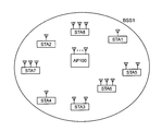
- FIG. 4 shows a wireless communication system according to the present embodiment.
- This system includes a base station (AP: Access Point) 100 and a plurality of terminals (STA: STATION) 1-8.
- the base station 100 and the terminals 1 to 8 under its control form a BSS (Basic Service Set) 1.
- BSS Basic Service Set
- This system is a wireless LAN system conforming to the IEEE 802.11 standard using CSMA / CA (Carrier Sense Multiple Access with Carrier Avidance).
- legacy terminals such as IEEE802.11a / b / g / n / ac standard compatible terminals
- UL-MU terminal may exist in the BSS1.
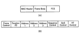
- FIG. 5A shows a basic format example of the MAC frame.
- the data frame, management frame, and control frame basically have such a frame format.
- This frame format includes fields of a MAC header (MAC header), a frame body (Frame body), and an FCS.
- the MAC header includes Frame Control, Duration / ID (sometimes referred to simply as Duration), Address1, Address2, Address3, Sequence Control, QoS Control, and HT (High Thr). Contains fields.
- an Address4 field may further exist.
- a notification field (or may be called a control field) may exist as a field or a subfield in the MAC header.
- the Address 1 field contains the recipient address (Receiver Address; RA), the Address 2 field contains the source address (Transmiter Address; TA), and the Address 3 field contains the BSS identifier according to the frame usage.
- BSSID Basic Service Set IDentifier
- Frame Control field two fields of type (Type) and subtype (Subtype) are set as described above.
- Data frames, management frames, and control frames are roughly classified in the Type field, and detailed classification among the roughly classified frames, for example, identification of BA frames, BAR frames, and Beacon frames in management frames is performed. This is done in the Subtype field.
- the Duration / ID field describes the medium reservation time.
- the medium is virtually transmitted from the end of the physical packet including the MAC frame to the medium reservation time. Is determined to be busy.
- the mechanism for determining that the medium is virtually busy, or the period during which the medium is virtually busy is called NAV (Network Allocation Vector) as described above.
- the QoS field is used for performing QoS control in which transmission is performed in consideration of frame priority.
- the HT Control field is a field introduced by IEEE802.11n, and exists when the order field is set to 1 in a QoS data frame or a management frame.
- the HT Control field can be extended to the IEEE 802.11ac VHT (Very High Throughput) Control field, the next generation wireless LAN standard IEEE 802.11ax HE (High Efficiency) Control field E, and each E Notification according to various functions of IEEE802.11ac or IEEE802.11ax can be made.
- IEEE 802.11ac VHT Very High Throughput
- IEEE 802.11ax HE High Efficiency Control field E
- an information element (Information element; IE) assigned with a unique Element ID (IDentifier) is set in the Frame Body field.
- IE Information element
- IDentifier a unique Element ID
- the information element includes an Element ID field, a Length field, and an Information field.
- the information element is identified by an Element ID.
- the information field stores the content of information to be notified, and the Length field stores length information of the information field.
- a notification field (control field) described later may be set in the body field of the management frame. In this case, the notification field may have the form of an information element.
- FCS Full Check Sequence
- CRC Cyclic Redundancy Code
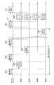
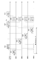
- FIG. 7 shows an example of an operation sequence between the base station (AP) 101 according to the present embodiment and a plurality of terminals including the terminal (STA) 1 to the terminal (STA) 4.
- a plurality of terminals including the terminals 1 to 4 are UL-MU compatible terminals.
- terminals other than the terminals 1 to 4 are not shown, but actually, other terminals 5 to 8 may exist as shown in FIG.
- a short section indicated by a solid line with a double-pointed arrow represents a short interframe space (SIFS).
- SIFS short interframe space
- the section to which reference sign T1 is attached represents SIFS or other fixed time (IFS).
- Sections 501A, 503A, and 505A indicated by bold arrows represent the sum of the DIFS / AIFS [AC] time and the CSMA / CA backoff (BackOff) time (carrier sense time or standby time).
- the SIFS and DIFS / AIFS [AC] time is an example, and another time (IFS) may be used as long as it is a predetermined time.
- the DIFS / AIFS [AC] time means the time of either DIFS or AIFS [AC]. When it is not compatible with QoS, it indicates DIFS time, and when it is compatible with QoS, it indicates AIFS [AC] time determined according to an access category (AC) (to be described later) of data to be transmitted.
- communication is performed individually with a basic channel width (or a combined bandwidth of a plurality of channels) between the base station and individual terminals including the terminals 1 to 4.
- the base station determines the start of UL-MU (UL-OFDMA or UL-MIMO) transmission.
- the base station decides to start UL-MU transmission, it transmits a trigger frame (more specifically, a physical packet including the trigger frame) 507 that triggers UL-MU transmission, and terminals 1 to 4 receive the trigger frame.
- Data frames (more specifically, physical packets including data frames) 509, 510, 511, and 512 are transmitted after a certain time T1. Thereby, UL-MU transmission from the terminals 1 to 4 to the base station is performed.
- the terminal 1 transmits a data frame (more specifically, a physical packet including a data frame) 501 including data to be transmitted, and when the base station normally receives the data frame 501, the SIFS time from the completion of reception of the data frame 501 Later, an ACK frame (more specifically, a physical packet including an ACK frame) 502 which is a delivery confirmation response frame is returned.
- the terminal 1 receives the ACK frame 502 and determines that the data frame 501 has been successfully transmitted.
- the data frame to be transmitted to the base station may be an aggregation frame (A-MPDU or the like), and the delivery confirmation response frame to which the base station responds may be a BA frame (the same applies hereinafter).
- the terminal 2 acquires the access right and transmits the data frame 503, and the base station transmits the ACK frame 504 after SIFS time from the completion of reception of the data frame 503.
- the terminal 3 obtains the access right and transmits the data frame 505, and the base station transmits the ACK frame 506 after SIFS time from completion of reception of the data frame 505.
- the example in the figure shows an example in which only the terminals 1 to 3 transmit data frames to the base station, but the terminal 4 and the terminals 5 to 8 (not shown) may exchange frames in the same manner.
- the communication is performed in the order of the terminal 1, the terminal 2, and the terminal 3. However, this is only the order in which the access right is acquired, and the communication may be performed in any order.
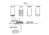
- each terminal transmits notification information (or may be referred to as control information) that is information necessary for the UL-MU to the notification field (control information). Field). That is, the data frame has a role of transmitting notification information necessary for the UL-MU in addition to the role of transmitting the data to the base station.
- the data frame includes information (the above data) for a purpose different from the notification information in the frame body field.
- the notification information can be set not only in a data frame transmitted by a single user but also in a data frame transmitted by UL-MU.
- Examples of the notification information include information on the presence / absence of a UL-MU transmission request, information on the presence / absence of data desiring UL-MU transmission, and information on the data type of data desiring UL-MU transmission.
- information such as the number and / or size of data regarding the data amount of data desired to be transmitted by UL-MU.
- there is a desired communication method either OFDMA or MU-MIMO communication method.
- the desired resource resource block in OFDMA, stream in MU-MIMO
- the desired resource may be specified by a resource number or a stream number, or may be specified by other methods.
- the notification information may include at least one of information in the example described here, or may include information of a type not described here.
- the notification information is spontaneously transmitted from each terminal in a state in which no notification information transmission request is made from the base station. That is, the notification information is transmitted in the form of sharing the frame transmitted by each terminal with the normal single user communication.
- the notification field for setting the notification information may be provided as a new field in the MAC header as shown in FIG.
- a reserved area in an existing field (a field defined by an existing standard) may be used as a notification field.
- the notification field may be provided in the physical header, or a reserved area in an existing field in the physical header may be used as the notification field.
- the notification field may be set not in the MAC header but in the body field of the frame. For example, when the data frame transmitted to the base station is an A-MPDU, one of a plurality of MAC frames stored in the payload of the data frame may be used as a management frame, and the frame body field of the management frame may be used as a notification field. .
- the notification field may have the information element format as previously shown in FIG. 6, and a new element ID may be assigned to the information element that sets the notification field. . Also, a new value may be defined for the frame including the notification field as a subtype of the Frame Control field.
- the information element of the notification field may be additionally set in the frame body of the existing management frame. The specific format of the notification field depends on the content of notification information to be set.
- the notification information notified by each terminal in the notification field will be described.
- the notification information is used by the base station for scheduling including determination of necessary items of UL-MU.
- notification information there is information on whether or not there is a request for UL-MU transmission. If the remaining data to be transmitted to the base station exists in the transmission buffer (transmission queue), it can be said that there is a request for UL-MU transmission.
- 1 bit may be used. When bit 1 is set, a UL-MU transmission request may be issued. When bit 0 is set, there may be no UL-MU transmission request. Alternatively, the bit relationship may be reversed.
- the base station when selecting a UL-MU transmission target terminal, the base station may select a terminal having a UL-MU transmission request.
- the more data field used for notifying the terminal in the power save mode of the presence / absence of the remaining data for downlink may be used as the notification information of the first example.
- the presence of data for transmission may be notified by setting the bit of the more data field to 1.
- a method of not providing a notification field is also possible.
- the terminal has data to be transmitted to the base station, there may be a situation where it is desired to transmit by single user transmission without transmitting by UL-MU transmission.
- UL-MU transmission a resource (for example, one channel bandwidth) is shared by a plurality of terminals, so that the frame length (physical) when sending the same data size is compared with single user transmission in which one terminal can use one channel bandwidth. (Packet length) becomes longer.
- Packet length As the frame length increases, the possibility of transmission failure (for example, the possibility of detecting a frame error on the receiving side) increases accordingly.
- the terminal wants to transmit reliably, there may be a situation where the user does not want to perform the UL-MU transmission but performs the single user transmission. In such a case, the terminal sets information indicating that there is no request for transmission (there is no remaining data) in the notification field, and the data can be transmitted as a single user on a CSMA / CA basis as usual. Good.
- the notification information information for specifying the presence or absence of a UL-MU transmission request for each data type in the terminal (that is, the presence or absence of data for UL-MU transmission for each data type) may be used.
- the data type may be IEEE 802.11 standard TID (Traffic ID) or AC (Access Category). The following description will be based on AC as the data type, but TID may be used instead (the same applies to the description of the third and subsequent examples of notification information).
- EDCA Enhanced Distributed Channel Access
- A access category
- EDCA Enhanced Distributed Channel Access
- the wireless LAN of the IEEE 802.11 standard when data is transferred from an upper layer (LLC layer or the like) to the MAC layer, if the terminal supports QoS (Quality of Service), the traffic type (TID) is set together with the data. Be notified.
- QoS Quality of Service
- TID traffic type
- IEEE 802.11n and IEEE 802.11ac compatible terminals support QoS.
- the data is classified into four ACs based on the traffic type, for example.
- TID values 0 to 15 exist, 0 to 7 are used in terminals (including base stations) in an EDCA environment, and 8 to 15 are HCCA (hybrid coordination function (HCF) controlled channel access (HCCA)) environment or a terminal in an HEMM (HCCA, EDCA mixed mode) environment (including base stations).
- HCF hybrid coordination function
- HCCA hybrid coordination function
- HCCA hybrid coordination function controlled channel access
- HEMM HEMM
- EDCA mixed mode including base stations
- a transmission buffer (transmission queue) is provided for each of the four ACs, and the classified data is stored in the corresponding transmission buffer.
- the transmission buffer may be a memory, an SSD, a hard disk, or the like.
- the transmission buffer is a memory
- the memory may be a volatile memory such as a DRAM or a nonvolatile memory such as a NAND or MRAM.
- EDCA parameter is defined for each AC, and the difference in the priority of medium access at the time of transmission is determined by this parameter.
- parameters include AIFS [AC], and a minimum value CWmin and a maximum value CWmax of a contention window (Content Window: CW).
- AIFS [AC], CWmin, and CWmax are set to smaller values as the medium access priority is higher.
- TXOP limit is the upper limit value of TXOP.
- the procedure for data transmission based on CSMA / CA is performed independently for each AC having data for transmission. That is, for each AC, carrier sense is performed during the standby time including AIFS [AC] and the back-off time, and the AC whose standby time becomes zero first acquires the access right. If there are a plurality of ACs whose standby times simultaneously become zero, an AC with a high medium access priority obtains an access right.
- the back-off time (random time) is obtained by multiplying an integer randomly selected from the contention window (Content Window: CW) by the slot time.
- the initial value of CW is given by CWmin, and every time retransmission is performed, the value of CW is increased until it reaches CWmax.
- FIG. 9 shows an example of a format indicating the presence / absence of a UL-MU transmission request for each AC (presence / absence of data for UL-MU transmission).
- One bit is provided for each of BACKGROUND (AC_BK), BEST EFFORT (AC_BE), VIDEO (AC_VI), and VOICE (AC_VO).
- Bit 1 can be set when data exists in the transmission queue corresponding to each of these ACs, and 0 can be set when there is no data. Alternatively, the bit relationship may be reversed. In this example, four bits are required to indicate the presence / absence of data for transmission of each AC.
- FIG. 10 shows a specific operation example for notifying the presence / absence of data for transmission of each AC using the format of FIG.
- a transmission queue is provided for each AC, and there is one MSDU (may be MPDU, PSDU, or PPDU) in the transmission queue of AC_VO.
- Two MSDUs exist in the AC_VI transmission queue, no MSDU exists in the AC_BK transmission queue, and one MSDU exists in the AC_BE transmission queue.
- the size of each MSDU does not need to be the same, and the size of the MSDU is different between ACs in the illustrated example. Assume that the procedure according to CSMA / CA is started independently for each AC at the time of transmission, and AC_VO first reaches the waiting time of zero and acquires the access right.
- the MSDU at the head of the AC_VO transmission queue is read, and the transmission queue becomes empty.
- a body field of the MAC frame is generated based on the read MSDU, and a MAC frame is generated by adding a MAC header to the body field.
- information indicating the presence / absence of remaining data for transmission is set for each AC in the notification field of the MAC header. Since the transmission queue of AC_VO is empty, bit 0 is present, and MSDU is present in the transmission queue of AC_VI (two). Therefore, bit 1 is present because the transmission queue of AC_BK is empty. Therefore, bit 1 is set in the corresponding subfield.
- the generated MAC frame is transmitted to the base station in a TXOP based on the acquired access right.
- the terminal 1 receives a delivery confirmation response frame (such as a BA frame or an ACK frame) from the base station after SIFS time from the transmission of the MAC frame.
- a transmission priority (distinguishable from the medium access priority described above) may be set for each AC. For example, the priority of “high”, “medium”, and “lower” may be set for each AC. Less or more than three priorities may be defined. If there is no data for transmission, the transmission priority may be set to “down”, or a priority such as “none” indicating that there is no data for transmission may be defined separately. Good.
- the third example may be combined with the second example to define notification information. In this case, the presence / absence of data for transmission and the priority of transmission are set for each AC.
- an AC that is most desired to transmit data that is, an AC that has the highest transmission priority may be specified.
- 2 bits are required to specify one of these four ACs.
- “00” may be specified for AC-VO, “01” for AC-VI, “11” for AC-BK, and “10” for AC-BE.
- the fourth example may be combined with the second example to define the notification information.
- a bit indicating the presence / absence of data transmission for example, 4 bits
- a bit (for example, 2 bits) designating one AC in this example are required.
- the amount of data may be the number of data (in this case, MSDU, but may be PPDU, or other PDU or SDU) existing in the transmission queue for each AC, the size of each MSDU, or both of them. .
- the total data size of the MSDU remaining in the transmission queue may be used.
- not the size but the time length may be used. Any information other than those described here may be used as long as the data amount can be specified. For example, when transmission is performed by transmission of an aggregation frame (A-MPDU, A-MSDU, or the like), information on how many aggregation frames exist may be used.
- the quantization method used when expressing the data amount may be any method.
- the basic unit may be 32 ⁇ s, which is a time length, and the data amount may be represented by an integer multiple of 32 ⁇ s.
- the field length for setting the data amount is 8 bits, for example, 32 ⁇ s to 8160 ⁇ s can be expressed.
- 32 ⁇ s is an example, and other lengths of time may be used as the basic unit.
- 8 bits is an example, and other field lengths may be used.
- the basic unit may be 4096 octets as the size, and the data amount may be expressed by an integer multiple of 4096 octets.
- the field length for setting the data amount is 4 bits and the field value is 1, it represents 4096 octets, and when it is 2, 8192 octets are represented. If the actual data amount does not match an integer multiple of 4096 octets, the closest value may be adopted that is larger than the actual data amount. A field value of 15 may indicate that the amount of data is greater than 57344 octets. Note that 4096 octets are an example, and other sizes may be used as the basic unit. Also, 4 bits is an example, and other field lengths may be used.
- information for specifying the amount of data for transmission (not by AC) in the terminal may be used.
- the number of transmission data in this case, MSDU, but may be PPDU, other PDU or SDU
- the size of each MSDU or these Both are good.
- the total size of MSDUs remaining for transmission may be used, or information other than that described here may be used.
- not the size but the time length may be used. Any information other than those described here may be used as long as the data amount can be specified. For example, when transmission is performed by transmission of an aggregation frame (A-MPDU, A-MSDU, or the like), information on how many aggregation frames exist may be used.
- A-MPDU aggregation frame
- A-MSDU aggregation frame
- the quantization method used when expressing the data amount may be any method.
- the basic unit may be 32 ⁇ s, which is a time length, and the data amount may be represented by an integer multiple of 32 ⁇ s.
- the field length for setting the data amount is 8 bits, for example, 32 ⁇ s to 8160 ⁇ s can be expressed.
- 32 ⁇ s is an example, and other lengths of time may be used as the basic unit.
- 8 bits is an example, and other field lengths may be used.
- the basic unit may be 4096 octets as the size, and the data amount may be expressed by an integer multiple of 4096 octets.
- the field length for setting the data amount is 4 bits and the field value is 1, it represents 4096 octets, and when it is 2, 8192 octets are represented. If the actual data amount does not match an integer multiple of 4096 octets, the closest value may be adopted that is larger than the actual data amount. A field value of 15 may indicate that the amount of data is greater than 57344 octets. Note that 4096 octets are an example, and other sizes may be used as the basic unit. Also, 4 bits is an example, and other field lengths may be used.
- information for specifying the TXOP length necessary for the next transmission may be used for all or part of ACs.
- the TXOP length may be represented by an integral multiple of 32 ⁇ s, for example, where the basic unit is 32 ⁇ s.
- the field length for setting the TXOP length is 8 bits, for example, 32 ⁇ s to 8160 ⁇ s can be expressed. Note that 32 ⁇ s is an example, and other lengths of time may be used as the basic unit. Also, 8 bits is an example, and other field lengths may be used.
- the data amount required for the next transmission may be used for all or a part of the AC.
- the data amount may be a data length such as PPDU or MSDU.
- the method of expressing the data amount is the same as the notification information in the fifth or sixth example.
- the information for specifying the TXOP length or the data amount necessary for the next transmission is shown for each AC.
- the information for specifying the TXOP length or the data amount necessary for the next transmission in the terminal is not shown for each AC. It may be information.
- the notification information it may be information on whether the terminal desires OFDMA or MU-MIMO (which may be MU-MIMO & OFDMA as described above, and so on). If the terminal is compatible with only one of the communication methods and the base station has been notified of the communication method that the terminal can support at the time of the association process or the like, the notification of this information may be omitted.
- information indicating the desired resource (resource block in OFDMA, stream in MU-MIMO) or the number of resources is indicated according to the UL-MU communication scheme (OFDMA or MU-MIMO). It may be information or both.
- the desired resource may be specified by the resource number or the stream number, or by another method.
- a desired resource may be specified by specifying a range of resource numbers. For example, when there are resource numbers 1 to 8, a range such as “resource numbers 6 to 8” may be designated. At this time, a plurality of ranges may be designated.
- the various types of notification information shown in the first to ninth examples described above are used independently, and may be used in any combination as long as there is no contradiction.
- the notification information may be defined by combining both the first example and the second example. Three or more pieces of notification information may be combined.
- the first to ninth examples are examples, and information other than these can be used as the notification information.
- information representing a data generation cycle in the terminal may be used.
- the generation cycle may be the above-described information for each AC or TID.
- the information which represents the value of the communication delay (allowable delay) permitted by the application in a terminal may be sufficient.
- TSPEC Traffic Specification
- MSDU length for example, average data rate, MSDU length, minimum physical rate, etc.
- minimum physical rate for example, average data rate, MSDU length, minimum physical rate, etc.
- some or all of the notification information may be set using an existing field such as a QoS Control field.
- a reserved area in an existing field may be used.
- the existing field has a plurality of pattern formats, a new pattern for setting notification information is newly defined, and a new pattern format is set.
- Notification information may be set in.
- existing field values themselves as notification information.
- the format of the QoS Control field differs depending on the subtype of the Frame Control field, but includes a TID subfield and a TXOP Duration Requested subfield as an example.
- the TID subfield the TID of the currently transmitted data is set, and in the TXOP Duration Requested subfield, a value necessary for the next TXOP is set.
- the values of these subfields may be used as notification information.
- the base station stores the notification information notified from each terminal in the notification field in an internal storage device, and manages the notification information for each terminal, thereby managing the state for each terminal.
- notification of notification information in the notification field includes a case where an existing field is used.
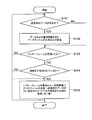
- the base station determines to perform UL-MU transmission at an arbitrary timing, a predetermined timing, or a timing when a predetermined condition is satisfied.
- the predetermined timing may be a certain beacon interval period or other timing.
- As a predetermined condition there may be a certain number or more of terminals having hope of UL-MU transmission, and radio wave conditions (busy rate, usage rate, or other indicators) satisfy a predetermined standard. You may require that.
- the base station may determine to perform UL-MU transmission independently of reception of data frames transmitted from the terminals 1 to 4 as a single user.
- a target terminal for UL-MU transmission is selected.
- selection may be made from a terminal having a request for UL-MU transmission.
- the terminal may be selected from terminals having transmission data of a specific data type (such as AC or TID).
- the target terminal may be selected based on the data amount or the TXOP length or data amount necessary for the next transmission, such as selecting a terminal (details will be described later).
- the terminal may be selected based on the transmission priority of the specific data type, such as the terminal having the highest transmission priority of the specific data type. Further, when the base station groups terminals, terminals belonging to the same group may be selected. In addition, as a criterion for selecting a group, items such as presence / absence of a UL-MU transmission request for each terminal belonging to each group, a data amount or priority of a specific data type, and the like may be considered. Alternatively, the selection method may be a round robin method or a random selection method.
- a combination of terminals with small spatial correlation small interference
- the number of terminals to be selected is within a range that is less than or equal to the maximum number that can be multiplexed, depending on the communication method. In the case of OFDMA, the maximum number of usable resource blocks is selected.
- the range is selected within the range of the maximum number of available spatial resources (maximum number of streams).
- the lower limit of the number of terminals to be selected is determined, and the number of terminals that are greater than or equal to the lower limit may be selected.
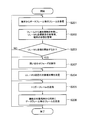
- the base station allocates resources to be used for UL-MU transmission to the selected target terminal.
- the resource is a resource block (one or a plurality of subcarriers) in the case of OFDMA, and a spatial resource (stream) in the case of MU-MIMO.
- resource allocation resources are allocated so as not to overlap between target terminals.
- resources that can be used for each terminal are determined in advance (for example, when determined at the time of association with the base station or at an arbitrary timing thereafter, or depending on the capability of the terminal, the resources that can be used are If it has been determined, etc.), a predetermined resource is allocated.
- the target terminal may be selected so that the resources that can be used for each terminal are taken into consideration and the resources that can be used between the terminals do not overlap.
- the base station may determine the PPDU length transmitted by the target terminals in common. For example, when notification information including the TXOP length and / or data amount necessary for the next transmission is received from the target terminal, the TXOP length or data amount (PPDU length or the like) notified from the target terminal is used. Thus, the PPDU length may be determined. For example, the PPDU length may be determined based on the longest TXOP or data amount among the target terminals. Details are described in the description of trigger frame generation.
- the base station when selecting the target terminal, allocating resources, and determining other parameter information, if the notification information is notified from the terminal via the existing field, is stored in the existing field Scheduling may be performed using information.
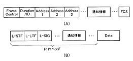
- the base station generates a trigger frame 507 when the implementation details of the UL-MU communication such as the UL-MU communication target terminal and the resources allocated to the target terminal are determined.
- the trigger frame 507 may be defined based on the general MAC frame format shown in FIG.
- the type of the Frame Control field may be a value representing a control frame
- the value of the subtype may be a newly defined value for the trigger frame.
- the frame type of the trigger frame is not a control frame but a management frame or a data frame is not excluded.
- the value of the existing standard may be used as the value of the subtype.
- information necessary for the role of the trigger frame 507 may be added as an information element to the frame body field of an existing management frame.
- the RA (reception destination address) of the trigger frame 507 may be a broadcast address or a multicast address, and the address may be set in the address 1 field.
- the TA (source address) may be the base station MAC address or BSSID.
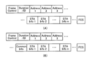
- the number of terminal information fields (STA Info. Field) corresponding to the number of UL-MU transmission target terminals is set as shown in FIG.
- STA info fields four terminal information fields (STA info fields) 1 to 4 are set.
- each terminal information field information individually notified to the terminal is set. An example of information set in the terminal information field is shown below.
- the identifier of the selected terminal is set in the terminal information field.
- the terminal identifier may be a MAC address of the terminal, an association ID (AID), or an ID unique among terminals.
- parameter information used individually by the terminal when transmitting UL-MU may be set.
- An example of parameter information is shown below.
- parameter information there is at least one of a data length that permits transmission, an error correction code scheme, PHY or MAC, or MCS (Modulation and Coding Scheme) that specifies both transmission rates.
- the data length may be the physical packet length, or may be the MAC frame length or the MSDU length if the physical header length is fixed, or the length of the other part.
- the unit of the data length may be a data size or a time length (occupied time length in space).
- the data length may be common to each terminal or may be different for each terminal.
- the maximum value of the data length (PPDU length or the like) may be determined in advance by a standard or system, and in this case, the data size is specified within a range equal to or less than the maximum value.
- the base station When determining the data length (for example, PPDU length) in the base station, for example, the largest PPDU length among the target terminals may be estimated or calculated, and the PPDU length of the terminal may be set as the uplink transmission data length. . Further, when selecting the target terminal, the base station may select terminals having the same or close PPDU length based on the PPDU length requested by the terminal. If the PPDU length transmitted for each terminal is different, the resources allocated to the terminal with the short PPDU length are wasted after the transmission of the terminal with the short PPDU length is completed until the transmission of the terminal with the long PPDU length is completed. Efficiency may also decrease. Therefore, it is possible to increase system efficiency by selecting a terminal having a short PPDU length.
- the data length for example, PPDU length
- the base station may determine the MCS for each target terminal so that the PPDU lengths of the target terminals performing UL-MU communication are equal or close to each other, and specify the MCS information in the terminal information field. For example, even if the data size is the same, if the applied MCS is different, the occupation time length is different. Therefore, when the data size is different in each terminal, the occupied time length of the PPDU in each terminal may be the same or close by adjusting the MCS.
- the MCS may designate the MCS for the field of the physical header when the MCS can be designated for some or all of the fields of the physical header.
- information on the data type to be transmitted by each terminal may be specified.
- Information of access category (AC) or traffic information (TID: Traffic ID) may be set as the data type.
- the data type to be specified may be different for each terminal or may be common to each terminal.
- a plurality of data types may be specified for one terminal.
- information on the UL-MU communication method may be specified.
- the base station adopts a mechanism capable of specifying either OFDMA or MU-MIMO and allowing the terminal to transmit UL-MU
- information specifying either OFDMA or MU-MIMO is specified.
- the terminal performs UL-MU transmission using the communication method specified by the trigger frame.
- the base station acquires a communication method that can be supported by the terminal at the time of the association process with the terminal or at an arbitrary timing thereafter, and selects the target terminal from the terminals corresponding to the communication method to be used. Good.
- information specifying one or more resources allocated to a terminal may be set in the terminal information field according to the UL-MU communication method to be used.
- information specifying one or more resource blocks assigned to a terminal may be set in the terminal information field.
- the format for specifying the resource block may be any format as long as the resource block can be specified. For example, it may be specified by a resource block number. The number of the resource block from the high frequency side or the low frequency side may be specified.
- information specifying a stream allocated to a terminal for example, information on a pattern of a preamble (a preamble for estimating a channel response) added to a frame may be specified.
- the preamble of each terminal is selected so as to be orthogonal to each other (details will be described later).
- the number of streams permitted to the terminal may be specified. It is assumed that the number of streams that can be handled by the terminal has been acquired by the base station in advance as capability information of the terminal.
- a common information field for notifying information (Common Information) between target terminals may be provided in the frame body field of the trigger frame, as shown in FIG. 11B.
- Information commonly notified to the target terminals is set. For example, when the transmission data size designated for each terminal is common, it may be set in the common information field instead of the terminal information field. Further, the UL-MU communication method to be used may be set in the common information field instead of the terminal information field.
- the group ID of the group may be specified in the common information field.
- the terminal information field and the common information field are set in the frame body field.
- part or all of the information set in the terminal information field and the common information field may be arranged in the MAC header.
- part or all of the information set in the terminal information field and the common information field may be arranged in the physical header as shown in FIG.
- the physical header in FIG. 12 includes an L-STF (Legacy-Short Training Field), an L-LTF (Legacy-Long Training Field), an L-SIG (Legacy Signal Field), a common information field, and a terminal information field.
- the terminal information field includes fields for the number of terminals.
- L-STF, L-LTF, and L-SIG are fields that can be recognized by legacy standards such as IEEE 802.11a, for example, and store information such as signal detection, frequency correction, and transmission speed.
- legacy standards such as IEEE 802.11a, for example, and store information such as signal detection, frequency correction, and transmission speed.
- the terminal information field and the common information field may be omitted from the MAC frame.
- 511 and 512 are transmitted to the base station.
- the data frames 509 to 512 are transmitted using the resource (resource block or spatial resource (corresponding to the preamble pattern)) specified by the trigger frame 507. Since the transmission timings of the data frames transmitted from the terminals 1 to 4 are synchronized with each other, the data frames 509 to 512 transmitted from the terminals 1 to 4 are transmitted by frequency multiplexing or spatial multiplexing.
- the terminals 1 to 4 may transmit a frame of a predetermined format, for example, a null packet (null packet).
- a null packet refers to a frame in which no body field exists.
- the terminals 1 to 4 may be configured not to transmit anything when there is no data to be transmitted to the base station.
- the terminal may determine that there is no data to be transmitted.
- SIFS Short Inter-frame Space
- the value of the fixed time T1 is stored in the common information field, and the terminals 1 to 4 may acquire the value of the fixed time T1 from the common information field.
- the fixed time T1 may be notified in advance by another method such as a beacon frame or another management frame.
- the terminals 1 to 4 When there are conditions specified in the terminal information field and the common information field, the terminals 1 to 4 generate and transmit data frames so as to satisfy the conditions (more specifically, generate and transmit physical packets including data frames). )I do.
- data belonging to the designated AC (here, MSDU)
- the data frame to be transmitted can include a plurality of MSDUs in the data frame such as an aggregation frame, or when a plurality of resources are specified and the MSDU can be transmitted for each resource, or belong to the specified AC
- an MSDU belonging to an AC other than the designated AC (referred to as non-designated AC) may be included.
- how many MSDUs are selected from each of the designated AC and the non-designated AC, and which AC among the non-designated ACs is selected may be determined by an arbitrary method.
- at least one MSDU belonging to the designated AC may be selected, and the MSDU may be freely selected from each AC otherwise.
- the above-described EDCA function (the function that the AC that has acquired the access right the fastest by performing the CSMA / CA procedure independently at each AC transmits) It may not be performed temporarily, or the EDCA parameter may be forcibly set to a predetermined value so that the AC can reliably acquire the access right.
- the data frame is generated and transmitted so as to satisfy the condition of the data length. For example, when the PPDU length is less than the specified value, padding data may be added to the end of the MAC frame, or no data is transmitted during the shortage time (null data) May be transmitted).
- the target terminal applies the designated MCS and generates a MAC frame or a physical packet.
- the base station receives data frames 509 to 512 (more specifically, physical packets including data frames) transmitted from the terminals 1 to 4 by OFDMA or MU-MIMO.
- data frames transmitted from terminals 1 to 4 are received by respective resource blocks, and in the case of MU-MIMO, data frames for each terminal are received from each stream.
- the base station transmits a delivery confirmation response frame 513 to the terminals 1 to 4 after the SIFS time has elapsed since the reception of each data frame.
- the SIFS time is an example, and other defined time (IFS) may be used.
- a BA frame is transmitted for each terminal in the resource block in which the data frame is received.
- the data frame transmitted to the base station includes not a A-MPDU but a normal (single) MPDU, it may be an ACK frame instead of a BA frame (in the case of a normal MPDU, a BA frame may be returned). Is possible).
- transmitting a BA (or ACK) frame in each resource block for each terminal is equivalent to transmitting an acknowledgment frame in downlink OFDMA.
- each terminal receives a BA (or ACK) frame in each resource block (in this manner, a reception filter is set so that a signal can be received in units of resource blocks).
- BA frames can be simultaneously transmitted in streams for each terminal. That is, a delivery confirmation response frame is transmitted by downlink MU-MIMO.
- Downlink MU-MIMO is defined in IEEE 802.11ac. It is not excluded that uplink transmission is OFDMA, downlink transmission is MU-MIMO, or uplink transmission is MU-MIMO, and downlink transmission is OFDAM.
- a single frame including all delivery confirmation responses for the terminals 1 to 4 may be transmitted (single user transmission).
- this frame may be called a Multi-STA BA frame.
- a Multi-TID BA frame defined in the IEEE 802.11 standard may be used.
- the BA information field of the Multi-TID BA frame is arranged for the number of terminals, and the terminal identifier (for example, AID (Association ID) or a part of AID) is set in the reserved field in the TID information subfield of each BA information field. Set.
- values may be set in the Block Ack Starting Sequence Control subfield and the Block Ack Bitmap subfield of each BA information field according to the data frames 509 to 512 to which a delivery confirmation response should be returned.
- the RA (reception destination address) of the Multi-STA BA frame may be a multicast address or a broadcast address of a group to which the terminals 1 to 4 belong in common. In this way, BA can be notified to a plurality of terminals in one frame.
- a new value may be defined for the subtype of the Frame Control field.
- the delivery confirmation response frame 513 is transmitted to the terminals 1 to 4 at a time is shown, but a method of returning a BA frame or an ACK frame to the terminals 1 to 4 in order is also possible.
- a BA frame is returned to the first terminal after completion of reception of the uplink transmitted data frame, a BAR frame is transmitted to the second and subsequent terminals, and a BA frame is received as a response. May be performed in order.
- a BA frame may be transmitted without transmitting a BAR frame, and an ACK frame may be received as a response in order.
- Which terminal is first may be notified in the common information field or the terminal information field of the trigger frame 507, or may be notified by another method. In the case of notification using the trigger frame 507, for example, the terminal assigned with the first terminal information field may perform an implicit notification with the first terminal or the like. Notification may be made by a method other than that described here.
- UL-MU transmission by the terminals 1 to 4 and transmission of a delivery confirmation response frame by the base station may be repeatedly performed.
- a preamble for estimating the uplink channel response may be added in the header of the physical packet transmitted by the terminals 1, 2, 3, and 4 by UL-MU-MIMO.
- the preambles of the terminals are set to be orthogonal to each other.
- orthogonal means that the inner product of vectors each having the value of the bit string of the preamble becomes zero.
- FIG. 13 shows a schematic configuration of a physical packet transmitted from the terminals 1 to 4 by UL-MU-MIMO.
- fields such as preambles 1 to 4 are arranged in addition to L-STF, L-LTF, and L-SIG.
- the same value is set in each terminal. That is, information necessary for each terminal is notified in advance from the base station so that the same value is set, is determined in advance by the system or standard, or both.
- “L” in L-STF, L-LTF, and L-SIG represents legacy, and these fields can be recognized by legacy terminals.
- the preambles 1 to 4 are used to spatially separate the fields after the preambles 1 to 4 between terminals.
- the base station may specify preamble patterns orthogonal to each other in the terminals 1 to 4 in the terminal information fields 1 to 4 in the notification frame.
- the base station uses the preambles 1 to 4 to calculate the uplink propagation path information between each antenna of each of the terminals 1 to 4 and the plurality of antennas of the base station, and the calculated propagation path information is By using this, the field for each terminal after the preambles 1 to 4 is decoded.
- fields storing information on MCS (Modulation Coding System) of each data field may be separately arranged.
- the terminals 1 to 4 provide the notification field for setting the notification information in the data frame, but the notification field may be provided in the management frame.
- the notification field may be provided in the management frame.
- it may be an association request frame transmitted when performing an association process with the base station, an authentication request frame, or another type of management frame.
- provision of a notification field in the control frame is not excluded.
- the notification field for setting the notification information may be provided not in the frame for single user transmission but in the frame for UL-MU transmission.
- the base station since the notification information is transmitted from each terminal to the base station in a single user transmission frame (more specifically, a physical packet including the frame) at an arbitrary timing, the base station receives the notification information.
- the base station decides to start UL-MU communication, it establishes an inquiry phase before sending a trigger frame, inquires each terminal whether it has a request for UL-MU transmission, and requests UL-MU transmission.
- the target terminal may be selected from terminals having At this time, the terminal to be inquired as to whether or not it has a request for UL-MU transmission has transmitted that there is a request for UL-MU transmission in the notification information, or has transmitted information that can specify that there is a request for this. It may be a terminal.
- the number of terminals to be inquired can be reduced, and the length of the inquiry period can be reduced.
- an efficient inquiry can be made.
- FIG. 14 shows an example of the operation sequence of the inquiry phase performed before transmitting the trigger frame. Before the inquiry fee, it is assumed that single-user communication is performed between each terminal and the base station, as before transmission of the trigger frame in FIG.
- the base station when the base station determines the start of UL-MU transmission, it determines a candidate terminal for UL-MU communication and transmits an inquiry frame 531 to one of the candidate terminals (here, terminal 1). To do.
- the terminal 1 transmits a request frame 532 including information indicating the presence / absence of a UL-MU transmission request after SIFS time from the reception of the inquiry frame 531.
- the inquiry frame 531 and the request frame 532 may be defined based on the general MAC frame format shown in FIG.
- the inquiry frame may be any type of control frame, management frame, and data frame.
- the inquiry frame is a control frame.
- a new subtype value may be defined for the inquiry frame 531.
- RA of the inquiry frame 531 is the MAC address of the terminal 1
- TA is the BSSID or MAC address of the base station.
- RA may be a broadcast address or a multicast address
- the identifier (AID or MAC address) of the terminal 1 may be set in the frame body field. Note that if the frame body field or the like has a UL-MU communication condition (for example, a communication method) determined at the present time, the condition may be set.
- the request frame 532 may be any type of control frame, management frame, and data frame. As an example, the request frame 532 is a control frame. A new subtype value may be defined for the request frame 532.
- the request frame 532 includes information for specifying the presence / absence of a UL-MU transmission request. As an example, a bit indicating the presence / absence of data for UL-MU transmission may be provided in the MAC header, body field, or physical header. Further, the request frame 532 may include the above-described notification information (see the first to ninth examples). In this case, the latest notification information can be transmitted immediately before the start of UL-MU communication.
- the base station selects other candidate terminals in order, and repeatedly transmits an inquiry frame and receives a request frame.
- an inquiry frame 533 is transmitted to the terminal 2 after the terminal 1, and the request frame 534 is received from the terminal 2 after the SIFS time.
- the inquiry frame 535 is transmitted to the terminal 3 after SIFS time from the reception of the request frame 534, and the request frame is received from the terminal 3 after the SIFS time.
- an inquiry frame is also transmitted to the terminal 4, and a request frame 536 is transmitted from the terminal 4 after the SIFS time.
- the base station determines items necessary for UL-MU transmission (selection of target terminals, etc.), generates a trigger frame 507, and transmits the trigger frame 507.
- the configuration of the trigger frame 507 and the sequence after the transmission of the trigger frame 507 are the same as those in FIG. Also in this sequence example, a notification field for setting notification information may be provided in a frame for UL-MU transmission.
- the timing at which the base station determines the start of UL-MU transmission (timing to start the inquiry phase) is not particularly specified, but the base station determines that the UL-MU is in response to a request from the terminal. It is also possible to determine the start of MU transmission.
- FIG. 15 shows a sequence example in this case.
- terminal 1 One of the terminals belonging to the base station BSS (here, terminal 1) transmits the request frame 521. More specifically, the terminal 1 holds data for uplink transmission, and acquires an access right according to CSMA / CA. That is, during the carrier sense time (standby time) between the DIFS / AIFS [AC] time and the randomly determined backoff time, carrier sense is performed, and the access right is acquired when the wireless medium is idle.
- the terminals 2 to 4 also hold data for uplink transmission and attempt to acquire the access right, but it is assumed that the terminal 1 has acquired the access right.
- the terminal 1 transmits a request frame 521 during TXOP based on the access right.
- the request frame 521 may be defined in the same manner as the request frame used in the sequence example of FIG.
- the base station determines the start of UL-MU transmission by receiving the request frame 521.
- the base station selects a candidate terminal for UL-MU communication from terminals other than terminal 1, and transmits an inquiry frame 522 including information specifying the selected candidate terminal. More specifically, the base station transmits an inquiry frame 522 after SIFS time after receiving the request frame 521.
- the inquiry frame 522 may be any type of control frame, management frame, and data frame. As an example, the inquiry frame 522 is a control frame. A new subtype value may be defined for the inquiry frame 522.
- RA of the inquiry frame 522 is a broadcast address or a multicast address
- TA is a BSSID or a MAC address of the base station.
- a field for designating a candidate terminal is provided in the frame body field, MAC header, or physical header of the inquiry frame 522, and information designating the candidate terminal is set in the field.
- fields for storing candidate terminal identifiers may be called terminal ID fields
- terminal ID fields are provided, for example, as many as the number of candidate terminals, and identifiers (AID or MAC address, etc.) of the selected candidate terminals are set in each terminal ID field.
- a group ID of a group to which each candidate terminal belongs may be set in the field. In this case, the terminal 1 may belong to the group.
- the terminal that has received the inquiry frame 522 confirms whether or not its own terminal is specified in the inquiry frame 522. For example, it is determined whether the local terminal identifier is set in any of the terminal ID fields, or whether the local terminal is specified based on whether the local terminal belongs to the group of the group ID set in the field. If the terminal (excluding terminal 1) is designated as a candidate terminal, the terminal acquires an access right based on CSMA / CA and transmits a request frame. In the example shown in the figure, the terminals 2 to 4 acquire access rights and transmit request frames 523, 525, and 527, respectively.
- the base station ends the inquiry phase when request frames are received from all candidate terminals or when a predetermined time has elapsed.
- the base station determines items necessary for the UL-MU (selection of target terminals, determination of parameter information, etc.).
- the base station acquires the access right to the wireless medium based on CSMA / CA, and transmits the trigger frame 507 generated based on the above determination.
- the sequence after the transmission of the trigger frame 507 is the same as that in FIG. Also in this sequence example, a notification field for setting notification information may be provided in a frame for UL-MU transmission.
- the sequence example of the inquiry phase shown in FIGS. 14 and 15 is an example, and a sequence other than that shown here may be used.
- the base station did not return the delivery confirmation response frame for the request frames 523, 525, and 527.
- inquiry frames are sequentially transmitted to all candidate terminals, but the base station first designates information for specifying a plurality of candidate terminals only once (identifiers or group IDs of the candidate terminals, etc. ) May be transmitted, and the terminals specified in the inquiry frame may transmit the request frames in order with a SIFS time interval.
- the inquiry frame includes information for identifying the order of candidate terminals that transmit the request frame.
- the order of the own terminal is determined, and the request frame length (the request frame length is fixed).
- the timing of the request frame transmitted by the terminal itself may be ascertained from the information such as the length and the like.
- the rank of the own terminal may be indirectly grasped according to the position of the inquiry frame in which the field storing the identifier of the own terminal is set. In addition to those described here, various sequence examples are possible as the inquiry phase.
- the terminal specified by the trigger frame can transmit a transmission request by UL-MU in response to the trigger frame.
- each terminal transmits QoS Null data and puts information on the transmission buffer (such as the amount of data in the transmission buffer) into its MAC header.
- the UL-MU PPDU length specified in the trigger frame is limited by the maximum length of the MAC header, for example.
- information for notifying that the transmission request is intended to be collected may be set.
- the terminal specified by the trigger frame may transmit the transmission buffer information when this information is set.
- a PPDU length longer than the maximum length of the MAC header may be specified.
- a transmission request (transmission buffer information) is entered in the MAC header while putting data in the frame body field so as to be within the size. Etc.) may be transmitted.
- transmission buffer information may be inserted into a frame that is UL-MUd by one or a plurality of terminals using a method called random access OFDMA described below.
- the frame transmitted from the terminal is the same as that in the above variation.
- the terminal specifies a resource block in which a terminal is not specified in a random access trigger frame (a resource block in which no terminal is specified, That is, a resource block that can be used by an arbitrary terminal is randomly selected, and a frame including a transmission request is transmitted through the selected resource block.
- the base station transmits a trigger frame, and one or more terminals simultaneously perform uplink transmission in response to the trigger frame.
- the terminal is not specified and only the resource block to be used is specified.
- a terminal may be specified for some resource blocks and a terminal may not be specified for other resource blocks.
- the terminal that receives the trigger frame (for example, a terminal for which no resource block is specified) randomly selects and uses resource blocks from resource blocks that are not specified by the terminal (terminal unspecified resource blocks). To do.
- the trigger frame including the designation of the terminal non-designated resource block is sometimes referred to as a random access trigger frame.
- a terminal not specified in the trigger frame can select a resource block at random from a terminal unspecified resource block and transmit the frame. it can.
- the method for the terminal to randomly select the resource block may be any method such as a method for selecting using a random number.
- the configuration of the random access trigger frame may be arbitrary as long as it can represent a terminal unspecified resource block. For example, in the format of FIG.
- a predetermined identifier an identifier not assigned to any terminal
- a resource block identifier are set in the STA Info field in place of the terminal identifier, and the predetermined identifier is
- the set resource block may be interpreted as a terminal unspecified resource block.
- FIG. 16 shows a flowchart of an example of the operation of the terminal according to the embodiment of the present invention.
- the operation of this terminal corresponds to the operation of the terminal in the sequence example shown in FIG. If the terminal holds data for transmission (YES in S101), the terminal acquires access rights to the wireless medium in accordance with CSMA / CA, generates a data frame including the data, and generates a data frame ( More specifically, a physical packet including a data frame is transmitted (S102).
- the physical header of the data frame or the physical packet includes the above-described notification field, and notification information (see the notification information in the first to ninth examples described above) is set in the notification field.
- the notification information is stored and transmitted in a data frame that the terminal voluntarily transmits, that is, transmitted without receiving a notification information transmission request from the base station.
- the notification information is included in the data frame, but it is also possible to send the notification information in the management frame or the control frame.
- the terminal does not receive the trigger frame from the base station (NO in S103)
- the terminal repeats the same process as described above.
- the terminal determines whether the terminal is designated as a target terminal for UL-MU transmission, and when the terminal is designated (S104).
- a data frame including data for transmission (more specifically, a physical packet including a data frame) is transmitted after a predetermined time from completion of reception of the trigger frame (S105).
- the trigger frame When a condition related to data to be transmitted or data frame is specified in the trigger frame, the data frame is generated and transmitted so as to satisfy the condition. If there is no data for transmission, a null packet may be transmitted or nothing may be transmitted.
- a data frame is transmitted here, a management frame or a control frame may be transmitted.
- a notification field for setting notification information may be provided in the data frame.
- the terminal receives a delivery confirmation frame from the base station after SIFS time from the transmission of the data frame.
- the terminal may be configured to further transmit a data frame after SIFS from reception of the delivery confirmation response frame.
- FIG. 17 shows a flowchart of an example of the operation of the base station according to the embodiment of the present invention.
- the operation of this base station corresponds to the operation of the base station in the sequence example shown in FIG.
- the base station receives a frame such as a data frame from the terminal (S201)
- the base station acquires notification information from the frame (in the case of a frame with a notification field), and based on the notification information, whether there is a UL-MU transmission request,
- the terminal status is managed (S202).
- the base station repeats the above processing until it determines to start UL-MU communication.
- the base station When the start of UL-MU communication is determined (YES in S203), necessary items such as a UL-MU communication target terminal and parameter information at the time of transmission are determined (S204), and a trigger frame is transmitted to the target terminal. (S205).
- the base station receives a frame such as a data frame transmitted simultaneously from the target terminal after a predetermined time from the transmission of the trigger frame (S206).
- the base station transmits a delivery confirmation response frame to the target terminal after SIFS time from the reception of the frame. Thereafter, the base station may return to the necessary item determination process (S204) again, may return to the trigger frame transmission process (S205), or may receive the UL-MU transmission reception process (S206). You may return. Or you may return to the process of other steps, such as step S201.
- notification information is set in a frame transmitted from a terminal to UL-MU, the base station uses the notification information to determine matters necessary for subsequent UL-MU transmission.
- FIG. 18 shows a flowchart of another example of the operation of the base station according to the embodiment of the present invention.
- the base station executes the inquiry phase (S207) as shown in FIG. 14 or FIG. 15 after determining the start of UL-MU transmission and before transmitting the trigger frame.
- S207 the inquiry phase
- a candidate terminal that performs UL-MU transmission is selected based on the notification information collected before the inquiry phase, and an inquiry frame regarding the presence / absence of an UL-MU communication execution request is transmitted to the selected candidate terminal. .
- a request frame for notifying the presence / absence of an UL-MU communication execution request from the candidate terminal is received.
- the target terminal is selected from among the candidate terminals that have notified that there is an UL-MU communication execution request. That is, it can be said that rough estimation is performed with the notification information collected before the inquiry phase, and more accurate estimation is performed by the inquiry in the inquiry phase.
- the process may return to the inquiry phase again, or may return to the processing of other steps.
- the notification information is transmitted to determine the necessary items for UL-MU communication.
- a TID that determines a terminal that is a communication target of a base station or causes a terminal to transmit data is used. It is also possible to transmit notification information from each terminal to the base station.
- the base station transmits a QoS CF-Poll frame to the terminal, and the terminal is allowed to transmit a frame during the TXOP specified in the frame.
- TID is specified in the QoS CF-Poll frame. Therefore, each terminal transmits notification information related to at least one of the first to ninth examples described above or any combination thereof as a determination material for the base station to designate at least one of the terminal and the TID. It is also possible.
- each terminal transmits a frame including notification information without receiving a request from the base station, whereby the base station can efficiently collect the notification information.
- each terminal includes notification information in a frame (data frame, association request frame, etc.) that is normally single-user transmitted to the base station on a CSMA / CA basis, so that the base station Notification information can be collected. Further, the base station can more reliably narrow down terminals having uplink data by providing an inquiry phase.
- FIG. 19 is a functional block diagram of a base station (access point) 400 according to the second embodiment.
- the access point includes a communication processing unit 401, a transmission unit 402, a reception unit 403, antennas 42A, 42B, 42C, and 42D, a network processing unit 404, a wired I / F 405, and a memory 406. .
- Access point 400 is connected to server 407 via wired I / F 405.
- the communication processing unit 401 has the same functions as the MAC processing unit 10 and the MAC / PHY management unit 60 described in the first embodiment.
- the transmission unit 402 and the reception unit 403 have the same functions as the PHY processing unit 50 and the analog processing unit 70 described in the first embodiment.
- the network processing unit 404 has the same function as that of the upper processing unit 90 described in the first embodiment.
- the communication processing unit 401 may have a buffer for exchanging data with the network processing unit 404.
- This buffer may be a volatile memory such as a DRAM or a non-volatile memory such as a NAND or MRAM.
- the network processing unit 404 controls data exchange with the communication processing unit 401, data writing / reading with the memory 406, and communication with the server 407 via the wired I / F 405.
- the network processing unit 404 may perform communication processing and application layer processing above the MAC layer, such as TCP / IP and UDP / IP.
- the operation of the network processing unit may be performed by software (program) processing by a processor such as a CPU, may be performed by hardware, or may be performed by both software and hardware.
- the communication processing unit 401 corresponds to a baseband integrated circuit
- the transmission unit 402 and the reception unit 403 correspond to an RF integrated circuit that transmits and receives a frame.
- the communication processing unit 401 and the network processing unit 404 may be configured by one integrated circuit (one chip).
- the digital domain processing part and the analog domain processing part of the transmission unit 402 and the reception unit 403 may be configured by different chips.
- the communication processing unit 401 may execute communication processing at a higher level of the MAC layer such as TCP / IP and UDP / IP. Further, although the number of antennas is four here, it is sufficient that at least one antenna is provided.
- the memory 406 stores data received from the server 407, data received by the receiving unit 402, and the like.
- the memory 406 may be, for example, a volatile memory such as a DRAM or a non-volatile memory such as NAND or MRAM. Further, it may be an SSD, HDD, SD card, eMMC or the like. Memory 406 may be external to base station 400.
- the wired I / F 405 transmits / receives data to / from the server 407.
- communication with the server 407 is performed by wire, but communication with the server 407 may be performed wirelessly.
- the server 407 is a communication device that receives a data transfer request for requesting data transmission and returns a response including the requested data.
- a data transfer request for requesting data transmission and returns a response including the requested data.
- HTTP server Web server
- FTP server or the like is assumed.
- the present invention is not limited to this as long as it has a function of returning the requested data.
- a communication device operated by a user such as a PC or a smartphone may be used. Moreover, you may communicate with the base station 400 by radio
- a packet related to the data transfer request is transmitted to the base station 400.
- the base station 400 receives this packet via the antennas 42A to 42D, and the receiving unit 403 performs physical layer processing and the communication processing unit 401 performs MAC layer processing and the like.
- the network processing unit 404 analyzes the packet received from the communication processing unit 401. Specifically, the destination IP address, the destination port number, etc. are confirmed.
- the packet data is a data transfer request such as an HTTP GET request
- the network processing unit 404 determines that the data requested by the data transfer request (for example, data existing in the URL requested by the HTTP GET request) Whether it is cached (stored) in the memory 406 is confirmed.
- the memory 406 stores a table in which a URL (or a reduced expression thereof, such as a hash value or an alternative identifier) is associated with data.
- a URL or a reduced expression thereof, such as a hash value or an alternative identifier
- the network processing unit 404 transmits a data transfer request to the server 407 via the wired I / F 405. That is, the network processing unit 404 transmits a data transfer request to the server 407 on behalf of the STA. Specifically, the network processing unit 404 generates an HTTP request, performs protocol processing such as addition of a TCP / IP header, and passes the packet to the wired I / F 405. The wired I / F 405 transmits the received packet to the server 407.
- the wired I / F 405 receives from the server 407 a packet that is a response to the data transfer request.
- the network processing unit 404 recognizes that the packet is addressed to the STA from the IP header of the packet received via the wired I / F 405 and passes the packet to the communication processing unit 401.
- the communication processing unit 401 performs MAC layer processing and the like on this packet, and the transmission unit 402 performs physical layer processing and the like, and transmits packets addressed to the STA from the antennas 42A to 42D.
- the network processing unit 404 stores the data received from the server 407 as cache data in the memory 406 in association with the URL (or a reduced representation thereof).
- the network processing unit 404 reads the data requested by the data transfer request from the memory 406 and transmits the data to the communication processing unit 401. Specifically, an HTTP header or the like is added to the data read from the memory 406, protocol processing such as addition of a TCP / IP header is performed, and the packet is transmitted to the communication processing unit 401.
- protocol processing such as addition of a TCP / IP header is performed, and the packet is transmitted to the communication processing unit 401.
- the source IP address of the packet is set to the same IP address as the server, and the source port number is also set to the same port number as the server (the destination port number of the packet transmitted by the communication terminal). Therefore, when viewed from the STA, it looks as if it is communicating with the server 407.
- the communication processing unit 401 performs MAC layer processing and the like on this packet, and the transmission unit 402 performs physical layer processing and the like, and transmits packets addressed to the STA from the antennas 42A to 42D.
- a general cache proxy that obtains data from the server 407 instead of the STA, caches the data in the memory 406, and responds to the data transfer request for the same data from the cache data in the memory 406. In other words, there is no problem with other operations.
- a terminal (STA) having a cache function can be realized with the same block configuration as FIG. In this case, the wired I / F 405 may be omitted.
- the terminal of this embodiment can be applied as the terminal of the first embodiment.
- the terminal reads data cached in the memory 406, and transmits a data frame including the read data (more specifically, a physical packet with a physical header added) to the base station.
- the data may be data acquired from the server 407 or data acquired by another method (for example, data acquired from an external device other than the server 407 or file data specified by the user).
- the terminal may generate the notification information (control information) of each example described in the first embodiment based on data for transmission to the base station cached in the memory 406.
- the terminal may transmit the generated notification information via the data frames 501, 503, and 505 of FIG. 6, or may transmit it via the data frames 509 to 512. Further, the terminal may transmit the data for transmission to the base station cached in the memory 406 via the data frames 501, 503, and 505 in FIG. 6, or by uplink multiuser transmission in FIG. The data frames 509 to 512 may be transmitted.
- a terminal In the case of a multi-hop network, a terminal has both a role of a terminal as a non-base station and a role as a base station.
- data received from another terminal may be cached in a memory in order to operate as a terminal that transfers the data to another base station.
- the base station may read data to be transmitted to the terminal from the memory 406, and generate and transmit a frame (such as a trigger frame, an inquiry frame, or a data frame) including the read data. Further, the data itself for transmission to each terminal in the memory 406 may be added to a frame such as a trigger frame.
- the data for transmission to each terminal in the memory 406 is not limited to data acquired by receiving a data transfer request from each terminal, and is not related to the data transfer request, but from an external device other than the server 407 or the server 407. It may be transmitted data. For example, push data or e-mail data addressed to each terminal may be used.
- the base station uses a downlink multi-user scheme (DL-OFDMA, DL-MU-MIMO, or a combination thereof (DL-OFDMA & DL-MU-MIMO), etc.) for a plurality of terminals, and a memory 406. Data for transmission to a plurality of terminals may be transmitted.
- DL-OFDMA downlink multi-user scheme
- DL-MU-MIMO downlink multi-user scheme
- DL-OFDMA & DL-MU-MIMO a combination thereof
- FIG. 20 shows an example of the overall configuration of a terminal or a base station.
- the terminal or base station includes one or a plurality of antennas 1 to n (n is an integer of 1 or more), a wireless LAN module 148, and a host system 149.
- the wireless LAN module 148 corresponds to the wireless communication device according to the first embodiment.
- the wireless LAN module 148 includes a host interface, and is connected to the host system 149 through the host interface. In addition to being connected to the host system 149 via a connection cable, the host system 149 may be directly connected.
- the wireless LAN module 148 is mounted on a substrate with solder or the like and is connected to the host system 149 through wiring on the substrate is also possible.
- the host system 149 communicates with an external device using the wireless LAN module 148 and the antennas 1 to n according to an arbitrary communication protocol.
- the communication protocol may include TCP / IP and higher-layer protocols.
- TCP / IP may be installed in the wireless LAN module 148, and the host system 149 may execute only higher-layer protocols. In this case, the configuration of the host system 149 can be simplified.
- This terminal is, for example, a mobile terminal, TV, digital camera, wearable device, tablet, smartphone, game device, network storage device, monitor, digital audio player, web camera, video camera, project, navigation system, external adapter, internal It may be an adapter, set top box, gateway, printer server, mobile access point, router, enterprise / service provider access point, portable device, handheld device, and the like.
- FIG. 21 shows a hardware configuration example of the wireless LAN module.
- This configuration can be applied when the wireless communication apparatus is installed in either a non-base station terminal or a base station. That is, it can be applied as an example of a specific configuration of the wireless communication apparatus illustrated in FIG.
- at least one antenna 247 is provided.
- a plurality of antennas are provided, a plurality of sets of transmission systems (216, 222 to 225), reception systems (232 to 235), PLL 242, crystal oscillator (reference signal source) 243 and switches 245 are arranged corresponding to each antenna.
- Each set may be connected to the control circuit 212.
- the PLL 242 or the crystal oscillator 243 or both correspond to the oscillator according to the present embodiment.
- the wireless LAN module (wireless communication device) includes a baseband IC (Integrated Circuit) 211, an RF (Radio Frequency) IC 221, a balun 225, a switch 245, and an antenna 247.
- a baseband IC Integrated Circuit
- RF Radio Frequency
- the baseband IC 211 includes a baseband circuit (control circuit) 212, a memory 213, a host interface 214, a CPU 215, a DAC (Digital to Analog Converter) 216, and an ADC (Analog to Digital Converter) 217.
- the baseband IC 211 and the RF IC 221 may be formed on the same substrate. Further, the baseband IC 211 and the RF IC 221 may be configured by one chip. Either or either of the DAC 216 and the ADC 217 may be arranged in the RF IC 221 or may be arranged in another IC. Further, both or either of the memory 213 and the CPU 215 may be arranged in an IC different from the baseband IC.
- the memory 213 stores data exchanged with the host system. In addition, the memory 213 stores information notified to the terminal or the base station, information notified from the terminal or the base station, or both of them.
- the memory 213 may store a program necessary for the execution of the CPU 215 and may be used as a work area when the CPU 215 executes the program.
- the memory 213 may be a volatile memory such as SRAM or DRAM, or a nonvolatile memory such as NAND or MRAM.
- the host interface 214 is an interface for connecting to the host system.
- the interface may be anything such as UART, SPI, SDIO, USB, and PCI Express.
- the CPU 215 is a processor that controls the baseband circuit 212 by executing a program.
- the baseband circuit 212 mainly performs MAC layer processing and physical layer processing.
- the baseband circuit 212, the CPU 215, or both of them correspond to a communication control device that controls communication or a control unit that controls communication.
- At least one of the baseband circuit 212 and the CPU 215 may include a clock generation unit that generates a clock, and the internal time may be managed by the clock generated by the clock generation unit.
- the baseband circuit 212 adds a physical header to the frame to be transmitted as a physical layer process, encodes, encrypts, modulates, and so on.
- a physical layer process For example, two types of digital baseband signals (hereinafter, digital I signal and digital Q signal) Signal).
- the DAC 216 performs DA conversion on the signal input from the baseband circuit 212. More specifically, the DAC 216 converts a digital I signal into an analog I signal and converts a digital Q signal into an analog Q signal. Note that there may be a case where the signal is transmitted as it is without a quadrature modulation. When a plurality of antennas are provided and transmission signals of one system or a plurality of systems are distributed and transmitted by the number of antennas, a number of DACs or the like corresponding to the number of antennas may be provided.
- the RF IC 221 is, for example, an RF analog IC, a high frequency IC, or both.
- the RF IC 221 includes a filter 222, a mixer 223, a preamplifier (PA) 224, a PLL (Phase Locked Loop) 242, a low noise amplifier (LNA), a balun 235, a mixer 233, and a filter 232. Some of these elements may be located on the baseband IC 211 or another IC.
- the filters 222 and 232 may be band pass filters or low pass filters.
- the RF IC 221 is coupled to the antenna 247 via the switch 245.
- the filter 222 extracts a signal in a desired band from each of the analog I signal and the analog Q signal input from the DAC 216.
- the PLL 242 uses the oscillation signal input from the crystal oscillator 243 and divides and / or multiplies the oscillation signal to generate a signal having a constant frequency synchronized with the phase of the input signal.
- the PLL 242 includes a VCO (Voltage Controlled Oscillator), and obtains a signal having the constant frequency by performing feedback control using the VCO based on an oscillation signal input from the crystal oscillator 243.
- the generated constant frequency signal is input to the mixer 223 and the mixer 233.
- the PLL 242 corresponds to an example of an oscillator that generates a signal having a constant frequency.
- the mixer 223 up-converts the analog I signal and the analog Q signal that have passed through the filter 222 to a radio frequency by using a constant frequency signal supplied from the PLL 242.
- the preamplifier (PA) amplifies the radio frequency analog I signal and analog Q signal generated by the mixer 223 to a desired output power.
- the balun 225 is a converter for converting a balanced signal (differential signal) into an unbalanced signal (single-ended signal).
- the RF IC 221 handles balanced signals, but since the unbalanced signal is handled from the output of the RF IC 221 to the antenna 247, these signals are converted by the balun 225.
- the switch 245 is connected to the balun 225 on the transmission side during transmission, and is connected to the balun 234 or RF IC 221 on the reception side during reception.
- the control of the switch 245 may be performed by the baseband IC 211 or the RF IC 221, or another circuit for controlling the switch 245 may exist and the switch 245 may be controlled from the circuit.
- the radio frequency analog I signal and analog Q signal amplified by the preamplifier 224 are balanced-unbalanced converted by the balun 225 and then radiated as radio waves from the antenna 247.
- the antenna 247 may be a chip antenna, an antenna formed by wiring on a printed board, or an antenna formed by using a linear conductor element.
- the LNA 234 in the RF IC 221 amplifies the signal received from the antenna 247 via the switch 245 to a level that can be demodulated while keeping the noise low.
- the balun 235 performs an unbalance-balance conversion on the signal amplified by the low noise amplifier (LNA) 234.
- the mixer 233 down-converts the received signal converted into the balanced signal by the balun 235 into a baseband using a signal having a constant frequency input from the PLL 242.
- the mixer 233 has means for generating a carrier wave that is 90 ° out of phase based on a constant frequency signal input from the PLL 242, and the received signals converted by the balun 235 are each 90 ° Quadrature demodulation is performed using a carrier wave having a phase shift to generate an I (In-phase) signal having the same phase as the received signal and a Q (Quad-phase) signal that is 90 ° behind the signal.
- the filter 232 extracts a signal having a desired frequency component from these I signal and Q signal.
- the I signal and Q signal extracted by the filter 232 are output from the RF IC 221 after the gain is adjusted.
- the ADC 217 in the baseband IC 211 AD-converts the input signal from the RF IC 221. More specifically, the ADC 217 converts the I signal into a digital I signal and converts the Q signal into a digital Q signal. There may be a case where only one system signal is received without performing quadrature demodulation.
- the baseband circuit 212 When a plurality of antennas are provided, the number of ADCs corresponding to the number of antennas may be provided. Based on the digital I signal and digital Q signal, the baseband circuit 212 performs physical layer processing such as demodulation processing, error correction code processing, and physical header processing to obtain a frame. The baseband circuit 212 performs MAC layer processing on the frame. Note that the baseband circuit 212 may be configured to perform TCP / IP processing when TCP / IP is implemented.
- FIGS. 22A and 22B are perspective views of a wireless communication terminal according to the fourth embodiment, respectively.
- the wireless communication terminal in FIG. 22A is a notebook PC 301
- the wireless communication terminal in FIG. 22B is a mobile terminal 321.
- Each corresponds to one form of a terminal (including a base station).
- the notebook PC 301 and the mobile terminal 321 are equipped with wireless communication devices 305 and 315, respectively.
- the wireless communication devices 305 and 315 the wireless communication devices mounted on the terminals (including base stations) described so far can be used.
- a wireless communication terminal equipped with a wireless communication device is not limited to a notebook PC or a mobile terminal.
- TV digital camera, wearable device, tablet, smartphone, game device, network storage device, monitor, digital audio player, web camera, video camera, project, navigation system, external adapter, internal adapter, set top box, gateway, It can also be installed in printer servers, mobile access points, routers, enterprise / service provider access points, portable devices, handheld devices, and the like.
- FIG. 23 shows an example in which the wireless communication device is mounted on a memory card.
- the memory card 331 includes a wireless communication device 355 and a memory card main body 332.
- the memory card 331 uses a wireless communication device 335 for wireless communication with an external device (such as a wireless communication terminal and / or base station).
- an external device such as a wireless communication terminal and / or base station.
- description of other elements (for example, a memory) in the memory card 331 is omitted.
- a bus, a processor unit, and an external interface unit are provided.
- the processor unit and the external interface unit are connected to the buffer via the bus.
- Firmware operates in the processor unit.
- the processor unit on which the firmware operates may be a processor that performs processing of the communication processing device or the control unit according to the present embodiment, or may be another processor that performs processing related to function expansion or change of the processing. Also good.
- the base station and / or the wireless communication terminal may include a processor unit on which firmware operates.
- the processor unit may be provided in an integrated circuit in a wireless communication device mounted on a base station or an integrated circuit in a wireless communication device mounted on a wireless communication terminal.
- a clock generation unit is provided in addition to the configuration of the wireless communication apparatus according to any one of the above-described embodiments.
- the clock generation unit generates a clock and outputs the clock from the output terminal to the outside of the wireless communication device.
- the host side and the wireless communication apparatus side can be operated in synchronization by outputting the clock generated inside the wireless communication apparatus to the outside and operating the host side with the clock output to the outside. It becomes possible.
- a power supply unit in addition to the configuration of the wireless communication apparatus according to any one of the embodiments described above, a power supply unit, a power supply control unit, and a wireless power supply unit are included.
- the power supply control unit is connected to the power supply unit and the wireless power supply unit, and performs control to select a power supply to be supplied to the wireless communication device. As described above, by providing the wireless communication apparatus with the power supply, it is possible to perform a low power consumption operation by controlling the power supply.
- a SIM card is included in addition to the configuration of the wireless communication apparatus according to any one of the embodiments described above.
- the SIM card is connected to, for example, the MAC processing unit 10, the MAC / PHY management unit 60, or the control unit 112 in the wireless communication apparatus.
- the control unit 112 in the wireless communication apparatus.
- a moving image compression / decompression unit is included in addition to the configuration of the wireless communication apparatus according to any one of the above-described embodiments.
- the moving image compression / decompression unit is connected to the bus. As described above, by providing the wireless communication device with the moving image compression / decompression unit, it is possible to easily transmit the compressed moving image and expand the received compressed moving image.
- an LED unit is included.
- the LED unit is connected to, for example, at least one of the MAC processing unit 10, the MAC / PHY management unit 60, the transmission processing circuit 113, the reception processing circuit 114, and the control unit 112. As described above, by providing the wireless communication device with the LED unit, it is possible to easily notify the user of the operation state of the wireless communication device.
- a vibrator unit is included in addition to the configuration of the wireless communication apparatus according to any one of the above-described embodiments.
- the vibrator unit is connected to, for example, at least one of the MAC processing unit 10, the MAC / PHY management unit 60, the transmission processing circuit 113, the reception processing circuit 114, and the control unit 112. As described above, by providing the radio communication device with the vibrator unit, it is possible to easily notify the user of the operation state of the radio communication device.
- a display is included in addition to the configuration of the wireless communication device (a wireless communication device of a base station or a wireless communication device of a wireless communication terminal, or both) according to any one of the embodiments described above.
- the display may be connected to the MAC processing unit of the wireless communication device via a bus (not shown).
- a bus not shown
- [1] a frame type in a wireless communication system, [2] a method of disconnecting connections between wireless communication apparatuses, [3] an access method of a wireless LAN system, and [4] a frame interval of the wireless LAN will be described.
- Frame type in communication system Generally, as described above, the frames handled on the radio access protocol in the radio communication system are roughly divided into three: data frame, management frame, and control frame. Divided into types. These types are usually indicated by a header portion provided in common between frames. As a display method of the frame type, three types may be distinguished by one field, or may be distinguished by a combination of two fields.
- the frame type is identified by two fields, Type and Subtype, in the Frame Control field in the frame header portion of the MAC frame.
- a data frame, a management frame, or a control frame is roughly classified in the Type field, and a detailed type in the roughly classified frame, for example, a Beacon frame in the management frame is identified in the Subtype field.
- the management frame is a frame used for managing a physical communication link with another wireless communication device. For example, there are a frame used for setting communication with another wireless communication device, a frame for releasing a communication link (that is, disconnecting), and a frame related to a power saving operation in the wireless communication device. .
- the data frame is a frame for transmitting data generated inside the wireless communication device to the other wireless communication device after establishing a physical communication link with the other wireless communication device.
- Data is generated in an upper layer of the present embodiment, for example, generated by a user operation.
- the control frame is a frame used for control when a data frame is transmitted / received (exchanged) to / from another wireless communication apparatus.
- the wireless communication apparatus receives a data frame or a management frame
- the response frame transmitted for confirmation of delivery belongs to the control frame.
- the response frame is, for example, an ACK frame or a BlockACK frame.
- RTS frames and CTS frames are also control frames.
- the association request frame and association response frame used in the process are management frames, and the association request. Since the frame and the Association Response frame are unicast management frames, the reception side wireless communication terminal is requested to transmit an ACK frame as a response frame, and the ACK frame is a control frame as described above.
- connection disconnection method between wireless communication devices There are an explicit method and an implicit method for disconnection (release) of a connection.
- an explicit method one of the wireless communication apparatuses that have established a connection transmits a frame for disconnection.
- a deauthentication frame is classified as a management frame.
- the wireless communication device that receives a frame for disconnecting a connection disconnects the connection when the frame is received. judge. After that, if it is a non-base station wireless communication terminal, it returns to the initial state in the communication phase, for example, the state of searching for a connected BSS.
- the connection management Delete information related to the wireless communication terminal from the table. For example, when assigning an AID to a wireless communication terminal that joins the BSS in the association process at the stage where the wireless communication base station has permitted the connection, the holding information associated with the AID of the wireless communication terminal that has disconnected the connection. May be deleted, and the AID may be released and assigned to another newly joined wireless communication terminal.
- a frame transmission transmission of a data frame and a management frame, or transmission of a response frame to a frame transmitted by the device itself
- a wireless communication device of a connection partner with which a connection has been established. If not, it is determined whether the connection is disconnected.
- the connection is disconnected as described above, such that the communication distance is away from the connection-destination wireless communication device, and the wireless signal cannot be received or decoded. This is because a wireless link cannot be secured. That is, it is impossible to expect reception of a frame for disconnecting the connection.
- a timer is used as a specific example of determining disconnection by an implicit method. For example, when transmitting a data frame requesting a delivery confirmation response frame, a first timer (for example, a retransmission timer for a data frame) that limits a retransmission period of the frame is started, and until the first timer expires (that is, If a delivery confirmation response frame is not received (until the desired retransmission period elapses), retransmission is performed. The first timer is stopped when a delivery confirmation response frame to the frame is received.
- a first timer for example, a retransmission timer for a data frame
- the first timer is stopped when a delivery confirmation response frame to the frame is received.
- the first timer expires without receiving the delivery confirmation response frame, for example, it is confirmed whether the other party's wireless communication device still exists (within the communication range) (in other words, the wireless link can be secured).
- a second timer for limiting the retransmission period of the frame (for example, a retransmission timer for the management frame) is started at the same time. Similar to the first timer, the second timer also performs retransmission if it does not receive an acknowledgment frame for the frame until the second timer expires, and determines that the connection has been disconnected when the second timer expires. . When it is determined that the connection has been disconnected, a frame for disconnecting the connection may be transmitted.
- the third timer is started. Whenever a new frame is received from the connection partner wireless communication device, the third timer is stopped and restarted from the initial value. When the third timer expires, a management frame is transmitted to confirm whether the other party's wireless communication device still exists (within the communication range) (in other words, whether the wireless link has been secured) as described above. At the same time, a second timer (for example, a retransmission timer for management frames) that limits the retransmission period of the frame is started.
- a second timer for example, a retransmission timer for management frames
- the acknowledgment response frame to the frame is not received until the second timer expires, retransmission is performed, and if the second timer expires, it is determined that the connection has been disconnected.
- a frame for disconnecting the connection may be transmitted when it is determined that the connection has been disconnected.
- the latter management frame for confirming whether the wireless communication apparatus of the connection partner still exists may be different from the management frame in the former case.
- the timer for limiting the retransmission of the management frame is the same as that in the former case as the second timer, but a different timer may be used.
- [3] Access method of wireless LAN system For example, there is a wireless LAN system that is assumed to communicate or compete with a plurality of wireless communication devices.
- the IEEE 802.11 wireless LAN uses CSMA / CA (Carrier Sense Multiple Access with Carrier Avoidance) as a basic access method.
- CSMA / CA Carrier Sense Multiple Access with Carrier Avoidance
- the transmission is performed simultaneously by a plurality of wireless communication devices grasping the transmission of the wireless communication device, and as a result
- the radio signal collides and frame transmission fails.
- the transmissions by a plurality of wireless communication devices that grasp the transmission of the wireless communication device are stochastically dispersed. Therefore, if there is one wireless communication device that has drawn the earliest time in the random time, the frame transmission of the wireless communication device is successful, and frame collision can be prevented. Since acquisition of transmission rights is fair among a plurality of wireless communication devices based on a random value, the method employing Carrier Aviation is a method suitable for sharing a wireless medium between a plurality of wireless communication devices. be able to.
- the IEEE 802.11 wireless LAN frame interval will be described.
- the frame interval used in the IEEE 802.11 wireless LAN is as follows: distributed coordination function inter frame space (DIFS), arbitration inter frame space (AIFS), point coordination function intra interface space interface (IFS).
- DIFS distributed coordination function inter frame space
- AIFS arbitration inter frame space
- IFS point coordination function intra interface space interface
- RIFS reduced interface space
- the definition of the frame interval is defined as a continuous period to be opened after confirming the carrier sense idle before transmission in the IEEE 802.11 wireless LAN, and a strict period from the previous frame is not discussed. Therefore, in the description of the IEEE802.11 wireless LAN system here, the definition follows.
- the waiting time for random access based on CSMA / CA is the sum of a fixed time and a random time, and it can be said that such a definition is used to clarify the fixed time.
- DIFS and AIFS are frame intervals used when attempting to start frame exchange during a contention period competing with other wireless communication devices based on CSMA / CA.
- the DIFS is used when priority according to the traffic type (Traffic Identifier: TID) is provided when there is no distinction of the priority according to the traffic type.
- TID Traffic Identifier
- AIFS Since operations related to DIFS and AIFS are similar, the following description will be mainly made using AIFS.
- access control including the start of frame exchange is performed in the MAC layer.
- QoS Quality of Service
- the traffic type is notified together with the data, and the data is classified according to the priority at the time of access based on the traffic type.
- This class at the time of access is called an access category (AC). Therefore, an AIFS value is provided for each access category.
- PIFS is a frame interval for enabling access with priority over other competing wireless communication devices, and has a shorter period than either of the values of DIFS and AIFS.
- SIFS is a frame interval that can be used when transmitting a control frame of a response system or when frame exchange is continued in a burst after acquiring an access right once.
- the EIFS is a frame interval that is activated when frame reception fails (it is determined that the received frame is an error).
- the RIFS is a frame interval that can be used when a plurality of frames are continuously transmitted to the same wireless communication device in bursts after acquiring the access right once. Do not request a response frame.
- FIG. 24 shows an example of a frame exchange in a contention period based on random access in the IEEE 802.11 wireless LAN. *
- the random time is obtained by multiplying a pseudo-random integer derived from a uniform distribution between contention windows (Content Window: CW) given by an integer from 0 to a slot time.
- CW multiplied by slot time is referred to as CW time width.
- the initial value of CW is given by CWmin, and every time retransmission is performed, the value of CW is increased until it reaches CWmax.
- Both CWmin and CWmax have values for each access category, similar to AIFS.
- the wireless communication apparatus that is the transmission destination of W_DATA1 if the data frame is successfully received and the data frame is a frame that requests transmission of a response frame, the occupation of the physical packet that includes the data frame on the wireless medium is completed.
- a response frame (W_ACK1) is transmitted after SIFS time from the time.
- the wireless communication apparatus that has transmitted W_DATA1 transmits the next frame (for example, W_DATA2) after SIFS time from the end of occupation of the physical packet containing W_ACK1 on the wireless medium if it is within the transmission burst time limit when W_ACK1 is received. can do.
- AIFS, DIFS, PIFS, and EIFS are functions of SIFS and slot time, and SIFS and slot time are defined for each physical layer.
- Parameters for which values are provided for each access category, such as AIFS, CWmin, and CWmax, can be set for each communication group (Basic Service Set (BSS) in the IEEE 802.11 wireless LAN), but default values are set. .
- BSS Base Service Set
- the SIFS is 16 ⁇ s and the slot time is 9 ⁇ s.
- the PIFS is 25 ⁇ s
- the DIFS is 34 ⁇ s
- the frame interval of the access category BACKGROUND (AC_BK) in AIFS is 79 ⁇ s by default.
- the frame interval of BEST EFFORT (AC_BE) has a default value of 43 ⁇ s
- the frame interval of VIDEO (AC_VI) and VOICE (AC_VO) has a default value of 34 ⁇ s
- the default values of CWmin and CWmax are 31 and 1023 for AC_BK and AC_BE, respectively.
- AC_VI is 15 and 31
- AC_VO is 7 and 15.
- the EIFS is basically the sum of the time lengths of response frames in the case of transmission at SIFS and DIFS at the slowest required physical rate. Note that in a wireless communication apparatus capable of efficiently taking EIFS, the occupation time length of a physical packet carrying a response frame to the physical packet that activated EIFS is estimated, and the sum of SIFS, DIFS, and the estimated time may be used. it can.
- processors may include general purpose processors, central processing units (CPUs), microprocessors, digital signal processors (DSPs), controllers, microcontrollers, state machines, and the like.
- processors may refer to an application specific integrated circuit, a field programmable gate array (FPGA), a programmable logic circuit (PLD), or the like.
- FPGA field programmable gate array
- PLD programmable logic circuit
- processor may refer to a combination of processing devices such as a plurality of microprocessors, a combination of a DSP and a microprocessor, and one or more microprocessors that cooperate with a DSP core.
- the term “memory” may encompass any electronic component capable of storing electronic information.
- “Memory” means random access memory (RAM), read only memory (ROM), programmable read only memory (PROM), erasable programmable read only memory (EPROM), electrically erasable PROM (EEPROM), non-volatile It may refer to random access memory (NVRAM), flash memory, magnetic or optical data storage, which can be read by the processor. If the processor reads and / or writes information to the memory, the memory can be said to be in electrical communication with the processor. The memory may be integrated into the processor, which again can be said to be in electrical communication with the processor.
- the frame described in each embodiment may refer to not only a frame called in the IEEE 802.11 standard, but also a packet called a packet such as Null Data Packet.
- these frames or the Xth frames may be the same or different.
- X can be set to any value depending on the situation.
- the present invention is not limited to the above-described embodiment as it is, and can be embodied by modifying constituent elements without departing from the scope of the invention in the implementation stage.
- various inventions can be formed by appropriately combining a plurality of components disclosed in the embodiment. For example, some components may be deleted from all the components shown in the embodiment.
- constituent elements over different embodiments may be appropriately combined.
- MAC processing unit 20 MAC common processing unit 30: transmission processing unit 40: reception processing unit 50: PHY processing unit 60: MAC / PHY management unit 70: analog processing unit (analog processing units 1 to N) 80: Antenna (Antenna 1 to N) 90: Host processing unit 148: Wireless LAN module 149: Host system 211: Baseband IC 213: Memory 214: Host interface 215: CPU 216: DAC 217: ADC 221: RF IC 222, 232: Filter 223, 233: Mixer 224, 234: Amplifier 225, 235: Balun 242: PLL 243: Crystal oscillator 247: Antenna 245: Switch 301: Notebook PC 305, 315, 355: wireless communication device 321: mobile terminal 331: memory card 332: memory card main body 42A, 42B, 42C, 42D: antenna 401: communication processing unit 402: transmission unit 403: reception unit 404: network processing unit
Abstract
Le problème à résoudre par la présente invention est de réaliser une transmission multiplexée par l'utilisateur tout en empêchant une réduction de l'efficacité du système. La solution selon l'invention concerne un dispositif de communication sans fil qui, selon un mode de réalisation, est pourvu d'un premier circuit qui transmet une première trame, qui comprend un premier élément d'information requis pour une transmission en liaison montante multiplexée par un utilisateur, sans réception d'une demande de transmission pour le premier élément d'information.
Priority Applications (5)
| Application Number | Priority Date | Filing Date | Title |
|---|---|---|---|
| JP2017516610A JP6568584B2 (ja) | 2015-05-07 | 2016-04-28 | 無線通信装置、無線通信端末および無線通信方法 |
| EP16789553.1A EP3293902B1 (fr) | 2015-05-07 | 2016-04-28 | Dispositif de communication sans fil |
| US15/804,766 US10615854B2 (en) | 2015-05-07 | 2017-11-06 | Wireless communication device, wireless communication terminal and wireless communication method |
| US16/800,234 US11356154B2 (en) | 2015-05-07 | 2020-02-25 | Wireless communication device, wireless communication terminal and wireless communication method |
| US17/739,423 US11923926B2 (en) | 2015-05-07 | 2022-05-09 | Wireless communication device, wireless communication terminal and wireless communication method |
Applications Claiming Priority (4)
| Application Number | Priority Date | Filing Date | Title |
|---|---|---|---|
| JP2015094715 | 2015-05-07 | ||
| JP2015-094715 | 2015-05-07 | ||
| JP2015-097748 | 2015-05-12 | ||
| JP2015097748 | 2015-05-12 |
Related Child Applications (1)
| Application Number | Title | Priority Date | Filing Date |
|---|---|---|---|
| US15/804,766 Continuation US10615854B2 (en) | 2015-05-07 | 2017-11-06 | Wireless communication device, wireless communication terminal and wireless communication method |
Publications (1)
| Publication Number | Publication Date |
|---|---|
| WO2016178417A1 true WO2016178417A1 (fr) | 2016-11-10 |
Family
ID=57217640
Family Applications (1)
| Application Number | Title | Priority Date | Filing Date |
|---|---|---|---|
| PCT/JP2016/063504 WO2016178417A1 (fr) | 2015-05-07 | 2016-04-28 | Dispositif de communication sans fil |
Country Status (4)
| Country | Link |
|---|---|
| US (3) | US10615854B2 (fr) |
| EP (1) | EP3293902B1 (fr) |
| JP (2) | JP6568584B2 (fr) |
| WO (1) | WO2016178417A1 (fr) |
Cited By (4)
| Publication number | Priority date | Publication date | Assignee | Title |
|---|---|---|---|---|
| KR20170093187A (ko) * | 2014-12-02 | 2017-08-14 | 오시아 인크. | 무선 전력 전달 환경에서 비콘 신호를 인코딩하는 기법 |
| EP3355640A1 (fr) * | 2017-01-30 | 2018-08-01 | Kabushiki Kaisha Toshiba | Dispositif et procédé de communication sans fil |
| JP2020072310A (ja) * | 2018-10-29 | 2020-05-07 | キヤノン株式会社 | 通信装置、通信装置の制御方法、およびプログラム |
| WO2020213579A1 (fr) * | 2019-04-16 | 2020-10-22 | 日本電信電話株式会社 | Système de communication sans fil et procédé de communication sans fil |
Families Citing this family (6)
| Publication number | Priority date | Publication date | Assignee | Title |
|---|---|---|---|---|
| EP3294032B1 (fr) | 2015-05-07 | 2021-03-10 | Kabushiki Kaisha Toshiba, Inc. | Terminal de communication sans fil et procédé de communication sans fil |
| US11356331B2 (en) * | 2019-06-27 | 2022-06-07 | Cisco Technology, Inc. | Wireless configuration diagnosis framework |
| JP2023043893A (ja) * | 2020-02-18 | 2023-03-30 | シャープ株式会社 | ステーション装置、通信方法 |
| JP2023043891A (ja) * | 2020-02-18 | 2023-03-30 | シャープ株式会社 | ステーション装置、通信方法 |
| CN115314109B (zh) * | 2022-04-12 | 2023-08-01 | 中国人民解放军战略支援部队航天工程大学 | 一种用fpga实现的多通道光纤传输 |
| KR102497152B1 (ko) * | 2022-10-04 | 2023-02-08 | 국방과학연구소 | 복수의 단말의 데이터 전송을 관리하는 장치 및 그의 동작 방법 |
Citations (4)
| Publication number | Priority date | Publication date | Assignee | Title |
|---|---|---|---|---|
| WO2011038154A1 (fr) * | 2009-09-23 | 2011-03-31 | Qualcomm Incorporated | Planification d'opportunité de transmissions sdma par liaison montante |
| US20120060075A1 (en) * | 2010-09-08 | 2012-03-08 | Gong Michelle X | Techniques for ul mu mimo signaling and error handling |
| US20140126509A1 (en) * | 2011-06-15 | 2014-05-08 | Lg Electronics Inc. | Method for transmitting and receiving data unit based on uplink multiple user multiple input multiple output transmission and apparatus for the same |
| US20150063111A1 (en) * | 2013-08-28 | 2015-03-05 | Qualcomm Incorporated | Methods and apparatus for multiple user uplink |
Family Cites Families (72)
| Publication number | Priority date | Publication date | Assignee | Title |
|---|---|---|---|---|
| US4099180A (en) | 1977-03-02 | 1978-07-04 | General Signal Corporation | Geographic gain time control |
| JP2003061136A (ja) | 2001-08-21 | 2003-02-28 | Matsushita Electric Ind Co Ltd | 圏外無線通信システムおよび移動局 |
| JP4179034B2 (ja) | 2003-04-18 | 2008-11-12 | ソニー株式会社 | 通信システム、通信装置、通信方法及びプログラム |
| US6993342B2 (en) | 2003-05-07 | 2006-01-31 | Motorola, Inc. | Buffer occupancy used in uplink scheduling for a communication device |
| EP1699175A4 (fr) | 2003-12-26 | 2011-07-27 | Panasonic Corp | Systeme d'acces radio |
| DE602004022505D1 (de) | 2004-02-20 | 2009-09-24 | Alcatel Lucent | Verfahren zur Bereitstellung von differentiertem Verkehr in einer drahtlosen Lokalbereichsnetzwerkumgebung und korrespondierende drahtlose Lokalbereichsnetzwerkstation |
| US7577113B2 (en) | 2005-03-31 | 2009-08-18 | Intel Corporation | Device, system and method for coordinating power saving with access categories |
| WO2007001267A1 (fr) | 2005-06-20 | 2007-01-04 | Mitsubishi Electric Research Laboratories | Protocole efficient de transmission de donnees en sens inverse |
| US8786072B2 (en) | 2007-02-27 | 2014-07-22 | International Rectifier Corporation | Semiconductor package |
| US8856633B2 (en) | 2007-10-03 | 2014-10-07 | Qualcomm Incorporated | Millimeter-wave communications for peripheral devices |
| JP5166125B2 (ja) | 2008-06-05 | 2013-03-21 | 株式会社東芝 | 無線通信装置、方法およびプログラム |
| US8743793B2 (en) | 2008-07-14 | 2014-06-03 | Qualcomm Incorporated | Systems and methods for providing a separate contention window allowing allocations for pending uplink SDMA transmission opportunities |
| JP5091844B2 (ja) | 2008-12-01 | 2012-12-05 | 株式会社東芝 | 無線基地局、無線端末局、無線通信システムおよび無線通信方法 |
| JP5149136B2 (ja) | 2008-12-12 | 2013-02-20 | 株式会社東芝 | 無線通信装置、無線基地局、無線端末局、及び無線通信方法 |
| JP5332854B2 (ja) | 2009-04-20 | 2013-11-06 | ソニー株式会社 | 無線送信機、無線送信方法、無線受信機および無線受信方法 |
| US8665767B2 (en) | 2009-08-25 | 2014-03-04 | Qualcomm Incorporated | Method and apparatus for multiple-user communication in a client initiated communication transmission scheme |
| US20150049727A1 (en) | 2009-09-23 | 2015-02-19 | Qualcomm Incorporated | Uplink sdma transmit opportunity scheduling |
| WO2011054912A1 (fr) | 2009-11-06 | 2011-05-12 | Alcatel Lucent | Système et procédé de préanalyse et de mise en mémoire cache de contenu |
| US9357565B2 (en) | 2010-03-09 | 2016-05-31 | Qualcomm Incorporated | Multi-user uplink communication using EDCA with polling |
| US8730993B2 (en) | 2010-07-12 | 2014-05-20 | Intel Corporation | Methods and apparatus for uplink MU MIMO scheduling |
| KR101521080B1 (ko) | 2011-04-15 | 2015-05-18 | 인텔 코포레이션 | 무선 네트워크에서 채널 액세스를 위한 방법 및 장치 |
| JP5713844B2 (ja) | 2011-08-25 | 2015-05-07 | 株式会社東芝 | 無線通信装置及び干渉回避方法 |
| JP6122039B2 (ja) | 2012-03-01 | 2017-04-26 | インターデイジタル パテント ホールディングス インコーポレイテッド | Wlanシステムにおけるマルチユーザ並列チャネルアクセス |
| US9608789B2 (en) | 2012-05-11 | 2017-03-28 | Interdigital Patent Holdings, Inc. | Method and apparatus for transmitting acknowledgements in response to received frames |
| US9232502B2 (en) | 2012-10-31 | 2016-01-05 | Samsung Electronics Co., Ltd. | Method and system for uplink multi-user multiple-input-multiple-output communication in wireless networks |
| US9419752B2 (en) * | 2013-03-15 | 2016-08-16 | Samsung Electronics Co., Ltd. | Transmission opportunity operation of uplink multi-user multiple-input-multiple-output communication in wireless networks |
| CN104066145B (zh) | 2013-03-22 | 2017-08-29 | 华为技术有限公司 | Ofdma竞争方法及接入点 |
| WO2014190284A1 (fr) | 2013-05-24 | 2014-11-27 | Qualcomm Incorporated | Réutilisation de canal basée sur opportunité de transmission (txop) |
| US9455808B2 (en) | 2013-07-03 | 2016-09-27 | Broadcom Corporation | Wireless communication system with coordinated multipoint operation and methods for use therewith |
| JPWO2015025348A1 (ja) | 2013-08-19 | 2017-03-02 | 富士通株式会社 | 移動通信システム、移動通信システムにおける通信方法、及び端末装置 |
| US20150063190A1 (en) | 2013-08-28 | 2015-03-05 | Qualcomm Incorporated | Methods and apparatus for multiple user uplink |
| US9295074B2 (en) | 2013-09-10 | 2016-03-22 | Samsung Electronics Co., Ltd. | Acknowledgement, error recovery and backoff operation of uplink multi-user multiple-input-multiple-output communication in wireless networks |
| US10230497B2 (en) | 2013-11-01 | 2019-03-12 | Qualcomm Incorporated | Protocols for multiple user frame exchanges |
| US9961510B2 (en) | 2013-11-01 | 2018-05-01 | Qualcomm Incorporated | Protocols for multiple user frame exchanges |
| CN105794296A (zh) | 2013-11-07 | 2016-07-20 | Lg电子株式会社 | 在无线lan中接收多用户上行链路的方法和设备 |
| US20150223169A1 (en) | 2014-02-06 | 2015-08-06 | Nokia Corporation | Method, apparatus, and computer program product for initial indication of block allocation within page for wireless networks |
| US20150245243A1 (en) | 2014-02-24 | 2015-08-27 | Qualcomm Incorporated | Short request to send frame |
| US20150245244A1 (en) | 2014-02-24 | 2015-08-27 | Qualcomm Incorporated | Short request to send frame |
| CN104202822A (zh) | 2014-04-30 | 2014-12-10 | 中兴通讯股份有限公司 | 一种信道接入方法、系统以及站点 |
| US10349288B2 (en) | 2014-06-02 | 2019-07-09 | Lg Electronics Inc. | Method and device for receiving frame |
| KR102469965B1 (ko) * | 2014-06-08 | 2022-11-23 | 엘지전자 주식회사 | 무선랜 시스템에서 상향링크 다중 사용자 전송 방법 및 이를 위한 장치 |
| KR20170017894A (ko) | 2014-06-09 | 2017-02-15 | 엘지전자 주식회사 | 프레임을 수신하는 방법 및 장치 |
| WO2015192070A1 (fr) | 2014-06-12 | 2015-12-17 | Narvell Semiconductor, Inc. | Attribution de sous-canal dans un wlan à multiplexage par répartition orthogonale de la fréquence |
| US10009930B2 (en) | 2014-06-19 | 2018-06-26 | Lg Electronics Inc. | Method and apparatus for transmitting frame |
| WO2015199306A1 (fr) | 2014-06-26 | 2015-12-30 | 엘지전자(주) | Procédé de transmission de données de liaison montante multi-utilisateur dans un système de communications sans fil, et dispositif correspondant |
| USRE49420E1 (en) | 2014-08-22 | 2023-02-14 | Lg Electronics Inc. | Method for uplink multi-user transmission in wireless communication system and apparatus therefor |
| US9532370B2 (en) | 2014-08-29 | 2016-12-27 | Intel Corporation | Apparatus, method and system of controlling communications of a multi-radio device |
| CN105471553B (zh) | 2014-09-12 | 2020-05-05 | 中兴通讯股份有限公司 | 一种实现并行多用户数据传输的方法及主节点 |
| US9894641B2 (en) | 2014-09-26 | 2018-02-13 | Qualcomm, Incorporated | Methods and apparatus for implementing multiple user uplink medium access control protocols in a wireless network |
| KR20160045023A (ko) | 2014-10-16 | 2016-04-26 | 뉴라컴 인코포레이티드 | 고효율 무선랜에서 상향링크 채널 액세스 방법 및 장치 |
| JP2018011093A (ja) | 2014-11-18 | 2018-01-18 | 株式会社東芝 | 無線通信端末、メモリーカード、無線通信装置、無線通信方法および無線通信システム |
| WO2016108633A1 (fr) | 2014-12-30 | 2016-07-07 | 엘지전자 주식회사 | Procédé et dispositif permettant d'effectuer une transmission de liaison montante après la réception d'une trame de déclenchement dans un système de lan sans fil |
| US10257854B2 (en) | 2015-02-02 | 2019-04-09 | Samsung Electronics Co., Ltd. | Management of uplink multi-user transmissions in wireless local area networks |
| WO2016129979A1 (fr) | 2015-02-13 | 2016-08-18 | 주식회사 윌러스표준기술연구소 | Terminal de communication sans fil pour transmission de liaison montante multi-utilisateur, et un procédé de communication sans fil |
| WO2016141570A1 (fr) | 2015-03-11 | 2016-09-15 | 华为技术有限公司 | Procédé de transmission ofdma, point d'accès (ap) et station |
| EP3289713A1 (fr) | 2015-04-29 | 2018-03-07 | Interdigital Patent Holdings, Inc. | Opportunité d'émission déclenchée et procédures d'ack multiutilisateurs dans les systèmes de wlan |
| EP3294032B1 (fr) | 2015-05-07 | 2021-03-10 | Kabushiki Kaisha Toshiba, Inc. | Terminal de communication sans fil et procédé de communication sans fil |
| US10492223B2 (en) | 2015-05-21 | 2019-11-26 | Newracom, Inc. | Channel access for multi-user communication |
| US10116361B2 (en) | 2015-06-02 | 2018-10-30 | Newracom, Inc. | Methods for uplink multiuser signaling and transmission |
| US9686071B2 (en) | 2015-06-23 | 2017-06-20 | Intel Corporation | Opportunistic full-duplex communications |
| EP3157300B1 (fr) | 2015-07-31 | 2021-03-31 | Lg Electronics Inc. | Procédé de transmission de données dans un système de communications sans fil, et appareil associé |
| US10728799B2 (en) | 2015-10-23 | 2020-07-28 | Lg Electronics Inc. | Method for transmitting data in wireless communication system and device therefor |
| US10230498B2 (en) | 2015-11-13 | 2019-03-12 | Microsoft Technology Licensing, Llc | Data acknowledgment to multiple devices |
| US10455557B2 (en) | 2016-02-05 | 2019-10-22 | Lg Electronics Inc. | Method of supporting for uplink multi-user transmission in wireless area network system |
| GB2552497B (en) | 2016-07-25 | 2020-12-02 | Canon Kk | Transmission method for trigger frame by a 802.11ax access-point |
| GB2555455B (en) | 2016-10-28 | 2020-02-26 | Canon Kk | QoS management for multi-user EDCA transmission mode in 802.11ax networks |
| US9900871B1 (en) | 2017-01-05 | 2018-02-20 | Lg Electronics Inc. | Method for transmitting uplink frame in wireless LAN system and wireless device using the same |
| US10313860B2 (en) | 2017-03-02 | 2019-06-04 | Blackberry Limited | Method and system for wakeup trigger by out-of-band communication |
| GB2560540B (en) | 2017-03-14 | 2019-05-01 | Canon Kk | Queues management for multi-user and single user edca transmission mode in wireless networks |
| US10588168B2 (en) | 2017-05-15 | 2020-03-10 | Apple Inc. | Peer-to-peer transmission pause indication |
| US20190098483A1 (en) | 2017-11-27 | 2019-03-28 | Intel IP Corporation | Enhanced bluetooth mechanism for triggering wi-fi radios |
| US10849157B1 (en) | 2019-05-23 | 2020-11-24 | Cisco Technology, Inc. | Random access trigger frame based uplink OFDMA scheduling mechanism |
-
2016
- 2016-04-28 WO PCT/JP2016/063504 patent/WO2016178417A1/fr unknown
- 2016-04-28 EP EP16789553.1A patent/EP3293902B1/fr active Active
- 2016-04-28 JP JP2017516610A patent/JP6568584B2/ja active Active
-
2017
- 2017-11-06 US US15/804,766 patent/US10615854B2/en active Active
-
2019
- 2019-07-25 JP JP2019137124A patent/JP6815449B2/ja active Active
-
2020
- 2020-02-25 US US16/800,234 patent/US11356154B2/en active Active
-
2022
- 2022-05-09 US US17/739,423 patent/US11923926B2/en active Active
Patent Citations (4)
| Publication number | Priority date | Publication date | Assignee | Title |
|---|---|---|---|---|
| WO2011038154A1 (fr) * | 2009-09-23 | 2011-03-31 | Qualcomm Incorporated | Planification d'opportunité de transmissions sdma par liaison montante |
| US20120060075A1 (en) * | 2010-09-08 | 2012-03-08 | Gong Michelle X | Techniques for ul mu mimo signaling and error handling |
| US20140126509A1 (en) * | 2011-06-15 | 2014-05-08 | Lg Electronics Inc. | Method for transmitting and receiving data unit based on uplink multiple user multiple input multiple output transmission and apparatus for the same |
| US20150063111A1 (en) * | 2013-08-28 | 2015-03-05 | Qualcomm Incorporated | Methods and apparatus for multiple user uplink |
Non-Patent Citations (2)
| Title |
|---|
| "Issues on UL-OFDMA Transmission", IEEE 802.11- 14/1431R0, 3 November 2014 (2014-11-03), XP055326477, Retrieved from the Internet <URL:https://mentor.ieee.org/802.11/dcn/14/11-14-1431-00-00ax-issues-on-ul-ofdma.pptx> * |
| See also references of EP3293902A4 * |
Cited By (11)
| Publication number | Priority date | Publication date | Assignee | Title |
|---|---|---|---|---|
| KR20170093187A (ko) * | 2014-12-02 | 2017-08-14 | 오시아 인크. | 무선 전력 전달 환경에서 비콘 신호를 인코딩하는 기법 |
| KR101957077B1 (ko) | 2014-12-02 | 2019-03-11 | 오시아 인크. | 무선 전력 전달 환경에서 비콘 신호를 인코딩하는 기법 |
| US10517127B2 (en) | 2014-12-02 | 2019-12-24 | Ossia Inc. | Techniques for encoding beacon signals in wireless power delivery environments |
| US11083030B2 (en) | 2014-12-02 | 2021-08-03 | Ossia Inc. | Techniques for encoding beacon signals in wireless power delivery environments |
| US11638314B2 (en) | 2014-12-02 | 2023-04-25 | Ossia Inc. | Techniques for encoding beacon signals in wireless power delivery environments |
| EP3355640A1 (fr) * | 2017-01-30 | 2018-08-01 | Kabushiki Kaisha Toshiba | Dispositif et procédé de communication sans fil |
| JP2020072310A (ja) * | 2018-10-29 | 2020-05-07 | キヤノン株式会社 | 通信装置、通信装置の制御方法、およびプログラム |
| JP7208763B2 (ja) | 2018-10-29 | 2023-01-19 | キヤノン株式会社 | 通信装置、通信装置の制御方法、およびプログラム |
| WO2020213579A1 (fr) * | 2019-04-16 | 2020-10-22 | 日本電信電話株式会社 | Système de communication sans fil et procédé de communication sans fil |
| JP2020178194A (ja) * | 2019-04-16 | 2020-10-29 | 日本電信電話株式会社 | 無線通信システムおよび無線通信方法 |
| JP7167827B2 (ja) | 2019-04-16 | 2022-11-09 | 日本電信電話株式会社 | 無線通信システムおよび無線通信方法 |
Also Published As
| Publication number | Publication date |
|---|---|
| JPWO2016178417A1 (ja) | 2018-03-29 |
| JP2020005266A (ja) | 2020-01-09 |
| JP6568584B2 (ja) | 2019-08-28 |
| US20220263550A1 (en) | 2022-08-18 |
| US10615854B2 (en) | 2020-04-07 |
| EP3293902B1 (fr) | 2023-05-31 |
| EP3293902A4 (fr) | 2018-12-12 |
| EP3293902A1 (fr) | 2018-03-14 |
| US20200195316A1 (en) | 2020-06-18 |
| JP6815449B2 (ja) | 2021-01-20 |
| US20180062713A1 (en) | 2018-03-01 |
| US11923926B2 (en) | 2024-03-05 |
| US11356154B2 (en) | 2022-06-07 |
Similar Documents
| Publication | Publication Date | Title |
|---|---|---|
| JP6818830B2 (ja) | 無線通信装置、無線通信端末および無線通信方法 | |
| JP6482653B2 (ja) | 無線通信装置および無線通信方法 | |
| JP6482652B2 (ja) | 無線通信装置および無線通信方法 | |
| JP6640670B2 (ja) | 無線通信装置および無線通信方法 | |
| JP6815449B2 (ja) | 無線通信装置及び無線通信方法 | |
| JP6619311B2 (ja) | 無線通信装置および無線通信方法 | |
| JP6876847B2 (ja) | 無線通信装置および無線通信方法 | |
| JP2016213760A (ja) | 無線通信用集積回路 | |
| JP7146042B2 (ja) | 無線通信装置および無線通信方法 | |
| JP7130090B2 (ja) | 無線通信装置および無線通信方法 | |
| JP2016213568A (ja) | 無線通信用集積回路 |
Legal Events
| Date | Code | Title | Description |
|---|---|---|---|
| 121 | Ep: the epo has been informed by wipo that ep was designated in this application |
Ref document number: 16789553 Country of ref document: EP Kind code of ref document: A1 |
|
| ENP | Entry into the national phase |
Ref document number: 2017516610 Country of ref document: JP Kind code of ref document: A |
|
| NENP | Non-entry into the national phase |
Ref country code: DE |