WO2016178382A1 - 動力伝達装置およびモータグレーダ - Google Patents
動力伝達装置およびモータグレーダ Download PDFInfo
- Publication number
- WO2016178382A1 WO2016178382A1 PCT/JP2016/062905 JP2016062905W WO2016178382A1 WO 2016178382 A1 WO2016178382 A1 WO 2016178382A1 JP 2016062905 W JP2016062905 W JP 2016062905W WO 2016178382 A1 WO2016178382 A1 WO 2016178382A1
- Authority
- WO
- WIPO (PCT)
- Prior art keywords
- hydraulic
- power transmission
- transmission device
- motor
- clutch
- Prior art date
- Legal status (The legal status is an assumption and is not a legal conclusion. Google has not performed a legal analysis and makes no representation as to the accuracy of the status listed.)
- Ceased
Links
Images


Classifications
-
- F—MECHANICAL ENGINEERING; LIGHTING; HEATING; WEAPONS; BLASTING
- F16—ENGINEERING ELEMENTS AND UNITS; GENERAL MEASURES FOR PRODUCING AND MAINTAINING EFFECTIVE FUNCTIONING OF MACHINES OR INSTALLATIONS; THERMAL INSULATION IN GENERAL
- F16H—GEARING
- F16H3/00—Toothed gearings for conveying rotary motion with variable gear ratio or for reversing rotary motion
- F16H3/44—Toothed gearings for conveying rotary motion with variable gear ratio or for reversing rotary motion using gears having orbital motion
- F16H3/62—Gearings having three or more central gears
- F16H3/66—Gearings having three or more central gears composed of a number of gear trains without drive passing from one train to another
-
- B—PERFORMING OPERATIONS; TRANSPORTING
- B60—VEHICLES IN GENERAL
- B60K—ARRANGEMENT OR MOUNTING OF PROPULSION UNITS OR OF TRANSMISSIONS IN VEHICLES; ARRANGEMENT OR MOUNTING OF PLURAL DIVERSE PRIME-MOVERS IN VEHICLES; AUXILIARY DRIVES FOR VEHICLES; INSTRUMENTATION OR DASHBOARDS FOR VEHICLES; ARRANGEMENTS IN CONNECTION WITH COOLING, AIR INTAKE, GAS EXHAUST OR FUEL SUPPLY OF PROPULSION UNITS IN VEHICLES
- B60K17/00—Arrangement or mounting of transmissions in vehicles
- B60K17/04—Arrangement or mounting of transmissions in vehicles characterised by arrangement, location or kind of gearing
- B60K17/043—Transmission unit disposed in on near the vehicle wheel, or between the differential gear unit and the wheel
- B60K17/046—Transmission unit disposed in on near the vehicle wheel, or between the differential gear unit and the wheel with planetary gearing having orbital motion
-
- B—PERFORMING OPERATIONS; TRANSPORTING
- B60—VEHICLES IN GENERAL
- B60K—ARRANGEMENT OR MOUNTING OF PROPULSION UNITS OR OF TRANSMISSIONS IN VEHICLES; ARRANGEMENT OR MOUNTING OF PLURAL DIVERSE PRIME-MOVERS IN VEHICLES; AUXILIARY DRIVES FOR VEHICLES; INSTRUMENTATION OR DASHBOARDS FOR VEHICLES; ARRANGEMENTS IN CONNECTION WITH COOLING, AIR INTAKE, GAS EXHAUST OR FUEL SUPPLY OF PROPULSION UNITS IN VEHICLES
- B60K17/00—Arrangement or mounting of transmissions in vehicles
- B60K17/04—Arrangement or mounting of transmissions in vehicles characterised by arrangement, location or kind of gearing
- B60K17/06—Arrangement or mounting of transmissions in vehicles characterised by arrangement, location or kind of gearing of change-speed gearing
- B60K17/08—Arrangement or mounting of transmissions in vehicles characterised by arrangement, location or kind of gearing of change-speed gearing of mechanical type
-
- B—PERFORMING OPERATIONS; TRANSPORTING
- B60—VEHICLES IN GENERAL
- B60K—ARRANGEMENT OR MOUNTING OF PROPULSION UNITS OR OF TRANSMISSIONS IN VEHICLES; ARRANGEMENT OR MOUNTING OF PLURAL DIVERSE PRIME-MOVERS IN VEHICLES; AUXILIARY DRIVES FOR VEHICLES; INSTRUMENTATION OR DASHBOARDS FOR VEHICLES; ARRANGEMENTS IN CONNECTION WITH COOLING, AIR INTAKE, GAS EXHAUST OR FUEL SUPPLY OF PROPULSION UNITS IN VEHICLES
- B60K17/00—Arrangement or mounting of transmissions in vehicles
- B60K17/04—Arrangement or mounting of transmissions in vehicles characterised by arrangement, location or kind of gearing
- B60K17/10—Arrangement or mounting of transmissions in vehicles characterised by arrangement, location or kind of gearing of fluid gearing
-
- E—FIXED CONSTRUCTIONS
- E02—HYDRAULIC ENGINEERING; FOUNDATIONS; SOIL SHIFTING
- E02F—DREDGING; SOIL-SHIFTING
- E02F9/00—Component parts of dredgers or soil-shifting machines, not restricted to one of the kinds covered by groups E02F3/00 - E02F7/00
- E02F9/02—Travelling-gear, e.g. associated with slewing gears
-
- F—MECHANICAL ENGINEERING; LIGHTING; HEATING; WEAPONS; BLASTING
- F16—ENGINEERING ELEMENTS AND UNITS; GENERAL MEASURES FOR PRODUCING AND MAINTAINING EFFECTIVE FUNCTIONING OF MACHINES OR INSTALLATIONS; THERMAL INSULATION IN GENERAL
- F16H—GEARING
- F16H47/00—Combinations of mechanical gearing with fluid clutches or fluid gearing
- F16H47/02—Combinations of mechanical gearing with fluid clutches or fluid gearing the fluid gearing being of the volumetric type
- F16H47/04—Combinations of mechanical gearing with fluid clutches or fluid gearing the fluid gearing being of the volumetric type the mechanical gearing being of the type with members having orbital motion
-
- B—PERFORMING OPERATIONS; TRANSPORTING
- B60—VEHICLES IN GENERAL
- B60Y—INDEXING SCHEME RELATING TO ASPECTS CROSS-CUTTING VEHICLE TECHNOLOGY
- B60Y2200/00—Type of vehicle
- B60Y2200/40—Special vehicles
- B60Y2200/41—Construction vehicles, e.g. graders, excavators
- B60Y2200/411—Bulldozers, Graders
-
- E—FIXED CONSTRUCTIONS
- E02—HYDRAULIC ENGINEERING; FOUNDATIONS; SOIL SHIFTING
- E02F—DREDGING; SOIL-SHIFTING
- E02F3/00—Dredgers; Soil-shifting machines
- E02F3/04—Dredgers; Soil-shifting machines mechanically-driven
- E02F3/76—Graders, bulldozers, or the like with scraper plates or ploughshare-like elements; Levelling scarifying devices
- E02F3/7636—Graders with the scraper blade mounted under the tractor chassis
-
- E—FIXED CONSTRUCTIONS
- E02—HYDRAULIC ENGINEERING; FOUNDATIONS; SOIL SHIFTING
- E02F—DREDGING; SOIL-SHIFTING
- E02F9/00—Component parts of dredgers or soil-shifting machines, not restricted to one of the kinds covered by groups E02F3/00 - E02F7/00
- E02F9/20—Drives; Control devices
- E02F9/2058—Electric or electro-mechanical or mechanical control devices of vehicle sub-units
- E02F9/2079—Control of mechanical transmission
-
- E—FIXED CONSTRUCTIONS
- E02—HYDRAULIC ENGINEERING; FOUNDATIONS; SOIL SHIFTING
- E02F—DREDGING; SOIL-SHIFTING
- E02F9/00—Component parts of dredgers or soil-shifting machines, not restricted to one of the kinds covered by groups E02F3/00 - E02F7/00
- E02F9/20—Drives; Control devices
- E02F9/22—Hydraulic or pneumatic drives
- E02F9/2253—Controlling the travelling speed of vehicles, e.g. adjusting travelling speed according to implement loads, control of hydrostatic transmission
-
- F—MECHANICAL ENGINEERING; LIGHTING; HEATING; WEAPONS; BLASTING
- F16—ENGINEERING ELEMENTS AND UNITS; GENERAL MEASURES FOR PRODUCING AND MAINTAINING EFFECTIVE FUNCTIONING OF MACHINES OR INSTALLATIONS; THERMAL INSULATION IN GENERAL
- F16D—COUPLINGS FOR TRANSMITTING ROTATION; CLUTCHES; BRAKES
- F16D25/00—Fluid-actuated clutches
- F16D25/06—Fluid-actuated clutches in which the fluid actuates a piston incorporated in, i.e. rotating with the clutch
- F16D25/062—Fluid-actuated clutches in which the fluid actuates a piston incorporated in, i.e. rotating with the clutch the clutch having friction surfaces
- F16D25/063—Fluid-actuated clutches in which the fluid actuates a piston incorporated in, i.e. rotating with the clutch the clutch having friction surfaces with clutch members exclusively moving axially
- F16D25/0635—Fluid-actuated clutches in which the fluid actuates a piston incorporated in, i.e. rotating with the clutch the clutch having friction surfaces with clutch members exclusively moving axially with flat friction surfaces, e.g. discs
- F16D25/0638—Fluid-actuated clutches in which the fluid actuates a piston incorporated in, i.e. rotating with the clutch the clutch having friction surfaces with clutch members exclusively moving axially with flat friction surfaces, e.g. discs with more than two discs, e.g. multiple lamellae
-
- F—MECHANICAL ENGINEERING; LIGHTING; HEATING; WEAPONS; BLASTING
- F16—ENGINEERING ELEMENTS AND UNITS; GENERAL MEASURES FOR PRODUCING AND MAINTAINING EFFECTIVE FUNCTIONING OF MACHINES OR INSTALLATIONS; THERMAL INSULATION IN GENERAL
- F16H—GEARING
- F16H7/00—Gearings for conveying rotary motion by endless flexible members
- F16H7/08—Means for varying tension of belts, ropes or chains
- F16H2007/0802—Actuators for final output members
- F16H2007/0812—Fluid pressure
-
- F—MECHANICAL ENGINEERING; LIGHTING; HEATING; WEAPONS; BLASTING
- F16—ENGINEERING ELEMENTS AND UNITS; GENERAL MEASURES FOR PRODUCING AND MAINTAINING EFFECTIVE FUNCTIONING OF MACHINES OR INSTALLATIONS; THERMAL INSULATION IN GENERAL
- F16H—GEARING
- F16H2200/00—Transmissions for multiple ratios
- F16H2200/20—Transmissions using gears with orbital motion
- F16H2200/2002—Transmissions using gears with orbital motion characterised by the number of sets of orbital gears
- F16H2200/2007—Transmissions using gears with orbital motion characterised by the number of sets of orbital gears with two sets of orbital gears
-
- F—MECHANICAL ENGINEERING; LIGHTING; HEATING; WEAPONS; BLASTING
- F16—ENGINEERING ELEMENTS AND UNITS; GENERAL MEASURES FOR PRODUCING AND MAINTAINING EFFECTIVE FUNCTIONING OF MACHINES OR INSTALLATIONS; THERMAL INSULATION IN GENERAL
- F16H—GEARING
- F16H2200/00—Transmissions for multiple ratios
- F16H2200/20—Transmissions using gears with orbital motion
- F16H2200/203—Transmissions using gears with orbital motion characterised by the engaging friction means not of the freewheel type, e.g. friction clutches or brakes
- F16H2200/2033—Transmissions using gears with orbital motion characterised by the engaging friction means not of the freewheel type, e.g. friction clutches or brakes with one engaging means
-
- F—MECHANICAL ENGINEERING; LIGHTING; HEATING; WEAPONS; BLASTING
- F16—ENGINEERING ELEMENTS AND UNITS; GENERAL MEASURES FOR PRODUCING AND MAINTAINING EFFECTIVE FUNCTIONING OF MACHINES OR INSTALLATIONS; THERMAL INSULATION IN GENERAL
- F16H—GEARING
- F16H61/00—Control functions within control units of change-speed- or reversing-gearings for conveying rotary motion ; Control of exclusively fluid gearing, friction gearing, gearings with endless flexible members or other particular types of gearing
- F16H61/38—Control of exclusively fluid gearing
- F16H61/40—Control of exclusively fluid gearing hydrostatic
- F16H61/44—Control of exclusively fluid gearing hydrostatic with more than one pump or motor in operation
Definitions
- the present invention relates to a power transmission device and a motor grader including the power transmission device.
- an all-wheel drive device that drives all the front and rear wheels may be provided.
- the all-wheel drive device transmits the engine output to the rear wheels via the transmission to drive the rear wheels, and transmits the engine output to the hydraulic pump and rotates with a discharge oil from the hydraulic pump.
- the left and right front wheels are driven by hydraulic motors.
- Patent Document 1 Japanese Patent Application Laid-Open No. 2011-106611 includes a hydraulic motor, a first planetary gear reducer, and a second planetary gear reducer, and the torque of the hydraulic motor is reduced to a two-stage planetary gear reducer.
- a configuration is disclosed in which a hydraulic clutch mechanism is connected to the carrier of the second planetary gear speed reducer to prohibit or permit rotation of the carrier.
- An object of the present invention is to provide a power transmission device that can be reduced in size and weight, and a motor grader including the power transmission device.
- the power transmission device includes a hydraulic motor, a motor housing, a rotating housing, a bearing, a first planetary gear reducer, a second planetary gear reducer, and a clutch.
- the hydraulic motor has a rotatable output shaft.
- the motor housing houses a hydraulic motor.
- the rotating housing is rotatable about the rotation center of the output shaft with respect to the motor housing.
- the bearing rotatably supports the rotary housing with respect to the motor housing.
- the first planetary gear reducer is a first sun gear that receives torque from a hydraulic motor, a plurality of first planetary gears that mesh with the first sun gear, and a first planetary gear that rotatably supports the plurality of first planetary gears.
- the second planetary gear speed reducer includes a second sun gear coupled to the first carrier, a plurality of second planetary gears meshed with the second sun gear, and a second carrier that rotatably supports the plurality of second planetary gears. And a second ring gear that is provided in the rotating housing and meshes with the plurality of second planetary gears.
- the clutch allows or prohibits rotation of the second carrier around the rotation center of the output shaft.
- the clutch is disposed radially inward of the bearing.
- the outer dimension of the power transmission device in the radial direction can be reduced.
- the first planetary gear speed reducer and the clutch are arranged so as to overlap each other when viewed from the axial direction of the output shaft.
- the hydraulic motor has a main body that supports the output shaft.
- the clutch is disposed so as to surround the main body of the hydraulic motor.
- the main body has a symmetrical shape with respect to the rotation center of the output shaft.
- the inner diameter of the clutch is smaller than the maximum diameter of the main body.
- the clutch has a clutch plate and a fixed plate that are alternately arranged in the axial direction of the output shaft.
- the fixed plate is attached to the motor housing.
- the power transmission device further includes an input shaft.
- the input shaft is connected to the hydraulic motor, and inputs torque from the hydraulic motor to the first sun gear.
- the clutch is disposed on the hydraulic motor side with respect to the input shaft.
- the motor grader according to the present invention includes a front wheel and any of the power transmission devices described above that transmit power to the front wheel. In this way, the weight of the front wheel of the motor grader can be reduced.
- the power transmission device of the present invention can achieve a reduction in size and weight.
- FIG. 5 is a cross-sectional configuration diagram of a hydraulic clutch mechanism of the power transmission device shown in FIG. 4. It is a side view which shows schematic structure of a hydraulic motor.
- FIG. 1 is a side view schematically showing a configuration of a motor grader 1 in an embodiment of the present invention.
- the motor grader 1 of this embodiment is a six-wheel vehicle.
- the motor grader 1 includes traveling wheels including a pair of left and right front wheels and two rear wheels on each side.
- the front wheel has a left front wheel 2 and a right front wheel (not shown in FIG. 1).
- the rear wheel has a left rear front wheel 4, a left rear rear wheel 5, and a right rear front wheel and a right rear rear wheel (not shown in FIG. 1).
- the number and arrangement of front wheels and rear wheels are not limited to the example shown in FIG.
- the motor grader 1 includes a blade 50.
- the blade 50 is provided between the front wheel and the rear wheel.
- the motor grader 1 can perform operations such as ground leveling work, snow removal work, light cutting, and material mixing with the blade 50.
- the motor grader 1 has a body frame.
- the body frame has a front frame 51 and a rear frame 52.
- the front frame 51 is rotatably connected to the rear frame 52.
- the front wheel is provided on the front frame 51 together with the blade 50.
- the front wheel is rotatably attached to the front end portion of the front frame 51.
- the rear wheel is provided on the rear frame 52. As will be described later, the rear wheels are attached to the rear frame 52 so as to be rotationally driven by a driving force from the engine.
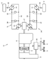
- FIG. 2 is a configuration diagram showing a schematic configuration of the motor grader 1 shown in FIG.
- the pair of left and right front wheels described above has a left front wheel 2 and a right front wheel 3.
- the motor grader 1 includes an engine 6.
- the engine 6 is supported by a rear frame 52 shown in FIG.
- the hydraulic system 7L, 7R is connected to one output side of the engine 6.
- the hydraulic system 7L drives the left front wheel 2.
- the hydraulic system 7R drives the right front wheel 3.
- left rear wheels 4, 5 and left rear wheels 4, 5 and a pair of right rear wheels are connected via a torque converter 8, a transmission 9, a final reduction gear 10 and a tandem device 11. It is connected.
- the engine 6 drives the left rear wheels 4, 5 and the right rear wheel via the torque converter 8, the transmission 9, the final reduction device 10, and the tandem device 11.
- the motor grader 1 is an all-wheel drive vehicle in which the front wheels 2, 3 and the left rear wheels 4, 5 and the right rear wheel are driven together by the power generating and transmitting devices 6-11.
- the devices 6 to 11 constitute an all-wheel drive device 12.
- Most of the all-wheel drive device 12 (the engine 6, a part of the hydraulic systems 7L and 7R, the torque converter 8, the transmission 9, and the final reduction device 10) is supported by the rear frame 52.
- the hydraulic system 7L includes a left hydraulic pump 13 and a left hydraulic motor 14.
- the hydraulic system 7 ⁇ / b> R includes a right hydraulic pump 16 and a right hydraulic motor 15.
- the left hydraulic pump 13 and the right hydraulic pump 16 are driven by the output of the engine 6 being transmitted through a PTO (Power Take-Off) 17.
- the left hydraulic motor 14 is rotated by hydraulic oil discharged from the left hydraulic pump 13 to drive the left front wheel 2.
- the right hydraulic motor 15 is rotated by hydraulic oil discharged from the right hydraulic pump 16 to drive the right front wheel 3.
- the hydraulic motors 14 and 15 are oblique axis type axial motors.
- the left hydraulic pump 13 and the left hydraulic motor 14 are connected by a left hydraulic circuit 18.
- the hydraulic oil discharged from the left hydraulic pump 13 is supplied to the left hydraulic motor 14 via the left hydraulic circuit 18.
- the rotational speed of the left front wheel 2 when the left front wheel 2 is driven is controlled by hydraulic oil discharged from the left hydraulic pump 13.
- the left hydraulic circuit 18 is provided with a relief valve 30 and a flushing valve 32.
- the relief valve 30 is provided in order to prevent the hydraulic pressure in the left hydraulic circuit 18 from increasing excessively.
- the flushing valve 32 is provided for discharging excess oil.
- the right hydraulic pump 16 and the right hydraulic motor 15 are connected by a right hydraulic circuit 19.
- the hydraulic oil discharged from the right hydraulic pump 16 is supplied to the right hydraulic motor 15 via the right hydraulic circuit 19.
- the rotational speed of the right front wheel 3 when the right front wheel 3 is driven is controlled by hydraulic fluid discharged from the right hydraulic pump 16.
- the right hydraulic circuit 19 is provided with a relief valve 31 and a flushing valve 33.
- the relief valve 31 is provided in order to prevent the pressure of the hydraulic oil in the right hydraulic circuit 19 from increasing excessively.
- the flushing valve 33 is provided for discharging excess oil.
- a left hydraulic clutch mechanism 22 is provided between the left front wheel 2 and the left hydraulic motor 14.
- a right hydraulic clutch mechanism 23 is provided between the right front wheel 3 and the right hydraulic motor 15.
- FIG. 3 is a schematic diagram of the power transmission device 125 according to an embodiment of the present invention.
- the power transmission device 125 is a device for transmitting the power of a hydraulic motor 124 (corresponding to the hydraulic motors 14 and 15 shown in FIG. 2) as a drive source to a wheel (corresponding to the front wheels 2 and 3 shown in FIG. 2). is there.
- the power transmission device 125 includes a first planetary gear speed reducer 126, a second planetary gear speed reducer 127, and a hydraulic clutch mechanism 128 (corresponding to the hydraulic clutch mechanisms 22 and 23 shown in FIG. 2).
- the dashed line shown in FIG. 3 has shown the centerline CL used as the rotation center of the rotary body contained in the power transmission device 125.
- FIG. 3 has shown the centerline CL used as the rotation center of the rotary body contained in the power transmission device 125.
- the first planetary gear reducer 126 has a first sun gear 130, a plurality of first planetary gears 131, a first carrier 132, and a first ring gear 133.
- the second planetary gear speed reducer 127 includes a second sun gear 135, a plurality of second planetary gears 136, a second carrier 137, and a second ring gear 138.
- torque from the hydraulic motor 124 is input to the first sun gear 130.
- the first carrier 132 is connected to the second sun gear 135.
- the first ring gear 133 is connected to the second ring gear 138. Both ring gears 133 and 138 are connected to a wheel.
- the second carrier 137 is connected to the fixed housing 139 via the hydraulic clutch mechanism 128.
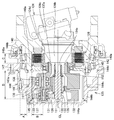
- FIG. 4 is an overall cross-sectional configuration diagram of the power transmission device 125 according to an embodiment of the present invention.
- the hydraulic motor 124 is housed in a motor housing 140 inside the vehicle body (on the right side in FIG. 4).
- the hydraulic motor 124 has a rotatable output shaft 124a and a main body 124b.
- the output shaft 124a protrudes from the body portion 124b toward the outside of the vehicle body (left side in FIG. 4).
- the dashed-dotted line shown in FIG. 4 has shown the centerline CL used as the rotation center of rotating objects, such as the output shaft 124a of the hydraulic motor 124, similarly to FIG.
- the output shaft 124a is disposed coaxially with the rotating shaft of the wheel.
- the motor housing 140 has a protruding portion 140a that protrudes to the outside of the vehicle body.
- the power transmission device 125 has a rotating housing 144.
- a first planetary gear speed reducer 126, a second planetary gear speed reducer 127, and a hydraulic clutch mechanism 128 are housed in the rotating housing 144.
- the first planetary gear speed reducer 126 and the second planetary gear speed reducer 127 are arranged side by side in the axial direction of the output shaft 124a (the direction in which the center line CL extends and in the left-right direction in FIG. 4).
- the rotating housing 144 is provided so as to be rotatable about the center line CL with respect to the motor housing 140.
- the rotating housing 144 has a bowl shape that opens to the motor housing 140 side.
- the rotating housing 144 has a first case portion 144a, a second case portion 144b, a third case portion 144c, and a fourth case portion 144d.
- the first case portion 144a has a substantially disc shape and constitutes a bowl-shaped bottom portion.
- the second case portion 144b, the third case portion 144c, and the fourth case portion 144d have an annular shape, and form a bowl-shaped side portion.
- the first case portion 144a and the second case portion 144b are fixed by bolts 145.
- the second case portion 144b and the third case portion 144c are fixed by bolts 146.
- the third case portion 144c and the fourth case portion 144d are fixed by bolts 147.
- An oil seal 148a and a floating seal 148b are provided between the rotary housing 144 (fourth case portion 144d) and the motor housing 140.
- the oil seal 148a and the floating seal 148b are provided to prevent oil in the rotating housing 144 from leaking to the outside.
- a recess 147a is formed in the third case portion 144c.
- the concave portion 147a is formed such that a part of the outer surface of the third case portion 144c is recessed.
- the head of the bolt 147 is housed in the recess 147a.
- a bolt (not shown) is screwed into the fourth case portion 144d through a hole formed in the third case portion 144c. Wheels (front wheels 2 and 3 shown in FIG. 2) are attached to the rotating housing 144 by the bolts.
- Two wheel bearings 142 and 143 are arranged between the protruding portion 140a of the motor housing 140 and the fourth case portion 144d of the rotating housing 144 in the radial direction.
- the rotating housing 144 and the wheel are rotatably supported by the protrusion 140a of the motor housing 140 via two wheel bearings 142 and 143.
- the wheel bearings 142 and 143 are arranged on the outer side in the radial direction than the protrusion 140 a of the motor housing 140.
- the inner rings of the wheel bearings 142 and 143 are fixed to the outer peripheral surface of the protrusion 140 a of the motor housing 140.
- the outer rings of the wheel bearings 142 and 143 are fixed to the inner peripheral surface of the fourth case portion 144d of the rotary housing 144.
- the input shaft 150 is arranged coaxially with the output shaft 124a of the hydraulic motor 124.
- the input shaft 150 is provided to be rotatable about the center line CL.
- the input shaft 150 is disposed outside the vehicle body with respect to the output shaft 124 a of the hydraulic motor 124.
- the end surface of the output shaft 124a on the outer side of the vehicle body and the end surface of the input shaft 150 on the inner side of the vehicle body are opposed to each other.
- a spline groove is formed on the outer peripheral surface of the output shaft 124a near the outer end of the vehicle body.
- Spline grooves are formed on the outer peripheral surface of the input shaft 150 in the vicinity of the inner end of the vehicle body.
- the output shaft 124 a and the input shaft 150 are connected by a spline cylinder 152.
- Spline teeth are formed on the inner peripheral surface of the spline cylinder 152. The spline teeth are fitted into the spline groove of the output shaft 124a and the spline groove of the input shaft 150, and the input shaft 150 and the output shaft 124a are rotatably connected as a unit.
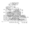
- FIG. 5 is a cross-sectional configuration diagram of the first planetary gear reducer 126 and the second planetary gear reducer 127 of the power transmission device 125 shown in FIG.
- the first planetary gear speed reducer 126 is arranged farther from the hydraulic motor 124 than the second planetary gear speed reducer 127.
- the first planetary gear reducer 126 is arranged on the outer side of the vehicle body with respect to the second planetary gear reducer 127.
- the first planetary gear reducer 126 has a first sun gear 130, a first planetary gear 131, a first carrier 132, and a first ring gear 133.
- the first sun gear 130 is formed integrally with the input shaft 150.
- the first sun gear 130 is formed at the end of the input shaft 150 outside the vehicle body.
- the first sun gear 130 is rotatably provided integrally with the input shaft 150.
- the first sun gear 130 may be connected to the input shaft 150.
- a ball 151 is disposed between the end surface of the input shaft 150 on the outer side of the vehicle body and the rotary housing 144 (first case portion 144a). The ball 151 receives the thrust force of the input shaft 150.
- the plurality of first planetary gears 131 are rotatably supported by the first carrier 132 and mesh with the first sun gear 130.
- the first carrier 132 is formed with a plurality of slits penetrating in the radial direction at predetermined intervals in the circumferential direction. Each first planetary gear 131 is disposed in this slit.
- a first support pin 154 is provided through each slit in the axial direction. Each first planetary gear 131 is rotatably supported by the first support pin 154 via two tapered roller bearings 155.
- a connecting ring 132a is formed on the inner periphery of the first carrier 132 inside the vehicle body so as to protrude in the axial direction.
- a plurality of teeth are formed on the inner peripheral surface of the connecting ring 132a.
- the first ring gear 133 is provided on the inner peripheral surface of the rotary housing 144 (second case portion 144b). A plurality of first planetary gears 131 mesh with the first ring gear 133.
- the second planetary gear reducer 127 is arranged closer to the hydraulic motor 124 than the first planetary gear reducer 126.
- the second planetary gear reducer 127 is disposed on the inner side of the vehicle body with respect to the first planetary gear reducer 126.
- the second planetary gear speed reducer 127 includes a second sun gear 135, a second planetary gear 136, a second carrier 137, and a second ring gear 138.
- a hole 135 a penetrating in the axial direction is formed at the center of the second sun gear 135.
- the input shaft 150 passes through the hole 135a.
- a plurality of teeth are formed on a part of the outside of the vehicle body of the second sun gear 135, and the teeth of the connection ring 132a of the first carrier 132 are engaged with the teeth. Accordingly, the second sun gear 135 is connected to the first carrier 132.
- the plurality of second planetary gears 136 are rotatably supported by the second carrier 137 and mesh with teeth formed on the inner side of the vehicle body of the second sun gear 135. Similar to the first carrier 132, the second carrier 137 has a plurality of slits penetrating in the radial direction at predetermined intervals in the circumferential direction. Each second planetary gear 136 is disposed in the slit. A second support pin 162 is provided through each slit in the axial direction. Each second planetary gear 136 is rotatably disposed on the second support pin 162 via two tapered roller bearings 163. A connecting ring 137a protruding in the axial direction is formed at the outer peripheral end of the side surface of the second carrier 137 on the inner side of the vehicle body.
- the second ring gear 138 is provided on the inner peripheral surface of the rotary housing 144 (second case portion 144b). A plurality of second planetary gears 136 mesh with the second ring gear 138.
- the first ring gear 133 and the second ring gear 138 are formed at the same position in the radial direction.
- the first ring gear 133 and the second ring gear 138 have the same diameter.
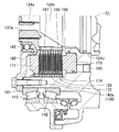
- FIG. 6 is a cross-sectional configuration diagram of the hydraulic clutch mechanism 128 of the power transmission device 125 shown in FIG.
- the hydraulic clutch mechanism 128 is a mechanism that prohibits rotation (power transmission) of the second carrier 137 around the center line CL in the on state and permits rotation (transmission cancellation) of the second carrier 137 in the off state. .
- the hydraulic clutch mechanism 128 includes a rotating part and a fixed part.
- the rotating portion has a clutch input portion 167 and a plurality (9 in this example) of clutch plates 168.
- the clutch input unit 167 is connected to a connection ring 137 a formed in a part of the second carrier 137, and is rotatably provided with the second carrier 137.
- the plurality of clutch plates 168 are formed in a ring shape.
- An engaging portion 169 is formed on the outer peripheral surface of the clutch input portion 167.
- An engaging portion that engages with the engaging portion 169 is formed on the inner peripheral surface of the clutch plate 168.
- Friction facing is affixed to both surfaces of the clutch plate 168.
- the clutch plate 168 rotates together with the second carrier 137 and can move in the axial direction along the engaging portion 169 of the clutch input portion 167.
- the fixing portion of the hydraulic clutch mechanism 128 has a pressure plate 171, a plurality (10 in this example) of fixing plates 172, and a piston 173.
- the fixed portion is attached to the motor housing 140 so as not to rotate.
- the plurality of fixing plates 172 are formed in a ring shape.
- An engaging portion 174 is formed on the inner peripheral surface of the protruding portion 140 a of the motor housing 140.
- An engaging portion that engages with the engaging portion 174 is formed on the outer periphery of the fixed plate 172.
- the fixed plate 172 is mounted so as not to rotate relative to the motor housing 140 and to be movable in the axial direction.
- the protrusion 140a of the motor housing 140 has a function as the fixed housing 139 shown in FIG.
- a hydraulic clutch mechanism 128 is disposed on the radially inner side with respect to the protruding portion 140a of the motor housing 140.
- the wheel bearings 142 and 143 described above are arranged on the outer side in the radial direction with respect to the protruding portion 140a of the motor housing 140. As a result, the hydraulic clutch mechanism 128 is disposed radially inward of the wheel bearings 142 and 143.
- the hydraulic clutch mechanism 128 is disposed on the radially outer side with respect to the clutch input portion 167.
- a portion where the hydraulic clutch mechanism 128 is mounted has a substantially cylindrical shape, and an inner peripheral surface thereof faces the main body portion 124b of the hydraulic motor 124.
- the hydraulic clutch mechanism 128 is disposed on the outer side in the radial direction than the main body portion 124 b of the hydraulic motor 124.
- An annular plate portion 180 is fixed to the front end of the protrusion 140a of the motor housing 140 on the outer side of the vehicle body by a bolt 181.
- the annular plate portion 180 is fixed to the protruding portion 140a of the motor housing 140 in the vicinity of the outer peripheral edge thereof.
- the inner peripheral edge of the annular plate portion 180 is formed in a cylindrical shape.
- a ball bearing 182 is provided between the inner peripheral edge of the annular plate portion 180 and the clutch input portion 167.
- the pressure plate 171 is formed in a ring shape.
- the pressure plate 171 is disposed between the protruding portion 140a of the motor housing 140 and the inner peripheral edge of the annular plate portion 180 in the radial direction.
- An engaging portion that engages with the engaging portion 174 is formed on the outer periphery of the pressure plate 171.
- a snap ring that restricts the movement of the pressure plate 171 toward the outside of the vehicle body is provided on the outside of the vehicle body with respect to the pressure plate 171.
- the clutch plates 168 and the fixed plates 172 are alternately arranged in the axial direction along the center line CL.
- a piston 173 is arranged inside the vehicle body and a pressure plate 171 is arranged outside the vehicle body with respect to the assembly in which the clutch plates 168 and the fixed plates 172 are alternately stacked.
- the clutch plate 168 and the fixed plate 172 are configured to be in pressure contact between the piston 173 and the pressure plate 171.
- the clutch 173 is switched on and off by operating the piston 173.
- the clutch is on (brake on)
- the rotating portion of the hydraulic clutch mechanism 128 is fixed and prohibited from rotating.
- the rotating portion of the hydraulic clutch mechanism 128 is released from the fixed state and allowed to rotate.
- the piston 173 is operated by hydraulic pressure supplied from a control valve (not shown).
- a supply port 185 for supplying hydraulic pressure is formed in the motor housing 140 as shown in FIG.
- the supply port 185 is formed in the middle portion in the radial direction of the motor housing 140 along the axial direction.
- the supply port 185 communicates the outside (for example, a motor housing space in which the hydraulic motor 124 is housed) and a chamber in which the piston 173 is disposed.
- the hydraulic pressure supplied from the control valve to the supply port 185 acts on the piston 173.
- Torque is input from the hydraulic motor 124 to the first sun gear 130 via the input shaft 150. Torque input to the first sun gear 130 is transmitted to the first ring gear 133 via the plurality of first planetary gears 131. The torque from the first carrier 132 is input to the second sun gear 135. Torque input to the second sun gear 135 is transmitted to the second ring gear 138 via the plurality of second planetary gears 136. The torque transmitted to the second ring gear 138 is combined with the torque of the first ring gear 133 and transmitted to the wheel. The reaction force of the torque of the second carrier 137 is received by the fixed housing 139 via the hydraulic clutch mechanism 128.
- the torque input from the hydraulic motor 124 and transmitted by the first planetary gear speed reducer 126 and the torque transmitted by the second planetary gear speed reducer 127 are combined to form a wheel. Is transmitted to.
- the hydraulic clutch mechanism 128 is turned off by stopping the hydraulic pressure supply to the piston 173 and discharging the pressure oil.
- the hydraulic clutch mechanism 128 is off (brake off)
- the rotation of the second carrier 137 of the second planetary gear speed reducer 127 is allowed. Therefore, even when torque is input from the hydraulic motor 124, the second carrier 137 rotates, and the second planetary gear 136 rotates and revolves. Therefore, torque is not transmitted to the wheel from either the first planetary gear reducer 126 or the second planetary gear reducer 127.
- the hydraulic clutch mechanism 128 on the side where the supply port 185 is illustrated below the center line CL is supplied with hydraulic pressure to the piston 173. Not in off state.
- the hydraulic clutch mechanism 128 above the center line CL and on the side where the supply port 185 is not shown is ON when hydraulic pressure is supplied to the piston 173. State.
- FIG. 7 is a side view showing a schematic configuration of the hydraulic motor 124.
- the hydraulic motor 124 has an output shaft 124a, a main body portion 124b, and a cylinder housing portion 124c.
- the output shaft 124a protrudes from the main body 124b to the outside of the vehicle body.
- the output shaft 124a is connected to a drive shaft housed in the main body portion 124b and supported by the main body portion 124b. At least a part of the cylinder block that is rotatably provided with the drive shaft is accommodated in the cylinder accommodating portion 124c.
- the cylinder block is inclined with respect to the drive shaft.
- the main body 124b has an axisymmetric shape that is symmetric with respect to the center line CL.
- the main body portion 124b has a maximum outer diameter portion 124d having the maximum outer diameter. In the axial direction along the center line CL, the maximum outer diameter portion 124d is provided at the end of the main body portion 124b on the side connected to the cylinder housing portion 124c.
- the power transmission device 125 includes a hydraulic motor 124, a motor housing 140, a rotating housing 144, and wheel bearings 142 and 143.
- the hydraulic motor 124 has a rotatable output shaft 124a.
- the motor housing 140 accommodates the hydraulic motor 124.
- the rotation housing 144 is rotatable with respect to the motor housing 140 around a center line CL that indicates the rotation center of the output shaft 124 a of the hydraulic motor 124.
- the wheel bearings 142 and 143 support the rotary housing 144 so as to be rotatable with respect to the motor housing 140.
- the power transmission device 125 further includes a first planetary gear reducer 126, a second planetary gear reducer 127, and a hydraulic clutch mechanism 128.
- the second planetary gear speed reducer 127 includes a second sun gear 135, a second planetary gear 136 that meshes with the second sun gear 135, and a second planetary gear 136 that rotatably supports the second planetary gear 136.
- a carrier 137 a carrier 137.
- the hydraulic clutch mechanism 128 allows or prohibits the rotation of the second carrier 137 around the center line CL.
- the hydraulic clutch mechanism 128 is disposed radially inward of the wheel bearings 142 and 143.
- a region B indicates a range where the hydraulic clutch mechanism 128 is disposed in the radial direction.
- the region A is farther from the center line CL than the region B.
- the shortest distance from the center line CL is smaller than the region A.
- fixing plates 172 can be attached to the protrusion 140a. It is not necessary to provide a clutch housing separate from the motor housing 140 and mount the fixing plate 172, and the clutch housing can be dispensed with.
- the power transmission device 125 of the present embodiment has a simple structure that does not include a clutch housing, the configuration of the clutch can be simplified and the productivity can be improved.
- the wheel bearings 142 and 143 are provided on the radially outer side of the projecting portion 140 a of the motor housing 140, and the saddle-shaped rotary housing 144 surrounds the hydraulic clutch mechanism 128.
- the wheel bearings 142 and 143 are disposed radially outside the hydraulic clutch mechanism 128, and the diameters of the wheel bearings 142 and 143 are increased. Thereby, since the rigidity of the wheel bearings 142 and 143 can be improved, it is possible to suppress deformation of the rotating housing 144 when a load is applied to the rotating housing 144. Since the rotating housing 144 can be supported more stably, the reliability of the first planetary gear reducer 126 and the second planetary gear reducer 127 accommodated in the rotating housing 144 can be improved. In addition, the service life of the wheel bearings 142 and 143 can be extended.
- the first planetary gear speed reducer 126 and the hydraulic clutch mechanism 128 are disposed so as to overlap each other when viewed from the axial direction of the output shaft 124 a along the center line CL.
- Part of the first planetary gear 131, the first carrier 132 and the first ring gear 133 constituting the first planetary gear speed reducer 126 is a region B indicating a range where the hydraulic clutch mechanism 128 is disposed in the radial direction. Is placed inside.
- the wheel bearings 142 and 143 are not superimposed on any of the first planetary gear speed reducer 126 and the second planetary gear speed reducer 127 when viewed in the axial direction along the center line CL.
- the wheel bearings 142 and 143 are disposed on the radially outer side than the first planetary gear speed reducer 126 and the second planetary gear speed reducer 127.
- the first planetary gear speed reducer 126 and the second planetary gear speed reducer 127 are arranged out of the region A in FIG. 1 showing the range in which the wheel bearings 142 and 143 are arranged in the radial direction.
- the hydraulic motor 124 includes an output shaft 124a and a main body portion 124b that supports the output shaft 124a.
- the hydraulic clutch mechanism 128 is disposed so as to surround the main body 124b.
- the main body 124b of the hydraulic motor 124, the hydraulic clutch mechanism 128, and the wheel bearings 142 and 143 are arranged so as to overlap in the axial direction along the center line CL, and the main body 124b and the hydraulic type are arranged radially outward from the center line CL.
- the clutch mechanism 128 and the wheel bearings 142 and 143 are arranged in this order.
- the hydraulic clutch mechanism 128 is disposed between the main body portion 124 b of the hydraulic motor 124 and the wheel bearings 142 and 143.
- positioned radially inside rather than the wheel bearings 142 and 143 is realizable more reliably.
- the main body 124b of the hydraulic motor 124 has a symmetrical shape with respect to the center line CL.
- the main body portion 124b has a maximum outer diameter portion 124d having the maximum outer diameter.
- the inner diameter of the hydraulic clutch mechanism 128 is smaller than the outer diameter of the maximum outer diameter portion 124d.
- the outer peripheral surface of the maximum outer diameter portion 124d is disposed in a region B shown in FIG. A configuration in which the hydraulic clutch mechanism 128 is disposed closer to the inner side in the radial direction than the wheel bearings 142 and 143 by disposing the hydraulic clutch mechanism 128 closer to the hydraulic motor 124 and making the inner diameter of the hydraulic clutch mechanism 128 smaller. Can be realized more reliably.
- the hydraulic clutch mechanism 128 has a clutch plate 168 and a fixed plate 172.
- the clutch plates 168 and the fixed plates 172 are alternately arranged in the axial direction along the center line CL.
- the fixed plate 172 is attached to the protrusion 140 a of the motor housing 140.
- the power transmission device 125 further includes an input shaft 150.
- the input shaft 150 is connected to the output shaft 124 a of the hydraulic motor 124, and inputs the torque from the hydraulic motor 124 to the first sun gear 130.
- the hydraulic clutch mechanism 128 is disposed on the hydraulic motor 124 side with respect to the input shaft 150.
- the input shaft 150 may be integrated with the first sun gear 130. Alternatively, the input shaft 150 may be connected to the first sun gear 130.
- a region D indicates a range where the input shaft 150 is arranged in the axial direction.
- An output shaft 124a of the hydraulic motor 124 is disposed inside the vehicle body in the region D (on the right side in FIG. 4), and the output shaft 124a protrudes from the main body portion 124b to the outside of the vehicle body.
- the hydraulic clutch mechanism 128 is disposed so as to surround the main body 124 b of the hydraulic motor 124. Therefore, the hydraulic clutch mechanism 128 is disposed on the hydraulic motor 124 side with respect to the input shaft 150.
- the outer dimension of the power transmission device 125 in the axial direction along the center line CL can be reduced.
- the hydraulic clutch mechanism 128 does not interfere with the first and second planetary gear speed reducers 126 and 127 provided on the outer periphery of the input shaft 150. Therefore, the first ring gear 133 and the second ring gear 138 are formed to have the same diameter, and the outer diameter of the overall configuration of the first and second planetary gear speed reducers 126 and 127 is reduced, thereby reducing the weight of the power transmission device 125. It becomes possible.
- the motor grader 1 includes a left front wheel 2 and a right front wheel 3 as shown in FIGS.
- the motor grader 1 also includes a power transmission device 125 shown in FIG. 4 that transmits power to the left front wheel 2 and the right front wheel 3. In this way, the weight of the left front wheel 2 and the right front wheel 3 of the motor grader 1 can be reduced.
Landscapes
- Engineering & Computer Science (AREA)
- Mechanical Engineering (AREA)
- General Engineering & Computer Science (AREA)
- Chemical & Material Sciences (AREA)
- Combustion & Propulsion (AREA)
- Transportation (AREA)
- Mining & Mineral Resources (AREA)
- Civil Engineering (AREA)
- Structural Engineering (AREA)
- Retarders (AREA)
- Hydraulic Clutches, Magnetic Clutches, Fluid Clutches, And Fluid Joints (AREA)
- Structure Of Transmissions (AREA)
- Arrangement Of Transmissions (AREA)
Abstract
小型化および軽量化が可能な動力伝達装置を提供する。油圧モータ(124)は、回転可能な出力軸(124a)を有している。ホイールベアリング(142,143)は、回転ハウジング(144)をモータハウジング(140)に対し回転可能に支持している。油圧式クラッチ機構(128)は、第2遊星歯車減速機(127)の第2キャリヤ(137)の、出力軸(124a)の回転中心を中心とする回転を許容または禁止する。油圧式クラッチ機構(128)は、ホイールベアリング(142,143)よりも径方向内側に配置されている。
Description
本発明は、動力伝達装置と、その動力伝達装置を備えるモータグレーダとに関する。
近年のモータグレーダなどには、前後輪の全てを駆動する全輪駆動装置を設けることがある。全輪駆動装置は、エンジンの出力を変速機を介して後輪に伝達して後輪を駆動するとともに、エンジンの出力を油圧ポンプに伝達し、この油圧ポンプからの吐出油で回転する一対の油圧モータで左右の前輪をそれぞれ駆動している。
特開2011-106611号公報(特許文献1)には、油圧モータと、第1遊星歯車減速機と、第2遊星歯車減速機とを有し、油圧モータのトルクを2段の遊星歯車減速機を介してホイールに伝達する動力伝達装置において、第2遊星歯車減速機のキャリヤに油圧式クラッチ機構を連結して当該キャリヤの回転を禁止または許容する構成が開示されている。
特許文献1記載の装置では、油圧式クラッチ機構の径が大きく、装置の小型化および軽量化が困難であった。
本発明の目的は、小型化および軽量化が可能な動力伝達装置と、その動力伝達装置を備えるモータグレーダとを提供することである。
本発明に係る動力伝達装置は、油圧モータと、モータハウジングと、回転ハウジングと、ベアリングと、第1遊星歯車減速機と、第2遊星歯車減速機と、クラッチとを備えている。油圧モータは、回転可能な出力軸を有している。モータハウジングは、油圧モータを収容している。回転ハウジングは、モータハウジングに対し出力軸の回転中心を中心として回転可能である。ベアリングは、回転ハウジングをモータハウジングに対し回転可能に支持している。第1遊星歯車減速機は、油圧モータからトルクが入力される第1太陽ギヤと、第1太陽ギヤに噛み合う複数の第1遊星ギヤと、複数の第1遊星ギヤを回転自在に支持する第1キャリヤと、回転ハウジングに設けられ、複数の第1遊星ギヤが噛み合う第1リングギヤとを有している。第2遊星歯車減速機は、第1キャリヤに連結される第2太陽ギヤと、第2太陽ギヤに噛み合う複数の第2遊星ギヤと、複数の第2遊星ギヤを回転自在に支持する第2キャリヤと、回転ハウジングに設けられ、複数の第2遊星ギヤが噛み合う第2リングギヤとを有している。クラッチは、出力軸の回転中心を中心とする第2キャリヤの回転を許容または禁止する。クラッチは、ベアリングよりも径方向内側に配置されている。
本発明の動力伝達装置によれば、クラッチの径を小さくできるので、径方向における動力伝達装置の外形寸法を小さくすることができる。
上記動力伝達装置において、出力軸の軸方向より見て、第1遊星歯車減速機とクラッチとが重畳して配置されている。このように第1遊星歯車減速機に対するクラッチの位置を規定することにより、クラッチがベアリングよりも径方向内側に配置された構成を確実に実現することができる。
上記動力伝達装置において、油圧モータは、出力軸を支持する本体部を有している。クラッチは、油圧モータの本体部を取り囲んで配置されている。径方向において、油圧モータの本体部とベアリングとの間にクラッチを配置することにより、クラッチがベアリングよりも径方向内側に配置された構成を、より確実に実現することができる。
上記動力伝達装置において、本体部は、出力軸の回転中心に対して対称な形状を有している。本体部の最大径よりもクラッチの内径が小さい。クラッチを油圧モータにより近づけて配置し、クラッチの内径をより小さくすることにより、クラッチがベアリングよりも径方向内側に配置された構成を確実に実現することができる。
上記動力伝達装置において、クラッチは、出力軸の軸方向に交互に配置されたクラッチプレートと固定プレートとを有している。固定プレートは、モータハウジングに装着されている。これにより、動力伝達装置はクラッチハウジングを必要としないシンプルな構成になるので、動力伝達装置の小型化および軽量化を確実に実現することができる。
上記動力伝達装置は、入力軸をさらに備えている。入力軸は、油圧モータに連結されており、油圧モータからのトルクを第1太陽ギヤに入力する。出力軸の軸方向において、クラッチは、入力軸に対して油圧モータ側に配置されている。このように入力軸に対するクラッチの位置を規定することにより、第1および第2遊星歯車減速機にクラッチが干渉することがない。そのため、第1および第2遊星歯車減速機の全体構成の外径を小さくして、動力伝達装置を軽量化することが可能になる。
本発明に係るモータグレーダは、前輪と、前輪に動力を伝達する、上記のいずれかの動力伝達装置とを備えている。このようにすれば、モータグレーダの前輪の重量を低減することができる。
本発明の動力伝達装置は、小型化および軽量化を達成することができる。
以下、本発明の実施形態について図に基づいて説明する。
まず、本発明の思想を適用可能な作業車両の一例として、モータグレーダの構成について説明するが、本発明は、駆動のオンおよびオフを切り換え可能に構成された動力伝達装置を有する、他の各種の作業車両に適用可能である。
まず、本発明の思想を適用可能な作業車両の一例として、モータグレーダの構成について説明するが、本発明は、駆動のオンおよびオフを切り換え可能に構成された動力伝達装置を有する、他の各種の作業車両に適用可能である。
図1は、本発明の一実施形態におけるモータグレーダ1の構成を概略的に示す側面図である。図1に示すように、本実施形態のモータグレーダ1は、全6輪の車両である。モータグレーダ1は、左右一対の前輪と、片側2輪ずつの後輪とからなる走行輪を備えている。前輪は、左前輪2と、図1には図示しない右前輪とを有している。後輪は、左後前輪4と、左後後輪5と、図1には図示しない右後前輪および右後後輪とを有している。前輪および後輪の数および配置は、図1に示す例に限られるものではない。
モータグレーダ1は、ブレード50を備えている。ブレード50は、前輪と後輪との間に設けられている。モータグレーダ1は、ブレード50で、地面の整地作業、除雪作業、軽切削、材料混合などの作業を行なうことができる。
モータグレーダ1は、車体フレームを備えている。車体フレームは、フロントフレーム51と、リヤフレーム52とを有している。フロントフレーム51は、リヤフレーム52に、回動可能に連結されている。
前輪は、ブレード50と共に、フロントフレーム51に設けられている。前輪は、フロントフレーム51の前端部に、回転可能に取り付けられている。後輪は、リヤフレーム52に設けられている。後輪は、リヤフレーム52に、後述するようにエンジンからの駆動力によって回転駆動可能に取り付けられている。
図2は、図1に示すモータグレーダ1の概略構成を示す構成図である。上述した左右一対の前輪は、左前輪2と、右前輪3とを有している。モータグレーダ1は、エンジン6を備えている。エンジン6は、図1に示すリヤフレーム52に支持されている。
エンジン6の一方の出力側には、油圧システム7L,7Rが接続されている。油圧システム7Lは、左前輪2を駆動する。油圧システム7Rは、右前輪3を駆動する。エンジン6の他方の出力側には、トルクコンバータ8、変速機9、終減速装置10およびタンデム装置11を介して、左後輪4,5および左後輪4,5と一対の右後輪が接続されている。エンジン6は、トルクコンバータ8、変速機9、終減速装置10およびタンデム装置11を介して、左後輪4,5と右後輪とを駆動する。
モータグレーダ1は、前輪2,3と左後輪4,5および右後輪とが動力発生用および伝達用の各装置6~11で共に駆動される、全輪駆動車両である。当該装置6~11は、全輪駆動装置12を構成している。全輪駆動装置12のほとんど(エンジン6、油圧システム7L,7Rの一部、トルクコンバータ8、変速機9および終減速装置10)は、リヤフレーム52で支持されている。
油圧システム7Lは、左油圧ポンプ13と、左油圧モータ14とを備えている。油圧システム7Rは、右油圧ポンプ16と、右油圧モータ15とを備えている。左油圧ポンプ13および右油圧ポンプ16は、エンジン6の出力がPTO(Power Take-Off)17を介して伝達されて駆動される。左油圧モータ14は、左油圧ポンプ13から吐出する作動油で回転されて、左前輪2を駆動する。右油圧モータ15は、右油圧ポンプ16から吐出する作動油で回転されて、右前輪3を駆動する。油圧モータ14,15は、本実施形態では、斜軸式アキシャル形のモータである。
左油圧ポンプ13と、左油圧モータ14とは、左油圧回路18により接続されている。左油圧ポンプ13から吐出する作動油は、左油圧回路18を経由して、左油圧モータ14に供給される。左前輪2が駆動されるときの左前輪2の回転速度は、左油圧ポンプ13から吐出する作動油によって、制御されている。
左油圧回路18には、リリーフバルブ30と、フラッシングバルブ32とが設けられている。リリーフバルブ30は、左油圧回路18内の作動油の圧力が過剰に増加するのを防止するために設けられている。フラッシングバルブ32は、余剰油を排出するために設けられている。
右油圧ポンプ16と、右油圧モータ15とは、右油圧回路19により接続されている。右油圧ポンプ16から吐出する作動油は、右油圧回路19を経由して、右油圧モータ15に供給される。右前輪3が駆動されるときの右前輪3の回転速度は、右油圧ポンプ16から吐出する作動油によって、制御されている。
右油圧回路19には、リリーフバルブ31と、フラッシングバルブ33とが設けられている。リリーフバルブ31は、右油圧回路19内の作動油の圧力が過剰に増加するのを防止するために設けられている。フラッシングバルブ33は、余剰油を排出するために設けられている。
左油圧式クラッチ機構22が、左前輪2と左油圧モータ14との間に設けられている。右油圧式クラッチ機構23が、右前輪3と右油圧モータ15との間に設けられている。左油圧式クラッチ機構22および右油圧式クラッチ機構23に油圧が供給されることにより、左前輪2と右前輪3とに動力が伝達されて、モータグレーダ1は全輪駆動となる。左油圧式クラッチ機構22および右油圧式クラッチ機構23への油圧の供給が遮断されると、モータグレーダ1は、全輪駆動が解除されて後輪駆動となる。
図3は、本発明の一実施形態における動力伝達装置125の模式図である。動力伝達装置125は、駆動源としての油圧モータ124(図2に示す油圧モータ14,15に相当)の動力を、ホイール(図2に示す前輪2,3に相当)に伝達するための装置である。動力伝達装置125は、第1遊星歯車減速機126と、第2遊星歯車減速機127と、油圧式クラッチ機構128(図2に示す油圧式クラッチ機構22,23に相当)とを備えている。図3に示す一点鎖線は、動力伝達装置125に含まれる回転物の回転中心となる中心線CLを示している。
第1遊星歯車減速機126は、第1太陽ギヤ130、複数の第1遊星ギヤ131、第1キャリヤ132、および第1リングギヤ133を有している。第2遊星歯車減速機127は、第2太陽ギヤ135、複数の第2遊星ギヤ136、第2キャリヤ137、および第2リングギヤ138を有している。
この動力伝達装置125では、油圧モータ124からのトルクは第1太陽ギヤ130に入力される。第1キャリヤ132は、第2太陽ギヤ135に連結されている。第1リングギヤ133は、第2リングギヤ138に連結されている。両リングギヤ133,138は、ホイールに連結されている。第2キャリヤ137は、油圧式クラッチ機構128を介して、固定ハウジング139に連結されている。
図4は、本発明の一実施形態における動力伝達装置125の全体断面構成図である。図4に示すように、油圧モータ124は、車体内側(図4において右側)のモータハウジング140に収納されている。油圧モータ124は、回転可能な出力軸124aと、本体部124bとを有している。出力軸124aは、本体部124bから、車体外側(図4において左側)に向けて突き出している。図4に示す一点鎖線は、図3と同様に、油圧モータ124の出力軸124aなどの回転物の回転中心となる中心線CLを示している。出力軸124aは、ホイールの回転軸と同軸に配置されている。モータハウジング140は、車体外側に突出する突出部140aを有している。
動力伝達装置125は、回転ハウジング144を有している。回転ハウジング144内に、第1遊星歯車減速機126、第2遊星歯車減速機127、および油圧式クラッチ機構128が収納されている。第1遊星歯車減速機126と第2遊星歯車減速機127とは、出力軸124aの軸方向(中心線CLの延びる方向であって、図4における左右方向)に並んで配置されている。回転ハウジング144は、モータハウジング140に対し、中心線CLを中心として回転可能に設けられている。回転ハウジング144は、モータハウジング140側に開く椀型の形状を有している。
回転ハウジング144は、第1ケース部144aと、第2ケース部144bと、第3ケース部144cと、第4ケース部144dとを有している。第1ケース部144aは、略円板状の形状を有しており、椀型の底部を構成している。第2ケース部144b、第3ケース部144cおよび第4ケース部144dは、環状の形状を有しており、椀型の側部を構成している。
第1ケース部144aと第2ケース部144bとは、ボルト145によって固定されている。第2ケース部144bと第3ケース部144cとは、ボルト146によって固定されている。第3ケース部144cと第4ケース部144dとは、ボルト147によって固定されている。
回転ハウジング144(第4ケース部144d)とモータハウジング140との間に、オイルシール148aおよびフローティングシール148bが設けられている。オイルシール148aとフローティングシール148bとは、回転ハウジング144内のオイルが外部に漏れるのを防止するために設けられている。
第3ケース部144cには、凹部147aが形成されている。凹部147aは、第3ケース部144cの外表面の一部が窪んで形成されている。ボルト147の頭部は、凹部147a内に収容されている。
図示しないボルトが第3ケース部144cに形成された穴を介して第4ケース部144dにねじ込まれている。このボルトによってホイール(図2に示す前輪2,3)が回転ハウジング144に取り付けられている。
径方向においてモータハウジング140の突出部140aと回転ハウジング144の第4ケース部144dとの間に、2つのホイールベアリング142,143が配置されている。回転ハウジング144およびホイールは、2つのホイールベアリング142,143を介して、モータハウジング140の突出部140aに回転可能に支持されている。
ホイールベアリング142,143は、モータハウジング140の突出部140aよりも径方向外側に配置されている。ホイールベアリング142,143の内輪は、モータハウジング140の突出部140aの外周面に固定されている。ホイールベアリング142,143の外輪は、回転ハウジング144の第4ケース部144dの内周面に固定されている。
油圧モータ124の出力軸124aと同軸に、入力軸150が配置されている。入力軸150は、中心線CLを中心として回転可能に設けられている。入力軸150は、油圧モータ124の出力軸124aに対して、車体外側に配置されている。出力軸124aの車体外側の端面と、入力軸150の車体内側の端面とは、互いに対向している。
出力軸124aの車体外側の端部付近における外周面に、スプライン溝が形成されている。入力軸150の車体内側の端部付近における外周面に、スプライン溝が形成されている。出力軸124aと入力軸150とは、スプライン筒152によって連結されている。スプライン筒152の内周面には、スプライン歯が形成されている。このスプライン歯が出力軸124aのスプライン溝および入力軸150のスプライン溝に嵌め合わされて、入力軸150と出力軸124aとは一体として回転可能に連結されている。
図5は、図4に示す動力伝達装置125の、第1遊星歯車減速機126および第2遊星歯車減速機127の断面構成図である。図4およびその部分拡大図である図5に示すように、第1遊星歯車減速機126は、第2遊星歯車減速機127よりも油圧モータ124から離れて配置されている。第1遊星歯車減速機126は、第2遊星歯車減速機127に対して車体外側に配置されている。第1遊星歯車減速機126は、第1太陽ギヤ130と、第1遊星ギヤ131と、第1キャリヤ132と、第1リングギヤ133とを有している。
第1太陽ギヤ130は、入力軸150と一体に形成されている。第1太陽ギヤ130は、入力軸150の車体外側の端部に形成されている。第1太陽ギヤ130は、入力軸150と一体として回転可能に設けられている。第1太陽ギヤ130は、入力軸150に連結されていてもよい。入力軸150の車体外側の端面と、回転ハウジング144(第1ケース部144a)との間には、ボール151が配置されている。ボール151は、入力軸150のスラスト力を受け止めている。
複数の第1遊星ギヤ131は、それぞれ第1キャリヤ132に回転自在に支持され、第1太陽ギヤ130と噛み合っている。第1キャリヤ132には、円周方向に所定の間隔で径方向に貫通する複数のスリットが形成されている。このスリットに各第1遊星ギヤ131が配置されている。各スリットを軸方向に貫通して、第1支持ピン154が設けられている。各第1遊星ギヤ131は、第1支持ピン154に、2つのテーパローラベアリング155を介して回転自在に支持されている。第1キャリヤ132の車体内側の内周部には、軸方向に突出して連結リング132aが形成されている。連結リング132aの内周面には、複数の歯が形成されている。
第1リングギヤ133は、回転ハウジング144(第2ケース部144b)の内周面に設けられている。第1リングギヤ133には、複数の第1遊星ギヤ131が噛み合っている。
第2遊星歯車減速機127は、第1遊星歯車減速機126よりも油圧モータ124側に配置されている。第2遊星歯車減速機127は、第1遊星歯車減速機126に対して車体内側に配置されている。第2遊星歯車減速機127は、第2太陽ギヤ135と、第2遊星ギヤ136と、第2キャリヤ137と、第2リングギヤ138とを有している。
第2太陽ギヤ135の中心部に、軸方向に貫通する孔135aが形成されている。この孔135aを入力軸150が貫通している。第2太陽ギヤ135の車体外側の一部には複数の歯が形成されており、この歯に第1キャリヤ132の連結リング132aの複数の歯が噛み合っている。これにより第2太陽ギヤ135は、第1キャリヤ132に連結されている。
複数の第2遊星ギヤ136は、それぞれ第2キャリヤ137に回転自在に支持され、第2太陽ギヤ135の車体内側の部分に形成された歯に噛み合っている。第2キャリヤ137には、第1キャリヤ132と同様に、円周方向に所定の間隔で径方向に貫通する複数のスリットが形成されている。このスリットに各第2遊星ギヤ136が配置されている。各スリットを軸方向に貫通して、第2支持ピン162が設けられている。各第2遊星ギヤ136は、第2支持ピン162に、2つのテーパローラベアリング163を介して回転自在に配置されている。第2キャリヤ137の車体内側の側面外周端部には、軸方向に突出する連結リング137aが形成されている。
第2リングギヤ138は、回転ハウジング144(第2ケース部144b)の内周面に設けられている。第2リングギヤ138には、複数の第2遊星ギヤ136が噛み合っている。第1リングギヤ133と第2リングギヤ138とは、径方向において同じ位置に形成されている。第1リングギヤ133と第2リングギヤ138とは、相等しい径を有している。
図6は、図4に示す動力伝達装置125の、油圧式クラッチ機構128の断面構成図である。油圧式クラッチ機構128は、オン状態で中心線CLを中心とする第2キャリヤ137の回転を禁止(動力伝達)し、オフ状態で第2キャリヤ137の回転を許容(伝達解除)する機構である。
図4およびその部分拡大図である図6に示すように、油圧式クラッチ機構128は、回転部と固定部とから構成されている。回転部は、クラッチ入力部167と、複数(この例では9枚)のクラッチプレート168とを有している。クラッチ入力部167は、第2キャリヤ137の一部に形成された連結リング137aに連結されており、第2キャリヤ137とともに回転可能に設けられている。
複数のクラッチプレート168は、リング状に形成されている。クラッチ入力部167の外周面には、係合部169が形成されている。クラッチプレート168の内周面には、係合部169に係合する係合部が形成されている。クラッチプレート168の両面には、摩擦フェーシングが貼付されている。クラッチプレート168は、第2キャリヤ137とともに回転するとともに、クラッチ入力部167の係合部169に沿って軸方向に移動が可能である。
油圧式クラッチ機構128の固定部は、プレッシャプレート171と、複数(この例では10枚)の固定プレート172と、ピストン173とを有している。固定部は、モータハウジング140に対して回転不能に取り付けられている。
複数の固定プレート172は、リング状に形成されている。モータハウジング140の突出部140aの内周面には、係合部174が形成されている。固定プレート172の外周には、係合部174に係合する係合部が形成されている。これにより、固定プレート172は、モータハウジング140に対して相対回転不能でかつ軸方向移動可能に装着されている。モータハウジング140の突出部140aは、図3に示す固定ハウジング139としての機能を有している。
モータハウジング140の突出部140aに対して径方向内側に、油圧式クラッチ機構128が配置されている。モータハウジング140の突出部140aに対して径方向外側に、上述したホイールベアリング142,143が配置されている。これにより油圧式クラッチ機構128は、ホイールベアリング142,143よりも径方向内側に配置されている。
油圧式クラッチ機構128は、クラッチ入力部167に対して径方向外側に配置されている。クラッチ入力部167において、油圧式クラッチ機構128が装着される部分は略円筒状の形状を有しており、その内周面は油圧モータ124の本体部124bに対向している。油圧式クラッチ機構128は、油圧モータ124の本体部124bよりも径方向外側に配置されている。
モータハウジング140の突出部140aの車体外側の先端に、環状板部180が、ボルト181によって固定されている。環状板部180は、その外周縁の近傍において、モータハウジング140の突出部140aに固定されている。環状板部180の内周縁は、円筒形状に形成されている。環状板部180の内周縁と、クラッチ入力部167との間に、ボールベアリング182が設けられている。
プレッシャプレート171は、リング状に形成されている。プレッシャプレート171は、径方向において、モータハウジング140の突出部140aと環状板部180の内周縁との間に配置されている。プレッシャプレート171の外周には、係合部174に係合する係合部が形成されている。プレッシャプレート171に対し車体外側には、プレッシャプレート171の車体外側向きの移動を規制するスナップリングが設けられている。
クラッチプレート168と固定プレート172とは、中心線CLに沿う軸方向に交互に配置されている。クラッチプレート168と固定プレート172とが交互に重ねられた組立体に対し、車体内側にピストン173が配置されており、車体外側にプレッシャプレート171が配置されている。クラッチプレート168と固定プレート172とは、ピストン173とプレッシャプレート171との間で圧接されるように構成されている。
油圧式クラッチ機構128では、ピストン173を作動させることによって、クラッチのオンとオフとが切り換えられる。クラッチがオン(ブレーキオン)の状態において、油圧式クラッチ機構128の回転部は、固定され、回転を禁止される。クラッチがオフ(ブレーキオフ)の状態において、油圧式クラッチ機構128の回転部は、固定解除され、回転を許容される。
ピストン173は、図示しないコントロールバルブから供給される油圧によって作動される。この油圧供給のための供給口185が、図6に示すように、モータハウジング140に形成されている。供給口185は、モータハウジング140の半径方向中間部に、軸方向に沿って形成されている。供給口185は、外部(たとえば、油圧モータ124が収容されているモータ収容空間)と、ピストン173が配置された室とを連通している。コントロールバルブから供給口185に供給された油圧が、ピストン173に作用する。
以上のように構成された動力伝達装置125では、ピストン173に油圧を供給することにより、油圧式クラッチ機構128のクラッチプレート168と固定プレート172が圧接されて、クラッチがオン(ブレーキオン)状態になる。これにより、第2遊星歯車減速機127の第2キャリヤ137の回転が禁止される。
油圧モータ124から、入力軸150を介して、第1太陽ギヤ130にトルクが入力される。第1太陽ギヤ130に入力されたトルクは、複数の第1遊星ギヤ131を介して第1リングギヤ133に伝達される。また第1キャリヤ132からのトルクは、第2太陽ギヤ135に入力される。第2太陽ギヤ135に入力されたトルクは、複数の第2遊星ギヤ136を介して、第2リングギヤ138に伝達される。第2リングギヤ138に伝達されたトルクは、第1リングギヤ133のトルクと合成され、ホイールに伝達される。第2キャリヤ137のトルクの反力は、油圧式クラッチ機構128を介して、固定ハウジング139によって受けられる。
以上のように、動力伝達装置125では、油圧モータ124から入力され、第1遊星歯車減速機126によって伝達されたトルクと、第2遊星歯車減速機127によって伝達されたトルクとが合わさって、ホイールに伝達される。
また、ピストン173への油圧供給を停止し、圧油を排出することによって、油圧式クラッチ機構128はオフ状態となる。油圧式クラッチ機構128がオフ(ブレーキオフ)の場合は、第2遊星歯車減速機127の第2キャリヤ137の回転が許容される。このため、油圧モータ124からトルクが入力されても、第2キャリヤ137は回転し、第2遊星ギヤ136は自転するとともに公転することになる。したがって、ホイールには、第1遊星歯車減速機126からも第2遊星歯車減速機127からもトルクは伝達されない。
なお、図4に図示されている油圧式クラッチ機構128のうち、中心線CLよりも下側の、供給口185が図示されている側の油圧式クラッチ機構128は、ピストン173に油圧が供給されていないオフ状態である。図4に図示されている油圧式クラッチ機構128のうち、中心線CLよりも上側の、供給口185が図示されていない側の油圧式クラッチ機構128は、ピストン173に油圧が供給されているオン状態である。
図7は、油圧モータ124の概略構成を示す側面図である。図7に示すように、油圧モータ124は、出力軸124aと、本体部124bと、シリンダ収容部124cとを有している。
出力軸124aは、本体部124bから車体外側に突き出ている。出力軸124aは、本体部124bに収容された駆動軸に連結されて、本体部124bに支持されている。駆動軸とともに回転可能に設けられたシリンダブロックの少なくとも一部が、シリンダ収容部124cに収容されている。シリンダブロックは、駆動軸に対して傾斜して配置されている。
油圧モータ124の駆動時には、シリンダブロックに圧油が供給されて、ピストンがシリンダ穴に対して往復運動する。これによりシリンダブロックが回転するとともに、駆動軸がシリンダブロックとともに回転する。この回転力をモータ出力として、出力軸124aから取り出す。
本体部124bは、中心線CLに対して対称な、軸対称形状を有している。本体部124bは、その外径が最大となる最大外径部124dを有している。中心線CLに沿う軸方向において、最大外径部124dは、本体部124bのうちシリンダ収容部124cに接続される側の端部に設けられている。
次に、本実施形態の作用効果について説明する。
本実施形態の動力伝達装置125は、図4に示すように、油圧モータ124と、モータハウジング140と、回転ハウジング144と、ホイールベアリング142,143とを備えている。油圧モータ124は、回転可能な出力軸124aを有している。モータハウジング140は、油圧モータ124を収容している。回転ハウジング144は、モータハウジング140に対し、油圧モータ124の出力軸124aの回転中心を示す中心線CLを中心として、回転可能である。ホイールベアリング142,143は、回転ハウジング144をモータハウジング140に対し回転可能に支持している。
本実施形態の動力伝達装置125は、図4に示すように、油圧モータ124と、モータハウジング140と、回転ハウジング144と、ホイールベアリング142,143とを備えている。油圧モータ124は、回転可能な出力軸124aを有している。モータハウジング140は、油圧モータ124を収容している。回転ハウジング144は、モータハウジング140に対し、油圧モータ124の出力軸124aの回転中心を示す中心線CLを中心として、回転可能である。ホイールベアリング142,143は、回転ハウジング144をモータハウジング140に対し回転可能に支持している。
動力伝達装置125はさらに、第1遊星歯車減速機126と、第2遊星歯車減速機127と、油圧式クラッチ機構128とを備えている。第2遊星歯車減速機127は、図5に示すように、第2太陽ギヤ135と、第2太陽ギヤ135に噛み合う第2遊星ギヤ136と、第2遊星ギヤ136を回転自在に支持する第2キャリヤ137とを備えている。油圧式クラッチ機構128は、中心線CLを中心とする第2キャリヤ137の回転を許容または禁止する。油圧式クラッチ機構128は、ホイールベアリング142,143よりも径方向内側に配置されている。
図4に示す領域Aは、径方向においてホイールベアリング142,143が配置されている範囲を示している。領域Bは、径方向において油圧式クラッチ機構128が配置されている範囲を示している。領域Aは、領域Bよりも中心線CLから離れている。領域Bは、中心線CLからの最短距離が、領域Aよりも小さくなっている。ホイールベアリング142,143に対する油圧式クラッチ機構128の配置を規定し、油圧式クラッチ機構128の径を小さくすることにより、径方向における動力伝達装置125の外形寸法を小さくすることができる。
モータハウジング140の突出部140aの外周側にホイールベアリング142,143を配置し、突出部140aの内周側に油圧式クラッチ機構128を配置することにより、図6に示すように、油圧式クラッチ機構128の固定プレート172を突出部140aに装着できる。モータハウジング140とは別体のクラッチハウジングを設けて固定プレート172を装着する必要がなく、クラッチハウジングを不要にできるので、動力伝達装置125の重量を低減することができる。
本実施形態の動力伝達装置125は、クラッチハウジングを備えないシンプルな構造であるため、クラッチの構成を単純化でき、生産性を向上することができる。
ホイールベアリング142,143をモータハウジング140の突出部140aの径方向外側に設けて、椀型の回転ハウジング144が油圧式クラッチ機構128を取り囲む構成とする。これにより、クラッチをオンにしてクラッチプレート168を固定プレート172に圧接した状態で、油圧モータ124のトルクによって回転する回転物と回転しない非回転物とが隣り合う配置が低減されている。したがって、回転物と非回転物との間の空気の摩擦抵抗による損失を抑制でき、動力伝達装置125の動力伝達効率を向上することができる。
ホイールベアリング142,143が油圧式クラッチ機構128よりも径方向外側に配置されており、ホイールベアリング142,143の径が増大されている。これにより、ホイールベアリング142,143の剛性を向上できるので、回転ハウジング144に荷重が負荷されたときの回転ハウジング144の変形を抑制できる。回転ハウジング144のより安定した支持が可能になるため、回転ハウジング144に収容された第1遊星歯車減速機126および第2遊星歯車減速機127の信頼性を向上できる。加えて、ホイールベアリング142,143の寿命を延ばすことができる。
また図4に示すように、中心線CLに沿う出力軸124aの軸方向より見て、第1遊星歯車減速機126と油圧式クラッチ機構128とが重畳して配置されている。第1遊星歯車減速機126を構成している第1遊星ギヤ131、第1キャリヤ132および第1リングギヤ133の一部は、径方向において油圧式クラッチ機構128が配置されている範囲を示す領域B内に配置されている。このように第1遊星歯車減速機126に対する油圧式クラッチ機構128の位置を規定することにより、油圧式クラッチ機構128がホイールベアリング142,143よりも径方向内側に配置された構成を、より確実に実現することができる。
ホイールベアリング142,143は、中心線CLに沿う軸方向より見て、第1遊星歯車減速機126および第2遊星歯車減速機127のいずれとも重畳していない。ホイールベアリング142,143は、第1遊星歯車減速機126および第2遊星歯車減速機127よりも、径方向外側に配置されている。第1遊星歯車減速機126および第2遊星歯車減速機127は、径方向においてホイールベアリング142,143が配置されている範囲を示す図1中の領域Aから外れて配置されている。
また図7に示すように、油圧モータ124は、出力軸124aと、出力軸124aを支持する本体部124bとを有している。図4に示すように、油圧式クラッチ機構128は、本体部124bを取り囲んで配置されている。中心線CLに沿う軸方向において油圧モータ124の本体部124b、油圧式クラッチ機構128およびホイールベアリング142,143が重畳して配置され、中心線CLから径方向外側へ向けて本体部124b、油圧式クラッチ機構128およびホイールベアリング142,143の順に配置されている。径方向において、油圧式クラッチ機構128は、油圧モータ124の本体部124bとホイールベアリング142,143との間に配置されている。これにより、油圧式クラッチ機構128がホイールベアリング142,143よりも径方向内側に配置された構成を、より確実に実現することができる。
また図7に示すように、油圧モータ124の本体部124bは、中心線CLに対して対称な形状を有している。本体部124bは、その外径が最大となる最大外径部124dを有している。図4に示すように、最大外径部124dの外径よりも、油圧式クラッチ機構128の内径が小さくなっている。最大外径部124dの外周面は、図4に示す領域B内に配置されている。油圧式クラッチ機構128を油圧モータ124により近づけて配置し、油圧式クラッチ機構128の内径をより小さくすることにより、油圧式クラッチ機構128がホイールベアリング142,143よりも径方向内側に配置された構成を、より確実に実現することができる。
また図6に示すように、油圧式クラッチ機構128は、クラッチプレート168と固定プレート172とを有している。クラッチプレート168と固定プレート172とは、中心線CLに沿う軸方向に交互に配置されている。固定プレート172は、モータハウジング140の突出部140aに装着されている。これにより、動力伝達装置125はクラッチハウジングを必要としないシンプルな構成になるので、動力伝達装置125の小型化および軽量化を確実に実現することができる。
また図4に示すように、動力伝達装置125は、入力軸150をさらに備えている。入力軸150は、油圧モータ124の出力軸124aに連結されており、油圧モータ124からのトルクを第1太陽ギヤ130に入力する。中心線CLに沿う軸方向において、油圧式クラッチ機構128は、入力軸150に対して油圧モータ124側に配置されている。入力軸150は、第1太陽ギヤ130と一体化されていてもよい。または入力軸150は、第1太陽ギヤ130に連結されていてもよい。
図4に示す領域Cは、軸方向においてクラッチプレート168および固定プレート172が配置されている範囲を示している。領域Dは、軸方向において入力軸150が配置されている範囲を示している。領域Dの車体内側(図4中の右側)に油圧モータ124の出力軸124aが配置されており、出力軸124aは本体部124bから車体外側に突き出している。油圧式クラッチ機構128は、油圧モータ124の本体部124bを取り囲んで配置されている。したがって油圧式クラッチ機構128は、入力軸150に対して油圧モータ124側に配置されている。
このように入力軸150に対する油圧式クラッチ機構128の位置を規定することにより、中心線CLに沿う軸方向における動力伝達装置125の外形寸法を小さくすることができる。入力軸150の外周に設けられる第1および第2遊星歯車減速機126,127に、油圧式クラッチ機構128が干渉することがない。そのため、第1リングギヤ133と第2リングギヤ138とを同径に形成し、第1および第2遊星歯車減速機126,127の全体構成の外径を小さくして、動力伝達装置125を軽量化することが可能になる。
本実施の形態のモータグレーダ1は、図1,2に示すように、左前輪2と、右前輪3とを備えている。モータグレーダ1はまた、左前輪2および右前輪3に動力を伝達する、図4に示す動力伝達装置125を備えている。このようにすれば、モータグレーダ1の左前輪2および右前輪3の重量を低減することができる。
今回開示された実施の形態はすべての点で例示であって、制限的なものではないと考えられるべきである。この発明の範囲は上記した説明ではなくて請求の範囲によって示され、請求の範囲と均等の意味、および範囲内でのすべての変更が含まれることが意図される。
1 モータグレーダ、2 左前輪、3 右前輪、4,5 後輪、6 エンジン、7 油圧システム、12 全輪駆動装置、13 油圧ポンプ、14 左油圧モータ、15 右油圧モータ、50 ブレード、51 フロントフレーム、52 リヤフレーム、124 油圧モータ、124a 出力軸、124b 本体部、124c シリンダ収容部、124d 最大外径部、125 動力伝達装置、126 第1遊星歯車減速機、127 第2遊星歯車減速機、128 油圧式クラッチ機構、130 第1太陽ギヤ、131 第1遊星ギヤ、132 第1キャリヤ、132a,137a 連結リング、133 第1リングギヤ、135 第2太陽ギヤ、135a 孔、136 第2遊星ギヤ、137 第2キャリヤ、138 第2リングギヤ、139 固定ハウジング、140 モータハウジング、140a 突出部、142,143 ホイールベアリング、144 回転ハウジング、150 入力軸、167 クラッチ入力部、168 クラッチプレート、169,174 係合部、171 プレッシャプレート、172 固定プレート、173 ピストン、180 環状板部、182 ボールベアリング、185 供給口。
Claims (7)
- 回転可能な出力軸を有する油圧モータと、
前記油圧モータを収容するモータハウジングと、
前記モータハウジングに対し前記出力軸の回転中心を中心として回転可能な回転ハウジングと、
前記回転ハウジングを前記モータハウジングに対し回転可能に支持するベアリングと、
前記油圧モータからトルクが入力される第1太陽ギヤと、前記第1太陽ギヤに噛み合う複数の第1遊星ギヤと、前記複数の第1遊星ギヤを回転自在に支持する第1キャリヤと、前記回転ハウジングに設けられ、前記複数の第1遊星ギヤが噛み合う第1リングギヤとを有する、第1遊星歯車減速機と、
前記第1キャリヤに連結される第2太陽ギヤと、前記第2太陽ギヤに噛み合う複数の第2遊星ギヤと、前記複数の第2遊星ギヤを回転自在に支持する第2キャリヤと、前記回転ハウジングに設けられ、前記複数の第2遊星ギヤが噛み合う第2リングギヤとを有する、第2遊星歯車減速機と、
前記出力軸の回転中心を中心とする前記第2キャリヤの回転を許容または禁止する、前記ベアリングよりも径方向内側に配置されたクラッチとを備える、動力伝達装置。 - 前記出力軸の軸方向より見て、前記第1遊星歯車減速機と前記クラッチとが重畳して配置されている、請求項1に記載の動力伝達装置。
- 前記油圧モータは、前記出力軸を支持する本体部を有し、
前記クラッチは前記本体部を取り囲んで配置されている、請求項1または2に記載の動力伝達装置。 - 前記本体部は、前記出力軸の回転中心に対して対称な形状を有し、
前記本体部の最大径よりも前記クラッチの内径が小さい、請求項3に記載の動力伝達装置。 - 前記クラッチは、前記出力軸の軸方向に交互に配置されたクラッチプレートと固定プレートとを有し、
前記固定プレートは、前記モータハウジングに装着されている、請求項1~4のいずれか1項に記載の動力伝達装置。 - 前記油圧モータに連結され、前記油圧モータからのトルクを前記第1太陽ギヤに入力する、入力軸をさらに備え、
前記出力軸の軸方向において、前記クラッチは、前記入力軸に対して前記油圧モータ側に配置されている、請求項1~5のいずれか1項に記載の動力伝達装置。 - 前輪と、
前記前輪に動力を伝達する、請求項1~6のいずれか1項に記載の動力伝達装置とを備える、モータグレーダ。
Priority Applications (2)
| Application Number | Priority Date | Filing Date | Title |
|---|---|---|---|
| CN201680024499.7A CN107532687B (zh) | 2015-05-07 | 2016-04-25 | 动力传递装置以及机动平地机 |
| US15/570,394 US10539208B2 (en) | 2015-05-07 | 2016-04-25 | Power train and motor grader |
Applications Claiming Priority (2)
| Application Number | Priority Date | Filing Date | Title |
|---|---|---|---|
| JP2015-094768 | 2015-05-07 | ||
| JP2015094768A JP6408425B2 (ja) | 2015-05-07 | 2015-05-07 | 動力伝達装置およびモータグレーダ |
Publications (1)
| Publication Number | Publication Date |
|---|---|
| WO2016178382A1 true WO2016178382A1 (ja) | 2016-11-10 |
Family
ID=57217896
Family Applications (1)
| Application Number | Title | Priority Date | Filing Date |
|---|---|---|---|
| PCT/JP2016/062905 Ceased WO2016178382A1 (ja) | 2015-05-07 | 2016-04-25 | 動力伝達装置およびモータグレーダ |
Country Status (4)
| Country | Link |
|---|---|
| US (1) | US10539208B2 (ja) |
| JP (1) | JP6408425B2 (ja) |
| CN (1) | CN107532687B (ja) |
| WO (1) | WO2016178382A1 (ja) |
Cited By (1)
| Publication number | Priority date | Publication date | Assignee | Title |
|---|---|---|---|---|
| EP4082813A1 (en) * | 2021-04-29 | 2022-11-02 | Hyundai Mobis Co., Ltd. | Power transmission device and automobile including the same |
Families Citing this family (2)
| Publication number | Priority date | Publication date | Assignee | Title |
|---|---|---|---|---|
| JP6762256B2 (ja) * | 2017-03-30 | 2020-09-30 | 株式会社小松製作所 | 動力伝達装置および建設機械 |
| WO2021078372A1 (en) * | 2019-10-23 | 2021-04-29 | Volvo Construction Equipment Ab | A transmission assembly |
Citations (2)
| Publication number | Priority date | Publication date | Assignee | Title |
|---|---|---|---|---|
| JPS6376940A (ja) * | 1986-09-17 | 1988-04-07 | Mazda Motor Corp | 自動車の自動変速機 |
| JP2011106611A (ja) * | 2009-11-19 | 2011-06-02 | Komatsu Ltd | 作業用車両の動力伝達装置 |
Family Cites Families (8)
| Publication number | Priority date | Publication date | Assignee | Title |
|---|---|---|---|---|
| DE4206087C2 (de) * | 1992-02-27 | 1994-01-27 | Linde Ag | Hydromechanischer Radantrieb |
| DE19503477A1 (de) * | 1995-02-03 | 1996-08-08 | Zahnradfabrik Friedrichshafen | Antriebsvorrichtung, insbesondere Radantrieb für Kettenfahrzeuge |
| DE10030441A1 (de) | 2000-06-22 | 2002-01-10 | Lohmann & Stolterfoht Gmbh | Radantrieb mit integrierter dynamischer Betriebsbremse |
| DE10103726B4 (de) * | 2001-01-26 | 2004-01-29 | Kessler & Co Gmbh & Co.Kg | Schaltbares Radnabengetriebe |
| US6491600B1 (en) | 2001-09-11 | 2002-12-10 | Deere & Company | Two stage planetary final device |
| US20120149520A1 (en) | 2010-12-13 | 2012-06-14 | Toyota Motor Engineering & Manufacturing North America, Inc. | Hydraulic Free Multispeed Transmissions for Electric Vehicles and Fuel Cell Hybrid Vehicles and Systems for Shifting the Same |
| US8500591B2 (en) * | 2011-01-28 | 2013-08-06 | Deere & Company | Final drive arrangement |
| AU2013202301B2 (en) * | 2012-10-25 | 2015-10-01 | Auburn Gear, Inc. | Wheel drive transmission unit |
-
2015
- 2015-05-07 JP JP2015094768A patent/JP6408425B2/ja active Active
-
2016
- 2016-04-25 US US15/570,394 patent/US10539208B2/en active Active
- 2016-04-25 CN CN201680024499.7A patent/CN107532687B/zh active Active
- 2016-04-25 WO PCT/JP2016/062905 patent/WO2016178382A1/ja not_active Ceased
Patent Citations (2)
| Publication number | Priority date | Publication date | Assignee | Title |
|---|---|---|---|---|
| JPS6376940A (ja) * | 1986-09-17 | 1988-04-07 | Mazda Motor Corp | 自動車の自動変速機 |
| JP2011106611A (ja) * | 2009-11-19 | 2011-06-02 | Komatsu Ltd | 作業用車両の動力伝達装置 |
Cited By (2)
| Publication number | Priority date | Publication date | Assignee | Title |
|---|---|---|---|---|
| EP4082813A1 (en) * | 2021-04-29 | 2022-11-02 | Hyundai Mobis Co., Ltd. | Power transmission device and automobile including the same |
| US12031616B2 (en) | 2021-04-29 | 2024-07-09 | Hyundai Mobis Co., Ltd. | Power transmission device and automobile including the same |
Also Published As
| Publication number | Publication date |
|---|---|
| JP2016211638A (ja) | 2016-12-15 |
| US20180149240A1 (en) | 2018-05-31 |
| US10539208B2 (en) | 2020-01-21 |
| CN107532687B (zh) | 2019-12-03 |
| CN107532687A (zh) | 2018-01-02 |
| JP6408425B2 (ja) | 2018-10-17 |
Similar Documents
| Publication | Publication Date | Title |
|---|---|---|
| JP5306971B2 (ja) | 作業用車両の動力伝達装置 | |
| EP3578856B1 (en) | Working vehicle with traveling device having wheels | |
| JP5394350B2 (ja) | 湿式ブレーキ装置 | |
| JP6453880B2 (ja) | 動力伝達装置 | |
| EP2594825A1 (en) | Power transmission device | |
| EP3144171B1 (en) | Vehicle body compising a traveling axle device | |
| US11143281B2 (en) | Vehicle axle device | |
| JP6408425B2 (ja) | 動力伝達装置およびモータグレーダ | |
| CN105393020B (zh) | 行星架、行星齿轮机构、变速箱、以及作业车辆 | |
| KR102077353B1 (ko) | 건설 기계의 구동 장치 | |
| EP4501676A1 (en) | Traveling device for wheeled vehicle | |
| JP2015077830A (ja) | アクスル装置 | |
| JP4490317B2 (ja) | ダンプトラックの走行駆動装置 | |
| JP6549425B2 (ja) | ブリーザ構造 | |
| JP2016136054A (ja) | プラネタリギヤ装置 | |
| EP2980452B1 (en) | Power transmission device for vehicle | |
| WO2018181153A1 (ja) | 動力伝達装置および建設機械 | |
| JP4162559B2 (ja) | 作業車の作業用伝動構造 | |
| JP4477527B2 (ja) | ダンプトラックの走行駆動装置 | |
| JP2018114773A (ja) | 走行用アクスル装置 | |
| WO2014155836A1 (ja) | 作業車両のアクスル装置及び作業車両 | |
| JPH106793A (ja) | 左右駆動力配分装置 | |
| JP2007120649A (ja) | アクスル装置および作業機械 |
Legal Events
| Date | Code | Title | Description |
|---|---|---|---|
| 121 | Ep: the epo has been informed by wipo that ep was designated in this application |
Ref document number: 16789518 Country of ref document: EP Kind code of ref document: A1 |
|
| WWE | Wipo information: entry into national phase |
Ref document number: 15570394 Country of ref document: US |
|
| NENP | Non-entry into the national phase |
Ref country code: DE |
|
| 122 | Ep: pct application non-entry in european phase |
Ref document number: 16789518 Country of ref document: EP Kind code of ref document: A1 |