WO2016178334A1 - Heat treating device - Google Patents
Heat treating device Download PDFInfo
- Publication number
- WO2016178334A1 WO2016178334A1 PCT/JP2016/056964 JP2016056964W WO2016178334A1 WO 2016178334 A1 WO2016178334 A1 WO 2016178334A1 JP 2016056964 W JP2016056964 W JP 2016056964W WO 2016178334 A1 WO2016178334 A1 WO 2016178334A1
- Authority
- WO
- WIPO (PCT)
- Prior art keywords
- ammonia gas
- heating furnace
- reactant
- heat treatment
- heating
- Prior art date
Links
Images


Classifications
-
- C—CHEMISTRY; METALLURGY
- C21—METALLURGY OF IRON
- C21D—MODIFYING THE PHYSICAL STRUCTURE OF FERROUS METALS; GENERAL DEVICES FOR HEAT TREATMENT OF FERROUS OR NON-FERROUS METALS OR ALLOYS; MAKING METAL MALLEABLE, e.g. BY DECARBURISATION OR TEMPERING
- C21D1/00—General methods or devices for heat treatment, e.g. annealing, hardening, quenching or tempering
- C21D1/06—Surface hardening
-
- C—CHEMISTRY; METALLURGY
- C21—METALLURGY OF IRON
- C21D—MODIFYING THE PHYSICAL STRUCTURE OF FERROUS METALS; GENERAL DEVICES FOR HEAT TREATMENT OF FERROUS OR NON-FERROUS METALS OR ALLOYS; MAKING METAL MALLEABLE, e.g. BY DECARBURISATION OR TEMPERING
- C21D1/00—General methods or devices for heat treatment, e.g. annealing, hardening, quenching or tempering
- C21D1/18—Hardening; Quenching with or without subsequent tempering
-
- C—CHEMISTRY; METALLURGY
- C21—METALLURGY OF IRON
- C21D—MODIFYING THE PHYSICAL STRUCTURE OF FERROUS METALS; GENERAL DEVICES FOR HEAT TREATMENT OF FERROUS OR NON-FERROUS METALS OR ALLOYS; MAKING METAL MALLEABLE, e.g. BY DECARBURISATION OR TEMPERING
- C21D1/00—General methods or devices for heat treatment, e.g. annealing, hardening, quenching or tempering
- C21D1/74—Methods of treatment in inert gas, controlled atmosphere, vacuum or pulverulent material
- C21D1/76—Adjusting the composition of the atmosphere
-
- C—CHEMISTRY; METALLURGY
- C21—METALLURGY OF IRON
- C21D—MODIFYING THE PHYSICAL STRUCTURE OF FERROUS METALS; GENERAL DEVICES FOR HEAT TREATMENT OF FERROUS OR NON-FERROUS METALS OR ALLOYS; MAKING METAL MALLEABLE, e.g. BY DECARBURISATION OR TEMPERING
- C21D1/00—General methods or devices for heat treatment, e.g. annealing, hardening, quenching or tempering
- C21D1/74—Methods of treatment in inert gas, controlled atmosphere, vacuum or pulverulent material
- C21D1/773—Methods of treatment in inert gas, controlled atmosphere, vacuum or pulverulent material under reduced pressure or vacuum
-
- C—CHEMISTRY; METALLURGY
- C22—METALLURGY; FERROUS OR NON-FERROUS ALLOYS; TREATMENT OF ALLOYS OR NON-FERROUS METALS
- C22C—ALLOYS
- C22C38/00—Ferrous alloys, e.g. steel alloys
- C22C38/001—Ferrous alloys, e.g. steel alloys containing N
-
- C—CHEMISTRY; METALLURGY
- C23—COATING METALLIC MATERIAL; COATING MATERIAL WITH METALLIC MATERIAL; CHEMICAL SURFACE TREATMENT; DIFFUSION TREATMENT OF METALLIC MATERIAL; COATING BY VACUUM EVAPORATION, BY SPUTTERING, BY ION IMPLANTATION OR BY CHEMICAL VAPOUR DEPOSITION, IN GENERAL; INHIBITING CORROSION OF METALLIC MATERIAL OR INCRUSTATION IN GENERAL
- C23C—COATING METALLIC MATERIAL; COATING MATERIAL WITH METALLIC MATERIAL; SURFACE TREATMENT OF METALLIC MATERIAL BY DIFFUSION INTO THE SURFACE, BY CHEMICAL CONVERSION OR SUBSTITUTION; COATING BY VACUUM EVAPORATION, BY SPUTTERING, BY ION IMPLANTATION OR BY CHEMICAL VAPOUR DEPOSITION, IN GENERAL
- C23C8/00—Solid state diffusion of only non-metal elements into metallic material surfaces; Chemical surface treatment of metallic material by reaction of the surface with a reactive gas, leaving reaction products of surface material in the coating, e.g. conversion coatings, passivation of metals
- C23C8/06—Solid state diffusion of only non-metal elements into metallic material surfaces; Chemical surface treatment of metallic material by reaction of the surface with a reactive gas, leaving reaction products of surface material in the coating, e.g. conversion coatings, passivation of metals using gases
- C23C8/08—Solid state diffusion of only non-metal elements into metallic material surfaces; Chemical surface treatment of metallic material by reaction of the surface with a reactive gas, leaving reaction products of surface material in the coating, e.g. conversion coatings, passivation of metals using gases only one element being applied
- C23C8/20—Carburising
- C23C8/22—Carburising of ferrous surfaces
-
- C—CHEMISTRY; METALLURGY
- C23—COATING METALLIC MATERIAL; COATING MATERIAL WITH METALLIC MATERIAL; CHEMICAL SURFACE TREATMENT; DIFFUSION TREATMENT OF METALLIC MATERIAL; COATING BY VACUUM EVAPORATION, BY SPUTTERING, BY ION IMPLANTATION OR BY CHEMICAL VAPOUR DEPOSITION, IN GENERAL; INHIBITING CORROSION OF METALLIC MATERIAL OR INCRUSTATION IN GENERAL
- C23C—COATING METALLIC MATERIAL; COATING MATERIAL WITH METALLIC MATERIAL; SURFACE TREATMENT OF METALLIC MATERIAL BY DIFFUSION INTO THE SURFACE, BY CHEMICAL CONVERSION OR SUBSTITUTION; COATING BY VACUUM EVAPORATION, BY SPUTTERING, BY ION IMPLANTATION OR BY CHEMICAL VAPOUR DEPOSITION, IN GENERAL
- C23C8/00—Solid state diffusion of only non-metal elements into metallic material surfaces; Chemical surface treatment of metallic material by reaction of the surface with a reactive gas, leaving reaction products of surface material in the coating, e.g. conversion coatings, passivation of metals
- C23C8/06—Solid state diffusion of only non-metal elements into metallic material surfaces; Chemical surface treatment of metallic material by reaction of the surface with a reactive gas, leaving reaction products of surface material in the coating, e.g. conversion coatings, passivation of metals using gases
- C23C8/08—Solid state diffusion of only non-metal elements into metallic material surfaces; Chemical surface treatment of metallic material by reaction of the surface with a reactive gas, leaving reaction products of surface material in the coating, e.g. conversion coatings, passivation of metals using gases only one element being applied
- C23C8/24—Nitriding
- C23C8/26—Nitriding of ferrous surfaces
-
- C—CHEMISTRY; METALLURGY
- C23—COATING METALLIC MATERIAL; COATING MATERIAL WITH METALLIC MATERIAL; CHEMICAL SURFACE TREATMENT; DIFFUSION TREATMENT OF METALLIC MATERIAL; COATING BY VACUUM EVAPORATION, BY SPUTTERING, BY ION IMPLANTATION OR BY CHEMICAL VAPOUR DEPOSITION, IN GENERAL; INHIBITING CORROSION OF METALLIC MATERIAL OR INCRUSTATION IN GENERAL
- C23C—COATING METALLIC MATERIAL; COATING MATERIAL WITH METALLIC MATERIAL; SURFACE TREATMENT OF METALLIC MATERIAL BY DIFFUSION INTO THE SURFACE, BY CHEMICAL CONVERSION OR SUBSTITUTION; COATING BY VACUUM EVAPORATION, BY SPUTTERING, BY ION IMPLANTATION OR BY CHEMICAL VAPOUR DEPOSITION, IN GENERAL
- C23C8/00—Solid state diffusion of only non-metal elements into metallic material surfaces; Chemical surface treatment of metallic material by reaction of the surface with a reactive gas, leaving reaction products of surface material in the coating, e.g. conversion coatings, passivation of metals
- C23C8/06—Solid state diffusion of only non-metal elements into metallic material surfaces; Chemical surface treatment of metallic material by reaction of the surface with a reactive gas, leaving reaction products of surface material in the coating, e.g. conversion coatings, passivation of metals using gases
- C23C8/28—Solid state diffusion of only non-metal elements into metallic material surfaces; Chemical surface treatment of metallic material by reaction of the surface with a reactive gas, leaving reaction products of surface material in the coating, e.g. conversion coatings, passivation of metals using gases more than one element being applied in one step
- C23C8/30—Carbo-nitriding
- C23C8/32—Carbo-nitriding of ferrous surfaces
-
- C—CHEMISTRY; METALLURGY
- C23—COATING METALLIC MATERIAL; COATING MATERIAL WITH METALLIC MATERIAL; CHEMICAL SURFACE TREATMENT; DIFFUSION TREATMENT OF METALLIC MATERIAL; COATING BY VACUUM EVAPORATION, BY SPUTTERING, BY ION IMPLANTATION OR BY CHEMICAL VAPOUR DEPOSITION, IN GENERAL; INHIBITING CORROSION OF METALLIC MATERIAL OR INCRUSTATION IN GENERAL
- C23C—COATING METALLIC MATERIAL; COATING MATERIAL WITH METALLIC MATERIAL; SURFACE TREATMENT OF METALLIC MATERIAL BY DIFFUSION INTO THE SURFACE, BY CHEMICAL CONVERSION OR SUBSTITUTION; COATING BY VACUUM EVAPORATION, BY SPUTTERING, BY ION IMPLANTATION OR BY CHEMICAL VAPOUR DEPOSITION, IN GENERAL
- C23C8/00—Solid state diffusion of only non-metal elements into metallic material surfaces; Chemical surface treatment of metallic material by reaction of the surface with a reactive gas, leaving reaction products of surface material in the coating, e.g. conversion coatings, passivation of metals
- C23C8/80—After-treatment
-
- F—MECHANICAL ENGINEERING; LIGHTING; HEATING; WEAPONS; BLASTING
- F27—FURNACES; KILNS; OVENS; RETORTS
- F27D—DETAILS OR ACCESSORIES OF FURNACES, KILNS, OVENS, OR RETORTS, IN SO FAR AS THEY ARE OF KINDS OCCURRING IN MORE THAN ONE KIND OF FURNACE
- F27D7/00—Forming, maintaining, or circulating atmospheres in heating chambers
- F27D7/06—Forming or maintaining special atmospheres or vacuum within heating chambers
-
- F—MECHANICAL ENGINEERING; LIGHTING; HEATING; WEAPONS; BLASTING
- F27—FURNACES; KILNS; OVENS; RETORTS
- F27D—DETAILS OR ACCESSORIES OF FURNACES, KILNS, OVENS, OR RETORTS, IN SO FAR AS THEY ARE OF KINDS OCCURRING IN MORE THAN ONE KIND OF FURNACE
- F27D17/00—Arrangements for using waste heat; Arrangements for using, or disposing of, waste gases
- F27D17/001—Extraction of waste gases, collection of fumes and hoods used therefor
- F27D17/003—Extraction of waste gases, collection of fumes and hoods used therefor of waste gases emanating from an electric arc furnace
-
- F—MECHANICAL ENGINEERING; LIGHTING; HEATING; WEAPONS; BLASTING
- F27—FURNACES; KILNS; OVENS; RETORTS
- F27D—DETAILS OR ACCESSORIES OF FURNACES, KILNS, OVENS, OR RETORTS, IN SO FAR AS THEY ARE OF KINDS OCCURRING IN MORE THAN ONE KIND OF FURNACE
- F27D17/00—Arrangements for using waste heat; Arrangements for using, or disposing of, waste gases
- F27D17/004—Systems for reclaiming waste heat
-
- F—MECHANICAL ENGINEERING; LIGHTING; HEATING; WEAPONS; BLASTING
- F27—FURNACES; KILNS; OVENS; RETORTS
- F27D—DETAILS OR ACCESSORIES OF FURNACES, KILNS, OVENS, OR RETORTS, IN SO FAR AS THEY ARE OF KINDS OCCURRING IN MORE THAN ONE KIND OF FURNACE
- F27D17/00—Arrangements for using waste heat; Arrangements for using, or disposing of, waste gases
- F27D17/008—Arrangements for using waste heat; Arrangements for using, or disposing of, waste gases cleaning gases
Definitions
- the present disclosure relates to a heat treatment apparatus.
- This application claims priority based on Japanese Patent Application No. 2015-094167 filed in Japan on May 1, 2015, the contents of which are incorporated herein by reference.
- nitriding treatment of the surface may be performed.
- a heat treatment apparatus for performing such nitriding treatment for example, a vacuum carburizing apparatus described in Patent Document 1 below is known.
- a carburizing process for supplying a carburizing gas such as acetylene and a diffusion process for diffusing carbon of the carburizing gas on the surface of the workpiece are performed, and a nitriding gas is supplied in the diffusion process.
- a nitride layer is formed on the surface of the object to be processed, and the surface hardness and abrasion resistance of the object to be processed are improved.
- ammonia gas is often used as a nitriding gas for nitriding.
- Ammonia gas is a deleterious substance with strong irritation, and it is necessary to appropriately treat the ammonia gas discharged from the heating furnace after nitriding.
- a combustion method for burning ammonia gas has long been performed.
- treatments such as dissolving the burned ammonia gas in water or adsorbing with an adsorbent are performed.
- the running cost of equipment for performing these treatments is very expensive.
- the present disclosure has been made in view of the above problems, and an object of the present disclosure is to provide a heat treatment apparatus capable of processing ammonia gas used for nitriding at low cost.
- a heat treatment apparatus includes a heating furnace that heats a workpiece, and ammonia that supplies ammonia gas for nitriding the workpiece to the heating furnace.
- a gas supply device ; and a pyrolysis furnace that thermally decomposes ammonia gas discharged from the heating furnace after nitriding.
- a pyrolysis furnace is provided in parallel with a heating furnace that performs nitriding treatment, and after the nitriding treatment, ammonia gas discharged from the heating furnace is pyrolyzed in the pyrolysis furnace. Since the pyrolysis furnace decomposes ammonia gas by heating, no combustion waste gas is produced, and there is no need to replace or replenish water, adsorbents, etc. for processing the ammonia gas. Therefore, according to the present disclosure, a heat treatment apparatus that can perform ammonia gas treatment at low cost is obtained.
- FIG. 1 is a block diagram illustrating a schematic configuration of a vacuum carburizing apparatus A according to the first embodiment of the present disclosure.
- the vacuum carburizing apparatus A of the present embodiment includes a heating furnace 1, an ammonia gas supply device 2, a pyrolysis furnace 3, and a nitrogen gas supply device 4.
- the heating furnace 1 heats the workpiece W.
- the heating furnace 1 of this embodiment is a vacuum carburizing furnace to which a vacuum pump 11 is connected, and performs a vacuum carburizing process and a nitriding process on a workpiece W made of steel. Inside the heating furnace 1, a heater (not shown) and the like are arranged. Further, a carburizing gas supply device (not shown) is connected to the heating furnace 1, and acetylene gas (C 2 H 2 ), for example, is supplied as the carburizing gas.
- the ammonia gas supply device 2 supplies ammonia gas (NH 3 ) for nitriding the workpiece W to the heating furnace 1.
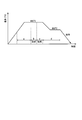
- FIG. 2 is a diagram showing a processing time and a processing temperature profile of the vacuum carburizing process and nitriding process according to the first embodiment of the present disclosure.
- the heat treatment of the workpiece W of the present embodiment is performed in the order of a: temperature rise / temperature rise holding step, b: carburization step, c: diffusion step, d: temperature drop / temperature fall hold step. Finally, oil cooling is performed.
- the workpiece W is placed in the heating furnace 1.
- the inside of the heating furnace 1 is evacuated and the inside of the heating furnace 1 is depressurized to a vacuum state (very low pressure atmosphere).
- vacuum refers to about 1/10 or less of atmospheric pressure.
- the inside of the heating furnace 1 is set to a vacuum state of 1 kPa or less, preferably 1 Pa or less.
- the heater of the heating furnace 1 is energized to raise the temperature inside the heating furnace 1 to a target temperature (930 ° C. in this embodiment). Subsequently, the inside of the heating furnace 1 is held for a predetermined time with the above target temperature. By providing this holding time, the temperature of the workpiece W can easily follow the temperature in the heating furnace 1 sufficiently. As a result, the temperature when shifting to the next carburizing step can be accurately controlled.
- acetylene gas is supplied into the heating furnace 1 as a carburizing gas.
- the pressure in the heating furnace 1 rises from a vacuum state to a predetermined pressure.
- the workpiece W is carburized by being exposed to a high-temperature carburizing gas atmosphere of 930 ° C. in the heating furnace 1 for a predetermined time.
- the carburizing gas is exhausted from the inside of the heating furnace 1 to obtain a vacuum state substantially equal to the pressure before the carburizing step.
- the heater of the heating furnace 1 is controlled to lower the temperature in the heating furnace 1 to a target temperature (850 ° C. in this embodiment).
- the inside of the heating furnace 1 is held for a predetermined time with the above target temperature. At that time, first, nitrogen gas (N 2 ) is supplied to the heating furnace 1, the pressure is increased to a target pressure, and then ammonia gas is supplied into the heating furnace 1.
- the carbon that has entered the vicinity of the surface of the workpiece W is diffused from the surface of the workpiece W to the inside.
- a part of the ammonia gas exposed to the high temperature atmosphere for a predetermined time in the heating furnace 1 is thermally decomposed to generate nitrogen gas (N 2 ) and hydrogen gas (H 2 ). Since the treatment in the diffusion step and the temperature lowering / temperature holding step is performed in an atmosphere of nitrogen gas (including hydrogen gas and ammonia gas), a nitride layer (for example, Fe 4 N) is formed on the surface of the workpiece W, The surface hardness and wear resistance of the workpiece W are improved. That is, the diffusion process and the temperature lowering / temperature holding process correspond to a nitriding process.
- the workpiece W is transferred to a cooling tank (not shown), and the workpiece W is oil-cooled from a high temperature of 850 ° C. to a normal temperature.
- the vacuum carburizing / nitriding treatment of the present embodiment is completed.
- the hardenability can be improved by adding the nitriding gas in the diffusion process and the temperature lowering / temperature holding process.
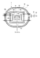
- FIG. 3 is a longitudinal cross-sectional view illustrating a configuration of the pyrolysis furnace 3 according to the first embodiment of the present disclosure.
- the pyrolysis furnace 3 of the present embodiment includes a reactant 31, a heating chamber 32, an introduction pipe 33, a vacuum vessel 34, and a vacuum pump 35.
- the reactant 31 functions as a catalyst for promoting the thermal decomposition reaction of ammonia gas.
- iron is used as the reactant 31. Iron becomes Fe 4 N or the like, and promotes a thermal decomposition reaction of ammonia gas by depriving nitrogen.
- the reactant 31 is made of, for example, a steel material. This reactant 31 is formed in a concave shape surrounding the tip 33 a of the introduction tube 33.
- the reactant 31 of the present embodiment is formed in a substantially bowl shape, and the opening bottom is provided so as to face the tip 33 a of the introduction tube 33.
- the heating chamber 32 contains the reactant 31 and heats it.
- the wall part is formed from the heat insulating material, and the reactant 31 is accommodated inside the wall part.
- a heater 32 a and a tip of a thermocouple 32 b are disposed inside the wall portion of the heating chamber 32.
- the wall portion of the heating chamber 32 is formed with a plurality of through holes 32c through which the heater 32a and the thermocouple 32b are disposed.
- the heater 32 a and the thermocouple 32 b control the temperature of the heating chamber 32.
- the introduction pipe 33 introduces ammonia gas into the heating chamber 32.
- the introduction tube 33 is connected to the vacuum pump 11, and a tip 33 a thereof is inserted through the wall portion of the heating chamber 32 to the inside of the heating chamber 32.
- Ammonia gas conveyed from the heating furnace 1 is discharged from the tip 33a of the introduction pipe 33.
- the vacuum vessel 34 surrounds the heating chamber 32.
- the vacuum vessel 34 is formed in a highly pressure-resistant shape, that is, a rounded substantially cylindrical shape.
- the vacuum vessel 34 is covered with a water cooling jacket 34a.
- the vacuum pump 35 evacuates the vacuum container 34. When the vacuum pump 35 is driven, the gas in the heating chamber 32 goes out of the heating chamber 32 through the through hole 32 c and is discharged to the outside of the vacuum vessel 34.
- an exhaust pipe 36 is provided on the downstream side of the vacuum pump 35.
- the nitrogen gas supply device 4 supplies nitrogen gas to the exhaust pipe 36.
- the nitrogen gas supply device 4 is provided to prevent reverse diffusion of gas from the downstream side of the vacuum pump 35 to the upstream side of the vacuum pump 35 by supplying nitrogen gas to the exhaust pipe 36. .
- the inside of the vacuum vessel 34 is evacuated in advance, and the inside of the heating chamber 32 is decompressed to be in a vacuum state (very low pressure atmosphere).
- vacuum refers to about 1/10 or less of atmospheric pressure.
- the vacuum state is 1 kPa or less, preferably 1 Pa or less.
- the heater 32a is energized to raise the temperature in the heating chamber 32 to a temperature suitable for the thermal decomposition reaction of ammonia gas.
- the temperature in the heating chamber 32 is raised to, for example, about 850 ° C.
- ammonia gas (including nitrogen gas and hydrogen gas) is discharged from the heating furnace 1 shown in FIG.
- the discharged ammonia gas is discharged into the heating chamber 32 from the tip 33a of the introduction pipe 33 as shown in FIG.
- the ammonia gas is exposed to a high-temperature atmosphere of 850 ° C. in the heating chamber 32 and is finally thermally decomposed by the action of the reactant 31 as shown in the following reaction formula (1).
- the reactant 31 of the present embodiment is formed in a concave shape surrounding the tip 33 a of the introduction tube 33. According to this configuration, since the ammonia gas discharged from the tip 33a of the introduction pipe 33 collides with the bottom surface of the concave portion of the reactant 31, the ammonia gas flows along the side surface of the concave portion. It is possible to ensure a long contact distance. For this reason, it takes a long time for the ammonia gas and the reactant 31 to come into contact with each other, and the thermal decomposition of the ammonia gas can be reliably performed.
- Nitrogen gas and hydrogen gas which are decomposition gases of ammonia gas, stay in the heating chamber 32 for a predetermined time, then go out of the heating chamber 32 through the through hole 32c, and are discharged to the outside of the vacuum vessel 34.
- the nitrogen gas and hydrogen gas are discharged to the downstream exhaust pipe 36 via the vacuum pump 35.
- the cracked gas of ammonia gas tends to have a higher concentration of hydrogen gas than nitrogen gas, as is apparent from the reaction formula (1).
- the nitrogen gas supply device 4 shown in FIG. 1 supplies nitrogen gas to the exhaust pipe 36 in order to prevent the flammable hydrogen gas from back-diffusing upstream from the vacuum pump 35. Thereby, safety can be improved.
- the pyrolysis furnace 3 is provided in parallel with the heating furnace 1 that performs vacuum carburizing / nitriding, and the ammonia gas discharged from the heating furnace 1 is heated after the vacuum carburizing / nitriding. It introduce
- the heating furnace 1 for heating the workpiece W and the ammonia gas for nitriding the workpiece W are supplied to the heating furnace 1.
- the ammonia gas supply device 2 and the thermal decomposition furnace 3 for thermally decomposing the ammonia gas discharged from the heating furnace 1 after nitriding the ammonia gas can be processed at low cost.
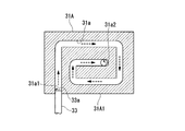
- FIGS. 4A and 4B are diagrams illustrating a configuration of a reactant 31A according to the second embodiment of the present disclosure.
- 4A is a longitudinal sectional view of the reactant 31A
- FIG. 4B is a bottom view of the reactant 31A.
- the reactant 31A of the second embodiment is different from the above-described embodiment in that it has a flow path 31a inside.
- the reactant 31A is formed in a block shape, the first end 31a1 of the channel 31a opens to the block bottom surface 31A1, and the second end 31a2 of the channel 31a opens to the block back surface 31A2 of the reactant 31A. .
- the channel 31a is formed in a spiral shape from the first end 31a1 toward the second end 31a2.
- the leading end 33a of the introduction pipe 33 is connected to the first end 31a1 of the flow path 31a.
- the ammonia gas discharged from the tip 33a of the introduction pipe 33 flows from the first end 31a1 to the second end 31a2 of the flow path 31a.
- the wall surface forming the flow path 31a is made of the reactant 31A, and the flow path 31a is formed in a spiral shape, so that the contact distance between the ammonia gas and the reactant 31 can be increased.
- the time which ammonia gas and the reaction material 31 touch becomes long, and thermal decomposition of ammonia gas can be performed more reliably.
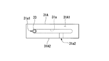
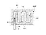
- FIGS. 5A and 5B are diagrams illustrating a configuration of a reactant 31B according to the third embodiment of the present disclosure.
- FIG. 5A is a longitudinal sectional view of the reactant 31B
- FIG. 5B is a bottom view of the reactant 31B.
- the reactant 31 ⁇ / b> B of the third embodiment is different from the above embodiment in that it has a flow path 31 b inside.
- the reactant 31B is formed in a block shape, the first end 31b1 of the channel 31b opens to the block bottom surface 31B1, and the second end 31b2 of the channel 31b opens to the block side surface 31B2 of the reactant 31B. .
- the flow path 31b is formed in a folded shape from the first end 31b1 toward the second end 31b2.
- a distal end 33a of the introduction pipe 33 is connected to the first end 31b1 of the flow path 31b.
- the ammonia gas discharged from the tip 33a of the introduction pipe 33 flows from the first end 31b1 of the flow path 31b toward the second end 31b2.
- the wall surface forming the flow path 31b is made of the reactant 31B, and the flow path 31b is formed in a zigzag shape so that the contact distance between the ammonia gas and the reactant 31 can be increased.
- the time which ammonia gas and the reaction material 31 touch becomes long, and thermal decomposition of ammonia gas can be performed more reliably.
- the content of the present disclosure is not limited to the above-described embodiment, and for example, the following modifications may be considered.
- other complicated labyrinth structures may be used except for the difficulty of manufacturing the flow path.
- the structure of the reactant may be appropriately divided according to the complexity of the flow path.
- a Vacuum carburizing equipment (heat treatment equipment) W Object to be treated 1 Heating furnace 2 Ammonia gas supply device 3 Pyrolysis furnace 4 Nitrogen gas supply devices 31, 31A, 31B Reactants 31a, 31b Channel 32 Heating chamber 33 Introducing pipe 33a Tip 34 Vacuum vessel 35 Vacuum pump 36 Exhaust pipe
Abstract
The present invention is characterized by inexpensively treating ammonia gas contained in an exhaust gas having undergone a nitriding process without performing burning, and without adsorption by using an adsorption agent, etc. A vacuum carburizing treatment device (A) according to the present disclosure has: a heating furnace (1) that heats an object to be processed (W); an ammonia gas supplying device (2) that supplies, to the heating furnace (1), ammonia gas for performing the nitriding process on the object to be processed (W); and a pyrolytic furnace (3) that pyrolyzes the ammonia gas discharged from the heating furnace (1) after the nitriding process.
Description
本開示は、熱処理装置に関する。
本願は、2015年5月1日に、日本に出願された特願2015-094167号に基づき優先権を主張し、その内容をここに援用する。 The present disclosure relates to a heat treatment apparatus.
This application claims priority based on Japanese Patent Application No. 2015-094167 filed in Japan on May 1, 2015, the contents of which are incorporated herein by reference.
被処理物の表面に硬度が必要とされる場合、浸炭処理等が一般的である。また、それ以上の硬度が必要とされる場合には、表面の窒化処理が行われることがある。このような窒化処理を行う熱処理装置として、例えば、下記特許文献1に記載の真空浸炭処理装置が知られている。この真空浸炭処理装置では、アセチレン等の浸炭用ガスを供給する浸炭処理と、浸炭用ガスの炭素を被処理物の表面に拡散させる拡散処理とが行われ、その拡散処理において窒化ガスが供給され、被処理物の表面に窒化層が形成され、被処理物の表面硬度や耐摩耗性を向上させる。
When the surface of the workpiece is required to have hardness, carburizing is generally used. In addition, when higher hardness is required, nitriding treatment of the surface may be performed. As a heat treatment apparatus for performing such nitriding treatment, for example, a vacuum carburizing apparatus described in Patent Document 1 below is known. In this vacuum carburizing apparatus, a carburizing process for supplying a carburizing gas such as acetylene and a diffusion process for diffusing carbon of the carburizing gas on the surface of the workpiece are performed, and a nitriding gas is supplied in the diffusion process. A nitride layer is formed on the surface of the object to be processed, and the surface hardness and abrasion resistance of the object to be processed are improved.
ところで、窒化処理の窒化ガスとしては、アンモニアガスがよく使用される。アンモニアガスは、刺激性が強い劇物であり、窒化処理後、加熱炉から排出されるアンモニアガスを適切に処理する必要がある。アンモニアの処理方法としては、アンモニアガスを燃焼させる燃焼法が古くから行われている。燃焼法では、燃焼廃ガスの規制の問題等があるため、近年では、燃焼させたアンモニアガスを水に溶け込ませたり、吸着材で吸着する等の処理が行われている。しかしながら、これらの処理を行う設備のランニングコストは、非常に高価である。
Incidentally, ammonia gas is often used as a nitriding gas for nitriding. Ammonia gas is a deleterious substance with strong irritation, and it is necessary to appropriately treat the ammonia gas discharged from the heating furnace after nitriding. As a method for treating ammonia, a combustion method for burning ammonia gas has long been performed. In the combustion method, there is a problem of regulation of combustion waste gas, and in recent years, treatments such as dissolving the burned ammonia gas in water or adsorbing with an adsorbent are performed. However, the running cost of equipment for performing these treatments is very expensive.
本開示は、上記問題点に鑑みてなされ、窒化処理用に使用するアンモニアガスを安価に処理することができる熱処理装置の提供を目的とする。
The present disclosure has been made in view of the above problems, and an object of the present disclosure is to provide a heat treatment apparatus capable of processing ammonia gas used for nitriding at low cost.
上記の課題を解決するために、本開示の第1の態様に係る熱処理装置は、被処理物を加熱する加熱炉と、被処理物を窒化処理するためのアンモニアガスを加熱炉に供給するアンモニアガス供給装置と、窒化処理後、加熱炉から排出されるアンモニアガスを熱分解する熱分解炉と、を有する。
In order to solve the above problems, a heat treatment apparatus according to the first aspect of the present disclosure includes a heating furnace that heats a workpiece, and ammonia that supplies ammonia gas for nitriding the workpiece to the heating furnace. A gas supply device; and a pyrolysis furnace that thermally decomposes ammonia gas discharged from the heating furnace after nitriding.
本開示では、窒化処理を行う加熱炉に熱分解炉を並設し、窒化処理後、加熱炉から排出されるアンモニアガスを熱分解炉で熱分解する。熱分解炉は、アンモニアガスを加熱により分解するため、燃焼廃ガスが出ず、また、アンモニアガスを処理する水や吸着材等の入換えや補充の必要もない。
したがって、本開示によれば、安価にアンモニアガスの処理を行うことができる熱処理装置が得られる。 In the present disclosure, a pyrolysis furnace is provided in parallel with a heating furnace that performs nitriding treatment, and after the nitriding treatment, ammonia gas discharged from the heating furnace is pyrolyzed in the pyrolysis furnace. Since the pyrolysis furnace decomposes ammonia gas by heating, no combustion waste gas is produced, and there is no need to replace or replenish water, adsorbents, etc. for processing the ammonia gas.
Therefore, according to the present disclosure, a heat treatment apparatus that can perform ammonia gas treatment at low cost is obtained.
以下、本開示の実施形態について図面を参照して説明する。なお、以下の説明では、本開示の熱処理装置として、真空浸炭処理装置を例示する。
Hereinafter, embodiments of the present disclosure will be described with reference to the drawings. In the following description, a vacuum carburizing apparatus is exemplified as the heat treatment apparatus of the present disclosure.
(第1実施形態)
図1は、本開示の第1実施形態に係る真空浸炭処理装置Aの概略構成を示すブロック図である。
図1に示すように、本実施形態の真空浸炭処理装置Aは、加熱炉1と、アンモニアガス供給装置2と、熱分解炉3と、窒素ガス供給装置4とを備えている。 (First embodiment)
FIG. 1 is a block diagram illustrating a schematic configuration of a vacuum carburizing apparatus A according to the first embodiment of the present disclosure.
As shown in FIG. 1, the vacuum carburizing apparatus A of the present embodiment includes aheating furnace 1, an ammonia gas supply device 2, a pyrolysis furnace 3, and a nitrogen gas supply device 4.
図1は、本開示の第1実施形態に係る真空浸炭処理装置Aの概略構成を示すブロック図である。
図1に示すように、本実施形態の真空浸炭処理装置Aは、加熱炉1と、アンモニアガス供給装置2と、熱分解炉3と、窒素ガス供給装置4とを備えている。 (First embodiment)
FIG. 1 is a block diagram illustrating a schematic configuration of a vacuum carburizing apparatus A according to the first embodiment of the present disclosure.
As shown in FIG. 1, the vacuum carburizing apparatus A of the present embodiment includes a
加熱炉1は、被処理物Wを加熱する。本実施形態の加熱炉1は、真空ポンプ11が接続された真空浸炭炉であり、鋼材からなる被処理物Wの真空浸炭処理・窒化処理を行う。加熱炉1の内部には、不図示のヒーター等が配置されている。また、加熱炉1には、不図示の浸炭用ガス供給装置が接続されており、浸炭用ガスとして例えばアセチレンガス(C2H2)が供給される。アンモニアガス供給装置2は、被処理物Wを窒化処理するためのアンモニアガス(NH3)を加熱炉1に供給する。
The heating furnace 1 heats the workpiece W. The heating furnace 1 of this embodiment is a vacuum carburizing furnace to which a vacuum pump 11 is connected, and performs a vacuum carburizing process and a nitriding process on a workpiece W made of steel. Inside the heating furnace 1, a heater (not shown) and the like are arranged. Further, a carburizing gas supply device (not shown) is connected to the heating furnace 1, and acetylene gas (C 2 H 2 ), for example, is supplied as the carburizing gas. The ammonia gas supply device 2 supplies ammonia gas (NH 3 ) for nitriding the workpiece W to the heating furnace 1.
図2は、本開示の第1実施形態に係る真空浸炭処理と窒化処理の処理時間と処理温度のプロファイルを示す図である。
本実施形態の被処理物Wの熱処理は、図2に示すように、a:昇温・昇温保持工程、b:浸炭工程、c:拡散工程、d:降温・降温保持工程、の順に行われ、最後に油冷が行われる。 FIG. 2 is a diagram showing a processing time and a processing temperature profile of the vacuum carburizing process and nitriding process according to the first embodiment of the present disclosure.
As shown in FIG. 2, the heat treatment of the workpiece W of the present embodiment is performed in the order of a: temperature rise / temperature rise holding step, b: carburization step, c: diffusion step, d: temperature drop / temperature fall hold step. Finally, oil cooling is performed.
本実施形態の熱処理では、先ず、被処理物Wを、加熱炉1内に載置する。次に、加熱炉1内を真空排気し、加熱炉1内を減圧して真空状態(極低圧雰囲気)とする。ここで、一般的な真空浸炭処理において、「真空」とは大気圧の1/10程度以下を指す。本実施形態では、加熱炉1内を1kPa以下、好ましくは、1Pa以下の真空状態とする。
In the heat treatment of this embodiment, first, the workpiece W is placed in the heating furnace 1. Next, the inside of the heating furnace 1 is evacuated and the inside of the heating furnace 1 is depressurized to a vacuum state (very low pressure atmosphere). Here, in a general vacuum carburizing process, “vacuum” refers to about 1/10 or less of atmospheric pressure. In the present embodiment, the inside of the heating furnace 1 is set to a vacuum state of 1 kPa or less, preferably 1 Pa or less.
次に、昇温・昇温保持工程では、加熱炉1のヒーターに通電して、加熱炉1内を目標とする温度(本実施形態では930℃)まで昇温させる。続いて、加熱炉1内を上記の目標温度にした状態で所定時間保持する。この保持時間を設けることにより、被処理物Wの温度が加熱炉1内の温度に十分に追従しやすくなる。その結果、次の浸炭工程へ移行する際の温度を正確に制御できる。
Next, in the temperature raising / temperature raising holding step, the heater of the heating furnace 1 is energized to raise the temperature inside the heating furnace 1 to a target temperature (930 ° C. in this embodiment). Subsequently, the inside of the heating furnace 1 is held for a predetermined time with the above target temperature. By providing this holding time, the temperature of the workpiece W can easily follow the temperature in the heating furnace 1 sufficiently. As a result, the temperature when shifting to the next carburizing step can be accurately controlled.
次に、浸炭工程では、加熱炉1内に浸炭用ガスとしてアセチレンガスを供給する。このとき、加熱炉1内の圧力は、真空状態から所定の圧力にまで上昇する。この浸炭工程において、被処理物Wは、加熱炉1内の930℃という高温の浸炭用ガス雰囲気に所定時間晒されることにより、浸炭処理される。
Next, in the carburizing step, acetylene gas is supplied into the heating furnace 1 as a carburizing gas. At this time, the pressure in the heating furnace 1 rises from a vacuum state to a predetermined pressure. In this carburizing step, the workpiece W is carburized by being exposed to a high-temperature carburizing gas atmosphere of 930 ° C. in the heating furnace 1 for a predetermined time.
次に、拡散工程では、加熱炉1内から浸炭用ガスを排気して、浸炭工程前の圧力と略同等の真空状態とする。次に、降温・降温保持工程では、加熱炉1のヒーターを制御して、加熱炉1内を目標とする温度(本実施形態では850℃)まで降温させる。続いて、加熱炉1内を上記の目標温度にした状態で所定時間保持する。その際に、先ず、窒素ガス(N2)を加熱炉1に供給し、目標とする圧力まで昇圧した後に、加熱炉1内にアンモニアガスを供給する。アンモニアガスを供給したら、加熱炉1の圧力が一定圧でコントロールを行えるよう真空排気回路のON/OFF制御を行う。その際、加熱炉1内の雰囲気を撹拌するための不図示のファンを作動させる。
Next, in the diffusion step, the carburizing gas is exhausted from the inside of the heating furnace 1 to obtain a vacuum state substantially equal to the pressure before the carburizing step. Next, in the temperature lowering / temperature holding step, the heater of the heating furnace 1 is controlled to lower the temperature in the heating furnace 1 to a target temperature (850 ° C. in this embodiment). Subsequently, the inside of the heating furnace 1 is held for a predetermined time with the above target temperature. At that time, first, nitrogen gas (N 2 ) is supplied to the heating furnace 1, the pressure is increased to a target pressure, and then ammonia gas is supplied into the heating furnace 1. When ammonia gas is supplied, ON / OFF control of the vacuum exhaust circuit is performed so that the pressure in the heating furnace 1 can be controlled at a constant pressure. At that time, a fan (not shown) for agitating the atmosphere in the heating furnace 1 is operated.
これにより、被処理物Wの表面近傍に浸入した炭素が被処理物Wの表面から内部へと拡散される。また、加熱炉1内で高温雰囲気に所定時間晒されたアンモニアガスの一部は熱分解し、窒素ガス(N2)と水素ガス(H2)が発生する。拡散工程及び降温・降温保持工程における処理は、窒素ガス(水素ガス及びアンモニアガスを含む)雰囲気下で行われるため、被処理物Wの表面に窒化層(例えばFe4N等)が形成され、被処理物Wの表面硬度や耐摩耗性が向上する。つまり、この拡散工程及び降温・降温保持工程が窒化処理工程に相当する。
Thereby, the carbon that has entered the vicinity of the surface of the workpiece W is diffused from the surface of the workpiece W to the inside. In addition, a part of the ammonia gas exposed to the high temperature atmosphere for a predetermined time in the heating furnace 1 is thermally decomposed to generate nitrogen gas (N 2 ) and hydrogen gas (H 2 ). Since the treatment in the diffusion step and the temperature lowering / temperature holding step is performed in an atmosphere of nitrogen gas (including hydrogen gas and ammonia gas), a nitride layer (for example, Fe 4 N) is formed on the surface of the workpiece W, The surface hardness and wear resistance of the workpiece W are improved. That is, the diffusion process and the temperature lowering / temperature holding process correspond to a nitriding process.
その後、被処理物Wを不図示の冷却槽に移送して、被処理物Wを850℃の高温から常温まで油冷する。以上の工程で、本実施形態の真空浸炭処理・窒化処理は完了する。本実施形態の熱処理によれば、拡散工程及び降温・降温保持工程における窒化ガスの添加により、焼入れ性の改善が見込める。
Thereafter, the workpiece W is transferred to a cooling tank (not shown), and the workpiece W is oil-cooled from a high temperature of 850 ° C. to a normal temperature. With the above steps, the vacuum carburizing / nitriding treatment of the present embodiment is completed. According to the heat treatment of this embodiment, the hardenability can be improved by adding the nitriding gas in the diffusion process and the temperature lowering / temperature holding process.
図1に戻り、熱分解炉3は、真空浸炭処理・窒化処理後、加熱炉1から排出されるアンモニアガスを熱分解する。なお、加熱炉1から排出されるアンモニアガスは、一部熱分解されており、窒素ガス(N2)と水素ガス(H2)とを含む。
図3は、本開示の第1実施形態に係る熱分解炉3の構成を示す縦断面図である。
図3に示すように、本実施形態の熱分解炉3は、反応物31と、加熱室32と、導入管33と、真空容器34と、真空ポンプ35とを備えている。 Returning to FIG. 1, thepyrolysis furnace 3 pyrolyzes the ammonia gas discharged from the heating furnace 1 after vacuum carburizing / nitriding. The ammonia gas discharged from the heating furnace 1 is partially pyrolyzed and contains nitrogen gas (N 2 ) and hydrogen gas (H 2 ).
FIG. 3 is a longitudinal cross-sectional view illustrating a configuration of thepyrolysis furnace 3 according to the first embodiment of the present disclosure.
As shown in FIG. 3, thepyrolysis furnace 3 of the present embodiment includes a reactant 31, a heating chamber 32, an introduction pipe 33, a vacuum vessel 34, and a vacuum pump 35.
図3は、本開示の第1実施形態に係る熱分解炉3の構成を示す縦断面図である。
図3に示すように、本実施形態の熱分解炉3は、反応物31と、加熱室32と、導入管33と、真空容器34と、真空ポンプ35とを備えている。 Returning to FIG. 1, the
FIG. 3 is a longitudinal cross-sectional view illustrating a configuration of the
As shown in FIG. 3, the
反応物31は、アンモニアガスの熱分解反応を促進させる触媒として機能する。本実施形態では、反応物31として鉄を使用する。鉄は、Fe4N等となり、窒素を奪うことで、アンモニアガスの熱分解反応を促進させる。反応物31は、例えば鉄鋼材から形成されている。
この反応物31は、導入管33の先端33aを囲う凹状に形成されている。本実施形態の反応物31は、略枡状に形成されており、その開口底部が、導入管33の先端33aと対向するように設けられている。 Thereactant 31 functions as a catalyst for promoting the thermal decomposition reaction of ammonia gas. In this embodiment, iron is used as the reactant 31. Iron becomes Fe 4 N or the like, and promotes a thermal decomposition reaction of ammonia gas by depriving nitrogen. The reactant 31 is made of, for example, a steel material.
Thisreactant 31 is formed in a concave shape surrounding the tip 33 a of the introduction tube 33. The reactant 31 of the present embodiment is formed in a substantially bowl shape, and the opening bottom is provided so as to face the tip 33 a of the introduction tube 33.
この反応物31は、導入管33の先端33aを囲う凹状に形成されている。本実施形態の反応物31は、略枡状に形成されており、その開口底部が、導入管33の先端33aと対向するように設けられている。 The
This
加熱室32は、反応物31を収容し、加熱する。加熱室32は、壁部が断熱材から形成されており、その壁部の内側に反応物31を収容している。また、加熱室32の壁部の内側には、ヒーター32aと、熱電対32bの先端とが配置されている。加熱室32の壁部には、ヒーター32aと、熱電対32bとが貫通して配置される貫通孔32cが複数形成されている。ヒーター32a及び熱電対32bは、加熱室32の温度を制御する。
The heating chamber 32 contains the reactant 31 and heats it. As for the heating chamber 32, the wall part is formed from the heat insulating material, and the reactant 31 is accommodated inside the wall part. In addition, a heater 32 a and a tip of a thermocouple 32 b are disposed inside the wall portion of the heating chamber 32. The wall portion of the heating chamber 32 is formed with a plurality of through holes 32c through which the heater 32a and the thermocouple 32b are disposed. The heater 32 a and the thermocouple 32 b control the temperature of the heating chamber 32.
導入管33は、加熱室32にアンモニアガスを導入する。導入管33は、図1に示すように、真空ポンプ11と接続されており、その先端33aが加熱室32の壁部を貫通して加熱室32の内側まで挿入されている。導入管33の先端33aからは、加熱炉1から搬送されてきたアンモニアガスが吐出される。
The introduction pipe 33 introduces ammonia gas into the heating chamber 32. As shown in FIG. 1, the introduction tube 33 is connected to the vacuum pump 11, and a tip 33 a thereof is inserted through the wall portion of the heating chamber 32 to the inside of the heating chamber 32. Ammonia gas conveyed from the heating furnace 1 is discharged from the tip 33a of the introduction pipe 33.
真空容器34は、加熱室32を囲う。真空容器34は、圧力耐性の高い形状つまり丸みを帯びた略円筒形状に形成されている。真空容器34は、水冷ジャケット34aで覆われている。
真空ポンプ35は、真空容器34内を真空排気する。真空ポンプ35が駆動すると、加熱室32内のガスは、貫通孔32cを通って加熱室32外に出て、真空容器34の外部に排出される。 Thevacuum vessel 34 surrounds the heating chamber 32. The vacuum vessel 34 is formed in a highly pressure-resistant shape, that is, a rounded substantially cylindrical shape. The vacuum vessel 34 is covered with a water cooling jacket 34a.
Thevacuum pump 35 evacuates the vacuum container 34. When the vacuum pump 35 is driven, the gas in the heating chamber 32 goes out of the heating chamber 32 through the through hole 32 c and is discharged to the outside of the vacuum vessel 34.
真空ポンプ35は、真空容器34内を真空排気する。真空ポンプ35が駆動すると、加熱室32内のガスは、貫通孔32cを通って加熱室32外に出て、真空容器34の外部に排出される。 The
The
図1に戻り、真空ポンプ35の下流側には、排気管36が設けられている。
窒素ガス供給装置4は、排気管36に窒素ガスを供給する。窒素ガス供給装置4は、排気管36に窒素ガスを供給することで、真空ポンプ35よりも下流側から、真空ポンプ35の上流側へガスが逆拡散することを防止するために設けられている。 Returning to FIG. 1, anexhaust pipe 36 is provided on the downstream side of the vacuum pump 35.
The nitrogengas supply device 4 supplies nitrogen gas to the exhaust pipe 36. The nitrogen gas supply device 4 is provided to prevent reverse diffusion of gas from the downstream side of the vacuum pump 35 to the upstream side of the vacuum pump 35 by supplying nitrogen gas to the exhaust pipe 36. .
窒素ガス供給装置4は、排気管36に窒素ガスを供給する。窒素ガス供給装置4は、排気管36に窒素ガスを供給することで、真空ポンプ35よりも下流側から、真空ポンプ35の上流側へガスが逆拡散することを防止するために設けられている。 Returning to FIG. 1, an
The nitrogen
次に、上記構成を有する熱分解炉3の動作について説明する。
Next, the operation of the pyrolysis furnace 3 having the above configuration will be described.
熱分解炉3では、予め真空容器34内を真空排気し、加熱室32内を減圧して真空状態(極低圧雰囲気)とする。ここで、「真空」とは大気圧の1/10程度以下を指す。本実施形態では、1kPa以下、好ましくは、1Pa以下の真空状態とする。次に、ヒーター32aに通電して、加熱室32内をアンモニアガスの熱分解反応に適した温度まで昇温させる。本実施形態では、反応物31として鉄を使用するため、加熱室32内の温度を例えば850℃程度まで昇温させる。
In the pyrolysis furnace 3, the inside of the vacuum vessel 34 is evacuated in advance, and the inside of the heating chamber 32 is decompressed to be in a vacuum state (very low pressure atmosphere). Here, “vacuum” refers to about 1/10 or less of atmospheric pressure. In the present embodiment, the vacuum state is 1 kPa or less, preferably 1 Pa or less. Next, the heater 32a is energized to raise the temperature in the heating chamber 32 to a temperature suitable for the thermal decomposition reaction of ammonia gas. In this embodiment, since iron is used as the reactant 31, the temperature in the heating chamber 32 is raised to, for example, about 850 ° C.
上述した真空浸炭処理・窒化処理の後、図1に示す加熱炉1からアンモニアガス(窒素ガス、水素ガスを含む)が排出される。排出されたアンモニアガスは、図3に示すように、導入管33の先端33aから加熱室32内に吐出される。アンモニアガスは、加熱室32内の850℃という高温雰囲気に晒され、また、反応物31の作用により、最終的に下記反応式(1)のように熱分解される。
2NH3 → N2 + 3H2 …(1) After the above-described vacuum carburizing / nitriding treatment, ammonia gas (including nitrogen gas and hydrogen gas) is discharged from theheating furnace 1 shown in FIG. The discharged ammonia gas is discharged into the heating chamber 32 from the tip 33a of the introduction pipe 33 as shown in FIG. The ammonia gas is exposed to a high-temperature atmosphere of 850 ° C. in the heating chamber 32 and is finally thermally decomposed by the action of the reactant 31 as shown in the following reaction formula (1).
2NH 3 → N 2 + 3H 2 (1)
2NH3 → N2 + 3H2 …(1) After the above-described vacuum carburizing / nitriding treatment, ammonia gas (including nitrogen gas and hydrogen gas) is discharged from the
2NH 3 → N 2 + 3H 2 (1)
ここで、本実施形態の反応物31は、導入管33の先端33aを囲う凹状に形成されている。この構成によれば、導入管33の先端33aから吐出されたアンモニアガスは、反応物31の凹部分の底面に衝突した後、凹部分の側面に沿って流れるため、アンモニアガスと反応物31との接触距離を長く確保することができる。このため、アンモニアガスと反応物31とが触れる時間が長くなり、アンモニアガスの熱分解を確実に行うことができる。
Here, the reactant 31 of the present embodiment is formed in a concave shape surrounding the tip 33 a of the introduction tube 33. According to this configuration, since the ammonia gas discharged from the tip 33a of the introduction pipe 33 collides with the bottom surface of the concave portion of the reactant 31, the ammonia gas flows along the side surface of the concave portion. It is possible to ensure a long contact distance. For this reason, it takes a long time for the ammonia gas and the reactant 31 to come into contact with each other, and the thermal decomposition of the ammonia gas can be reliably performed.
アンモニアガスの分解ガスである窒素ガス及び水素ガスは、加熱室32で所定時間滞留した後、貫通孔32cを通って加熱室32外に出て、真空容器34の外部に排出される。
この窒素ガス及び水素ガスは、真空ポンプ35を介して下流側の排気管36に排出される。ここで、アンモニアガスの分解ガスは、上記反応式(1)から明らかなように、窒素ガスよりも水素ガスの濃度が高くなる傾向にある。このため、図1に示す窒素ガス供給装置4は、燃焼性を有する水素ガスが真空ポンプ35より上流側へ逆拡散することを防止するために、排気管36に窒素ガスを供給する。これにより、安全性を向上させることができる。 Nitrogen gas and hydrogen gas, which are decomposition gases of ammonia gas, stay in theheating chamber 32 for a predetermined time, then go out of the heating chamber 32 through the through hole 32c, and are discharged to the outside of the vacuum vessel 34.
The nitrogen gas and hydrogen gas are discharged to thedownstream exhaust pipe 36 via the vacuum pump 35. Here, the cracked gas of ammonia gas tends to have a higher concentration of hydrogen gas than nitrogen gas, as is apparent from the reaction formula (1). For this reason, the nitrogen gas supply device 4 shown in FIG. 1 supplies nitrogen gas to the exhaust pipe 36 in order to prevent the flammable hydrogen gas from back-diffusing upstream from the vacuum pump 35. Thereby, safety can be improved.
この窒素ガス及び水素ガスは、真空ポンプ35を介して下流側の排気管36に排出される。ここで、アンモニアガスの分解ガスは、上記反応式(1)から明らかなように、窒素ガスよりも水素ガスの濃度が高くなる傾向にある。このため、図1に示す窒素ガス供給装置4は、燃焼性を有する水素ガスが真空ポンプ35より上流側へ逆拡散することを防止するために、排気管36に窒素ガスを供給する。これにより、安全性を向上させることができる。 Nitrogen gas and hydrogen gas, which are decomposition gases of ammonia gas, stay in the
The nitrogen gas and hydrogen gas are discharged to the
以上のように、本実施形態では、真空浸炭処理・窒化処理を行う加熱炉1に熱分解炉3を並設し、真空浸炭処理・窒化処理後、加熱炉1から排出されるアンモニアガスを熱分解炉3に導入し、真空状態で加熱(850℃程度)し、熱分解する。熱分解炉3は、アンモニアガスを加熱により分解するため、燃焼廃ガスが出ず、また、アンモニアガスを処理する水や吸着材等の入換えや補充の必要もない。したがって、本実施形態では、安価にアンモニアガスの処理を行うことができる。
As described above, in this embodiment, the pyrolysis furnace 3 is provided in parallel with the heating furnace 1 that performs vacuum carburizing / nitriding, and the ammonia gas discharged from the heating furnace 1 is heated after the vacuum carburizing / nitriding. It introduce | transduces into the decomposition furnace 3, heats in a vacuum state (about 850 degreeC), and thermally decomposes. Since the pyrolysis furnace 3 decomposes ammonia gas by heating, combustion waste gas does not come out, and there is no need to replace or replenish water, adsorbent, or the like for processing the ammonia gas. Therefore, in this embodiment, the ammonia gas can be processed at low cost.
このように、上述の本実施形態の真空浸炭処理装置Aによれば、被処理物Wを加熱する加熱炉1と、被処理物Wを窒化処理するためのアンモニアガスを加熱炉1に供給するアンモニアガス供給装置2と、窒化処理後、加熱炉1から排出されるアンモニアガスを熱分解する熱分解炉3と、を有することで、安価にアンモニアガスの処理を行うことができる。
Thus, according to the above-described vacuum carburizing apparatus A of the present embodiment, the heating furnace 1 for heating the workpiece W and the ammonia gas for nitriding the workpiece W are supplied to the heating furnace 1. By having the ammonia gas supply device 2 and the thermal decomposition furnace 3 for thermally decomposing the ammonia gas discharged from the heating furnace 1 after nitriding, the ammonia gas can be processed at low cost.
(第2実施形態)
次に、本開示の第2実施形態について説明する。以下の説明において、上述の実施形態と同一又は同等の構成については同一の符号を付し、その説明を簡略若しくは省略する。 (Second Embodiment)
Next, a second embodiment of the present disclosure will be described. In the following description, the same or equivalent components as those in the above-described embodiment are denoted by the same reference numerals, and the description thereof is simplified or omitted.
図4A及びBは、本開示の第2実施形態に係る反応物31Aの構成を示す図である。図4Aは、反応物31Aの縦断面図であり、図4Bは、反応物31Aの底面図である。
第2実施形態の反応物31Aは、図4A及びBに示すように、内部に流路31aを有する点で、上記実施形態と異なる。 4A and 4B are diagrams illustrating a configuration of areactant 31A according to the second embodiment of the present disclosure. 4A is a longitudinal sectional view of the reactant 31A, and FIG. 4B is a bottom view of the reactant 31A.
As shown in FIGS. 4A and B, thereactant 31A of the second embodiment is different from the above-described embodiment in that it has a flow path 31a inside.
第2実施形態の反応物31Aは、図4A及びBに示すように、内部に流路31aを有する点で、上記実施形態と異なる。 4A and 4B are diagrams illustrating a configuration of a
As shown in FIGS. 4A and B, the
反応物31Aは、ブロック状に形成されており、流路31aの第1端31a1はブロック底面31A1に開口し、流路31aの第2端31a2は反応物31Aのブロック背面31A2に開口している。流路31aは、第1端31a1から第2端31a2に向かって渦巻き状に形成されている。流路31aの第1端31a1には、導入管33の先端33aが接続されている。
The reactant 31A is formed in a block shape, the first end 31a1 of the channel 31a opens to the block bottom surface 31A1, and the second end 31a2 of the channel 31a opens to the block back surface 31A2 of the reactant 31A. . The channel 31a is formed in a spiral shape from the first end 31a1 toward the second end 31a2. The leading end 33a of the introduction pipe 33 is connected to the first end 31a1 of the flow path 31a.
上記構成の第2実施形態によれば、導入管33の先端33aから吐出されたアンモニアガスが、流路31aの第1端31a1から第2端31a2に向かって流れる。流路31aを形成する壁面は、反応物31Aからなり、流路31aは渦巻き状に形成されているため、アンモニアガスと反応物31との接触距離を長く取ることができる。このように第2実施形態では、アンモニアガスと反応物31とが触れる時間が長くなり、アンモニアガスの熱分解をより確実に行うことができる。
According to the second embodiment configured as described above, the ammonia gas discharged from the tip 33a of the introduction pipe 33 flows from the first end 31a1 to the second end 31a2 of the flow path 31a. The wall surface forming the flow path 31a is made of the reactant 31A, and the flow path 31a is formed in a spiral shape, so that the contact distance between the ammonia gas and the reactant 31 can be increased. Thus, in 2nd Embodiment, the time which ammonia gas and the reaction material 31 touch becomes long, and thermal decomposition of ammonia gas can be performed more reliably.
(第3実施形態)
次に、本開示の第3実施形態について説明する。以下の説明において、上述の実施形態と同一又は同等の構成については同一の符号を付し、その説明を簡略若しくは省略する。 (Third embodiment)
Next, a third embodiment of the present disclosure will be described. In the following description, the same or equivalent components as those in the above-described embodiment are denoted by the same reference numerals, and the description thereof is simplified or omitted.
図5A及びBは、本開示の第3実施形態に係る反応物31Bの構成を示す図である。図5Aは、反応物31Bの縦断面図であり、図5Bは、反応物31Bの底面図である。
第3実施形態の反応物31Bは、図5A及びBに示すように、内部に流路31bを有する点で、上記実施形態と異なる。 5A and 5B are diagrams illustrating a configuration of areactant 31B according to the third embodiment of the present disclosure. FIG. 5A is a longitudinal sectional view of the reactant 31B, and FIG. 5B is a bottom view of the reactant 31B.
As shown in FIGS. 5A and 5B, thereactant 31 </ b> B of the third embodiment is different from the above embodiment in that it has a flow path 31 b inside.
第3実施形態の反応物31Bは、図5A及びBに示すように、内部に流路31bを有する点で、上記実施形態と異なる。 5A and 5B are diagrams illustrating a configuration of a
As shown in FIGS. 5A and 5B, the
反応物31Bは、ブロック状に形成されており、流路31bの第1端31b1はブロック底面31B1に開口し、流路31bの第2端31b2は反応物31Bのブロック側面31B2に開口している。流路31bは、第1端31b1から第2端31b2に向かってつづら折り状に形成されている。流路31bの第1端31b1には、導入管33の先端33aが接続されている。
The reactant 31B is formed in a block shape, the first end 31b1 of the channel 31b opens to the block bottom surface 31B1, and the second end 31b2 of the channel 31b opens to the block side surface 31B2 of the reactant 31B. . The flow path 31b is formed in a folded shape from the first end 31b1 toward the second end 31b2. A distal end 33a of the introduction pipe 33 is connected to the first end 31b1 of the flow path 31b.
上記構成の第3実施形態によれば、導入管33の先端33aから吐出されたアンモニアガスが、流路31bの第1端31b1から第2端31b2に向かって流れる。流路31bを形成する壁面は、反応物31Bからなり、流路31bはつづら折り状に形成されているため、アンモニアガスと反応物31との接触距離を長く取ることができる。このように第3実施形態では、アンモニアガスと反応物31とが触れる時間が長くなり、アンモニアガスの熱分解をより確実に行うことができる。
According to the third embodiment configured as described above, the ammonia gas discharged from the tip 33a of the introduction pipe 33 flows from the first end 31b1 of the flow path 31b toward the second end 31b2. The wall surface forming the flow path 31b is made of the reactant 31B, and the flow path 31b is formed in a zigzag shape so that the contact distance between the ammonia gas and the reactant 31 can be increased. Thus, in 3rd Embodiment, the time which ammonia gas and the reaction material 31 touch becomes long, and thermal decomposition of ammonia gas can be performed more reliably.
なお、本開示の内容は上記実施形態に限定されず、例えば以下のような変形例が考えられる。
(1)上記第2実施形態、第3実施形態では、反応物が渦巻状やつづら折り状の流路を有する構成について説明したが、本開示の内容はこれに限定されない。例えば、流路の製作の困難性を除けば、他の複雑なラビリンス構造を用いてもよい。また、反応物は流路の複雑さに応じて適宜、構造を分割してもよい。 Note that the content of the present disclosure is not limited to the above-described embodiment, and for example, the following modifications may be considered.
(1) In the second embodiment and the third embodiment described above, the configuration in which the reactant has a spiral or zigzag flow path has been described, but the content of the present disclosure is not limited thereto. For example, other complicated labyrinth structures may be used except for the difficulty of manufacturing the flow path. In addition, the structure of the reactant may be appropriately divided according to the complexity of the flow path.
(2)また、上記実施形態では、加熱炉において真空浸炭処理・窒化処理を行うと説明したが、本開示の内容はこれに限定されない。例えば、加熱炉において窒化処理のみを行ってもよい。
(2) Moreover, although the said embodiment demonstrated performing a vacuum carburizing process and nitriding process in a heating furnace, the content of this indication is not limited to this. For example, you may perform only a nitriding process in a heating furnace.
本開示によれば、窒化処理用に使用するアンモニアガスを安価に処理することが可能な真空浸炭処理装置を提供することができる。
According to the present disclosure, it is possible to provide a vacuum carburizing apparatus capable of processing ammonia gas used for nitriding at low cost.
A 真空浸炭処理装置(熱処理装置)
W 被処理物
1 加熱炉
2 アンモニアガス供給装置
3 熱分解炉
4 窒素ガス供給装置
31,31A,31B 反応物
31a,31b 流路
32 加熱室
33 導入管
33a 先端
34 真空容器
35 真空ポンプ
36 排気管 A Vacuum carburizing equipment (heat treatment equipment)
W Object to be treated 1Heating furnace 2 Ammonia gas supply device 3 Pyrolysis furnace 4 Nitrogen gas supply devices 31, 31A, 31B Reactants 31a, 31b Channel 32 Heating chamber 33 Introducing pipe 33a Tip 34 Vacuum vessel 35 Vacuum pump 36 Exhaust pipe
W 被処理物
1 加熱炉
2 アンモニアガス供給装置
3 熱分解炉
4 窒素ガス供給装置
31,31A,31B 反応物
31a,31b 流路
32 加熱室
33 導入管
33a 先端
34 真空容器
35 真空ポンプ
36 排気管 A Vacuum carburizing equipment (heat treatment equipment)
W Object to be treated 1
Claims (7)
- 被処理物を加熱する加熱炉と、
前記被処理物を窒化処理するためのアンモニアガスを前記加熱炉に供給するアンモニアガス供給装置と、
前記窒化処理後、前記加熱炉から排出される前記アンモニアガスを熱分解する熱分解炉と、を有する熱処理装置。 A heating furnace for heating an object to be processed;
An ammonia gas supply device for supplying ammonia gas for nitriding the workpiece to the heating furnace;
A heat treatment apparatus comprising: a pyrolysis furnace for thermally decomposing the ammonia gas discharged from the heating furnace after the nitriding treatment. - 前記熱分解炉は、
前記アンモニアガスの熱分解反応を促進させる反応物と、
前記反応物を収容し、加熱する加熱室と、
前記加熱室に前記アンモニアガスを導入する導入管と、
前記加熱室を囲う真空容器と、
前記真空容器内を真空排気する真空ポンプと、を有する請求項1に記載の熱処理装置。 The pyrolysis furnace is
A reactant that promotes a thermal decomposition reaction of the ammonia gas;
A heating chamber for containing and heating the reactants;
An introduction pipe for introducing the ammonia gas into the heating chamber;
A vacuum vessel surrounding the heating chamber;
The heat treatment apparatus according to claim 1, further comprising: a vacuum pump that evacuates the vacuum vessel. - 前記反応物は、前記導入管の先端を囲う凹状に形成されている請求項2に記載の熱処理装置。 The heat treatment apparatus according to claim 2, wherein the reactant is formed in a concave shape surrounding a tip of the introduction tube.
- 前記反応物は、内部に流路を有し、
前記導入管の先端は、前記流路に接続されている請求項2に記載の熱処理装置。 The reactant has a flow path inside,
The heat treatment apparatus according to claim 2, wherein a leading end of the introduction pipe is connected to the flow path. - 前記流路は、渦巻き状に形成されている請求項4に記載の熱処理装置。 The heat treatment apparatus according to claim 4, wherein the flow path is formed in a spiral shape.
- 前記流路は、つづら折り状に形成されている請求項4に記載の熱処理装置。 The heat treatment apparatus according to claim 4, wherein the flow path is formed in a zigzag shape.
- 前記真空ポンプの下流側に設けられた排気管と、
前記排気管に窒素ガスを供給する窒素ガス供給装置と、を有する請求項2~6のいずれか一項に記載の熱処理装置。 An exhaust pipe provided downstream of the vacuum pump;
The heat treatment apparatus according to any one of claims 2 to 6, further comprising a nitrogen gas supply apparatus that supplies nitrogen gas to the exhaust pipe.
Priority Applications (4)
| Application Number | Priority Date | Filing Date | Title |
|---|---|---|---|
| JP2017516564A JP6407420B2 (en) | 2015-05-01 | 2016-03-07 | Heat treatment equipment |
| EP16789470.8A EP3290844B1 (en) | 2015-05-01 | 2016-03-07 | Heat treating device |
| CN201680025014.6A CN107532853B (en) | 2015-05-01 | 2016-03-07 | Heat treatment apparatus |
| US15/716,707 US10557180B2 (en) | 2015-05-01 | 2017-09-27 | Heat treating device |
Applications Claiming Priority (2)
| Application Number | Priority Date | Filing Date | Title |
|---|---|---|---|
| JP2015094167 | 2015-05-01 | ||
| JP2015-094167 | 2015-05-01 |
Related Child Applications (1)
| Application Number | Title | Priority Date | Filing Date |
|---|---|---|---|
| US15/716,707 Continuation US10557180B2 (en) | 2015-05-01 | 2017-09-27 | Heat treating device |
Publications (1)
| Publication Number | Publication Date |
|---|---|
| WO2016178334A1 true WO2016178334A1 (en) | 2016-11-10 |
Family
ID=57217635
Family Applications (1)
| Application Number | Title | Priority Date | Filing Date |
|---|---|---|---|
| PCT/JP2016/056964 WO2016178334A1 (en) | 2015-05-01 | 2016-03-07 | Heat treating device |
Country Status (5)
| Country | Link |
|---|---|
| US (1) | US10557180B2 (en) |
| EP (1) | EP3290844B1 (en) |
| JP (1) | JP6407420B2 (en) |
| CN (1) | CN107532853B (en) |
| WO (1) | WO2016178334A1 (en) |
Cited By (2)
| Publication number | Priority date | Publication date | Assignee | Title |
|---|---|---|---|---|
| CN107916390A (en) * | 2017-11-16 | 2018-04-17 | 无锡佳力欣精密机械有限公司 | A kind of ferrous based powder metallurgical thrust bearing nitriding system and its technique |
| JP2019014931A (en) * | 2017-07-05 | 2019-01-31 | 日産自動車株式会社 | Heat treatment method for steel material component |
Families Citing this family (2)
| Publication number | Priority date | Publication date | Assignee | Title |
|---|---|---|---|---|
| CN108310944A (en) * | 2018-02-01 | 2018-07-24 | 江苏佳铝实业股份有限公司 | Nitrogenize device for recycling exhaust gas |
| FR3132720A1 (en) * | 2022-02-11 | 2023-08-18 | Skf Aerospace France | Method of strengthening a steel part by carbonitriding |
Citations (4)
| Publication number | Priority date | Publication date | Assignee | Title |
|---|---|---|---|---|
| JPH03105194A (en) * | 1989-09-19 | 1991-05-01 | Nippon Techno:Kk | Exhaust gas processing device for gas nitriding furnace |
| JPH10306364A (en) * | 1994-05-25 | 1998-11-17 | Nippon Techno:Kk | Gas nitrosulphurizing method and device |
| JP2009186140A (en) * | 2008-02-08 | 2009-08-20 | Oriental Engineering Co Ltd | Gas nitriding furnace and gas soft nitriding furnace |
| JP2012192349A (en) * | 2011-03-16 | 2012-10-11 | Sumitomo Electric Ind Ltd | Gas treatment system |
Family Cites Families (11)
| Publication number | Priority date | Publication date | Assignee | Title |
|---|---|---|---|---|
| US1915120A (en) * | 1930-08-01 | 1933-06-20 | Du Pont | Apparatus for decomposing ammonia |
| JPS5514839A (en) * | 1978-07-14 | 1980-02-01 | Kawasaki Heavy Ind Ltd | Treating method for ion nitriding |
| JPH0815311B2 (en) * | 1986-01-28 | 1996-02-14 | 株式会社東芝 | Color document image processing device |
| JPH0512277Y2 (en) | 1986-04-22 | 1993-03-29 | ||
| JP2693382B2 (en) * | 1994-07-26 | 1997-12-24 | リヒト精光株式会社 | Composite diffusion nitriding method and device, and nitride production method |
| US6024893A (en) * | 1998-06-24 | 2000-02-15 | Caterpillar Inc. | Method for controlling a nitriding furnace |
| JP3999941B2 (en) | 2001-02-19 | 2007-10-31 | 株式会社荏原製作所 | Method and apparatus for processing gas containing NH3 |
| JP5266910B2 (en) | 2008-06-26 | 2013-08-21 | トヨタ自動車株式会社 | Heat treatment jig and heat treatment apparatus |
| JP5577573B2 (en) | 2008-08-29 | 2014-08-27 | 株式会社Ihi | Vacuum carburizing method and vacuum carburizing apparatus |
| CN203612947U (en) * | 2013-08-01 | 2014-05-28 | 和敬动力系统科技(上海)有限公司 | Plate-type ammonia decomposition hydrogen production device |
| CN203402922U (en) * | 2013-08-01 | 2014-01-22 | 和敬动力系统科技(上海)有限公司 | Tubular ammonia-decomposition hydrogen production device |
-
2016
- 2016-03-07 CN CN201680025014.6A patent/CN107532853B/en active Active
- 2016-03-07 JP JP2017516564A patent/JP6407420B2/en active Active
- 2016-03-07 WO PCT/JP2016/056964 patent/WO2016178334A1/en active Application Filing
- 2016-03-07 EP EP16789470.8A patent/EP3290844B1/en active Active
-
2017
- 2017-09-27 US US15/716,707 patent/US10557180B2/en active Active
Patent Citations (4)
| Publication number | Priority date | Publication date | Assignee | Title |
|---|---|---|---|---|
| JPH03105194A (en) * | 1989-09-19 | 1991-05-01 | Nippon Techno:Kk | Exhaust gas processing device for gas nitriding furnace |
| JPH10306364A (en) * | 1994-05-25 | 1998-11-17 | Nippon Techno:Kk | Gas nitrosulphurizing method and device |
| JP2009186140A (en) * | 2008-02-08 | 2009-08-20 | Oriental Engineering Co Ltd | Gas nitriding furnace and gas soft nitriding furnace |
| JP2012192349A (en) * | 2011-03-16 | 2012-10-11 | Sumitomo Electric Ind Ltd | Gas treatment system |
Non-Patent Citations (1)
| Title |
|---|
| See also references of EP3290844A4 * |
Cited By (2)
| Publication number | Priority date | Publication date | Assignee | Title |
|---|---|---|---|---|
| JP2019014931A (en) * | 2017-07-05 | 2019-01-31 | 日産自動車株式会社 | Heat treatment method for steel material component |
| CN107916390A (en) * | 2017-11-16 | 2018-04-17 | 无锡佳力欣精密机械有限公司 | A kind of ferrous based powder metallurgical thrust bearing nitriding system and its technique |
Also Published As
| Publication number | Publication date |
|---|---|
| JPWO2016178334A1 (en) | 2017-10-12 |
| EP3290844B1 (en) | 2022-04-13 |
| CN107532853A (en) | 2018-01-02 |
| JP6407420B2 (en) | 2018-10-17 |
| EP3290844A1 (en) | 2018-03-07 |
| EP3290844A4 (en) | 2018-10-31 |
| US10557180B2 (en) | 2020-02-11 |
| CN107532853B (en) | 2020-06-30 |
| US20180016651A1 (en) | 2018-01-18 |
Similar Documents
| Publication | Publication Date | Title |
|---|---|---|
| JP6407420B2 (en) | Heat treatment equipment | |
| JP3960697B2 (en) | Carburizing and carbonitriding methods | |
| JP6171090B2 (en) | Heat treatment equipment | |
| WO2016013360A1 (en) | Carburizing device | |
| JP6168008B2 (en) | Steel manufacturing method | |
| JP2011026647A (en) | Gas carburization treatment device and gas carburization method | |
| CN107523783A (en) | Surface treatment method and surface processing device | |
| US9540721B2 (en) | Method of carburizing | |
| JP6543213B2 (en) | Surface hardening method and surface hardening apparatus | |
| JP4934828B2 (en) | Nitriding furnace and nitriding method | |
| JP2008260994A (en) | Method for producing carburized product | |
| JP4169864B2 (en) | Method of carburizing steel | |
| JP6543208B2 (en) | Gas carburizing method and gas carburizing apparatus | |
| JP2009138207A (en) | Method and apparatus for manufacturing steel having carbon concentration-controlled steel surface | |
| KR102243284B1 (en) | Nitriding Apparatus and Nitriding Treatment Method | |
| WO2011102084A1 (en) | Elimination apparatus and elimination method | |
| JP6443961B2 (en) | Carburizing equipment | |
| JP5683416B2 (en) | Method for improving insulation resistance of vacuum heating furnace | |
| KR101911622B1 (en) | Method and apparatus for gas nitriding | |
| JP2009299122A (en) | Nitriding-quenching method, heater for nitriding-quenching and nitriding-quenching apparatus | |
| JP2005120404A (en) | Gas carburization method, gas carbonitriding method, and surface treatment device | |
| JPH03291368A (en) | Vacuum carburizing method and vacuum carburizing furnace | |
| JP4180492B2 (en) | Carburizing equipment | |
| WO2014174949A1 (en) | Surface modification device for alloy steel component, method for surface modification of alloy steel component, and manufacturing method for alloy steel component | |
| JP2024034774A (en) | Vacuum carburizing method and vacuum carburizing equipment |
Legal Events
| Date | Code | Title | Description |
|---|---|---|---|
| 121 | Ep: the epo has been informed by wipo that ep was designated in this application |
Ref document number: 16789470 Country of ref document: EP Kind code of ref document: A1 |
|
| ENP | Entry into the national phase |
Ref document number: 2017516564 Country of ref document: JP Kind code of ref document: A |
|
| REEP | Request for entry into the european phase |
Ref document number: 2016789470 Country of ref document: EP |
|
| NENP | Non-entry into the national phase |
Ref country code: DE |