WO2016175598A1 - 디스플레이 유닛 제조방법 및 광학 필름 라미네이팅 시스템 - Google Patents
디스플레이 유닛 제조방법 및 광학 필름 라미네이팅 시스템 Download PDFInfo
- Publication number
- WO2016175598A1 WO2016175598A1 PCT/KR2016/004499 KR2016004499W WO2016175598A1 WO 2016175598 A1 WO2016175598 A1 WO 2016175598A1 KR 2016004499 W KR2016004499 W KR 2016004499W WO 2016175598 A1 WO2016175598 A1 WO 2016175598A1
- Authority
- WO
- WIPO (PCT)
- Prior art keywords
- polarizing plate
- light source
- side polarizing
- panel
- optical film
- Prior art date
- Legal status (The legal status is an assumption and is not a legal conclusion. Google has not performed a legal analysis and makes no representation as to the accuracy of the status listed.)
- Ceased
Links
Images




Classifications
-
- G—PHYSICS
- G02—OPTICS
- G02F—OPTICAL DEVICES OR ARRANGEMENTS FOR THE CONTROL OF LIGHT BY MODIFICATION OF THE OPTICAL PROPERTIES OF THE MEDIA OF THE ELEMENTS INVOLVED THEREIN; NON-LINEAR OPTICS; FREQUENCY-CHANGING OF LIGHT; OPTICAL LOGIC ELEMENTS; OPTICAL ANALOGUE/DIGITAL CONVERTERS
- G02F1/00—Devices or arrangements for the control of the intensity, colour, phase, polarisation or direction of light arriving from an independent light source, e.g. switching, gating or modulating; Non-linear optics
- G02F1/01—Devices or arrangements for the control of the intensity, colour, phase, polarisation or direction of light arriving from an independent light source, e.g. switching, gating or modulating; Non-linear optics for the control of the intensity, phase, polarisation or colour
- G02F1/13—Devices or arrangements for the control of the intensity, colour, phase, polarisation or direction of light arriving from an independent light source, e.g. switching, gating or modulating; Non-linear optics for the control of the intensity, phase, polarisation or colour based on liquid crystals, e.g. single liquid crystal display cells
- G02F1/133—Constructional arrangements; Operation of liquid crystal cells; Circuit arrangements
- G02F1/1333—Constructional arrangements; Manufacturing methods
- G02F1/1335—Structural association of cells with optical devices, e.g. polarisers or reflectors
Definitions
- the present invention relates to the Korean Patent Application No. 10-2015-0062061 filed with the Korea Intellectual Property Office on April 30, 2015 and the Korean Patent Application No. 10-2016-0052228 filed to the Korea Patent Office on April 28, 2016. Claiming benefit, the entire contents of which are incorporated herein by reference.
- the present disclosure relates to a display unit manufacturing method and an optical film laminating system.
- the LCD (liquid crystal display) industry which is one of the key components of the IT industry, is also a medium for delivering various information as the modern industrial society develops into a highly informationized era. It is developing.
- Polarizers are an important part of flat panel displays such as LCDs and organic ELs.
- the liquid crystal display panel has a configuration in which a polarizing film is bonded to both surfaces of the liquid crystal cell. 1, the general form of such a polarizing plate is typically illustrated.
- the polarizing plate 1 includes protective films 2 and 3 attached to both sides of the polarizing film 6 and the polarizing film 6 through the adhesive layers 4 and 5 at the center thereof. do.
- the protective films 2 and 3 are disposed above and below the polarizing film 6 to prevent damage to the polarizing film 6.
- the present specification is to provide a display unit manufacturing method and optical film laminating system.
- a step of preparing a panel unit having a light source side polarizing plate on one surface of the panel And attaching the optical film on the light source side polarizing plate by supplying the optical film from the roll on which the optical film is wound to the light source side polarizing plate.
- the present specification is a panel transfer unit for transferring the panel in either direction;
- a forming unit of a light source side polarizing plate for forming a light source side polarizing plate on one surface of the panel;
- a forming unit of the screen side polarizing plate wherein the screen side polarizing plate is formed on the other surface of the panel such that the transmission axis of the light source side polarizing plate and the transmission axis of the screen side polarizing plate are perpendicular to each other;
- an optical film forming unit attaching the optical film on the light source side polarizing plate, wherein the optical film forming unit includes an optical film supply roll for supplying the optical film, cutting means for cutting the optical film, and the light source side polarizing plate. It provides an optical film laminating system comprising an optical film attachment means for pressing and attaching the optical film on.
- the display unit manufacturing method of an exemplary embodiment of the present specification has an advantage of being easy to attach a thin optical film to the panel.
- the display unit manufactured by the display unit manufacturing method of the exemplary embodiment of the present specification has an advantage in that luminance is improved due to less light loss.
- the display unit manufacturing method of an exemplary embodiment of the present specification has an advantage of reducing the manufacturing time due to the simple process.
- the display unit manufacturing method has an advantage in that the manufacturing process is simple and the fabric loss of the optical film is reduced.
- FIG. 1 shows a cross-sectional structure of a polarizing plate.
- FIG. 2 is an exploded perspective view of a display unit according to an exemplary embodiment of the present specification.
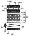
- FIG. 3 illustrates a cross-sectional structure of a display unit according to another exemplary embodiment of the present specification.
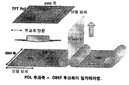
- Figure 4 illustrates the process in the case of attaching the polarizing plate and the luminance-enhanced film with a roll roll.
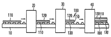
- FIG. 5 is a conceptual diagram illustrating an optical film laminating system according to an exemplary embodiment of the present specification.
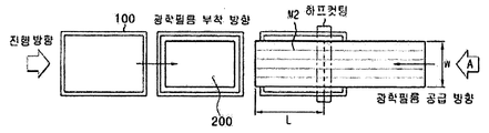
- FIG. 6 is a plan view of a forming unit of an optical film according to a first exemplary embodiment of the present specification.
- FIG. 7 is a cross-sectional view of a forming unit of an optical film according to a first exemplary embodiment of the present specification.
- FIG. 8 is a cross-sectional view of a forming unit of an optical film viewed in a 90 ° rotated direction of the cross-sectional view of FIG.
- FIG. 9 is a plan view of a forming unit of an optical film according to a second exemplary embodiment of the present specification.
- FIG. 10 is a cross-sectional view of a forming unit of an optical film according to a second exemplary embodiment of the present specification.
- optical film 210 brightness enhancement film
- backlight unit 310 light source
- TFT Pol light source side polarizing plate
- POL polarizing plate
- DBEF-P Luminance Enhancement Film with Light Source Side Polarizer
- a step of preparing a panel unit having a light source side polarizing plate on one surface of the panel And attaching the optical film on the light source side polarizing plate by supplying the optical film from the roll on which the optical film is wound to the light source side polarizing plate.
- the display unit manufacturing method includes preparing a panel unit having a light source side polarizing plate on one surface of the panel.
- the screen portion side is opposite to the surface provided with the light source side polarizing plate of the panel.
- the method may further include attaching the polarizing plate so that the transmission axis of the light source side polarizing plate and the transmission axis of the screen side side polarizing plate are perpendicular to each other.
- the display unit manufacturing method may include preparing a panel unit including a screen side polarizer on one surface of the panel and a light source side polarizer on the other surface of the panel.
- the preparing of the panel unit may include forming a screen side polarizer on one surface of the panel and then forming a light source side polarizer on the other surface of the panel; Forming a light source side polarizer on one surface of the panel, and then forming a screen side polarizer on the other surface of the panel; Alternatively, the method may include simultaneously forming the screen side polarizer and the light source side polarizer on one side and the other side of the panel.
- the preparing of the panel unit may include attaching a plate-shaped polarizing plate to one surface of the panel, or attaching the polarizing plate to one surface of the panel by supplying a polarizing plate to one surface of the panel from a roll wound around the polarizing plate.
- the preparing of the panel unit may include attaching a plate-shaped polarizing plate to both sides of the panel, or attaching the polarizing plate to both sides of the panel by supplying polarizing plates to both sides of the panel, respectively, from rolls on which the polarizing plate is wound.
- the preparing of the panel unit may be a step of attaching the polarizing plate to one surface of the panel by supplying the polarizing plate to one surface of the panel from the roll on which the polarizing plate is wound.
- the preparing of the panel unit may include attaching the polarizing plates to both sides of the panel by respectively supplying the polarizing plates from the rolls of the polarizing plates, and attaching the polarizing plates to both sides of the panel, or simultaneously supplying the polarizing plates to one side and the other side of the panels from the rolls of the polarizing plates.
- the polarizing plate may be attached to the same time.
- the preparing of the panel unit may include attaching the polarizing plates to both sides of the panel after supplying or supplying the polarizing plates to both sides of the panel, respectively, from the rolls on which the polarizing plates are wound, or attaching the polarizing plates to one side of the panel from the rolls of the polarizing plates. It may be a step of simultaneously attaching the polarizing plate on both sides of the panel while supplying at the same time or after supplying.
- the preparing of the panel unit may include supplying the panel by transferring the panel in one direction; And attaching the light source side polarizer to one surface of the panel by supplying the light source side polarizer on the panel from the roll of the light source side polarizer.
- the preparing of the panel unit may include supplying and feeding the panel in one direction; Attaching a light source side polarizing plate to one surface of the panel while or after supplying the light source side polarizing plate from the roll on which the light source side polarizing plate is wound; And attaching the screen side polarizer to the other surface of the panel such that the transmission axis of the light source side polarizer and the transmission axis of the screen side polarizer are perpendicular to the other surface of the panel after supplying or supplying the screen side polarizer from the roll on which the screen side polarizer is wound. It may include. If necessary, attaching the screen side polarizer to one surface of the panel and attaching the light source side polarizer to the other surface of the panel may be performed at the same time.
- the preparing of the panel unit may include supplying and feeding the panel in one direction; While supplying or supplying the polarizing plate along the direction parallel or perpendicular to the conveying direction of the panel from the roll on which the screen side polarizing plate is wound, press the screen side polarizing plate on one side of the panel in a direction parallel to the conveying direction of the panel. Doing; And supplying the polarizing plate along a direction perpendicular to the feeding direction of the screen side polarizing plate from the roll wound around the light source side polarizing plate, and then pressing the light source side polarizing plate in a direction parallel to the conveying direction of the panel to the other surface of the panel. Attaching.
- the polarizing plate wound on the roll is wound in the machine direction (MD, Machine direction), and since the polarizing plate is stretched in the machine direction, the machine direction means the absorption axis direction of the polarizing plate.
- the screen side polarizing plate when supplying a polarizing plate to one surface of the panel, when the screen side polarizing plate is supplied along a direction parallel to the conveying direction of the panel from the roll wound the screen side polarizing plate, it is attached to one surface of the panel
- the screen part side polarizing plate has an absorption axis in the direction parallel to the conveyance direction of the said panel.
- the absorption axis of the light source side polarizing plate which is supplied in a direction perpendicular to the supply direction of the screen side polarizing plate and attached to the other surface of the panel is perpendicular to the absorption axis of the screen side polarizing plate, and is supplied in a direction perpendicular to the supply direction of the light source side polarizing plate.
- the transmission axis of the luminance enhancing film attached to the light source side polarizer may be perpendicular to the absorption axis of the light source side polarizer.
- the screen side polarizing plate when supplying a polarizing plate to one surface of the panel, when the screen side polarizing plate is supplied along a direction perpendicular to the conveying direction of the panel from the roll on which the screen side polarizing plate is wound,
- the attached screen portion side polarizing plate has an absorption axis in a direction perpendicular to the conveying direction of the panel.
- the absorption axis of the light source side polarizing plate which is supplied in a direction perpendicular to the supply direction of the screen side polarizing plate and attached to the other surface of the panel is perpendicular to the absorption axis of the screen side polarizing plate, and is supplied in a direction perpendicular to the supply direction of the light source side polarizing plate.
- the transmission axis of the luminance enhancing film attached to the light source side polarizer may be perpendicular to the absorption axis of the light source side polarizer.
- the absorption axes of the two polarizing plates attached to both sides of the panel are perpendicular to each other.
- the transmission axis of the light source side polarizing plate and the transmission axis of the luminance enhancing film on the light source side polarizing plate are parallel to each other.
- the preparing of the panel unit may further include cutting the light source side polarizer and the screen side polarizer according to the size of the panel.
- the light source-side polarizer and the screen-side polarizer may be cut in accordance with the supply direction of the light source-side polarizer and the screen-side polarizer to a length parallel to the transport direction of the panel or a length perpendicular to the transport direction of the panel.
- preparing the panel unit may include: half-cutting the light source-side polarizer and the screen-side polarizer according to the size of the panel; And removing the release paper of the light source side polarizer and the screen side polarizer.
- the half cutting does not cut the release paper, and by cutting the polarizing plate except the release paper, the polarizing plate can be continuously attached to the panel.
- the method of half-cutting is not particularly limited, and a method used in the art may be adopted.
- the half-cutting method may be cut using a knife or may be half-cutted using a laser.
- the preparing of the panel unit may include: half-cutting the polarizing plate before the polarizing plate released from the roll on which the polarizing plate is wound is supplied to both sides of the panel; Removing the release paper of the polarizing plate; And attaching polarizers to both surfaces of the panel by supplying the surfaces to both sides of the panel, respectively.
- the panel may be a liquid crystal panel including two substrates spaced by a spacer and a liquid crystal provided between the two substrates.
- the liquid crystal panel may further include a color filter, a thin film transistor, and the like provided on opposite surfaces of two substrates spaced apart by a spacer.
- the panel may include a color filter provided on one of two opposite surfaces of two substrates spaced by a spacer and a thin film transistor provided on the other side, or the panel may include two substrates spaced by a spacer. It may include a thin film transistor provided on one of the surfaces facing each other and a color filter provided on the thin film transistor.
- the panel When the panel includes a color filter provided on any one of two opposite surfaces of two substrates spaced apart by a spacer and a thin film transistor provided on the other side, a polarizing plate on the screen side is provided on the other surface of the substrate provided with the color filter.
- the light source side polarizer may be provided on the other surface of the substrate on which the thin film transistor is provided.
- the panel may be a light emitting diode (LED) panel or an organic light emitting diode (OLED) panel.
- LED light emitting diode
- OLED organic light emitting diode
- the structure, material, and manufacturing method of the panel are not particularly limited, and structures, materials, and manufacturing methods generally used in the art may be adopted.
- the thickness of the light source-side polarizing plate and the screen-side polarizing plate is not particularly limited, but the thicknesses of the light source-side polarizing plate and the screen-side polarizing plate may be independently 300 ⁇ m or less, and the thickness of the polarizing plate is not particularly limited.
- the thicknesses of the light source-side polarizer and the screen-side polarizer may be 50 ⁇ m or more and 300 ⁇ m or less, and more preferably 100 ⁇ m or more and 250 ⁇ m or less.
- the light source side polarizing plate and the screen side side polarizing plate may include a polarizing film and a protective film provided on both sides of the polarizing film, respectively.
- the light source side polarizer and the screen side polarizer may include polarizing films 6 and protective films 2 and 3 provided on both surfaces of the polarizing film, respectively.
- the light source side polarizing plate and the screen side side polarizing plate 1 are respectively attached to both surfaces of the central polarizing film 6 and the polarizing film 6 via the adhesive layers 4 and 5, and the panel is formed by the pressure sensitive adhesive 7.
- the polarizing plate 1 may be attached to.
- an antireflection layer On the protective film of the screen portion side polarizing plate, one or more layers of an antireflection layer, a low reflection coating layer, a UV absorbing layer, an antistatic coating layer, an antiglare layer, a liquid crystal coating layer, and a hard coating layer may be further provided as necessary.
- an antireflection layer On the protective film of the light source-side polarizing plate, one or more layers of an antireflection layer, a low reflection coating layer, a UV absorbing layer, an antistatic coating layer, an antiglare layer, a liquid crystal coating layer, and a hard coating layer may be further provided as necessary.
- the structure, material, and manufacturing method of the light source side and the screen side side polarizing plate are not particularly limited, and structures, materials, and manufacturing methods generally used in the art may be adopted.
- the manufacturing method of the display unit includes supplying an optical film on the light source side polarizing plate from a roll on which the optical film is wound and attaching the optical film on the light source side polarizing plate.
- the display unit manufacturing method includes attaching the optical film on the light source side polarizing plate while or after supplying the optical film from the roll on which the optical film is wound onto the light source side polarizing plate.
- the optical film is positioned between the light source side polarizing plate and the backlight unit, and is a film for increasing the efficiency of light generated from the backlight unit or supplementing mechanical properties.
- the optical film is attached to the light source side polarizing plate to form a functional layer.
- the type and lamination structure of the optical film are not particularly limited, and for example, at least one of at least one luminance enhancing film, at least one light collecting sheet, and at least one diffusing film may be provided between the light source side polarizing plate and the backlight unit. .
- Attaching the optical film may include attaching one or more optical films on the light source side polarizer. Specifically, attaching the optical film may include attaching a single layer or a multilayer optical film on the polarizing plate.
- Attaching the optical film may include sequentially attaching two or more optical films on the light source side polarizer.
- the optical film may include a brightness enhancing film provided on the light source side polarizing plate.
- the optical film may include a brightness enhancement film provided on the light source side polarizer and a diffusion film provided on the brightness enhancement film.
- the optical film may include a brightness enhancing film provided on the light source side polarizer and a light collecting sheet provided on the brightness enhancing film.
- the optical film may include one or more luminance enhancing films, one or more diffusing films, and one or more light collecting sheets sequentially, alternately, or randomly provided on the light source side polarizer.
- the optical film may include a brightness enhancing film, a diffusion film, two light collecting sheets, and a diffusion film sequentially on the light source side polarizer.
- the optical film 200 includes a luminance enhancing film 210, a diffusion film 220, two light collecting sheets 230 and 235, and a diffusion film 225 on the light source side polarizer 130. ) May be provided sequentially.
- the attaching of the optical film may include attaching the brightness enhancing film to the light source side polarizing plate by supplying the brightness enhancing film to the light source side polarizing plate from the roll on which the brightness enhancement film is wound.
- the attaching of the optical film may include supplying a brightness enhancing film on the light source side polarizing plate from a roll wound around the brightness enhancing film, and supplying the brightness improving film on the light source side polarizing plate, and transmitting the optical axis of the light source side polarizing plate and the brightness enhancement film. Attaching such that the transmission axes are parallel; And supplying the light collecting sheet onto the brightness enhancing film from the roll on which the light collecting sheet is wound, and attaching the light collecting sheet onto the brightness enhancing film.
- the attaching of the optical film may include supplying a brightness enhancing film on the light source side polarizing plate from a roll wound around the brightness enhancing film, and supplying the brightness improving film on the light source side polarizing plate, and transmitting the optical axis of the light source side polarizing plate and the brightness enhancement film. Attaching such that the transmission axes are parallel; And supplying the diffusion film onto the brightness enhancement film from the roll on which the diffusion film is wound, and attaching the diffusion film onto the brightness enhancement film.
- the attaching of the optical film may include supplying a brightness enhancing film on the light source side polarizing plate from a roll wound around the brightness enhancing film, and supplying the brightness improving film on the light source side polarizing plate, and transmitting the optical axis of the light source side polarizing plate and the brightness enhancement film. Attaching such that the transmission axes are parallel; Supplying a diffusion film onto the brightness enhancement film from a roll on which the diffusion film is wound and attaching the diffusion film onto the brightness enhancement film; And supplying the light collecting sheet onto the diffusion film from the roll on which the light collecting sheet is wound, and attaching the light collecting sheet onto the diffusion film.
- the attaching of the optical film may include attaching the optical film on the light source side polarizer by supplying the optical film on the light source side polarizer along a direction perpendicular to the supply direction of the light source side polarizer from the roll on which the optical film is wound. It may include.
- the attaching of the optical film may include transferring the optical film onto the light source side polarizer by supplying the optical film onto the light source side polarizer along a direction perpendicular to the supply direction of the light source side polarizer from the roll on which the optical film is wound. And pressing in a direction parallel to the direction.
- Attaching the optical film may further include cutting the optical film according to the size of the panel.
- the optical film may be cut to a length parallel to the conveying direction of the panel or a length perpendicular to the conveying direction of the panel according to the supply direction of the optical film.
- the attaching of the optical film may include halfcutting the optical film according to the size of each panel; And it may further comprise the step of removing the release paper of the optical film. At this time, the half-cutting does not cut the release paper, and by cutting the optical film except the release paper, the optical film can be continuously attached to the light source side polarizing plate.
- the attaching of the optical film may include halfcutting the optical film before the optical film released from the roll on which the optical film is wound is supplied onto the light source side polarizing plate; Removing the release paper of the optical film; And attaching an optical film by supplying the light source-side polarizing plate.
- the thickness of the optical film to be attached at one time may be more than 1 ⁇ m 700 ⁇ m.
- the thickness of the single-layer optical film to be attached at one time may be more than 1 ⁇ m 150 ⁇ m.
- the thickness of the brightness enhancing film may be 1 ⁇ m or more and 150 ⁇ m or less.
- the brightness enhancement film may be 1 ⁇ m or more and 70 ⁇ m or less.
- the thickness of the multilayer optical film attached at one time may be 20 ⁇ m or more and 700 ⁇ m or less.
- the thickness of the multilayer optical film may be 20 ⁇ m or more and 700 ⁇ m or less.
- the multilayer optical film may have a thickness of 20 ⁇ m or more and 200 ⁇ m or less.
- the method may further include providing a backlight unit on the optical film.
- the backlight unit corresponds to a light source of a liquid crystal display, and the structure and material of the backlight unit are not particularly limited, but a structure and a material generally used in the art may be adopted.
- the backlight unit may use a bulb, a light emitting diode (LED), or an organic light emitting diode (OLED) as a light source, and may further include at least one of a reflector and a light guide for light efficiency. have.
- the present specification provides a panel transfer unit for transferring the panel in either direction; A forming unit of a light source side polarizing plate for forming a light source side polarizing plate on one surface of the panel; A forming unit of the screen side polarizing plate, wherein the screen side polarizing plate is formed on the other surface of the panel such that the transmission axis of the light source side polarizing plate and the transmission axis of the screen side polarizing plate are perpendicular to each other; And an optical film forming unit attaching the optical film on the light source side polarizing plate, wherein the optical film forming unit includes an optical film supply roll for supplying the optical film, cutting means for cutting the optical film, and an optical film on the light source side polarizing plate. It provides an optical film laminating system comprising an optical film attachment means for pressing and attaching the film.
- an optical film laminating system includes a panel transfer unit 10 for transferring a panel; A forming unit 20 of the screen part side polarizing plate for forming the screen part side polarizing plate 120 on one surface of the panel 110; A forming unit 30 of the light source side polarizing plate for forming the light source side polarizing plate 130 on the other surface of the panel; And an optical film forming unit 40 attaching the optical film 200 to the light source side polarizer 130.
- the present specification is a panel transfer unit for transferring a panel; A forming unit of a light source side polarizing plate for forming a light source side polarizing plate on one surface of the panel; A forming unit of the screen side polarizing plate, wherein the screen side polarizing plate is formed on the other surface of the panel such that the transmission axis of the light source side polarizing plate and the transmission axis of the screen side polarizing plate are perpendicular to each other; And an optical film forming unit attaching the optical film on the light source side polarizing plate, wherein the optical film forming unit includes an optical film supply roll for supplying the optical film, cutting means for cutting the optical film, and an optical film on the light source side polarizing plate. It provides an optical film laminating system comprising an optical film attachment means for pressing and attaching the film.
- the optical film laminating system may refer to the description of the above-described display unit manufacturing method.
- the panel transfer unit is a unit for transferring a panel, and includes a conveyor belt for supporting and transporting a panel having a predetermined size, or includes a transport roller for supporting and transporting a panel having a predetermined size while rotating a plurality of rollers. can do.
- the panel conveying unit may have a width equal to or greater than the width of the panel.
- the forming unit of the light source-side polarizing plate may include polarizing plate conveying means for transferring the plate-shaped polarizing plate and polarizing plate attaching means for attaching the plate-shaped polarizing plate to the panel.
- the forming unit of the light source side polarizing plate may include a light source side polarizing plate supply roll for supplying the light source side polarizing plate, cutting means for cutting the light source side polarizing plate, and a light source side polarizing plate attachment means for attaching the light source side polarizing plate to one surface of the panel.
- the cutting means may be half cutting means for cutting the light source side polarizing plate except the release paper, without cutting the release paper.
- the light source-side polarizer may include a release paper remover positioned between the light source-side polarizer supply roll and the light source-side polarizer attachment means to separate the release paper attached to the light source-side polarizer.
- the light source side polarizing plate forming unit may include a light source side polarizing plate supply roll for supplying a light source side polarizing plate in a direction parallel or perpendicular to the conveying direction of the panel, cutting means for cutting the light source side polarizing plate, and a light source side polarizing plate on one surface of the panel. It may include a light source side polarizing plate attachment means for pressing by pressing in a direction parallel to the conveying direction of the panel.
- the forming unit of the light source side polarizing plate may further include a direction changing roll for switching the supply direction of the light source side polarizing plate to face one surface of the panel.
- the light source-side polarizing plate attachment means may include a laminating roll, a laminating drum having a suction hole formed on an outer circumferential surface, or a laminating drum having a suction pad on an outer circumferential surface.
- the light source side polarizing plate attaching means may include a laminating drum having a suction hole formed on an outer circumferential surface or a laminating drum having a suction pad on an outer circumferential surface thereof. Can be.
- the forming unit of the screen side polarizing plate may include a polarizing plate conveying means for transferring the plate-shaped polarizing plate and polarizing plate attachment means for attaching the plate-shaped polarizing plate to the panel.
- the forming unit of the screen side polarizer may include a screen side polarizer supply roll for supplying the screen side polarizer, cutting means for cutting the screen side polarizer, and a screen side polarizer attachment means for attaching the screen side polarizer to the other side of the panel.
- the cutting means may be half cutting means for cutting the screen side polarizer except for the release paper.
- the screen side polarizer When the screen side polarizer includes a release paper provided on the surface in contact with the panel, it may include a release paper remover positioned between the screen side polarizer feed roll and the screen side polarizer attachment means to separate the release paper attached to the screen side polarizer. have.
- the screen unit side polarizing plate forming unit is a screen side side polarizing plate supply roll for supplying a screen side side polarizing plate, cutting means for cutting the screen side side polarizing plate, and the transmission axis of the light source side polarizing plate so that the transmission axis of the screen side side polarizing plate is perpendicular to the other side of the panel.
- a screen side polarizer attachment means for pressing and attaching the screen side polarizer in a direction parallel to the conveying direction of the panel.
- the forming unit of the screen part side polarizing plate may further include a direction changing roll for switching the supply direction of the screen part side polarizing plate to face the other surface of the panel.
- the screen unit side polarizing plate attachment means may include a laminating roll, a laminating drum having a suction hole formed on the outer circumferential surface, or a laminating drum having a suction pad on the outer circumferential surface.
- the screen side side polarizing plate attachment means may include a laminating drum having a suction hole formed on the outer circumferential surface or a laminating drum having a suction pad on the outer circumferential surface. Can be.
- the forming unit of the optical film may include an optical film supply roll for supplying the optical film, cutting means for cutting the optical film, and an optical film attaching means for pressing and attaching the optical film onto the light source side polarizing plate.
- the forming unit of the optical film may include two or more optical film forming units according to the number of optical films.
- the cutting means may be a half cutting means for cutting the optical film except for the release paper without cutting the release paper.
- the optical film may include a release paper remover positioned between the optical film supply roll and the optical film attachment means to separate the release paper attached to the optical film.
- the optical film forming unit includes an optical film supply roll for supplying the optical film along a direction perpendicular to the supply direction of the light source side polarizing plate, cutting means for cutting the optical film, and transfer of the optical film to the light source side polarizing plate. It may include an optical film attachment means for attaching by pressing in a direction parallel to the direction.
- the optical film is supplied along the direction perpendicular to the traveling direction of the panel unit.
- the optical film 200 may be attached onto the polarizing plate. At this time, when the optical film is a transmission axis may be in the direction of M1 shown in FIG.
- the optical film forming unit is optically along the direction perpendicular to the advancing direction of the panel unit as shown in FIGS. 7 and 8. It may include an optical film supply roll 21 for supplying the film 200, a cutting means 25 for cutting the optical film and a laminating drum 23, which is an optical film attachment means for attaching the optical film on the light source side polarizing plate. . As shown in FIGS. 7 and 8, the optical film forming unit may further include direction changing rolls 22 and 27 for switching the supply direction of the optical film to face one surface of the light source side polarizing plate.
- the optical film forming unit as shown in Figures 7 and 8, after half-cutting the optical film provided with a release paper, the optical film 200 'from which the release paper is removed to a light source with a laminating drum 23 Attaching the optical film on the side polarizing plate, the removed release paper (S) can be recovered by the release paper recovery roll 26.
- the optical film is supplied along the direction parallel to the traveling direction of the panel unit.
- the optical film 200 may be attached onto the polarizing plate.
- the optical film is a transmission axis may be in the direction of M2 shown in FIG.
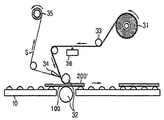
- the optical film forming unit may have an optical film along the direction parallel to the traveling direction of the panel unit as shown in FIG. 10. It may include an optical film supply roll 31 for supplying a 200, a cutting means 36 for cutting the optical film and a laminating drum 32 which is an optical film attachment means for attaching the optical film on the light source side polarizing plate. As shown in FIG. 10, the optical unit forming unit may further include a direction changing roll 33 for switching the supply direction of the optical film to face one surface of the light source side polarizing plate. In addition, the optical film forming unit, as shown in FIG.
- the optical film 200 'with the release paper is removed using a laminating drum 32 to the light source side polarizing plate Attaching the optical film on, the removed release paper (S) can be recovered by the release paper recovery roll 35.
- the forming unit of the optical film may further include a direction changing roll for switching the supply direction of the optical film to face one surface of the light source-side polarizing plate.
- the optical film attaching means may include a laminating roll, a laminating drum having a suction hole formed on an outer circumferential surface, or a laminating drum having a suction pad on an outer circumferential surface.
- the optical film attaching means may include a laminating drum having a suction hole formed on an outer circumferential surface or a laminating drum having a suction pad on an outer circumferential surface.
- the absorption axis of the polarizing plate attached to the opposite side of the panel should be attached so as to be perpendicular to the absorption axis of the polarizing plate attached to one side, a process for rotating the panel is also required.
- the addition of a device for the rotation of the panel or the optical film is required to perform such an additional process, and the addition of such a device leads to an increase in the length of the process line, thereby reducing the space efficiency.
- the display unit manufacturing method of the present specification when attaching the polarizing plate on both sides of the panel, there is no need to turn over or rotate the panel, there is an advantage that the process is simple to reduce the manufacturing time and increase the space efficiency.
- a functional layer such as a light collecting sheet, a light diffusion layer, and a brightness enhancement layer may be provided between the light source side polarizing plate and the backlight unit to efficiently use the light generated by the backlight unit.
- Functional layers such as a light collecting sheet, a light diffusion layer, and a brightness enhancement layer provided between the light source side polarizer and the backlight unit are spaced apart from each other, so that light loss occurs due to a difference in refractive index between air and the functional layer.
- the absorption axis of the light source side polarizing plate and the transmission axis of the luminance enhancement film between the light source side polarizing plate and the backlight unit are provided perpendicular to each other. Should be.
- the absorption axis B of the light source side polarizer 130 is applied.
- the transmission axis (C) of the brightness enhancement film between the light source side polarizing plate and the backlight unit should be provided to be perpendicular to each other.
- the machine direction of the light source-side polarizing plate is the absorption axis
- the machine direction of the luminance-enhancing film is the transmission axis direction.
- the display unit manufacturing method of the present specification when attaching an optical functional film such as a brightness enhancement film on the light source side polarizing plate attached to the panel, the loss of the original fabric of the polarizing plate and the brightness enhancement film without flipping or rotating the panel Can be reduced.
- each transmission axis should be parallel.However, when adding a retardation film between the light source-side polarizer and the brightness enhancement film, the roll-to-roll process is performed without cutting the light source-side polarizer. Although the film can be manufactured, there is a disadvantage in that the manufacturing cost is increased because the retardation film must be additionally provided.
- the display unit manufacturing method of the present specification is a simple process for attaching the brightness enhancement film on the light source side polarizing plate even if the retardation film between the light source side polarizing plate and the brightness enhancement film is not simple and the fabric loss of the optical film is reduced The cost is reduced.
Landscapes
- Physics & Mathematics (AREA)
- Nonlinear Science (AREA)
- Mathematical Physics (AREA)
- Chemical & Material Sciences (AREA)
- Crystallography & Structural Chemistry (AREA)
- General Physics & Mathematics (AREA)
- Optics & Photonics (AREA)
- Polarising Elements (AREA)
Abstract
Description
Claims (18)
- 패널의 일면에 광원측 편광판이 구비된 패널유닛을 준비하는 단계; 및광학필름이 감긴 롤로부터 상기 광학필름을 상기 광원측 편광판 상에 공급하여 상기 광원측 편광판 상에 상기 광학필름을 부착하는 단계를 포함하는 것인 디스플레이 유닛 제조방법.
- 청구항 1에 있어서, 상기 광학필름은 휘도향상필름, 집광시트 및 확산필름 중 적어도 하나를 포함하는 것인 디스플레이 유닛 제조방법.
- 청구항 1에 있어서, 상기 광학필름을 부착하는 단계는 휘도향상필름이 감긴 롤로부터 상기 휘도향상필름을 상기 광원측 편광판 상에 공급하여 광원측 편광판 상에 휘도향상필름을, 상기 광원측 편광판의 투과축과 상기 휘도향상필름의 투과축이 평행하도록, 부착하는 단계를 포함하는 것인 디스플레이 유닛 제조방법.
- 청구항 1에 있어서, 상기 광학필름을 부착하는 단계는 2 이상의 광학필름을 상기 광원측 편광판 상에 순차적으로 부착하는 단계를 포함하는 것인 디스플레이 유닛 제조방법.
- 청구항 1에 있어서, 상기 광학필름을 부착하는 단계는 휘도향상필름이 감긴 롤로부터 휘도향상필름을 상기 광원측 편광판 상에 공급하여 상기 광원측 편광판 상에 휘도향상필름을, 상기 광원측 편광판의 투과축과 휘도향상필름의 투과축이 평행하도록, 부착하는 단계; 및 집광시트가 감긴 롤로부터 상기 집광시트를 상기 휘도향상필름 상에 공급하여 상기 휘도향상필름 상에 상기 집광시트를 부착하는 단계를 포함하는 것인 디스플레이 유닛 제조방법.
- 청구항 1에 있어서, 상기 광원측 편광판이 구비된 패널유닛을 준비하는 단계 전에, 상기 광학필름을 부착하는 단계 전에, 또는 상기 광학필름을 부착하는 단계 후에, 상기 패널의 광원측 편광판이 구비된 면의 반대면에 화면부측 편광판을, 상기 광원측 편광판의 투과축과 상기 화면부측 편광판의 투과축이 수직하도록, 부착하는 단계를 더 포함하는 디스플레이 유닛 제조방법.
- 청구항 1에 있어서, 상기 광학필름을 부착하는 단계 후에, 상기 광학필름 상에 광원을 구비하는 단계를 더 포함하는 디스플레이 유닛 제조방법.
- 청구항 1에 있어서, 상기 패널유닛을 준비하는 단계는 상기 패널의 일면에 판형 편광판을 부착하거나, 편광판이 감긴 롤로부터 편광판을 상기 패널의 일면에 공급하여 상기 패널의 일면에 편광판을 부착하는 단계를 포함하는 것인 디스플레이 유닛 제조방법.
- 청구항 1에 있어서, 상기 패널유닛을 준비하는 단계는,상기 패널을 어느 한 방향으로 이송하여 공급하는 단계; 및상기 광원측 편광판이 감긴 롤로부터 상기 패널 상에 상기 광원측 편광판을 공급하여 상기 패널의 일면에 상기 광원측 편광판을 부착하는 단계를 포함하는 것인 디스플레이 유닛 제조방법.
- 청구항 1에 있어서, 상기 디스플레이 유닛 제조방법은,상기 패널을 어느 한 방향으로 이송하여 공급하는 단계;상기 광원측 편광판이 감긴 롤로부터 상기 광원측 편광판을 공급하여 상기 패널의 일면에 상기 광원측 편광판을 부착하는 단계; 및화면부측 편광판이 감긴 롤로부터 상기 화면부측 편광판을 공급하여 상기 패널의 타면에 상기 화면부측 편광판을, 상기 광원측 편광판의 투과축과 상기 화면부측 편광판의 투과축이 수직하도록, 부착하는 단계를 포함하는 것인 디스플레이 유닛 제조방법.
- 청구항 10에 있어서, 상기 광학필름을 부착하는 단계는 휘도향상필름이 감긴 롤로부터 상기 휘도향상필름을 상기 광원측 편광판 상에 공급하여 상기 광원측 편광판 상에 상기 휘도향상필름을, 상기 광원측 편광판의 투과축과 상기 휘도향상필름의 투과축이 평행하도록, 부착하는 단계를 포함하는 것인 디스플레이 유닛 제조방법.
- 청구항 1에 있어서, 상기 광학필름의 두께는 1㎛ 이상 700㎛ 이하인 것인 디스플레이 유닛 제조방법.
- 패널을 어느 한 방향으로 이송시키는 패널 이송유닛;상기 패널의 일면에 광원측 편광판을 형성하는 광원측 편광판의 형성유닛;상기 패널의 타면에 화면부측 편광판을, 상기 광원측 편광판의 투과축과 상기 화면부측 편광판의 투과축이 수직하도록, 형성하는 화면부측 편광판의 형성유닛; 및상기 광원측 편광판 상에 광학필름을 부착하는 광학필름의 형성유닛을 포함하며,상기 광학필름의 형성유닛은 상기 광학필름을 공급하는 광학필름 공급롤, 광학필름을 자르는 커팅수단 및 상기 광원측 편광판 상에 상기 광학필름을 가압하여 부착하는 광학필름 부착수단을 포함하는 것인 광학 필름 라미네이팅 시스템.
- 청구항 13에 있어서, 상기 화면부측 편광판의 형성유닛 및 광원측 편광판의 형성유닛은 각각 판형 편광판을 이송시키는 편광판 이송수단 및 판형 편광판을 패널에 부착하는 편광판 부착수단을 포함하는 것인 광학 필름 라미네이팅 시스템.
- 청구항 13에 있어서, 상기 화면부측 편광판의 형성유닛은 상기 화면부측 편광판을 공급하는 화면부측 편광판 공급롤, 상기 화면부측 편광판을 자르는 커팅수단 및 상기 패널의 일면에 화면부측 편광판을 가압하여 부착하는 화면부측 편광판 부착수단을 포함하고,상기 광원측 편광판의 형성유닛은 상기 광원측 편광판을 공급하는 광원측 편광판 공급롤, 상기 광원측 편광판을 자르는 커팅수단 및 상기 패널의 타면에 상기 광원측 편광판을 가압하여 부착하는 광원측 편광판 부착수단을 포함하는 것인 광학 필름 라미네이팅 시스템.
- 청구항 13에 있어서, 상기 광원측 편광판의 형성유닛은 상기 패널의 이송방향과 평행하거나 수직한 방향을 따라 상기 광원측 편광판을 공급하는 광원측 편광판 공급롤, 상기 광원측 편광판을 자르는 커팅수단 및 상기 패널의 일면에 상기 광원측 편광판을 부착하는 광원측 편광판 부착수단을 포함하며,상기 화면부측 편광판의 형성유닛은 상기 화면부측 편광판을 공급하는 화면부측 편광판 공급롤, 상기 화면부측 편광판을 자르는 커팅수단 및 상기 광원측 편광판의 투과축과 상기 화면부측 편광판의 투과축이 수직하도록, 패널의 타면에 화면부측 편광판을 부착하는 화면부측 편광판 부착수단을 포함하는 것인 광학 필름 라미네이팅 시스템.
- 청구항 13에 있어서, 상기 광원측 편광판의 형성유닛은 광원측 편광판의 공급방향을 상기 패널의 일면과 대면하도록 전환시키는 방향전환롤을 더 포함하고, 상기 화면부측 편광판의 형성유닛은 상기 화면부측 편광판의 공급방향을 패널의 타면과 대면하도록 전환시키는 방향전환롤을 더 포함하는 것인 광학 필름 라미네이팅 시스템.
- 청구항 15 또는 16에 있어서, 상기 화면부측 편광판의 형성유닛은 상기 화면부측 편광판 공급롤과 상기 화면부측 편광판 부착수단 사이에 위치하여 상기 화면부측 편광판에 부착된 이형지를 분리시키는 이형지 리무버를 더 포함하고,상기 광원측 편광판의 형성유닛은 상기 광원측 편광판 공급롤과 상기 광원측 편광판 부착수단 사이에 위치하여 상기 광원측 편광판에 부착된 이형지를 분리시키는 이형지 리무버를 더 포함하는 것인 광학 필름 라미네이팅 시스템.
Priority Applications (3)
| Application Number | Priority Date | Filing Date | Title |
|---|---|---|---|
| JP2016567221A JP2017534073A (ja) | 2015-04-30 | 2016-04-29 | ディスプレイユニットの製造方法および光学フィルムラミネートシステム |
| CN201680001281.XA CN106415375B (zh) | 2015-04-30 | 2016-04-29 | 显示部件制造方法及光学膜层压系统 |
| US15/303,070 US10324331B2 (en) | 2015-04-30 | 2016-04-29 | Method of manufacturing display unit and system for laminating optical film |
Applications Claiming Priority (4)
| Application Number | Priority Date | Filing Date | Title |
|---|---|---|---|
| KR20150062061 | 2015-04-30 | ||
| KR10-2015-0062061 | 2015-04-30 | ||
| KR10-2016-0052228 | 2016-04-28 | ||
| KR1020160052228A KR101889144B1 (ko) | 2015-04-30 | 2016-04-28 | 디스플레이 유닛 제조방법 및 광학 필름 라미네이팅 시스템 |
Publications (1)
| Publication Number | Publication Date |
|---|---|
| WO2016175598A1 true WO2016175598A1 (ko) | 2016-11-03 |
Family
ID=57199480
Family Applications (1)
| Application Number | Title | Priority Date | Filing Date |
|---|---|---|---|
| PCT/KR2016/004499 Ceased WO2016175598A1 (ko) | 2015-04-30 | 2016-04-29 | 디스플레이 유닛 제조방법 및 광학 필름 라미네이팅 시스템 |
Country Status (1)
| Country | Link |
|---|---|
| WO (1) | WO2016175598A1 (ko) |
Cited By (1)
| Publication number | Priority date | Publication date | Assignee | Title |
|---|---|---|---|---|
| WO2018216096A1 (ja) * | 2017-05-23 | 2018-11-29 | 堺ディスプレイプロダクト株式会社 | 偏光板貼付装置および偏光板貼付方法 |
Citations (5)
| Publication number | Priority date | Publication date | Assignee | Title |
|---|---|---|---|---|
| JP2003315545A (ja) * | 2002-04-24 | 2003-11-06 | Nitto Denko Corp | 光学フィルム、透過型液晶表示装置およびその製造方法 |
| KR20110096766A (ko) * | 2010-02-23 | 2011-08-31 | 엘지디스플레이 주식회사 | 광학 필름, 이의 제조 방법과 이를 적용한 액정 표시 장치 |
| JP2012198318A (ja) * | 2011-03-18 | 2012-10-18 | Sumitomo Chemical Co Ltd | 液晶表示装置の製造装置および製造方法 |
| KR20140051024A (ko) * | 2012-10-22 | 2014-04-30 | 엘지디스플레이 주식회사 | 편광판 제조장치, 편광판 제조방법, 편광판 및 이를 포함하는 디스플레이 장치 |
| KR101495763B1 (ko) * | 2014-02-28 | 2015-02-25 | 주식회사 엘지화학 | 광학 필름 라미네이팅 시스템 및 이를 이용한 디스플레이 유닛 제조방법 |
-
2016
- 2016-04-29 WO PCT/KR2016/004499 patent/WO2016175598A1/ko not_active Ceased
Patent Citations (5)
| Publication number | Priority date | Publication date | Assignee | Title |
|---|---|---|---|---|
| JP2003315545A (ja) * | 2002-04-24 | 2003-11-06 | Nitto Denko Corp | 光学フィルム、透過型液晶表示装置およびその製造方法 |
| KR20110096766A (ko) * | 2010-02-23 | 2011-08-31 | 엘지디스플레이 주식회사 | 광학 필름, 이의 제조 방법과 이를 적용한 액정 표시 장치 |
| JP2012198318A (ja) * | 2011-03-18 | 2012-10-18 | Sumitomo Chemical Co Ltd | 液晶表示装置の製造装置および製造方法 |
| KR20140051024A (ko) * | 2012-10-22 | 2014-04-30 | 엘지디스플레이 주식회사 | 편광판 제조장치, 편광판 제조방법, 편광판 및 이를 포함하는 디스플레이 장치 |
| KR101495763B1 (ko) * | 2014-02-28 | 2015-02-25 | 주식회사 엘지화학 | 광학 필름 라미네이팅 시스템 및 이를 이용한 디스플레이 유닛 제조방법 |
Cited By (1)
| Publication number | Priority date | Publication date | Assignee | Title |
|---|---|---|---|---|
| WO2018216096A1 (ja) * | 2017-05-23 | 2018-11-29 | 堺ディスプレイプロダクト株式会社 | 偏光板貼付装置および偏光板貼付方法 |
Similar Documents
| Publication | Publication Date | Title |
|---|---|---|
| JP2005043384A (ja) | 偏光板貼合方法及び装置 | |
| KR101646479B1 (ko) | 광학 표시 패널의 연속 제조 방법 및 광학 표시 패널의 연속 제조 시스템 | |
| WO2017091031A1 (ko) | 편광자 보호필름, 편광판 및 이를 포함하는 표시장치 | |
| WO2018117384A1 (ko) | 디스플레이 유닛 제조 시스템 | |
| WO2022119124A1 (ko) | 표시장치 | |
| US9550350B2 (en) | Optical display panel production method and optical display panel production system | |
| WO2011090355A2 (ko) | 광배향막 배향 처리용 점착 필름 | |
| TW201350988A (zh) | 光學顯示設備之生產系統 | |
| WO2018028251A1 (zh) | 反光膜表面层、表面保护膜、反光膜及其制造工艺 | |
| WO2022102872A1 (ko) | 표시장치 | |
| WO2019235809A1 (ko) | 적층체 및 이를 포함하는 액정 표시 장치 | |
| WO2020153639A1 (ko) | 액정표시장치 | |
| WO2015129954A1 (ko) | 광학 필름 라미네이팅 시스템 및 이를 이용한 디스플레이 유닛 제조방법 | |
| JP4342851B2 (ja) | 偏光板貼合方法及び装置 | |
| WO2020105953A1 (ko) | 폴더블 백플레이트 필름 및 폴더블 백플레이트 필름의 제조방법 | |
| WO2019235807A1 (ko) | 액정 표시 장치 | |
| WO2016153192A1 (ko) | 필름 터치 센서 제조 방법 및 제조 장치 | |
| WO2019198893A1 (ko) | 백라이트 유닛, 백라이트 유닛을 포함하는 표시 장치 및 표시 장치를 제조하는 방법 | |
| WO2016175598A1 (ko) | 디스플레이 유닛 제조방법 및 광학 필름 라미네이팅 시스템 | |
| CN104903948A (zh) | 光学显示设备的生产系统以及生产方法 | |
| WO2019160328A1 (ko) | 광학필름 라미네이팅 시스템 및 장치 | |
| TW201346391A (zh) | 光學顯示面板之連續製造方法及光學顯示面板之連續製造系統、切換方法及送出裝置 | |
| KR101889144B1 (ko) | 디스플레이 유닛 제조방법 및 광학 필름 라미네이팅 시스템 | |
| WO2019125009A1 (ko) | 디스플레이 유닛 제조방법 및 제조시스템 | |
| WO2016052813A1 (ko) | 광학 필름 및 그 제조방법 |
Legal Events
| Date | Code | Title | Description |
|---|---|---|---|
| WWE | Wipo information: entry into national phase |
Ref document number: 15303070 Country of ref document: US |
|
| ENP | Entry into the national phase |
Ref document number: 2016567221 Country of ref document: JP Kind code of ref document: A |
|
| 121 | Ep: the epo has been informed by wipo that ep was designated in this application |
Ref document number: 16786784 Country of ref document: EP Kind code of ref document: A1 |
|
| NENP | Non-entry into the national phase |
Ref country code: DE |
|
| 122 | Ep: pct application non-entry in european phase |
Ref document number: 16786784 Country of ref document: EP Kind code of ref document: A1 |