WO2016175142A1 - 非接触電圧計測装置 - Google Patents
非接触電圧計測装置 Download PDFInfo
- Publication number
- WO2016175142A1 WO2016175142A1 PCT/JP2016/062723 JP2016062723W WO2016175142A1 WO 2016175142 A1 WO2016175142 A1 WO 2016175142A1 JP 2016062723 W JP2016062723 W JP 2016062723W WO 2016175142 A1 WO2016175142 A1 WO 2016175142A1
- Authority
- WO
- WIPO (PCT)
- Prior art keywords
- voltage
- movable body
- electrode
- displacement
- detection unit
- Prior art date
- Legal status (The legal status is an assumption and is not a legal conclusion. Google has not performed a legal analysis and makes no representation as to the accuracy of the status listed.)
- Ceased
Links
Images




Classifications
-
- G—PHYSICS
- G01—MEASURING; TESTING
- G01R—MEASURING ELECTRIC VARIABLES; MEASURING MAGNETIC VARIABLES
- G01R5/00—Instruments for converting a single current or a single voltage into a mechanical displacement
- G01R5/28—Electrostatic instruments
-
- G—PHYSICS
- G01—MEASURING; TESTING
- G01R—MEASURING ELECTRIC VARIABLES; MEASURING MAGNETIC VARIABLES
- G01R15/00—Details of measuring arrangements of the types provided for in groups G01R17/00 - G01R29/00, G01R33/00 - G01R33/26 or G01R35/00
- G01R15/14—Adaptations providing voltage or current isolation, e.g. for high-voltage or high-current networks
- G01R15/16—Adaptations providing voltage or current isolation, e.g. for high-voltage or high-current networks using capacitive devices
-
- G—PHYSICS
- G01—MEASURING; TESTING
- G01R—MEASURING ELECTRIC VARIABLES; MEASURING MAGNETIC VARIABLES
- G01R15/00—Details of measuring arrangements of the types provided for in groups G01R17/00 - G01R29/00, G01R33/00 - G01R33/26 or G01R35/00
- G01R15/14—Adaptations providing voltage or current isolation, e.g. for high-voltage or high-current networks
- G01R15/16—Adaptations providing voltage or current isolation, e.g. for high-voltage or high-current networks using capacitive devices
- G01R15/165—Adaptations providing voltage or current isolation, e.g. for high-voltage or high-current networks using capacitive devices measuring electrostatic potential, e.g. with electrostatic voltmeters or electrometers, when the design of the sensor is essential
-
- G—PHYSICS
- G01—MEASURING; TESTING
- G01R—MEASURING ELECTRIC VARIABLES; MEASURING MAGNETIC VARIABLES
- G01R19/00—Arrangements for measuring currents or voltages or for indicating presence or sign thereof
- G01R19/0084—Measuring voltage only
-
- G—PHYSICS
- G01—MEASURING; TESTING
- G01R—MEASURING ELECTRIC VARIABLES; MEASURING MAGNETIC VARIABLES
- G01R5/00—Instruments for converting a single current or a single voltage into a mechanical displacement
- G01R5/28—Electrostatic instruments
- G01R5/30—Leaf electrometers
Definitions
- the present invention relates to a non-contact voltage measuring device that measures an AC voltage applied to a conductor without conducting with the conductor.
- Non-contact type voltage measuring device capable of measuring a voltage applied to a measurement object without being connected to the measurement object.
- a Coulomb force acting between an electrode to which a DC high voltage is applied and a detection electrode is detected as a change in weight of the detection electrode, and the change in weight is measured by a scale.
- the present invention has been made in view of such circumstances, and an object thereof is to provide a non-contact voltage measuring apparatus capable of measuring an alternating voltage with high accuracy.
- the non-contact voltage measuring device measures an AC voltage applied to a conductor measurement object without conducting the measurement object.
- This non-contact voltage measuring device is displaced according to a Coulomb force generated between a detection electrode to which a voltage corresponding to the AC voltage is applied, a feedback electrode, and the detection electrode, and a Coulomb force generated between the feedback electrode.
- a movable body of a conductor that is supported in such a manner that an elastic force acts to return to a predetermined neutral position, a displacement detection unit that detects the displacement of the movable body, and a voltage that supplies a voltage to the feedback electrode A supply unit; and a control unit that controls a voltage output from the voltage supply unit so that a detection result of the displacement in the displacement detection unit approaches a predetermined reference value indicating the neutral position.
- the control unit the voltage of the voltage supply unit is controlled so that the displacement of the movable body detected by the displacement detection unit approaches a predetermined reference value indicating the neutral position. By this control, the Coulomb force acting on the movable body approaches zero, and the voltage by the voltage supply unit approaches the voltage of the detection electrode. Therefore, the measured value of the AC voltage is obtained from the voltage of the voltage supply unit.
- the non-contact voltage measuring device may include a first electrostatic coupling electrode that is electrostatically coupled to the measurement object and is electrically connected to the detection electrode. Accordingly, a voltage corresponding to the AC voltage applied to the measurement object is applied to the detection electrode through electrostatic coupling between the measurement object and the first electrostatic coupling electrode.
- the said non-contact voltage measuring device may be provided with the switch part which short-circuits the said detection electrode and the said feedback electrode.
- the control unit turns on the switch unit before measuring the AC voltage, acquires the detection result of the displacement detection unit in the ON state as the reference value, and the switch unit at the time of measuring the AC voltage May be turned off.
- the reference value varies depending on the environment or the like
- the latest appropriate reference value is acquired before the AC voltage is measured, so that the AC voltage measurement accuracy is further increased.
- the non-contact voltage measuring device may include a second electrostatic coupling electrode that is electrostatically coupled to the measurement object in a non-contact manner.
- the voltage supply unit may amplify an input AC signal with a gain corresponding to a gain control signal, and supply a voltage resulting from the amplification to the feedback electrode.
- the control unit is configured to generate an AC signal proportional to the AC voltage of the measurement object based on a signal input from the second electrostatic coupling electrode, and to detect the displacement detection unit.
- a gain control unit that adjusts the gain control signal so that a result approaches the reference value.
- the voltage of the said feedback electrode is produced
- the said displacement detection part may have a magnet and the magnetic detection part which detects the magnetic field by the said magnet.
- One of the magnet and the magnetic detection unit may be provided on the movable body, and the other of the magnet and the magnetic detection unit may be fixed to a base serving as a reference for detecting the displacement.
- the displacement detection unit may output the detection result of the magnetic field in the magnetic detection unit as the detection result of the displacement. Accordingly, the Coulomb force applied to the movable body changes according to the voltage supplied from the voltage supply unit to the feedback electrode, and the change in the Coulomb force becomes the displacement of the movable body, and the displacement is a magnetic field generated by the magnet. Is detected by the magnetic detection unit. Therefore, the magnetic field detected by the magnetic detection unit changes sensitively according to the voltage supplied to the feedback electrode.
- one of the magnet and the magnetic detection unit provided in the movable body may be in a reference position.
- the other of the magnet and the magnetic detection unit provided on the base is perpendicular to a direction in which one of the magnet and the magnetic detection unit is displaced from the reference position along with the displacement of the movable body with respect to the reference position. It may be installed at a position shifted in a different direction.
- the other of the magnet and the magnetic detection unit provided on the base is a direction in which one of the magnet and the magnetic detection unit is displaced from the reference position together with the displacement of the movable body with respect to the reference position. It may be installed at a position shifted in a direction parallel to the direction. Thereby, based on the detection result of the magnetic detection unit, it is possible to distinguish between the case where the movable body is drawn toward the detection electrode side and the case where the movable body is drawn toward the feedback electrode side. Become.
- the non-contact voltage measuring device may include two magnetic detection units.
- One of the magnetic detection units may be installed at a position shifted from the reference position in a first direction that is parallel to a direction in which the movable unit is displaced with respect to the reference position of the magnet.
- the other magnetic detection unit may be installed at a position shifted from the reference position in a second direction opposite to the first direction with respect to the reference position of the magnet.
- a difference between a detected value of the magnetic field of the magnet detected by the one magnetic detection unit and a detected value of the magnetic field of the magnet detected by the other magnetic detection unit approaches a predetermined value.
- the voltage output from the voltage supply unit may be controlled. Thereby, the detection sensitivity of the displacement of the movable body is improved.
- the displacement detection unit is provided on the movable body and has a sharp tip toward the surface of the feedback electrode, or a sharp tip provided on the feedback electrode and sharp toward the surface of the movable body.
- a conductor probe comprising: a voltage source that applies a voltage between the probe and the feedback electrode; and a current detection unit that detects a current flowing from the probe to the feedback electrode by field emission, The current detection result in the current detection unit may be output as the displacement detection result.
- the detection electrode and the feedback electrode may be arranged to face each other. At least a part of the movable body may be located between the detection electrode and the feedback electrode.
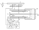
- FIG. 1 is a diagram illustrating an example of a configuration of a non-contact voltage measuring apparatus according to the present embodiment.
- the non-contact voltage measuring apparatus shown in FIG. 1 is an apparatus that measures an AC voltage Vac applied to a conductor measurement object 1 without being connected to the measurement object 1, and includes a conductor movable body 31, a detection electrode 13, and the like.
- the AC voltage Vac is measured using the Coulomb force generated between the movable body 31 and the feedback electrode 14.
- “not conducting” means that the object to be measured and the non-contact voltage measuring device are galvanically insulated, and there is an insulation between them.
- the non-contact voltage measuring device includes a first electrostatic coupling electrode 11, a detection electrode 13, a feedback electrode 14, a movable body 31, a displacement detection unit 40, a voltage supply unit 50, and a control. Part 60 and switch part SW1.
- the measurement object 11 is, for example, a wire connected to the AC power source 4 such as a commercial power system, or a bus bar provided on a switchboard or the like.
- the first electrostatic coupling electrode 11 is electrostatically coupled to the measurement object 1.
- the first electrostatic coupling electrode 11 is formed as a conductive pattern on an insulating substrate 21 (printed substrate, flexible substrate, etc.).
- the first electrostatic coupling electrode 11 and the detection electrode 13 are electrically connected, and are electrically connected by, for example, wiring.
- the detection electrode 13 and the feedback electrode 14 are arranged to face each other and form a parallel plate type capacitor. Similar to the first electrostatic coupling electrode 11, the detection electrode 13 is formed as a conductive pattern on the substrate 23, and the feedback electrode 14 is formed as a conductive pattern on the substrate 24. The substrates 23 and 24 are fixed to the common base 2.
- the movable body 31 is a conductor supported so as to be displaceable in accordance with the Coulomb force generated between the detection electrode 13 and the Coulomb force generated between the movable electrode 31 and the feedback electrode 14, and attempts to return to the predetermined neutral position P. Elastic force works.
- the movable body 31 is a plate-like conductive member having elasticity.
- One end of the movable body 31 is fixed to the base 2, and the detection electrode 13 and the feedback electrode 14 face each other from the fixed end. And stretch in parallel.
- the opposite end of the fixed end is open, and the open end can be displaced in a direction perpendicular to the extending direction.
- the movable body 31 is connected to a reference potential (hereinafter referred to as “ground”) that serves as a reference for measuring the AC voltage Vac.
- ground a reference potential
- the displacement detector 40 detects the displacement of the movable body 31.
- the displacement detection unit 40 includes a magnet 43 and a magnetic detection unit 41.
- the magnet 43 is provided near the open end of the movable body 31 and is displaced together with the movable body 31.
- the magnetic detection unit 41 is a sensor that detects a magnetic field generated by the magnet 43, and is arranged on the substrate 24 in the example of FIG.
- the magnetic detection unit 41 is fixed to the base 2 serving as a reference for displacement of the movable body 31 via the substrate 24.
- the magnetic detection unit 41 has a reference position (position shown in FIG. 1) of the magnet 43 when the open end of the movable body 31 is in the neutral position P (when the potentials of the detection electrode 13 and the feedback electrode 14 are equal). It is installed at a position shifted from the reference position in a direction parallel to the direction in which the movable body 31 is displaced (the direction of the arrow D2 in FIG. 1).
- the voltage supply unit 50 is a circuit that supplies the AC voltage Vs to the feedback electrode 14, and changes the amplitude, frequency, and phase of the AC voltage Vs under the control of the control unit 60.
- Switch part SW1 short-circuits the detection electrode 13 and the feedback electrode 14.
- the switch unit SW1 includes switch elements provided between the detection electrode 13 and the ground and between the feedback electrode 14 and the ground.
- the switch unit SW1 is turned on / off according to the control of the control unit 60.
- the control unit 60 controls the AC voltage Vs output from the voltage supply unit 50 so that the displacement detection result in the displacement detection unit 40 approaches a predetermined reference value indicating the neutral position P.
- the control unit 60 includes, for example, a computer that executes processing according to an instruction code of a program stored in a memory, and a dedicated logic circuit (ASIC or the like) that executes specific processing.
- the control unit 60 turns on the switch unit SW1 before measuring the AC voltage Vac, and the detection result of the displacement detection unit 40 in the on state (the detected value of the magnetic field by the magnetic detection unit 41) is the above reference value. Get as.
- the detection electrode 13, the feedback electrode 14, and the movable body 31 are all at the same potential, and the charges accumulated in these are initialized to zero.
- the movable body 31 is at a predetermined neutral position P. Therefore, the reference value that the control unit 60 acquires from the displacement detection unit 40 when the switch unit SW1 is on indicates that the movable body 31 is in the neutral position P.
- control unit 60 After acquiring the reference value of the displacement detection unit 40, the control unit 60 sets the switch unit SW1 to the off state and starts measuring the AC voltage Vac.
- the control unit 60 sets the AC voltage Vs of the voltage supply unit 50 to a level (for example, zero) that is sufficiently smaller than the AC voltage Vac.
- the electric charge accumulated in the movable body 31 and the detection electrode 13 becomes a maximum value while inverting the polarity between positive and negative every half cycle of the AC voltage Vac.
- the Coulomb force generated between the movable body 31 and the detection electrode 13 is maximized, the movable body 31 is attracted to the detection electrode 13 side, and the detected value of the magnetic field in the magnetic detection unit 41 is the minimum.
- the control unit 60 detects the frequency / phase of the AC voltage Vac based on the detection result of the magnetic detection unit 41 at the start of measurement, and synchronizes the AC voltage Vs with the detected frequency / phase.
- control unit 60 performs an averaging process (low-pass filter process) on the detection result of the magnetic detection unit 41, and adjusts the amplitude of the AC voltage Vs based on the average value of the detection result.
- averaging process low-pass filter process
- the potential difference between the movable body 31 (ground) and the feedback electrode 14 is average compared to the potential difference between the movable body 31 and the detection electrode 13. Becomes smaller.
- the movable body 31 is detected from the neutral position P. It is attracted to the electrode 13 side and displaced in the direction of arrow D1. If it does so, since the magnet 43 will move away from the magnetic detection part 41, the detected value of the magnetic field in the magnetic detection part 41 will become small on average.
- the detected value of the magnetic field in the magnetic detection unit 41 becomes the reference value (the detection value of the magnetic detection unit 41 when the movable body 31 is in the neutral position P). On average, it becomes smaller.
- control unit 60 increases the amplitude of the AC voltage Vs when the average value of the magnetic field detected by the magnetic detection unit 41 is smaller than the reference value, and the amplitude of the AC voltage Vs when the average value is larger than the reference value. Negative feedback control is performed so as to reduce the average value, and the average value approaches the reference value.
- the movable body 31 When the average value of the magnetic field detected by the magnetic detection unit 41 becomes substantially equal to the reference value, the movable body 31 is in the neutral position P, so the Coulomb force on the movable body 31 is almost zero, and the feedback electrode 14 is The potential is almost the same as that of the detection electrode 13. Since the feedback electrode 14 and the detection electrode 13 have the same potential means that almost no current flows through the parasitic capacitor C1 between the first electrostatic coupling electrode 11 and the measurement object 1, The electric potentials of the electric coupling electrode 11 and the measuring object 1 are substantially equal. Therefore, the AC voltage Vs of the voltage supply unit 50 is substantially equal to the AC voltage Vac of the measurement object 1.
- the control unit 60 obtains the measurement result of the amplitude of the AC voltage Vac based on the set value of the amplitude given to adjust the amplitude of the voltage supply unit 50. Can be acquired.
- control part 60 when the control part 60 is comprised with an analog circuit, the voltage measuring device which measures the amplitude of AC voltage Vs is provided separately, and the output is good also as a measurement result of AC voltage Vac.
- a force is generated, and a Coulomb force is generated between the feedback electrode 14 to which the AC voltage Vs is supplied, and a displacement is generated according to the Coulomb force.
- the movable body 31 is subjected to an elastic force for returning to the predetermined neutral position P. Therefore, when the Coulomb force is reduced, the movable body 31 is displaced in a direction approaching the neutral position P.
- the AC voltage Vs of the voltage supply unit 50 is controlled so that the displacement of the movable body 31 detected by the displacement detection unit 40 approaches a predetermined reference value indicating the neutral position P.
- the Coulomb force acting on the movable body 31 approaches zero, and the AC voltage Vs approaches the voltage of the detection electrode 13. Therefore, the measured value of the AC voltage Vac can be obtained from the AC voltage Vs of the voltage supply unit 50.
- the AC voltage Vs is feedback-controlled so that the movable body 31 approaches the neutral position P where the Coulomb force does not work.
- the measurement result is not affected by the relationship between the size and the Coulomb force. Therefore, the measurement accuracy can be greatly improved as compared with the conventional apparatus that measures the Coulomb force acting on the electrode with a scale or the like.
- the switch unit SW1 is turned on before the measurement of the AC voltage Vac, and the detection result of the displacement detection unit 40 in the on state indicates the neutral position P. It is acquired as the reference value shown. Therefore, even when the reference value varies depending on the environment or the like, the latest appropriate reference value can be acquired before the measurement of the AC voltage Vac, so that the measurement accuracy of the AC voltage Vac can be further increased.
- the change in the voltage (V) supplied to the feedback electrode 14 becomes the change in the Coulomb force (F) applied to the movable body 31, and the Coulomb force (F) is changed.
- the change becomes the displacement (D) of the movable body 31, and the displacement (D) is detected as the change (H) of the magnetic field of the magnet 43.
- These voltages (V), Coulomb force (F), displacement (D), and magnetic field (H) have the following general relationship.
- Equation (3) the magnetic field (H) changes very sensitively to the voltage (V) supplied to the feedback electrode 14. Therefore, even if the Coulomb force is very small, the displacement of the movable body 31 can be detected with high sensitivity. Therefore, the accuracy of feedback control is improved, and voltage measurement can be performed with high accuracy.
- the capacitance of a varicap that is a general variable capacitance element is proportional to the inverse of the square root of the voltage applied to the varicap. For this reason, the change in capacitance with respect to the voltage of the varicap is very insensitive compared to the equation (3). Therefore, according to the non-contact voltage measuring apparatus according to the present embodiment, the accuracy and resolution of the voltage measurement can be improved as compared with the method of measuring the AC voltage using the varicap.
- the reference position of the magnet 43 when the open end of the movable body 31 is in the neutral position P (the position shown in FIG. 1) from the reference position.
- the magnetic detection unit 41 is installed at a position shifted in a direction parallel to the direction in which the movable body 31 is displaced (the direction of the arrow D1 in FIG. 1). Thereby, based on the detection result of the magnetic detection unit 41, it is possible to determine whether the movable body 31 is attracted to the detection electrode 13 side or the feedback electrode 14 side with respect to the neutral position P.
- the feedback control by the control unit 60 can be simplified.
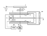
- FIG. 2 is a diagram illustrating an example of the configuration of the non-contact voltage measuring apparatus according to the second embodiment.
- the non-contact voltage measuring device shown in FIG. 2 has a second electrostatic coupling electrode 12 in addition to the same configuration as the non-contact voltage measuring device shown in FIG.
- the control unit 60 includes an AC signal generation unit 61 and a gain control unit 62, and the voltage supply unit 50 includes a variable gain amplifier 51.
- the second electrostatic coupling electrode 12 is electrostatically coupled to the measurement object 1 in a non-contact manner.
- the second electrostatic coupling electrode 12 is formed as a conductive pattern on the common substrate 21 with the first electrostatic coupling electrode 11.
- the voltage supply unit 50 includes a variable gain amplifier 51 that amplifies the AC signal Vg input from the control unit 60 with a gain corresponding to the gain control signal Sc and outputs the amplification result as the AC voltage Vs.
- the AC signal generation unit 61 is a circuit that generates an AC signal Vg proportional to the AC voltage Vac applied to the measurement object 1 based on the signal input from the second electrostatic coupling electrode 12, and is shown in FIG.
- the example includes an operational amplifier 63 and a capacitor Cf.
- the capacitor Cf is connected between the output terminal of the operational amplifier 63 and the inverting input terminal.
- the inverting input terminal of the operational amplifier 63 is connected to the second electrostatic coupling electrode 12, and the non-inverting input terminal is connected to the ground.
- the AC signal Vg is proportional to the AC voltage Vac by a proportional coefficient “C2 / It is a value multiplied by “Cf”.
- the gain control unit 62 adjusts the gain control signal Sc so that the detection result of the displacement detection unit 40 approaches the reference value indicating the neutral position P. That is, the gain control unit 62 obtains the average value of the magnetic field detected by the magnetic detection unit 41 using a low-pass filter or the like, and increases the amplitude of the AC voltage Vs when the average value is smaller than the reference value. When it is larger than the reference value, negative feedback control is performed so as to reduce the amplitude of the AC voltage Vs.
- the AC voltage Vs is generated by amplifying the AC signal Vg proportional to the AC voltage Vac, so that the frequency and phase of the AC voltage Vac and the AC voltage Vs are further increased. It can be matched with high accuracy. Therefore, the AC voltage Vac can be measured with higher accuracy.
- FIG. 3 is a diagram illustrating an example of the configuration of the non-contact voltage measuring apparatus according to the third embodiment.
- the non-contact voltage measuring device shown in FIG. 3 is obtained by replacing the displacement detector 40 in the non-contact voltage measuring device shown in FIG. 1 with a displacement detector 40A, and replacing the controller 60 with a controller 60A.
- the configuration is the same as that of the non-contact voltage measuring apparatus shown in FIG.
- the displacement detector 40A includes a magnet 44 and a magnetic detector 42 in addition to the magnet 43 and the magnetic detector 41 (FIG. 1) already described.
- the magnet 44 is a surface on the opposite side to the surface of the movable body 31 to which the magnet 43 is attached, and is provided near the open end of the movable body 31. Similarly to the magnet 43, the magnet 44 is displaced together with the movable body 31.
- the magnetic detection unit 42 is a sensor that detects a magnetic field generated by the magnet 44, and is mounted on the substrate 23 in the example of FIG. Similarly to the magnetic detection unit 41, the magnetic detection unit 42 is fixed to the base 2 through the substrate 23.
- the direction of the arrow D ⁇ b> 1 in which the magnetic detection unit 42 deviates from the reference position of the magnet 44 is opposite to the direction of the arrow D ⁇ b> 2 in which the magnetic detection unit 41 deviates from the reference position of the magnet 43.
- the control unit 60A supplies voltage so that the difference between the detected value of the magnetic field of the magnet 43 detected by the magnetic detection unit 41 and the detected value of the magnetic field of the magnet 44 detected by the magnetic detection unit 42 approaches a predetermined value.
- the AC voltage Vs output from the unit 50 is controlled. For example, before measuring the AC voltage Vac, the control unit 60A turns on the switch unit SW1 and subtracts the detection value of the magnetic detection unit 42 from the detection value of the magnetic detection unit 41 in the on state. Get the value of. Thereafter, when the AC voltage Vac is measured, the detection value of the magnetic detection unit 42 is subtracted from the detection value of the magnetic detection unit 41, and an average value of the subtraction result is obtained by a low-pass filter or the like.
- the AC voltage Vs of the voltage supply unit 50 is controlled so as to approach a predetermined value.
- the relationship in which the detection value changes in the reverse direction according to the displacement of the movable body 31 decreases.
- the voltage supply unit so that the difference between the detected values approaches a predetermined value (a value indicating that the movable body 31 is in the neutral position P). 50 AC voltages Vs are controlled.
- FIG. 4 is a diagram illustrating a modification of the non-contact voltage measurement device according to the third embodiment.
- the non-contact voltage measuring device shown in FIG. 4 has the already-described second electrostatic coupling electrode 12 (FIG. 2) in addition to the same configuration as the non-contact voltage measuring device shown in FIG. 4 is obtained by replacing the gain control unit 62 of the control unit 60 in FIG. 2 with a gain control unit 62A.
- the gain control unit 62A obtains an average value of the difference between the magnetic field detection values detected by the two magnetic detection units 41 and 42 by a low-pass filter or the like, and the average value is a predetermined value (the movable body 31 is at the neutral position P)
- the gain that determines the amplitude of the AC voltage Vs is subjected to negative feedback control so as to approach the value.
- FIG. 5 is a diagram showing an example of the configuration of a non-contact voltage measuring apparatus according to the fourth embodiment of the present invention.
- the non-contact voltage measuring device shown in FIG. 5 has the same configuration as the non-contact voltage measuring device shown in FIG. 1, but the arrangement of the magnetic detection unit 41 in the displacement detection unit 40 is the same as the non-contact voltage measuring device shown in FIG. Different. That is, in the non-contact voltage measuring device shown in FIG. 5, the direction perpendicular to the direction in which the movable part 31 is displaced from the reference position with respect to the reference position of the magnet 43 when the movable body 31 is in the neutral position P (arrow The magnetic detection unit 41 is installed at a position shifted to D3).
- the magnetic detection unit 41 when the movable body 31 is in the neutral position P, the distance between the magnet 43 and the magnetic detection unit 41 becomes the shortest, and the detected value of the magnetic field by the magnetic detection unit 41 becomes the maximum. . Therefore, even when the width of the displacement of the movable body 31 is relatively large, the magnetic detection unit 41 can be arranged closer to the magnet 43 than the non-contact voltage measurement device shown in FIGS. The position of the movable body 31 in the vicinity can be accurately controlled.
- the displacement of the movable body is detected based on the magnetic field of the magnet.
- the non-contact voltage measuring device according to the present embodiment is movable based on the current flowing due to field emission. Detect body displacement.
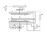
- FIG. 6 is a diagram illustrating an example of the configuration of the non-contact voltage measuring apparatus according to the fifth embodiment.
- the non-contact voltage measuring device shown in FIG. 6 replaces the movable body 31 in the non-contact voltage measuring device shown in FIG. 1 with the movable body 32, replaces the displacement detector 40 with the displacement detector 40B, and controls the controller 60.
- the switch unit SWB is replaced with the switch unit SW1, and the other configuration is the same as that of the non-contact voltage measuring apparatus shown in FIG.
- the movable body 32 is obtained by separating the movable body 31 in FIG. 1 and the like from the ground and connecting it to the displacement detection unit 40B.
- the displacement detection unit 40B includes a probe 47, a voltage source 45, and a current detection unit 46.
- the probe 47 is a conductor having a pointed portion that is pointed toward the surface of the feedback electrode 14, and is fixed to the conductor 32.
- the voltage source 45 applies a constant voltage between the probe 47 and the feedback electrode 14.
- a conductor movable body 32 is used as a path of a current flowing from the voltage source 45 to the probe 47.
- the voltage source 45 supplies a DC voltage so that the probe 47 is negative and the feedback electrode 14 is positive.
- the current detector 46 detects a current (tunnel current) that flows from the probe 47 to the feedback electrode 14 due to field emission.
- the control unit 60B controls the voltage so that the current (tunnel current) detected by the current detection unit 46 of the displacement detection unit 40B approaches a predetermined reference value indicating that the movable body 32 is located at the neutral position P.
- the AC voltage Vs output from the supply unit 50 is controlled.
- the control unit 60B includes a computer and a dedicated logic circuit.
- Switch part SW2 is provided between detection electrode 13 and feedback electrode 14, and short-circuits detection electrode 13 and feedback electrode 14 according to control of control part 60B.
- the control unit 60B turns on the switch unit SW2 before measuring the AC voltage Vac, and acquires the detection result of the current detection unit 46 in the on state as the reference value.
- the switch unit SW2 is turned on, the detection electrode 13 and the feedback electrode 14 are set to the same potential, and the charge accumulated in these is initialized to zero.
- the reference value that the control unit 60B acquires from the current detection unit 46 in the ON state of the switch unit SW2 indicates that the movable body 32 is in the neutral position P.
- the control unit 60B After acquiring the reference value of the displacement detection unit 40, the control unit 60B sets the switch unit SW1 to the OFF state and starts measuring the AC voltage Vac.
- the control unit 60B controls the output voltage of the voltage supply unit 50 so that the current value detected by the current detection unit 46 is equal to the reference value.
- the movable body 32 When the current value detected by the current detector 46 is substantially equal to the reference value, the movable body 32 is in the neutral position P, so the Coulomb force between the detection electrode 13 and the movable body 32 is substantially zero.
- the feedback electrode 14 has substantially the same potential as the detection electrode 13. Therefore, the AC voltage Vs of the voltage supply unit 50 is substantially equal to the AC voltage Vac of the measurement object 1.
- the control unit 60B can acquire the measurement result of the amplitude of the AC voltage Vac based on the waveform of the AC voltage Vs output from the voltage supply unit 50. .
- a voltage measuring device that measures the amplitude of the AC voltage Vs may be separately provided, and the output thereof may be used as the measurement result of the AC voltage Vac.
- a force is generated, and displacement occurs according to the Coulomb force.
- the elastic force for returning to the predetermined neutral position P acts on the movable body 32, displacement occurs in the direction approaching the neutral position P when the Coulomb force becomes small.
- the AC voltage Vs of the voltage supply unit 50 is controlled so that the current generated by the field emission detected by the current detection unit 46 approaches a predetermined reference value when the movable body 32 is positioned at the neutral position P. Is done.
- the Coulomb force acting on the movable body 32 approaches zero, and the AC voltage Vs approaches the voltage of the detection electrode 13. Therefore, the measured value of the AC voltage Vac can be obtained from the AC voltage Vs of the voltage supply unit 50.
- the change in the voltage (V) supplied to the feedback electrode 14 becomes the change in the Coulomb force (F) applied to the movable body 31, and the Coulomb force (F) is changed.
- the change becomes the displacement (D) of the movable body 31, and the field emission current (tunnel current) changes according to the displacement (D). From the equations (1) and (2), the displacement (D), the Coulomb force (F), and the voltage (V) have the following relationship.
- the resolution of the height in the fluctuation of the tunnel current is about 10 ⁇ 10 ⁇ 10 [m] in a general scanning tunneling microscope, even when the displacement of the movable body 31 due to the Coulomb force is very small, the movable body 31. Therefore, it is possible to obtain a highly accurate measurement value of the AC voltage Vac.
- FIG. 7 is a diagram illustrating a modification of the non-contact voltage measuring apparatus according to the fifth embodiment.
- the probe 47 is provided on the movable body 32, but in the modification shown in FIG. 7, the probe 48 is provided on the feedback electrode 14.
- the probe 48 includes a pointed portion that is pointed toward the surface of the movable body 32.
- the voltage source 45 supplies a DC voltage so that the feedback electrode 14 provided with the probe 48 has a negative polarity and the movable body 32 has a positive polarity.
- the present invention is not limited to this example.
- the region facing the detection electrode 13 in the movable body 31 and the region facing the feedback electrode 14 in the movable body 31 may be separated.
- the non-contact voltage measuring device shown in FIG. 8 is obtained by changing the arrangement of the detection electrode 13 and the feedback electrode 14 in the non-contact voltage measuring device shown in FIG. 1 and separating the movable body 31 from the ground. This is the same as the non-contact voltage measuring apparatus shown in FIG. In the non-contact voltage measuring apparatus shown in FIG. 8, the movable body 31 is insulated from the ground when measuring the AC voltage Vac. In this case, a parasitic capacitor C13 formed between the movable body 31 and the detection electrode 13, a parasitic capacitor C14 between the movable body 31 and the feedback electrode 14, and between the first electrostatic coupling electrode 11 and the measurement object 1. Are connected in series with the parasitic capacitor C ⁇ b> 1.
- the electrostatic coupling electrodes (11, 12) and the detection electrode (13) are conductive patterns formed on different substrates (21, 23)
- the present invention is not limited to this.
- the electrostatic coupling electrodes (11, 12) and the detection electrode (13) may be conductive patterns formed at different locations (for example, the front surface and the back surface) on a common substrate, or A part of the common conductive member may be used as the electrostatic coupling electrode (11, 12), and another part may be used as the detection electrode (13).
- the displacement detection unit using the magnet and the magnetic detection unit is taken as an example, but the present invention is not limited to this.
- a displacement detector that detects capacitance due to a change in the distance from the movable body can be used in the present invention.
- the magnet is fixed to the movable body and the magnetic detector is fixed to the base, but the present invention is not limited to this example.
- the magnetic detection unit may be fixed to the movable body, and the magnet may be fixed to the base.
- a cantilever beam having one end fixed and the other end opened is described as an example of a movable body, but the present invention is not limited to this.
- movable bodies having various structures such as a structure in which each corner (each side) of a rectangular plate-shaped conductor is fixed to a base by an elastic material can be used in the present invention.
- DESCRIPTION OF SYMBOLS 1 ... Measuring object, 2 ... Base, 4 ... AC power supply, 11 ... 1st electrostatic coupling electrode, 12 ... 2nd electrostatic coupling electrode, 21, 23, 24 ... Board
Landscapes
- Physics & Mathematics (AREA)
- General Physics & Mathematics (AREA)
- Measuring Instrument Details And Bridges, And Automatic Balancing Devices (AREA)
- Measurement Of Current Or Voltage (AREA)
Abstract
交流電圧を精度よく測定できる非接触電圧測定装置を提供する。交流電圧Vacに応じた電圧が加わる検出電極13と、フィードバック電極14と、検出電極13との間に生じるクーロン力及びフィードバック電極14との間に生じるクーロン力に応じて変位可能に支持されており、所定の中立位置へ復帰させようとする弾性力が働く導体の可動体31と、可動体31の変位を検出する変位検出部40と、フィードバック電極14へ交流電圧Vsを供給する電圧供給部50と、変位検出部40における変位の検出結果が所定の基準値へ近づくように、電圧供給部50から出力される電圧を制御する制御部60とを備える。
Description
本発明は、導体に印加される交流電圧を導体と導通せずに計測する非接触電圧計測装置に関するものである。
測定対象物に印加された電圧を当該測定対象物と導通せずに計測することができる非接触型の電圧計測装置が知られている。例えば下記の特許文献1には、直流高電圧が印加される電極と検出電極との間に作用するクーロン力を、検出電極の重量変化として検出し、その重量変化を秤によって測定するようにした装置が記載されている。
しかしながら、クーロン力は非常に微小な力であるため、検出電極の重量変化を秤によって測定する特許文献1の方法では、電界強度が極めて高くないと(特許文献1の記載例では6~8MV/m)実用的な精度が得られない。従って、例えば商用電源による100~200V程度の交流電圧などをこの方法では精度よく測定できない。
本発明はかかる事情に鑑みてなされたものであり、その目的は、交流電圧を精度よく測定できる非接触電圧測定装置を提供することにある。
本発明に係る非接触電圧測定装置は、導体の測定対象物に印加される交流電圧を前記測定対象物と導通せずに計測を行うものである。この非接触電圧計測装置は、前記交流電圧に応じた電圧が加わる検出電極と、フィードバック電極と、前記検出電極との間に生じるクーロン力及び前記フィードバック電極との間に生じるクーロン力に応じて変位可能に支持されており、所定の中立位置へ復帰させようとする弾性力が働く導体の可動体と、前記可動体の前記変位を検出する変位検出部と、前記フィードバック電極へ電圧を供給する電圧供給部と、前記変位検出部における前記変位の検出結果が前記中立位置を示す所定の基準値へ近づくように、前記電圧供給部から出力される電圧を制御する制御部とを備える。
上記の構成によれば、前記可動体には、前記測定対象物の前記交流電圧に応じた電圧が加わる前記検出電極との間にクーロン力が生じるとともに、前記電圧供給部によって電圧が供給される前記フィードバック電極との間にクーロン力が生じ、それらのクーロン力に応じて変位が生じる。また、前記可動体には、前記中立位置へ復帰させようとする弾性力が働くため、これらのクーロン力が小さくなると、前記中立位置へ近づく方向に変位が生じる。前記制御部では、前記変位検出部において検出される前記可動体の変位が前記中立位置を示す所定の基準値へ近づくように、前記電圧供給部の電圧が制御される。この制御によって、前記可動体に働くクーロン力がゼロに近づき、前記電圧供給部による電圧は前記検出電極の電圧に近づく。従って、前記電圧供給部の電圧から、前記交流電圧の測定値が得られる。
好適に、上記非接触電圧測定装置は、前記測定対象物と静電結合し、前記検出電極と導通する第1静電結合電極を備えてよい。
これにより、前記測定対象物と前記第1静電結合電極との静電結合を通じて、前記測定対象物に印加される前記交流電圧に応じた電圧が前記検出電極に加わる。
これにより、前記測定対象物と前記第1静電結合電極との静電結合を通じて、前記測定対象物に印加される前記交流電圧に応じた電圧が前記検出電極に加わる。
好適に、上記非接触電圧測定装置は、前記検出電極と前記フィードバック電極とを短絡するスイッチ部を備えてよい。前記制御部は、前記交流電圧の測定を行う前に前記スイッチ部をオン状態とし、当該オン状態における前記変位検出部の検出結果を前記基準値として取得し、前記交流電圧の測定時に前記スイッチ部をオフ状態としてよい。
これにより、環境等に応じて前記基準値にばらつきが生じる場合でも、交流電圧の測定を行う前に最新の適切な基準値が取得されるため、交流電圧の測定精度が更に高まる。
これにより、環境等に応じて前記基準値にばらつきが生じる場合でも、交流電圧の測定を行う前に最新の適切な基準値が取得されるため、交流電圧の測定精度が更に高まる。
好適に、上記非接触電圧測定装置は、前記測定対象物と非接触で静電結合する第2静電結合電極を備えてよい。前記電圧供給部は、入力される交流信号をゲイン制御信号に応じたゲインで増幅し、当該増幅結果の電圧を前記フィードバック電極に供給してよい。前記制御部は、前記第2静電結合電極から入力される信号に基づいて、前記測定対象物の前記交流電圧に比例した前記交流信号を生成する交流信号生成部と、前記変位検出部の検出結果が前記基準値へ近づくように前記ゲイン制御信号を調節するゲイン制御部とを有してよい。
上記の構成によれば、前記測定対象物の前記交流電圧に比例し交流信号を増幅することにより、前記フィードバック電極の電圧が生成される。そのため、前記交流電圧と前記フィードバック電極の電圧とが精度よく一致するようになる。
上記の構成によれば、前記測定対象物の前記交流電圧に比例し交流信号を増幅することにより、前記フィードバック電極の電圧が生成される。そのため、前記交流電圧と前記フィードバック電極の電圧とが精度よく一致するようになる。
好適に、前記変位検出部は、磁石と、前記磁石による磁界を検出する磁気検出部とを有してよい。前記磁石及び前記磁気検出部の一方が、前記可動体に設けられ、前記磁石及び前記磁気検出部の他方が、前記変位の検出の基準となる基台に固定されてよい。前記変位検出部は、前記磁気検出部における前記磁界の検出結果を前記変位の検出結果として出力してよい。
これにより、前記電圧供給部が前記フィードバック電極に供給する電圧に応じて、前記可動体に加わるクーロン力が変化し、前記クーロン力の変化が前記可動体の変位となり、当該変位が前記磁石による磁界の変化としてとして前記磁気検出部に検出される。そのため、前記フィードバック電極に供給する電圧に応じて、前記磁気検出部に検出される前記磁界が敏感に変化する。
これにより、前記電圧供給部が前記フィードバック電極に供給する電圧に応じて、前記可動体に加わるクーロン力が変化し、前記クーロン力の変化が前記可動体の変位となり、当該変位が前記磁石による磁界の変化としてとして前記磁気検出部に検出される。そのため、前記フィードバック電極に供給する電圧に応じて、前記磁気検出部に検出される前記磁界が敏感に変化する。
好適に、前記可動体が前記中立位置にある場合、前記可動体に設けられた前記磁石及び前記磁気検出部の一方が基準位置にあってよい。前記基台に設けられた前記磁石及び前記磁気検出部の他方は、前記基準位置に対して、前記可動体の変位とともに前記磁石及び前記磁気検出部の一方が前記基準位置から変位する方向と垂直な方向へずれた位置に設置されてよい。
これにより、前記可動体が前記中立位置にある場合に前記磁石と前記磁気検出部との距離が短くなり、前記磁気検出部による磁界の検出値が大きくなる。
これにより、前記可動体が前記中立位置にある場合に前記磁石と前記磁気検出部との距離が短くなり、前記磁気検出部による磁界の検出値が大きくなる。
或いは、前記基台に設けられた前記磁石及び前記磁気検出部の他方は、前記基準位置に対して、前記可動体の変位とともに前記磁石及び前記磁気検出部の一方が前記基準位置から変位する方向と平行な方向へずれた位置に設置されてもよい。
これにより、前記磁気検出部の検出結果に基づいて、前記可動体が前記中立位置に対して前記検出電極側に引き寄せられている場合と前記フィードバック電極側に引き寄せられている場合とが判別可能となる。
これにより、前記磁気検出部の検出結果に基づいて、前記可動体が前記中立位置に対して前記検出電極側に引き寄せられている場合と前記フィードバック電極側に引き寄せられている場合とが判別可能となる。
好適に、上記非接触電圧測定装置は、2つの前記磁気検出部を備えてよい。一方の前記磁気検出部は、前記磁石の前記基準位置に対して、前記基準位置から前記可動部が変位する方向と平行な方向である第1方向へずれた位置に設置されてよい。他方の前記磁気検出部は、前記磁石の前記基準位置に対して、前記基準位置から前記第1方向と逆の第2方向へずれた位置に設置されてよい。前記制御部は、前記一方の前記磁気検出部において検出された前記磁石の磁界の検出値と前記他方の磁気検出部において検出された前記磁石の磁界の検出値との差が所定の値へ近づくように、前記電圧供給部から出力される電圧を制御してよい。
これにより前記可動体の変位の検出感度が向上する。
これにより前記可動体の変位の検出感度が向上する。
好適に、前記変位検出部は、前記可動体に設けられ、前記フィードバック電極の表面に向かって尖った尖端部、又は、前記フィードバック電極に設けられ、前記可動体の表面に向かって尖った尖端部を備える導体のプローブと、前記プローブと前記フィードバック電極との間に電圧を加える電圧源と、前記プローブから前記フィードバック電極へ電界放出により流れる電流を検出する電流検出部とを有してよく、前記電流検出部における前記電流の検出結果を前記変位の検出結果として出力してよい。
好適に、前記検出電極と前記フィードバック電極とが対向して配置されてよい。前記可動体の少なくとも一部が前記検出電極と前記フィードバック電極との間に挟まれて位置してよい。
本発明によれば、測定対象物と導通せずに交流電圧を精度よく測定できる。
<第1の実施形態>
以下、図面を参照して、本発明の第1の実施形態に係る非接触電圧測定装置を説明する。
図1は、本実施形態に係る非接触電圧測定装置の構成の一例を示す図である。図1に示す非接触電圧測定装置は、導体の測定対象物1に印加される交流電圧Vacを測定対象物1と導通せずに計測する装置であり、導体の可動体31と検出電極13との間に生じるクーロン力、及び、可動体31とフィードバック電極14との間に生じるクーロン力を利用して交流電圧Vacの計測を行う。なお、ここで「導通せず」とは、測定対象物と非接触電圧測定装置とが直流的に絶縁されていることを意味しており、両者の間に絶縁物が介在している場合や、空間を隔て両者が分離している場合を含む。図1の例において、非接触電圧測定装置は、第1静電結合電極11と、検出電極13と、フィードバック電極14と、可動体31と、変位検出部40と、電圧供給部50と、制御部60と、スイッチ部SW1とを有する。
以下、図面を参照して、本発明の第1の実施形態に係る非接触電圧測定装置を説明する。
図1は、本実施形態に係る非接触電圧測定装置の構成の一例を示す図である。図1に示す非接触電圧測定装置は、導体の測定対象物1に印加される交流電圧Vacを測定対象物1と導通せずに計測する装置であり、導体の可動体31と検出電極13との間に生じるクーロン力、及び、可動体31とフィードバック電極14との間に生じるクーロン力を利用して交流電圧Vacの計測を行う。なお、ここで「導通せず」とは、測定対象物と非接触電圧測定装置とが直流的に絶縁されていることを意味しており、両者の間に絶縁物が介在している場合や、空間を隔て両者が分離している場合を含む。図1の例において、非接触電圧測定装置は、第1静電結合電極11と、検出電極13と、フィードバック電極14と、可動体31と、変位検出部40と、電圧供給部50と、制御部60と、スイッチ部SW1とを有する。
測定対象物11は、例えば商用電力系統などの交流電源4につながる電線や、配電盤等に設けられたバスバーである。第1静電結合電極11は、この測定対象物1と静電結合する。第1静電結合電極11は、例えば、絶縁体の基板21(プリント基板、フレキシブル基板など)に導電パターンとして形成される。第1静電結合電極11と検出電極13は導通しており、例えば配線によって電気的に接続される。
検出電極13とフィードバック電極14は、互いに対向して配置されており、平行板型のキャパシタを形成する。第1静電結合電極11と同様に、検出電極13は基板23上に導電パターンとして形成され、フィードバック電極14は基板24上に導電パターンとして形成される。基板23,24は、共通の基台2に固定される。
可動体31は、検出電極13との間に生じるクーロン力及びフィードバック電極14との間に生じるクーロン力に応じて変位可能に支持された導体であり、所定の中立位置Pへ復帰させようとする弾性力が働く。図1の例において、可動体31は弾性を備えた板状の導電部材であり、片方の端部が基台2に固定され、当該固定端から検出電極13及びフィードバック電極14の対向面に対して平行に延伸する。当該固定端の反対側の端部は開放されており、当該開放端が延伸方向に対して垂直な方向に変位可能となっている。可動体31は、交流電圧Vacの測定の基準となる基準電位(以下、「グランド」と記す。)に接続される。
変位検出部40は、可動体31の変位を検出する。図1の例において、変位検出部40は磁石43と磁気検出部41を備える。磁石43は可動体31の開放端の近くに設けられており、可動体31と共に変位する。磁気検出部41は、磁石43による磁界を検出するセンサであり、図1の例では基板24に配置される。磁気検出部41は、可動体31の変位の基準となる基台2に基板24を介して固定される。
磁気検出部41は、可動体31の開放端が中立位置Pにある場合(検出電極13とフィードバック電極14の電位が等しい場合)における磁石43の基準位置(図1に示す位置)に対して、当該基準位置から可動体31が変位する方向と平行な方向(図1における矢印D2の方向)へずれた位置に設置される。
電圧供給部50は、フィードバック電極14へ交流電圧Vsを供給する回路であり、制御部60の制御に従って交流電圧Vsの振幅や周波数、位相を変化させる。
スイッチ部SW1は、検出電極13とフィードバック電極14を短絡する。図1の例において、スイッチ部SW1は、検出電極13とグランドとの間及びフィードバック電極14とグランドとの間に設けられたスイッチ素子をそれぞれ有する。スイッチ部SW1は、制御部60の制御に従ってオンオフする。
制御部60は、変位検出部40における変位の検出結果が中立位置Pを示す所定の基準値へ近づくように、電圧供給部50から出力される交流電圧Vsを制御する。制御部60は、例えばメモリに格納されるプログラムの命令コードに従って処理を実行するコンピュータや、特定の処理を実行する専用のロジック回路(ASIC等)を含んで構成される。
ここで、上述した構成を有する図1に示す非接触電圧測定装置の動作を説明する。
まず制御部60は、交流電圧Vacの測定を行う前にスイッチ部SW1をオン状態とし、当該オン状態における変位検出部40の検出結果(磁気検出部41による磁界の検出値)を上記の基準値として取得する。スイッチ部SW1をオン状態にすると、検出電極13、フィードバック電極14及び可動体31が全て同電位となり、これらに蓄積される電荷がゼロに初期化される。この場合、可動体31にはクーロン力が作用しないため、可動体31は所定の中立位置Pにある。従って、スイッチ部SW1のオン状態において制御部60が変位検出部40から取得する基準値は、可動体31が中立位置Pにあることを示す。
制御部60は、変位検出部40の基準値を取得した後、スイッチ部SW1をオフ状態に設定し、交流電圧Vacの測定を開始する。
測定を開始する時、制御部60は、電圧供給部50の交流電圧Vsを交流電圧Vacに比べて十分に小さいレベル(例えばゼロ)に設定する。この場合、可動体31と検出電極13に蓄積される電荷は、交流電圧Vacの2分の1周期ごとに極性を正負に反転させながら最大値となる。電荷が最大値になるとき、可動体31と検出電極13との間に生じるクーロン力が最大となり、可動体31が検出電極13側に引き寄せられ、磁気検出部41における磁界の検出値は最小となる。従って、磁気検出部41の検出結果は、交流電圧Vacの2分の1周期で振動する。そこで制御部60は、測定開始時の磁気検出部41の検出結果に基づいて、交流電圧Vacの周波数・位相を検出し、検出した周波数・位相に交流電圧Vsを同期させる。
次に制御部60は、磁気検出部41の検出結果に対して平均化処理(ローパスフィルタ処理)を施し、検出結果の平均値に基づいて交流電圧Vsの振幅を調節する。
電圧供給部50の交流電圧Vsの振幅が交流電圧Vacに比べて小さいと、可動体31(グランド)とフィードバック電極14との電位差が、可動体31と検出電極13との電位差に比べて平均的に小さくなる。この場合、可動体31とフィードバック電極14との間に生じるクーロン力が、可動体31と検出電極13との間に生じるクーロン力より平均的に小さくなるため、可動体31は中立位置Pより検出電極13側に引き寄せられて、矢印D1の方向に変位する。そうすると、磁石43が磁気検出部41から遠ざかるため、磁気検出部41における磁界の検出値は平均的に小さくなる。すなわち、交流電圧Vsの振幅が交流電圧Vacに比べて小さい場合、磁気検出部41における磁界の検出値が基準値(可動体31が中立位置Pにある場合の磁気検出部41の検出値)に比べて平均的に小さくなる。
他方、電圧供給部50の交流電圧Vsの振幅が交流電圧Vacに比べて大きい場合は、上記と逆に、磁気検出部41における磁界の検出値が基準値に比べて平均的に大きくなる。
従って、制御部60は、磁気検出部41において検出される磁界の平均値が基準値より小さい場合は交流電圧Vsの振幅を増大させ、当該平均値が基準値より大きい場合は交流電圧Vsの振幅を減少させるように負帰還制御を行い、当該平均値を基準値へ近づける。
磁気検出部41において検出される磁界の平均値が基準値とほぼ等しくなると、可動体31は中立位置Pにあるため、可動体31へのクーロン力はほぼゼロになっており、フィードバック電極14は検出電極13とほぼ同電位になる。フィードバック電極14と検出電極13が同電位になるということは、第1静電結合電極11と測定対象物1との間の寄生キャパシタC1に電流がほとんど流れないことを意味するため、第1静電結合電極11と測定対象物1の電位はほぼ等しくなっている。従って、電圧供給部50の交流電圧Vsは測定対象物1の交流電圧Vacとほぼ等しくなる。
交流電圧Vsが交流電圧Vacとほぼ等しくなるため、例えば制御部60は、電圧供給部50の振幅を調節するために与えた振幅の設定値などに基づいて、交流電圧Vacの振幅の測定結果を取得することができる。
なお、制御部60がアナログ回路によって構成される場合は、交流電圧Vsの振幅を測定する電圧測定器を別途設けて、その出力を交流電圧Vacの測定結果としてもよい。
以上説明したように、本実施形態に係る非接触電圧測定装置によれば、導体の可動体31には、測定対象物1の交流電圧Vacに応じた電圧が加わる検出電極13との間にクーロン力が生じるとともに、交流電圧Vsが供給されるフィードバック電極14との間にクーロン力が生じ、それらのクーロン力に応じて変位が生じる。また、可動体31には、所定の中立位置Pへ復帰させようとする弾性力が働くため、クーロン力が小さくなると中立位置Pへ近づく方向に変位が生じる。制御部60では、変位検出部40において検出される可動体31の変位が中立位置Pを示す所定の基準値へ近づくように、電圧供給部50の交流電圧Vsが制御される。この制御によって、可動体31に働くクーロン力がゼロに近づき、交流電圧Vsは検出電極13の電圧に近づく。従って、電圧供給部50の交流電圧Vsから、交流電圧Vacの測定値を得ることができる。
また、本実施形態に係る非接触電圧測定装置では、可動体31がクーロン力の働かない中立位置Pへ近づくように交流電圧Vsがフィードバック制御されることから、可動体31の変位に要する力の大きさとクーロン力との関係に測定結果が影響を受けなくなる。そのため、電極に作用するクーロン力を秤などによって測定する従来の装置に比べて大幅に測定精度を向上できる。
また、クーロン力が微小であっても、可動体31の弾性力を適宜設定することによって十分な変位量を得ることが可能であるため、従来の装置に比べて低い電圧を精度よく測定することができる。
また、本実施形態に係る非接触電圧測定装置によれば、交流電圧Vacの測定を行う前にスイッチ部SW1がオン状態とされ、当該オン状態における変位検出部40の検出結果が中立位置Pを示す基準値として取得される。
そのため、環境等に応じて基準値にばらつきが生じる場合でも、交流電圧Vacの測定を行う前に最新の適切な基準値を取得できるため、交流電圧Vacの測定精度を更に高めることができる。
そのため、環境等に応じて基準値にばらつきが生じる場合でも、交流電圧Vacの測定を行う前に最新の適切な基準値を取得できるため、交流電圧Vacの測定精度を更に高めることができる。
また、本実施形態に係る非接触電圧測定装置によれば、フィードバック電極14に供給する電圧(V)の変化が、可動体31に加わるクーロン力(F)の変化となり、クーロン力(F)の変化が可動体31の変位(D)となり、その変位(D)が磁石43の磁界の変化(H)としてとして検出される。これらの電圧(V),クーロン力(F),変位(D),磁界(H)は、概ね次のような関係を持つ。
F ∝ V2 …(1)
D ∝ F …(2)
H ∝ 1/D2 ∝ 1/V4 …(3)
D ∝ F …(2)
H ∝ 1/D2 ∝ 1/V4 …(3)
式(3)から分かるように、フィードバック電極14に供給する電圧(V)に対して磁界(H)は非常に敏感に変化する。従って、クーロン力が微小であっても、可動体31の変位を感度よく検出できる。そのため、フィードバック制御の精度が向上し、電圧測定を精度よく行うことができる。
例えば、一般的な可変容量素子であるバリキャップの静電容量は、バリキャップに与える電圧の平方根の逆数に比例する。そのため、バリキャップの電圧に対する静電容量の変化は、式(3)などに比べて非常に鈍感である。従って、本実施形態に係る非接触電圧測定装置によれば、バリキャップを用いて交流電圧の測定を行う方法に比べて、電圧測定の精度や分解能を高めることができる。
また、本実施形態に係る非接触電圧測定装置によれば、可動体31の開放端が中立位置Pにある場合における磁石43の基準位置(図1に示す位置)に対して、当該基準位置から可動体31が変位する方向と平行な方向(図1における矢印D1の方向)へずれた位置に磁気検出部41が設置される。これにより、磁気検出部41の検出結果に基づいて、可動体31が中立位置Pに対して検出電極13側に引き寄せられている場合とフィードバック電極14側に引き寄せられている場合とを判別できるため、制御部60によるフィードバック制御を簡易化できる。
<第2の実施形態>
次に、本発明の第2の実施形態について説明する。
次に、本発明の第2の実施形態について説明する。
図2は、第2の実施形態に係る非接触電圧測定装置の構成の一例を示す図である。
図2に示す非接触電圧測定装置は、図1に示す非接触電圧測定装置と同様な構成に加えて、第2静電結合電極12を有する。また、制御部60は交流信号生成部61とゲイン制御部62を含み、電圧供給部50は可変ゲインアンプ51を含む。
図2に示す非接触電圧測定装置は、図1に示す非接触電圧測定装置と同様な構成に加えて、第2静電結合電極12を有する。また、制御部60は交流信号生成部61とゲイン制御部62を含み、電圧供給部50は可変ゲインアンプ51を含む。
第2静電結合電極12は、第1静電結合電極11と同様に、測定対象物1と非接触で静電結合する。図2の例において、第2静電結合電極12は、第1静電結合電極11と共通の基板21に導電パターンとして形成される。
電圧供給部50は、制御部60から入力される交流信号Vgをゲイン制御信号Scに応じたゲインで増幅し、当該増幅結果を交流電圧Vsとして出力する可変ゲインアンプ51を有する。
交流信号生成部61は、第2静電結合電極12から入力される信号に基づいて、測定対象物1に印加される交流電圧Vacに比例した交流信号Vgを生成する回路であり、図2の例では、オペアンプ63とキャパシタCfを含む。キャパシタCfは、オペアンプ63の出力端子と反転入力端子との間に接続される。オペアンプ63の反転入力端子は第2静電結合電極12に接続され、非反転入力端子はグランドに接続される。第2静電結合電極12と測定対象物1との間の寄生容量を「C2」、キャパシタCfの静電容量を「Cf」とすると、交流信号Vgは、交流電圧Vacに比例係数「C2/Cf」を乗じた値となる。
ゲイン制御部62は、変位検出部40の検出結果が中立位置Pを示す基準値へ近づくようにゲイン制御信号Scを調節する。すなわち、ゲイン制御部62は、磁気検出部41において検出される磁界の平均値をローパスフィルタなどによって求め、当該平均値が基準値より小さい場合は交流電圧Vsの振幅を増大させ、当該平均値が基準値より大きい場合は交流電圧Vsの振幅を減少させるように負帰還制御を行う。
本実施形態に係る非接触電圧測定装置によれば、交流電圧Vacに比例した交流信号Vgを増幅することにより交流電圧Vsが生成されるため、交流電圧Vacと交流電圧Vsの周波数及び位相をより精度よく一致させることができる。従って、更に精度よく交流電圧Vacを測定できる。
<第3の実施形態>
次に、本発明の第3の実施形態を説明する。
次に、本発明の第3の実施形態を説明する。
図3は、第3の実施形態に係る非接触電圧測定装置の構成の一例を示す図である。
図3に示す非接触電圧測定装置は、図1に示す非接触電圧測定装置における変位検出部40を変位検出部40Aに置換し、制御部60を制御部60Aに置換したものであり、他の構成は図1に示す非接触電圧測定装置と同じである。
図3に示す非接触電圧測定装置は、図1に示す非接触電圧測定装置における変位検出部40を変位検出部40Aに置換し、制御部60を制御部60Aに置換したものであり、他の構成は図1に示す非接触電圧測定装置と同じである。
変位検出部40Aは、既に説明した磁石43及び磁気検出部41(図1)に加えて、磁石44及び磁気検出部42を有する。
磁石44は、磁石43が取り付けられた可動体31の面に対して反対側の面であって、可動体31の開放端の近くに設けられている。磁石44も磁石43と同様、可動体31と共に変位する。
磁気検出部42は、磁石44による磁界を検出するセンサであり、図2の例では基板23に実装配置される。磁気検出部42も磁気検出部41と同様、基台2に基板23を介して固定される。
磁気検出部42は、磁石44による磁界を検出するセンサであり、図2の例では基板23に実装配置される。磁気検出部42も磁気検出部41と同様、基台2に基板23を介して固定される。
磁気検出部42は、可動体31の開放端が中立位置Pにある場合における磁石44の基準位置(図3に示す位置)に対して、当該基準位置から可動体31が変位する矢印D1の方向へずれた位置に設置される。磁気検出部42が磁石44の基準位置からずれる矢印D1の方向は、磁気検出部41が磁石43の基準位置からずれる矢印D2の方向の逆である。
制御部60Aは、磁気検出部41において検出された磁石43の磁界の検出値と磁気検出部42において検出された磁石44の磁界の検出値との差が所定の値へ近づくように、電圧供給部50から出力される交流電圧Vsを制御する。例えば制御部60Aは、交流電圧Vacの計測を行う前において、スイッチ部SW1をオン状態とし、当該オン状態における磁気検出部41の検出値から磁気検出部42の検出値を減算した結果を上記所定の値として取得する。その後、交流電圧Vacの計測を行う場合には、磁気検出部41の検出値から磁気検出部42の検出値を減算し、その減算結果の平均値をローパスフィルタなどにより求め、当該平均値が上記所定の値へ近づくように電圧供給部50の交流電圧Vsを制御する。
このように、本実施形態に係る非接触電圧測定装置によれば、可動体31の変位に応じて検出値が逆方向に変化する関係(一方の検出値が増大すると他方の検出値が減少する関係)にある2つの磁気検出部(41,42)を用いて、それらの検出値の差が所定の値(可動体31が中立位置Pにあることを示す値)へ近づくように電圧供給部50の交流電圧Vsが制御される。
これにより、可動体31の変位を更に感度良く検出できるため、交流電圧Vacの測定を高い分解能で精度良く行くことができる。
これにより、可動体31の変位を更に感度良く検出できるため、交流電圧Vacの測定を高い分解能で精度良く行くことができる。
図4は、第3の実施形態に係る非接触電圧測定装置の一変形例を示す図である。
図4に示す非接触電圧測定装置は、図3に示す非接触電圧測定装置と同様な構成に加えて、既に説明した第2静電結合電極12(図2)を有する。また、図4における制御部60Aは、図2における制御部60のゲイン制御部62をゲイン制御部62Aに置き換えたものである。
図4に示す非接触電圧測定装置は、図3に示す非接触電圧測定装置と同様な構成に加えて、既に説明した第2静電結合電極12(図2)を有する。また、図4における制御部60Aは、図2における制御部60のゲイン制御部62をゲイン制御部62Aに置き換えたものである。
ゲイン制御部62Aは、2つの磁気検出部41,42において検出される磁界検出値の差の平均値をローパスフィルタなどによって求め、当該平均値が所定の値(可動体31が中立位置Pにあることを示す値)へ近づくように、交流電圧Vsの振幅を定めるゲインを負帰還制御する。
<第4の実施形態>
次に、本発明の第4の実施形態について説明する。
次に、本発明の第4の実施形態について説明する。
図5は、本発明の第4の実施形態に係る非接触電圧測定装置の構成の一例を示す図である。図5に示す非接触電圧測定装置は、図1に示す非接触電圧測定装置と同様の構成を有するが、変位検出部40における磁気検出部41の配置が図1に示す非接触電圧測定装置と異なる。すなわち、図5に示す非接触電圧測定装置では、可動体31が中立位置Pにある場合における磁石43の基準位置に対して、当該基準位置から可動部31が変位する方向と垂直な方向(矢印D3)へずれた位置に磁気検出部41が設置される。
このような磁気検出部41の配置によれば、可動体31が中立位置Pにある場合に磁石43と磁気検出部41の距離が最短となり、磁気検出部41による磁界の検出値が最大となる。そのため、可動体31の変位の幅が比較的大きい場合でも、図1~図4に示す非接触電圧測定装置に比べて磁気検出部41を磁石43の近くに配置可能であり、中立位置Pの近傍における可動体31の位置を正確に制御できる。
<第5の実施形態>
次に、本発明の第5の実施形態について説明する。
上述した各実施形態に係る非接触電圧測定装置では磁石の磁界に基づいて可動体の変位を検出しているが、本実施形態に係る非接触電圧測定装置では電界放出により流れる電流に基づいて可動体の変位を検出する。
次に、本発明の第5の実施形態について説明する。
上述した各実施形態に係る非接触電圧測定装置では磁石の磁界に基づいて可動体の変位を検出しているが、本実施形態に係る非接触電圧測定装置では電界放出により流れる電流に基づいて可動体の変位を検出する。
図6は、第5の実施形態に係る非接触電圧測定装置の構成の一例を示す図である。図6に示す非接触電圧測定装置は、図1に示す非接触電圧測定装置における可動体31を可動体32に置換し、変位検出部40を変位検出部40Bに置換し、制御部60を制御部60Bに置換し、スイッチ部SW1をスイッチ部SW2に置換したものであり、他の構成は図1に示す非接触電圧測定装置と同じである。
可動体32は、図1等における可動体31をグランドから切り離し、変位検出部40Bに接続したものである。
変位検出部40Bは、プローブ47と、電圧源45と、電流検出部46を有する。
プローブ47は、フィードバック電極14の表面に向かって尖った尖端部を備える導体であり、可導体32に固定される。
プローブ47は、フィードバック電極14の表面に向かって尖った尖端部を備える導体であり、可導体32に固定される。
電圧源45は、プローブ47とフィードバック電極14との間に一定の電圧を加える。図6の例では、電圧源45からプローブ47へ流れる電流の経路として導体の可動体32が使用されている。電圧源45は、プローブ47が負極性、フィードバック電極14が正極性となるように直流電圧を供給する。
電流検出部46は、プローブ47からフィードバック電極14へ電界放出により流れる電流(トンネル電流)を検出する。
制御部60Bは、変位検出部40Bの電流検出部46において検出される電流(トンネル電流)が、中立位置Pに可動体32が位置していることを示す所定の基準値へ近づくように、電圧供給部50から出力される交流電圧Vsを制御する。例えば制御部60Bは、制御部60と同様に、コンピュータや専用のロジック回路を含んで構成される。
スイッチ部SW2は、検出電極13とフィードバック電極14の間に設けられており、制御部60Bの制御に従って検出電極13とフィードバック電極14を短絡する。
ここで、上述した構成を有する図6に示す非接触電圧測定装置の動作を説明する。
まず制御部60Bは、交流電圧Vacの測定を行う前にスイッチ部SW2をオン状態とし、当該オン状態における電流検出部46の検出結果を上記の基準値として取得する。スイッチ部SW2をオン状態にすると、検出電極13及びフィードバック電極14が同電位となり、これらに蓄積される電荷がゼロに初期化される。この場合、可動体32にはクーロン力が作用しないため、可動体32は所定の中立位置Pにある。従って、スイッチ部SW2のオン状態において制御部60Bが電流検出部46から取得する基準値は、可動体32が中立位置Pにあることを示す。
制御部60Bは、変位検出部40の基準値を取得した後、スイッチ部SW1をオフ状態に設定し、交流電圧Vacの測定を開始する。制御部60Bは、電流検出部46において検出される電流値が上記の基準値と等しくなるように電圧供給部50の出力電圧を制御する。電流検出部46において検出される電流値が基準値とほぼ等しくなると、可動体32は中立位置Pにあるため、検出電極13と可動体32との間のクーロン力はほぼゼロになっており、フィードバック電極14は検出電極13とほぼ同電位になる。従って、電圧供給部50の交流電圧Vsは測定対象物1の交流電圧Vacとほぼ等しくなる。
交流電圧Vsが交流電圧Vacとほぼ等しくなるため、例えば制御部60Bは、電圧供給部50から出力される交流電圧Vsの波形に基づいて、交流電圧Vacの振幅の測定結果を取得することができる。なお、制御部60Bがアナログ回路によって構成される場合は、交流電圧Vsの振幅を測定する電圧測定器を別途設けて、その出力を交流電圧Vacの測定結果としてもよい。
以上説明したように、本実施形態に係る非接触電圧測定装置によれば、導体の可動体32には、測定対象物1の交流電圧Vacに応じた電圧が加わる検出電極13との間にクーロン力が生じ、そのクーロン力に応じて変位が生じる。また、可動体32には、所定の中立位置Pへ復帰させようとする弾性力が働くため、クーロン力が小さくなると中立位置Pへ近づく方向に変位が生じる。制御部60Bでは、電流検出部46において検出された電界放出による電流が、中立位置Pに可動体32が位置する場合の所定の基準値へ近づくように、電圧供給部50の交流電圧Vsが制御される。この制御によって、可動体32に働くクーロン力がゼロに近づき、交流電圧Vsは検出電極13の電圧に近づく。従って、電圧供給部50の交流電圧Vsから、交流電圧Vacの測定値を得ることができる。
また、本実施形態に係る非接触電圧測定装置によれば、フィードバック電極14に供給する電圧(V)の変化が、可動体31に加わるクーロン力(F)の変化となり、クーロン力(F)の変化が可動体31の変位(D)となり、変位(D)に応じて電界放出の電流(トンネル電流)が変化する。式(1),(2)から、変位(D)とクーロン力(F)、電圧(V)は次のような関係を持つ。
D ∝ F ∝ V2 …(4)
トンネル電流の変動での高さの分解能は、一般的な走査トンネル顕微鏡において10×10-10[m]程度であるため、クーロン力による可動体31の変位が非常に小さい場合でも、可動体31の変位を非常に高い分解能で検出できるため、従って、精度の高い交流電圧Vacの測定値を得ることができる。
図7は、第5の実施形態に係る非接触電圧測定装置の一変形例を示す図である。
図6に示す非接触電圧測定装置では可動体32にプローブ47が設けられているが、図7に示す変形例では、フィードバック電極14にプローブ48が設けられている。プローブ48は、図7に示すように、可動体32の表面に向かって尖った尖端部を備える。この場合、電圧源45は、プローブ48が設けられたフィードバック電極14が負極性、可動体32が正極性となるように直流電圧を供給する。
図6に示す非接触電圧測定装置では可動体32にプローブ47が設けられているが、図7に示す変形例では、フィードバック電極14にプローブ48が設けられている。プローブ48は、図7に示すように、可動体32の表面に向かって尖った尖端部を備える。この場合、電圧源45は、プローブ48が設けられたフィードバック電極14が負極性、可動体32が正極性となるように直流電圧を供給する。
本発明は上述した実施形態には限定されない。すなわち、当業者は、本発明の技術的範囲またはその均等の範囲内において、上述した実施形態の構成要素に関し、様々な変更、コンビネーション、サブコンビネーション、並びに代替を行ってもよい。
上述した実施形態では、検出電極13とフィードバック電極14の間に挟まれて可動体(31,32)が位置している例を挙げたが、本発明はこの例に限定されない。本発明の他の実施形態では、例えば図8において示すように、可動体31において検出電極13と対向する領域と、可動体31においてフィードバック電極14と対向する領域とが分離していてもよい。
図8に示す非接触電圧測定装置は、図1に示す非接触電圧測定装置における検出電極13及びフィードバック電極14の配置を変更し、可動体31をグランドから切り離したものであり、他の構成は図1に示す非接触電圧測定装置と同じである。図8に示す非接触電圧測定装置では、交流電圧Vacの測定時において、可動体31がグランドから絶縁される。この場合、可動体31及び検出電極13の間に形成される寄生キャパシタC13と、可動体31及びフィードバック電極14の間に寄生キャパシタC14と、第1静電結合電極11及び測定対象物1の間に形成される寄生キャパシタC1とが直列に接続された状態となる。交流電圧Vacと交流電圧Vsとが異なる場合、これらの寄生キャパシタ(C1,C13,C14)の容量比に応じた電圧が各寄生キャパシタに発生する。可動体31は、主に検出電極13との間に生じるクーロン力によって変位する。可動体31が中立位置Pへ近づくように電圧供給部50の交流電圧Vsを制御することにより、交流電圧Vsが交流電圧Vacに近づく。
上述した実施形態では、静電結合電極(11,12)と検出電極(13)がそれぞれ異なる基板(21,23)に形成された導電パターンである例を挙げたが、本発明はこれに限定されない。本発明の他の実施形態において、静電結合電極(11,12)と検出電極(13)は共通の基板における別の場所(例えば表面と裏面)に形成された導電パターンでもよいし、あるいは、共通の導電部材の一部を静電結合電極(11,12)、別の一部を検出電極(13)として利用してもよい。
上述した実施形態では、磁石と磁気検出部を用いた変位検出部を例として挙げたが、本発明は、これに限定されない。例えば、可動体との距離の変化による静電容量を検出する変位検出部を本発明に用いることができる。
図1~図5,図8に挙げた非接触電圧測定装置の例では、可動体に磁石が固定され、基台に磁気検出部が固定されているが、本発明はこの例に限定されない。本発明の他の実施形態では、可動体に磁気検出部が固定され、基台に磁石が固定されてもよい。
上述した実施形態では、一端が固定されるとともに他端が開放された片持ち梁を可動体の例として挙げたが、本発明はこれに限定されない。例えば、矩形の板状導体の各隅(各辺)を弾性材料によって基台に固定した構造など、様々な構造の可動体を本発明に用いることができる。
1…測定対象物、2…基台、4…交流電源、11…第1静電結合電極、12…第2静電結合電極、21,23,24…基板、13…検出電極、14…フィードバック電極、31,32…可動体、40,40A,40B…変位検出部、41,42…磁気検出部、43,44…磁石、45…電圧源、46…電流検出部、47,48…プローブ、50…電圧供給部、51…可変ゲインアンプ、60,60A,60B…制御部、61…交流信号生成部、62,62A…ゲイン制御部、63…オペアンプ、SW1,SW2…スイッチ部、Vac,Vs…交流電圧、Vg…交流信号、Sc…ゲイン制御信号。
Claims (10)
- 導体の測定対象物に印加される交流電圧を前記測定対象物と導通せずに計測する非接触電圧計測装置であって、
前記交流電圧に応じた電圧が加わる検出電極と、
フィードバック電極と、
前記検出電極との間に生じるクーロン力及び前記フィードバック電極との間に生じるクーロン力に応じて変位可能に支持されており、所定の中立位置へ復帰させようとする弾性力が働く導体の可動体と、
前記可動体の前記変位を検出する変位検出部と、
前記フィードバック電極へ電圧を供給する電圧供給部と、
前記変位検出部における前記変位の検出結果が前記中立位置を示す所定の基準値へ近づくように、前記電圧供給部から出力される電圧を制御する制御部と
を備えることを特徴とする非接触電圧計測装置。 - 前記測定対象物と静電結合し、前記検出電極と導通する第1静電結合電極を備える
ことを特徴とする請求項1に記載の非接触電圧計測装置。 - 前記検出電極と前記フィードバック電極とを短絡するスイッチ部を備え、
前記制御部は、前記交流電圧の測定を行う前に前記スイッチ部をオン状態とし、当該オン状態における前記変位検出部の検出結果を前記基準値として取得し、前記交流電圧の測定時に前記スイッチ部をオフ状態とする
ことを特徴とする請求項1又は2に記載の非接触電圧計測装置。 - 前記測定対象物と静電結合する第2静電結合電極を備え、
前記電圧供給部は、入力される交流信号をゲイン制御信号に応じたゲインで増幅し、当該増幅結果の電圧を前記フィードバック電極に供給し、
前記制御部は、
前記第2静電結合電極から入力される信号に基づいて、前記測定対象物の前記交流電圧に比例した前記交流信号を生成する交流信号生成部と、
前記変位検出部の検出結果が前記基準値へ近づくように前記ゲイン制御信号を調節するゲイン制御部とを有する
ことを特徴とする請求項2又は3に記載の非接触電圧計測装置。 - 前記変位検出部は、
磁石と、
前記磁石による磁界を検出する磁気検出部とを有し、
前記磁石及び前記磁気検出部の一方が、前記可動体に設けられ、
前記磁石及び前記磁気検出部の他方が、前記変位の検出の基準となる基台に固定され、
前記変位検出部は、前記磁気検出部における前記磁界の検出結果を前記変位の検出結果として出力する
ことを特徴とする請求項1乃至4の何れか一項に記載の非接触電圧計測装置。 - 前記可動体が前記中立位置にある場合、前記可動体に設けられた前記磁石及び前記磁気検出部の一方が基準位置にあり、
前記基台に設けられた前記磁石及び前記磁気検出部の他方は、前記基準位置に対して、前記可動体の変位とともに前記磁石及び前記磁気検出部の一方が前記基準位置から変位する方向と垂直な方向へずれた位置に設置される
ことを特徴とする請求項5に記載の非接触電圧計測装置。 - 前記可動体が前記中立位置にある場合、前記可動体に設けられた前記磁石及び前記磁気検出部の一方が基準位置にあり、
前記基台に設けられた前記磁石及び前記磁気検出部の他方は、前記基準位置に対して、前記可動体の変位とともに前記磁石及び前記磁気検出部の一方が前記基準位置から変位する方向と平行な方向へずれた位置に設置される
ことを特徴とする請求項5に記載の非接触電圧計測装置。 - 2つの前記磁気検出部を備えており、
一方の前記磁気検出部は、前記磁石の前記基準位置に対して、前記基準位置から前記可動部が変位する方向と平行な方向である第1方向へずれた位置に設置され、
他方の前記磁気検出部は、前記磁石の前記基準位置に対して、前記基準位置から前記第1方向と逆の第2方向へずれた位置に設置され、
前記制御部は、前記一方の前記磁気検出部において検出された前記磁石の磁界の検出値と前記他方の磁気検出部において検出された前記磁石の磁界の検出値との差が所定の値へ近づくように、前記電圧供給部から出力される電圧を制御する
ことを特徴とする請求項7に記載の非接触電圧計測装置。 - 前記変位検出部は、
前記可動体に設けられ、前記フィードバック電極の表面に向かって尖った尖端部、又は、前記フィードバック電極に設けられ、前記可動体の表面に向かって尖った尖端部を備える導体のプローブと、
前記プローブと前記フィードバック電極との間に電圧を加える電圧源と、
前記プローブから前記フィードバック電極へ電界放出により流れる電流を検出する電流検出部とを有し、
前記電流検出部における前記電流の検出結果を前記変位の検出結果として出力する
ことを特徴とする請求項1乃至4の何れか一項に記載の非接触電圧計測装置。 - 前記検出電極と前記フィードバック電極とが対向して配置されており、
前記可動体の少なくとも一部が前記検出電極と前記フィードバック電極との間に挟まれて位置する
ことを特徴とする請求項1乃至9の何れか一項に記載の非接触電圧計測装置。
Priority Applications (2)
| Application Number | Priority Date | Filing Date | Title |
|---|---|---|---|
| JP2017515528A JP6352534B2 (ja) | 2015-04-28 | 2016-04-22 | 非接触電圧計測装置 |
| US15/718,950 US10254313B2 (en) | 2015-04-28 | 2017-09-28 | Noncontact voltage measurement apparatus |
Applications Claiming Priority (2)
| Application Number | Priority Date | Filing Date | Title |
|---|---|---|---|
| JP2015-092096 | 2015-04-28 | ||
| JP2015092096 | 2015-04-28 |
Related Child Applications (1)
| Application Number | Title | Priority Date | Filing Date |
|---|---|---|---|
| US15/718,950 Continuation US10254313B2 (en) | 2015-04-28 | 2017-09-28 | Noncontact voltage measurement apparatus |
Publications (1)
| Publication Number | Publication Date |
|---|---|
| WO2016175142A1 true WO2016175142A1 (ja) | 2016-11-03 |
Family
ID=57198570
Family Applications (1)
| Application Number | Title | Priority Date | Filing Date |
|---|---|---|---|
| PCT/JP2016/062723 Ceased WO2016175142A1 (ja) | 2015-04-28 | 2016-04-22 | 非接触電圧計測装置 |
Country Status (3)
| Country | Link |
|---|---|
| US (1) | US10254313B2 (ja) |
| JP (1) | JP6352534B2 (ja) |
| WO (1) | WO2016175142A1 (ja) |
Cited By (6)
| Publication number | Priority date | Publication date | Assignee | Title |
|---|---|---|---|---|
| WO2019073497A1 (en) * | 2017-10-13 | 2019-04-18 | Alberto Bauer | CONSTRUCTION SYSTEM FOR A CAPACITIVE SENSOR |
| JP2019215331A (ja) * | 2018-05-09 | 2019-12-19 | フルークコーポレイションFluke Corporation | 非接触電圧測定装置のためのマルチセンサスキャナ構成 |
| CN113358914A (zh) * | 2021-06-11 | 2021-09-07 | 南方电网数字电网研究院有限公司 | 电压测量电路及其电压测量方法、电压测量设备 |
| TWI744409B (zh) * | 2016-11-11 | 2021-11-01 | 美商富克有限公司 | 使用參考信號的非接觸式電壓測量系統 |
| JP2023042052A (ja) * | 2021-09-14 | 2023-03-27 | 株式会社東芝 | センサ及び電気装置 |
| JP2023042614A (ja) * | 2021-09-15 | 2023-03-28 | 株式会社東芝 | センサ及び電気装置 |
Families Citing this family (2)
| Publication number | Priority date | Publication date | Assignee | Title |
|---|---|---|---|---|
| CN109387686B (zh) * | 2018-11-01 | 2024-01-26 | 华南理工大学 | 一种非接触式电压测量电路 |
| DE102020102724B3 (de) * | 2020-02-04 | 2021-08-05 | Uniflex - Hydraulik GmbH | Verfahren zur Herstellung einer Hochdruck-Hydraulikleitung sowie Radialpresse zur Durchführung des Verfahrens |
Citations (3)
| Publication number | Priority date | Publication date | Assignee | Title |
|---|---|---|---|---|
| JPS5436980A (en) * | 1977-08-29 | 1979-03-19 | Altec Corp | Meterrdriving circuit |
| JPH02110383A (ja) * | 1988-10-20 | 1990-04-23 | Hitachi Ltd | 加速度検出方法及び装置 |
| JPH0527684U (ja) * | 1991-09-24 | 1993-04-09 | 株式会社村田製作所 | 表面電位検出装置 |
Family Cites Families (4)
| Publication number | Priority date | Publication date | Assignee | Title |
|---|---|---|---|---|
| JPH055751A (ja) | 1991-05-15 | 1993-01-14 | Nissin High Voltage Co Ltd | 直流高電圧測定装置 |
| JP4894840B2 (ja) * | 2008-10-08 | 2012-03-14 | 株式会社デンソー | 物理量検出装置 |
| US8680845B2 (en) * | 2011-02-09 | 2014-03-25 | International Business Machines Corporation | Non-contact current and voltage sensor |
| TWI531800B (zh) * | 2014-09-16 | 2016-05-01 | 財團法人工業技術研究院 | 非接觸式雙線電源線電壓感測器及其安裝位置變動補償方法 |
-
2016
- 2016-04-22 JP JP2017515528A patent/JP6352534B2/ja not_active Expired - Fee Related
- 2016-04-22 WO PCT/JP2016/062723 patent/WO2016175142A1/ja not_active Ceased
-
2017
- 2017-09-28 US US15/718,950 patent/US10254313B2/en not_active Expired - Fee Related
Patent Citations (3)
| Publication number | Priority date | Publication date | Assignee | Title |
|---|---|---|---|---|
| JPS5436980A (en) * | 1977-08-29 | 1979-03-19 | Altec Corp | Meterrdriving circuit |
| JPH02110383A (ja) * | 1988-10-20 | 1990-04-23 | Hitachi Ltd | 加速度検出方法及び装置 |
| JPH0527684U (ja) * | 1991-09-24 | 1993-04-09 | 株式会社村田製作所 | 表面電位検出装置 |
Cited By (12)
| Publication number | Priority date | Publication date | Assignee | Title |
|---|---|---|---|---|
| TWI744409B (zh) * | 2016-11-11 | 2021-11-01 | 美商富克有限公司 | 使用參考信號的非接觸式電壓測量系統 |
| WO2019073497A1 (en) * | 2017-10-13 | 2019-04-18 | Alberto Bauer | CONSTRUCTION SYSTEM FOR A CAPACITIVE SENSOR |
| JP2019215331A (ja) * | 2018-05-09 | 2019-12-19 | フルークコーポレイションFluke Corporation | 非接触電圧測定装置のためのマルチセンサスキャナ構成 |
| JP7219668B2 (ja) | 2018-05-09 | 2023-02-08 | フルークコーポレイション | 非接触電圧測定装置のためのマルチセンサスキャナ構成 |
| JP2023052672A (ja) * | 2018-05-09 | 2023-04-11 | フルークコーポレイション | 非接触電圧測定装置のためのマルチセンサスキャナ構成 |
| JP7483068B2 (ja) | 2018-05-09 | 2024-05-14 | フルークコーポレイション | 非接触電圧測定装置のためのマルチセンサスキャナ構成 |
| CN113358914A (zh) * | 2021-06-11 | 2021-09-07 | 南方电网数字电网研究院有限公司 | 电压测量电路及其电压测量方法、电压测量设备 |
| CN113358914B (zh) * | 2021-06-11 | 2022-04-15 | 南方电网数字电网研究院有限公司 | 电压测量电路及其电压测量方法、电压测量设备 |
| JP2023042052A (ja) * | 2021-09-14 | 2023-03-27 | 株式会社東芝 | センサ及び電気装置 |
| JP7434233B2 (ja) | 2021-09-14 | 2024-02-20 | 株式会社東芝 | センサ及び電気装置 |
| JP2023042614A (ja) * | 2021-09-15 | 2023-03-28 | 株式会社東芝 | センサ及び電気装置 |
| JP7456988B2 (ja) | 2021-09-15 | 2024-03-27 | 株式会社東芝 | センサ及び電気装置 |
Also Published As
| Publication number | Publication date |
|---|---|
| JPWO2016175142A1 (ja) | 2018-02-08 |
| JP6352534B2 (ja) | 2018-07-04 |
| US10254313B2 (en) | 2019-04-09 |
| US20180017597A1 (en) | 2018-01-18 |
Similar Documents
| Publication | Publication Date | Title |
|---|---|---|
| JP6352534B2 (ja) | 非接触電圧計測装置 | |
| CN107533091B (zh) | 非接触电压测量装置 | |
| CN102741711B (zh) | 无误差电容性记录测量值的装置和方法 | |
| JP3498318B2 (ja) | 容量検出システム及び方法 | |
| JP6718622B2 (ja) | 隙間センサおよび隙間測定方法 | |
| CN103460058B (zh) | 通过电流的两个不同值无接触地确定对象的电势的方法以及设备 | |
| US20110304576A1 (en) | Capacitative sensor system | |
| JP4648228B2 (ja) | 電圧検出装置および初期化方法 | |
| CN105026939B (zh) | 计测装置以及安装单元 | |
| US20130207667A1 (en) | Detection of a Dielectric Object | |
| US20210294476A1 (en) | Electrostatic capacitance sensor | |
| US9372217B2 (en) | Cable detector | |
| US20150377928A1 (en) | Voltage measuring device | |
| US7598746B2 (en) | Surface voltmeter and surface voltage measurement method | |
| JPH08159705A (ja) | 容量センサにより物体の幾何学的位置、変位又は角度を検出する方法および装置 | |
| JP2016099207A (ja) | 電圧測定装置 | |
| JP5106816B2 (ja) | 電圧測定装置および電力測定装置 | |
| JP4410700B2 (ja) | 走査形プローブ顕微鏡 | |
| JP2010256125A (ja) | 電圧検出装置および線間電圧検出装置 | |
| RU2625440C2 (ru) | Детектор элементов каркаса со схемой регулирования | |
| US12493056B2 (en) | Current detection apparatus and current detection method | |
| US12493058B2 (en) | Magnetic sensor, current detection apparatus and current detection method | |
| JP3819323B2 (ja) | ホール素子及び電気量測定装置 | |
| RU2434211C1 (ru) | Датчик давления жидкости и газа | |
| Manninen et al. | Null detector and AC voltage reference based on MEMS |
Legal Events
| Date | Code | Title | Description |
|---|---|---|---|
| 121 | Ep: the epo has been informed by wipo that ep was designated in this application |
Ref document number: 16786419 Country of ref document: EP Kind code of ref document: A1 |
|
| ENP | Entry into the national phase |
Ref document number: 2017515528 Country of ref document: JP Kind code of ref document: A |
|
| NENP | Non-entry into the national phase |
Ref country code: DE |
|
| 122 | Ep: pct application non-entry in european phase |
Ref document number: 16786419 Country of ref document: EP Kind code of ref document: A1 |