WO2016174895A1 - モータ - Google Patents
モータ Download PDFInfo
- Publication number
- WO2016174895A1 WO2016174895A1 PCT/JP2016/054236 JP2016054236W WO2016174895A1 WO 2016174895 A1 WO2016174895 A1 WO 2016174895A1 JP 2016054236 W JP2016054236 W JP 2016054236W WO 2016174895 A1 WO2016174895 A1 WO 2016174895A1
- Authority
- WO
- WIPO (PCT)
- Prior art keywords
- magnet
- circumferential direction
- rotor
- facing surface
- extending portion
- Prior art date
- Legal status (The legal status is an assumption and is not a legal conclusion. Google has not performed a legal analysis and makes no representation as to the accuracy of the status listed.)
- Ceased
Links
Images




Classifications
-
- H—ELECTRICITY
- H02—GENERATION; CONVERSION OR DISTRIBUTION OF ELECTRIC POWER
- H02K—DYNAMO-ELECTRIC MACHINES
- H02K1/00—Details of the magnetic circuit
- H02K1/06—Details of the magnetic circuit characterised by the shape, form or construction
- H02K1/12—Stationary parts of the magnetic circuit
- H02K1/14—Stator cores with salient poles
-
- H—ELECTRICITY
- H02—GENERATION; CONVERSION OR DISTRIBUTION OF ELECTRIC POWER
- H02K—DYNAMO-ELECTRIC MACHINES
- H02K21/00—Synchronous motors having permanent magnets; Synchronous generators having permanent magnets
- H02K21/12—Synchronous motors having permanent magnets; Synchronous generators having permanent magnets with stationary armatures and rotating magnets
- H02K21/24—Synchronous motors having permanent magnets; Synchronous generators having permanent magnets with stationary armatures and rotating magnets with magnets axially facing the armatures, e.g. hub-type cycle dynamos
Definitions
- the present invention relates to a motor.
- Japanese Unexamined Patent Application Publication No. 2008-125278 describes an axial air gap type electric motor.
- cogging torque occurs even when no current is supplied to the motor. Therefore, when the motor is used for the purpose of rotating the shaft even when no current is supplied to the motor, such as an electric power steering device and a bicycle with an electric assist, if the cogging torque is large, the operation burden on the user increases. There is a problem to do.
- one aspect of the present invention is to provide a motor having a structure that can reduce cogging torque.
- One aspect of the motor of the present disclosure includes a shaft centering on a central axis extending in the vertical direction, an upper rotor, a stator, and a bearing.
- the upper rotor is attached to the shaft.
- the stator faces the upper rotor in the axial direction.
- the bearing supports the shaft.
- the upper rotor has an upper magnet facing the stator in the axial direction, and is located on the upper side of the stator.
- the upper magnet has a plurality of magnetic poles arranged along the circumferential direction.
- the stator has a plurality of cores arranged along the circumferential direction and a coil wound around the core. Each of the plurality of cores has an upper rotor facing surface that is a surface facing the upper rotor.
- a plurality of upper extending portions extending in the radial direction are provided on the upper rotor facing surface.
- the upper extending portion is a convex portion that is convex upward from the upper rotor facing surface, or a concave portion that is concave downward from the upper rotor facing surface.
- the number of upper extending portions provided for each upper rotor facing surface is a number obtained by subtracting 1 from the value obtained by dividing the least common multiple of the number of cores and the number of magnetic poles of the upper magnet by the number of cores.
- a motor having a structure that can reduce cogging torque is provided.
- FIG. 1 is a cross-sectional view showing the motor of the first embodiment.
- FIG. 2 is a plan view showing the upper rotor of the first embodiment.
- FIG. 3 is a cross-sectional view showing the stator of the first embodiment.
- FIG. 4 is a plan view showing the core of the first embodiment.
- FIG. 5 is a perspective view showing the core of the first embodiment.
- FIG. 6 is a perspective view showing the core of the second embodiment.
- an XYZ coordinate system is appropriately shown as a three-dimensional orthogonal coordinate system.
- the Z-axis direction is a direction parallel to or substantially parallel to the axial direction of the central axis J shown in FIG.
- the X-axis direction is a direction orthogonal to or substantially perpendicular to the Z-axis direction and is the left-right direction in FIG.
- the Y-axis direction is a direction orthogonal to or substantially perpendicular to both the X-axis direction and the Z-axis direction.
- the direction in which the central axis J extends is the vertical direction.
- the positive side (+ Z side) in the Z-axis direction is referred to as “upper side”
- the negative side ( ⁇ Z side) in the Z-axis direction is referred to as “lower side”.
- the up-down direction, the upper side, and the lower side are names used for explanation only, and do not limit the actual positional relationship and direction.
- a direction parallel to or approximately parallel to the central axis J (Z-axis direction) is simply referred to as an “axial direction”
- a radial direction centered on the central axis J is simply referred to as a “radial direction”.
- the circumferential direction (theta Z direction) around the center axis J that is, simply referred to as "circumferential direction" about the axis of the central axis J.
- the phrase “extending in the axial direction” includes not only strictly extending in the axial direction but also extending in a direction tilted within a range of less than 45 degrees with respect to the axial direction. Further, in the present specification, the term “extend in the radial direction” means that it is strictly inclined in the range of less than 45 degrees with respect to the radial direction in addition to the case of extending in the radial direction, that is, the direction perpendicular to the axial direction. This includes cases extending in the other direction.
- FIG. 1 is a cross-sectional view showing a motor 10 of a preferred first embodiment.
- the motor 10 is an axial gap motor.
- the motor 10 includes a housing 11, a shaft 20, two upper rotors 31 and a lower rotor 32, an upper bearing 51, a lower bearing 52, a stator 40, and a bus bar.
- a unit 70 and a connector 71 are provided.
- the housing 11 is a motor case of the motor 10.
- the housing 11 is made of metal or resin, for example.
- the housing 11 accommodates the shaft 20, the upper rotor 31, the lower rotor 32, the stator 40, the upper bearing 51, the lower bearing 52, and the bus bar unit 70.
- the housing 11 includes an intermediate housing 12, a lower housing 13, and an upper housing 14.
- the lower housing 13 includes a bottom wall portion 13b, a cylindrical portion 13a, and a lower bearing holding portion 15.
- the upper housing 14 is attached to the upper side of the intermediate housing 12 via a cover flange portion 45b of a cover 45 described later.
- the upper housing 14 is, for example, a covered cylindrical shape.
- the upper rotor 31, the stator 40, and the bus bar unit 70 are located on the radially inner side of the upper housing 14.
- the motor case is a component that contacts and protects the space outside the motor among components that house and protect driving components such as a rotor, a stator, and a shaft in the motor.
- the shaft 20 is centered on a central axis J extending in the vertical direction.
- the shaft 20 is rotatably supported around the central axis J by an upper bearing 51 and a lower bearing 52. That is, the upper bearing 51 and the lower bearing 52 are bearings that support the shaft 20.
- the lower end of the shaft 20 protrudes outside the housing 11 through the output shaft hole 15a.
- the upper rotor 31 and the lower rotor 32 are attached to the shaft 20 with a predetermined interval in the axial direction.
- the upper rotor 31 is located above the stator 40.
- the upper rotor 31 includes an upper rotor body 34 and a plurality of upper magnets 33.
- the upper rotor body 34 has a disk shape extending in the radial direction, for example.
- the upper rotor body 34 is fixed to the upper end of the shaft 20.
- the upper magnet 33 is a magnet fixed to the lower surface of the upper rotor body 34.
- the plurality of upper magnets 33 are arranged along the circumferential direction.
- the magnetic poles of the upper magnet 33 are alternately provided with N and S poles along the circumferential direction.
- the upper magnet 33 faces the stator 40 in the axial direction.
- the lower rotor 32 is located below the stator 40.
- the lower rotor 32 has a lower rotor body 36 and a plurality of lower magnets 35.
- the lower rotor main body 36 has, for example, a disk shape extending in the radial direction.
- the lower rotor body 36 is fixed to the shaft 20.
- the lower magnet 35 is a magnet fixed to the upper surface of the lower rotor body 36.
- the plurality of lower magnets 35 are arranged along the circumferential direction.
- the magnetic poles of the lower magnet 35 are alternately provided with N and S poles along the circumferential direction.
- the lower magnet 35 faces the stator 40 in the axial direction.
- the upper magnet 33 and the lower magnet 35 have opposite polarities in the axial direction.
- the stator 40 is disposed between the two rotors, that is, between the upper rotor 31 and the lower rotor 32.
- the stator 40 includes a plurality of cores 41, a coil 42, an insulator 43, an upper bearing holder 44, a cover 45, and a mold resin portion 46.
- the stator 40 is, for example, a molded product.
- the plurality of cores 41 are arranged along the circumferential direction.
- the plurality of cores 41 are located between the upper bearing holder 44 and the cover 45 in the radial direction.
- twelve cores 41 are provided.
- the insulator 43 is attached to the core 41.
- the insulator 43 has a bobbin shape, for example.
- the insulator 43 is a member molded from a resin material, for example.
- the coil 42 is wound around the core 41 via the insulator 43.
- the coil 42 has a coil lead wire 42a. The coil 42 excites the core 41.
- the coil lead wire 42a is drawn upward from the coil 42.
- the coil lead wire 42 a extends upward from the core 41.
- the coil lead wire 42 a is electrically connected to the bus bar of the bus bar unit 70.
- the coil lead wire 42a may be a part of the winding constituting the coil 42, or may be a separate member from the winding constituting the coil 42.
- the cylindrical upper bearing holder 44 is a bearing holder that holds the upper bearing 51.
- the upper bearing holder 44 is located on the radially inner side of the plurality of cores 41 and on the radially outer side of the shaft 20.
- the upper bearing holder 44 has a cylindrical shape concentric with the central axis J, for example.
- An upper bearing 51 is held on a holder inner peripheral surface 44 e that is an inner peripheral surface of the upper bearing holder 44.
- the cylindrical cover 45 is disposed on the radially outer side of the plurality of cores 41.
- the cover 45 includes a cover tubular portion 45a and a cover flange portion 45b.
- the cover tubular portion 45a is a tubular shape that extends in the axial direction and opens at both axial ends.
- the cover tubular portion 45a is, for example, a cylindrical shape concentric with the central axis J.
- the cover flange portion 45b extends radially outward from the lower end of the cover tubular portion 45a.
- the lower surface of the cover flange portion 45 b is in contact with the upper surface of the intermediate housing 12.
- the upper surface of the cover flange portion 45 b is in contact with the lower surface of the upper housing 14.
- the cover flange portion 45b is fixed to the housing 11 with a screw, for example. Thereby, the stator 40 is fixed to the housing 11.
- the end surface on the radially outer side of the cover flange portion 45 b is exposed to the outside of the motor 10.
- the mold resin part 46 is located between the parts constituting the stator 40.
- the mold resin portion 46 is positioned, for example, between the coil 42 and the insulator 43, the radial direction between the upper bearing holder 44 and the cover 45.
- the bus bar unit 70 is located above the upper rotor 31.
- a coil lead wire 42 a is connected to the bus bar unit 70.
- the bus bar unit 70 holds a bus bar (not shown).
- the bus bar is electrically connected to the coil lead wire 42a.
- One end of the bus bar is exposed to the outside of the housing 11 via the connector 71.
- the connector 71 is provided in the upper housing 14, for example. Although not shown, the connector 71 has a hole that opens upward. One end of the bus bar in the bus bar unit 70 is exposed inside the hole. An external power supply (not shown) is connected to the connector 71. As a result, power is supplied from the external power source to the stator 40 via the bus bar and the coil lead wire 42a.
- FIG. 2 is a plan view showing the upper rotor 31 of the present embodiment.
- the upper magnet 33 includes a plurality of upper magnets 33N and a plurality of upper magnets 33S.
- the upper magnet 33N is a magnet magnetized to the N pole.
- the upper magnet 33S is a magnet magnetized to the S pole. That is, each upper magnet 33N and each upper magnet 33S has one magnetic pole.
- the plurality of upper magnets 33N and the plurality of upper magnets 33S are alternately arranged along the circumferential direction via the magnet gap Gm. Thereby, as the magnetic pole of the upper magnet 33, the N pole and the S pole are alternately provided along the circumferential direction.
- the magnet gap Gm is a gap between the upper magnet 33N and the upper magnet 33S adjacent in the circumferential direction, and is a boundary between the N pole and the S pole adjacent in the circumferential direction.
- five upper magnets 33N and five upper magnets 33S are provided. That is, the number of magnetic poles of the upper magnet 33 is 10, for example.
- the lower magnet 35 includes a plurality of lower magnets 35N and a plurality of lower magnets 35S.
- the lower magnet 35N is a magnet magnetized to the N pole.
- the lower magnet 35S is a magnet magnetized to the S pole.
- the plurality of lower magnets 35N and the plurality of lower magnets 35S are alternately arranged along the circumferential direction.
- the magnetic pole of the lower magnet 35 the N pole and the S pole are alternately provided along the circumferential direction.
- the number of magnetic poles of the lower magnet 35 is 10, for example, similarly to the upper magnet 33. That is, the number of magnetic poles of the upper magnet 33 and the number of magnetic poles of the lower magnet 35 are the same.
- the total number of magnetic poles of the magnet of the motor 10 is twice the number of magnetic poles of the upper magnet 33.
- the lower magnet 35N faces the upper magnet 33S in the axial direction.
- the lower magnet 35S faces the upper magnet 33N in the axial direction.
- the upper magnet 33 and the lower magnet 35 have different polarities facing each other in the axial direction.
- FIG. 3 is a cross-sectional view of the stator 40 as viewed in the radial direction.
- the circumferential positions of the upper magnets 33N and 33S are slightly shifted from the circumferential positions of the lower magnets 35N and 35S.
- the magnetic field generated between the upper magnets 33N and 33S and the lower magnets 35N and 35S is inclined in the circumferential direction with respect to the central axis J.
- the skew between the upper magnet 33 and the lower magnet 35 is skewed in the circumferential direction with respect to the central axis J.
- the circumferential shift angle between the upper magnets 33N and 33S and the lower magnets 35N and 35S is, for example, 3 degrees or more and 6 degrees or less.
- the outlines on both sides in the circumferential direction of the upper magnets 33N and 33S intersect with the radial line passing through the central axis J in plan view.
- the outlines on both sides in the circumferential direction of the lower magnets 35N and 35S intersect the radial line passing through the central axis J in plan view.
- FIG. 4 and 5 are diagrams showing the core 41 of the present embodiment.
- FIG. 4 is a plan view.
- FIG. 5 is a perspective view.
- the plurality of cores 41 are arranged at equal intervals in the circumferential direction via the slot open Gc.
- the slot open Gc is a gap between the cores 41 adjacent in the circumferential direction.
- the slot open width L4 which is the dimension in the circumferential direction of the slot open Gc, is the same at any radial position. In other words, the circumferential distance between the cores 41 adjacent in the circumferential direction is the same at any radial position.
- the core 41 is made of a magnetic material.
- the core 41 is, for example, a single member.
- the core 41 includes a core columnar portion 41 a, an upper core flange portion 41 c, a lower core flange portion 41 b, an upper extension portion 47, and a lower extension portion 48.
- the core columnar portion 41a is a columnar shape extending in the axial direction.
- a coil 42 is wound around the core columnar portion 41a.
- the upper core flange portion 41c is connected to the upper end of the core columnar portion 41a.
- the upper core flange portion 41c has a plate shape extending in the radial direction.
- the upper core flange portion 41c extends on both sides in the radial direction from the core columnar portion 41a.
- the shape of the upper core flange portion 41 c in plan view is a fan shape that expands from the radially inner side toward the radially outer side. That is, the shape of the upper rotor facing surface 41d, which is the upper surface of the upper core flange portion 41c, is a sector shape in which the upper rotor facing surface width L1, which is a circumferential dimension, increases from the radially inner side toward the radially outer side.
- the upper rotor facing surface 41 d is a surface facing the upper rotor 31 of the core 41.
- the upper rotor facing surface 41d is provided for each core 41. That is, the plurality of cores 41 each have an upper rotor facing surface 41 d that is a surface facing the upper rotor 31.
- the core flange part side surfaces 41f and 41g which are the side surfaces of the upper core flange part 41c in the circumferential direction intersect with a radial line passing through the central axis J.
- the core flange portion side surfaces 41 f and 41 g are side surfaces in the circumferential direction of the core 41.
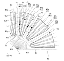
- the upper rotor facing surface 41d is provided with a plurality of upper extending portions 47 extending in the radial direction.
- the upper extending portion 47 is a convex portion that protrudes upward from the upper rotor facing surface 41d.
- the number of upper extending portions 47 provided for each upper rotor facing surface 41d is a number obtained by subtracting 1 from the value obtained by dividing the least common multiple of the number of cores 41 and the number of magnetic poles of upper magnet 33 by the number of cores 41. .
- the number of cores 41 is 12, and the number of magnetic poles of the upper magnet 33 is 10. Therefore, the number of upper extending portions 47 provided for each upper rotor facing surface 41d is four. Accordingly, the upper extending portion 47 includes, for example, four upper extending portions including a first upper extending portion 47a, a second upper extending portion 47b, a third upper extending portion 47c, and a fourth upper extending portion 47d. .
- the cogging torque of the motor 10 can be reduced by setting the number of the upper extending portions 47 provided for each upper rotor facing surface 41d as described above. Details will be described below.
- the upper side magnets 33N and 33S excite the cores 41 on both sides in the circumferential direction of the slot opening Gc with different polarities. Therefore, a magnetic circuit is generated between the upper magnets 33N and 33S and the cores 41 on both sides in the circumferential direction of the slot open Gc. This magnetic circuit generates an attractive force that maintains the state in which the slot open Gc and the magnet gap Gm coincide with each other in the circumferential direction.
- the upper rotor 31 receives a force in the reverse rotational direction (- [theta] Z direction).
- the sum of the attractive forces generated by the magnetic circuit is the cogging torque generated in the upper rotor 31.
- This attractive force becomes the largest when the slot opening Gc and the magnet gap Gm coincide with each other in the circumferential direction. Therefore, a cogging torque peak occurs at the rotation angle of the upper rotor 31 where the slot open Gc and the magnet gap Gm coincide with each other in the circumferential direction.
- One magnet gap Gm passes through the slot open Gc by the number of cores 41 while the upper rotor 31 makes one rotation.
- the total number of times that the slot open Gc and the magnet gap Gm that occur during one rotation of the upper rotor 31 coincide with each other in the circumferential direction is equal to the number of cores 41, the number of magnet gaps Gm, that is, the number of magnetic poles of the upper magnet 33. It is a number multiplied by.
- the locations where the slot opening Gc and the magnet gap Gm coincide with each other in the circumferential direction are simultaneously generated by the greatest common divisor of the number of cores 41 and the number of magnetic poles of the upper magnet 33.
- the peak number of cogging torque generated during one rotation of the upper rotor 31 is obtained by multiplying the number of cores 41 by the number of magnetic poles of the upper magnet 33 and the number of cores 41 and the number of magnetic poles of the upper magnet 33.
- the number divided by the greatest common divisor is the number of cores 41 and the upper magnet 33. The least common multiple with the number of magnetic poles.
- the peak number of cogging torque is the least common multiple of the number of cores 41 and the number of magnetic poles of the upper magnet 33. Therefore, in order to suitably reduce and cancel the cogging torque, the upper extending portion 47 is required by the least common multiple of the number of cores 41 and the number of magnetic poles of the upper magnet 33. Further, the magnet gap Gm and the slot open Gc are arranged at equal intervals in the circumferential direction.
- the slot openings Gc are preferably arranged at equal intervals in the circumferential direction with the center in the circumferential direction as a base point.
- the upper extension 47 cannot be arranged at the position of the slot open Gc. Therefore, in practice, the sum of the upper extending portions 47 arranged on the plurality of upper rotor facing surfaces 41d is reduced by the number of the slot open Gc from the least common multiple of the number of cores 41 and the number of magnetic poles of the upper magnet 33. A number is preferred.
- the number of upper extending portions 47 provided for each upper rotor facing surface 41 d is obtained by dividing the least common multiple of the number of cores 41 and the number of magnetic poles of the upper magnet 33 by the number of cores 41. This is the number obtained by subtracting one. That is, the total number of the upper extending portions 47 provided on all the upper rotor facing surfaces 41 d is a number obtained by subtracting the number of cores 41 from the least common multiple of the number of cores 41 and the number of magnetic poles of the upper magnet 33.
- the number of cores 41 is the same as the number of slot opens Gc.
- the total sum of the upper extending portions 47 arranged on the plurality of upper rotor facing surfaces 41d can be made by subtracting the number of slot openings Gc from the least common multiple of the number of cores 41 and the number of magnetic poles of the upper magnet 33.
- the motor 10 having a structure capable of reducing the cogging torque can be obtained.
- the upper extending portions 47 are arranged at equal intervals in the circumferential direction, and the number of the upper extending portions 47 is the least common multiple of the number of cores 41 and the number of magnetic poles of the upper magnet 33, In addition, when it is assumed that the upper extending portion 47 is also arranged at the position of the slot opening Gc, the upper extending portion 47 is placed at the position of the upper extending portion 47 when the upper extending portions 47 are arranged at equal intervals in the circumferential direction. Including placing.
- the circumferential interval between the upper extending portions 47 adjacent in the circumferential direction across the slot open Gc is the circumferential distance on one upper rotor facing surface 41d. It is larger than the interval in the circumferential direction between the upper extending portions 47 adjacent to each other in the direction.
- the fact that certain objects coincide with each other in the circumferential direction includes that the centers of certain objects in the circumferential direction overlap in the axial direction.
- the core 41 is skewed.
- the timing at which the slot open Gc and the magnet gap Gm coincide can be varied depending on the radial position. Accordingly, the timing at which cogging torque is generated between the upper rotor 31 and the core 41 and the timing at which cogging torque is generated between the lower rotor 32 and the core 41 can be made different depending on the radial position. As a result, the peak of cogging torque can be dispersed, and the magnitude of the peak of cogging torque generated in the motor 10 can be further reduced.
- the upper magnet 33 and the lower magnet 35 are each skewed in the circumferential direction with respect to the radial line. Therefore, the timing at which the slot opening Gc and the magnet gap Gm coincide can be made different depending on the radial position. Thereby, the magnitude of the peak of the cogging torque generated in the motor 10 can be further reduced.
- the arrangement relationship between the upper magnet 33 and the lower magnet 35 is skewed. Therefore, the timing at which the slot open Gc and the magnet gap Gm coincide can be made different between the upper rotor 31 and the lower rotor 32. Thereby, the timing at which cogging torque is generated between the upper rotor 31 and the core 41 and the timing at which cogging torque is generated between the lower rotor 32 and the core 41 can be differentiated. Therefore, the magnitude of the peak of cogging torque generated in the motor 10 can be further reduced.
- the first upper extending portion 47a, the second upper extending portion 47b, the third upper extending portion 47c, and the fourth upper extending portion 47d are arranged in this order along the circumferential direction.
- the first upper extending portion 47a, the second upper extending portion 47b, the third upper extending portion 47c, and the fourth upper extending portion 47d are arranged at equal intervals in the circumferential direction on the upper rotor facing surface 41d. That is, the centers in the circumferential direction of the plurality of upper extending portions 47 provided for each upper rotor facing surface 41d are arranged at equal intervals along the circumferential direction.
- the equally-divided direction line C1 is a radial line that equally divides the stator 40 into the number of least common multiples of the number of cores 41 and the number of magnetic poles of the upper magnet 33 in the circumferential direction when viewed in the axial direction.
- the upper extending portion 47 extends over the entire radial direction of the upper rotor facing surface 41d. Therefore, the cogging torque can be reduced by the upper extending portion 47 at any radial position on the upper rotor facing surface 41d.
- the upper extending portion extends over the entire radial direction of the rotor facing surface.
- both ends in the radial direction of the upper extending portion are the outer line of the rotor facing surface. Including connecting. That is, in the present specification, the upper extending portion extends over the entire radial direction of the rotor facing surface.
- the upper extending portion extends in the radial direction from the radially inner end of the rotor facing surface. Extending to the outer end, and extending the upper extending portion from the circumferential end of the rotor facing surface to the radially outer end.
- the first upper extending portion 47 a is from the core flange portion side surface 41 g to the core flange portion outer side surface 41 h that is the surface of the radially outer end of the upper core flange portion 41 c. Extend.
- the fourth upper extending portion 47d extends from the core flange portion side surface 41f to the core flange portion outer surface 41h.
- the core flange portion outer side surface 41 h is a surface at the radially outer end of the core 41.
- At least one of the upper extending portions 47 provided for each upper rotor facing surface 41 d extends from the side surface on one side in the circumferential direction of the core 41 to the radially outer end of the core 41. .
- the core flange portion side surfaces 41f and 41g are located at the end portion in the circumferential direction of the upper rotor facing surface 41d when viewed in the axial direction.
- the upper extending portion 47 When the upper extending portion 47 is provided along the equally-divided direction line C1 as in the present embodiment, if the slot opening width L4 is constant over the entire radial direction, the upper extending portion 47 includes the first extending portion 47.
- the upper extending portion 47 having a configuration such as the first upper extending portion 47a and the fourth upper extending portion 47d is likely to be included.
- the upper extension 47 includes an upper extension extending from the side surface on one side in the circumferential direction of the core 41 to the radially outer end of the core 41 so that the slot open width L4 is the same at any radial position. Cheap.
- the second upper extending portion 47b and the third upper extending portion 47c extend from the core flange portion inner side surface 41i, which is the radially inner end of the upper core flange portion 41c, to the core flange portion outer surface 41h.
- the core flange portion inner side surface 41 i is a surface at the radially inner end of the core 41.
- the stretched part width L2 which is the dimension in the circumferential direction of the upper stretched part 47, increases, for example, from the radially inner side toward the radially outer side.
- the distance in the circumferential direction in which the upper magnet 33 moves when the upper rotor 31 makes one rotation is such that the upper magnet 33 moves from the radially inner end of the upper magnet 33.
- the diameter increases toward the outer end in the radial direction. Therefore, for example, when the extended portion width L2 is the same in the entire radial direction, the ratio of the extended portion width L2 to the circumferential distance traveled by the upper magnet 33 during one rotation is the radial direction of the upper magnet 33. It decreases from the inner end toward the radially outer end of the upper magnet 33. Thereby, there exists a possibility that the reduction effect of a cogging torque may become small as the part near the radial direction outer end of the upper magnet 33.
- the extending portion width L2 increases from the radially inner side toward the radially outer side, the extending portion width L2 with respect to the circumferential distance traveled by the upper magnet 33 during one rotation. It is easy to make the ratio of the same over the entire radial direction. Thereby, according to this embodiment, it is easy to reduce cogging torque irrespective of a radial direction position.
- extended portion outlines VL1 and VL2 which are outlines on both sides in the circumferential direction of the upper extended portion 47 extend on a straight line passing through the central axis J. Therefore, the ratio of the extending portion width L2 to the circumferential distance in which the upper magnet 33 moves during one rotation can be made the same at any radial position. This makes it easier to reduce the cogging torque regardless of the radial position.
- the upper extending portion 47 that is a convex portion can be provided with the upper rotor facing surface 41d as a reference, and thus the upper extending portion 47 can reduce the cogging torque.
- the shape of the cross section orthogonal to the radial direction of the upper extending portion 47 is not particularly limited, and may be, for example, a semicircular shape or a polygonal shape.
- the shape of the cross section orthogonal to the radial direction of the upper extending portion 47 is, for example, a trapezoid.
- the lower core flange portion 41b is connected to the lower end of the core columnar portion 41a.
- the lower core flange portion 41b has a plate shape extending in the radial direction.
- the lower core flange portion 41b extends on both sides in the radial direction with respect to the core columnar portion 41a.
- the planar view (XY plane view) shape of the lower core flange portion 41b is the same as the planar view shape of the upper core flange portion 41c. That is, the shape of the lower rotor facing surface 41e, which is the lower surface of the lower core flange portion 41b, is the same as that of the upper rotor facing surface 41d.
- the lower rotor facing surface 41e is a surface facing the lower rotor 32 of the core 41.
- the lower rotor facing surface 41e is provided for each core 41. That is, the plurality of cores 41 each have a lower rotor facing surface 41 e that is a surface facing the lower rotor 32.
- the lower rotor facing surface 41e is provided with a plurality of lower extending portions 48 extending in the radial direction.
- the lower extending portion 48 is a convex portion that protrudes downward from the lower rotor facing surface 41e.
- the peak number of cogging torque generated in the upper rotor 31 is determined by the number of cores 41 and the number of magnetic poles of the upper magnet 33.
- the lower rotor 32 determines the number of cogging torque peaks generated in the lower rotor 32 by the number of cores 41 and the number of magnetic poles of the lower magnet 35. Therefore, in order to suitably reduce and cancel the cogging torque of the lower rotor 32, as in the case of the cogging torque in the upper rotor 31, the least common multiple of the number of cores 41 and the number of magnetic poles of the lower magnet 35 is set.
- the lower extending portion 48 is required by the amount.
- the magnet gaps Gm are arranged at equal intervals in the circumferential direction. Therefore, in the lower magnet 35, when any slot open Gc and any magnet gap Gm coincide with each other in the circumferential direction, the other magnet gap Gm coincides with the lower extending portion 48 in the circumferential direction.
- the lower extending portions 48 are preferably arranged at equal intervals in the circumferential direction with the center in the circumferential direction of one of the slot openings Gc as a base point.
- the number of magnetic poles of the lower magnet 35 is the same as the number of magnetic poles of the upper magnet 33. Accordingly, the total number of upper extending portions 47 and the total number of lower extending portions 48 are the same, and the circumferential arrangement of the upper extending portions 47 and the circumferential arrangement of the lower extending portions 48 are the same. Is preferred. That is, it is preferable that the arrangement of the extending portions is the same when the core 41 is viewed from above and when the core 41 is viewed from below. By arranging the extending portion in this way, both the cogging torque generated in the upper rotor 31 and the cogging torque generated in the lower rotor 32 can be suitably reduced.
- the preferable arrangement relationship between the upper extending portion 47 and the lower extending portion 48 described above is that the upper magnet 33 and the lower magnet 35 are skewed in the circumferential direction with respect to the central axis J as in the present embodiment. This is the same even when the skew is not applied. That is, even when the upper magnet 33 and the lower magnet 35 are skewed in the circumferential direction with respect to the central axis J as in the present embodiment, the total number of the upper extending portions 47 and the lower extending portions are reduced.
- the cogging torque generated in the upper rotor 31 and the lower rotor 32 are made the same with the total number of 48 and the circumferential arrangement of the upper extending portion 47 and the circumferential arrangement of the lower extending portion 48 are the same. Both the cogging torques generated in the above can be suitably reduced.
- the number of lower extending portions 48 provided for each lower rotor facing surface 41 e is obtained by dividing the least common multiple of the number of cores 41 and the number of magnetic poles of the lower magnet 35 by the number of cores 41. This is the number obtained by subtracting one.
- the number of cores 41 is 12, and the number of magnetic poles of the lower magnet 35 is 10. Therefore, the number of lower extending portions 48 provided for each lower rotor facing surface 41e is four. Accordingly, the lower extending portion 48 includes, for example, four of the first lower extending portion 48a, the second lower extending portion 48b, the third lower extending portion 48c, and the fourth lower extending portion 48d. Includes lower stretch.
- both the cogging torque generated in the upper rotor 31 and the cogging torque generated in the lower rotor 32 can be reduced. Thereby, the cogging torque of the entire motor 10 can be further reduced.
- the upper extending portion 47 and the lower extending portion 48 are provided at the same position in the circumferential direction. In other words, the upper extending portion 47 and the lower extending portion 48 overlap each other in the axial direction. Therefore, the upper extending portion 47 and the lower extending portion 48 reduce the cogging torque generated between the upper rotor 31 and the core 41 and the cogging torque generated between the lower rotor 32 and the core 41 at the same timing. it can. Thereby, the cogging torque of the entire motor 10 can be further reduced.
- the first upper extending portion 47a and the first lower extending portion 48a are provided at the same position in the circumferential direction.
- the second upper extending portion 47b and the second lower extending portion 48b are provided at the same position in the circumferential direction.
- the third upper extending portion 47c and the third lower extending portion 48c are provided at the same position in the circumferential direction.
- the fourth upper extending portion 47d and the fourth lower extending portion 48d are provided at the same position in the circumferential direction.
- two rotors are provided, and the upper rotor 31 and the core 41 and the lower rotor 32 and the core 41 face each other in the axial direction (Z-axis direction).
- the facing area of the rotor facing the can be increased.
- the rotational torque of the motor 10 can be increased.
- cogging torque is generated in each of the rotors, so that the total sum of the cogging torques generated in the entire motor 10 increases.
- both the cogging torque in the upper rotor 31 and the cogging torque in the lower rotor 32 are suitably reduced by the upper extending portion 47 and the lower extending portion 48. it can. Therefore, according to this embodiment, since the opposing area of the rotor facing the stator 40 in the entire motor 10 can be increased while suitably reducing the respective cogging torques, the rotational torque of the motor 10 can be further increased.
- Only one of the upper extending portion 47 and the lower extending portion 48 may be provided.
- the stretched portion width L2 may be the same at any position in the radial direction.
- the extended portion outlines VL1 and VL2 intersect with a straight line passing through the central axis J.
- the upper extending portion 47 may be provided in a part of the upper rotor facing surface 41d in the radial direction.
- the slot open width L4 may vary depending on the radial position.
- the slot open width L4 may increase from the radially inner side toward the radially outer side.
- a configuration in which the core flange portion side surfaces 41f and 41g extend along the radial line can be employed.
- the upper extending portion 47 may include only one upper extending portion extending from the side surface on one side in the circumferential direction of the core 41 to the radially outer end of the core 41, or may include three or more upper extending portions. Further, the upper extending portion 47 may not include the upper extending portion extending from the side surface on one side in the circumferential direction of the core 41 to the radially outer end of the core 41.
- each part of the core 41 may be a separate member. That is, the upper extending portion 47 may be a separate member from the upper core flange portion 41c.
- the number of upper magnets 33 and the number of cores 41 are not particularly limited.
- the number of cores 41 can be, for example, 2n: 3n, 4n: 3n, 8n: 9n, 10n: 12n.
- n is a natural number.
- the number of upper magnets 33: the number of cores 41 is 10:12.
- the magnet gap Gm may not be provided. That is, the upper magnet 33N and the upper magnet 33S may be arranged in contact with each other. The same applies to the lower magnet 35.
- the contact boundary between the upper magnet 33N and the upper magnet 33S corresponds to the magnet gap Gm in the description of the cogging torque. That is, when the boundary between the upper magnet 33N and the upper magnet 33S and the slot opening Gc coincide with each other in the circumferential direction, a peak of cogging torque occurs.
- each of the upper magnet 33 and the lower magnet 35 may be a single member.
- the upper magnet 33 and the lower magnet 35 can be formed into, for example, an annular shape in which N poles and S poles are alternately arranged along the circumferential direction.
- the boundary between the N pole and the S pole corresponds to the magnet gap Gm in the description of the cogging torque.
- the second embodiment is different from the first embodiment in that the upper extending portion is a recess.
- description may be abbreviate
- FIG. 6 is a perspective view showing the core 141 of the present embodiment.
- the core 141 includes a core columnar portion 41a, an upper core flange portion 141c, and a lower core flange portion 141b.
- the upper rotor facing surface 141d which is the upper surface of the upper core flange portion 141c, is provided with a plurality of upper extending portions 147 extending in the radial direction.
- the upper rotor facing surface 141 d is a surface facing the upper rotor 31.
- the upper extending portion 147 is a recess that is recessed downward from the upper rotor facing surface 141d.
- the shape of the cross section orthogonal to the radial direction of the upper extending portion 147 is not particularly limited. In the example of FIG. 6, the shape of the cross section orthogonal to the radial direction of the upper extending portion 147 is, for example, a semicircular arc shape.
- the upper extending portion 147 includes a first upper extending portion 147a, a second upper extending portion 147b, a third upper extending portion 147c, and a fourth upper extending portion 147d.
- the first upper extending portion 147a, the second upper extending portion 147b, the third upper extending portion 147c, and the fourth upper extending portion 147d are arranged along the circumferential direction in this order.
- the first upper extending portion 147a is the same as the first upper extending portion 47a of the first embodiment except that it is a concave portion.
- the second upper extending portion 147b is the same as the second upper extending portion 47b of the first embodiment except that it is a recess.
- the third upper extending portion 147c is the same as the third upper extending portion 47c of the first embodiment except that it is a recess.
- the fourth upper extending portion 147d is the same as the fourth upper extending portion 47d of the first embodiment except that it is a recess.
- the lower rotor facing surface 141e which is the lower surface of the lower core flange portion 141b, is provided with a plurality of lower extending portions extending in the radial direction.
- the lower rotor facing surface 141 e is a surface facing the lower rotor 32.
- the lower extending portion provided in the lower core flange portion 141b is a recess that is recessed upward from the lower rotor facing surface 141e.
- Other configurations of the lower extending portion are the same as those of the upper extending portion 147.
- the other configuration of the core 141 is the same as the configuration of the core 41 of the first embodiment.
- the cogging torque can be reduced by the upper extending portion 147 that is a recess and the lower extending portion (not shown).
- the upper extending portion 147 is a convex portion that protrudes upward from the upper rotor facing surface 141d or a concave portion that is recessed downward from the upper rotor facing surface 141d.
- a configuration in which the lower extending portion is a convex portion that protrudes downward from the lower rotor facing surface 141e or a concave portion that is concave upward from the lower rotor facing surface 141e can be employed.
- a part of the upper extending portion 147 may be a convex portion that protrudes upward from the upper rotor facing surface 141d. Further, a part of the lower extending portion may be a convex portion that protrudes downward from the lower rotor facing surface 141e.
- all of the upper extending portion 147 may be one of the convex portion and the concave portion, and all of the lower extending portion may be the other one of the convex portion and the concave portion.
Landscapes
- Engineering & Computer Science (AREA)
- Power Engineering (AREA)
- Iron Core Of Rotating Electric Machines (AREA)
- Permanent Field Magnets Of Synchronous Machinery (AREA)
- Permanent Magnet Type Synchronous Machine (AREA)
Abstract
本発明のモータの一つの態様は、シャフトと、上側ロータと、上側ロータと軸方向に対向するステータと、ベアリングと、を備える。上側ロータは、ステータと軸方向に対向する上側マグネットを有し、かつ、ステータの上側に位置する。上側マグネットは、周方向に沿って配置された複数の磁極を有する。ステータは、周方向に沿って配置された複数のコアを有する。複数のコアは、上側ロータと対向する面である上側ロータ対向面をそれぞれ有する。上側ロータ対向面には、径方向に延びる複数の上側延伸部が設けられる。上側延伸部は、上側ロータ対向面から上側に凸となる凸部、または上側ロータ対向面から下側に凹となる凹部である。上側ロータ対向面ごとに設けられる上側延伸部の数は、コアの数と上側マグネットの磁極の数との最小公倍数をコアの数で除した値から1を減じた数である。
Description
本発明は、モータに関する。
例えば、日本特開2008-125278号公報には、アキシャルエアギャップ型電動機が記載される。
上記のようなアキシャルギャップ型電動機においては、コアとマグネットとの間に磁力による引力が生じ、ロータの回転に対する抵抗が生じる。このような抵抗をコギングトルクと呼ぶ。コギングトルクが大きいと、電動機の回転トルクのムラが大きくなり、モータに振動および騒音が生じる問題がある。
また、コギングトルクは、電動機に電流が供給されない状態でも発生する。そのため、電動パワーステアリング装置および電動アシスト付き自転車等のような、電動機に電流が供給されない状態においてもシャフトを回転させる用途に電動機が用いられる場合、コギングトルクが大きいと、使用者の操作負担が増加する問題がある。
本発明の一つの態様は、上記問題に鑑みて、コギングトルクを低減できる構造を有するモータを提供することを目的の一つとする。
本開示のモータの一つの態様は、上下方向に延びる中心軸を中心とするシャフトと、上側ロータと、ステータと、ベアリングと、を含む。上側ロータは、シャフトに取り付けられる。ステータは、上側ロータと軸方向に対向する。ベアリングは、シャフトを支持する。
上側ロータは、ステータと軸方向に対向する上側マグネットを有し、かつ、ステータの上側に位置する。上側マグネットは、周方向に沿って配置された複数の磁極を有する。ステータは、周方向に沿って配置された複数のコアと、コアに巻き回されたコイルと、を有する。複数のコアは、上側ロータと対向する面である上側ロータ対向面をそれぞれ有する。上側ロータ対向面には、径方向に延びる複数の上側延伸部が設けられる。上側延伸部は、上側ロータ対向面から上側に凸となる凸部、または上側ロータ対向面から下側に凹となる凹部である。上側ロータ対向面ごとに設けられる上側延伸部の数は、コアの数と上側マグネットの磁極の数との最小公倍数をコアの数で除した値から1を減じた数である。
上側ロータは、ステータと軸方向に対向する上側マグネットを有し、かつ、ステータの上側に位置する。上側マグネットは、周方向に沿って配置された複数の磁極を有する。ステータは、周方向に沿って配置された複数のコアと、コアに巻き回されたコイルと、を有する。複数のコアは、上側ロータと対向する面である上側ロータ対向面をそれぞれ有する。上側ロータ対向面には、径方向に延びる複数の上側延伸部が設けられる。上側延伸部は、上側ロータ対向面から上側に凸となる凸部、または上側ロータ対向面から下側に凹となる凹部である。上側ロータ対向面ごとに設けられる上側延伸部の数は、コアの数と上側マグネットの磁極の数との最小公倍数をコアの数で除した値から1を減じた数である。
本開示の一つの態様によれば、コギングトルクを低減できる構造を有するモータが提供される。
以下、図面を参照しながら、本開示の好適な実施形態に係るモータについて説明する。なお、本開示の範囲は、以下の実施の形態に限定されず、本開示の技術的思想の範囲内で任意に変更可能である。また、以下の図面においては、各構成をわかりやすくするために、各構造における縮尺および数等を、実際の構造における縮尺および数等と異ならせる場合がある。
また、図面においては、適宜3次元直交座標系としてXYZ座標系を示す。XYZ座標系において、Z軸方向は、図1に示す中心軸Jの軸方向と平行な方向または略平行な方向とする。X軸方向は、Z軸方向と直交する方向または略直行する方向であって図1の左右方向とする。Y軸方向は、X軸方向とZ軸方向との両方と直交する方向または略直行する方向とする。
また、以下の説明においては、中心軸Jの延びる方向(Z軸方向)を上下方向とする。Z軸方向の正の側(+Z側)を「上側」と呼び、Z軸方向の負の側(-Z側)を「下側」と呼ぶ。なお、上下方向、上側および下側とは、単に説明のために用いられる名称であって、実際の位置関係や方向を限定しない。また、特に断りのない限り、中心軸Jに平行な方向または略平行な方向(Z軸方向)を単に「軸方向」と呼び、中心軸Jを中心とする径方向を単に「径方向」と呼び、中心軸Jを中心とする周方向(θZ方向)、すなわち、中心軸Jの軸周りを単に「周方向」と呼ぶ。
なお、本明細書において、軸方向に延びる、とは、厳密に軸方向に延びる場合に加えて、軸方向に対して、45度未満の範囲で傾いた方向に延びる場合も含む。また、本明細書において、径方向に延びる、とは、厳密に径方向、すなわち、軸方向に対して垂直な方向に延びる場合に加えて、径方向に対して、45度未満の範囲で傾いた方向に延びる場合も含む。
図1は、好適な第1実施形態のモータ10を示す断面図である。モータ10は、アキシャルギャップモータである。図1に示すように、モータ10は、ハウジング11と、シャフト20と、2つのロータである上側ロータ31および下側ロータ32と、上側ベアリング51と、下側ベアリング52と、ステータ40と、バスバーユニット70と、コネクタ71と、を備える。
ハウジング11は、モータ10のモータケースである。ハウジング11は、例えば、金属製または樹脂製である。ハウジング11は、シャフト20と、上側ロータ31と、下側ロータ32と、ステータ40と、上側ベアリング51と、下側ベアリング52と、バスバーユニット70と、を収容する。ハウジング11は、中間ハウジング12と、下側ハウジング13と、上側ハウジング14と、を有する。下側ハウジング13は、底壁部13bと、筒部13aと、下側ベアリング保持部15と、を有する。
上側ハウジング14は、中間ハウジング12の上側に、後述するカバー45のカバーフランジ部45bを介して取り付けられる。上側ハウジング14は、例えば、有蓋の円筒状である。上側ハウジング14の径方向内側には、上側ロータ31、ステータ40、およびバスバーユニット70が位置する。
なお、本明細書において、モータケース、とは、例えば、モータにおけるロータ、ステータ、およびシャフト等の駆動部品を収容して保護する部品のうちモータ外部の空間と接する部品である。
シャフト20は、上下方向に延びる中心軸Jを中心とする。シャフト20は、上側ベアリング51と下側ベアリング52とによって、中心軸J周りに回転可能に支持される。すなわち、上側ベアリング51および下側ベアリング52は、シャフト20を支持するベアリングである。シャフト20の下端は、出力軸孔15aを介してハウジング11の外部に突出する。
上側ロータ31と下側ロータ32とは、軸方向に所定の間隔を空けてシャフト20に取り付けられる。上側ロータ31は、ステータ40の上側に位置する。上側ロータ31は、上側ロータ本体34と、複数の上側マグネット33と、を有する。
上側ロータ本体34は、例えば、径方向に延びる円板状である。上側ロータ本体34は、シャフト20の上端に固定される。上側マグネット33は、上側ロータ本体34の下面に固定されるマグネットである。図示は省略するが、複数の上側マグネット33は、周方向に沿って配置される。上側マグネット33の磁極は、N極とS極とが周方向に沿って交互に設けられる。上側マグネット33は、ステータ40と軸方向に対向する。
下側ロータ32は、ステータ40の下側に位置する。下側ロータ32は、下側ロータ本体36と、複数の下側マグネット35と、を有する。下側ロータ本体36は、例えば、径方向に延びる円板状である。下側ロータ本体36は、シャフト20に固定される。下側マグネット35は、下側ロータ本体36の上面に固定されるマグネットである。複数の下側マグネット35は、周方向に沿って配置される。下側マグネット35の磁極は、N極とS極とが周方向に沿って交互に設けられる。下側マグネット35は、ステータ40と軸方向に対向する。上側マグネット33と下側マグネット35とは、互いに異極が軸方向に対向する。これにより、上側ロータ31と下側ロータ32とによって回転トルクが得られるため、モータ10の回転トルクを大きくできる。
ステータ40は、2つのロータの間、すなわち、上側ロータ31と下側ロータ32との間に配置される。ステータ40は、複数のコア41と、コイル42と、インシュレータ43と、上側ベアリングホルダ44と、カバー45と、モールド樹脂部46と、を有する。ステータ40は、例えば、モールド成型品である。
複数のコア41は、周方向に沿って配置される。複数のコア41は、上側ベアリングホルダ44とカバー45との径方向の間に位置する。複数のコア41は、例えば、12個設けられる。
インシュレータ43は、コア41に装着される。インシュレータ43は、例えば、ボビン状である。インシュレータ43は、例えば、樹脂材料で成型された部材である。コイル42は、インシュレータ43を介して、コア41に巻き回される。コイル42は、コイル引出線42aを有する。コイル42は、コア41を励磁する。
コイル引出線42aは、コイル42から上側に引き出される。コイル引出線42aは、コア41よりも上側に延びる。コイル引出線42aは、バスバーユニット70のバスバーと電気的に接続される。コイル引出線42aは、コイル42を構成する巻線の一部であってもよいし、コイル42を構成する巻線とは別部材であってもよい。
筒状の上側ベアリングホルダ44は、上側ベアリング51を保持するベアリングホルダである。上側ベアリングホルダ44は、複数のコア41の径方向内側かつ、シャフト20の径方向外側に位置する。上側ベアリングホルダ44は、例えば、中心軸Jと同心の円筒状である。上側ベアリングホルダ44の内周面であるホルダ内周面44eには、上側ベアリング51が保持される。
筒状のカバー45は、複数のコア41の径方向外側に配置される。カバー45は、カバー筒状部45aと、カバーフランジ部45bと、を有する。カバー筒状部45aは、軸方向に延び軸方向両端に開口する筒状である。カバー筒状部45aは、例えば、中心軸Jと同心の円筒状である。
カバーフランジ部45bは、カバー筒状部45aの下端から径方向外側に延びる。カバーフランジ部45bの下面は、中間ハウジング12の上面と接触する。カバーフランジ部45bの上面は、上側ハウジング14の下面と接触する。カバーフランジ部45bは、例えば、ビスによってハウジング11と固定される。これにより、ステータ40がハウジング11に固定される。カバーフランジ部45bの径方向外側の端面は、モータ10の外部に露出する。
モールド樹脂部46は、ステータ40を構成する各部品の間に位置する。モールド樹脂部46は、例えば、コイル42およびインシュレータ43と、上側ベアリングホルダ44およびカバー45との径方向の間等に位置する。
バスバーユニット70は、上側ロータ31の上側に位置する。バスバーユニット70には、コイル引出線42aが接続される。バスバーユニット70は、図示しないバスバーを保持する。バスバーはコイル引出線42aと電気的に接続される。バスバーの一端は、コネクタ71を介してハウジング11の外部に露出する。
コネクタ71は、例えば、上側ハウジング14に設けられる。図示は省略するが、コネクタ71は、上側に開口する穴部を有する。穴部の内側には、バスバーユニット70におけるバスバーの一端が露出する。コネクタ71には、図示しない外部電源が接続される。これにより、外部電源から、バスバーおよびコイル引出線42aを介してステータ40に電源が供給される。
次に、上側ロータ31および下側ロータ32について詳細に説明する。図2は、本実施形態の上側ロータ31を示す平面図である。図2に示すように、上側マグネット33は、複数の上側マグネット33Nと、複数の上側マグネット33Sと、を含む。
上側マグネット33Nは、N極に着磁されたマグネットである。上側マグネット33Sは、S極に着磁されたマグネットである。すなわち、各上側マグネット33Nおよび各上側マグネット33Sは、それぞれ1つの磁極を有する。複数の上側マグネット33Nと複数の上側マグネット33Sとは、マグネット間隙Gmを介して周方向に沿って交互に配置される。これにより、上側マグネット33の磁極は、N極とS極とが周方向に沿って交互に設けられる。マグネット間隙Gmは、周方向に隣り合う上側マグネット33Nと上側マグネット33Sとの隙間であり、周方向に隣り合うN極とS極との境界である。
上側マグネット33Nおよび上側マグネット33Sは、例えば、それぞれ5個ずつ設けられる。すなわち、上側マグネット33の磁極の数は、例えば、10である。
図1に示すように、下側マグネット35は、複数の下側マグネット35Nと、複数の下側マグネット35Sと、を含む。下側マグネット35Nは、N極に着磁されたマグネットである。下側マグネット35Sは、S極に着磁されたマグネットである。図示は省略するが、複数の下側マグネット35Nと複数の下側マグネット35Sとは、周方向に沿って交互に配置される。これにより、下側マグネット35の磁極は、N極とS極とが周方向に沿って交互に設けられる。下側マグネット35の磁極の数は、上側マグネット33と同様に、例えば、10である。すなわち、上側マグネット33の磁極の数と下側マグネット35の磁極の数とは、同じである。これにより、モータ10のマグネットが有する磁極の数の総和は、上側マグネット33の磁極の数の2倍となる。
下側マグネット35Nは、上側マグネット33Sと軸方向に対向する。下側マグネット35Sは、上側マグネット33Nと軸方向に対向する。これにより、上側マグネット33と下側マグネット35とは、互いに異極が軸方向に対向する。
図3は、ステータ40を径方向に視た断面図である。図3に示すように、上側マグネット33N,33Sの周方向の位置と下側マグネット35N,35Sの周方向の位置とは、わずかにずれる。これにより、上側マグネット33N,33Sと下側マグネット35N,35Sとの間に生じる磁界が中心軸Jに対して周方向に傾く。すなわち、上側マグネット33と下側マグネット35との配置関係には、中心軸Jに対して周方向に傾くスキューが施される。上側マグネット33N,33Sと下側マグネット35N,35Sとの周方向のずれ角度は、例えば、3度以上、6度以下である。
図2に示すように、上側マグネット33N,33Sの周方向両側の外形線は、平面視において、中心軸Jを通る径方向線と交差する。図示は省略するが、上側マグネット33N,33Sと同様に、下側マグネット35N,35Sの周方向両側の外形線は、平面視において、中心軸Jを通る径方向線と交差する。これにより、上側マグネット33N,33Sおよび下側マグネット35N,35Sのそれぞれには、径方向線に対して周方向に傾くスキューが施される。
次に、コア41について詳細に説明する。図4および図5は、本実施形態のコア41を示す図である。図4は、平面図である。図5は、斜視図である。
なお、以下の説明において、θZ方向は、+Z側から-Z側に向かって視て反時計回りを正の向きとし、+Z側から-Z側に向かって視て時計回りを負の向きとする。また、θZ方向の正の向きに進む方向(+θZ方向)を、正回転方向と呼び、θZ方向の負の向きに進む方向(-θZ方向)を、逆回転方向と呼ぶ。
図4に示すように、複数のコア41は、スロットオープンGcを介して周方向に等間隔に配置される。スロットオープンGcは、周方向に隣り合うコア41同士の隙間である。スロットオープンGcの周方向の寸法であるスロットオープン幅L4は、径方向のいずれの位置においても同じである。すなわち、周方向に隣り合うコア41同士の間の周方向の距離は、径方向のいずれの位置においても同じである。これにより、コア41が上側マグネット33と対向するタイミング、およびコア41が下側マグネット35と対向するタイミングを、径方向位置によって異ならせることができる。すなわち、コア41にスキューを施すことができる。
コア41は、磁性体製である。コア41は、例えば、単一の部材である。図3および図5に示すように、コア41は、コア柱状部41aと、上側コアフランジ部41cと、下側コアフランジ部41bと、上側延伸部47と、下側延伸部48と、を有する。図5に示すように、コア柱状部41aは、軸方向に延びる柱状である。コア柱状部41aには、コイル42が巻き回される。
上側コアフランジ部41cは、コア柱状部41aの上端に接続される。上側コアフランジ部41cは、径方向に延びる板状である。上側コアフランジ部41cは、コア柱状部41aよりも径方向両側に延びる。
図4に示すように、上側コアフランジ部41cの平面視(XY面視)形状は、径方向内側から径方向外側に向かって拡がる扇形である。すなわち、上側コアフランジ部41cの上面である上側ロータ対向面41dの形状は、周方向の寸法である上側ロータ対向面幅L1が径方向内側から径方向外側に向かうに従って大きくなる扇形である。
上側ロータ対向面41dは、コア41の上側ロータ31と対向する面である。上側ロータ対向面41dは、コア41ごとにそれぞれ設けられる。すなわち、複数のコア41は、上側ロータ31と対向する面である上側ロータ対向面41dをそれぞれ有する。
上側コアフランジ部41cの周方向の側面であるコアフランジ部側面41f,41gは、中心軸Jを通る径方向線と交差する。コアフランジ部側面41f,41gは、コア41の周方向の側面である。
上側ロータ対向面41dには、径方向に延びる複数の上側延伸部47が設けられる。上側延伸部47は、上側ロータ対向面41dから上側に凸となる凸部である。上側ロータ対向面41dごとに設けられる上側延伸部47の数は、コア41の数と上側マグネット33の磁極の数との最小公倍数をコア41の数で除した値から1を減じた数である。
例えば、コア41の数は12であり、上側マグネット33の磁極の数は10である。そのため、上側ロータ対向面41dごとに設けられる上側延伸部47の数は、4となる。これにより、上側延伸部47は、例えば、第1上側延伸部47aと、第2上側延伸部47bと、第3上側延伸部47cと、第4上側延伸部47dとの4つの上側延伸部を含む。
上側ロータ対向面41dごとに設けられる上側延伸部47の数を上記のようにすることで、モータ10のコギングトルクを低減できる。以下、詳細に説明する。
スロットオープンGcとマグネット間隙Gmとが周方向に一致すると、上側マグネット33N,33Sによって、スロットオープンGcの周方向両側のコア41が互いに異極に励磁される。そのため、上側マグネット33N,33Sと、スロットオープンGcの周方向両側のコア41との間に、磁気回路が生じる。この磁気回路によって、スロットオープンGcとマグネット間隙Gmとが周方向に一致する状態を保持する引力が生じる。
例えば、上側ロータ31が正回転方向(+θZ方向)に動く場合、この引力によって、上側ロータ31は、逆回転方向(-θZ方向)に力を受ける。この磁気回路による引力の総和が上側ロータ31に生じるコギングトルクとなる。この引力は、スロットオープンGcとマグネット間隙Gmとが周方向に一致した際に、最も大きくなる。そのため、スロットオープンGcとマグネット間隙Gmとが周方向に一致する上側ロータ31の回転角度において、コギングトルクのピークが生じる。
1つのマグネット間隙Gmは、上側ロータ31が1回転する間に、コア41の数だけスロットオープンGcを通過する。すなわち、上側ロータ31が1回転する間に生じるスロットオープンGcとマグネット間隙Gmとが周方向に一致する延べ回数は、コア41の数に、マグネット間隙Gmの数、すなわち上側マグネット33の磁極の数を乗じた数となる。一方、スロットオープンGcとマグネット間隙Gmとが周方向に一致する箇所は、コア41の数と上側マグネット33の磁極の数との最大公約数だけ同時に生じる。
したがって、上側ロータ31が1回転する間に生じるコギングトルクのピーク数は、コア41の数に上側マグネット33の磁極の数を乗じた数を、コア41の数と上側マグネット33の磁極の数との最大公約数で除した数となる。コア41の数に上側マグネット33の磁極の数を乗じた数をコア41の数と上側マグネット33の磁極の数との最大公約数で除した数とは、コア41の数と上側マグネット33の磁極の数との最小公倍数である。
図3に示すように、マグネット間隙Gmと、上側延伸部47、例えば図3では第2上側延伸部47bとが周方向に一致する場合、第2上側延伸部47bは磁気的に周方向のどちらの方向にもトルクが発生しない状態となる。この状態からマグネット間隙Gmが正回転方向側(+θZ側)にわずかにずれると、第2上側延伸部47bと、第2上側延伸部47bの正回転方向側に位置する上側コアフランジ部41cの部分とが、互いに異極に励磁される。
これにより、上側マグネット33N,33Sと、第2上側延伸部47bと、第2上側延伸部47bの正回転方向側(+θZ側)に位置する上側コアフランジ部41cの部分との間に、磁気回路が生じ、上側マグネット33を正回転方向側に動かす斥力が生じる。すなわち、この斥力によって、上述した引力と逆向きの力を上側ロータ31に加えることができる。したがって、上側延伸部47を設けることで、コギングトルクのピークを低減できる。
上述したようにコギングトルクのピーク数は、コア41の数と上側マグネット33の磁極の数との最小公倍数である。そのため、コギングトルクを好適に低減し、打ち消すためには、コア41の数と上側マグネット33の磁極の数との最小公倍数の分だけ上側延伸部47が必要である。また、マグネット間隙GmおよびスロットオープンGcは、周方向に等間隔に配置される。そのため、いずれかのスロットオープンGcといずれかのマグネット間隙Gmとが周方向に一致する際に、その他のマグネット間隙Gmを上側延伸部47と周方向に一致させるためには、上側延伸部47は、いずれかのスロットオープンGcの周方向の中心を基点として、周方向に等間隔に配置されることが好ましい。
しかし、スロットオープンGcの位置には上側延伸部47を配置できない。そのため、実際には、複数の上側ロータ対向面41dに配置される上側延伸部47の総和を、コア41の数と上側マグネット33の磁極の数との最小公倍数からスロットオープンGcの数を減じた数とすることが好ましい。
本実施形態によれば、上側ロータ対向面41dごとに設けられる上側延伸部47の数は、コア41の数と上側マグネット33の磁極の数との最小公倍数をコア41の数で除した値から1を減じた数である。すなわち、すべての上側ロータ対向面41dに設けられる上側延伸部47の数の総和は、コア41の数と上側マグネット33の磁極の数との最小公倍数からコア41の数を減じた数である。コア41の数は、スロットオープンGcの数と同じである。したがって、複数の上側ロータ対向面41dに配置される上側延伸部47の総和を、コア41の数と上側マグネット33の磁極の数との最小公倍数からスロットオープンGcの数を減じた数とできる。
これにより、上側延伸部47を周方向に等間隔に配置することで、いずれか1つのスロットオープンGcと、いずれか1つのマグネット間隙Gmとが周方向に一致する際に、スロットオープンGcと周方向に一致しない他のすべてのマグネット間隙Gmを、いずれかの上側延伸部47と周方向に一致させることが可能である。したがって、スロットオープンGcとマグネット間隙Gmとが周方向に一致してコギングトルクのピークが生じる際に、複数の上側延伸部47による斥力によってコギングトルクと逆向きの力を上側ロータ31に加えて、コギングトルクのピークの大きさを低減しやすい。
以上により、本実施形態によれば、コギングトルクを低減することができる構造を有するモータ10が得られる。
なお、本明細書において、上側延伸部47を周方向に等間隔に配置する、とは、上側延伸部47の数がコア41の数と上側マグネット33の磁極の数との最小公倍数であり、かつ、スロットオープンGcの位置にも上側延伸部47を配置したと仮定した場合に、上側延伸部47を周方向に等間隔に配置したときの上側延伸部47の位置に、上側延伸部47を配置することを含む。実際にはスロットオープンGcには上側延伸部47を配置できないため、スロットオープンGcを挟んで周方向に隣り合う上側延伸部47同士の周方向の間隔は、1つの上側ロータ対向面41d上において周方向に隣り合う上側延伸部47同士の周方向の間隔よりも大きい。
また、本明細書において、ある対象同士が周方向に一致するとは、ある対象の周方向の中心同士が、軸方向に重なることを含む。
また、本実施形態によれば、上述したようにスロットオープン幅L4が径方向全体において一定であるため、コア41にスキューが施される。これにより、スロットオープンGcとマグネット間隙Gmとが一致するタイミングを、径方向位置によって異ならせることができる。したがって、上側ロータ31とコア41との間にコギングトルクが生じるタイミング、および下側ロータ32とコア41との間にコギングトルクが生じるタイミングを、それぞれ径方向位置によって異ならせることができる。その結果、コギングトルクのピークを分散させることができ、モータ10に生じるコギングトルクのピークの大きさをより低減できる。
また、本実施形態によれば、上述したように上側マグネット33および下側マグネット35にはそれぞれ径方向線に対して周方向に傾くスキューが施される。そのため、スロットオープンGcとマグネット間隙Gmとが一致するタイミングを、径方向位置によってより異ならせることができる。これにより、モータ10に生じるコギングトルクのピークの大きさをより低減できる。
また、本実施形態によれば、上述したように上側マグネット33と下側マグネット35との配置関係にはスキューが施される。そのため、スロットオープンGcとマグネット間隙Gmとが一致するタイミングを、上側ロータ31と下側ロータ32とで異ならせることができる。これにより、上側ロータ31とコア41との間にコギングトルクが生じるタイミングと、下側ロータ32とコア41との間にコギングトルクが生じるタイミングとを異ならせることができる。したがって、モータ10に生じるコギングトルクのピークの大きさをより低減できる。
図4に示すように、第1上側延伸部47aと第2上側延伸部47bと第3上側延伸部47cと第4上側延伸部47dとは、この順に周方向に沿って並ぶ。第1上側延伸部47aと第2上側延伸部47bと第3上側延伸部47cと第4上側延伸部47dとは、例えば、上側ロータ対向面41d上において周方向に等間隔に配置される。すなわち、上側ロータ対向面41dごとに設けられる複数の上側延伸部47の周方向の中心は、周方向に沿って互いに等間隔に配置される。
そのため、いずれか1つのスロットオープンGcと、いずれか1つのマグネット間隙Gmとが周方向に一致する際に、スロットオープンGcと周方向に一致しない他のマグネット間隙Gmを、上側延伸部47のいずれかと周方向に一致させやすい。これにより、コギングトルクのピークをより低減しやすい。
軸方向に視た際において、上側延伸部47の周方向の中心が、等分径方向線C1と重なる。等分径方向線C1は、軸方向に視た際において、ステータ40を周方向にコア41の数と上側マグネット33の磁極の数との最小公倍数の数に等分割する径方向線である。
これにより、いずれか1つのスロットオープンGcと、いずれか1つのマグネット間隙Gmとが周方向に一致する際に、スロットオープンGcと周方向に一致しない他のすべてのマグネット間隙Gmを、上側延伸部47のいずれかと周方向に一致させることができる。したがって、コギングトルクのすべてのピークを低減できる。その結果、本実施形態によれば、コギングトルクをより低減できる。
上側延伸部47は、上側ロータ対向面41dの径方向の全体に亘って延びる。そのため、上側ロータ対向面41d上における径方向のいずれの位置においても、上側延伸部47によってコギングトルクを低減できる。
なお、本明細書において、上側延伸部がロータ対向面の径方向の全体に亘って延びる、とは、軸方向に視た際に、上側延伸部の径方向両端がロータ対向面の外形線と繋がることを含む。すなわち、本明細書において、上側延伸部がロータ対向面の径方向の全体に亘って延びる、とは、軸方向に視た際に、上側延伸部がロータ対向面の径方向内端から径方向外端まで延びることと、上側延伸部がロータ対向面の周方向の端部から径方向外端まで延びることと、を含む。
図4の例では、第1上側延伸部47aは、軸方向に視た際に、コアフランジ部側面41gから、上側コアフランジ部41cの径方向外端の面であるコアフランジ部外側面41hまで延びる。第4上側延伸部47dは、コアフランジ部側面41fから、コアフランジ部外側面41hまで延びる。コアフランジ部外側面41hは、コア41の径方向外端の面である。すなわち、軸方向に視た際において、上側ロータ対向面41dごとに設けられる上側延伸部47のうちの少なくとも一つは、コア41の周方向一方側の側面からコア41の径方向外端まで延びる。コアフランジ部側面41f,41gは、軸方向に視た際に、上側ロータ対向面41dの周方向の端部に位置する。
本実施形態のように上側延伸部47を等分径方向線C1に沿って設ける場合、スロットオープン幅L4を径方向の全体に亘って一定となる構成を採用すると、上側延伸部47には第1上側延伸部47aおよび第4上側延伸部47dのような構成を有する上側延伸部47が含まれやすい。言い換えると、上側延伸部47がコア41の周方向一方側の側面からコア41の径方向外端まで延びる上側延伸部を含むことで、スロットオープン幅L4を径方向のいずれの位置においても同じとしやすい。
第2上側延伸部47bおよび第3上側延伸部47cは、上側コアフランジ部41cの径方向内端であるコアフランジ部内側面41iからコアフランジ部外側面41hまで延びる。コアフランジ部内側面41iは、コア41の径方向内端の面である。
上側延伸部47の周方向の寸法である延伸部幅L2は、例えば、径方向内側から径方向外側に向かうに従って大きくなる。
本実施形態のモータ10のようなアキシャルギャップ型のモータにおいては、上側ロータ31が1回転する際の上側マグネット33が移動する周方向の距離が、上側マグネット33の径方向内端から上側マグネット33の径方向外端に向かって大きくなる。そのため、例えば、延伸部幅L2が径方向の全体に亘って同じ場合には、1回転する際の上側マグネット33が移動する周方向距離に対する延伸部幅L2の割合が、上側マグネット33の径方向内端から上側マグネット33の径方向外端に向かって小さくなる。これにより、上側マグネット33の径方向外端に近い部分ほど、コギングトルクの低減効果が小さくなる虞がある。
これに対して、本実施形態によれば、延伸部幅L2が径方向内側から径方向外側に向かうに従って大きくなるため、1回転する際の上側マグネット33が移動する周方向距離に対する延伸部幅L2の割合を径方向の全体に亘って同じにしやすい。これにより、本実施形態によれば、径方向位置によらずコギングトルクを低減しやすい。
軸方向に視た際において、上側延伸部47の周方向両側の外形線である延伸部外形線VL1,VL2は、中心軸Jを通る直線上に延びる。そのため、1回転する際の上側マグネット33が移動する周方向距離に対する延伸部幅L2の割合を、径方向のいずれの位置においても同じにできる。これにより、径方向位置によらずコギングトルクをより低減しやすい。
上側ロータ対向面41dにおける隣り合う上側延伸部47同士の間の周方向の寸法である延伸部間幅L3は、延伸部幅L2よりも大きい。そのため、上側ロータ対向面41d上において、上側延伸部47が設けられない部分の面積を、上側延伸部47が設けられる部分の面積よりも大きくできる。これにより、上側ロータ対向面41dを基準として、凸部である上側延伸部47を設けることができるため、上側延伸部47によってコギングトルクを低減できる。
上側延伸部47の径方向と直交する断面の形状は、特に限定されず、例えば、半円形状であってもよいし、多角形状であってもよい。図3の例では、上側延伸部47の径方向と直交する断面の形状は、例えば、台形状である。
図5に示すように、下側コアフランジ部41bは、コア柱状部41aの下端に接続される。下側コアフランジ部41bは、径方向に延びる板状である。下側コアフランジ部41bは、コア柱状部41aよりも径方向両側に延びる。
下側コアフランジ部41bの平面視(XY面視)形状は、上側コアフランジ部41cの平面視形状と同様である。すなわち、下側コアフランジ部41bの下面である下側ロータ対向面41eの形状は、上側ロータ対向面41dと同様である。
下側ロータ対向面41eは、コア41の下側ロータ32と対向する面である。下側ロータ対向面41eは、コア41ごとにそれぞれ設けられる。すなわち、複数のコア41は、下側ロータ32と対向する面である下側ロータ対向面41eをそれぞれ有する。
図3に示すように、下側ロータ対向面41eには、径方向に延びる複数の下側延伸部48が設けられる。下側延伸部48は、下側ロータ対向面41eから下側に凸となる凸部である。
上述したように、上側ロータ31に生じるコギングトルクのピーク数は、コア41の数と上側マグネット33の磁極の数とによって決まる。これは、下側ロータ32においても同様である。すなわち、下側ロータ32に生じるコギングトルクのピーク数は、コア41の数と下側マグネット35の磁極の数とによって決まる。そのため、下側ロータ32のコギングトルクを好適に低減し、打ち消すためには、上側ロータ31におけるコギングトルクの場合と同様に、コア41の数と下側マグネット35の磁極の数との最小公倍数の分だけ下側延伸部48が必要である。
また、下側マグネット35においても、マグネット間隙Gmは、周方向に等間隔に配置される。そのため、下側マグネット35において、いずれかのスロットオープンGcといずれかのマグネット間隙Gmとが周方向に一致する際に、その他のマグネット間隙Gmを下側延伸部48と周方向に一致させるためには、下側延伸部48は、いずれかのスロットオープンGcの周方向の中心を基点として、周方向に等間隔に配置されることが好ましい。
下側マグネット35の磁極の数は、上側マグネット33の磁極の数と同じである。したがって、上側延伸部47の総数と下側延伸部48の総数とが同じであり、かつ、上側延伸部47の周方向の配置と下側延伸部48の周方向の配置とが同じであることが好ましい。すなわち、コア41を上側から視たときとコア41を下側からみたときとで、それぞれ延伸部の配置が同じことが好ましい。このように延伸部を配置することで、上側ロータ31に生じるコギングトルクおよび下側ロータ32に生じるコギングトルクを共に好適に低減できる。
上述した上側延伸部47と下側延伸部48との好ましい配置関係は、本実施形態のように上側マグネット33と下側マグネット35とに中心軸Jに対して周方向に傾くスキューが施される場合であっても、スキューが施されない場合であっても同様である。すなわち、本実施形態のように上側マグネット33と下側マグネット35とに中心軸Jに対して周方向に傾くスキューが施される場合であっても、上側延伸部47の総数と下側延伸部48の総数とを同じとし、かつ、上側延伸部47の周方向の配置と下側延伸部48の周方向の配置とを同じにすることで、上側ロータ31に生じるコギングトルクおよび下側ロータ32に生じるコギングトルクを共に好適に低減できる。
具体的に、下側ロータ対向面41eごとに設けられる下側延伸部48の数は、コア41の数と下側マグネット35の磁極の数との最小公倍数をコア41の数で除した値から1を減じた数である。
例えば、コア41の数は12であり、下側マグネット35の磁極の数は10である。そのため、下側ロータ対向面41eごとに設けられる下側延伸部48の数は、4となる。これにより、下側延伸部48は、例えば、第1下側延伸部48aと、第2下側延伸部48bと、第3下側延伸部48cと、第4下側延伸部48dとの4つの下側延伸部を含む。
そのため、本実施形態によれば、上側ロータ31に生じるコギングトルクと、下側ロータ32に生じるコギングトルクとの両方を低減できる。これにより、モータ10全体のコギングトルクをより低減できる。
上側延伸部47と下側延伸部48とは、周方向において同じ位置に設けられる。言い換えると、上側延伸部47と下側延伸部48とは、それぞれ軸方向に重なる。そのため、上側延伸部47と下側延伸部48とによって、上側ロータ31とコア41との間に生じるコギングトルクと、下側ロータ32とコア41との間に生じるコギングトルクとを同じタイミングで低減できる。これにより、モータ10全体のコギングトルクをより低減できる。
具体的には、図3に示すように、第1上側延伸部47aと第1下側延伸部48aとが、周方向において同じ位置に設けられる。第2上側延伸部47bと第2下側延伸部48bとが、周方向において同じ位置に設けられる。第3上側延伸部47cと第3下側延伸部48cとが、周方向において同じ位置に設けられる。第4上側延伸部47dと第4下側延伸部48dとが、周方向において同じ位置に設けられる。
下側延伸部48のその他の構成は、上側延伸部47の構成と同様である。下側コアフランジ部41bのその他の構成は、上側コアフランジ部41cの構成と同様である。
また、本実施形態によれば、2つのロータが設けられ、上側ロータ31とコア41および下側ロータ32とコア41とが軸方向(Z軸方向)に対向するため、モータ10全体におけるステータ40と対向するロータの対向面積を大きくできる。これにより、モータ10の回転トルクを大きくできる。一方、2つのロータが設けられる場合、それぞれのロータにコギングトルクが生じるため、モータ10全体に生じるコギングトルクの総和が大きくなる。
これに対して、本実施形態によれば、上述したように上側延伸部47と下側延伸部48とによって、上側ロータ31におけるコギングトルクと下側ロータ32におけるコギングトルクとの両方を好適に低減できる。したがって、本実施形態によれば、それぞれのコギングトルクを好適に低減させつつ、モータ10全体におけるステータ40と対向するロータの対向面積を大きくできるため、モータ10の回転トルクをより大きくできる。
なお、以下の構成を採用することもできる。以下の説明においては、上側延伸部47と下側延伸部48とのうち、代表して上側延伸部47についてのみ説明する場合がある。
上側延伸部47および下側延伸部48のうちのいずれか一方のみが設けられてもよい。
また、延伸部幅L2は、径方向のいずれの位置においても同じであってもよい。この場合、延伸部外形線VL1,VL2は、中心軸Jを通る直線と交差する。
また、上側延伸部47は、上側ロータ対向面41dの径方向の一部に設けられてもよい。
また、スロットオープン幅L4は、径方向位置によって異なってもよい。スロットオープン幅L4は、例えば、径方向内側から径方向外側に向かうに従って大きくなってもよい。この場合、例えば、コアフランジ部側面41f,41gが径方向線に沿って延びる構成を採用できる。
また、上側延伸部47は、コア41の周方向一方側の側面からコア41の径方向外端まで延びる上側延伸部を1つのみ含んでもよいし、3つ以上含んでもよい。また、上側延伸部47は、コア41の周方向一方側の側面からコア41の径方向外端まで延びる上側延伸部を含まなくてもよい。
また、コア41の各部は、それぞれ別部材であってもよい。すなわち、上側延伸部47は、上側コアフランジ部41cと別部材であってもよい。
また、上側マグネット33の数とコア41の数とは、特に限定されない。上側マグネット33の数:コア41の数を、例えば、2n:3n、4n:3n、8n:9n、10n:12nとできる。ただし、nは自然数である。図1から図5に示す例では、上側マグネット33の数:コア41の数は、10:12である。
また、マグネット間隙Gmは、設けられなくてもよい。すなわち、上側マグネット33Nと上側マグネット33Sとは、互いに接触して配置されてもよい。これは、下側マグネット35についても同様である。この場合、上側マグネット33Nと上側マグネット33Sとの接触する境界が、上記コギングトルクの説明におけるマグネット間隙Gmに相当する。すなわち、上側マグネット33Nと上側マグネット33Sとの接触する境界とスロットオープンGcとが周方向に一致する際に、コギングトルクのピークが生じる。
また、上側マグネット33および下側マグネット35は、それぞれ単一の部材であってもよい。この場合、上側マグネット33および下側マグネット35を例えば、周方向に沿ってN極とS極とが交互に配置される円環状とできる。この場合においては、N極とS極との境界が上記コギングトルクの説明におけるマグネット間隙Gmに相当する。
また、上側ロータ31と下側ロータ32とのうちのいずれか一方のみが設けられてもよい。
第2実施形態は、第1実施形態に対して、上側延伸部が凹部である点において異なる。なお、第1実施形態と同様の構成については、適宜同一の符号を付す等により説明を省略する場合がある。
図6は、本実施形態のコア141を示す斜視図である。図6に示すように、コア141は、コア柱状部41aと、上側コアフランジ部141cと、下側コアフランジ部141bと、を有する。
上側コアフランジ部141cの上面である上側ロータ対向面141dには、径方向に延びる複数の上側延伸部147が設けられる。上側ロータ対向面141dは、上側ロータ31と対向する面である。上側延伸部147は、上側ロータ対向面141dから下側に凹となる凹部である。
上側延伸部147の径方向と直交する断面の形状は、特に限定されない。図6の例では、上側延伸部147の径方向と直交する断面の形状は、例えば、半円弧状である。上側延伸部147は、第1上側延伸部147aと、第2上側延伸部147bと、第3上側延伸部147cと、第4上側延伸部147dと、を含む。第1上側延伸部147aと、第2上側延伸部147bと、第3上側延伸部147cと、第4上側延伸部147dとは、この順に周方向に沿って並ぶ。
第1上側延伸部147aは、凹部である点を除いて、第1実施形態の第1上側延伸部47aと同様である。第2上側延伸部147bは、凹部である点を除いて、第1実施形態の第2上側延伸部47bと同様である。第3上側延伸部147cは、凹部である点を除いて、第1実施形態の第3上側延伸部47cと同様である。第4上側延伸部147dは、凹部である点を除いて、第1実施形態の第4上側延伸部47dと同様である。
図示は省略するが、下側コアフランジ部141bの下面である下側ロータ対向面141eには、径方向に延びる複数の下側延伸部が設けられる。下側ロータ対向面141eは、下側ロータ32と対向する面である。下側コアフランジ部141bに設けられる下側延伸部は、下側ロータ対向面141eから上側に凹となる凹部である。下側延伸部のその他の構成は、上側延伸部147の構成と同様である。コア141のその他の構成は、第1実施形態のコア41の構成と同様である。
本実施形態によれば、第1実施形態と同様にして、凹部である上側延伸部147および図示しない下側延伸部によって、コギングトルクを低減できる。
なお、以下の構成を採用することもできる。
上側延伸部147が、上側ロータ対向面141dから上側に凸となる凸部、または上側ロータ対向面141dから下側に凹となる凹部である構成を採用できる。また、下側延伸部が、下側ロータ対向面141eから下側に凸となる凸部、または下側ロータ対向面141eから上側に凹となる凹部である構成を採用できる。
すなわち、上側延伸部147の一部は、上側ロータ対向面141dから上側に凸となる凸部であってもよい。また、下側延伸部の一部は、下側ロータ対向面141eから下側に凸となる凸部であってもよい。
また、上側延伸部147のすべてが凸部と凹部とのうちのいずれか一方であり、下側延伸部のすべてが凸部と凹部とのうちのいずれか他方であってもよい。
なお、上記説明した第1実施形態および第2実施形態の各構成は、相互に矛盾しない範囲内において、適宜組み合わせることができる。
Claims (12)
- 上下方向に延びる中心軸を中心とするシャフトと、
前記シャフトに取り付けられた上側ロータと、
前記上側ロータと軸方向に対向するステータと、
前記シャフトを支持するベアリングと、
を備え、
前記上側ロータは、前記ステータと軸方向に対向する上側マグネットを有し、かつ、前記ステータの上側に位置し、
前記上側マグネットは、周方向に沿って配置された複数の磁極を有し、
前記ステータは、周方向に沿って配置された複数のコアと、前記コアに巻き回されたコイルと、を有し、
前記複数のコアは、前記上側ロータと対向する面である上側ロータ対向面をそれぞれ有し、
前記上側ロータ対向面には、径方向に延びる複数の上側延伸部が設けられ、
前記上側延伸部は、前記上側ロータ対向面から上側に凸となる凸部、または前記上側ロータ対向面から下側に凹となる凹部であり、
前記上側ロータ対向面ごとに設けられる前記上側延伸部の数は、前記コアの数と前記上側マグネットの磁極の数との最小公倍数を前記コアの数で除した値から1を減じた数であるモータ。 - 前記上側延伸部の周方向の寸法は、径方向内側から径方向外側に向かうに従って大きくなる、請求項1に記載のモータ。
- 軸方向に視た際において、前記上側延伸部の周方向両側の外形線は、中心軸を通る直線上に延びる、請求項2に記載のモータ。
- 前記上側延伸部は、前記上側ロータ対向面の径方向の全体に亘って延びる、請求項1から3のいずれか一項に記載のモータ。
- 前記上側ロータ対向面ごとに設けられる複数の前記上側延伸部の周方向の中心は、周方向に沿って互いに等間隔に配置される、請求項1から4のいずれか一項に記載のモータ。
- 軸方向に視た際において、前記上側延伸部の周方向の中心は、前記ステータを周方向に前記最小公倍数の数に等分割する径方向線と重なる、請求項5に記載のモータ。
- 周方向に隣り合う前記コア同士の間の周方向の距離は、径方向のいずれの位置においても同じである、請求項1から6のいずれか一項に記載のモータ。
- 前記上側ロータ対向面の形状は、周方向の寸法が径方向内側から径方向外側に向かうに従って大きくなる扇形であり、
軸方向に視た際において、前記上側ロータ対向面ごとに設けられる前記上側延伸部のうちの少なくとも一つは、前記コアの周方向一方側の側面から前記コアの径方向外端まで延びる、請求項7に記載のモータ。 - 前記上側ロータ対向面における隣り合う前記上側延伸部同士の間の周方向の寸法は、前記上側延伸部の周方向の寸法よりも大きい、請求項1から8のいずれか一項に記載のモータ。
- 前記シャフトに取り付けられた下側ロータを備え、
前記下側ロータは、前記ステータと軸方向に対向する下側マグネットを有し、かつ、前記ステータの下側に位置し、
前記下側マグネットは、周方向に沿って配置された複数の磁極を有し、
前記上側マグネットの磁極の数と前記下側マグネットの磁極の数とは、同じであり、
前記上側マグネットと前記下側マグネットとは、互いに異極が軸方向に対向する、請求項1から9のいずれか一項に記載のモータ。 - 前記複数のコアは、前記下側ロータと対向する面である下側ロータ対向面をそれぞれ有し、
前記下側ロータ対向面には、径方向に延びる複数の下側延伸部が設けられ、
前記下側延伸部は、前記下側ロータ対向面から下側に凸となる凸部、または前記下側ロータ対向面から上側に凹となる凹部であり、
前記下側ロータ対向面ごとに設けられる前記下側延伸部の数は、前記コアの数と前記下側マグネットの磁極の数との最小公倍数を前記コアの数で除した値から1を減じた数である、請求項10に記載のモータ。 - 前記上側延伸部と前記下側延伸部とは、周方向において同じ位置に設けられる、請求項10または11に記載のモータ。
Priority Applications (1)
| Application Number | Priority Date | Filing Date | Title |
|---|---|---|---|
| CN201680024221.XA CN107534372B (zh) | 2015-04-28 | 2016-02-15 | 马达 |
Applications Claiming Priority (2)
| Application Number | Priority Date | Filing Date | Title |
|---|---|---|---|
| JP2015091708A JP6459754B2 (ja) | 2015-04-28 | 2015-04-28 | モータ |
| JP2015-091708 | 2015-04-28 |
Publications (1)
| Publication Number | Publication Date |
|---|---|
| WO2016174895A1 true WO2016174895A1 (ja) | 2016-11-03 |
Family
ID=57198283
Family Applications (1)
| Application Number | Title | Priority Date | Filing Date |
|---|---|---|---|
| PCT/JP2016/054236 Ceased WO2016174895A1 (ja) | 2015-04-28 | 2016-02-15 | モータ |
Country Status (3)
| Country | Link |
|---|---|
| JP (1) | JP6459754B2 (ja) |
| CN (1) | CN107534372B (ja) |
| WO (1) | WO2016174895A1 (ja) |
Families Citing this family (7)
| Publication number | Priority date | Publication date | Assignee | Title |
|---|---|---|---|---|
| JP7017500B2 (ja) * | 2018-10-31 | 2022-02-08 | 株式会社シマノ | 人力駆動車用ドライブユニット |
| JP7395870B2 (ja) | 2019-08-09 | 2023-12-12 | セイコーエプソン株式会社 | アキシャルギャップモーター |
| JP7537302B2 (ja) * | 2020-04-17 | 2024-08-21 | トヨタ自動車株式会社 | アキシャルギャップモータ |
| EP3896823B1 (en) | 2020-04-17 | 2026-03-04 | Toyota Jidosha Kabushiki Kaisha | Axial gap motor |
| GB2602985B (en) * | 2021-01-22 | 2023-01-18 | Yasa Ltd | Axial flux machine shoe optimisation |
| WO2023048227A1 (ja) * | 2021-09-27 | 2023-03-30 | 株式会社デンソー | 回転電機 |
| KR102835248B1 (ko) * | 2023-02-10 | 2025-07-17 | 가천대학교 산학협력단 | 축 방향 자속 영구자석 전동기 |
Citations (6)
| Publication number | Priority date | Publication date | Assignee | Title |
|---|---|---|---|---|
| US20050194862A1 (en) * | 2004-03-03 | 2005-09-08 | General Electric Company | Superconducting rotating machines with stationary field coils and axial airgap flux |
| JP2005318792A (ja) * | 2004-03-31 | 2005-11-10 | Daikin Ind Ltd | モータ、送風機、圧縮機及び空気調和機 |
| JP2009072010A (ja) * | 2007-09-14 | 2009-04-02 | Shin Etsu Chem Co Ltd | アキシャルギャップ型コアレス回転機 |
| JP2009240127A (ja) * | 2008-03-28 | 2009-10-15 | Tdk Corp | アキシャル型回転機 |
| CN102315741A (zh) * | 2011-08-31 | 2012-01-11 | 东南大学 | 一种采用模块化非晶合金定子的轴向永磁电机 |
| JP2012249439A (ja) * | 2011-05-27 | 2012-12-13 | Yaskawa Electric Corp | 回転電機 |
Family Cites Families (2)
| Publication number | Priority date | Publication date | Assignee | Title |
|---|---|---|---|---|
| US7145277B2 (en) * | 2001-07-31 | 2006-12-05 | Yamaha Hatsudoki Kabushiki Kaisha | Rotary electric machine for a permanent magnet synchronous motor |
| WO2005096470A1 (ja) * | 2004-03-31 | 2005-10-13 | Daikin Industries, Ltd. | モータ、送風機、圧縮機及び空気調和機 |
-
2015
- 2015-04-28 JP JP2015091708A patent/JP6459754B2/ja not_active Expired - Fee Related
-
2016
- 2016-02-15 WO PCT/JP2016/054236 patent/WO2016174895A1/ja not_active Ceased
- 2016-02-15 CN CN201680024221.XA patent/CN107534372B/zh active Active
Patent Citations (6)
| Publication number | Priority date | Publication date | Assignee | Title |
|---|---|---|---|---|
| US20050194862A1 (en) * | 2004-03-03 | 2005-09-08 | General Electric Company | Superconducting rotating machines with stationary field coils and axial airgap flux |
| JP2005318792A (ja) * | 2004-03-31 | 2005-11-10 | Daikin Ind Ltd | モータ、送風機、圧縮機及び空気調和機 |
| JP2009072010A (ja) * | 2007-09-14 | 2009-04-02 | Shin Etsu Chem Co Ltd | アキシャルギャップ型コアレス回転機 |
| JP2009240127A (ja) * | 2008-03-28 | 2009-10-15 | Tdk Corp | アキシャル型回転機 |
| JP2012249439A (ja) * | 2011-05-27 | 2012-12-13 | Yaskawa Electric Corp | 回転電機 |
| CN102315741A (zh) * | 2011-08-31 | 2012-01-11 | 东南大学 | 一种采用模块化非晶合金定子的轴向永磁电机 |
Also Published As
| Publication number | Publication date |
|---|---|
| CN107534372B (zh) | 2019-09-17 |
| JP6459754B2 (ja) | 2019-01-30 |
| JP2016208795A (ja) | 2016-12-08 |
| CN107534372A (zh) | 2018-01-02 |
Similar Documents
| Publication | Publication Date | Title |
|---|---|---|
| JP6459754B2 (ja) | モータ | |
| US9893576B2 (en) | Brushless motor with cog-shaped rotor core having poles with auxiliary magnets and shaft-fixing portions | |
| CN109643915B (zh) | 定子和包括定子的马达 | |
| CN113629936B (zh) | 母线组件和包括该母线组件的马达 | |
| JP6349719B2 (ja) | インナーロータ型モータ | |
| JP5872562B2 (ja) | インナーロータ型モータ | |
| JP2019525697A (ja) | ステータユニット、ステータおよびこれを含むモータ | |
| JP2007267565A (ja) | コアレスモータ | |
| CN104935139A (zh) | 马达 | |
| JP2009213283A (ja) | ブラシレスモータ | |
| JP7434719B2 (ja) | ステータ及び電動機 | |
| JP6655500B2 (ja) | 電動モータ | |
| CN106208456A (zh) | 转子组件及包括该转子组件的马达 | |
| JP2014090541A (ja) | インナーロータ型モータ | |
| JP2022117167A (ja) | ロータおよびモータ | |
| JP4965968B2 (ja) | アキシャルギャップ形コアレスモータおよび位置決め装置 | |
| JP2020058223A (ja) | モータ | |
| JP2021057992A (ja) | ロータ及びモータ | |
| KR20190074467A (ko) | 분할 고정자를 갖는 모터 | |
| US12176754B2 (en) | Electric machine and magnetic field portion | |
| JP7599164B2 (ja) | モータ | |
| JP2017063594A (ja) | ブラシレスモータ | |
| JP2021019439A (ja) | ロータ、モータ | |
| JP6788958B2 (ja) | モータ | |
| KR101819541B1 (ko) | 핸드 피스용 모터 |
Legal Events
| Date | Code | Title | Description |
|---|---|---|---|
| 121 | Ep: the epo has been informed by wipo that ep was designated in this application |
Ref document number: 16786172 Country of ref document: EP Kind code of ref document: A1 |
|
| NENP | Non-entry into the national phase |
Ref country code: DE |
|
| 122 | Ep: pct application non-entry in european phase |
Ref document number: 16786172 Country of ref document: EP Kind code of ref document: A1 |