WO2016174724A1 - 流路ユニット及び培養装置 - Google Patents
流路ユニット及び培養装置 Download PDFInfo
- Publication number
- WO2016174724A1 WO2016174724A1 PCT/JP2015/062765 JP2015062765W WO2016174724A1 WO 2016174724 A1 WO2016174724 A1 WO 2016174724A1 JP 2015062765 W JP2015062765 W JP 2015062765W WO 2016174724 A1 WO2016174724 A1 WO 2016174724A1
- Authority
- WO
- WIPO (PCT)
- Prior art keywords
- flow path
- tube
- unit
- culture
- base
- Prior art date
- Legal status (The legal status is an assumption and is not a legal conclusion. Google has not performed a legal analysis and makes no representation as to the accuracy of the status listed.)
- Ceased
Links
Images




Classifications
-
- B—PERFORMING OPERATIONS; TRANSPORTING
- B01—PHYSICAL OR CHEMICAL PROCESSES OR APPARATUS IN GENERAL
- B01J—CHEMICAL OR PHYSICAL PROCESSES, e.g. CATALYSIS OR COLLOID CHEMISTRY; THEIR RELEVANT APPARATUS
- B01J19/00—Chemical, physical or physico-chemical processes in general; Their relevant apparatus
-
- C—CHEMISTRY; METALLURGY
- C12—BIOCHEMISTRY; BEER; SPIRITS; WINE; VINEGAR; MICROBIOLOGY; ENZYMOLOGY; MUTATION OR GENETIC ENGINEERING
- C12M—APPARATUS FOR ENZYMOLOGY OR MICROBIOLOGY; APPARATUS FOR CULTURING MICROORGANISMS FOR PRODUCING BIOMASS, FOR GROWING CELLS OR FOR OBTAINING FERMENTATION OR METABOLIC PRODUCTS, i.e. BIOREACTORS OR FERMENTERS
- C12M1/00—Apparatus for enzymology or microbiology
-
- F—MECHANICAL ENGINEERING; LIGHTING; HEATING; WEAPONS; BLASTING
- F04—POSITIVE - DISPLACEMENT MACHINES FOR LIQUIDS; PUMPS FOR LIQUIDS OR ELASTIC FLUIDS
- F04C—ROTARY-PISTON, OR OSCILLATING-PISTON, POSITIVE-DISPLACEMENT MACHINES FOR LIQUIDS; ROTARY-PISTON, OR OSCILLATING-PISTON, POSITIVE-DISPLACEMENT PUMPS
- F04C5/00—Rotary-piston machines or pumps with the working-chamber walls at least partly resiliently deformable
-
- F—MECHANICAL ENGINEERING; LIGHTING; HEATING; WEAPONS; BLASTING
- F16—ENGINEERING ELEMENTS AND UNITS; GENERAL MEASURES FOR PRODUCING AND MAINTAINING EFFECTIVE FUNCTIONING OF MACHINES OR INSTALLATIONS; THERMAL INSULATION IN GENERAL
- F16K—VALVES; TAPS; COCKS; ACTUATING-FLOATS; DEVICES FOR VENTING OR AERATING
- F16K7/00—Diaphragm valves or cut-off apparatus, e.g. with a member deformed, but not moved bodily, to close the passage ; Pinch valves
- F16K7/02—Diaphragm valves or cut-off apparatus, e.g. with a member deformed, but not moved bodily, to close the passage ; Pinch valves with tubular diaphragm
Definitions
- the present invention relates to a flow path unit and a culture apparatus.
- Patent Document 1 a culture apparatus for culturing cells or tissues by automatic operation is known (see, for example, Patent Document 1 below).
- the cell culture device described in Patent Literature 1 includes a solution holding unit that holds a solution used for cells, and a plurality of flow paths that connect the solution holding unit and a plurality of culture containers, respectively.
- the plurality of channels have the same length from the solution holding unit to each of the plurality of culture vessels.
- the microchip channel described in Patent Document 2 includes a first substrate having at least two streaks that are not connected to each other on the surface, and a second substrate superimposed on the surface of the first substrate in a stacked state. Is provided. The groove on the surface of the first substrate is covered with the second substrate, and the groove with the lid forms a microchannel.
- the first substrate is made of an elastic material. Further, at least two through holes penetrating the grooves are formed from the back side of the first substrate. A valve inserted into the two through holes and coupled to the through holes to control the opening and closing of the microchannel is provided on the back side of the first substrate.
- a valve function can be provided to the microchannel chip by forming a channel that can be opened and closed by at least two grooves and a valve. The trouble of providing can be reduced.
- a surface treatment for the channel is required. However, it is difficult to perform a uniform surface treatment on the flow path, and precipitates may be generated.
- the present invention has been made in view of the above problems, and provides a flow path unit that can be installed more easily than before and does not require surface treatment of the flow path, and a culture apparatus using the flow path unit. Objective.
- a flow path unit of the present invention is a flow path unit for supplying or discharging a fluid, a tube flow path for passing the fluid, and a flow path base for supporting the tube flow path.
- a flow rate control mechanism for controlling the flow rate of the fluid by sandwiching the tube flow path between the flow path base and a positioning mechanism for positioning the flow path base, the flow path base comprising: The positioning mechanism is positioned at an open position for opening the tube flow path between the flow rate control mechanism and a fixed position for sandwiching the tube flow path between the flow rate control mechanism.
- the present invention it is possible to provide a flow path unit that can be installed more easily than before and does not require surface treatment of the flow path, and a culture apparatus using the flow path unit.
- the figure which shows schematic structure of the culture apparatus which concerns on Embodiment 1 of this invention The side view of the culture apparatus shown to FIG. 1A.
- the side view which shows the modification 1 of the culture apparatus shown in FIG. The side view which shows the modification 2 of the culture apparatus shown in FIG.
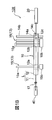
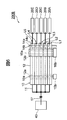
- FIG. 1A is a diagram showing a schematic configuration of a culture apparatus 100 according to Embodiment 1 of the present invention.
- FIG. 1B is a side view of the culture apparatus 100 shown in FIG. 1A.
- the culture apparatus 100 of this embodiment includes a flow path unit 10 and a culture container 20.
- the culture vessel 20 is not particularly limited as long as it can cultivate cells. For example, a general dish, multiwell plate, flask, tube, or other vessel used in the field of regenerative medicine may be used. it can.
- the inner surface of the culture vessel 20 is subjected to a surface treatment suitable for cell culture, and has transparency that allows the inside to be visually recognized.
- the culture apparatus 100 also includes a cell container 30 that stores the cell suspension CS supplied to the culture container 20, a culture medium container 40 that stores the culture medium CM supplied to the culture container 20, and waste liquid discharged from the culture container 20.
- a waste liquid container 50 for accommodating WL can be provided.
- the culture apparatus 100 can include a gas supply unit 60 that supplies the mixed gas MG to the culture vessel 20 and a gas recovery unit 70 that recovers the exhaust gas EG discharged from the culture vessel 20.
- the gas supply unit 60 supplies a mixed gas MG having a predetermined CO 2 concentration, such as a mixed gas MG having a CO 2 concentration of about 5%.
- the flow path unit 10 is a unit for supplying a fluid containing liquid and gas to the culture vessel 20 or discharging it from the culture vessel 20. More specifically, the flow path unit 10 uses, for example, a fluid such as the cell suspension CS from the cell container 30, the medium CM from the medium container 40, and the mixed gas MG from the gas supply unit 60. To supply. In addition, the flow path unit 10 discharges the fluid such as the exhaust gas EG and the waste liquid WL from the culture container 20 to the gas recovery unit 70 and the waste liquid container 50, respectively.
- a fluid such as the cell suspension CS from the cell container 30, the medium CM from the medium container 40, and the mixed gas MG from the gas supply unit 60.
- the flow path unit 10 discharges the fluid such as the exhaust gas EG and the waste liquid WL from the culture container 20 to the gas recovery unit 70 and the waste liquid container 50, respectively.
- the flow path unit 10 includes a tube flow path 11 through which a fluid passes and a flow path base 12 that supports the tube flow path 11.
- the tube flow path 11 and the flow path base 12 constitute a single flow path layer L.
- the flow path unit 10 includes a flow rate control mechanism 13 that controls the flow rate of the fluid by sandwiching the tube flow path 11 between the flow path base 12 and a positioning mechanism 14 that positions the flow path base 12. ing.
- the flow path unit 10 of this embodiment includes a valve mechanism 15 and a tube pump 16 as the flow rate control mechanism 13.
- the tube flow path 11 can be made of an elastic resin material such as silicone rubber.
- a commercially available tube flow path 11 that conforms to applicable laws and regulations, such as the Pharmaceutical Affairs Law, can be used. It is preferable that the tube flow path 11 has the transparency which can visually recognize the fluid which flows through the inside.
- a fluid supply tube channel 11 a and fluid discharge tube channels 11 b and 11 c are connected to the culture vessel 20.
- One end of the fluid supply tube channel 11 a is connected to the culture vessel 20.
- One end of the fluid supply tube channel 11a of the channel unit 10 may be aseptically connected to the tube channel connected to the culture vessel 20 via a sterilization connection.
- one end of the tube channels 11b and 11c for discharging the fluid of the channel unit 10 may be aseptically connected to the tube channel connected to the culture vessel 20 via the sterilization connection part.
- the other end of the tube channel 11a for fluid supply of the channel unit 10 is a tube channel 11d for cell suspension supply, a tube channel 11e for medium supply, and a tube channel 11f for mixed gas supply.
- the tube flow path 11 d for supplying the cell suspension of the flow path unit 10 is aseptically connected to the tube flow path 11 connected to the cell container 30 via the sterilization connection portion 17.
- the medium supply tube flow path 11 e of the flow path unit 10 is aseptically connected to the tube flow path 11 connected to the medium container 40 via the sterilization connection portion 17.
- the mixed gas supply tube flow path 11 f of the flow path unit 10 is connected to the tube flow path 11 connected to the gas supply unit 60 via the filter 18.
- the filter 18 for example, a filter that can prevent bacteria from entering the culture vessel 20 can be used.
- the tube channels 11b and 11c for discharging the fluid of the channel unit 10 include a tube channel 11b for discharging gas and a tube channel 11c for discharging waste liquid, which are provided separately.
- One end of the gas discharge tube channel 11 b is connected to the culture vessel 20, and the other end is connected to the gas recovery unit 70.
- the tube channel 11c for discharging the waste liquid has one end connected to the culture container 20 and the other end connected to the waste liquid container 50.
- the tube flow path 11 b for gas discharge of the flow path unit 10 is connected to the tube flow path 11 connected to the gas recovery unit 70 via the filter 18.
- the filter 18 for example, the same filter as the filter 18 provided in the mixed gas supply tube channel 11 f can be used.
- the tube flow path 11c for discharging the waste liquid of the flow path unit 10 may be aseptically connected to the tube flow path 11 connected to the waste liquid container 50 via the aseptic connection portion.
- the channel base 12 is, for example, a rectangular plate-like member in plan view, and supports the tube channels 11a, 11d, 11e, and 11f for supplying fluid and the tube channels 11b and 11c for discharging fluid. .
- the tube flow paths 11a to 11f described above are simply referred to as the tube flow path 11 when it is not necessary to distinguish them.
- the flow path base 12 can be manufactured by, for example, a resin material in which the tube flow path 11 is embedded.
- the flow path base 12 is preferably made of, for example, a resin material that has transparency that transmits visible light and that transmits ultraviolet rays, ⁇ rays, and the like for sterilizing the flow path unit 10.
- the flow path base 12 of the present embodiment has through holes 12a and 12b in which the valve mechanism 15 that is the flow rate control mechanism 13 and the tube pump 16 are disposed.
- the through hole 12a for the valve mechanism includes a medium supply tube flow path 11e embedded in the flow path base 12, a cell suspension supply tube flow path 11d, a mixed gas supply tube flow path 11f, and a gas.
- the discharge tube channels 11b are respectively provided at positions where they are partially exposed on the inner peripheral surface of the through-hole 12a.
- the flow path base 12 sandwiches the tube flow path 11 between the inner wall of the valve mechanism through hole 12 a and the valve mechanism 15.
- the through hole 12b for the tube pump is a position at which the tube channel 11a for supplying fluid embedded in the channel base 12 and the tube channel 11c for discharging waste liquid are partially exposed in the through hole 12b. Is provided.
- the flow path base 12 sandwiches the tube flow path 11 a for supplying fluid between the inner wall of the tube pump through hole 12 b and the tube pump 16. Further, the flow path base 12 sandwiches a tube flow path 11c for discharging the waste liquid between the inner wall of the tube pump through hole 12b and the tube pump 16.
- the valve mechanism 15 is a flow rate control mechanism 13 that controls the flow rate of the fluid by holding the tube flow path 11 between the flow path base 12.
- the valve mechanism 15 includes, for example, a columnar valve body 15a extending in a direction penetrating the flow path base 12, and a valve body driving unit 15b that rotates the valve body 15a in a range of, for example, 0 ° to 90 °. Yes.
- the valve body drive part 15b can be comprised by a motor, a reduction gear, etc., for example.
- the valve body 15a extends in a direction penetrating the flow path base 12 and intersects the tube flow paths 11b, 11d, 11e, and 11f extending along the flow path base 12 substantially perpendicularly.
- each valve body 15a when the valve body 15a is at an angle of 0 °, the tip of each valve body 15a presses each of the tube flow paths 11b, 11d, 11e, and 11f against the flow path base 12. Thereby, each valve body 15a crushes and closes each of the tube flow paths 11b, 11d, 11e, and 11f from the outside.
- each valve body 15a rotates to an angle of 90 °, the tip of each valve body 15a is separated from the tube flow paths 11b, 11d, 11e, and 11f, and the tube flow paths 11b, 11d, 11e, and 11f are opened. To do.
- the plurality of valve mechanisms 15 that are the flow rate control mechanisms 13 narrow and open the tube flow paths 11b, 11d, 11e, and 11f with the flow path base 12 to thereby open the tube flow paths 11b, 11d, 11e, and 11f. Is opened and closed to control the flow rate of the fluid flowing through the tube channels 11b, 11d, 11e, and 11f.
- the through hole 12a for the valve mechanism of the flow path base 12 is formed in a long hole shape having a width W1 that does not hinder the rotation of the valve body 15a.
- the through hole 12a for the valve mechanism has a round shape in which the direction along the extending direction of the tube flow path 11 is the short direction, and the direction perpendicular to the short direction and along the flow path base 12 is the long direction. It is a long hole.
- the dimension of the through-hole 12a for the valve mechanism in the short direction, that is, the width W1 of the through-hole 12a makes it easy to insert the valve body 15a and allows the flow path base 12 to move along the width direction of the through-hole 12a. It is preferable to set the width W1 that can be regulated within a wide range.
- the longitudinal dimension of the through hole 12a for the valve mechanism that is, the length L1 of the through hole 12a is preferably set to a length L1 that does not hinder the operation of the flow path base 12 when the flow path unit 10 is installed.
- the operation of the flow path base 12 refers to the movement of the flow path base 12 in the longitudinal direction of the through hole 12a after each valve body 15a is inserted into the through hole 12a, and each valve body 15a is moved to the tube flow path 11b.
- 11d, 11e, and 11f, and the tube flow paths 11b, 11d, 11e, and 11f are sandwiched between the valve bodies 15a and the flow path base 12, respectively.
- the tube pump 16 is a flow rate control mechanism 13 that controls the flow rate of fluid by sandwiching the tube flow paths 11 a and 11 c between the flow path base 12.
- the tube pump 16 includes a roller 16a that rotates while squeezing the tube flow paths 11a and 11c, and a roller drive unit 16b that drives the roller 16a.
- the roller drive part 16b can be comprised by a motor, a reduction gear, etc., for example.
- Each roller 16 a extends in a direction in which the central axis passes through the flow path base 12, and intersects the tube flow paths 11 a and 11 c along the flow path base 12 substantially vertically.
- Each of the rollers 16a driven by the roller driving unit 16b rotates around the central axis, and rotates while compressing the tube flow paths 11a and 11c sandwiched between the flow path base 12 and the tube flow.
- the channels 11a and 11c are handled and the fluid in the tube channels 11a and 11c is pumped in the rotation direction of the roller 16a. That is, the tube pump 16 is a flow rate control mechanism 13 that squeezes the tube flow paths 11a and 11c with the flow path base 12 to pump the fluid flowing through the tube flow paths 11a and 11c.
- the through hole 12b for the tube pump of the flow path base 12 is formed in an oblong hole shape having a width W2 that does not hinder the rotation of the roller 16a. More specifically, the through hole 12b for the tube pump has a round shape in which the direction along the extending direction of the tube flow path 11 is the short direction, and the direction perpendicular to the short direction and along the flow path base 12 is the long direction. It is a long hole.
- the dimension in the short direction of the through hole 12b for the tube pump that is, the width W2 of the through hole 12b makes it easy to insert the tube pump 16 and allows the passage base 12 to move along the width direction of the through hole 12b. It is preferable to set the width W2 that can be regulated within a wide range.
- the longitudinal dimension of the through hole 12b for the tube pump that is, the length L2 of the through hole 12b can be set to a length that does not hinder the operation of the flow path base 12 when the flow path unit 10 is installed. preferable.
- the operation of the flow path base 12 is to move the flow path base 12 in the longitudinal direction of the through hole 12b after inserting the tube pump 16 into the through hole 12b, and to move each tube pump 16 to the tube flow paths 11a and 11c. And the tube flow paths 11a and 11c are sandwiched between the tube pumps 16 and the flow path base 12, respectively.
- the positioning mechanism 14 for positioning the flow path base 12 includes a long hole 14a provided in the flow path base 12, and a columnar shape that is inserted into the long hole 14a and can move relative to the flow path base 12 in the longitudinal direction of the long hole 14a. And a lock member 14c that restricts relative movement between the columnar portion 14b and the flow path base 12.
- the columnar portion 14b has a columnar shape
- the long hole 14a has an elongated round hole formed in a semi-cylindrical shape whose both ends in the longitudinal direction are slightly larger in diameter than the diameter of the columnar portion 14b. It is.
- the columnar part 14b is fixed to the base of the culture apparatus 100, etc.
- the flow path base 12 is provided to be movable relative to the columnar part 14b in the longitudinal direction of the long hole 14a. ing.
- the lock member 14c is a pin-like member that is inserted into the horizontal hole 12c provided in the flow path base 12 and crosses the long hole 14a in the width direction.
- the lock member 14 c is inserted into the lateral hole 12 c of the flow path base 12, thereby restricting relative movement between the columnar portion 14 b and the flow path base 12.
- the flow path base 12 sandwiches the tube flow path 11 between the flow control mechanism 13 and an open position where the flow path control mechanism 13 opens the tube flow path 11. It is positioned at a fixed position.
- one end of a tube path 11a for supplying fluid, one end of a tube path 11c for discharging waste liquid, and one end of a tube path 11b for discharging gas are provided in the culture vessel 20. Connected in advance. Further, at the other end of the tube channel 11a for supplying fluid, that is, at the end of the tube channel 11e for supplying medium, the tube channel 11d for supplying cell suspension, and the tube channel 11f for supplying mixed gas.
- the sterilization connection part 17, the sterilization connection part 17, and the filter 18 are connected in advance.
- a filter 18 is connected in advance to the other end of the gas discharge tube flow path 11b, and a waste liquid container 50 is connected in advance to the other end of the waste liquid discharge tube flow path 11c.
- the flow path unit 10, the culture container 20, the sterilization connection unit 17, the filter 18, and the waste liquid container 50 are sterilized by, for example, ultraviolet rays or ⁇ rays in a state of being connected in advance as described above.
- a tube flow path connected to the cell container 30 is connected to the sterilization connection portion 17 of the tube flow path 11d for supplying the cell suspension of the flow path unit 10.
- 11 sterilization connections 17 are connected.
- the sterilization connection portion 17 of the tube flow path 11 connected to the culture medium container 40 is connected to the sterilization connection portion 17 connected to the medium flow tube supply path 11 e of the flow path unit 10.
- the tube 18 connected to the gas supply unit 60 is connected to the filter 18 connected to the tube flow path 11 f for supplying the mixed gas of the flow path unit 10, and the gas discharge tube of the flow path unit 10 is connected.
- the tube flow path 11 connected to the gas recovery unit 70 is connected to the filter 18 connected to the flow path 11b.
- valve body 15a of the valve mechanism 15 provided in the tube flow path 11d for supplying the cell suspension is rotated 90 ° by the valve drive section 15b to open the tube flow path 11d for supplying the cell suspension.
- the tube pump 16 provided in the tube channel 11a for supplying fluid is driven.
- the cell suspension CS is introduced from the cell container 30 to the culture container 20 through the tube flow path 11d for supplying the cell suspension and the tube flow path 11a for supplying the fluid, and seeded.
- the valve body 15a of the valve mechanism 15 provided in the cell flow path 11d for supplying the cell suspension is rotated 90 ° in the reverse direction by the valve drive section 15b to supply the tube flow path 11d for supplying the cell suspension. Close.
- valve body 15a of the valve mechanism 15 provided in the tube passage 11f for supplying the mixed gas is rotated by 90 ° by the valve body driving portion 15b to open the tube passage 11f for supplying the mixed gas, thereby supplying the fluid.
- the tube pump 16 provided in the tube flow path 11a is driven. Accordingly, the mixed gas MG can be intermittently or continuously supplied from the gas supply unit 60 to the culture vessel 20 through the mixed gas supply tube channel 11f and the fluid supply tube channel 11a.
- valve body 15a of the valve mechanism 15 provided in the gas discharge tube channel 11b is rotated by 90 ° by the valve body driving unit 15b to open the gas discharge tube channel 11b.
- the gas in the culture container 20 can be discharged
- the tube pump 16 provided in the tube channel 11a for fluid supply is stopped. Further, the valve body 15a of the valve mechanism 15 provided in the tube passage 11f for supplying mixed gas is rotated 90 ° in the reverse direction by the valve body driving portion 15b to close the tube passage 11f for supplying mixed gas. Further, the valve body 15a of the valve mechanism 15 provided in the gas discharge tube flow path 11b may be rotated 90 ° in the reverse direction by the valve body drive unit 15b to close the gas discharge tube flow path 11b. .
- the valve body 15a of the valve mechanism 15 provided in the medium supply tube channel 11e is rotated by 90 ° by the valve body drive unit 15b to supply the culture medium.
- the tube flow path 11e is opened, and the tube pump 16 provided in the tube flow path 11a for supplying fluid is driven.
- the medium CM can be intermittently or continuously supplied from the medium container 40 to the culture container 20 through the medium supply tube channel 11e and the fluid supply tube channel 11a.
- the tube pump 16 provided in the tube flow path 11c for discharging the waste liquid is driven.
- the waste liquid WL containing the waste can be discharged from the culture container 20 to the waste liquid container 50 intermittently or continuously through the tube flow path 11c for discharging the waste liquid.
- the tube pump 16 provided in the tube channel 11a for fluid supply is stopped. Further, the valve body 15a of the valve mechanism 15 provided in the medium supply tube flow path 11d is rotated by 90 ° in the reverse direction by the valve element drive unit 15b to close the medium supply tube flow path 11d. Further, the tube pump 16 provided in the tube flow path 11c for discharging the waste liquid is stopped.
- the supply of the mixed gas MG to the culture vessel 20 and the discharge of the gas in the culture vessel 20 and the supply of the medium CM to the culture vessel 20 and the discharge of the waste liquid WL in the culture vessel 20 are periodically performed. Can be done automatically.
- the culture apparatus 100 of the present embodiment it is possible to automatically perform cell culture in a closed system, which is conventionally performed manually and in an open system by a pipette operation or the like.
- the risk of contamination is reduced, and various cells such as floating cells and adherent cells that need to be periodically replaced with a medium CM containing nutrients.
- the culture can be automated.
- the culture apparatus 100 according to the present embodiment is particularly effective for culturing cells that require a short time for metabolism and require medium replacement frequently.
- FIG. 2A and 2B are plan views for explaining the installation procedure of the flow path unit 10 shown in FIG. 1A.
- the valve mechanism 15 that is the flow rate control mechanism 13 and the tube pump are disposed at predetermined positions on the base for installing the flow path unit 10. 16 and the columnar part 14b of the positioning mechanism 14 are installed.
- a rack for supporting the flow path base 12 may be installed on a base for installing the flow path unit 10.
- the valve body 15a of the valve mechanism 15 is inserted into the through hole 12a for the valve mechanism of the flow path base 12, the through hole 12b for the tube pump 16, and the long hole 14a of the positioning mechanism 14, respectively.
- the roller 16a of the tube pump 16 and the columnar portion 14b of the positioning mechanism 14 are inserted.
- the flow path base 12 may be supported by a rack provided on a base for installing the flow path unit 10.
- the flow path base 12 is positioned by the positioning mechanism 14 to an open position where the tube flow path 11 between the valve mechanism 15 and the tube pump 16 as the flow rate control mechanism 13 is opened.
- the flow path base 12 moves relative to the columnar part 14b of the positioning mechanism 14 in the longitudinal direction of the long hole 14a.
- the flow path base 12 is positioned at the fixed position shown in FIG. 2B.
- the flow path base 12 holds the tube flow path 11 between the valve body 15a of the valve mechanism 15 that is the flow rate control mechanism 13 and the roller 16a of the tube pump 16 at a fixed position.
- the flow path base 12 is fixed by inserting the locking member 14 c of the positioning mechanism 14 into the lateral hole 12 c of the flow path base 12.
- the flow path base 12 is opened by the positioning mechanism 14 to open the tube flow path 11 between the valve mechanism 15 and the tube pump 16 that are the flow rate control mechanism 13. And a fixed position where the tube flow path 11 is sandwiched between the valve mechanism 15 and the tube pump 16.
- the installation work of the flow path unit 10 is completed only by moving the flow path base 12 from the open position to the fixed position. That is, the flow path base 12 is moved from the open position relative to the columnar portion 14 b of the positioning mechanism 14 in the longitudinal direction of the long hole 14 a to be positioned at the fixed position, and the lock member is inserted into the flow path base 12. Only the installation work of the flow path unit 10 is completed.
- valve for the tube flow path 11e for supplying the culture medium, the tube flow path 11d for supplying the cell suspension, the tube flow path 11f for supplying the mixed gas, and the tube flow path 11b for discharging the gas from the culture vessel 20 are provided.
- the attachment of the mechanism 15 and the attachment of the tube pump 16 to the tube passage 11a for supplying fluid and the tube passage 11c for discharging waste liquid can be performed by two simple operations.
- the flow path unit 10 of the present embodiment uses the tube flow path 11 as a flow path for supplying or discharging a fluid. Therefore, for example, by using a commercially available tube channel 11 used for cell culture, the surface treatment of the channel required in the conventional microchannel chip described in Patent Document 2 can be omitted. it can. Therefore, it is possible to provide the flow path unit 10 that does not require the surface treatment of the flow path and the culture apparatus 100 using the same.
- the flow path base 12 has through holes 12a and 12b in which the valve mechanism 15 as the flow rate control mechanism 13 and the tube pump 16 are arranged, and the inner walls of the through holes 12a and 12b.
- the tube flow path 11 is sandwiched between the valve mechanism 15 and the tube pump 16.
- the flow path base 12 is positioned at a predetermined position by inserting the valve mechanism 15 and the tube pump 16 through the through holes 12a and 12b, and the flow path base 12 can be easily installed.
- the flow path unit 10 of this embodiment includes a flow rate control mechanism 13 that controls the flow rate of the fluid by sandwiching the tube flow path 11 between the flow path base 12.
- the flow path unit 10 includes, as the flow rate control mechanism 13, a valve mechanism 15 that narrows the tube flow path 11 between the flow path base 12 and controls the flow rate of fluid, and a flow path base 12. And a tube pump 16 that squeezes the tube flow path 11 to pump the fluid.
- the positioning mechanism 14 has a long hole 14a provided in the flow path base 12, and is inserted into the long hole 14a so as to be relative to the flow path base 12 in the longitudinal direction of the long hole 14a.
- a columnar portion 14b that can move, and a lock member 14c that restricts relative movement between the columnar portion 14b and the flow path base 12 are provided. Thereby, the moving direction of the flow path base 12 can be restricted to the longitudinal direction of the long hole 14a, and the flow path base 12 can be easily installed.
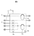
- FIG. 3 is a plan view for explaining an example of a manufacturing method of the flow path base 12 shown in FIGS. 1A to 2B.
- the tube flow path 11 is placed in advance in a mold or a mold having a cavity corresponding to the shape of the flow path base 12, and a plasticized resin material is injected. Harden.
- a part of the tube flow path 11 to be exposed in the through hole of the flow path base 12 is previously exposed to a cylindrical part of a mold or a mold for forming the through holes 12a and 12b.
- the flow path base 12 in which the tube flow path 11 is embedded can be obtained.
- one end of the tube flow path 11 is closed with the clip C, and the other end is closed with the clip C in a state where air or water is injected from the other end. Also good. Thereby, it can prevent that the flexible tube flow path 11 which has elasticity receives the pressure from a resin material, and is crushed.
- the flow path base 12 is made of a resin material in which the tube flow path 11 is embedded.
- the tube flow path 11 can be integrated and supported by the flow path base 12, but also the flow path base 12 having a complicated shape can be easily manufactured.
- the use of a relatively inexpensive resin material can reduce the manufacturing cost of the flow path unit 10 and can be discarded after a single use.
- the resin material of the flow path base 12 is desirably a material that has high moisture resistance and can be sterilized. Thereby, the flow path unit 10 can be applied to physicochemical use and regenerative medical use.
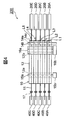
- FIG. 4 is a side view showing a schematic configuration of the culture apparatus 200 according to Embodiment 2 of the present invention.
- the culture apparatus 200 of the present embodiment is different from the culture apparatus 100 described in the first embodiment in that the flow path unit 10 includes a plurality of flow path layers L1 to L5. Since the other configuration of the culture device 200 of the present embodiment is the same as that of the culture device 100 described in the first embodiment, the same portions are denoted by the same reference numerals and description thereof is omitted.
- the flow path unit 10 includes a plurality of flow path layers L1 to L5.
- Each of the plurality of flow path layers L1 to L5 includes a tube flow path 11 and a flow path base 12.
- the valve mechanism 15 and the tube pump 16 that are the flow rate control mechanism 13 are arranged so as to penetrate the through holes 12a and 12b of the plurality of flow path layers L1 to L5.
- the flow path unit 10 and the culture apparatus 200 including the same it is possible to simultaneously culture different types of cells by the closed flow path layers L1 to L5. That is, it is possible to prevent contamination of the heterogeneous cells in each of the flow path layers L1 to L5 and simultaneously culture a plurality of heterogeneous cells with one culture apparatus 200.
- different patient cells can be cultured in the culture vessels 20A to 20E of the flow path layers L1 to L5, and the productivity of cell culture in regenerative medicine can be improved.
- the valve mechanism 15 and the tube pump 16 that are the flow rate control mechanism 13 can be shared by the plurality of flow path layers L1 to L5, and the configuration of the flow path unit 10 and the culture apparatus 200 is simplified.
- the culture apparatus 200 can be reduced in size.
- FIG. 5 is a side view showing Modification 1 of the culture apparatus 200 of the present embodiment shown in FIG.
- the culture device 200A of the first modification includes three flow path layers L1 to L3.
- the culture apparatus 200 of Embodiment 2 can freely increase or decrease the number of the flow path layers L1 to L5. Therefore, by increasing or decreasing the number of flow path layers L1 to L5 according to demand, the amount of cells to be cultured can be adjusted, and the operating flexibility of the culture apparatus 200 can be improved.
- FIG. 6 is a side view showing Modification Example 2 of the culture apparatus 200 of the present embodiment shown in FIG.
- each of the plurality of flow path layers L1 to L5 described above is connected to one common medium container 40.
- the same type of cells can be cultured simultaneously in the culture containers 20A to 20E connected to the flow path layers L1 to L5 of the flow path unit 10.
- the culture apparatus 200B of the present modification can be applied to simultaneous and mass culture of cells including iPS cells that repeatedly pass through the same type of cells.
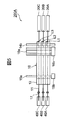
- FIG. 7 is a diagram showing a schematic configuration of a culture apparatus 300 according to Embodiment 3 of the present invention.
- the culture apparatus 300 according to the present embodiment is different from the culture apparatus 200 described in the above-described second embodiment in that an incubator 81, a temperature control unit 82, and a control unit 83 are provided. Since the other points of the culture apparatus 300 of the present embodiment are the same as those of the culture apparatus 200 of the second embodiment, the same parts are denoted by the same reference numerals and description thereof is omitted.
- the culture apparatus 300 of the present embodiment includes an incubator 81 that accommodates the culture containers 20A to 20E and a temperature control unit 82 that controls the internal temperature of the incubator 81.
- the culture apparatus 300 includes a control unit 83 that controls the valve mechanism 15 and the tube pump 16 that are the flow rate control mechanism 13 and the temperature control unit 82.
- the valve body drive unit 15 b of the valve mechanism 15, the roller drive unit 16 b of the tube pump 16, and the temperature control unit 82 are each connected to the control unit 83 by a signal line 84 and are controlled by a control signal from the control unit 83.
- control unit 83 for example, a control terminal such as a personal computer including a calculation unit such as a CPU, a storage unit such as a memory, an input / output unit such as a keyboard, a display unit such as a liquid crystal display screen, and the like can be used.
- the culture apparatus 300 may include a microscope that images the cells in the individual culture containers 20A to 20E, and may input an image of the microscope to the control unit 83 or transmit it to a server via a network. Further, the image of the microscope may be image-processed by various image processing software.
- the same effects as those of the culture device 100 of the first embodiment and the culture device 200 of the second embodiment can be obtained.
- the closed-system channel unit 10 is used, and from the culture vessels 20 A of the plurality of channel layers L 1 to L 5 according to the program of the controller 83. 20E makes it possible to automatically cultivate many types of cells or the same type of cells simultaneously. Therefore, according to the culture apparatus 300 of this embodiment, the productivity of cell culture can be improved, and more uniform and higher culture quality can be obtained.
- the channel unit positioning mechanism is not limited to the configuration described in the above-described embodiment as long as the channel base can be positioned.
- the supply of the culture medium and the mixed gas to the culture vessel and the discharge of the gas and the waste liquid from the culture vessel have been described.
- other fluids can be supplied and discharged.
- a cleaning solution or a peeling enzyme that peels cells can be introduced into the culture vessel via the flow channel unit, or a cell suspension can be recovered from the culture vessel. May be.
- the example in which the flow path base of the flow path unit is installed along the horizontal direction has been described.
- the channel base may be installed along the vertical direction, or may be installed in a state inclined at a predetermined angle with respect to the horizontal direction or the vertical direction.
- a configuration in which a plurality of flow path layers are separated has been described.
- a plurality of flow path layers may be provided integrally.
- three flow path layers may be provided integrally, or two flow path layers may be provided integrally.
Landscapes
- Engineering & Computer Science (AREA)
- Chemical & Material Sciences (AREA)
- General Engineering & Computer Science (AREA)
- Organic Chemistry (AREA)
- Health & Medical Sciences (AREA)
- Life Sciences & Earth Sciences (AREA)
- Bioinformatics & Cheminformatics (AREA)
- Wood Science & Technology (AREA)
- Mechanical Engineering (AREA)
- Biotechnology (AREA)
- Zoology (AREA)
- Chemical Kinetics & Catalysis (AREA)
- Microbiology (AREA)
- Sustainable Development (AREA)
- Biomedical Technology (AREA)
- Medicinal Chemistry (AREA)
- Biochemistry (AREA)
- General Health & Medical Sciences (AREA)
- Genetics & Genomics (AREA)
- Apparatus Associated With Microorganisms And Enzymes (AREA)
Abstract
従来よりも設置を容易にすることができ、流路の表面処理が不要な流路ユニット及びそれを用いた培養装置を提供する。本発明の流体ユニットは、流体を通すチューブ流路と、該チューブ流路を支持する流路ベースと、該流路ベースとの間に前記チューブ流路を挟持して前記流体の流量制御を行う流量制御機構と、前記流路ベースを位置決めする位置決め機構と、を備える。流路ベースは、位置決め機構によって、流量制御機構との間の前記チューブ流路を開放する開放位置と、前記流量制御機構との間に前記チューブ流路を挟持する固定位置とに位置決めされる。
Description
本発明は、流路ユニット及び培養装置に関する。
従来から、細胞又は組織を自動操作により培養する培養装置が知られている(例えば、下記特許文献1を参照)。特許文献1に記載された細胞培養装置は、細胞に用いる溶液を保持する溶液保持部と、前記溶液保持部と複数の培養容器とをそれぞれ接続させる複数の流路とを備えている。前記複数の流路は、溶液保持部から前記複数の培養容器それぞれまでの長さが等しい。
また、マイクロ流路チップと、これを用いた医療用測定装置に関する発明が開示されている(例えば、下記特許文献2を参照)。特許文献2に記載されたマイクロチップ流路は、表面に、互いに接続されていない少なくとも2筋の溝を有する第1基板と、前記第1基板の表面に積層状態に重ね合わされた第2基板とを備える。前記第1基板の表面の溝は、前記第2基板によって蓋がされ、蓋がされた溝によってマイクロ流路が構成されている。
特許文献2のマイクロ流路チップにおいて、前記第1基板は弾性材料で構成されている。また、前記第一基板の裏面側から、前記各溝に貫通する少なくとも2つの貫通孔が形成されている。そして、前記2つの貫通孔に挿入されて貫通孔と結合し、前記マイクロ流路の開閉を制御するためのバルブが、前記第1基板の裏面側に備えられている。
特許文献1に記載された細胞培養装置によれば、高品質な培養が可能となる。しかし、特許文献1の図2に示されるような複雑な流路回路を実現するためには、流路部が備える複数のチューブポンプ、電磁弁、回転式弁機構等のそれぞれに対し、順次、流路チューブを嵌め込む必要があり、設置作業が煩雑になる。
一方、特許文献2に記載されたマイクロ流路チップによれば、少なくとも2筋の溝とバルブとにより開閉可能な流路を構成することで、マイクロ流路チップにバルブ機能を付与してバルブを設ける手間を軽減することができる。このようなマイクロ流路チップを細胞の培養に用いるためには、例えば、流路に対する表面処理が必要になる。しかし、前記流路に対する均一な表面処理は困難であり、析出物が発生する虞もある。
本発明は、前記課題に鑑みてなされたものであり、従来よりも設置を容易にすることができ、流路の表面処理が不要な流路ユニット及びそれを用いた培養装置を提供することを目的とする。
前記目的を達成するために、本発明の流路ユニットは、流体を供給又は排出するための流路ユニットであって、前記流体を通すチューブ流路と、該チューブ流路を支持する流路ベースと、該流路ベースとの間に前記チューブ流路を挟持して前記流体の流量制御を行う流量制御機構と、前記流路ベースを位置決めする位置決め機構と、を備え、前記流路ベースは、前記位置決め機構によって、前記流量制御機構との間の前記チューブ流路を開放する開放位置と、前記流量制御機構との間に前記チューブ流路を挟持する固定位置とに位置決めされることを特徴とする。
本発明によれば、従来よりも設置を容易にすることができ、流路の表面処理が不要な流路ユニット及びそれを用いた培養装置を提供することができる。
以下、図面を参照して本発明の流路ユニット及びそれを備えた培養装置の実施形態について説明する。
[実施形態1]
図1Aは、本発明の実施形態1に係る培養装置100の概略構成を示す図である。図1Bは、図1Aに示す培養装置100の側面図である。本実施形態の培養装置100は、流路ユニット10と培養容器20とを備えている。培養容器20は、細胞を培養することができる容器であれば特に限定されないが、例えば、再生医療の分野で用いられる一般的なディッシュ、マルチウェルプレート、フラスコ、チューブ、その他の容器を用いることができる。一般に、培養容器20の内表面には、細胞の培養に適した表面処理が施され、内部を視認できる透明性を有している。
図1Aは、本発明の実施形態1に係る培養装置100の概略構成を示す図である。図1Bは、図1Aに示す培養装置100の側面図である。本実施形態の培養装置100は、流路ユニット10と培養容器20とを備えている。培養容器20は、細胞を培養することができる容器であれば特に限定されないが、例えば、再生医療の分野で用いられる一般的なディッシュ、マルチウェルプレート、フラスコ、チューブ、その他の容器を用いることができる。一般に、培養容器20の内表面には、細胞の培養に適した表面処理が施され、内部を視認できる透明性を有している。
また、培養装置100は、培養容器20に供給する細胞懸濁液CSを収容する細胞容器30、培養容器20に供給する培地CMを収容する培地容器40、及び、培養容器20から排出された廃液WLを収容する廃液容器50を備えることができる。さらに、培養装置100は、培養容器20に混合ガスMGを供給するガス供給部60、及び培養容器20から排出された排出ガスEGを回収するガス回収部70を備えることができる。ガス供給部60は、例えば5%程度のCO2濃度の混合ガスMG等、所定のCO2濃度の混合ガスMGを供給する。
流路ユニット10は、液体及び気体を含む流体を、培養容器20に供給し、又は、培養容器20から排出するためのユニットである。より具体的には、流路ユニット10は、例えば、細胞容器30からの細胞懸濁液CS、培地容器40からの培地CM、及びガス供給部60からの混合ガスMG等の流体を培養容器20に供給する。また、流路ユニット10は、例えば、培養容器20から排出ガスEG及び廃液WL等の流体をそれぞれガス回収部70及び廃液容器50へ排出する。
流路ユニット10は、流体を通すチューブ流路11と、該チューブ流路11を支持する流路ベース12とを備えている。本実施形態の流路ユニット10では、チューブ流路11と流路ベース12とによって、単層の流路層Lが構成されている。また、流路ユニット10は、流路ベース12との間にチューブ流路11を挟持して流体の流量制御を行う流量制御機構13と、流路ベース12を位置決めする位置決め機構14と、を備えている。本実施形態の流路ユニット10は、流量制御機構13として弁機構15及びチューブポンプ16を備えている。
チューブ流路11は、例えばシリコーンゴム等、弾性を有する樹脂材料によって製作することができる。培養装置100及び流路ユニット10を再生医療の分野で使用する場合には、例えば薬事法等、適用される法規制に適合した市販のチューブ流路11を用いることができる。チューブ流路11は、内部を流れる流体を視認できる透明性を有することが好ましい。
本実施形態の培養装置100では、培養容器20に対して流体供給用のチューブ流路11aと、流体排出用のチューブ流路11b,11cとが接続されている。流体供給用のチューブ流路11aの一端は、培養容器20に接続されている。なお、流路ユニット10の流体供給用のチューブ流路11aの一端は、滅菌接続部を介して、培養容器20に接続されたチューブ流路と無菌的に接続されていてもよい。同様に、流路ユニット10の流体排出用のチューブ流路11b,11cの一端は、滅菌接続部を介して、培養容器20に接続されたチューブ流路と無菌的に接続されていてもよい。
流路ユニット10の流体供給用のチューブ流路11aの他端は、細胞懸濁液供給用のチューブ流路11dと、培地供給用のチューブ流路11eと、混合ガス供給用のチューブ流路11fとに分岐され、それぞれ細胞容器30と、培地容器40と、ガス供給部60とに接続されている。より詳細には、流路ユニット10の細胞懸濁液供給用のチューブ流路11dは、細胞容器30に接続されたチューブ流路11に、滅菌接続部17を介して無菌的に接続されている。同様に、流路ユニット10の培地供給用のチューブ流路11eは、培地容器40に接続されたチューブ流路11に、滅菌接続部17を介して無菌的に接続されている。また、流路ユニット10の混合ガス供給用のチューブ流路11fは、ガス供給部60に接続されたチューブ流路11にフィルタ18を介して接続されている。フィルタ18は、例えば、培養容器20への細菌の侵入等を防止できるものを用いることができる。
流路ユニット10の流体排出用のチューブ流路11b,11cは、個別に設けられたガス排出用のチューブ流路11bと、廃液排出用のチューブ流路11cとを含んでいる。ガス排出用のチューブ流路11bは、一端が培養容器20に接続され、他端がガス回収部70に接続されている。廃液排出用のチューブ流路11cは、一端が培養容器20に接続され、他端が廃液容器50に接続されている。また、流路ユニット10のガス排出用のチューブ流路11bは、ガス回収部70に接続されたチューブ流路11に、フィルタ18を介して接続されている。フィルタ18は、例えば、混合ガス供給用のチューブ流路11fに設けられたフィルタ18と同様のものを用いることができる。なお、流路ユニット10の廃液排出用のチューブ流路11cは、廃液容器50に接続されたチューブ流路11に、無菌接続部を介して無菌的に接続されていてもよい。
流路ベース12は、例えば、平面視で矩形の板状の部材であり、流体供給用のチューブ流路11a,11d,11e,11f及び流体排出用のチューブ流路11b,11cを支持している。なお、以下の説明において、前述したチューブ流路11aから11fを特に区別する必要がない場合には、単にチューブ流路11と表記する。流路ベース12は、例えば、チューブ流路11を埋め込んだ樹脂材料によって製作することができる。流路ベース12は、例えば、可視光を透過する透明性を有し、流路ユニット10を滅菌するための紫外線、γ線等を透過する樹脂材料によって製作することが好ましい。
本実施形態の流路ベース12は、流量制御機構13である弁機構15及びチューブポンプ16を配置する貫通孔12a,12bを有している。弁機構用の貫通孔12aは、流路ベース12に埋め込まれた培地供給用のチューブ流路11e、細胞懸濁液供給用のチューブ流路11d、混合ガス供給用のチューブ流路11f、及びガス排出用のチューブ流路11bを、それぞれ部分的に貫通孔12aの内周面に露出させる位置に、それぞれ設けられている。流路ベース12は、弁機構用の貫通孔12aの内壁と弁機構15との間にチューブ流路11を挟持する。
チューブポンプ用の貫通孔12bは、流路ベース12に埋め込まれた流体供給用のチューブ流路11aと、廃液排出用のチューブ流路11cとを、それぞれ部分的に貫通孔12b内に露出させる位置に設けられている。流路ベース12は、チューブポンプ用の貫通孔12bの内壁とチューブポンプ16との間に流体供給用のチューブ流路11aを挟持する。また、流路ベース12は、チューブポンプ用の貫通孔12bの内壁とチューブポンプ16との間に廃液排出用のチューブ流路11cを挟持する。
弁機構15は、流路ベース12との間にチューブ流路11を挟持して流体の流量制御を行う流量制御機構13である。弁機構15は、例えば、流路ベース12を貫通する方向に延びる柱状の弁体15aと、弁体15aを例えば0°から90°までの範囲で回転させる弁体駆動部15bとを有している。弁体駆動部15bは、例えば、モータや減速機等によって構成することができる。弁体15aは、流路ベース12を貫通する方向に延び、流路ベース12に沿って延びるチューブ流路11b,11d,11e,11fに対して概ね垂直に交差している。
図1Aに示すように、弁体15aが0°の角度にある場合、各々の弁体15aの先端がチューブ流路11b,11d,11e,11fのそれぞれを流路ベース12に押し付けている。これにより、各々の弁体15aは、チューブ流路11b,11d,11e,11fのそれぞれを外側から潰して閉鎖する。一方、各々の弁体15aが90°の角度まで回転すると、各々の弁体15aの先端がチューブ流路11b,11d,11e,11fからそれぞれ離れてチューブ流路11b,11d,11e,11fを開放する。すなわち、流量制御機構13である複数の弁機構15は、流路ベース12との間でチューブ流路11b,11d,11e,11fを狭窄及び開放することでチューブ流路11b,11d,11e,11fを開閉し、チューブ流路11b,11d,11e,11fを流れる流体の流量を制御する。
流路ベース12の弁機構用の貫通孔12aは、弁体15aの回転の妨げにならない幅W1を有する長孔形状に形成されている。より詳細には、弁機構用の貫通孔12aは、チューブ流路11の延在方向に沿う方向を短手方向、該短手方向に垂直で流路ベース12に沿う方向を長手方向とする丸長孔である。弁機構用の貫通孔12aの短手方向の寸法、すなわち貫通孔12aの幅W1は、弁体15aの挿入が容易であり、かつ貫通孔12aの幅方向に沿う流路ベース12の移動を適当な範囲で規制することができる幅W1に設定することが好ましい。
弁機構用の貫通孔12aの長手方向の寸法、すなわち貫通孔12aの長さL1は、流路ユニット10を設置する際の流路ベース12の動作を妨げない長さL1に設定することが好ましい。ここで、流路ベース12の動作とは、各々の弁体15aを貫通孔12aに挿入した後に流路ベース12を貫通孔12aの長手方向に移動させ、各々の弁体15aをチューブ流路11b,11d,11e,11fのそれぞれに押し付けて、各々の弁体15aと流路ベース12との間にチューブ流路11b,11d,11e,11fのそれぞれを挟持する動作である。
チューブポンプ16は、流路ベース12との間にチューブ流路11a,11cを挟持して流体の流量制御を行う流量制御機構13である。チューブポンプ16は、チューブ流路11a,11cを圧搾しつつ回転するローラ16aと、該ローラ16aを駆動するローラ駆動部16bとを有している。ローラ駆動部16bは、例えば、モータや減速機等によって構成することができる。各々のローラ16aは、中心軸が流路ベース12を貫通する方向に延び、流路ベース12に沿うチューブ流路11a,11cに対してそれぞれ概ね垂直に交差している。ローラ駆動部16bによって駆動されたローラ16aは、それぞれ、中心軸を中心に回転することで、流路ベース12との間に挟持したチューブ流路11a,11cをそれぞれ圧搾しつつ回転し、チューブ流路11a,11cを扱いてチューブ流路11a,11c内の流体をローラ16aの回転方向に圧送する。すなわち、チューブポンプ16は、流路ベース12との間でチューブ流路11a,11cを圧搾してチューブ流路11a,11cを流れる流体を圧送する流量制御機構13である。
流路ベース12のチューブポンプ用の貫通孔12bは、ローラ16aの回転の妨げにならない幅W2を有する長丸孔形状に形成されている。より詳細には、チューブポンプ用の貫通孔12bは、チューブ流路11の延在方向に沿う方向を短手方向、該短手方向に垂直で流路ベース12に沿う方向を長手方向とする丸長孔である。
チューブポンプ用の貫通孔12bの短手方向の寸法、すなわち貫通孔12bの幅W2は、チューブポンプ16の挿入が容易であり、かつ貫通孔12bの幅方向に沿う流路ベース12の移動を適当な範囲で規制することができる幅W2に設定することが好ましい。また、チューブポンプ用の貫通孔12bの長手方向の寸法、すなわち貫通孔12bの長さL2は、流路ユニット10を設置する際の流路ベース12の動作を妨げない長さに設定することが好ましい。ここで、流路ベース12の動作とは、チューブポンプ16を貫通孔12bに挿入した後に流路ベース12を貫通孔12bの長手方向に移動させ、各々のチューブポンプ16をチューブ流路11a,11cのそれぞれに押し付け、各々のチューブポンプ16と流路ベース12との間にチューブ流路11a,11cのそれぞれを挟持する動作である。
流路ベース12を位置決めする位置決め機構14は、流路ベース12に設けられた長孔14aと、長孔14aに挿入されて長孔14aの長手方向に流路ベース12と相対移動が可能な柱状部14bと、柱状部14bと流路ベース12との相対移動を規制するロック部材14cと、を備えている。本実施形態の位置決め機構14において、柱状部14bは円柱状であり、長孔14aは長手方向の両端部が柱状部14bの直径よりも僅かに大きい直径の半円筒状に形成された長丸孔である。また、本実施形態において、柱状部14bは、培養装置100の基台等に固定され、流路ベース12は、長孔14aの長手方向に柱状部14bに対して相対的に移動可能に設けられている。
ロック部材14cは、流路ベース12に設けられた横穴12cに差し込まれて、長孔14aを幅方向に横断するピン状の部材である。ロック部材14cは、流路ベース12の横穴12cに差し込まれることで、柱状部14bと流路ベース12との相対移動を規制する。このような構成を有する位置決め機構14によって、流路ベース12は、流量制御機構13との間のチューブ流路11を開放する開放位置と、流量制御機構13との間にチューブ流路11を挟持する固定位置とに位置決めされる。
本実施形態の流路ユニット10は、流体供給用のチューブ流路11aの一端と、廃液排出用のチューブ流路11cの一端と、ガス排出用のチューブ流路11bの一端が、培養容器20に予め接続されている。また、流体供給用のチューブ流路11aの他端、すなわち培地供給用のチューブ流路11e、細胞懸濁液供給用のチューブ流路11d、及び混合ガス供給用のチューブ流路11fの端部には、それぞれ滅菌接続部17、滅菌接続部17、及びフィルタ18が予め接続されている。また、ガス排出用のチューブ流路11bの他端には、フィルタ18が予め接続され、廃液排出用のチューブ流路11cの他端には、廃液容器50が予め接続されている。流路ユニット10、培養容器20、滅菌接続部17、フィルタ18、及び廃液容器50は、前述のように予め接続された状態で、例えば、紫外線やγ線によって滅菌処理されている。
本実施形態の培養装置100によって細胞を培養するには、まず、流路ユニット10の細胞懸濁液供給用のチューブ流路11dの滅菌接続部17に、細胞容器30に接続されたチューブ流路11の滅菌接続部17を接続する。また、流路ユニット10の培地供給用のチューブ流路11eに接続された滅菌接続部17に、培地容器40に接続されたチューブ流路11の滅菌接続部17を接続する。また、流路ユニット10の混合ガス供給用のチューブ流路11fに接続されたフィルタ18に、ガス供給部60に接続されたチューブ流路11を接続し、流路ユニット10のガス排出用のチューブ流路11bに接続されたフィルタ18に、ガス回収部70に接続されたチューブ流路11を接続する。
そして、細胞懸濁液供給用のチューブ流路11dに設けられた弁機構15の弁体15aを弁体駆動部15bによって90°回転させて細胞懸濁液供給用のチューブ流路11dを開放し、流体供給用のチューブ流路11aに設けられたチューブポンプ16を駆動させる。これにより、細胞容器30から細胞懸濁液供給用のチューブ流路11d及び流体供給用のチューブ流路11aを介して細胞懸濁液CSが培養容器20に導入されて播種される。その後、細胞懸濁液供給用のチューブ流路11dに設けられた弁機構15の弁体15aを弁体駆動部15bによって逆方向に90°回転させて細胞懸濁液供給用のチューブ流路11dを閉鎖する。
また、混合ガス供給用のチューブ流路11fに設けられた弁機構15の弁体15aを弁体駆動部15bによって90°回転させて混合ガス供給用のチューブ流路11fを開放し、流体供給用のチューブ流路11aに設けられたチューブポンプ16を駆動させる。これにより、ガス供給部60から混合ガス供給用のチューブ流路11f及び流体供給用のチューブ流路11aを介して、混合ガスMGを培養容器20に間欠的又は連続的に供給することができる。
また、ガス排出用のチューブ流路11bに設けられた弁機構15の弁体15aを弁体駆動部15bによって90°回転させてガス排出用のチューブ流路11bを開放する。これにより、ガス排出用のチューブ流路11bを介して培養容器20内のガスを排出ガスEGとしてガス回収部70に排出することができる。
培養容器20への混合ガスMGの供給及び培養容器20内のガスの排出が終了したら、流体供給用のチューブ流路11aに設けられたチューブポンプ16を停止させる。また、混合ガス供給用のチューブ流路11fに設けられた弁機構15の弁体15aを弁体駆動部15bによって逆方向に90°回転させて混合ガス供給用のチューブ流路11fを閉鎖する。また、ガス排出用のチューブ流路11bに設けられた弁機構15の弁体15aを弁体駆動部15bによって逆方向に90°回転させてガス排出用のチューブ流路11bを閉鎖してもよい。
培養容器20への培地CMの供給を行う際には、培地供給用のチューブ流路11eに設けられた弁機構15の弁体15aを弁体駆動部15bによって90°回転させて培地供給用のチューブ流路11eを開放し、流体供給用のチューブ流路11aに設けられたチューブポンプ16を駆動させる。これにより、培地容器40から培地供給用のチューブ流路11e及び流体供給用のチューブ流路11aを介して培地CMを培養容器20に間欠的又は連続的に供給することができる。
また、培養容器20内の廃液WLの排出を行う際には、廃液排出用のチューブ流路11cに設けられたチューブポンプ16を駆動させる。これにより、培養容器20から廃液排出用のチューブ流路11cを介して老廃物を含む廃液WLを廃液容器50に間欠的又は連続的に排出することができる。
培養容器20への培地CMの供給及び培養容器20内の廃液WLの排出が終了したら、流体供給用のチューブ流路11aに設けられたチューブポンプ16を停止させる。また、培地供給用のチューブ流路11dに設けられた弁機構15の弁体15aを弁体駆動部15bによって逆方向に90°回転させて培地供給用のチューブ流路11dを閉鎖する。また、廃液排出用のチューブ流路11cに設けられたチューブポンプ16を停止させる。
以上の手順を繰り返すことにより、培養容器20への混合ガスMGの供給及び培養容器20内のガスの排出、並びに培養容器20への培地CMの供給及び培養容器20内の廃液WLの排出を定期的に行うことができる。このように、本実施形態の培養装置100によれば、従来はピペットの操作等により人手でかつ開放系で行われていた細胞の培養を、閉鎖系で自動的に行うことができる。
したがって、本実施形態の培養装置100によれば、コンタミネーションのリスクを低下させ、栄養分が含まれる培地CMの交換を定期的に行う必要がある浮遊系細胞、接着性細胞等の種々の細胞の培養を自動化することができる。本実施形態の培養装置100は、特に、代謝に要する時間が短く高頻度に培地交換する必要がある細胞の培養に有効である。
図2A及び図2Bは、図1Aに示す流路ユニット10の設置手順を説明する平面図である。本実施形態の培養装置100において流路ユニット10を設置する際には、例えば、流路ユニット10を設置するための基台の所定の位置に、流量制御機構13である弁機構15及びチューブポンプ16を設置するとともに、位置決め機構14の柱状部14bを設置する。また、流路ユニット10を設置するための基台に、流路ベース12を支持するラックを設置してもよい。
次に、図2Aに示すように、流路ベース12の弁機構用の貫通孔12a、チューブポンプ16用の貫通孔12b、及び位置決め機構14の長孔14aに、それぞれ弁機構15の弁体15a、チューブポンプ16のローラ16a、及び位置決め機構14の柱状部14bを挿入する。このとき、流路ユニット10を設置するための基台上に設けたラックによって流路ベース12を支持してもよい。これにより、流路ベース12は、位置決め機構14によって、流量制御機構13である弁機構15及びチューブポンプ16との間のチューブ流路11を開放する開放位置に位置決めされる。
次に、流路ベース12を、図2Aに示す矢印の方向に移動させることで、流路ベース12が位置決め機構14の柱状部14bに対して長孔14aの長手方向に相対的に移動し、流路ベース12が図2Bに示す固定位置に位置決めされる。流路ベース12は、固定位置において流量制御機構13である弁機構15の弁体15a及びチューブポンプ16のローラ16aとの間にチューブ流路11を挟持する。流路ベース12が固定位置に位置決めされた状態で、位置決め機構14のロック部材14cを流路ベース12の横穴12cに差し込むことで、流路ベース12が固定される。
このように、本実施形態の流路ユニット10は、流路ベース12が、位置決め機構14によって、流量制御機構13である弁機構15及びチューブポンプ16との間のチューブ流路11を開放する開放位置と、弁機構15及びチューブポンプ16との間にチューブ流路11を挟持する固定位置とに位置決めされる。これにより、流路ベース12を、開放位置から固定位置に移動させるだけで、流路ユニット10の設置作業が完了する。すなわち、流路ベース12を、開放位置から位置決め機構14の柱状部14bに対して長孔14aの長手方向に相対的に移動させて固定位置に位置決めし、流路ベース12にロック部材を挿入するだけで、流路ユニット10の設置作業が完了する。
これにより、培地供給用のチューブ流路11e、細胞懸濁液供給用のチューブ流路11d、混合ガス供給用のチューブ流路11f、及び培養容器20からのガス排出用のチューブ流路11bに対する弁機構15の取り付け、及び、流体供給用のチューブ流路11aと廃液排出用のチューブ流路11cに対するチューブポンプ16の取り付けを、単純な2つの動作で行うことができる。
一方、前記特許文献1に記載された従来の細胞培養装置では、流路部が備える複数のチューブポンプ、電磁弁、回転式弁機構等のそれぞれに対し、順次、流路チューブを嵌め込む必要があり、設置作業が煩雑になる。これに対し、本実施形態の流路ユニット10によれば、チューブ流路11に対する弁機構15及びチューブポンプ16の取り付けを、前記した単純な2つの動作でおこなうことで、設置作業を大幅に簡略化することができる。したがって、流路ユニット10及びそれを用いた培養装置100の設置を、従来の細胞培養装置よりも容易にすることができる。
また、本実施形態の流路ユニット10は、流体を供給又は排出する流路としてチューブ流路11を用いている。そのため、例えば、細胞の培養用途に用いられる市販のチューブ流路11を用いることで、前記特許文献2に記載された従来のマイクロ流路チップにおいて要求される流路の表面処理を省略することができる。したがって、流路の表面処理が不要な流路ユニット10及びそれを用いた培養装置100を提供することができる。
また、本実施形態の流路ユニット10において、流路ベース12は、流量制御機構13である弁機構15及びチューブポンプ16を配置する貫通孔12a,12bを有し、貫通孔12a,12bの内壁と弁機構15及びチューブポンプ16との間にチューブ流路11を挟持している。これにより、弁機構15及びチューブポンプ16を貫通孔12a,12bに挿通させることで、流路ベース12が所定の位置に位置決めされ、流路ベース12の設置を容易にすることができる。
また、本実施形態の流路ユニット10は、流路ベース12との間にチューブ流路11を挟持して流体の流量制御を行う流量制御機構13を備えている。具体的には、流路ユニット10は、流量制御機構13として、流路ベース12との間でチューブ流路11を狭窄して流体の流量を制御する弁機構15と、流路ベース12との間で前記チューブ流路11を圧搾して前記流体を圧送するチューブポンプ16とを備えている。これにより、チューブ流路11に弁やポンプを接続するための接続部を設ける必要がなく、流路ユニット10の閉鎖系を維持した状態で弁機構15及びチューブポンプ16を設置することができる。
また、本実施形態の流路ユニット10において、位置決め機構14は、流路ベース12に設けられた長孔14aと、長孔14aに挿入されて長孔14aの長手方向に流路ベース12と相対移動が可能な柱状部14bと、柱状部14bと流路ベース12との相対移動を規制するロック部材14cと、を備える。これにより、流路ベース12の移動方向を長孔14aの長手方向に規制することができ、流路ベース12の設置を容易にすることができる。
図3は、図1Aから図2Bに示す流路ベース12の製造方法の一例を説明する平面図である。流路ユニット10を製造する際には、流路ベース12の形状に対応するキャビティを備えた金型又は型枠に、予めチューブ流路11を配置し、可塑化させた樹脂材料を注入して硬化させる。このとき、流路ベース12の貫通孔に露出させるチューブ流路11の一部を、貫通孔12a,12bを形成するための金型又は型枠の筒状の部分に予め露出させておく。その後、硬化した樹脂材料を金型又は型枠から取り外すことで、チューブ流路11が埋め込まれた流路ベース12を得ることができる。
また、樹脂材料を金型又は型枠に注入する際に、チューブ流路11の一端をクリップCで閉じ、他端から空気や水を注入した状態で、他端をクリップCで閉じるようにしてもよい。これにより、弾性を有する柔軟なチューブ流路11が樹脂材料から圧力を受けて潰れるのを防止できる。
このように、本実施形態の流路ユニット10において、流路ベース12は、チューブ流路11を埋め込んだ樹脂材料によって製作されている。これにより、チューブ流路11を流路ベース12に一体化させて支持することができるだけでなく、複雑な形状の流路ベース12を容易に製作することができる。また、比較的安価な樹脂材料の使用により、流路ユニット10の製造コストを低減し、一回の使用での廃棄を可能にすることができる。また、流路ベース12の樹脂材料は、高耐湿性を有し、滅菌処理が可能な材料を使用することが望ましい。これにより、流路ユニット10を理化学用途及び再生医療用途に適用することができる。
以上説明したように、本実施形態によれば、従来よりも設置を容易にすることができ、流路の表面処理が不要な流路ユニット10及びそれを用いた培養装置100を提供することができる。
[実施形態2]
図4は、本発明の実施形態2に係る培養装置200の概略構成を示す側面図である。本実施形態の培養装置200は、流路ユニット10が複数の流路層L1からL5を備える点で、前述の実施形態1で説明した培養装置100と異なっている。本実施形態の培養装置200のその他の構成は、前述の実施形態1で説明した培養装置100と同一であるので、同一の部分には同一の符号を付して説明を省略する。
図4は、本発明の実施形態2に係る培養装置200の概略構成を示す側面図である。本実施形態の培養装置200は、流路ユニット10が複数の流路層L1からL5を備える点で、前述の実施形態1で説明した培養装置100と異なっている。本実施形態の培養装置200のその他の構成は、前述の実施形態1で説明した培養装置100と同一であるので、同一の部分には同一の符号を付して説明を省略する。
図4に示すように、本実施形態の培養装置200において、流路ユニット10は、複数の流路層L1からL5を備えている。複数の流路層L1からL5は、それぞれチューブ流路11と流路ベース12とを備えている。また、流量制御機構13である弁機構15及びチューブポンプ16は、複数の流路層L1からL5の貫通孔12a,12bを貫通するように配置されている。
本実施形態の流路ユニット10及びそれを備えた培養装置200によれば、閉鎖系の各流路層L1からL5によって同時に異種細胞の培養が可能になる。すなわち、各流路層L1からL5の異種細胞のコンタミネーションを防止し、一つの培養装置200で複数の異種細胞を同時に培養することができる。例えば、各流路層L1からL5の培養容器20Aから20Eにおいて、異なる患者の細胞を培養することが可能になり、再生医療における細胞培養の生産性を向上させることができる。さらに、流量制御機構13である弁機構15及びチューブポンプ16を複数の流路層L1からL5で共有することができ、流路ユニット10及び培養装置200の構成を簡略化し、流路ユニット10及び培養装置200を小型化することができる。
図5は、図4に示す本実施形態の培養装置200の変形例1を示す側面図である。なお、変形例1の培養装置200Aは、3つの流路層L1からL3を備えている。このように、実施形態2の培養装置200は、流路層L1からL5の数を自由に増減させることができる。したがって、需要に応じて流路層L1からL5の数を増減させることで、培養する細胞の量を調節し、培養装置200の稼働自由度を向上させることができる。
図6は、図4に示す本実施形態の培養装置200の変形例2を示す側面図である。本変形例の培養装置200Bでは、前述した複数の流路層L1からL5の各流路ユニット10が、共通の一つの培地容器40に接続されている。本変形例の培養装置200Bによれば、流路ユニット10の流路層L1からL5に接続された培養容器20Aから20Eにおいて、同種の細胞を同時に培養することが可能である。本変形例の培養装置200Bは、同種の細胞の繰り返し継代を行うiPS細胞を含む細胞の同時かつ大量の培養に適用できる。
[実施形態3]
図7は、本発明の実施形態3に係る培養装置300の概略構成を示す図である。本実施形態の培養装置300は、インキュベータ81と、温度制御部82と、制御部83とを備える点で、前述の実施形態2で説明した培養装置200と異なっている。本実施形態の培養装置300のその他の点は、実施形態2の培養装置200と同一であるので、同一の部分には同一の符号を付して説明を省略する。
図7は、本発明の実施形態3に係る培養装置300の概略構成を示す図である。本実施形態の培養装置300は、インキュベータ81と、温度制御部82と、制御部83とを備える点で、前述の実施形態2で説明した培養装置200と異なっている。本実施形態の培養装置300のその他の点は、実施形態2の培養装置200と同一であるので、同一の部分には同一の符号を付して説明を省略する。
本実施形態の培養装置300は、培養容器20Aから20Eを収容するインキュベータ81と、インキュベータ81の内部温度を制御する温度制御部82とを備えている。また、培養装置300は、流量制御機構13である弁機構15及びチューブポンプ16と、温度制御部82とを制御する制御部83を備えている。弁機構15の弁体駆動部15b、チューブポンプ16のローラ駆動部16b、及び温度制御部82は、それぞれ信号線84によって制御部83と接続され、制御部83からの制御信号によって制御される。
制御部83としては、例えば、CPU等の演算部、メモリ等の記憶部、キーボード等の入出力部、液晶表示画面等の表示部等を備えたパーソナルコンピュータ等の制御端末を用いることができる。なお、培養装置300は、個々の培養容器20Aから20E内の細胞を撮影する顕微鏡を備え、顕微鏡の画像を制御部83に入力したり、ネットワークを介してサーバに送信したりしてもよい。また、顕微鏡の画像を種々の画像処理用のソフトウェアによって画像処理してもよい。
本実施形態の培養装置300によれば、前述の実施形態1の培養装置100及び実施形態2の培養装置200と同様の効果を得ることができる。加えて、温度制御部82によって一定の温度に維持されたインキュベータ81内で、閉鎖系の流路ユニット10を用い、制御部83のプログラムに従って、複数の流路層L1からL5の培養容器20Aから20Eで多種の細胞又は同種の細胞を同時に自動的に培養することが可能になる。したがって、本実施形態の培養装置300によれば、細胞培養の生産性を向上させ、より均一かつ高い培養品質を得ることができる。
以上、図面を用いて本発明の実施の形態を詳述してきたが、具体的な構成はこの実施形態に限定されるものではなく、本発明の要旨を逸脱しない範囲における設計変更等があっても、それらは本発明に含まれるものである。例えば、流路ユニットの位置決め機構は、流路ベースを位置決め可能な構成であれば、前述の実施形態において説明した構成に限定されない。
また、前述の実施形態では、培養容器への培地及び混合ガスの供給、培養容器からのガス及び廃液の排出について説明したが、その他の流体の供給及び排出を行うことも可能である。例えば、流路ユニットに流路チューブを増設するなどして、流路ユニットを介して、培養容器に洗浄液や細胞を剥離させる剥離酵素を導入したり、培養容器から細胞懸濁液を回収したりしてもよい。
また、前述の実施形態では、流路ユニットの流路ベースを水平方向に沿って設置する例について説明した。しかし、流路ベースは、鉛直方向に沿って設置してもよいし、水平方向又は鉛直方向に対して所定の角度で傾斜した状態で設置してもよい。また、前述の実施形態では、複数の流路層が分離されている構成について説明したが、複数の流路層を一体に設けてもよい。例えば、3層の流路層を一体に設けたり、2層の流路層を一体に設けたりしてもよい。また、各実施形態及び各変形例で説明した構成を、適宜組み合わせてもよい。
10 流路ユニット、11 チューブ流路、12 流路ベース、12a 貫通孔、12b 貫通孔、13 流量制御機構、14 位置決め機構、14a 長孔、14b 柱状部、14c ロック部材、15 弁機構、16 チューブポンプ、20 培養容器、30 細胞容器、40 培地容器、50 廃液容器、60 ガス供給部、70 ガス回収部、81 インキュベータ、82 温度制御部、83 制御部、100 培養装置、200 培養装置、200A 培養装置、200B 培養装置、300 培養装置、CM 培地、CS 細胞懸濁液、EG 排出ガス、L 流路層、L1 流路層、L2 流路層、L3 流路層、L4 流路層、L5 流路層、MG 混合ガス、WL 廃液
Claims (15)
- 流体を供給又は排出するための流路ユニットであって、
前記流体を通すチューブ流路と、該チューブ流路を支持する流路ベースと、該流路ベースとの間に前記チューブ流路を挟持して前記流体の流量制御を行う流量制御機構と、前記流路ベースを位置決めする位置決め機構と、を備え、
前記流路ベースは、前記位置決め機構によって、前記流量制御機構との間の前記チューブ流路を開放する開放位置と、前記流量制御機構との間に前記チューブ流路を挟持する固定位置とに位置決めされることを特徴とする流路ユニット。 - 前記流路ベースは、前記流量制御機構を配置する貫通孔を有し、該貫通孔の内壁と前記流量制御機構との間に前記チューブ流路を挟持することを特徴とする請求項1に記載の流路ユニット。
- 複数の流路層を備え、
前記複数の流路層は、それぞれ前記チューブ流路と前記流路ベースとを備え、
前記流量制御機構は、前記複数の流路層の前記貫通孔を貫通するように配置されていることを特徴とする請求項2に記載の流路ユニット。 - 前記流量制御機構は、前記流路ベースとの間で前記チューブ流路を狭窄して前記流体の流量を制御する弁機構であることを特徴とする請求項1から請求項3のいずれか一項に記載の流路ユニット。
- 前記流量制御機構は、前記流路ベースとの間で前記チューブ流路を圧搾して前記流体を圧送するチューブポンプであることを特徴とする請求項1から請求項3のいずれか一項に記載の流路ユニット。
- 前記位置決め機構は、前記流路ベースに設けられた長孔と、該長孔に挿入されて該長孔の長手方向に前記流路ベースと相対移動が可能な柱状部と、前記柱状部と前記流路ベースとの相対移動を規制するロック部材と、を備えることを特徴とする請求項1から請求項3のいずれか一項に記載の流路ユニット。
- 前記流路ベースは、前記チューブ流路を埋め込んだ樹脂材料によって製作されていることを特徴とする請求項1から請求項3のいずれか一項に記載の流路ユニット。
- 請求項1から請求項7のいずれか一項に記載の流路ユニットと、前記チューブ流路の一端に接続された培養容器と、を備えることを特徴とする培養装置。
- 前記チューブ流路の他端に接続され、前記培養容器に供給する細胞懸濁液を収容する細胞容器を備えることを特徴とする請求項8に記載の培養装置。
- 前記チューブ流路の他端に接続され、前記培養容器に供給する培地を収容する培地容器を備えることを特徴とする請求項8に記載の培養装置。
- 前記チューブ流路の他端に接続され、前記培養容器から排出された廃液を収容する廃液容器を備えることを特徴とする請求項8に記載の培養装置。
- 前記チューブ流路の他端に接続され、前記培養容器に混合ガスを供給するガス供給部を備えることを特徴とする請求項8に記載の培養装置。
- 前記チューブ流路の他端に接続され、前記培養容器から排出された排出ガスを回収するガス回収部を備えることを特徴とする請求項8に記載の培養装置。
- 前記培養容器を収容するインキュベータと、前記インキュベータの内部温度を制御する温度制御部とを備えることを特徴とする請求項8に記載の培養装置。
- 前記流量制御機構及び前記温度制御部を制御する制御部を備えることを特徴とする請求項14に記載の培養装置。
Priority Applications (1)
| Application Number | Priority Date | Filing Date | Title |
|---|---|---|---|
| PCT/JP2015/062765 WO2016174724A1 (ja) | 2015-04-28 | 2015-04-28 | 流路ユニット及び培養装置 |
Applications Claiming Priority (1)
| Application Number | Priority Date | Filing Date | Title |
|---|---|---|---|
| PCT/JP2015/062765 WO2016174724A1 (ja) | 2015-04-28 | 2015-04-28 | 流路ユニット及び培養装置 |
Publications (1)
| Publication Number | Publication Date |
|---|---|
| WO2016174724A1 true WO2016174724A1 (ja) | 2016-11-03 |
Family
ID=57198290
Family Applications (1)
| Application Number | Title | Priority Date | Filing Date |
|---|---|---|---|
| PCT/JP2015/062765 Ceased WO2016174724A1 (ja) | 2015-04-28 | 2015-04-28 | 流路ユニット及び培養装置 |
Country Status (1)
| Country | Link |
|---|---|
| WO (1) | WO2016174724A1 (ja) |
Cited By (3)
| Publication number | Priority date | Publication date | Assignee | Title |
|---|---|---|---|---|
| JP2019047769A (ja) * | 2017-09-11 | 2019-03-28 | エイブル株式会社 | 培養容器の製造方法、及び、培養容器用部品の製造方法 |
| JP2021004559A (ja) * | 2019-06-25 | 2021-01-14 | 株式会社アイカムス・ラボ | 多流路平板ポンプ及び細胞培養装置 |
| EP4306215A1 (en) | 2022-07-13 | 2024-01-17 | Enplas Corporation | Fluid handling system |
Citations (6)
| Publication number | Priority date | Publication date | Assignee | Title |
|---|---|---|---|---|
| JP2005195140A (ja) * | 2004-01-09 | 2005-07-21 | Seiko Epson Corp | チューブバルブおよびヘッドクリーニング装置 |
| JP2008208879A (ja) * | 2007-02-24 | 2008-09-11 | Seiko I Infotech Inc | ピンチバルブ、該ピンチバルブを具備する機器 |
| JP2010133343A (ja) * | 2008-12-05 | 2010-06-17 | Seiko Epson Corp | チューブユニット、制御ユニット、マイクロポンプ |
| JP2012211578A (ja) * | 2011-03-18 | 2012-11-01 | Aquatech:Kk | チューブポンプ |
| WO2014141477A1 (ja) * | 2013-03-15 | 2014-09-18 | 株式会社日立製作所 | 細胞培養装置 |
| JP3196809U (ja) * | 2013-09-24 | 2015-04-09 | タン タ‐ルン | 多流路制御弁 |
-
2015
- 2015-04-28 WO PCT/JP2015/062765 patent/WO2016174724A1/ja not_active Ceased
Patent Citations (6)
| Publication number | Priority date | Publication date | Assignee | Title |
|---|---|---|---|---|
| JP2005195140A (ja) * | 2004-01-09 | 2005-07-21 | Seiko Epson Corp | チューブバルブおよびヘッドクリーニング装置 |
| JP2008208879A (ja) * | 2007-02-24 | 2008-09-11 | Seiko I Infotech Inc | ピンチバルブ、該ピンチバルブを具備する機器 |
| JP2010133343A (ja) * | 2008-12-05 | 2010-06-17 | Seiko Epson Corp | チューブユニット、制御ユニット、マイクロポンプ |
| JP2012211578A (ja) * | 2011-03-18 | 2012-11-01 | Aquatech:Kk | チューブポンプ |
| WO2014141477A1 (ja) * | 2013-03-15 | 2014-09-18 | 株式会社日立製作所 | 細胞培養装置 |
| JP3196809U (ja) * | 2013-09-24 | 2015-04-09 | タン タ‐ルン | 多流路制御弁 |
Cited By (4)
| Publication number | Priority date | Publication date | Assignee | Title |
|---|---|---|---|---|
| JP2019047769A (ja) * | 2017-09-11 | 2019-03-28 | エイブル株式会社 | 培養容器の製造方法、及び、培養容器用部品の製造方法 |
| JP2021004559A (ja) * | 2019-06-25 | 2021-01-14 | 株式会社アイカムス・ラボ | 多流路平板ポンプ及び細胞培養装置 |
| JP7321438B2 (ja) | 2019-06-25 | 2023-08-07 | 株式会社アイカムス・ラボ | 多流路平板ポンプ及び細胞培養装置 |
| EP4306215A1 (en) | 2022-07-13 | 2024-01-17 | Enplas Corporation | Fluid handling system |
Similar Documents
| Publication | Publication Date | Title |
|---|---|---|
| US11624048B2 (en) | Switching valve and suction-discharge device including the same | |
| US10119112B2 (en) | Multi-reactor unit for dynamic cell culture | |
| US8281672B2 (en) | Automatable aseptic sample withdrawal system | |
| CN104379722B (zh) | 一次性使用的生物反应器和顶板以及它们的制造方法 | |
| TWI641823B (zh) | 流體整合模組及其適用之多流體系統之流體運作的調控方法 | |
| GB2605767A (en) | Fluidic array systems and testing for cells, organoids, organs culture | |
| KR20150006422A (ko) | 세포 배양용 자동화 장치 및 자동화 공정 | |
| WO2016174724A1 (ja) | 流路ユニット及び培養装置 | |
| US11773366B2 (en) | Metastable state mixing | |
| JP2015123012A (ja) | マイクロ流体チップ装置 | |
| JP7764038B2 (ja) | バイオプロセッシング装置 | |
| WO2020003504A1 (ja) | 灌流培養システム | |
| US20230416669A1 (en) | Cassette and system for growth and treatment of cells | |
| CN222835887U (zh) | 一种加液注射装置及注射系统 | |
| CN221880371U (zh) | 微小流量控制阀 | |
| JP6588153B2 (ja) | 培養容器及びそれを用いた自動培養装置 | |
| JP2014161266A (ja) | 培養袋 | |
| WO2025166414A1 (en) | Low flow microfluidic device | |
| WO2006097740A1 (en) | Capillary devices for cell and non-human embryo culture | |
| SK2142025U1 (sk) | Mikrofluidický čip pre zariadenie typu orgán-načipe a zariadenie typu orgán-na-čipe obsahujúce mikrofluidický čip | |
| AT503654B1 (de) | Reaktor zur behandlung flüssiger substrate, insbesondere für zellkulturen oder mikroorganismen | |
| CN116445278A (zh) | 一种微流控细胞培养芯片 | |
| KR20130044912A (ko) | 배양 장치 및 배양액 교체 방법 |
Legal Events
| Date | Code | Title | Description |
|---|---|---|---|
| 121 | Ep: the epo has been informed by wipo that ep was designated in this application |
Ref document number: 15890708 Country of ref document: EP Kind code of ref document: A1 |
|
| NENP | Non-entry into the national phase |
Ref country code: DE |
|
| 122 | Ep: pct application non-entry in european phase |
Ref document number: 15890708 Country of ref document: EP Kind code of ref document: A1 |
|
| NENP | Non-entry into the national phase |
Ref country code: JP |