WO2016171129A1 - Oriented electromagnetic steel sheet - Google Patents
Oriented electromagnetic steel sheet Download PDFInfo
- Publication number
- WO2016171129A1 WO2016171129A1 PCT/JP2016/062375 JP2016062375W WO2016171129A1 WO 2016171129 A1 WO2016171129 A1 WO 2016171129A1 JP 2016062375 W JP2016062375 W JP 2016062375W WO 2016171129 A1 WO2016171129 A1 WO 2016171129A1
- Authority
- WO
- WIPO (PCT)
- Prior art keywords
- groove
- steel sheet
- depth
- point
- projection line
- Prior art date
Links
Images


Classifications
-
- C—CHEMISTRY; METALLURGY
- C21—METALLURGY OF IRON
- C21D—MODIFYING THE PHYSICAL STRUCTURE OF FERROUS METALS; GENERAL DEVICES FOR HEAT TREATMENT OF FERROUS OR NON-FERROUS METALS OR ALLOYS; MAKING METAL MALLEABLE, e.g. BY DECARBURISATION OR TEMPERING
- C21D8/00—Modifying the physical properties by deformation combined with, or followed by, heat treatment
- C21D8/12—Modifying the physical properties by deformation combined with, or followed by, heat treatment during manufacturing of articles with special electromagnetic properties
- C21D8/1277—Modifying the physical properties by deformation combined with, or followed by, heat treatment during manufacturing of articles with special electromagnetic properties involving a particular surface treatment
-
- B—PERFORMING OPERATIONS; TRANSPORTING
- B23—MACHINE TOOLS; METAL-WORKING NOT OTHERWISE PROVIDED FOR
- B23K—SOLDERING OR UNSOLDERING; WELDING; CLADDING OR PLATING BY SOLDERING OR WELDING; CUTTING BY APPLYING HEAT LOCALLY, e.g. FLAME CUTTING; WORKING BY LASER BEAM
- B23K26/00—Working by laser beam, e.g. welding, cutting or boring
- B23K26/36—Removing material
- B23K26/362—Laser etching
- B23K26/364—Laser etching for making a groove or trench, e.g. for scribing a break initiation groove
-
- C—CHEMISTRY; METALLURGY
- C21—METALLURGY OF IRON
- C21D—MODIFYING THE PHYSICAL STRUCTURE OF FERROUS METALS; GENERAL DEVICES FOR HEAT TREATMENT OF FERROUS OR NON-FERROUS METALS OR ALLOYS; MAKING METAL MALLEABLE, e.g. BY DECARBURISATION OR TEMPERING
- C21D1/00—General methods or devices for heat treatment, e.g. annealing, hardening, quenching or tempering
- C21D1/06—Surface hardening
- C21D1/09—Surface hardening by direct application of electrical or wave energy; by particle radiation
-
- C—CHEMISTRY; METALLURGY
- C21—METALLURGY OF IRON
- C21D—MODIFYING THE PHYSICAL STRUCTURE OF FERROUS METALS; GENERAL DEVICES FOR HEAT TREATMENT OF FERROUS OR NON-FERROUS METALS OR ALLOYS; MAKING METAL MALLEABLE, e.g. BY DECARBURISATION OR TEMPERING
- C21D10/00—Modifying the physical properties by methods other than heat treatment or deformation
- C21D10/005—Modifying the physical properties by methods other than heat treatment or deformation by laser shock processing
-
- C—CHEMISTRY; METALLURGY
- C21—METALLURGY OF IRON
- C21D—MODIFYING THE PHYSICAL STRUCTURE OF FERROUS METALS; GENERAL DEVICES FOR HEAT TREATMENT OF FERROUS OR NON-FERROUS METALS OR ALLOYS; MAKING METAL MALLEABLE, e.g. BY DECARBURISATION OR TEMPERING
- C21D8/00—Modifying the physical properties by deformation combined with, or followed by, heat treatment
- C21D8/12—Modifying the physical properties by deformation combined with, or followed by, heat treatment during manufacturing of articles with special electromagnetic properties
- C21D8/1294—Modifying the physical properties by deformation combined with, or followed by, heat treatment during manufacturing of articles with special electromagnetic properties involving a localized treatment
-
- C—CHEMISTRY; METALLURGY
- C22—METALLURGY; FERROUS OR NON-FERROUS ALLOYS; TREATMENT OF ALLOYS OR NON-FERROUS METALS
- C22C—ALLOYS
- C22C38/00—Ferrous alloys, e.g. steel alloys
-
- C—CHEMISTRY; METALLURGY
- C22—METALLURGY; FERROUS OR NON-FERROUS ALLOYS; TREATMENT OF ALLOYS OR NON-FERROUS METALS
- C22C—ALLOYS
- C22C38/00—Ferrous alloys, e.g. steel alloys
- C22C38/60—Ferrous alloys, e.g. steel alloys containing lead, selenium, tellurium, or antimony, or more than 0.04% by weight of sulfur
-
- C—CHEMISTRY; METALLURGY
- C25—ELECTROLYTIC OR ELECTROPHORETIC PROCESSES; APPARATUS THEREFOR
- C25F—PROCESSES FOR THE ELECTROLYTIC REMOVAL OF MATERIALS FROM OBJECTS; APPARATUS THEREFOR
- C25F3/00—Electrolytic etching or polishing
- C25F3/02—Etching
- C25F3/06—Etching of iron or steel
-
- H—ELECTRICITY
- H01—ELECTRIC ELEMENTS
- H01F—MAGNETS; INDUCTANCES; TRANSFORMERS; SELECTION OF MATERIALS FOR THEIR MAGNETIC PROPERTIES
- H01F1/00—Magnets or magnetic bodies characterised by the magnetic materials therefor; Selection of materials for their magnetic properties
- H01F1/01—Magnets or magnetic bodies characterised by the magnetic materials therefor; Selection of materials for their magnetic properties of inorganic materials
- H01F1/03—Magnets or magnetic bodies characterised by the magnetic materials therefor; Selection of materials for their magnetic properties of inorganic materials characterised by their coercivity
- H01F1/12—Magnets or magnetic bodies characterised by the magnetic materials therefor; Selection of materials for their magnetic properties of inorganic materials characterised by their coercivity of soft-magnetic materials
- H01F1/14—Magnets or magnetic bodies characterised by the magnetic materials therefor; Selection of materials for their magnetic properties of inorganic materials characterised by their coercivity of soft-magnetic materials metals or alloys
- H01F1/16—Magnets or magnetic bodies characterised by the magnetic materials therefor; Selection of materials for their magnetic properties of inorganic materials characterised by their coercivity of soft-magnetic materials metals or alloys in the form of sheets
-
- C—CHEMISTRY; METALLURGY
- C21—METALLURGY OF IRON
- C21D—MODIFYING THE PHYSICAL STRUCTURE OF FERROUS METALS; GENERAL DEVICES FOR HEAT TREATMENT OF FERROUS OR NON-FERROUS METALS OR ALLOYS; MAKING METAL MALLEABLE, e.g. BY DECARBURISATION OR TEMPERING
- C21D2201/00—Treatment for obtaining particular effects
- C21D2201/05—Grain orientation
-
- H—ELECTRICITY
- H01—ELECTRIC ELEMENTS
- H01F—MAGNETS; INDUCTANCES; TRANSFORMERS; SELECTION OF MATERIALS FOR THEIR MAGNETIC PROPERTIES
- H01F1/00—Magnets or magnetic bodies characterised by the magnetic materials therefor; Selection of materials for their magnetic properties
- H01F1/01—Magnets or magnetic bodies characterised by the magnetic materials therefor; Selection of materials for their magnetic properties of inorganic materials
- H01F1/03—Magnets or magnetic bodies characterised by the magnetic materials therefor; Selection of materials for their magnetic properties of inorganic materials characterised by their coercivity
- H01F1/12—Magnets or magnetic bodies characterised by the magnetic materials therefor; Selection of materials for their magnetic properties of inorganic materials characterised by their coercivity of soft-magnetic materials
- H01F1/14—Magnets or magnetic bodies characterised by the magnetic materials therefor; Selection of materials for their magnetic properties of inorganic materials characterised by their coercivity of soft-magnetic materials metals or alloys
- H01F1/147—Alloys characterised by their composition
- H01F1/14766—Fe-Si based alloys
Definitions
- the present invention relates to a grain-oriented electrical steel sheet. This application claims priority based on Japanese Patent Application No. 2015-086302 for which it applied to Japan on April 20, 2015, and uses the content here.
- grain-oriented electrical steel sheets that exhibit excellent magnetic properties in a specific direction are known as steel sheets for transformer cores.
- This grain-oriented electrical steel sheet is a steel sheet whose crystal orientation is controlled by a combination of a cold rolling process and an annealing process so that the easy axis of crystal grains coincides with the rolling direction. It is desirable that the iron loss of the grain-oriented electrical steel sheet is as low as possible.
- Iron loss is classified into eddy current loss and hysteresis loss. Furthermore, eddy current loss is classified into classical eddy current loss and abnormal eddy current loss.
- a grain-oriented electrical steel sheet in which an insulating film is formed on the surface of a steel sheet (ground iron) whose crystal orientation is controlled as described above is generally known. This insulating film plays a role of giving not only electrical insulation but also tension and heat resistance to the steel sheet.
- grain-oriented electrical steel sheets in which a glass film is formed between a steel sheet and an insulating film are also known.
- the strain extending in the direction intersecting the rolling direction is formed at predetermined intervals along the rolling direction, thereby narrowing the width of the 180 ° magnetic domain (180 ° magnetic domain).
- the magnetic domain control method is known. This magnetic domain control method is classified into a non-destructive magnetic domain control method that imparts strain to a steel sheet of a grain-oriented electrical steel sheet by non-destructive means, and a destructive magnetic domain control method that forms a groove on the surface of the steel sheet, for example.
- a destructive magnetic domain control method is generally employed for a wound core as a method for reducing abnormal eddy current loss.
- Patent Document 1 a method of applying strain to a steel sheet by laser irradiation has been put into practical use.
- a groove having a depth of approximately 10 to 30 ⁇ m is formed in a direction approximately perpendicular to the rolling direction of the grain-oriented electrical steel sheet and at a constant period in the rolling direction, the iron loss is reduced. This is because a magnetic pole is generated around the groove due to a change in magnetic permeability in the gap of the groove, and the interval between the 180 ° domain walls is narrowed from the magnetic pole as a source, thereby improving iron loss.
- Examples of the method for forming grooves in the electromagnetic steel sheet include an electrolytic etching method in which grooves are formed on the steel sheet surface of the grain-oriented electromagnetic steel sheet by electrolytic etching (see Patent Document 2 below), and a gear is mechanically moved to the steel sheet of the grain-oriented electromagnetic steel sheet.
- a gear pressing method (see Patent Document 3 below) that forms grooves on the surface of the steel sheet by pressing on the surface
- a laser irradiation method see Patent Document 4 below
- melts and evaporates the steel sheet (laser irradiation part) by laser irradiation can be mentioned.
- a plurality of grooves may be formed from one side edge to the other side edge of a steel plate that passes through in one direction using a plurality of groove forming apparatuses.
- a plurality of grooves are formed from one side edge to the other side edge of the steel sheet, there is a problem that the iron loss characteristic of the grain-oriented electrical steel sheet is not stably improved.
- This invention is made in view of the said subject, and it aims at providing the grain-oriented electrical steel sheet which is excellent in industrial productivity and can improve an iron loss.
- the present invention employs the following means in order to solve the above problems and achieve the object.
- the grain-oriented electrical steel sheet according to the first aspect of the present invention is a steel sheet having a steel sheet surface formed with a groove extending in a direction intersecting with the rolling direction and having a groove depth direction in the plate thickness direction.
- the groove group is configured by arranging a plurality of the grooves with respect to the plate width direction, and the groove group is configured as described above.
- the grooves are arranged so as to overlap with adjacent grooves on the projection plane orthogonal to the rolling direction, and a plurality of the groove groups are arranged with an interval with respect to the rolling direction.
- an end portion in the plate width direction of the steel plate is used as a reference end portion, and adjacent grooves among the plurality of grooves of the groove group are first grooves in order from the reference end portion,
- the two groove ends in the groove longitudinal direction in each groove constituting the groove group are set as a first groove end and a second groove end in order from the reference end, and projected onto the projection surface.
- the contour of the first groove is the first groove longitudinal projection line
- the contour of the second groove projected on the projection plane is the second groove longitudinal projection line
- the contours of the plurality of grooves constituting the groove group average depth and average groove group depth D a in the unit ⁇ m, and the depth from the second groove longitudinal the steel sheet surface in the first groove end of the projection beam to said plate thickness direction and 0.05 ⁇ D a in
- the point on the second groove longitudinal projection line is the first point
- the point at the second groove end of the first groove longitudinal projection line is the front.
- the second groove longitudinal projection line A distance between the first point and the reference end is shorter than a distance between the second point on the first groove longitudinal projection line and the reference end, and the second groove In the overlap region between the first groove end and the second groove end of the first groove, the depth in the plate thickness direction from the steel plate surface at the second groove end of the first groove, and the first total depth of the thickness direction of the depth from the steel sheet surface in the first groove end of second grooves is 0.5 ⁇ D a or more.
- an arbitrary point on the first groove longitudinal projection line included in the overlap region is P1, and the second groove length included in the overlap region.
- P1 a point whose distance from the reference end is equal to the point P1
- P2 in the overlap region, on the first groove longitudinal projection line from the steel plate surface of the first groove
- the total depth of the depth in the plate thickness direction up to the point P1 and the depth in the plate thickness direction from the steel plate surface of the second groove to the point P2 on the second groove longitudinal projection line is 0. .5 ⁇ may be D A or more.
- the grain-oriented electrical steel sheet according to the second aspect of the present invention is a steel sheet having a steel sheet surface formed with a groove extending in a direction intersecting with the rolling direction and having a groove depth direction in the plate thickness direction.
- a directional electromagnetic steel sheet comprising a groove group configured by arranging a plurality of the grooves in the plate width direction when the steel sheet surface is viewed from the plate thickness direction, and the groove group is configured.
- the grooves are arranged so as to overlap adjacent grooves on a projection plane orthogonal to the rolling direction, and a plurality of the groove groups are arranged at intervals with respect to the rolling direction.
- one end of the steel sheet in the plate width direction is used as a reference end, and adjacent grooves among the plurality of grooves of the groove group are arranged in order from the reference end.
- One groove and a second groove, and the two groove ends in the groove longitudinal direction of each groove constituting the groove group are set as a first groove end and a second groove end in order from the reference end portion, and the projection surface
- the contour of the first groove projected on the first groove is a first groove longitudinal projection line
- the contour of the second groove projected on the projection surface is a second groove longitudinal projection line
- the first groove longitudinal projection line wherein the steel plate surface average depth toward the plate thickness direction as the first groove average depth D I in a unit [mu] m, a depth direction from the surface of the steel sheet of the second groove longitudinal projection line in the thickness direction of the said steel sheet at a mean value in units ⁇ m and the second groove average depth D II, the first groove end of the second groove longitudinal projection line Points depth direction from the surface to the thickness direction is 0.05
- the second the depth from the surface of the steel sheet toward the thickness direction of the channel end of the first groove longitudinal projection line and a 0.95 ⁇ D I A point where the depth becomes 0.95 ⁇ D II from the surface of the steel plate at the end of the first groove of the second groove longitudinal projection line toward the plate thickness direction.
- the distance Lc between the fifth point on the first groove longitudinal projection line and the reference end is the distance between the sixth point on the second groove longitudinal projection line and the reference end. It may be shorter than the distance Ld.
- the grain size of crystal grains in contact with the groove may be 5 ⁇ m or more in the steel sheet.
- a grain-oriented electrical steel sheet excellent in iron loss can be provided.
- FIG. 2 is a diagram showing a cross-sectional shape of a groove along line BB shown in FIG. It is explanatory drawing regarding the definition of the outline of a groove
- FIG. It is a figure which shows the groove
- FIG. It is a figure which shows the groove
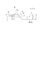
- FIG. 1 is a plan view of a grain-oriented electrical steel sheet 1 according to this embodiment.
- 2 is a cross-sectional view taken along line AA in FIG.
- the rolling direction of the grain-oriented electrical steel sheet 1 is X
- the sheet width direction of the grain-oriented electrical steel sheet 1 (direction perpendicular to the rolling direction in the same plane)
- the thickness direction of the grain-oriented electrical steel sheet 1 is defined as Z.
- the grain-oriented electrical steel sheet 1 according to the present embodiment has grooves 3 for magnetic domain subdivision on the steel sheet surface 2a.
- FIG. 1 is a schematic diagram showing a groove 3 when the grain-oriented electrical steel sheet according to the present embodiment is viewed from the thickness direction Z (hereinafter sometimes referred to as “plan view”).
- the groove 3 when the groove 3 is viewed from the plate thickness direction Z (when the groove 3 is viewed in plan), the extending direction of the groove 3 (arrow L shown in FIG. 1) is referred to as a groove longitudinal direction L.
- the direction (arrow Q shown in FIG. 1) orthogonal to the groove longitudinal direction L of the groove 3 is referred to as a groove width direction Q.
- the surface 2a and the groove 3 of the actual grain-oriented electrical steel sheet are not formed uniformly, but from FIG. 1 to FIG. 3, FIG. 5 to FIG. 8, and FIG. This is schematically shown in FIG.
- the groove 3 may have an arcuate shape when viewed from the plate thickness direction Z (when the groove 3 is viewed in plan).
- channel 3 which has a linear shape is illustrated for convenience of explanation.
- the grain-oriented electrical steel sheet 1 includes a steel sheet (base metal) 2 in which the crystal orientation is controlled so that the easy axis of crystal grains coincides with the rolling direction X by a combination of cold rolling and annealing. 2 has a groove 3 on the surface (steel plate surface 2a).
- Steel plate 2 has chemical fractions of mass fractions of Si: 0.8% to 7%, C: more than 0% to 0.085%, acid-soluble Al: 0% to 0.065%, N: 0% 0.012%, Mn: 0% to 1%, Cr: 0% to 0.3%, Cu: 0% to 0.4%, P: 0% to 0.5%, Sn: 0% to 0% .3%, Sb: 0% to 0.3%, Ni: 0% to 1%, S: 0% to 0.015%, Se: 0% to 0.015%, with the balance being Fe and Consists of impurities.
- the chemical component of the steel plate 2 is a preferable chemical component after accumulating the crystal orientation in the ⁇ 110 ⁇ ⁇ 001> orientation, that is, after controlling the Goss texture.
- Si and C are basic elements
- acid-soluble Al, N, Mn, Cr, Cu, P, Sn, Sb, Ni, S, and Se are selective elements. Since the above-mentioned selective element may be contained according to the purpose, it is not necessary to limit the lower limit value, and the lower limit value may be 0%. Even if these selective elements are contained as impurities, the effect of the present embodiment is not impaired.
- the balance of the basic element and the selective element may be made of Fe and impurities.
- an impurity means the element mixed unavoidable from the ore as a raw material, a scrap, or a manufacturing environment, when manufacturing the steel plate 2 industrially.
- a magnetic steel sheet it is common for a magnetic steel sheet to undergo purification annealing during secondary recrystallization.
- the purification annealing the inhibitor forming elements are discharged out of the system.
- the decrease in the concentration is remarkable, and it becomes 50 ppm or less. Under normal purification annealing conditions, 9 ppm or less, further 6 ppm or less. If the purification annealing is sufficiently performed, it reaches a level that cannot be detected by general analysis (1 ppm or less).
- the chemical composition of the steel plate 2 may be measured by a general steel analysis method.
- the chemical component of the steel plate 2 may be measured using ICP-AES (Inductively Coupled Plasma-Atomic Emission Spectrometry). Specifically, a 35 mm square test piece was collected from the center position of the steel plate 2 after removal of the film, and based on a calibration curve prepared in advance by an ICP emission analyzer (for example, ICPS-8100 manufactured by Shimadzu Corporation). It can be specified by measuring under conditions.
- C and S may be measured using a combustion-infrared absorption method, and N may be measured using an inert gas melting-thermal conductivity method.
- the grain-oriented electrical steel sheet 1 may have an insulating film (not shown) on the groove 3 and the steel sheet surface 2a.
- a glass film (not shown) may be provided between the steel plate surface 2a and the insulating film.
- the glass film is composed of a composite oxide such as forsterite (Mg 2 SiO 4 ), spinel (MgAl 2 O 4 ), and cordierite (Mg 2 Al 4 Si 5 O 16 ).
- the glass coating is a coating formed to prevent seizure from occurring in the steel plate 2 in the finish annealing step, which is one of the manufacturing processes of the grain-oriented electrical steel plate 1. Therefore, the glass film is not an essential element as a component of the grain-oriented electrical steel sheet 1.
- the insulating film contains, for example, colloidal silica and phosphate, and plays a role of giving the steel sheet 2 not only electrical insulation but also tension, corrosion resistance, heat resistance, and the like.
- the glass film and insulating film of the grain-oriented electrical steel sheet 1 can be removed by the following method, for example.
- the grain-oriented electrical steel sheet 1 having a glass film or an insulating film is immersed in an aqueous sodium hydroxide solution of NaOH: 10% by mass + H 2 O: 90% by mass at 80 ° C. for 15 minutes. Then, it is immersed in a sulfuric acid aqueous solution of H 2 SO 4 : 10% by mass + H 2 O: 90% by mass at 80 ° C. for 3 minutes. After that, it is washed by dipping for 1 minute at room temperature with a nitric acid aqueous solution of HNO 3 : 10% by mass + H 2 O: 90% by mass.
- the groove 3 extends in a direction crossing the rolling direction X, and is formed so that the depth direction is a plate thickness direction Z.
- the grain-oriented electrical steel sheet 1 has a groove group 30 composed of a plurality of grooves 3 arranged in the sheet width direction Y when the steel sheet surface 2a is viewed from the sheet thickness direction Z.
- channel 3 which comprises the groove group 30 is distribute
- the plurality of grooves 3 constituting the groove group 30 are the first groove 31 and the second groove 32 in order from the reference end portion 21a.
- a plurality of nth grooves 3n are formed.
- the first groove 31, the second groove 32, and the n-th groove 3 n are arranged so that the ends of the adjacent grooves 3 overlap on the projection plane orthogonal to the rolling direction X. Is done.
- the groove group 30 is preferably arranged so that the other groove group 30 is separated from the rolling direction X.
- the groove 3 is formed with inclined portions 5 that are inclined at both ends in the groove longitudinal direction L such that the depth increases from the steel plate surface 2 a toward the bottom 4 of the groove 3.
- the groove longitudinal direction L if it arrange
- the depth of the groove 3 refers to the length in the plate thickness direction Z from the height of the steel plate surface 2a to the surface of the groove 3 (bottom 4).
- the average groove depth D may be measured as follows.
- the observation range is set to a part of the groove 3.
- the observation range is desirably set in a region excluding an end portion of the groove 3 in the groove longitudinal direction L (that is, a region where the shape of the groove bottom is stable).
- the observation range may be an observation region in which the length in the groove longitudinal direction L is approximately 30 ⁇ m to 300 ⁇ m at a substantially central portion in the groove longitudinal direction L.
- a height distribution (groove depth distribution) within the observation range is obtained using a laser microscope, and the maximum groove depth within this observation range is obtained.
- the same measurement is performed in at least 3 regions, more preferably 10 regions by changing the observation range.
- the average value of the maximum groove depth in each observation area is calculated, and this is defined as the groove average depth D.
- the average groove depth D of the grooves 3 in the present embodiment is preferably, for example, 5 ⁇ m or more and 100 ⁇ m or less, and more preferably more than 10 ⁇ m and 40 ⁇ m or less in order to obtain the effect of magnetic domain refinement.
- the position (height) of the steel plate surface 2a in the plate thickness direction Z needs to be measured in advance.
- the position (height) in the plate thickness direction Z is measured using a laser microscope for each of a plurality of locations on the steel plate surface 2a within each observation range, and the average value of the measurement results is the height of the steel plate surface 2a.
- the steel plate surface 2a may be measured from the groove short cross section.
- two plate surfaces (observation surface and its back surface) of this steel plate sample are substantially parallel.
- the width of the groove 3 refers to the length of the groove opening portion in the groove short direction Q when the groove 3 is viewed in a cross section (groove width direction cross section or groove short cross section) orthogonal to the groove longitudinal direction L.
- the average groove width W may be measured as follows.
- the observation range is set to a part of the groove 3.
- the observation range is desirably set in a region excluding an end portion of the groove 3 in the groove longitudinal direction L (that is, a region where the shape of the groove bottom is stable).
- the observation range may be an observation region in which the length in the groove longitudinal direction L is approximately 30 ⁇ m to 300 ⁇ m at a substantially central portion in the groove longitudinal direction L.
- a groove short section perpendicular to the groove longitudinal direction L is obtained at an arbitrary position within the observation range (for example, the position of the maximum groove depth in the observation region) using a laser microscope.
- the length of the groove opening is determined from the steel sheet surface 2a and the contour curve of the groove 3 appearing in the short cross section of the groove.
- the cross-sectional curve is obtained.
- bandpass filters cut-off values ⁇ f and ⁇ c
- a curve WWC is obtained.
- the waviness curve is a kind of contour curve suitable for simplifying the contour shape itself with a smooth line.
- the depth from the steel plate surface 2 a to the surface of the groove 3 along the plate thickness direction Z on the undulation curve WWC of the groove 3 in the short section of the groove is the average groove depth of the groove 3.
- the same measurement is performed in at least 3 regions, more preferably 10 regions by changing the observation range. Then, the average value of the groove openings in each observation region is calculated, and this is defined as the average groove width W.
- the average groove width W of the grooves 3 in the present embodiment is preferably 10 ⁇ m or more and 250 ⁇ m or less, for example, in order to preferably obtain the effect of magnetic domain subdivision.
- the position (height) of the steel plate surface 2a in the plate thickness direction Z needs to be measured in advance.
- the position (height) in the plate thickness direction Z is measured for each of a plurality of locations on the surface of the steel plate 2a on the undulation curve in each of the short cross sections of each groove, and the average value of the measurement results is calculated as the height of the steel plate surface 2a You may use it.
- the first angle ⁇ of the groove 3 refers to an angle formed by the steel plate surface 2 a and the end of the groove 3.
- the first angle ⁇ may be measured as follows.
- the observation range is set to a part including the end of the groove 3 in the groove longitudinal direction L.
- the groove 3 is viewed in plan from the plate thickness direction Z, and a plurality (n) of virtual lines L 1 to L n are virtually set within the observation range along the groove longitudinal direction L (see FIG. 6).
- the observation range it is desirable to set the observation range to a region including the end of the groove 3 (that is, a region including a region from the beginning of the groove 3 in the groove longitudinal direction L to a region where the shape of the groove bottom is stable).
- a laser microscope laser type surface roughness measuring instrument
- the measurement cross-sectional curve MCL1 that forms the contour in the groove longitudinal direction L at the end of the groove 3 is obtained in a form along the imaginary line L1.
- the band-pass filters (cut-off values ⁇ f and ⁇ c) are applied to the cross-sectional curve.
- the wavy curve LWC1 that forms the contour in the groove longitudinal direction L of the end of the groove 3 is formed along the imaginary line L1. It is obtained by.
- the waviness curve LWC1 is used, and the thickness direction between the steel plate surface 2a and the contour of the groove 3 (that is, the waviness curve LWC1) at each of a plurality (n) of positions along the virtual line L1.
- a distance of Z depth d1 to dn: unit is ⁇ m
- an average value of these depths d1 to dn is obtained.
- the groove depths D2 to Dn of the groove end portions are obtained for each of the other virtual lines L2 to Ln.
- the position (height) of the steel plate surface 2a in the plate thickness direction Z needs to be measured in advance.
- the position (height) in the plate thickness direction Z is measured using a laser microscope for each of a plurality of locations on the steel plate surface 2a within the observation range, and the average value of the measurement results is taken as the height of the steel plate surface 2a. May be used.
- a virtual line that satisfies the condition that the average depth of the groove is maximized along the groove longitudinal direction L is selected as the groove reference line BL.
- the virtual line L2 is defined as the groove reference line BL.
- a straight line connecting the second point 52 having a depth of 0.50 ⁇ D in the thickness direction Z is defined as a groove end straight line 3E.
- channel 3 is defined as the inclination angle with respect to the steel plate surface 2a of the groove end straight line 3E.
- the steel plate surface 2a needs to be linearly approximated.
- the region of only the steel plate surface 2a excluding the groove 3 may be linearly approximated on the waviness curve based on the groove reference line BL. What is necessary is just to measure the inclination angle of the steel plate surface 2a approximated to the straight line and the groove end straight line 3E. By the same method, the inclination angle (first angle ⁇ ) formed by the groove end straight line 3E and the steel plate surface 2a at both ends in the groove longitudinal direction L of the groove 3 is obtained.
- the groove longitudinal projection line LWP may be measured as follows.
- the observation range includes a region including the entire groove 3 or a region including the end of the groove 3 (that is, the groove bottom from the beginning of the groove longitudinal direction L of the groove 3). Region including the region where the shape of the image is stable. Within this observation range, a plurality of imaginary lines along the groove longitudinal direction L are virtually set.
- the virtual lines L 1 to L n can be set to an arbitrary height in the plate thickness direction Z. Then, an imaginary line with the maximum groove depth is selected by the same method as described for the groove reference line BL. A curve obtained when the groove depth distribution along the selected imaginary line is projected on the projection plane as an overall contour (waviness curve) in the groove longitudinal direction L of the groove 3 is defined as a groove longitudinal projection line LWP.
- a region including the entire two adjacent grooves, or a region including the overlapping end portions of the two adjacent grooves that is, a region where the shape of the groove bottom of one groove is stable
- Two groove ends in the groove longitudinal direction L in each groove constituting the groove group 30 are defined as a first groove end and a second groove end in order from the reference end portion 21a.
- the first groove end 31a and the second groove end 31b of the first groove long projection line LWP1 of the first groove 31, the second groove long projection line LWP2 of the first groove 31 and the second groove end 31b of the second groove 32 are shown.
- a groove end 32b is schematically shown.
- two adjacent to the plate width direction Y among the plurality of grooves 3 of the grain-oriented electrical steel sheet 1 according to the present embodiment Only the grooves 31 and 32 are extracted and described.
- the grain-oriented electrical steel sheet 1 includes a second groove end 31 b of the first groove 31 adjacent to the plate width direction Y and a first groove end 32 a of the second groove 32. Further, they are arranged so as to overlap in the plate width direction Y.
- the first groove 31 and the second groove 32 adjacent to each other in the plate width direction Y exemplify an arrangement in which the end portions do not overlap when viewed from the plate thickness direction Z.
- the end portions of the first groove 31 and the second groove 32 may overlap when viewed from the plate thickness direction Z.
- the first groove 31 and the second groove 32 are completely overlapped when viewed in the thickness direction Z, it can be regarded as one groove.
- the position in the plate width direction Y of the first groove end 32a of the second groove 32 in the second groove longitudinal projection line LWP2 is the plate width direction Y of the second groove end 31b of the first groove 31 in the first groove longitudinal projection line LWP1. Adjacent grooves overlap in the plate width direction Y so as to be positioned closer to the reference end portion 21a than the position of. As shown in FIG. 8, the first groove 31 and the second groove 32 are in the plate width direction Y between the second groove end 31 b of the first groove 31 and the first groove end 32 a of the second groove 32. It is the area
- a plurality of grooves are formed in the sheet width direction Y, and the adjacent grooves 31, 32 overlap each other, whereby the grooves 31, 32,. Even if 3n is used, the iron loss can be kept low. That is, in order to improve the rust resistance, even in the groove 3 in which the inclined portions are formed at both ends in the groove longitudinal direction L, the plurality of grooves 3 are arranged in the plate width direction Y and adjacent to each other. By disposing both ends of the groove so as to overlap in the plate width direction Y, the iron loss can be improved as in the case where one groove having a uniform depth is formed in the plate width direction Y.
- the grain-oriented electrical steel sheet 1 according to the present embodiment can further improve the iron loss of the grain-oriented electrical steel sheet when the following conditions are satisfied.
- the separation distance (distance F1 shown in FIG. 1) between the first groove 31 and the second groove 32 adjacent to each other in the sheet width direction Y is the rolling direction X between the groove groups 30 adjacent to each other in the rolling direction X. Is set smaller than the distance (distance F2 shown in FIG. 1).
- the steel sheet surface 2a of the groove longitudinal depth of the thickness direction Z to the contour of the L is 0.05 ⁇ D A position (second groove a point) on the longitudinal projection line LWP2 referred to 0.05 D a position of the first groove end 32a of the second groove 32 (first point).
- the plurality of grooves 3 are arranged in the plate width direction Y and adjacent to each other groove 31.
- the iron loss of the grain-oriented electrical steel sheet 1 can be further improved.
- An arbitrary point on the first groove longitudinal projection line LWP1 included in the overlap region R between the first groove end 32a of the second groove 32 and the second groove end 31b of the first groove 31 is defined as P1, and the overlap is performed.
- a point whose distance from the reference end 21a is equal to the point P1 is P2. .
- the depth in the plate thickness direction Z from the steel plate surface 2a of the first groove 31 to the point P1 on the first groove longitudinal projection line LWP1, and the steel plate surface of the second groove 32 2a from the total depth of the depth of the thickness direction Z of the point P2 on the second groove longitudinal projection line LWP2 is 0.5 ⁇ D a or more. That is, the points P1 and P2 no matter present in the position of the overlap region R in the throat, a condition referred to as "total depth is 0.5 ⁇ D A or" above is satisfied. As shown in FIGS.
- the depth of the first groove 31 and the depth of the second groove 32 at each point P (P1, P2) having the same distance from the reference end 21a. Is added.
- the sum of the depth of the depth and the second grooves 32 of the first groove 31 in the point P is to groove group average depth D A of the depth of the plurality of grooves formed in the plate width direction Y, grooves 3 are arranged such that 0.5 ⁇ D a or more.
- FIG. 8 shows on the coordinates the groove longitudinal projection line obtained by projecting the contour in the groove longitudinal direction L on the projection surface.
- FIG. 9 is a graph showing the relationship between the position in the plate width direction Y of the region from the first end 31a of the first groove 31 to the second groove end 32b of the second groove 32 and the total groove depth.
- the groove longitudinal projection line is shown as a straight line.
- the first groove 31 and the second groove 32 overlap each other from the end of each groove to the region of the bottom 4 described in the above embodiment. Therefore, as shown in FIG.
- a first groove 31 total groove depth of the second groove 32 is at most groove group average depth D A in the plate width direction Y It doubled approximately, the minimum value of the total groove depth is substantially equal to the groove group average depth D a in the plate width direction Y.
- FIGS. 10 and 11 An example in which the width of the overlap region R between the adjacent first groove 31 and the second groove 32 is different from the example illustrated in FIG. 8 is illustrated in FIGS. 10 and 11.
- the regions of the inclined portions 5 of the first groove 31 and the second groove 32 overlap each other. That is, the first groove longitudinal projection line LWP1 and the second groove longitudinal projection line LWP2 overlap so as to intersect at the positions of the inclined portions 5 of the first groove 31 and the second groove 32, respectively.
- the minimum total groove depth of the first groove 31 and the second groove 32 at each point P (P1, P2) having the same distance from the reference end 21a. value is smaller than the groove group average depth D a in the plate width direction Y.
- the total value of the depth of the first groove 31 and second groove 32 is equal to 0.5 ⁇ D A more
- a depth that is not inferior to the depth of the bottom 4 that is a non-overlapping region is ensured.
- the depth of the first groove 31 and the second groove 32 at the point P (P 1, P 2) in the plate width direction Y is greater than the sum of the depth, adjacent to relative average (groove group average depth) D a depth of a plurality of grooves formed in the plate width direction Y, a 0.7 ⁇ D a more grooves in the Is sufficient to obtain the desired groove depth in the sheet width direction Y (the total groove depth of the two grooves 31 and 32 in the overlap region R) in order to improve the iron loss. Can be improved.
- the upper limit of the sum of the depth of the first groove 31 and the depth of the second groove 32 at the point P (P1, P2) on the plate width direction Y is not limited, but considering the decrease in magnetic flux density, the groove may be two times the group mean depth D a. Further, when the sum of the depth of the first depth of the groove 31 and second groove 32 in the P (P1, P2) points on the plate width direction Y, and more than twice the groove group average depth D A, Since the amount of variation in the groove depth in the plate width direction Y can be kept small, the iron loss can be more effectively and stably improved.
- the grain-oriented electrical steel sheet 1 according to the present embodiment is theoretical if both ends of the groove 3 in the groove longitudinal direction L (first groove ends 31a, 32a, second groove ends 31b, 32b) are perpendicular to the steel plate surface 2a. It is considered that sufficient iron loss can be obtained even without the overlap region R. However, it may be difficult to reliably form a groove having an end face perpendicular to the steel plate surface 2a. In addition, when a groove having a depth exceeding 10 ⁇ m with respect to the steel plate surface 2a is formed, a change in the shape of the end of the groove 3 tends to increase, and after the formation of the groove 3, the steel plate surface 2a is provided with electrical insulation.
- the grain-oriented electrical steel sheet 1 improves the rust resistance by stabilizing the shape of the end of the groove 3 by forming an inclined surface at the end of the groove 3 in the groove longitudinal direction L, and In addition, at least the inclined surface of the end portion of the groove 3 is overlapped in the first groove longitudinal projection line LWP1 and the second groove longitudinal projection line LWP2 in the plate width direction Y, thereby maintaining good iron loss and rust resistance. Is preferable.
- the grain-oriented electrical steel sheet 1 according to the present embodiment can realize both improvement in rust resistance and improvement in iron loss when the following conditions are satisfied.
- the groove 3 provided in the grain-oriented electrical steel sheet 1 according to the present embodiment has an angle formed between the groove end straight line 3 ⁇ / b> E and the steel plate surface 2 a at the groove ends 31 a and 31 b in the groove longitudinal direction L of the groove 3 (first The end of the groove 3 is inclined so that the relationship between the angle ⁇ ) and the aspect ratio A obtained by dividing the average groove depth D by the average groove width W satisfies the following formula (1).
- theta which shows the inclination-angle of the inclination part 5
- regulated based on the aspect-ratio A D / W obtained by dividing the groove average depth D by the average groove width W.
- the larger the average groove depth D the more the iron loss affected by the groove depth is improved.
- the smaller the average groove width W the smaller the amount of magnetic flux density deteriorated due to the steel part removal, and the iron loss. Can be improved. That is, the larger the aspect ratio A, the more preferably the magnetic characteristics can be controlled.
- the aspect ratio A is larger, the coating liquid is less likely to enter the groove, so that the rust resistance is deteriorated.
- the groove 3 has the effect of achieving both improved magnetic properties and rust resistance.
- Formula (1) is a suitable range when the groove
- the upper limit of the depth of the groove 3 is not particularly limited.
- the average depth D of the grooves 3 is 30% or more with respect to the thickness in the plate thickness direction Z of the grain-oriented electrical steel sheet, the amount of the grain-oriented electrical steel sheet, that is, the steel sheet, which is a magnetic material, decreases. There is a risk that the density will decrease.
- the upper limit value of the average depth D of the grooves 3 may be 100 ⁇ m.
- channel 3 may be formed only in the single side
- the first angle ⁇ of the groove end of the groove 3 satisfies the following formula (3) with respect to the groove average depth D and the average groove width W. And it is more preferable at the point which improves rust resistance.
- the first angle ⁇ of the groove end of the groove 3 satisfies the following formula (4) with respect to the groove average depth D and the average groove width W: It is more preferable in terms of improving rust resistance.
- the glass film Alternatively, the insulating film can be coated evenly, and both magnetic properties and rust resistance can be achieved.
- the average groove width W is more than 30 ⁇ m and not more than 100 ⁇ m, both the magnetic characteristics and the rust resistance can be achieved if the first angle ⁇ satisfies the above formula (4).
- a glass film having an average thickness of 0 to 5 ⁇ m and an insulating film having an average thickness of 1 ⁇ m to 5 ⁇ m may be disposed. Further, a glass film having an average thickness of 0.5 ⁇ m to 5 ⁇ m and an insulating film having an average thickness of 1 ⁇ m to 5 ⁇ m may be disposed on the steel plate surface 2a. Furthermore, the average thickness of the glass film in the groove 3 may be thinner than the average thickness of the glass film on the steel plate surface 2a.
- the distance (groove width) between the walls of the opposing grooves is made narrower by adopting a configuration in which the glass coating does not exist in the grooves 3 (that is, a configuration in which the average thickness of the glass coating in the grooves 3 is 0). Therefore, the magnetic domain refinement effect (that is, the effect of reducing abnormal eddy current loss) by the grooves 3 can be further improved.
- the glass film is not an essential component. Therefore, the effect of improving rust resistance can be obtained by applying the above embodiment also to the grain-oriented electrical steel sheet composed only of the steel sheet 2 and the insulating film.
- an insulating coating having an average thickness of 1 ⁇ m or more and 5 ⁇ m or less is formed in the groove 3, and an insulation having an average thickness of 1 ⁇ m or more and 5 ⁇ m or less on the steel plate surface 2 a.
- a film may be formed.
- the average grain size of the crystal grains (secondary recrystallized grains) in contact with the grooves 3 is 5 ⁇ m or more.
- the upper limit of the grain size of the crystal grains in contact with the groove 3 is not particularly limited, but the upper limit may be 100 ⁇ 10 3 ⁇ m or less.
- the average grain size of the crystal grains (secondary recrystallized grains) in contact with the groove 3 is 5 ⁇ m or more.
- the upper limit of the grain size of the crystal grains in contact with the groove 3 is not particularly limited, but the upper limit may be 100 ⁇ 10 3 ⁇ m or less.
- the grain size of the crystal grain means an equivalent circle diameter.
- the crystal grain size may be obtained by a general crystal grain size measurement method such as ASTM E112, or may be obtained by an EBSD (Electron Back Scattering Pattern Pattern) method. Further, the crystal grains in contact with the groove 3 may be observed in the above-mentioned groove short section or a section perpendicular to the plate thickness direction Z.
- the groove not having the melt resolidification region can be obtained by, for example, a manufacturing method described later.
- the grain size direction grain size of the crystal grains (secondary recrystallized grains) present in the lower part of the groove 3 in the steel sheet 2 is 5 ⁇ m or more and the thickness of the steel sheet 2 or less It is preferable that This feature means that there is no fine grain layer (melt resolidification region) having a grain thickness direction grain size of about 1 ⁇ m below the groove 3 in the steel plate 2.
- FIG. 12 is a flowchart showing a manufacturing process of the grain-oriented electrical steel sheet 1.
- Si 0.8% to 7%
- C more than 0% to 0.085%
- acid-soluble Al 0% to 0.065 %
- N 0% to 0.012%
- Mn 0% to 1%
- Cr 0% to 0.3%
- Cu 0% to 0.4%
- P 0% to 0.5%
- Sn 0% to 0.3%
- Sb 0% to 0.3%
- Se 0% to 0.015%
- the molten steel which has a chemical component which the remainder consists of Fe and an impurity is supplied to a continuous casting machine, and a slab is produced continuously.
- the slab obtained from the casting step S01 is heated at a predetermined temperature condition (for example, 1150 to 1400 ° C.), and then the hot rolling is performed on the slab.
- a predetermined temperature condition for example, 1150 to 1400 ° C.
- the hot-rolled steel sheet obtained from the hot rolling step S02 is annealed under a predetermined temperature condition (for example, a condition of heating at 750 to 1200 ° C. for 30 seconds to 10 minutes). Is implemented.
- a predetermined temperature condition for example, a condition of heating at 750 to 1200 ° C. for 30 seconds to 10 minutes.
- the surface of the hot rolled steel sheet subjected to the annealing process in the annealing step S03 is subjected to pickling treatment as necessary, and then cold rolling is performed on the hot rolled steel sheet.
- pickling treatment as necessary, and then cold rolling is performed on the hot rolled steel sheet.
- a cold-rolled steel sheet having a thickness of 0.15 to 0.35 mm is obtained.
- the cold-rolled steel sheet obtained from the cold rolling step S04 has a predetermined temperature condition (for example, a condition of heating at 700 to 900 ° C. for 1 to 3 minutes) and a humid atmosphere.
- Heat treatment that is, decarburization annealing
- a decarburization annealing process is implemented, in a cold-rolled steel plate, carbon will be reduced to a predetermined amount or less, and a primary recrystallized structure will be formed.
- an oxide layer containing silica (SiO 2 ) as a main component is formed on the surface of the cold rolled steel sheet.
- an annealing separator containing magnesia (MgO) as a main component is applied to the surface of the cold rolled steel sheet (the surface of the oxide layer).
- the finish annealing step S07 the cold-rolled steel sheet coated with the annealing separator is subjected to heat treatment under a predetermined temperature condition (for example, a condition of heating at 1100 to 1300 ° C. for 20 to 24 hours) (ie, Finish annealing) is performed.
- a predetermined temperature condition for example, a condition of heating at 1100 to 1300 ° C. for 20 to 24 hours
- the oxide layer containing silica as a main component reacts with an annealing separator containing magnesia as a main component, so that forsterite ( A glass film (not shown) containing a complex oxide such as Mg 2 SiO 4 ) is formed.
- the finish annealing process is performed in a state where the steel plate 2 is wound in a coil shape.
- an insulating coating liquid containing, for example, colloidal silica and phosphate is applied to the steel plate surface 2a from above the glass film. Thereafter, heat treatment is performed under a predetermined temperature condition (for example, 840 to 920 ° C.), whereby an insulating film is formed on the surface of the glass film.
- a predetermined temperature condition for example, 840 to 920 ° C.
- the groove 3 is formed on the steel plate surface 2a on which the glass film and the insulating film are formed.
- the grain-oriented electrical steel sheet 1 according to the present embodiment can form grooves by a method such as a laser method, a press machine method, an etching method, or the like.
- a method for forming the groove 3 when using a laser method, a press machine method, an etching method, or the like in the groove forming step S09 will be described.
- the laser light YL emitted from the laser light source (not shown) is transmitted to the laser irradiation device 10 via the optical fiber 9.
- the laser irradiation device 10 incorporates a polygon mirror and its rotation drive device (both not shown).
- the laser irradiation device 10 irradiates the laser beam YL toward the surface of the steel plate 2 by rotating the polygon mirror and scans the laser beam YL substantially parallel to the plate width direction Y of the steel plate 2.
- an assist gas 25 such as air or an inert gas is blown onto the portion of the steel plate 2 to which the laser beam YL is irradiated.
- the inert gas is, for example, nitrogen or argon.
- the assist gas 25 has a role of removing a component melted or evaporated from the steel plate 2 by laser irradiation. Since the laser beam YL stably reaches the steel plate 2 by spraying the assist gas 25, the groove 3 is stably formed. Moreover, it can suppress that the said component adheres to the steel plate 2 by spraying of the assist gas 25. FIG. As a result, the groove 3 is formed along the scanning line of the laser beam YL.
- the surface of the steel plate 2 is irradiated with the laser beam YL.
- the rotational speed of the polygon mirror is synchronously controlled with respect to the conveying speed of the steel plate 2 so that the grooves 3 are formed at a predetermined interval PL along the rolling direction X.
- a plurality of grooves 3 intersecting the rolling direction X are formed on the surface of the steel plate 2 at a predetermined interval PL along the rolling direction X.
- a fiber laser for example, a fiber laser can be used.
- a high-power laser generally used for industrial use such as a YAG laser, a semiconductor laser, or a CO 2 laser, may be used as the laser light source.
- a pulse laser or a continuous wave laser may be used as the laser light source.
- the laser output is 200 W to 2000 W
- the focused spot diameter in the rolling direction X of the laser beam YL (that is, the diameter including 86% of the laser output, hereinafter abbreviated as 86%) Is 10 ⁇ m to 1000 ⁇ m
- the focused spot diameter (86% diameter) of the laser beam YL in the plate width direction Y is 10 ⁇ m to 4000 ⁇ m
- the laser scanning speed is 1 m / s to 100 m / s
- the laser scanning pitch (interval PL) Is preferably set to 4 mm to 10 mm.
- the laser scanning direction SD ( The assist gas 25 is injected so as to follow the laser beam YL from a direction having an inclination of an angle ⁇ 2 with respect to the plate width direction Y).
- the direction has an inclination of an angle ⁇ 3 with respect to the steel plate surface 2a. Then, the assist gas 25 is injected so as to follow the laser beam YL.
- the angle ⁇ 2 is preferably set in the range of 90 ° to 180 °, and the angle ⁇ 3 is preferably set in the range of 1 ° to 85 °.
- the flow rate of the assist gas 25 is preferably set in the range of 10 to 1000 liters per minute. Furthermore, it is preferable to control the atmosphere so that the number of particles having a diameter of 0.5 ⁇ m or more present in the through-plate atmosphere of the steel plate 2 is 10 or more and less than 10,000 per 1 CF (cubic feet).
- Scanning of the laser beam over the entire width of the grain-oriented electrical steel sheet may be performed by one scanning device as shown in FIG. 13, or may be performed by a plurality of scanning devices as shown in FIG.
- the laser beam emitted from this light source may be divided into laser beams.
- the plurality of laser irradiation apparatuses 10 are arranged at predetermined intervals along the rolling direction X as shown in FIG. Further, the position of each laser irradiation device 10 in the plate width direction Y is set so that the laser scanning lines of each laser irradiation device 10 do not overlap each other when viewed from the rolling direction X.
- a plurality of grooves 3 can be formed on the steel plate surface 2a.
- the irradiation region can be divided into a plurality of portions in the plate width direction Y, so that the scanning and irradiation time required for each laser beam is shortened. Therefore, it is particularly suitable for high-speed threading equipment.
- a plurality of scanning devices are used, only one laser device that is a light source of a laser beam incident on each scanning device may be provided, or one laser device may be provided for each scanning device. .
- the laser beam is scanned on the directional electromagnetic steel sheet by one surface of the mirror, and a groove having a predetermined length (for example, 300 mm) is formed in the substantially width direction on the directional electromagnetic steel sheet.
- the interval between grooves adjacent to the rolling direction X that is, the irradiation pitch PL in the rolling direction X (conveying direction) can be changed by adjusting the line speed VL and the irradiation speed.
- a directional electromagnetic steel sheet is irradiated with a laser beam to form grooves in the rolling direction X at a constant scanning interval PL (irradiation pitch, groove interval).
- the laser beam is focused on the surface of the grain-oriented electrical steel sheet while being scanned, and a direction substantially perpendicular to the transport direction of the grain-oriented electrical steel sheet (a direction intersecting the transport direction, a vector perpendicular to the transport direction).
- a groove having a predetermined length extending in the direction of inclusion) is formed at a predetermined interval in the transport direction.
- the groove 3 is formed, for example, within a range of plus 45 ° to minus 45 ° with respect to a direction substantially perpendicular to the direction of conveyance of the grain-oriented electrical steel sheet.
- the depth of the groove 3 is changed by changing the laser output with time in synchronization with the operation of the mirror, and the end portions 31a and 31b of the groove 3 are inclined. That is, as shown in FIG. 17, it sets so that the output of a laser may change in the position used as the edge part of the groove
- the groove width of the groove 3 is 100 ⁇ m
- the groove depth is 20 ⁇ m
- the irradiation pitch is 3 mm
- the scanning speed on the steel plate is 30 m / s
- the time ⁇ T for changing the laser output at the start and end of formation of one groove is set to 0.0004 ms or more.
- the laser beam is emitted from a laser device as a light source by a scanning device in a plate width direction Y substantially perpendicular to the rolling direction X of the grain-oriented electrical steel sheet. This is performed by scanning at the interval PL.
- an assist gas such as air or an inert gas is sprayed onto a portion of the grain-oriented electrical steel sheet that is irradiated with the laser beam.
- a groove is formed in the portion irradiated with the laser beam on the surface of the grain-oriented electrical steel sheet.
- the rolling direction X coincides with the sheet passing direction.
- the temperature of the grain-oriented electrical steel sheet when performing laser beam irradiation is not particularly limited.
- laser beam irradiation can be performed on a grain-oriented electrical steel sheet having a room temperature.
- the direction in which the laser beam is scanned need not coincide with the plate width direction Y.
- the angle formed by the scanning direction and the sheet width direction Y is in the range of 0 ° to 90 °, and within 45 °, from the viewpoint of work efficiency and the like, and from the point of subdividing the magnetic domains into strips that are long in the rolling direction X. It is preferable.
- the angle formed by the scanning direction and the plate width direction Y is more preferably within 20 °, and still more preferably within 10 °.
- etching resist layer having openings corresponding to the groove shape is formed on the surface of the grain-oriented electrical steel sheet 1 after the insulating film forming step S08 by printing or the like.
- the opening of the etching resist layer is inclined so that the opening width in the lateral direction is gradually reduced so that the opening width at both ends is narrower than the central portion in the groove longitudinal direction L at the position corresponding to the groove end.
- An etching resist is formed.
- the opening of the etching resist has an opening width in the groove short direction Q. Is set to 100 ⁇ m or more, and the length in the groove longitudinal direction L of the portion inclined corresponding to the groove end is 14 ⁇ m.
- the inclined portion 5 is formed at the groove end portion where the opening width of the etching resist is set narrow.
- an etching process NaCl or the like is performed at a liquid temperature of 30 ° C. for 20 seconds.
- channel 3 is formed in the steel plate surface 2a by peeling an etching resist from a grain-oriented electrical steel plate.
- the same processing as the insulating film forming step is performed again (re-insulating film forming step S10).
- the thickness of the insulating film obtained is 2 to 3 ⁇ m.
- the grain-oriented electrical steel sheet according to the present embodiment is obtained.
- the steel sheet 2 of the grain-oriented electrical steel sheet 1 manufactured as described above has, as chemical components, mass ratios of Si: 0.8% to 7%, C: more than 0% to 0.085%, acid-soluble Al. : 0% to 0.065%, N: 0% to 0.012%, Mn: 0% to 1%, Cr: 0% to 0.3%, Cu: 0% to 0.4%, P: 0 % To 0.5%, Sn: 0% to 0.3%, Sb: 0% to 0.3%, Ni: 0% to 1%, S: 0% to 0.015%, Se: 0% to 0.015%, with the balance being Fe and impurities.
- the case where the manufacturing process of forming the groove 3 on the steel plate surface 2a by laser irradiation after the insulating film is formed on the steel plate surface 2a is exemplified.
- the groove 3 immediately after laser irradiation is exposed to the outside, it is necessary to form an insulating film on the steel plate 2 again after the formation of the groove 3.
- the groove 3 is formed on the steel plate surface 2a by irradiating the laser beam YL toward the steel plate surface 2a, and then the insulating coating is formed.
- the grain-oriented electrical steel sheet according to the present embodiment includes the grain-oriented electrical steel sheet 1 in which the high-temperature annealing for secondary recrystallization is completed and the coating of the glass film and the insulating film is completed.
- a grain-oriented electrical steel sheet before completion of the coating of the glass film and the insulating film is also included. That is, you may obtain a final product by forming a glass film and an insulating film as a post process using the grain-oriented electrical steel sheet concerning this embodiment.
- the shape and roughness of the groove 3 after removing the glass film or the insulating film is the same as that before forming the glass film or the insulating film. Has been confirmed.
- the grooving step (laser irradiation step) S09 is performed after the finish annealing step S07 is illustrated, but the grooving step is performed between the cold rolling step S04 and the decarburizing annealing step S05.
- the groove longitudinal direction L which is the extending direction of the groove 3
- the extending direction of the groove 3 of the grain-oriented electrical steel sheet 1 according to the present embodiment is not limited to this.
- the groove longitudinal direction L of the groove 3 is substantially perpendicular to the rolling direction X, both improvement in magnetic properties and rust resistance can be achieved.
- the groove shape having the above-described characteristics can improve the rust resistance in the groove 3 having a depth of 15 ⁇ m or more on the steel plate surface 2a. Therefore, the number of grooves 3 formed in the grain-oriented electrical steel sheet 1 is not particularly limited. For example, a plurality of grooves 3 may be formed in the sheet width direction Y and the rolling direction X.
- the shape of the groove 3 (the shape of the boundary portion between the groove 3 and the steel plate surface 2a) when viewed in plan is an ellipse is illustrated.
- the shape of the groove 3 of the grain-oriented electrical steel sheet 1 is not limited to this.
- the groove 3 may have any shape as long as it has an inclined portion at the end in the groove longitudinal direction L and satisfies the relationship of the above formula (1).
- FIG. 3 shows an example in which the shape of the groove 3 as viewed from the short-side direction Q of the groove is asymmetrical with respect to the center of the groove width in the short-side direction Q.
- the shape of the groove 3 is not limited to this.
- the grain-oriented electrical steel sheet 1 according to the present embodiment is more effective when the groove average depth D is 10 ⁇ m or more and 50 ⁇ m or less.
- the example in which the groove longitudinal direction L, which is the extending direction of the groove 3, is a direction intersecting the rolling direction X and the sheet width direction Y is shown, but is not limited thereto, and the groove 3 is rolled. What is necessary is just the structure extended in the direction which cross
- the grain-oriented electrical steel sheet 1 according to the present embodiment has the inclined surfaces 31, 32,..., 3 n by providing the overlap region between the plurality of grooves in the plate width direction Y as described above. Even if is used, the iron loss can be kept low. That is, as in the grain-oriented electrical steel sheet 1 of the present embodiment, even if the groove 3 is formed with inclined surfaces at both ends in the groove longitudinal direction L in order to improve the rust resistance, the plurality of grooves 3 have a plate width. Even if the end portions of the respective grooves 31, 32,..., 3n are shallow by arranging both ends of the adjacent grooves 3 in the direction Y and overlapping each other in the plate width direction Y, a uniform depth is obtained. The iron loss can be improved similarly to the case where one groove 3 is formed in the plate width direction Y.
- the grain-oriented electrical steel sheet 1 which concerns on this embodiment is shown.
- the grain-oriented electrical steel sheet 1 according to the present embodiment can be defined as follows from another viewpoint. As shown in FIG. 19, the average value of the depth from the steel plate surface 2a of the first groove longitudinal projection line LWP1, which is the contour of the first groove 31 projected onto the projection plane, in the thickness direction Z is expressed in units of ⁇ m.
- the first groove average depth D I is assumed.
- the average value of the second groove average depth D II in units of ⁇ m is the average value of the depth from the steel plate surface 2a of the second groove longitudinal projection line LWP2, which is the contour of the second groove 32 projected onto the projection plane, to the plate thickness direction Z.
- the overlap region R of the grain-oriented electrical steel sheet 1 according to this modification has a depth from the steel sheet surface 2a at the first groove end 32a of the second groove longitudinal projection line LWP2 toward the sheet thickness direction Z on the projection plane.
- each groove 3 in the grain-oriented electrical steel sheet 1, by forming each groove 3 so that the plurality of grooves 3 overlap each other in the plate width direction Y, even if each groove 3 has the inclined portion 5, the iron loss is reduced. Can be suppressed. That is, even in the groove 3 in which the inclined portions 5 are formed at both ends in the groove longitudinal direction L in order to improve the rust resistance, the plurality of grooves 3 are arranged in the plate width direction Y and are adjacent to each other. By overlapping both end portions in the plate width direction Y, the iron loss can be improved as in the case where one groove 3 having a uniform depth is formed in the plate width direction Y.
- the grain-oriented electrical steel sheet 1 according to this modification can improve the iron loss more preferably when the following conditions are satisfied. Specifically, on the projection plane, the distance La between the third point on the second groove longitudinal projection line LWP2 and the reference end 21a is equal to the fourth groove on the first groove longitudinal projection line LWP1. Is shorter than the distance Lb between this point and the reference end 21a. As a result, since both end portions of the adjacent grooves 3 can be reliably overlapped in the plate width direction Y, the iron loss can be preferably improved.
- the grain-oriented electrical steel sheet 1 according to this modification can more preferably improve the iron loss when the following conditions are satisfied.
- a reference line that is parallel to the plate thickness direction Z in the overlap region R is set on the projection plane, and the first groove longitudinal projection line LWP1 is set on any reference line in the overlap region R.
- the total depth of the depth from the steel plate surface 2a toward the plate thickness direction Z and the depth of the second groove longitudinal projection line LWP2 from the steel plate surface 2a to the plate thickness direction Z is 0.25 ⁇ (D I + DII ) or more.
- the iron loss can be preferably improved.
- the total depth is preferably 0.35 ⁇ (D I + D II ) or more, and the total depth is more preferably 0.45 ⁇ (D I + D II ) or more.
- the distance Lc between the fifth point on the first groove longitudinal projection line LWP1 and the reference end is the distance between the sixth point on the second groove longitudinal projection line LWP2 and the reference end 21a. It may be shorter than Ld.
- the steel part removed by formation of the groove 3 can be reduced, the deterioration amount of the magnetic flux density can be suppressed to be small and the iron loss can be improved. Further, the same effect can be obtained even if the grooves overlap so that the distance Lc of the first groove longitudinal projection line LWP1 is shorter than the distance La of the second groove longitudinal projection line LWP2.
- 19 to 21 show examples in which the width of the overlap region R between the first groove 31 and the second groove 32 is different.
- the first groove 31 and the second groove 32 include the inclined portion 5 and a part of the bottom portion 4 a of the first groove 31 and the bottom portion 4 b of the second groove 32.
- An example of overlapping with a part of is shown.
- channel 32 show the example in which most each inclination part 5 mutually overlaps. That is, in the example shown in FIG. 20, the first groove longitudinal projection line LWP ⁇ b> 1 and the second groove longitudinal projection line LWP ⁇ b> 2 overlap each other at the inclined portions 5.
- FIG. 21 similarly to FIG.
- FIG. 22 shows a profile of the total depth of the first groove longitudinal projection line LWP1 and the second groove longitudinal projection line LWP2 shown in FIG. As shown in FIG. 22, in the overlap region R of the example shown in FIG. 21, the total groove depth of the first groove 31 and the second groove 32 at each point P where the distance from the reference end 21a is equal.
- the upper limit value of the total groove depth of the first groove 31 and the second groove 32 is not particularly limited, as described above, the maximum value is D I + D II .
- the conditions in the examples are one example of conditions adopted for confirming the feasibility and effects of the present invention.
- the invention is not limited to this one condition example.
- the present invention can adopt various conditions as long as the object of the present invention is achieved without departing from the gist of the present invention.
- the hot-rolled material was heat-treated at a temperature of 1000 ° C. for 1 minute (annealing step S03).
- the steel sheet was pickled after the heat treatment and then cold-rolled (cold rolling step S04) to produce a cold-rolled material having a thickness of 0.23 mm.
- the cold-rolled material was subjected to decarburization annealing at a temperature of 800 ° C. for 2 minutes (decarburization annealing step S05).
- An annealing separator containing magnesia as a main component was applied to both surfaces of the cold-rolled material after decarburization annealing (annealing separator application step S06).
- a cold rolled material coated with an annealing separator is charged into a furnace in a coiled state, subjected to a final finishing annealing step S07 at a temperature of 1200 ° C. for 20 hours, and a glass film is formed on the surface. Iron was produced.
- an insulating material mainly composed of aluminum phosphate was applied onto the glass film, and baked at a temperature of 850 ° C. for 1 minute to form an insulating film (insulating film forming step S08).
- the laser scanning pitch (interval PL) is set to 3 mm
- the beam diameter is set to 0.1 mm in the rolling direction X, 0.3 mm in the scanning direction
- the scanning speed is set to 30 m / s.
- a plurality of grooves 31, 32,..., 3 n having an average depth D of 20 ⁇ m, an average groove width W of 100 ⁇ m, an aspect ratio of 0.2, and a first angle ⁇ of 60 ° in the plate width direction Y of the steel plate surface 2 a. Formed (groove processing step S09). After the grooving step S09, an insulating material mainly composed of aluminum phosphate is applied again, and baked at a temperature of 850 ° C. for 1 minute to form an insulating film (re-insulating film forming step S10).
- re-insulating film forming step S10 After the grooving step S09, an insulating material mainly composed of aluminum phosphate is applied again, and baked at a temperature of 850 ° C. for 1 minute to form an insulating film.
- the steel plate (steel plate with grooves formed) in the grain-oriented electrical steel plate finally obtained contained Si: 3.0% mainly.
- Each of the grooves 31, 32,..., 3 n has an inclination angle ⁇ 4 with respect to the plate width direction Y of 15 °, a line connecting the groove end 31 a and the groove end 31 b of the groove 31, and the groove end of the groove 32 positioned next to the groove 31.
- the distance G between the lines connecting the line 32a and the groove end 32b is 1 mm, and is overlapped by 3 mm.
- the second groove end 32b of the first groove 31 and the first groove end 32a of the second groove 32 are The length of a line segment m connecting the second groove end 32b of one groove 31 and the first groove end 32a of the second groove 32 is about 3.4 mm, and the angle ⁇ 5 of the line segment m with respect to the plate width direction Y is about 150.
- a plurality of them were arranged so as to be ° (see FIG. 18).
- the first groove end 32a of the second groove 32 is closer to the reference end 21a side than the second groove end 31b of the first groove 31.
- a groove group average depth D A is 20 [mu] m of Example 1
- the minimum value of the total groove depth in the overlap region R is 20 [mu] m
- a plurality of grooves arranged in the sheet width direction Y were continuously formed in the rolling direction X with a pitch of 3 mm.
- Example 2 to Example 4 having different minimum values of the total groove depth from Example 1 were prepared. That is, in Example 2, the minimum value of the total groove depth in the overlap region R is 10 ⁇ m, in Example 3, the minimum value is 15 ⁇ m, and in Example 4, the minimum value is 25 ⁇ m. .
- Comparative Example 1 a grain oriented electrical steel sheet was prepared in which grooves having the same shape as the grain oriented electrical steel sheet 100 of Example 1 were arranged so that there was no overlap region R. That is, a plurality of grooves having an average groove depth D of 20 ⁇ m, an average groove width W of 100 ⁇ m, an aspect ratio of 0.2, and a first angle ⁇ of 60 ° are arranged in the plate width direction Y. In the groove longitudinal projection line on the projection surface of the electromagnetic steel sheet, the overlap region R was arranged so as not to be formed.
- the second groove end 31b of the first groove 31 is located closer to the reference end portion 21a than the first groove end 32a of the second groove 32, and the first groove end 32a of the second groove 32 is
- the inclination angle of the line segment connecting the second groove end 31b of the first groove 31 was set to be perpendicular to the groove longitudinal direction L and 75 ° to the plate width direction Y. That is, the minimum value of the total groove depth is 0 ⁇ m.
- Comparative Example 2 In Comparative Example 2, but are arranged by overlapping the same manner grooves as in Example 1, the minimum value of the total groove depth in the overlap region R is oriented electrical steel sheet of less than 0.5 ⁇ D A Prepared. That is, Comparative Example 2, the average groove group depth D A is 20 [mu] m, the minimum value of the total groove depth in the overlap region R was prepared oriented electrical steel sheet is 5 [mu] m.
- the contours of the grooves of Example 1 and Comparative Examples 1 and 2 were identified.
- the groove average depth D was calculated from the contours of the ten groove longitudinal sections, and the contour of the groove longitudinal section where the groove average depth D was the deepest was extracted as a representative pattern.
- the groove average depth D of the representative pattern is shown as the groove depth D in Table 1.
- the groove group average depth D A and the total groove depth of each point in the overlap region R were measured.
- the groove group average depth D A of Example 1 is 20 [mu] m
- the minimum value of the total groove depth in the overlap region R is 20 [mu] m
- the minimum value of the total groove depth of the overlap region R and the reached iron loss.
- the overlap region R is formed so that the minimum value of the total depth is 10 ⁇ m or more, the reached iron loss is reached. It became clear that it could be 0.75 W / kg or less.
- the adjacent grooves 3 constituting the groove group 30 overlap each other, and the total If the minimum value of the depth is 0.5 ⁇ D a above, the first angle ⁇ is 30 ° of the groove 3, 45 °, in the case of 60 °, the iron loss were not almost changed.
- the iron loss of the grain oriented electrical steel sheet of Example 1 was superior to the grain oriented electrical steel sheet of Comparative Example 1.
- the iron loss improvements of Examples 1 to 4 and Comparative Examples 1 and 2 were compared.
- the comparison results are shown in Table 1.
- the evaluation of iron loss improvement was performed by measuring the iron loss of the steel plates before the grooving of Examples 1 to 4 and Comparative Examples 1 and 2 (steel plates after the insulating film forming step S08), and using this as the reference iron loss.
- the improvement rate of the iron loss relative to the standard iron loss was obtained.
- the iron loss improvement rate was good in Example 2 and Example 3.
- the iron loss improvement rate was as high as 20%.
- Comparative Example 1 and Comparative Example 2 had a lower iron loss improvement rate than the grain-oriented electrical steel sheets of Examples 1 to 4.
- the laser scanning pitch (interval PL) is set to 3 mm
- the beam diameter is set to 0.1 mm in the rolling direction X, 0.3 mm in the scanning direction
- the scanning speed is set to 30 m / s
- the average groove depth is set.
- a grain-oriented electrical steel sheet having D, an average groove width W in the groove longitudinal direction L, and a groove whose first angle ⁇ is shown in Table 1 below on the steel sheet surface 2a was prepared.
- a grain-oriented electrical steel sheet in which grooves having the average groove depth D, the average groove width W in the groove longitudinal direction L, and the first angle ⁇ shown in Table 2 below were prepared.
- the two-dimensional height distribution of the groove in 20 straight lines in the lateral direction Q of the groove was measured using the same non-contact laser distance meter. Based on the measurement results, 20 patterns of the groove cross-sectional profile of the groove were obtained. In the profile of the obtained 20 short-groove cross sections, the depth from the steel plate surface 2a to the groove surface (on the contour) was measured, and the short-groove average depth Ds was calculated. In the cross-sectional shape of the short groove, two points with a short groove average depth Ds ⁇ 0.05 were extracted, and the distance of the two-point tube was measured as the groove width W. The average value of the groove widths W obtained for each of the 20 patterns was calculated as the average groove width. Table 2 shows the average groove width (unit: ⁇ m) of the grain-oriented electrical steel sheets obtained in Examples 5 to 18 and Comparative Examples 3 to 5, respectively.
- Examples 5 and 6 are examples that satisfy only the relationship of Expression (1) and Expression (2) described in the above embodiment.
- Examples 12 to 18 are examples that satisfy only the relationship of the formula (1) described in the above embodiment.
- Examples 8 and 9 are examples that satisfy the relationship of the expressions (1) to (4) described in the above embodiment.
- Example 7 is an example that satisfies the relationship of the expressions (1), (2), and (4) described in the above embodiment.
- Example 10 is an example that satisfies the relationship of the expressions (1), (2), and (3) described in the above embodiment.
- Comparative Examples 3 to 5 grain-oriented electrical steel sheets that do not satisfy the above formula (1) were prepared.
- the evaluation of rust resistance was obtained by taking a 30 mm square test piece including one groove from each of the grain-oriented electrical steel sheets of the above examples and comparative examples, and setting the test piece to a temperature of 50 ° C. and a humidity of 95% or more. After leaving in a maintained room for 48 hours, the state of occurrence of rust in each test piece was confirmed. The presence or absence of rust was confirmed visually. In addition, the rust resistance was evaluated based on the change in the weight of the test piece before and after the test piece was left in an atmosphere at a temperature of 50 ° C. and a humidity of 91% for one week. Since the weight of the test piece increases when rust occurs, the smaller the weight increase, the better the rust resistance.
- the rust resistance of a test piece having a weight increase of 1.0 mg / m 2 or less is evaluated as “excellent”, and the rust resistance of a test piece having a weight increase of 5.0 mg / m 2 or less is evaluated.
- the test piece having a weight increase of more than 10.0 mg / m 2 was evaluated as “bad”.
- Table 1 as a result of verifying the rust resistance of the grain-oriented electrical steel sheets of Examples 5 to 18, the rust resistance of the grain-oriented electrical steel sheets is improved by forming a groove satisfying at least the formula (1). It was confirmed to improve. In Comparative Examples 3 to 5, the evaluation of rust resistance was poor.
- the grain size of the crystal grains in contact with the grooves in the steel sheet was 5 ⁇ m or more.
Abstract
Description
本願は、2015年4月20日に日本に出願された特願2015-086302号に基づき優先権を主張し、その内容をここに援用する。 The present invention relates to a grain-oriented electrical steel sheet.
This application claims priority based on Japanese Patent Application No. 2015-086302 for which it applied to Japan on April 20, 2015, and uses the content here.
(1)本発明の第1の態様に係る方向性電磁鋼板は、圧延方向と交差する方向に延在しかつ溝深さ方向が板厚方向となる溝が形成された鋼板表面を有する鋼板を備える方向性電磁鋼板において、前記板厚方向から前記鋼板表面を見た場合に、板幅方向に対して前記溝が複数配されて構成される溝群を有し、前記溝群を構成する前記溝が、前記圧延方向と直交する投影面上で隣り合う溝と重なるように配され、前記溝群が前記圧延方向に対して間隔を有して複数配される。
この方向性電磁鋼板において、前記鋼板の前記板幅方向の端部を基準端部とし、前記溝群の複数の前記溝のうちの隣り合う溝を前記基準端部から近い順に第一の溝、第二の溝とし、前記溝群を構成する各溝での前記溝長手方向の2つの溝端を、前記基準端部から近い順に第一溝端、第二溝端とし、前記投影面に投影された前記第一の溝の輪郭を第一溝長手投影線とし、前記投影面に投影された前記第二の溝の輪郭を第二溝長手投影線とし、前記溝群を構成する複数の前記溝の輪郭における平均深さを単位μmで溝群平均深さDAとし、前記第二溝長手投影線の前記第一溝端において前記鋼板表面から前記板厚方向への深さが0.05×DAとなる前記第二溝長手投影線上の点を第1の点とし、前記第一溝長手投影線の前記第二溝端において前記鋼板表面から前記板厚方向への深さが0.05×DAとなる前記第一溝長手投影線上の点を第2の点としたとき、前記投影面において、前記第二溝長手投影線上の前記第1の点と前記基準端部との間の距離が、前記第一溝長手投影線上の前記第2の点と前記基準端部との間の距離より短く、前記第二の溝の前記第一溝端と前記第一の溝の前記第二溝端との間のオーバーラップ領域において、前記第一の溝の前記第二溝端における前記鋼板表面からの前記板厚方向の深さと、前記第二の溝の前記第一溝端における前記鋼板表面からの前記板厚方向の深さとの合計深さが0.5×DA以上である。 The present invention employs the following means in order to solve the above problems and achieve the object.
(1) The grain-oriented electrical steel sheet according to the first aspect of the present invention is a steel sheet having a steel sheet surface formed with a groove extending in a direction intersecting with the rolling direction and having a groove depth direction in the plate thickness direction. In the grain-oriented electrical steel sheet provided, when the steel sheet surface is viewed from the plate thickness direction, the groove group is configured by arranging a plurality of the grooves with respect to the plate width direction, and the groove group is configured as described above. The grooves are arranged so as to overlap with adjacent grooves on the projection plane orthogonal to the rolling direction, and a plurality of the groove groups are arranged with an interval with respect to the rolling direction.
In this grain-oriented electrical steel sheet, an end portion in the plate width direction of the steel plate is used as a reference end portion, and adjacent grooves among the plurality of grooves of the groove group are first grooves in order from the reference end portion, As the second groove, the two groove ends in the groove longitudinal direction in each groove constituting the groove group are set as a first groove end and a second groove end in order from the reference end, and projected onto the projection surface. The contour of the first groove is the first groove longitudinal projection line, the contour of the second groove projected on the projection plane is the second groove longitudinal projection line, and the contours of the plurality of grooves constituting the groove group average depth and average groove group depth D a in the unit μm, and the depth from the second groove longitudinal the steel sheet surface in the first groove end of the projection beam to said plate thickness direction and 0.05 × D a in The point on the second groove longitudinal projection line is the first point, and the point at the second groove end of the first groove longitudinal projection line is the front. When depth from the steel sheet surface to the thickness direction of the point of the first groove longitudinal projection line to be 0.05 × D A and the second point, in the projection plane, the second groove longitudinal projection line A distance between the first point and the reference end is shorter than a distance between the second point on the first groove longitudinal projection line and the reference end, and the second groove In the overlap region between the first groove end and the second groove end of the first groove, the depth in the plate thickness direction from the steel plate surface at the second groove end of the first groove, and the first total depth of the thickness direction of the depth from the steel sheet surface in the first groove end of second grooves is 0.5 × D a or more.
この方向性電磁鋼板において、前記鋼板の前記板幅方向の一方の端部を基準端部とし、前記溝群の複数の前記溝のうちの隣り合う溝を、前記基準端部から近い順に、第一の溝、第二の溝とし、前記溝群を構成する各溝での前記溝長手方向の2つの溝端を、前記基準端部から近い順に、第一溝端、第二溝端とし、前記投影面に投影された前記第一の溝の輪郭を第一溝長手投影線とし、前記投影面に投影された前記第二の溝の輪郭を第二溝長手投影線とし、前記第一溝長手投影線の前記鋼板表面から前記板厚方向に向かう深さの平均値を単位μmで第一溝平均深さDIとし、前記第二溝長手投影線の前記鋼板表面から前記板厚方向に向かう深さの平均値を単位μmで第二溝平均深さDIIとし、前記第二溝長手投影線の前記第一溝端における前記鋼板表面から前記板厚方向に向かって深さが0.05×DIIとなる点を第3の点とし、前記第一溝長手投影線の前記第二溝端における前記鋼板表面から前記板厚方向に向かって深さが0.05×DIとなる点を第4の点としたとき、前記投影面にて、前記第二溝長手投影線上の前記第3の点と前記基準端部との間の距離Laが、前記第一溝長手投影線上の前記第4の点と前記基準端部との間の距離Lbより短く、前記第二の溝の前記第一溝端と前記第一の溝の前記第二溝端との間のオーバーラップ領域において、前記第一の溝における前記鋼板表面からの前記板厚方向の深さと、前記第二の溝における前記鋼板表面から前記板厚方向の深さとの合計深さが0.25×(DI+DII)以上である。 (3) The grain-oriented electrical steel sheet according to the second aspect of the present invention is a steel sheet having a steel sheet surface formed with a groove extending in a direction intersecting with the rolling direction and having a groove depth direction in the plate thickness direction. A directional electromagnetic steel sheet comprising a groove group configured by arranging a plurality of the grooves in the plate width direction when the steel sheet surface is viewed from the plate thickness direction, and the groove group is configured. The grooves are arranged so as to overlap adjacent grooves on a projection plane orthogonal to the rolling direction, and a plurality of the groove groups are arranged at intervals with respect to the rolling direction.
In this grain-oriented electrical steel sheet, one end of the steel sheet in the plate width direction is used as a reference end, and adjacent grooves among the plurality of grooves of the groove group are arranged in order from the reference end. One groove and a second groove, and the two groove ends in the groove longitudinal direction of each groove constituting the groove group are set as a first groove end and a second groove end in order from the reference end portion, and the projection surface The contour of the first groove projected on the first groove is a first groove longitudinal projection line, the contour of the second groove projected on the projection surface is a second groove longitudinal projection line, and the first groove longitudinal projection line wherein the steel plate surface average depth toward the plate thickness direction as the first groove average depth D I in a unit [mu] m, a depth direction from the surface of the steel sheet of the second groove longitudinal projection line in the thickness direction of the said steel sheet at a mean value in units μm and the second groove average depth D II, the first groove end of the second groove longitudinal projection line Points depth direction from the surface to the thickness direction is 0.05 × D II as a third point, to the plate thickness direction from the surface of the steel sheet in the second groove end of the first groove longitudinal projection line When the point at which the depth becomes 0.05 × D I is the fourth point, between the third point on the second groove longitudinal projection line and the reference end on the projection plane The distance La is shorter than the distance Lb between the fourth point on the first groove longitudinal projection line and the reference end, and the first groove end of the second groove and the first groove In the overlap region between the second groove ends, the sum of the depth in the plate thickness direction from the steel plate surface in the first groove and the depth in the plate thickness direction from the steel plate surface in the second groove. The depth is 0.25 × (D I + D II ) or more.
また、電磁鋼板では二次再結晶時に純化焼鈍を経ることが一般的である。純化焼鈍においてはインヒビター形成元素の系外への排出が起きる。特にN、Sについては濃度の低下が顕著で、50ppm以下になる。通常の純化焼鈍条件であれば、9ppm以下、さらには6ppm以下、純化焼鈍を十分に行えば、一般的な分析では検出できない程度(1ppm以下)にまで達する。 The chemical component of the
Moreover, it is common for a magnetic steel sheet to undergo purification annealing during secondary recrystallization. In the purification annealing, the inhibitor forming elements are discharged out of the system. In particular, for N and S, the decrease in the concentration is remarkable, and it becomes 50 ppm or less. Under normal purification annealing conditions, 9 ppm or less, further 6 ppm or less. If the purification annealing is sufficiently performed, it reaches a level that cannot be detected by general analysis (1 ppm or less).
この構成により、方向性電磁鋼板1は、板幅方向Yにおいて複数の溝3を形成した場合に、板幅方向Yに溝3が形成された状態を確保し、鉄損を改善させることができる。 As shown in FIG. 1, the
With this configuration, when the plurality of
また、溝群30は、図1に示すように、他の溝群30と圧延方向Xが離間するように配されていることが好ましい。 When one end portion in the plate width direction Y of the steel plate is used as the
In addition, as shown in FIG. 1, the
以下の説明における用語を定義する。 As shown in FIG. 2, the
Terms used in the following description are defined.
溝3の深さとは、鋼板表面2aの高さから溝3の表面(底部4)までの板厚方向Zの長さをいう。溝平均深さDは以下のように測定すればよい。板厚方向Zから溝3を見た場合(溝3を平面視した場合)に、観察範囲を溝3の一部に設定する。観察範囲は、溝3の溝長手方向Lにおける端部を除く領域(すなわち、溝底の形状が安定している領域)に設定することが望ましい。例えば、観察範囲は、溝長手方向Lの略中央部で、溝長手方向Lの長さが30μm~300μm程度となるような観察領域とすればよい。次に、レーザ顕微鏡を用いて観察範囲内の高さ分布(溝深さ分布)を得て、この観察範囲内での最大溝深さを求める。同様の測定を、観察範囲を変えて少なくとも3領域以上、より好ましくは10領域にて行う。そして、各観察領域における最大溝深さの平均値を算出し、これが溝平均深さDと定義される。本実施形態における溝3の溝平均深さDは、磁区細分化の効果を好ましく得るために、例えば、5μm以上100μm以下であることが好ましく、10μm超40μm以下であるとさらに好ましい。
なお、鋼板表面2aと溝3の表面との間の距離を測定するためには、板厚方向Zにおける鋼板表面2aの位置(高さ)を予め測定しておく必要がある。例えば、各観察範囲内の鋼板表面2aにおける複数箇所のそれぞれについて、レーザ顕微鏡を用いて板厚方向Zの位置(高さ)を測定し、それらの測定結果の平均値を鋼板表面2aの高さとして利用してもよい。また、本実施形態では、後述のように溝平均幅Wを測定する際に溝短手断面を使用するので、この溝短手断面から鋼板表面2aを測定してもよい。なお、レーザ顕微鏡にて鋼板サンプルを観察する際には、この鋼板サンプルの2つの板面(観察面およびその裏面)が略平行であることが好ましい。 (Average groove depth D)
The depth of the
In order to measure the distance between the
溝3の幅とは、溝長手方向Lに直交する断面(溝幅方向断面あるいは溝短手断面)で溝3を見た場合の溝短手方向Qの溝開口部の長さをいう。平均溝幅Wは以下のように測定すればよい。溝平均深さDと同様に、板厚方向Zから溝3を見た場合(溝3を平面視した場合)に、観察範囲を溝3の一部に設定する。観察範囲は、溝3の溝長手方向Lにおける端部を除く領域(すなわち、溝底の形状が安定している領域)に設定することが望ましい。
例えば、観察範囲は、溝長手方向Lの略中央部で、溝長手方向Lの長さが30μm~300μm程度となるような観察領域とすればよい。次に、レーザ顕微鏡を用いて観察範囲内の任意の1カ所(例えば、観察領域での最大溝深さの位置)にて、溝長手方向Lに直交する溝短手断面を得る。この溝短手断面に現れる鋼板表面2aおよび溝3の輪郭曲線から溝開口部の長さを求める。 (Average groove width W)
The width of the
For example, the observation range may be an observation region in which the length in the groove longitudinal direction L is approximately 30 μm to 300 μm at a substantially central portion in the groove longitudinal direction L. Next, a groove short section perpendicular to the groove longitudinal direction L is obtained at an arbitrary position within the observation range (for example, the position of the maximum groove depth in the observation region) using a laser microscope. The length of the groove opening is determined from the
同様の測定を、観察範囲を変えて少なくとも3領域以上、より好ましくは10領域にて行う。そして、各観察領域における溝開口部の平均値を算出し、これが平均溝幅Wと定義される。本実施形態における溝3の平均溝幅Wは、磁区細分化の効果を好ましく得るために、例えば10μm以上250μm以下であることが好ましい。
なお、鋼板表面2aから0.05×Dとなる深さを測定するためには、板厚方向Zにおける鋼板表面2aの位置(高さ)を予め測定しておく必要がある。例えば、各溝短手断面内のうねり曲線上の鋼板表面2aにおける複数箇所のそれぞれについて、板厚方向Zの位置(高さ)を測定し、それらの測定結果の平均値を鋼板表面2aの高さとして利用してもよい。 As shown in FIG. 3, the depth from the
The same measurement is performed in at least 3 regions, more preferably 10 regions by changing the observation range. Then, the average value of the groove openings in each observation region is calculated, and this is defined as the average groove width W. The average groove width W of the
In order to measure the depth of 0.05 × D from the
溝3の第一角度θとは、鋼板表面2aと溝3の端部とが成す角度をいう。第一角度θは以下のように測定すればよい。板厚方向Zから溝3を見た場合(溝3を平面視した場合)に、観察範囲を溝3の溝長手方向Lの端部を含む一部に設定する。板厚方向Zから溝3を平面視し、溝長手方向Lに沿って複数(n本)の仮想線L1~Lnを観察範囲内に仮想的に設定する(図6参照)。観察範囲は、溝3の端部を含む領域(すなわち、溝3の溝長手方向Lの始まりから溝底の形状が安定している領域までを含む領域)に設定することが望ましい。次に、レーザ顕微鏡(レーザ式表面粗さ測定器)等を用いて、観察範囲内の溝3の高さ分布(溝深さ分布)を仮想線L1に沿って測定すると、図4に示すように、溝3の端部の溝長手方向Lの輪郭を成す測定断面曲線MCL1が仮想線L1に沿う形で得られる。 (First angle θ)
The first angle θ of the
なお、鋼板表面2aからの深さd1~dnを測定するためには、板厚方向Zにおける鋼板表面2aの位置(高さ)を予め測定しておく必要がある。例えば、観察範囲内の鋼板表面2aにおける複数箇所のそれぞれについて、レーザ顕微鏡を用いて板厚方向Zの位置(高さ)を測定し、それらの測定結果の平均値を鋼板表面2aの高さとして利用してもよい。 As shown in FIG. 5, the waviness curve LWC1 is used, and the thickness direction between the
In order to measure the depths d1 to dn from the
なお、第一角度θを測定するためには、鋼板表面2aを直線近似しておく必要がある。
例えば、溝基準線BLに基づくうねり曲線上で、溝3を除いた鋼板表面2aのみの領域を直線近似すればよい。この直線近似した鋼板表面2aと溝端直線3Eとの傾斜角度を測定すればよい。同様の方法によって、溝3の溝長手方向Lにおける両端部において、溝端直線3Eと鋼板表面2aとがなす傾斜角度(第一角度θ)を求める。 As shown in FIG. 7, on the waviness curve based on the groove reference line BL, a
In order to measure the first angle θ, the
For example, the region of only the
圧延方向Xと直交する面を投影面とし、この投影面に溝3の溝長手方向Lの輪郭を投影した場合、投影面に投影された溝長手方向Lの輪郭を溝長手投影線LWPと定義する。溝長手投影線LWPは以下のように測定すればよい。板厚方向Zから溝3を平面視したときに、観察範囲として、溝3の全体を含む領域、または溝3の端部を含む領域(すなわち、溝3の溝長手方向Lの始まりから溝底の形状が安定している領域までを含む領域)を設定する。この観察範囲内に、溝長手方向Lに沿う複数の仮想線を仮想的に設定する。仮想線L1~Lnは、板厚方向Zには任意の高さに設定できるものとする。そして、上記の溝基準線BLで説明した方法と同じ方法によって、溝深さが最大になる仮想線を選択する。選択した仮想線に沿った溝深さ分布を溝3の溝長手方向Lの全体の輪郭(うねり曲線)として上記投影面に投影したときに得られる曲線を溝長手投影線LWPとする。なお、上記の観察範囲として、隣り合う2つの溝の全体を含む領域、または隣り合う2つの溝の重なり合う端部を含む領域(すなわち、一方の溝の溝底の形状が安定している領域、隣り合う2つの溝の溝端が重なる領域、および他方の溝の溝底の形状が安定している領域を含む領域)を設定することが好ましい。溝群30を構成する各溝における溝長手方向Lの2つの溝端を、基準端部21aから近い順に、第一溝端、第二溝端とする。図8には、第一の溝31の第一溝長手投影線LWP1の第一溝端31aおよび第二溝端31bと、第二の溝32の第二溝長手投影線LWP2第一溝端32aおよび第二溝端32bとを模式的に示す。なお、隣り合う溝同士の板幅方向Yにおける位置関係を説明するため、図8では、本実施形態に係る方向性電磁鋼板1の複数の溝3のうち、板幅方向Yに隣り合う二つの溝31、32のみを抽出して記載している。 (Groove longitudinal projection line LWP)
When a plane orthogonal to the rolling direction X is used as a projection plane and the contour of the groove longitudinal direction L of the
第二の溝32の第一溝端32aと第一の溝31の第二溝端31bとの間のオーバーラップ領域Rに含まれる第一溝長手投影線LWP1上の任意の点をP1とし、オーバーラップ領域Rに含まれる第二溝長手投影線LWP2上の点のうち、基準端部21aからの距離が点P1と等しい点(つまり板幅方向Yの位置が点P1と同じ点)をP2とする。本実施形態では、オーバーラップ領域Rにおいて、第一の溝31の鋼板表面2aから第一溝長手投影線LWP1上の点P1までの板厚方向Zの深さと、第二の溝32の鋼板表面2aから第二溝長手投影線LWP2上の点P2までの板厚方向Zの深さとの合計深さが0.5×DA以上である。すなわち、点P1及びP2がオーバーラップ領域R内のどの位置に存在しようとも、上記の「合計深さが0.5×DA以上である」という条件が満たされる。図8及び図9に示すように、オーバーラップ領域Rにおいて、基準端部21aからの距離が等しい各点P(P1、P2)における第一の溝31の深さと第二の溝32の深さとを加算する。この点Pにおける第一の溝31の深さと第二の溝32の深さとの合計値が、板幅方向Yに形成された複数の溝の深さの溝群平均深さDAに対し、0.5×DA以上となるように溝3が配される。 Furthermore, when the following conditions are satisfied, the iron loss of the grain-oriented
An arbitrary point on the first groove longitudinal projection line LWP1 included in the overlap region R between the
このため、図8に示すように、オーバーラップ領域Rでは、第一の溝31と第二の溝32との合計溝深さは、最大で板幅方向Yの溝群平均深さDAの略2倍となり、合計溝深さの最小値は板幅方向Yの溝群平均深さDAと略等しくなる。 FIG. 8 shows on the coordinates the groove longitudinal projection line obtained by projecting the contour in the groove longitudinal direction L on the projection surface. FIG. 9 is a graph showing the relationship between the position in the plate width direction Y of the region from the
Therefore, as shown in FIG. 8, in the overlap region R, a
但し、鋼板表面2aに対して垂直な端面を有する溝を確実に形成することは難しい場合がある。また、鋼板表面2aに対する深さが10μmを越える溝を形成する場合、溝3の端部の形状の変化が大きくなる傾向があり、溝3の形成後に、鋼板表面2aに電気絶縁性を与えるためのコーティングを行う際、溝3の端部の隅々までコート剤を塗布し難い場合がある。また、溝3の端部の形状が変化に富むために溝3の端部におけるコート剤の密着性も十分でない箇所が生じ、コート剤の均一な塗布が難しく耐錆性が課題となる場合がある。このような場合には、溝3の両端部に傾斜を付けてもよい。本実施形態に係る方向性電磁鋼板1は、溝3の溝長手方向Lの端部に傾斜面を形成することにより、溝3の端部の形状を安定させて耐錆性を向上させ、且つ、少なくとも溝3の端部の傾斜面を板幅方向Yの第一溝長手投影線LWP1及び第二溝長手投影線LWP2においてオーバーラップさせることにより、鉄損と耐錆性とを良好に保つことができるため、好ましい。 The grain-oriented
However, it may be difficult to reliably form a groove having an end face perpendicular to the
同様に、平均溝幅Wが30μm超100μm以下であっても、第一角度θが上記式(4)を満たせば、磁気特性と耐錆性とを両立できる。方向性電磁鋼板に複数の溝を形成する場合、全ての溝において、上述の条件を満たすと、高品質な方向性電磁鋼板が得られる。但し、溝の端部が方向性電磁鋼板の板幅方向Yの両端面に達している場合、その溝の端部では傾斜部が形成されないため、上述の条件が適用されないのは言うまでもない。 In the grain-oriented
Similarly, even if the average groove width W is more than 30 μm and not more than 100 μm, both the magnetic characteristics and the rust resistance can be achieved if the first angle θ satisfies the above formula (4). When a plurality of grooves are formed in the grain-oriented electrical steel sheet, a high-quality grain-oriented electrical steel sheet can be obtained if the above conditions are satisfied in all the grooves. However, when the end portion of the groove reaches both end faces in the plate width direction Y of the grain-oriented electrical steel sheet, it is needless to say that the above condition is not applied because the inclined portion is not formed at the end portion of the groove.
この場合、最終的に結晶方位が{110}<001>方位から逸脱する可能性が高くなり、好ましい磁気特性が得られなくなる可能性が高くなる。従って、溝3の周辺には、溶融再凝固領域が存在しないことが好ましい。溝3の周辺に溶融再凝固領域が存在しない場合には、溝3に接する結晶粒(二次再結晶粒)の粒径が平均で5μm以上となる。また、溝3に接する結晶粒の粒径の上限は特に限定されないが、この上限を100×103μm以下としてもよい。 In the present embodiment, in the
In this case, there is a high possibility that the crystal orientation will eventually deviate from the {110} <001> orientation, and there is a high possibility that favorable magnetic properties cannot be obtained. Therefore, it is preferable that no melt resolidification region exists around the
レーザ法により溝を形成する方法について説明する。
溝加工工程S09では、グラス皮膜が形成された鋼板の表面(片面のみ)に対してレーザ光を照射することにより、鋼板2の表面に、圧延方向Xに交差する方向に延びる複数の溝3が、圧延方向Xに所定間隔で形成される。 (Groove formation method by laser method)
A method for forming a groove by a laser method will be described.
In the grooving step S09, a plurality of
さらに、鋼板2の通板雰囲気に存在する、0.5μm以上の径を有する粒子の数量が、1CF(キュービックフィート)当たり10個以上10000個未満となるように雰囲気制御を行うことが好ましい。 As shown in FIG. 14, in the grooving step S09 of the present embodiment, when the
Furthermore, it is preferable to control the atmosphere so that the number of particles having a diameter of 0.5 μm or more present in the through-plate atmosphere of the
本実施形態に係る方向性電磁鋼板1の溝3をプレス機械法により製造する方法について説明する。プレス機械法により方向性電磁鋼板に溝3を形成する場合、溝3の形状に対応させた歯型を用いて公知のプレス機械方法により溝を形成する。すなわち、歯型の長さ方向における端部に第一角度θと同じ角度の傾斜部を形成した歯型を用いて溝3が形成される。 (Groove forming method by press machine method)
A method for manufacturing the
本実施形態に係る方向性電磁鋼板1の溝を電解エッチング法により製造する方法について説明する。
絶縁皮膜形成工程S08後の方向性電磁鋼板1の表面に、溝の形状に対応する部分を開口させたエッチングレジスト層を印刷等により形成する。エッチングレジスト層の開口は、溝端部に対応する箇所では、溝長手方向Lの中央部に比べて両端部の開口幅が狭くなるように短手方向の開口幅が徐々に小さくなるように傾斜したエッチングレジストを形成する。例えば、溝平均深さDが20μm、溝短手方向Qの溝幅が50μm、且つ第一角度θを55°以下にするためには、エッチングレジストの開口は、溝短手方向Qの開口幅を100μm以上に設定し、溝端部に対応して傾斜する箇所の溝長手方向Lの長さが14μmとなるように形成される。この結果、エッチングレジストの開口幅が狭く設定された溝端部には傾斜部5が形成される。その後、エッチング液(NaCl等)を用いて、液温30℃で20秒エッチング処理を施す。続いて、方向性電磁鋼板からエッチングレジストを剥離することにより、鋼板表面2aに溝3を形成する。 (Groove formation method by electrolytic etching)
A method for manufacturing a groove of the grain-oriented
An etching resist layer having openings corresponding to the groove shape is formed on the surface of the grain-oriented
本実施形態に係る方向性電磁鋼板1の変形例を示す。本実施形態に係る方向性電磁鋼板1は、別の観点から以下の様に規定することもできる。
図19に示すように、上記投影面に投影された第一の溝31の輪郭である第一溝長手投影線LWP1の鋼板表面2aから板厚方向Zに向かう深さの平均値を単位μmで第一溝平均深さDIとする。投影面に投影された第二の溝32の輪郭である第二溝長手投影線LWP2の鋼板表面2aから板厚方向Zに向かう深さの平均値を単位μmで第二溝平均深さDIIとする。本変形例に係る方向性電磁鋼板1の上記オーバーラップ領域Rは、上記投影面にて、第二溝長手投影線LWP2の第一溝端32aにおける鋼板表面2aから板厚方向Zに向かって深さが0.05×DIIとなる点(第3の点)と、第一溝長手投影線LWP1の第二溝端31bにおける鋼板表面2aから板厚方向Zに向かって深さが0.05×DIとなる点(第4の点)との間の距離としても規定できる。 (Modification)
The modification of the grain-oriented
As shown in FIG. 19, the average value of the depth from the
脱炭焼鈍後の冷間圧延材の両面に、マグネシアを主成分とする焼鈍分離剤を塗布した(焼鈍分離剤塗布工程S06)。焼鈍分離剤を塗布した冷間圧延材をコイル状に巻き取った状態で炉に装入し、温度1200℃で20時間最終仕上焼鈍工程S07を実施し、表面にグラス皮膜が形成された鋼板地鉄を作製した。 The cold-rolled material was subjected to decarburization annealing at a temperature of 800 ° C. for 2 minutes (decarburization annealing step S05).
An annealing separator containing magnesia as a main component was applied to both surfaces of the cold-rolled material after decarburization annealing (annealing separator application step S06). A cold rolled material coated with an annealing separator is charged into a furnace in a coiled state, subjected to a final finishing annealing step S07 at a temperature of 1200 ° C. for 20 hours, and a glass film is formed on the surface. Iron was produced.
続いて、レーザ法を用いて、レーザ走査ピッチ(間隔PL)は3mmに設定し、ビーム径は圧延方向Xに0.1mm、スキャン方向に0.3mm、スキャン速度30m/sに設定し、溝平均深さDが20μm、平均溝幅Wが100μm、アスペクト比0.2、第一角度θが60°の各溝31、32、・・・、3nを鋼板表面2aの板幅方向Yに複数形成した(溝加工工程S09)。溝加工工程S09後、再度リン酸アルミニウムを主成分とする絶縁材を塗布し、温度850℃、1分間で焼き付けを行い、絶縁皮膜を形成し(再絶縁皮膜形成工程S10)、方向性電磁鋼板を得た。 Next, an insulating material mainly composed of aluminum phosphate was applied onto the glass film, and baked at a temperature of 850 ° C. for 1 minute to form an insulating film (insulating film forming step S08).
Subsequently, using the laser method, the laser scanning pitch (interval PL) is set to 3 mm, the beam diameter is set to 0.1 mm in the rolling direction X, 0.3 mm in the scanning direction, and the scanning speed is set to 30 m / s. A plurality of
比較例1では、実施例1の方向性電磁鋼板100と同じ形状の溝をオーバーラップ領域Rが無いように配した方向性電磁鋼板を用意した。すなわち、溝平均深さDが20μm、平均溝幅Wが100μm、アスペクト比0.2、第一角度θが60°の溝を板幅方向Yに対し複数配したが、比較例1の方向性電磁鋼板の投影面における溝長手投影線では、オーバーラップ領域Rが形成されないように配した。溝長手投影線において、第一の溝31の第二溝端31bは、第二の溝32の第一溝端32aよりも基準端部21a側に位置し、第二の溝32の第一溝端32aと第一の溝31の第二溝端31bとを結ぶ線分の傾斜角度は、溝長手方向Lに対し直角かつ板幅方向Yに対し75°となるように配した。すなわち、合計溝深さの最小値は0μmである。 (Comparative Example 1)
In Comparative Example 1, a grain oriented electrical steel sheet was prepared in which grooves having the same shape as the grain oriented electrical steel sheet 100 of Example 1 were arranged so that there was no overlap region R. That is, a plurality of grooves having an average groove depth D of 20 μm, an average groove width W of 100 μm, an aspect ratio of 0.2, and a first angle θ of 60 ° are arranged in the plate width direction Y. In the groove longitudinal projection line on the projection surface of the electromagnetic steel sheet, the overlap region R was arranged so as not to be formed. In the groove longitudinal projection line, the
比較例2では、実施例1と同様に溝をオーバーラップさせて配置しているが、オーバーラップ領域R内における合計溝深さの最小値が、0.5×DA未満の方向性電磁鋼板を用意した。すなわち、比較例2として、溝群平均深さDAが20μmであり、オーバーラップ領域R内における合計溝深さの最小値が5μmである方向性電磁鋼板を用意した。 (Comparative Example 2)
In Comparative Example 2, but are arranged by overlapping the same manner grooves as in Example 1, the minimum value of the total groove depth in the overlap region R is oriented electrical steel sheet of less than 0.5 × D A Prepared. That is, Comparative Example 2, the average groove group depth D A is 20 [mu] m, the minimum value of the total groove depth in the overlap region R was prepared oriented electrical steel sheet is 5 [mu] m.
鉄損改善の評価は、実施例1~4及び比較例1、2の溝加工を行う前の鋼板(絶縁皮膜形成工程S08後の鋼板)の鉄損を測定し、これを基準鉄損とし、基準鉄損に対する鉄損の改善率を求めた。その結果、鉄損改善率は実施例2及び実施例3で良好な結果が得られた。また、実施例1及び実施例4は、鉄損改善率が20%と非常に高い結果が得られた。比較例1及び比較例2は、実施例1~4の方向性電磁鋼板に比べて鉄損改善率が低かった。 The iron loss improvements of Examples 1 to 4 and Comparative Examples 1 and 2 were compared. The comparison results are shown in Table 1.
The evaluation of iron loss improvement was performed by measuring the iron loss of the steel plates before the grooving of Examples 1 to 4 and Comparative Examples 1 and 2 (steel plates after the insulating film forming step S08), and using this as the reference iron loss. The improvement rate of the iron loss relative to the standard iron loss was obtained. As a result, the iron loss improvement rate was good in Example 2 and Example 3. In Examples 1 and 4, the iron loss improvement rate was as high as 20%. Comparative Example 1 and Comparative Example 2 had a lower iron loss improvement rate than the grain-oriented electrical steel sheets of Examples 1 to 4.

レーザ法を用いて、レーザ走査ピッチ(間隔PL)は3mmに設定し、ビーム径は圧延方向Xに0.1mm、スキャン方向に0.3mm、スキャン速度30m/sに設定し、溝平均深さD、溝長手方向Lの平均溝幅W、及び第一角度θが以下の表1に示す溝を鋼板表面2aに形成した方向性電磁鋼板を用意した。また、比較例として、溝平均深さD、溝長手方向Lの平均溝幅W、及び第一角度θが以下の表2に示す溝を形成した方向性電磁鋼板を用意した。 (Examples 5 to 18)
Using the laser method, the laser scanning pitch (interval PL) is set to 3 mm, the beam diameter is set to 0.1 mm in the rolling direction X, 0.3 mm in the scanning direction, the scanning speed is set to 30 m / s, and the average groove depth is set. A grain-oriented electrical steel sheet having D, an average groove width W in the groove longitudinal direction L, and a groove whose first angle θ is shown in Table 1 below on the

比較例3~5は耐錆性の評価が不良となった。 The evaluation of rust resistance was obtained by taking a 30 mm square test piece including one groove from each of the grain-oriented electrical steel sheets of the above examples and comparative examples, and setting the test piece to a temperature of 50 ° C. and a humidity of 95% or more. After leaving in a maintained room for 48 hours, the state of occurrence of rust in each test piece was confirmed. The presence or absence of rust was confirmed visually. In addition, the rust resistance was evaluated based on the change in the weight of the test piece before and after the test piece was left in an atmosphere at a temperature of 50 ° C. and a humidity of 91% for one week. Since the weight of the test piece increases when rust occurs, the smaller the weight increase, the better the rust resistance. Specifically, the rust resistance of a test piece having a weight increase of 1.0 mg / m 2 or less is evaluated as “excellent”, and the rust resistance of a test piece having a weight increase of 5.0 mg / m 2 or less is evaluated. The test piece having a weight increase of more than 10.0 mg / m 2 was evaluated as “bad”. As shown in Table 1, as a result of verifying the rust resistance of the grain-oriented electrical steel sheets of Examples 5 to 18, the rust resistance of the grain-oriented electrical steel sheets is improved by forming a groove satisfying at least the formula (1). It was confirmed to improve.
In Comparative Examples 3 to 5, the evaluation of rust resistance was poor.
2 鋼板
2a 鋼板表面
3 溝
X 圧延方向
Y 板幅方向
Z 板厚方向
D 溝平均深さ
DA 溝群平均深さ
θ 第一角度
W 平均溝幅
51 第1点
52 第2点
3E 溝端直線
30 溝群
31 第1の溝
32 第2の溝
31a 第1溝端
32b 第2溝端 DESCRIPTION OF
Claims (5)
- 圧延方向と交差する方向に延在しかつ溝深さ方向が板厚方向となる溝が形成された鋼板表面を有する鋼板を備える方向性電磁鋼板において、
前記板厚方向から前記鋼板表面を見た場合に、板幅方向に対して前記溝が複数配されて構成される溝群を有し、
前記溝群を構成する前記溝が、前記圧延方向と直交する投影面上で隣り合う溝と重なるように配され、
前記溝群が前記圧延方向に対して間隔を有して複数配され、
前記鋼板の前記板幅方向の端部を基準端部とし、前記溝群の複数の前記溝のうちの隣り合う溝を前記基準端部から近い順に第一の溝、第二の溝とし、
前記溝群を構成する各溝での前記溝長手方向の2つの溝端を、前記基準端部から近い順に第一溝端、第二溝端とし、
前記投影面に投影された前記第一の溝の輪郭を第一溝長手投影線とし、
前記投影面に投影された前記第二の溝の輪郭を第二溝長手投影線とし、
前記溝群を構成する複数の前記溝の輪郭における平均深さを単位μmで溝群平均深さDAとし、
前記第二溝長手投影線の前記第一溝端において前記鋼板表面から前記板厚方向への深さが0.05×DAとなる前記第二溝長手投影線上の点を第1の点とし、
前記第一溝長手投影線の前記第二溝端において前記鋼板表面から前記板厚方向への深さが0.05×DAとなる前記第一溝長手投影線上の点を第2の点としたとき、
前記投影面において、前記第二溝長手投影線上の前記第1の点と前記基準端部との間の距離が、前記第一溝長手投影線上の前記第2の点と前記基準端部との間の距離より短く、
前記第二の溝の前記第一溝端と前記第一の溝の前記第二溝端との間のオーバーラップ領域において、前記第一の溝の前記第二溝端における前記鋼板表面からの前記板厚方向の深さと、前記第二の溝の前記第一溝端における前記鋼板表面からの前記板厚方向の深さとの合計深さが0.5×DA以上である
ことを特徴とする方向性電磁鋼板。 In a grain-oriented electrical steel sheet comprising a steel sheet having a steel sheet surface formed with a groove extending in the direction intersecting with the rolling direction and the groove depth direction being the sheet thickness direction,
When the steel sheet surface is viewed from the plate thickness direction, the groove group is configured by arranging a plurality of the grooves with respect to the plate width direction,
The grooves constituting the groove group are arranged so as to overlap with adjacent grooves on a projection plane orthogonal to the rolling direction,
A plurality of the groove groups are arranged at intervals with respect to the rolling direction,
The end in the plate width direction of the steel sheet is used as a reference end, and adjacent grooves among the plurality of grooves in the groove group are first and second grooves in order from the reference end,
The two groove ends in the groove longitudinal direction in each groove constituting the groove group are defined as a first groove end and a second groove end in order from the reference end portion,
The outline of the first groove projected on the projection plane is a first groove longitudinal projection line,
The contour of the second groove projected on the projection plane is a second groove longitudinal projection line,
A groove group average depth D A in the unit μm an average depth in the edge of the plurality of grooves constituting the group of grooves,
A point on the second groove longitudinal projection line at which the depth from the steel sheet surface to the plate thickness direction at the first groove end of the second groove longitudinal projection line is 0.05 × DA is defined as a first point,
A point on the first groove longitudinal projection line at which the depth in the plate thickness direction from the steel sheet surface at the second groove end of the first groove longitudinal projection line is 0.05 × DA is defined as a second point. When
In the projection plane, a distance between the first point on the second groove longitudinal projection line and the reference end is a distance between the second point on the first groove longitudinal projection line and the reference end. Shorter than the distance between,
In the overlap region between the first groove end of the second groove and the second groove end of the first groove, the plate thickness direction from the steel plate surface at the second groove end of the first groove oriented electrical steel sheet, characterized in that the depth of the total depth of the depth of the thickness direction from the steel sheet surface in the first groove end of the second groove is 0.5 × D a more . - 前記オーバーラップ領域に含まれる前記第一溝長手投影線上の任意の点をP1とし、
前記オーバーラップ領域に含まれる前記第二溝長手投影線上の点のうち、前記基準端部からの距離が前記点P1と等しい点をP2としたとき、
前記オーバーラップ領域において、前記第一の溝の前記鋼板表面から前記第一溝長手投影線上の前記点P1までの前記板厚方向の深さと、前記第二の溝の前記鋼板表面から前記第二溝長手投影線上の前記点P2までの前記板厚方向の深さとの合計深さが0.5×DA以上であることを特徴とする請求項1に記載の方向性電磁鋼板。 An arbitrary point on the first groove longitudinal projection line included in the overlap region is P1,
Of the points on the second groove longitudinal projection line included in the overlap region, when the distance from the reference end is equal to the point P1, the point is P2,
In the overlap region, the depth in the plate thickness direction from the steel plate surface of the first groove to the point P1 on the first groove longitudinal projection line, and the second groove from the steel plate surface of the second groove. oriented electrical steel sheet according to claim 1, total depth of the depth of the thickness direction until the point P2 of the groove longitudinal projection line is characterized in that it is 0.5 × D a or more. - 圧延方向と交差する方向に延在しかつ溝深さ方向が板厚方向となる溝が形成された鋼板表面を有する鋼板を備える方向性電磁鋼板であって、
前記板厚方向から前記鋼板表面を見た場合に、板幅方向に対して前記溝が複数配されて構成される溝群を有し、
前記溝群を構成する前記溝が、前記圧延方向と直交する投影面上で隣り合う溝と重なるように配され、
前記溝群が前記圧延方向に対して間隔を有して複数配され、
前記鋼板の前記板幅方向の一方の端部を基準端部とし、前記溝群の複数の前記溝のうちの隣り合う溝を、前記基準端部から近い順に、第一の溝、第二の溝とし、
前記溝群を構成する各溝での前記溝長手方向の2つの溝端を、前記基準端部から近い順に、第一溝端、第二溝端とし、
前記投影面に投影された前記第一の溝の輪郭を第一溝長手投影線とし、
前記投影面に投影された前記第二の溝の輪郭を第二溝長手投影線とし、
前記第一溝長手投影線の前記鋼板表面から前記板厚方向に向かう深さの平均値を単位μmで第一溝平均深さDIとし、
前記第二溝長手投影線の前記鋼板表面から前記板厚方向に向かう深さの平均値を単位μmで第二溝平均深さDIIとし、
前記第二溝長手投影線の前記第一溝端における前記鋼板表面から前記板厚方向に向かって深さが0.05×DIIとなる点を第3の点とし、
前記第一溝長手投影線の前記第二溝端における前記鋼板表面から前記板厚方向に向かって深さが0.05×DIとなる点を第4の点としたとき、
前記投影面にて、前記第二溝長手投影線上の前記第3の点と前記基準端部との間の距離Laが、前記第一溝長手投影線上の前記第4の点と前記基準端部との間の距離Lbより短く、
前記第二の溝の前記第一溝端と前記第一の溝の前記第二溝端との間のオーバーラップ領域において、前記第一の溝における前記鋼板表面からの前記板厚方向の深さと、前記第二の溝における前記鋼板表面から前記板厚方向の深さとの合計深さが0.25×(DI+DII)以上である
ことを特徴とする方向性電磁鋼板。 A grain-oriented electrical steel sheet comprising a steel sheet having a steel sheet surface formed with a groove extending in a direction intersecting with the rolling direction and having a groove depth direction being a sheet thickness direction,
When the steel sheet surface is viewed from the plate thickness direction, the groove group is configured by arranging a plurality of the grooves with respect to the plate width direction,
The grooves constituting the groove group are arranged so as to overlap with adjacent grooves on a projection plane orthogonal to the rolling direction,
A plurality of the groove groups are arranged at intervals with respect to the rolling direction,
One end of the steel sheet in the plate width direction is used as a reference end, and adjacent grooves among the plurality of grooves in the groove group are arranged in the order closer to the reference end, the first groove, the second groove Groove and
The two groove ends in the groove longitudinal direction in each groove constituting the groove group, in order from the reference end portion, as a first groove end and a second groove end,
The outline of the first groove projected on the projection plane is a first groove longitudinal projection line,
The contour of the second groove projected on the projection plane is a second groove longitudinal projection line,
The average depth of the first groove longitudinal projection line from the steel plate surface in the plate thickness direction is defined as the first groove average depth D I in units of μm,
And said second groove average depth toward the thickness direction from the surface of the steel sheet in the longitudinal projection line in the unit μm second groove average depth D II,
The point where the depth becomes 0.05 × D II from the steel sheet surface at the first groove end of the second groove longitudinal projection line toward the plate thickness direction is a third point,
When the point at which the second groove end depth toward the thickness direction from the surface of the steel sheet in of the first groove longitudinal projection line is 0.05 × D I was the fourth point,
On the projection plane, a distance La between the third point on the second groove longitudinal projection line and the reference end is such that the fourth point on the first groove longitudinal projection line and the reference end Shorter than the distance Lb between
In the overlap region between the first groove end of the second groove and the second groove end of the first groove, the depth in the plate thickness direction from the steel plate surface in the first groove, and A grain-oriented electrical steel sheet characterized in that a total depth of the second groove from the steel sheet surface to the depth in the sheet thickness direction is 0.25 × (D I + D II ) or more. - 前記第一溝長手投影線の前記第二溝端における前記鋼板表面から前記板厚方向に向かって深さが0.95×DIとなる点を第5の点とし、
前記第二溝長手投影線の前記第一溝端における前記鋼板表面から前記板厚方向に向かって深さが0.95×DIIとなる点を第6の点としたとき、
前記第一溝長手投影線上の前記第5の点と前記基準端部との間の距離Lcは、前記第二溝長手投影線上の前記第6の点と前記基準端部との間の距離Ldより短いことを特徴とする請求項3に記載の方向性電磁鋼板。 The point at which the second said depth from the surface of the steel sheet toward the thickness direction of the channel end of the first groove longitudinal projection line is 0.95 × D I a fifth point,
When the point at which the depth is 0.95 × D II from the steel sheet surface at the first groove end of the second groove longitudinal projection line toward the plate thickness direction is the sixth point,
A distance Lc between the fifth point on the first groove longitudinal projection line and the reference end is a distance Ld between the sixth point on the second groove longitudinal projection line and the reference end. The grain-oriented electrical steel sheet according to claim 3, wherein the grain-oriented electrical steel sheet is shorter. - 前記鋼板では前記溝に接する結晶粒の粒径が5μm以上であることを特徴とする請求項1から請求項4のいずれか一項に記載の方向性電磁鋼板。 The grain-oriented electrical steel sheet according to any one of claims 1 to 4, wherein the steel sheet has a grain size of 5 µm or more in contact with the groove.
Priority Applications (8)
| Application Number | Priority Date | Filing Date | Title |
|---|---|---|---|
| RU2017133773A RU2678351C1 (en) | 2015-04-20 | 2016-04-19 | Electrotechnical steel sheet with oriented grain structure |
| CN201680012707.1A CN107406903B (en) | 2015-04-20 | 2016-04-19 | Grain-oriented magnetic steel sheet |
| JP2017514132A JP6575592B2 (en) | 2015-04-20 | 2016-04-19 | Oriented electrical steel sheet |
| BR112017019141-5A BR112017019141B1 (en) | 2015-04-20 | 2016-04-19 | GRAIN ORIENTED ELECTRIC STEEL SHEET |
| PL16783150.2T PL3287532T3 (en) | 2015-04-20 | 2016-04-19 | Grain-oriented electrical steel sheet |
| KR1020177027696A KR102008600B1 (en) | 2015-04-20 | 2016-04-19 | Directional electronic steel sheet |
| EP16783150.2A EP3287532B1 (en) | 2015-04-20 | 2016-04-19 | Grain-oriented electrical steel sheet |
| US15/554,659 US10906134B2 (en) | 2015-04-20 | 2016-04-19 | Grain-oriented electrical steel sheet |
Applications Claiming Priority (2)
| Application Number | Priority Date | Filing Date | Title |
|---|---|---|---|
| JP2015-086302 | 2015-04-20 | ||
| JP2015086302 | 2015-04-20 |
Publications (1)
| Publication Number | Publication Date |
|---|---|
| WO2016171129A1 true WO2016171129A1 (en) | 2016-10-27 |
Family
ID=57144101
Family Applications (1)
| Application Number | Title | Priority Date | Filing Date |
|---|---|---|---|
| PCT/JP2016/062375 WO2016171129A1 (en) | 2015-04-20 | 2016-04-19 | Oriented electromagnetic steel sheet |
Country Status (9)
| Country | Link |
|---|---|
| US (1) | US10906134B2 (en) |
| EP (1) | EP3287532B1 (en) |
| JP (1) | JP6575592B2 (en) |
| KR (1) | KR102008600B1 (en) |
| CN (1) | CN107406903B (en) |
| BR (1) | BR112017019141B1 (en) |
| PL (1) | PL3287532T3 (en) |
| RU (1) | RU2678351C1 (en) |
| WO (1) | WO2016171129A1 (en) |
Cited By (12)
| Publication number | Priority date | Publication date | Assignee | Title |
|---|---|---|---|---|
| JP2019135323A (en) * | 2018-02-05 | 2019-08-15 | 日本製鉄株式会社 | Grain-oriented electromagnetic steel sheet, wound iron core, method for manufacturing grain-oriented electromagnetic steel sheet, and method for manufacturing wound iron core |
| JP2019147980A (en) * | 2018-02-26 | 2019-09-05 | 日本製鉄株式会社 | Manufacturing method of grain-oriented electromagnetic steel sheet |
| JP2020158882A (en) * | 2019-03-19 | 2020-10-01 | Jfeスチール株式会社 | Grain-oriented electrical steel sheet and method for manufacturing same |
| WO2021020026A1 (en) | 2019-07-31 | 2021-02-04 | Jfeスチール株式会社 | Grain-oriented electrical steel sheet |
| WO2021020027A1 (en) | 2019-07-31 | 2021-02-04 | Jfeスチール株式会社 | Method for forming linear groove, and method for forming grain-oriented electrical steel sheet |
| JP2021025073A (en) * | 2019-08-01 | 2021-02-22 | 日本製鉄株式会社 | Oriented electromagnetic steel sheet, wound iron core, oriented electromagnetic steel sheet production method, and wound iron core production method |
| JP2021025072A (en) * | 2019-08-01 | 2021-02-22 | 日本製鉄株式会社 | Oriented electromagnetic steel sheet, wound iron core, oriented electromagnetic steel sheet production method, and wound iron core production method |
| JP2021516725A (en) * | 2018-03-30 | 2021-07-08 | 宝山鋼鉄股▲ふん▼有限公司Baoshan Iron & Steel Co.,Ltd. | Heat-resistant magnetic domain subdivision type directional silicon steel and its manufacturing method |
| EP3760746A4 (en) * | 2018-02-26 | 2021-10-20 | Nippon Steel Corporation | Grain-oriented electromagnetic steel sheet |
| US11551838B2 (en) * | 2018-02-08 | 2023-01-10 | Nippon Steel Corporation | Grain-oriented electrical steel sheet |
| WO2023121253A1 (en) * | 2021-12-21 | 2023-06-29 | 주식회사 포스코 | Grain-oriented electrical steel sheet and method for magnetic-domain-refinement thereof |
| TWI834443B (en) | 2021-12-21 | 2024-03-01 | 南韓商Posco公司 | Grain oriented electrical sheet and method for refining magnetic domains therein |
Families Citing this family (5)
| Publication number | Priority date | Publication date | Assignee | Title |
|---|---|---|---|---|
| JP6172403B2 (en) * | 2015-07-28 | 2017-08-02 | Jfeスチール株式会社 | Linear groove forming method and linear groove forming apparatus |
| JP7238405B2 (en) * | 2016-12-06 | 2023-03-14 | 日本電気硝子株式会社 | Quality inspection method for strip glass film |
| KR20180112354A (en) * | 2017-04-03 | 2018-10-12 | 삼성전기주식회사 | Magnetic sheet and wireless power charging apparatus including the same |
| JP7324424B2 (en) * | 2018-01-31 | 2023-08-10 | 日本電気硝子株式会社 | GLASS ROLL, GLASS ROLL MANUFACTURING METHOD AND QUALITY EVALUATION METHOD |
| WO2019156127A1 (en) * | 2018-02-09 | 2019-08-15 | 日本製鉄株式会社 | Oriented electromagnetic steel sheet and production method therefor |
Citations (5)
| Publication number | Priority date | Publication date | Assignee | Title |
|---|---|---|---|---|
| JPS5819440A (en) * | 1981-07-24 | 1983-02-04 | Nippon Steel Corp | Method for improving watt loss characteristic of electromagnetic steel pipe |
| JPH11279645A (en) * | 1998-03-26 | 1999-10-12 | Nippon Steel Corp | Grain oriented silicon steel sheet having low iron loss and low magnetic strain and production thereof |
| WO2012033197A1 (en) * | 2010-09-09 | 2012-03-15 | 新日本製鐵株式会社 | Oriented electromagnetic steel sheet and process for production thereof |
| JP2012102395A (en) * | 2010-10-14 | 2012-05-31 | Jfe Steel Corp | Grain-oriented electromagnetic steel sheet, and method for producing the same |
| WO2015111434A1 (en) * | 2014-01-23 | 2015-07-30 | Jfeスチール株式会社 | Directional magnetic steel plate and production method therefor |
Family Cites Families (20)
| Publication number | Priority date | Publication date | Assignee | Title |
|---|---|---|---|---|
| JPS5518566A (en) | 1978-07-26 | 1980-02-08 | Nippon Steel Corp | Improving method for iron loss characteristic of directional electrical steel sheet |
| JPS5826406B2 (en) | 1979-10-03 | 1983-06-02 | 新日本製鐵株式会社 | Method and device for improving iron loss value of electrical steel sheet |
| JPS5826406A (en) | 1981-08-10 | 1983-02-16 | 松下電器産業株式会社 | Lighting apparatus with opal plate |
| JPS61117284A (en) | 1984-11-10 | 1986-06-04 | Nippon Steel Corp | Production of low-iron loss grain-oriented electromagnetic steel sheet |
| JPS61117218A (en) | 1984-11-10 | 1986-06-04 | Nippon Steel Corp | Manufacture of grain oriented magnetic steel sheet of low iron loss |
| JPS6254873A (en) | 1985-09-03 | 1987-03-10 | Sanyo Electric Co Ltd | Fixed-head type digital magnetic reproducing device |
| JPS6253579A (en) | 1985-09-03 | 1987-03-09 | Seiko Epson Corp | Portable receiver |
| JPS6298817A (en) | 1985-10-24 | 1987-05-08 | Nec Corp | Inserted digital filter |
| SU1744128A1 (en) | 1990-04-04 | 1992-06-30 | Институт физики металлов Уральского отделения АН СССР | Method of producing anisotropic electrical steel |
| JP2895670B2 (en) | 1991-10-24 | 1999-05-24 | 川崎製鉄株式会社 | Grain-oriented electrical steel sheet with low iron loss and method of manufacturing the same |
| JP2002121618A (en) | 2000-10-18 | 2002-04-26 | Nippon Steel Corp | Manufacturing apparatus for grain-oriented silicon steel plate excellent in magnetic characteristic |
| JP4189143B2 (en) * | 2001-10-22 | 2008-12-03 | 新日本製鐵株式会社 | Low iron loss unidirectional electrical steel sheet manufacturing method |
| TWI305548B (en) | 2005-05-09 | 2009-01-21 | Nippon Steel Corp | Low core loss grain-oriented electrical steel sheet and method for producing the same |
| EP1953249B1 (en) | 2005-11-01 | 2018-06-13 | Nippon Steel & Sumitomo Metal Corporation | Production method and production system of directional electromagnetic steel plate having excellent magnetic characteristics |
| KR101141283B1 (en) | 2009-12-04 | 2012-05-04 | 주식회사 포스코 | Grain-oriented electrical steel sheet having low core loss and high magnetic flux density |
| US8784995B2 (en) * | 2010-09-10 | 2014-07-22 | Jfe Steel Corporation | Grain oriented electrical steel sheet and method for manufacturing the same |
| CN101979676B (en) * | 2010-11-26 | 2012-02-08 | 武汉钢铁(集团)公司 | Method for improving magnetic property of oriented silicon steel through laser scribing |
| CN103717761B (en) * | 2011-05-27 | 2015-03-04 | 新日铁住金株式会社 | Grain-oriented electromagnetic steel sheet and method for manufacturing grain-oriented electromagnetic steel sheet |
| BR112013030633B1 (en) * | 2011-06-01 | 2018-11-13 | Nippon Steel & Sumitomo Metal Corporation | apparatus for making grain oriented electric steel sheet and method for making grain oriented electric steel sheet |
| KR101370634B1 (en) | 2011-12-29 | 2014-03-07 | 주식회사 포스코 | Grain-oriented electrical steel sheet and method for manufacturing the same |
-
2016
- 2016-04-19 EP EP16783150.2A patent/EP3287532B1/en active Active
- 2016-04-19 BR BR112017019141-5A patent/BR112017019141B1/en active IP Right Grant
- 2016-04-19 KR KR1020177027696A patent/KR102008600B1/en active IP Right Grant
- 2016-04-19 WO PCT/JP2016/062375 patent/WO2016171129A1/en active Application Filing
- 2016-04-19 US US15/554,659 patent/US10906134B2/en active Active
- 2016-04-19 CN CN201680012707.1A patent/CN107406903B/en active Active
- 2016-04-19 JP JP2017514132A patent/JP6575592B2/en active Active
- 2016-04-19 PL PL16783150.2T patent/PL3287532T3/en unknown
- 2016-04-19 RU RU2017133773A patent/RU2678351C1/en active
Patent Citations (5)
| Publication number | Priority date | Publication date | Assignee | Title |
|---|---|---|---|---|
| JPS5819440A (en) * | 1981-07-24 | 1983-02-04 | Nippon Steel Corp | Method for improving watt loss characteristic of electromagnetic steel pipe |
| JPH11279645A (en) * | 1998-03-26 | 1999-10-12 | Nippon Steel Corp | Grain oriented silicon steel sheet having low iron loss and low magnetic strain and production thereof |
| WO2012033197A1 (en) * | 2010-09-09 | 2012-03-15 | 新日本製鐵株式会社 | Oriented electromagnetic steel sheet and process for production thereof |
| JP2012102395A (en) * | 2010-10-14 | 2012-05-31 | Jfe Steel Corp | Grain-oriented electromagnetic steel sheet, and method for producing the same |
| WO2015111434A1 (en) * | 2014-01-23 | 2015-07-30 | Jfeスチール株式会社 | Directional magnetic steel plate and production method therefor |
Non-Patent Citations (1)
| Title |
|---|
| See also references of EP3287532A4 * |
Cited By (21)
| Publication number | Priority date | Publication date | Assignee | Title |
|---|---|---|---|---|
| JP7027923B2 (en) | 2018-02-05 | 2022-03-02 | 日本製鉄株式会社 | Manufacturing method of grain-oriented electrical steel sheet, rolled iron core, grain-oriented electrical steel sheet, and manufacturing method of rolled iron core |
| JP2019135323A (en) * | 2018-02-05 | 2019-08-15 | 日本製鉄株式会社 | Grain-oriented electromagnetic steel sheet, wound iron core, method for manufacturing grain-oriented electromagnetic steel sheet, and method for manufacturing wound iron core |
| US11551838B2 (en) * | 2018-02-08 | 2023-01-10 | Nippon Steel Corporation | Grain-oriented electrical steel sheet |
| EP3760746A4 (en) * | 2018-02-26 | 2021-10-20 | Nippon Steel Corporation | Grain-oriented electromagnetic steel sheet |
| JP2019147980A (en) * | 2018-02-26 | 2019-09-05 | 日本製鉄株式会社 | Manufacturing method of grain-oriented electromagnetic steel sheet |
| US11393612B2 (en) * | 2018-02-26 | 2022-07-19 | Nippon Steel Corporation | Grain-oriented electrical steel sheet |
| JP7031364B2 (en) | 2018-02-26 | 2022-03-08 | 日本製鉄株式会社 | Manufacturing method of grain-oriented electrical steel sheet |
| JP2021516725A (en) * | 2018-03-30 | 2021-07-08 | 宝山鋼鉄股▲ふん▼有限公司Baoshan Iron & Steel Co.,Ltd. | Heat-resistant magnetic domain subdivision type directional silicon steel and its manufacturing method |
| JP7231642B2 (en) | 2018-03-30 | 2023-03-01 | 宝山鋼鉄股▲ふん▼有限公司 | Heat-resistant magnetic domain refining type grain-oriented electrical steel and its manufacturing method |
| JP7010321B2 (en) | 2019-03-19 | 2022-02-10 | Jfeスチール株式会社 | Directional electrical steel sheet and its manufacturing method |
| JP2020158882A (en) * | 2019-03-19 | 2020-10-01 | Jfeスチール株式会社 | Grain-oriented electrical steel sheet and method for manufacturing same |
| WO2021020027A1 (en) | 2019-07-31 | 2021-02-04 | Jfeスチール株式会社 | Method for forming linear groove, and method for forming grain-oriented electrical steel sheet |
| KR20220028074A (en) | 2019-07-31 | 2022-03-08 | 제이에프이 스틸 가부시키가이샤 | A method for forming a linear groove and a method for manufacturing a grain-oriented electrical steel sheet |
| KR20220029692A (en) | 2019-07-31 | 2022-03-08 | 제이에프이 스틸 가부시키가이샤 | grain-oriented electrical steel sheet |
| WO2021020026A1 (en) | 2019-07-31 | 2021-02-04 | Jfeスチール株式会社 | Grain-oriented electrical steel sheet |
| JP2021025073A (en) * | 2019-08-01 | 2021-02-22 | 日本製鉄株式会社 | Oriented electromagnetic steel sheet, wound iron core, oriented electromagnetic steel sheet production method, and wound iron core production method |
| JP2021025072A (en) * | 2019-08-01 | 2021-02-22 | 日本製鉄株式会社 | Oriented electromagnetic steel sheet, wound iron core, oriented electromagnetic steel sheet production method, and wound iron core production method |
| JP7277755B2 (en) | 2019-08-01 | 2023-05-19 | 日本製鉄株式会社 | Grain-oriented electrical steel sheet, wound iron core, method for producing grain-oriented electrical steel sheet, and method for producing wound iron core |
| JP7372520B2 (en) | 2019-08-01 | 2023-11-01 | 日本製鉄株式会社 | Grain-oriented electrical steel sheet, wound iron core, method for producing grain-oriented electrical steel sheet, and method for manufacturing wound iron core |
| WO2023121253A1 (en) * | 2021-12-21 | 2023-06-29 | 주식회사 포스코 | Grain-oriented electrical steel sheet and method for magnetic-domain-refinement thereof |
| TWI834443B (en) | 2021-12-21 | 2024-03-01 | 南韓商Posco公司 | Grain oriented electrical sheet and method for refining magnetic domains therein |
Also Published As
| Publication number | Publication date |
|---|---|
| BR112017019141A2 (en) | 2018-05-02 |
| JPWO2016171129A1 (en) | 2017-11-24 |
| KR20170122819A (en) | 2017-11-06 |
| EP3287532B1 (en) | 2023-03-08 |
| US20180036838A1 (en) | 2018-02-08 |
| BR112017019141B1 (en) | 2021-09-08 |
| KR102008600B1 (en) | 2019-08-07 |
| PL3287532T3 (en) | 2023-05-22 |
| EP3287532A1 (en) | 2018-02-28 |
| EP3287532A4 (en) | 2018-11-14 |
| JP6575592B2 (en) | 2019-09-18 |
| RU2678351C1 (en) | 2019-01-28 |
| CN107406903B (en) | 2019-07-30 |
| US10906134B2 (en) | 2021-02-02 |
| CN107406903A (en) | 2017-11-28 |
Similar Documents
| Publication | Publication Date | Title |
|---|---|---|
| JP6575592B2 (en) | Oriented electrical steel sheet | |
| JP6418322B2 (en) | Oriented electrical steel sheet | |
| JP6455593B2 (en) | Oriented electrical steel sheet | |
| JP6409960B2 (en) | Oriented electrical steel sheet | |
| KR102091096B1 (en) | Grain-oriented electrical steel sheet | |
| WO2019156220A1 (en) | Grain-oriented electrical steel sheet | |
| JP6838321B2 (en) | Manufacturing method of grain-oriented electrical steel sheet and grain-oriented electrical steel sheet | |
| JP5928607B2 (en) | Directional electrical steel sheet and method of manufacturing the grain oriented electrical steel sheet | |
| JP2021025128A (en) | Grain oriented electrical steel sheet | |
| JP2019135323A (en) | Grain-oriented electromagnetic steel sheet, wound iron core, method for manufacturing grain-oriented electromagnetic steel sheet, and method for manufacturing wound iron core |
Legal Events
| Date | Code | Title | Description |
|---|---|---|---|
| 121 | Ep: the epo has been informed by wipo that ep was designated in this application |
Ref document number: 16783150 Country of ref document: EP Kind code of ref document: A1 |
|
| ENP | Entry into the national phase |
Ref document number: 2017514132 Country of ref document: JP Kind code of ref document: A |
|
| WWE | Wipo information: entry into national phase |
Ref document number: 15554659 Country of ref document: US |
|
| REEP | Request for entry into the european phase |
Ref document number: 2016783150 Country of ref document: EP |
|
| REG | Reference to national code |
Ref country code: BR Ref legal event code: B01A Ref document number: 112017019141 Country of ref document: BR |
|
| ENP | Entry into the national phase |
Ref document number: 20177027696 Country of ref document: KR Kind code of ref document: A |
|
| WWE | Wipo information: entry into national phase |
Ref document number: 2017133773 Country of ref document: RU |
|
| NENP | Non-entry into the national phase |
Ref country code: DE |
|
| ENP | Entry into the national phase |
Ref document number: 112017019141 Country of ref document: BR Kind code of ref document: A2 Effective date: 20170906 |