WO2016170963A1 - 車載負荷制御装置及びコンピュータプログラム - Google Patents
車載負荷制御装置及びコンピュータプログラム Download PDFInfo
- Publication number
- WO2016170963A1 WO2016170963A1 PCT/JP2016/061093 JP2016061093W WO2016170963A1 WO 2016170963 A1 WO2016170963 A1 WO 2016170963A1 JP 2016061093 W JP2016061093 W JP 2016061093W WO 2016170963 A1 WO2016170963 A1 WO 2016170963A1
- Authority
- WO
- WIPO (PCT)
- Prior art keywords
- unit
- frequency distribution
- current
- vehicle
- detected
- Prior art date
- Legal status (The legal status is an assumption and is not a legal conclusion. Google has not performed a legal analysis and makes no representation as to the accuracy of the status listed.)
- Ceased
Links
Images




Classifications
-
- B—PERFORMING OPERATIONS; TRANSPORTING
- B60—VEHICLES IN GENERAL
- B60R—VEHICLES, VEHICLE FITTINGS, OR VEHICLE PARTS, NOT OTHERWISE PROVIDED FOR
- B60R16/00—Electric or fluid circuits specially adapted for vehicles and not otherwise provided for; Arrangement of elements of electric or fluid circuits specially adapted for vehicles and not otherwise provided for
- B60R16/02—Electric or fluid circuits specially adapted for vehicles and not otherwise provided for; Arrangement of elements of electric or fluid circuits specially adapted for vehicles and not otherwise provided for electric constitutive elements
- B60R16/023—Electric or fluid circuits specially adapted for vehicles and not otherwise provided for; Arrangement of elements of electric or fluid circuits specially adapted for vehicles and not otherwise provided for electric constitutive elements for transmission of signals between vehicle parts or subsystems
-
- H—ELECTRICITY
- H01—ELECTRIC ELEMENTS
- H01H—ELECTRIC SWITCHES; RELAYS; SELECTORS; EMERGENCY PROTECTIVE DEVICES
- H01H9/00—Details of switching devices, not covered by groups H01H1/00 - H01H7/00
- H01H9/50—Means for detecting the presence of an arc or discharge
-
- B—PERFORMING OPERATIONS; TRANSPORTING
- B60—VEHICLES IN GENERAL
- B60R—VEHICLES, VEHICLE FITTINGS, OR VEHICLE PARTS, NOT OTHERWISE PROVIDED FOR
- B60R16/00—Electric or fluid circuits specially adapted for vehicles and not otherwise provided for; Arrangement of elements of electric or fluid circuits specially adapted for vehicles and not otherwise provided for
- B60R16/02—Electric or fluid circuits specially adapted for vehicles and not otherwise provided for; Arrangement of elements of electric or fluid circuits specially adapted for vehicles and not otherwise provided for electric constitutive elements
- B60R16/03—Electric or fluid circuits specially adapted for vehicles and not otherwise provided for; Arrangement of elements of electric or fluid circuits specially adapted for vehicles and not otherwise provided for electric constitutive elements for supply of electrical power to vehicle subsystems or for
-
- H—ELECTRICITY
- H01—ELECTRIC ELEMENTS
- H01H—ELECTRIC SWITCHES; RELAYS; SELECTORS; EMERGENCY PROTECTIVE DEVICES
- H01H47/00—Circuit arrangements not adapted to a particular application of the relay and designed to obtain desired operating characteristics or to provide energising current
- H01H47/002—Monitoring or fail-safe circuits
-
- H—ELECTRICITY
- H01—ELECTRIC ELEMENTS
- H01H—ELECTRIC SWITCHES; RELAYS; SELECTORS; EMERGENCY PROTECTIVE DEVICES
- H01H47/00—Circuit arrangements not adapted to a particular application of the relay and designed to obtain desired operating characteristics or to provide energising current
- H01H47/02—Circuit arrangements not adapted to a particular application of the relay and designed to obtain desired operating characteristics or to provide energising current for modifying the operation of the relay
Definitions
- the present invention relates to an in-vehicle load control device and a computer program for turning on and off a current flowing through a terminal pair of a connector to an in-vehicle load.
- a load voltage (or load current flowing through a load) applied to a load having a plurality of LEDs from a constant current power supply (or constant voltage power supply) is sampled at a predetermined cycle, and the sampling result is equal to or higher than a predetermined voltage.
- An LED lighting device is described in which it is determined that arc discharge has occurred when rising (or decreasing by a predetermined current or more), and the constant current power source (or constant voltage power source) is stopped.
- the predetermined voltage in this case is a voltage lower than the rise when the output voltage of the constant current power supply increases according to the minimum arc voltage, and the minimum current decreases the voltage applied to the load according to the minimum arc voltage.
- the current is less than the decrease in load current when
- the present invention has been made in view of such circumstances, and an object of the present invention is to provide an in-vehicle load control device and a computer capable of reliably detecting and extinguishing arc discharge generated in a terminal pair of a connector. To provide a program.
- An in-vehicle load control device is an in-vehicle load control device that turns on and off a current flowing through a terminal pair of a connector to each of one or a plurality of in-vehicle loads.
- a wireless detection unit to detect, and a storage unit that stores in advance the frequency distribution detected by the wireless detection unit in association with each vehicle load when arc discharge occurs at a terminal pair through which current to each vehicle load flows.
- An acquisition unit for acquiring the frequency distribution detected by the wireless detection unit in time series, a verification unit for verifying the frequency distribution acquired by the acquisition unit and the frequency distribution stored in the storage unit, and verification of the verification unit
- a current off unit that turns off the current flowing in the vehicle-mounted load corresponding to the matched frequency distribution is provided.
- the on-vehicle load control device is characterized in that the collating unit collates the received intensity for each of a plurality of different frequencies or frequency bands.
- the on-vehicle load control device is characterized in that the collating unit collates the logarithm of the reception intensity.
- the on-vehicle load control device is characterized in that the collation unit performs collation based on a first threshold value.
- the storage unit uses the frequency distribution detected by the wireless detection unit when each of the plurality of currents flowing through the terminal pair is detected as arc current.
- the current detection unit is configured to store in advance in association with each other, and includes a current detection unit that detects the current flowing through each of the vehicle-mounted loads in time series, and the collation unit acquires the frequency distribution acquired by the acquisition unit and the vehicle-mounted load.
- the frequency distributions stored in the storage unit corresponding to the currents close to the currents detected by the current detection unit among the frequency distributions stored in the storage unit in correspondence with each other are collated. It is characterized by that.
- An in-vehicle load control device includes: a calculation unit that calculates a decrease rate or a decrease amount of a current detected by the current detection unit; and a decrease rate or a decrease amount that is calculated by the calculation unit, respectively.
- a determination unit that determines whether or not the threshold value is greater than the threshold value, and the verification unit performs verification when each of the determination units determines that the threshold value is greater than a second threshold value.
- An in-vehicle load control device includes a wiring board on which the connector and a wireless detection unit are mounted, and an antenna for receiving the electromagnetic waves by the wireless detection unit is formed on the wiring board. It is characterized by being.
- a computer program generates arc discharge in a wireless detection unit that receives electromagnetic waves and detects a frequency distribution of reception intensity, and a terminal pair of a connector through which current flows to one or a plurality of in-vehicle loads.
- a storage unit that stores in advance the frequency distribution detected by the wireless detection unit in association with each in-vehicle load, and the wireless detection is performed on a computer that controls on-off current flowing through each in-vehicle load.
- a computer program for extinguishing an arc discharge generated in the connector based on a detection result of the part the computer acquiring the frequency distribution detected by the wireless detection unit in time series, the acquisition unit, The collation unit that collates the frequency distribution acquired by the acquisition unit and the frequency distribution stored in the storage unit, and the collation result in the collation unit matches.
- the functioning of the current flowing through the vehicle load corresponding to the matching frequency distribution as a current-off unit for controlling off.
- an arc discharge is generated in advance in the terminal pair of the connector that relays the connection with the in-vehicle load, and an electromagnetic wave due to the arc discharge is received by the wireless detection unit.
- Frequency distribution is detected, and the detected frequency distribution is stored in the storage unit in association with each on-vehicle load. After that, the frequency distribution acquired in time series from the wireless detection unit and the frequency distribution stored in the storage unit are collated, and the current flowing through the in-vehicle load corresponding to the frequency distribution whose collation is matched is turned off.
- the identity of the frequency distribution of the reception strength is effectively collated.
- the collation is performed by subtraction of logarithmic values.
- the difference of the reception intensity is compared with the first threshold value for each frequency or each frequency band, or each frequency or each frequency band is compared.
- the total value of the logarithmic difference of the received intensity at is compared with the first threshold value.
- the frequency distribution stored in the storage unit for one or a plurality of in-vehicle loads is generated by generating arc discharge each time the current flowing through each of the one or a plurality of terminal pairs is changed in a plurality of ways in advance.
- a plurality of frequency distributions are stored in association with the current when arc discharge occurs for each on-vehicle load.
- the current distribution flowing through each of the one or more in-vehicle loads is detected in time series, the frequency distribution obtained in time series from the wireless detection unit, and the plurality of frequencies stored in the storage unit for each of the in-vehicle loads. The frequency distribution corresponding to the current close to the current detected in time series in the distribution is collated.
- the frequency distribution acquired from the wireless detection unit and the in-vehicle loads in the storage unit A frequency distribution corresponding to a current close to the detected current among a plurality of stored frequency distributions is collated.
- the collation is performed when arc discharge occurs in the terminal pair and the electrical resistance of the terminal pair starts to increase, so that the collation timing and target are narrowed down and the collation processing load is reduced.
- the antenna is formed on the wiring board on which the connector and the wireless detection unit are mounted, and the positional relationship between the terminal pair and the antenna where the arc discharge is generated is fixed on the wiring board.
- the frequency distribution stored in advance and the frequency distribution detected by the wireless detection unit can be collated with high accuracy.
- the matching frequency distribution is matched because the frequency distribution acquired when the arc discharge actually occurs in the terminal pair and the stored frequency distribution are similar, the matching frequency distribution
- stored corresponding to is specified, the electric current to the specified vehicle-mounted load is turned off, and an arc is extinguished. Therefore, it is possible to reliably detect and extinguish arc discharge generated in the connector terminal pair.
- FIG. 1 is a block diagram illustrating a configuration example of an in-vehicle load control device according to Embodiment 1.
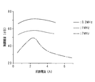
- FIG. It is a graph which shows the intensity
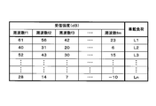
- 3 is a chart illustrating contents stored in a ROM in advance by the in-vehicle load control device according to the first embodiment.
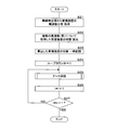
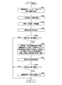
- 3 is a flowchart illustrating a processing procedure of a CPU that controls off a current flowing through an in-vehicle load by the in-vehicle load control device according to the first embodiment.
- 6 is a block diagram illustrating a configuration example of an in-vehicle load control device according to Embodiment 2.
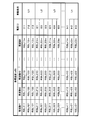
- 6 is a chart illustrating contents stored in a ROM in advance by the in-vehicle load control device according to the second embodiment.
- 7 is a flowchart illustrating a processing procedure of a CPU that controls off a current flowing through an in-vehicle load by the in-vehicle load control device according to the second embodiment.
- 10 is a flowchart illustrating a processing procedure of a CPU according to an arc extinguishing subroutine in the second embodiment.
- 10 is a flowchart illustrating a processing procedure of a CPU according to an arc extinguishing subroutine in the third embodiment.
- FIG. 1 is a block diagram illustrating a configuration example of the in-vehicle load control device according to the first embodiment.
- reference numeral 100a denotes an in-vehicle load control device mounted on a vehicle.
- the in-vehicle load control device 100a is a P-channel type MOSFET (Metal Oxide) that turns on and off currents flowing in the in-vehicle loads L1, L2, and L3 via the connector 2.
- MOSFET Metal Oxide
- FET Semiconductor Field Effect Transistor
- the in-vehicle loads L1, L2, and L3 are large current loads such as headlights, room lamps, power steering, and defoggers.
- the FETs 31, 32, and 33 and the control unit 40a are arranged on the wiring board 1, but are not limited thereto.
- Each FET may be an N-channel type, or may be another switch such as an IGBT (Insulated Gate Bipolar Transistor) or a semiconductor relay.
- the number of FETs, that is, the number of on-vehicle loads is not limited to three, and may be one, two, or n (n is a natural number of 4 or more).
- the connector 2 has a plug 20 on the wire harness side fitted to a receptacle 10 disposed on the wiring board 1.
- a configuration in which a receptacle on the wire harness side is fitted to a plug disposed on the wiring board 1 may be employed.
- the receptacle 10 of the connector 2 may not be disposed on the wiring board 1, and the entire connector 2 may be disposed outside the in-vehicle load control device 100a.
- the receptacle 10 has terminals 11, 12, and 13 connected to the drains of the FETs 31, 32, and 33, respectively.
- the terminals 11, 12, and 13 may be accommodated in two or more receptacles.
- Plug 20 has terminals 21, 22 and 23 connected to in-vehicle loads L1, L2 and L3, respectively.
- the terminals 21, 22 and 23 may be accommodated in two or more plugs.
- Each of the terminals 11, 21, terminals 12, 22 and terminals 13, 33 corresponds to a terminal pair, and is electrically connected to the receptacle 10 by fitting the plug 20 on the wire harness side.
- resistors R1, R2, and R3 are connected between the drain and the gate, and each drain is connected to the power source PS.
- the drains of the FETs 31, 32, and 33 may be connected to different power sources.
- the control unit 40a has a central processing unit (CPU) 41 that is the core of various controls in the in-vehicle load control device 100a.
- the CPU 41 stores a ROM (Read ⁇ ⁇ Only Memory) that stores information such as a control program and a frequency distribution acquired in advance. : Equivalent to a storage unit) 42, a RAM (Random Access Memory) 43 for storing temporarily generated information, and a timer 44 for measuring various times.
- the CPU 41 also includes an output unit 45 for outputting control signals to the gates of the FETs 31, 32, and 33, and a wireless detection unit 46 that receives electromagnetic waves through the antennas 461, 462, and 463 and detects the frequency distribution of the received intensity. And are connected by bus.
- the antennas 461, 462, and 463 are formed on the wiring board 1 in the vicinity of the terminals 11, 12, and 13, but the invention is not limited to this, and the wiring board 1 is located at a position separated from the wiring board 1. 1 may be relatively fixed.
- the number of antennas is not limited to three, and may be one, two, or four or more. In particular, when the terminals 11, 12 and 13 are accommodated in different connectors, different antennas may be arranged for each terminal.
- the antennas 461, 462, and 463 are, for example, magnetic field type loop antennas, which capture electromagnetic waves having a wavelength sufficiently longer than the wavelength corresponding to the size in a wide band and generate a voltage substantially proportional to the magnetic field.
- the type of antenna is not limited to this, and any type of antenna is acceptable.
- the wireless detection unit 46 includes wireless modules (not shown) corresponding to a plurality of different frequencies (or frequency bands), and each wireless module receives a relative received power at a specific frequency (or frequency band). Detect as.
- the frequency distribution detected by the wireless detection unit 46 is represented by a set of reception strengths detected by each wireless module. That is, the frequency distribution mentioned here is the reception intensity itself at a plurality of different frequencies (or frequency bands), and even if the distribution characteristics (that is, frequency characteristics) of the reception intensity are the same, the frequency distribution is the same at the same frequency (or frequency band). When the received intensity is different, it is handled as a different frequency distribution.
- arc discharge may occur between the terminals 11 and 21, between the terminals 12 and 22, and between the terminals 13 and 23. If arc discharge occurs in the vicinity of the electronic circuit, the electronic circuit may malfunction due to the influence of electromagnetic waves due to the arc discharge. The terminal where the arc discharge has occurred may be damaged, and it is preferable to extinguish the generated arc discharge immediately.
- FIG. 2 is a graph showing the intensity of electromagnetic waves generated by arc discharge (excerpted from Takagi S., “Arc discharge phenomenon of electrical contacts”, Corona, February 1995, p132-133).
- the horizontal axis in FIG. 2 represents the circuit current (A) flowing through the electrical contact when arc discharge occurs, and the vertical axis represents the relative intensity (dB) of electromagnetic waves, that is, radio noise.
- the curves shown by the solid line, the broken line, and the alternate long and short dash line in FIG. 2 indicate the general relationship between the circuit current and the radio noise for frequencies of 0.2 MHz, 1 MHz, and 7 MHz.
- the intensity of the radio noise due to arc discharge is approximately inversely proportional to the frequency, and exhibits a so-called 1 / f noise characteristic. Further, the intensity of the radio noise for each frequency is maximum at 2 to 3A, and particularly on the high frequency side, the degree of the radio noise intensity greatly depends on the magnitude of the circuit current. From this, the frequency distribution of the radio noise due to arc discharge generated between the terminals 11 and 21, between the terminals 12 and 22, and between the terminals 13 and 23 may vary depending on the current flowing through the in-vehicle loads L1, L2, and L3. I understand.
- the directivities of the antennas 461, 462, and 463 that capture radio noise generated by arc discharge are not uniform in all directions, and the antennas 461, 462, and 463, the terminals 11 and 21, the terminals 12, 22 and the terminals 13, The positional relationship with 23 is also different from each other. For this reason, even if the currents flowing through the in-vehicle loads L1, L2, and L3 are constant, the frequency distribution of the received intensity detected by the wireless detection unit 46 for the radio noise due to arc discharge is determined by the in-vehicle loads L1, L2, and L3. It will be different. Actually, it is conceivable that the frequency distribution of the received intensity changes more variously depending on the configurations of the terminals 11 and 21, the terminals 12 and 22 and the terminals 13 and 23, the currents flowing through the terminals, and the like.
- the frequency distribution of the received intensity detected by the wireless detection unit 46 by generating arc discharge in advance between the terminals 11 and 21, between the terminals 12 and 22, and between the terminals 13 and 23 corresponds to the in-vehicle loads L1, L2, and L3.
- FIG. 3 is a chart illustrating contents stored in the ROM 42 in advance by the in-vehicle load control device 100a according to the first embodiment.
- frequencies f1, f2, f3, .. fm (m is a natural number of 4 or more) for each of the on-vehicle loads L1, L2, L3,..., And Ln (n is a natural number of 4 or more: not shown after L4).
- the logarithm of the reception intensity in the frequency band centered on the frequencies f1, f2, f3,... Fm may be stored, or the reception intensity before taking the logarithm may be stored. You may remember.
- the reception strength is acquired in advance, if the reception strength changes with time, the acquisition timing may be determined as appropriate. If the number of on-board loads is three or less, unnecessary rows in the chart shown in FIG. 3 may be deleted according to the number of on-board loads.
- the received intensity at frequencies f1, f2, f3,... Fm is stored as 61, 56, 42,.
- the received intensity is stored as 40, 31, 20,... 6 (dB) in association with the vehicle load L2, and the received intensity is 52, 43, 30,. dB) is stored.
- the reception intensity is stored as 28, 14, 7,... -10 (dB) in association with the in-vehicle load Ln.
- FIG. 4 is a flowchart showing a processing procedure of the CPU 41 for controlling the current flowing through the in-vehicle loads L1, L2,..., And Ln to be off in the in-vehicle load control apparatus 100a according to the first embodiment.
- the process shown in FIG. 4 is activated periodically, for example, every 10 ms, but the activation period is not limited to 10 ms, and may be activated aperiodically.
- the currents flowing in the vehicle loads L1, L2,..., And Ln are already controlled to be on.
- the CPU 41 acquires the reception intensity from the wireless detection unit 46, that is, the reception intensity for a plurality of frequencies (or frequency bands) (S11: corresponding to the acquisition unit) and acquires the received intensity.
- the logarithm of reception intensity is calculated (S12).
- step S12 may be omitted.
- the CPU 41 initializes the loop counter i to 1 (S13), and calculates the difference between the logarithm of the reception intensity calculated in step S12 and the logarithm of the reception intensity stored in the ROM 42 corresponding to the in-vehicle load Li. Calculation is performed for each frequency (or frequency band) from frequency f1 to frequency fm (S14), and a total value of the calculated differences is calculated (S15).
- the CPU 41 determines whether or not the calculated total value is smaller than the first threshold value (S16). If the calculated total value is smaller than the first threshold value (S16: YES), the FETi (FET4 and later are not shown) using the output unit 45. ) Is turned off to turn off the current flowing through the in-vehicle load Li (S17: corresponding to the current off portion), and the processing of FIG. Steps S14 to S16 described above correspond to the collating unit. In steps S15 and S16, the total value of the differences is compared with the first threshold value. However, it is determined whether each difference is smaller than the first threshold value (for example, a value of about 1 to 2 dB). May be.
- the first threshold value for example, a value of about 1 to 2 dB. May be.
- the CPU 41 increments the loop counter i by 1 (S18), and whether i is n + 1, that is, obtained from the wireless detection unit 46. It is determined whether or not collation between the received intensity and the received intensity stored in the ROM 42 has been completed for all vehicle loads (S19).
- the loop counter i is n + 1 (S19: YES)
- the CPU 41 ends the process of FIG. 4, and when i is not n + 1 (S19: NO), the CPU 41 moves the process to step S14 to continue the collation.
- arcing is performed in advance between the terminals 11 and 21, between the terminals 12 and 22, and between the terminals 13 and 23 of the connector 2 that relays the connection with the on-vehicle loads L 1, L 2, and L 3.
- the discharge is generated, the electromagnetic wave caused by the arc discharge is received by the wireless detection unit 46, the frequency distribution of the received intensity is detected, and the detected frequency distribution is stored in the ROM 42 in association with the in-vehicle loads L1, L2, and L3. .
- the frequency distribution acquired every 10 ms from the wireless detection unit 46 and the frequency distribution stored in the ROM 42 are collated, and the current flowing through the in-vehicle load corresponding to the frequency distribution with which the collation is matched is turned off.
- the frequency distribution acquired when the arc discharge actually occurs between the terminals 11 and 21, between the terminals 12 and 22, and between the terminals 13 and 23 matches the frequency distribution stored in the ROM 42 in advance.
- the in-vehicle load corresponding to the frequency distribution with which matching is matched is specified, the current to the specified in-vehicle load is turned off, and the arc is extinguished. Therefore, it is possible to reliably detect and extinguish arc discharge.
- reception strength is collated from frequency f1 to frequency fm for each frequency or frequency band, it is possible to effectively collate the identity of the frequency distribution of reception strength. Become.
- the calculation for the verification can be performed by subtraction of the logarithmic value. It becomes possible.
- the logarithm of the reception strength when the logarithm of the reception strength is collated based on the first threshold, it is determined whether or not the difference of the reception strength is smaller than the first threshold for each frequency or frequency band. It is possible to determine whether or not the total value of the logarithmic difference of the reception intensity in each frequency or each frequency band is smaller than the first threshold value.
- the antennas 461, 462, 463 are formed on the wiring board 1 on which the receptacle 10 of the connector 2 and the wireless detection unit 46 are mounted, and the terminals 11, 21, the positional relationship among the terminals 12 and 22 and the terminals 13 and 33 and the antennas 461, 462, and 463 is fixed on the wiring board 1, so that the frequency distribution stored in the ROM 42 in advance and the frequency distribution detected by the wireless detection unit 46 are used. It is possible to accurately perform the collation with.
- the first embodiment is a mode in which the frequency distribution is verified without detecting the current flowing through the on-vehicle loads L1, L2,..., And Ln
- the second embodiment has the on-vehicle loads L1, L2, and In this embodiment, the current flowing through Ln is detected, and the frequency distribution to be verified is selected according to the detected current.
- FIG. 5 is a block diagram illustrating a configuration example of the on-vehicle load control device according to the second embodiment.
- reference numeral 100b denotes an in-vehicle load control device mounted on the vehicle.
- the in-vehicle load control device 100b includes FETs 31, 32, and 33 that turn on and off currents flowing through the in-vehicle loads L1, L2, and L3 via the connector 2, and in-vehicle Current sensors 51, 52, and 53 that detect currents flowing through the loads L1, L2, and L3 and output analog detection voltages, and a controller 40b that controls on / off of each FET are provided.
- the control unit 40b further includes an A / D conversion unit 47 that A / D converts the detected voltages from the current sensors 51, 52, and 53 into digital values with respect to the control unit 40a in the first embodiment.
- the / D conversion unit 47 is connected to the CPU 41 by a bus. With this configuration, the CPU 41 detects the current flowing through the in-vehicle loads L1, L2, and L3 as a digital value.
- each time the current flowing between the terminals 11 and 21, between the terminals 12 and 22,... And between the terminals 1 n and 2 n (the terminals 14 and 24 and beyond are not shown) is changed in advance in a plurality of ways.
- a discharge is generated and the wireless detector 46 detects the frequency distribution of the received intensity. Then, the detected frequency distribution of the received intensity is stored in the ROM 42 in association with the current when arc discharge occurs.
- FIG. 6 is a chart illustrating contents stored in the ROM 42 in advance by the in-vehicle load control apparatus 100b according to the second embodiment.
- the logarithms of the received intensities at frequencies f1, f2, f3,... Fm are stored for each of the on-vehicle loads L1, L2, L3,.
- Each received intensity is a logarithmic value displayed in RSL (Received Signal Level) ijk (i is a natural number of n or less: j is 1, 2 or 3: k is a natural number of m or less).
- RSLijk (dB) at frequencies f1, f2, f3,... Fm is stored in association with the current Iij for the on-vehicle load Li.
- the frequency distribution of the received intensity detected later by the wireless detection unit 46 and the frequency distribution of the received intensity stored in the ROM 42 are collated, the currents flowing in the vehicle loads L1, L2, L3,. To do. Then, the frequency distribution corresponding to the current close to the detected current out of the plurality of stored frequency distributions for each of the in-vehicle loads L1, L2, L3,..., And Ln is collated with the frequency distribution detected by the wireless detection unit 46. .
- the verification matches the on-vehicle load in which current flows through the terminal pair in which arc discharge has occurred is identified.
- FIG. 7 is a flowchart showing a processing procedure of the CPU 41 for controlling the current flowing through the vehicle loads L1, L2,..., Ln to be turned off by the vehicle load control apparatus 100b according to the second embodiment. It is a flowchart which shows the process sequence of CPU41 which concerns on the arc extinguishing subroutine in form 2.
- the processing in FIG. 7 is periodically activated, for example, every 10 ms, but is not limited thereto.
- the currents flowing in the vehicle loads L1, L2,..., And Ln are already controlled to be on.
- the CPU 41 acquires the reception intensity for the frequency distribution of reception intensity, that is, a plurality of frequencies (or frequency bands) from the wireless detection unit 46 (S21: equivalent to an acquisition unit)
- the logarithm of the acquired reception strength is calculated (S22), and the logarithm of the calculated reception strength is temporarily stored in the RAM 43 (S23).
- the CPU 41 initializes the loop counter i to 1 (S24), and calls and executes a subroutine related to arc extinguishing (S25).
- the CPU 41 increments the loop counter i by 1 (S26), and checks whether or not i is n + 1, that is, all the verifications of the reception intensity acquired from the wireless detection unit 46 and the reception intensity stored in the ROM 42. It is determined whether or not the vehicle-mounted load is completed (S27).
- the loop counter i is n + 1 (S27: YES)
- the CPU 41 ends the process of FIG. 7, and when i is not n + 1 (S27: NO), the CPU 41 moves the process to step S25 to continue the collation.
- the CPU 41 determines whether the in-vehicle load Li (i is a loop counter i when called, 1, 2,..., Or n). ) Is detected (S31: equivalent to a current detector). Thereafter, the CPU 41 sets the reception intensity corresponding to the current close to the current detected in step S31 out of the logarithm of the reception intensity temporarily stored and the logarithm of the reception intensity stored in the ROM 42 corresponding to the in-vehicle load Li. The difference from the logarithm is calculated for each frequency (or frequency band) from frequency f1 to frequency fm (S36).
- the CPU 41 calculates the total value of the calculated differences (S37), and determines whether the calculated total value is smaller than the first threshold value (S38). When the total value is not smaller than the first threshold (S38: NO), the CPU 41 returns to the called routine. On the other hand, when the total value is smaller than the first threshold value (S38: YES), the CPU 41 turns off the FETi using the output unit 45, thereby turning off the current flowing through the in-vehicle load Li (S39: the current off unit). Equivalent) Return to the called routine.
- the frequency distribution stored in the on-board loads L1, L2,..., And Ln by the ROM 42 is the terminals 11, 21, the terminals 12, 22, and the terminals 1n, 2n, respectively.
- the currents flowing in the vehicle loads L1, L2,..., And Ln are detected in time series, and the frequency distribution acquired in time series from the wireless detection unit 46 and the vehicle loads are stored in the ROM 42.
- a frequency distribution corresponding to a current close to a current detected in a time series among a plurality of frequency distributions is collated. Therefore, even when the current flowing through the vehicle loads L1, L2,..., And Ln is not constant when arc discharge occurs, the vehicle loads L1, L2,. According to the current flowing through each Ln, it is possible to extract the frequency distribution to be verified from the frequency distributions stored in the storage unit.
- the second embodiment is a mode in which the current flowing through the vehicle-mounted loads L1, L2,..., And Ln is detected, and the frequency distribution to be collated is selected according to the detected current
- the third embodiment is The frequency distribution to be collated is selected according to the current detected when the current flowing through the on-vehicle loads L1, L2,. Since the configuration of the in-vehicle load control device 100b in the third embodiment and the contents of the frequency distribution stored in the ROM 42 in advance are the same as those in the second embodiment, description thereof will be omitted.
- FIG. 9 is a flowchart showing a processing procedure of the CPU 41 according to the arc extinguishing subroutine in the third embodiment. Since the main routine is the same as that shown in FIG. 7 of the second embodiment, the description thereof is omitted. Also, the processing contents of steps S41 and S46 to S49 shown in FIG. 9 are the same as the processing contents of steps S31 and S36 to 39 shown in FIG.
- the CPU 41 calculates a current decrease rate (or decrease amount) based on the detected and temporarily stored current and the read current (S44), and the calculated decrease rate (or decrease amount) is greater than the second threshold value. It is determined whether or not it is large (S45: equivalent to a determination unit). If the calculated decrease rate (or decrease amount) is not greater than the second threshold (S45: NO), the CPU 41 returns to the called routine.
- the CPU 41 collates the frequency distribution in the same manner as steps S36 to S39 shown in FIG. 8 (S46 to S48). If the verification matches (S48: YES), the current flowing through the in-vehicle load Li is turned off (S49), and the process returns to the called routine.
- the second threshold when the decrease rate or decrease amount of the current detected for each of the on-vehicle loads L1, L2,..., And Ln is greater than the second threshold, it is acquired from the wireless detection unit 46.
- the frequency distribution is collated with the frequency distribution corresponding to the current close to the detected current among the plurality of frequency distributions stored in the ROM 42 for each of the vehicle loads L1, L2,. Therefore, since the collation is performed when the electric discharge begins to increase due to the occurrence of arc discharge at the terminals 11 and 21, the terminals 12 and 22, and the terminals 13 and 23, the collation process is narrowed down and the collation process is narrowed down. The load can be reduced.
Landscapes
- Engineering & Computer Science (AREA)
- Mechanical Engineering (AREA)
- Remote Monitoring And Control Of Power-Distribution Networks (AREA)
- Emergency Protection Circuit Devices (AREA)
- Distribution Board (AREA)
- Lighting Device Outwards From Vehicle And Optical Signal (AREA)
Abstract
コネクタの端子対に発生したアーク放電を確実に検出して消弧させることが可能な車載負荷制御装置及びコンピュータプログラムを提供する。車載負荷L1、L2及びL3との接続を中継するコネクタ2の端子11,21、端子12,22及び端子13,23に予めアーク放電を発生させ、アーク放電による電磁波を無線検出部46で受信して受信強度の周波数分布を検出し、検出した周波数分布を車載負荷L1、L2及びL3夫々に対応付けてROM42に記憶しておく。その上で、無線検出部46から時系列的に取得した周波数分布とROM42に記憶した周波数分布とを照合し、照合が一致した周波数分布に対応する車載負荷に流れる電流をオフする。
Description
本発明は、車載負荷にコネクタの端子対を介して流れる電流をオンオフする車載負荷制御装置及びコンピュータプログラムに関する。
接点を開閉する場合、接点間の電位差が所謂最小アーク電圧より大きく、且つ接点電流が最小アーク電流より大きいときに、アーク放電が発生することが知られている。特に直流電流が流れている接点を開閉する場合は、交流電流が流れている場合と比較して放電が長時間持続する。
接点間にアーク放電が発生した場合、アーク放電に伴う高熱によって、接点が酸化又は黒化したり溶着したりして損傷を来す他、電磁波ノイズが発生して周囲の電子回路に悪影響を及ぼす虞がある。このため、一旦発生したアーク放電は、できるだけ短時間のうちに消弧させることが好ましい。
例えば特許文献1には、定電流電源(又は定電圧電源)から複数のLEDを有する負荷に印加する負荷電圧(又は負荷に流れる負荷電流)を所定周期でサンプリングし、サンプリング結果が、所定電圧以上上昇(又は所定電流以上減少)したときにアーク放電が生起したと判定して、定電流電源(又は定電圧電源)を停止させるLED点灯装置が記載されている。この場合の所定電圧は、最小アーク電圧に応じて定電流電源の出力電圧が上昇するときの上昇分より低い電圧であり、最小電流は、最小アーク電圧に応じて負荷に印加される電圧が低下するときの負荷電流の減少分より少ない電流である。
しかしながら、特許文献1に記載された技術では、負荷が変動した場合にアーク放電を検出できなかったり誤検出したりする虞があった。
本発明は斯かる事情に鑑みてなされたものであり、その目的とするところは、コネクタの端子対に発生したアーク放電を確実に検出して消弧させることが可能な車載負荷制御装置及びコンピュータプログラムを提供することにある。
本発明の一態様に係る車載負荷制御装置は、1又は複数の車載負荷夫々にコネクタの端子対を介して流れる電流をオンオフする車載負荷制御装置において、電磁波を受信して受信強度の周波数分布を検出する無線検出部と、前記車載負荷夫々への電流が流れる端子対にアーク放電が発生したときに前記無線検出部で検出した周波数分布を夫々の車載負荷に対応付けて予め記憶する記憶部と、前記無線検出部で検出した周波数分布を時系列的に取得する取得部と、該取得部で取得した周波数分布及び前記記憶部に記憶した周波数分布を照合する照合部と、該照合部の照合結果が一致の場合、一致した周波数分布に対応する車載負荷に流れる電流をオフする電流オフ部とを備えることを特徴とする。
本発明の一態様に係る車載負荷制御装置は、前記照合部は、複数の異なる周波数毎又は周波数帯毎に受信強度を照合するようにしてあることを特徴とする。
本発明の一態様に係る車載負荷制御装置は、前記照合部は、前記受信強度の対数を照合するようにしてあることを特徴とする。
本発明の一態様に係る車載負荷制御装置は、前記照合部は、第1閾値に基づいて照合するようにしてあることを特徴とする。
本発明の一態様に係る車載負荷制御装置は、前記記憶部は、前記端子対に流れる複数通りの電流について夫々アーク放電が発生したときに前記無線検出部で検出した周波数分布を夫々の電流に更に対応付けて予め記憶するようにしてあり、前記車載負荷夫々に流れる電流を時系列的に検出する電流検出部を備え、前記照合部は、前記取得部で取得した周波数分布、及び前記車載負荷夫々に対応して前記記憶部に記憶されている周波数分布のうち前記電流検出部で夫々検出した電流に近い電流に対応して前記記憶部に記憶されている周波数分布を照合するようにしてあることを特徴とする。
本発明の一態様に係る車載負荷制御装置は、前記電流検出部で夫々検出した電流の減少率又は減少量を算出する算出部と、該算出部で夫々算出した減少率又は減少量が第2閾値より大きいか否かを判定する判定部とを備え、前記照合部は、前記判定部で第2閾値より大きいと夫々判定した場合に照合するようにしてあることを特徴とする。
本発明の一態様に係る車載負荷制御装置は、前記コネクタ及び無線検出部が搭載された配線基板を備え、前記無線検出部で前記電磁波を受信するためのアンテナは、前記配線基板上に形成してあることを特徴とする。
本発明の一態様に係るコンピュータプログラムは、電磁波を受信して受信強度の周波数分布を検出する無線検出部、及び1又は複数の車載負荷夫々への電流が流れるコネクタの端子対にアーク放電が発生したときに前記無線検出部で検出した周波数分布を夫々の車載負荷に対応付けて予め記憶する記憶部に接続されており、前記車載負荷夫々に流れる電流をオンオフに制御するコンピュータに、前記無線検出部の検出結果に基づいて前記コネクタに発生したアーク放電を消弧させるためのコンピュータプログラムであって、前記コンピュータを、前記無線検出部で検出した周波数分布を時系列的に取得する取得部、該取得部で取得した周波数分布及び前記記憶部に記憶された周波数分布を照合する照合部、及び該照合部での照合結果が一致の場合、一致した周波数分布に対応する車載負荷に流れる電流をオフに制御する電流オフ部として機能させることを特徴とする。
本態様にあっては、1又は複数の車載負荷夫々について、車載負荷との接続を中継するコネクタの端子対に予めアーク放電を発生させ、アーク放電による電磁波を無線検出部で受信して受信強度の周波数分布を検出し、検出した周波数分布を車載負荷夫々に対応付けて記憶部に記憶しておく。その上で、無線検出部から時系列的に取得した周波数分布と記憶部に記憶した周波数分布とを照合し、照合が一致した周波数分布に対応する車載負荷に流れる電流をオフする。
これにより、1又は複数の端子対夫々に実際にアーク放電が発生したときに取得される周波数分布と予め記憶された周波数分布とで照合が一致した場合、照合が一致した周波数分布に対応する車載負荷が特定され、特定された車載負荷への電流がオフされてアークが消弧する。
これにより、1又は複数の端子対夫々に実際にアーク放電が発生したときに取得される周波数分布と予め記憶された周波数分布とで照合が一致した場合、照合が一致した周波数分布に対応する車載負荷が特定され、特定された車載負荷への電流がオフされてアークが消弧する。
本態様にあっては、受信強度の照合を、複数の異なる周波数毎又は周波数帯毎に行うため、受信強度の周波数分布の同一性が効果的に照合される。
本態様にあっては、複数の異なる周波数毎又は周波数帯毎に受信強度の対数をとって照合を行うため、照合のための演算が対数値の減算で足りる。
本態様にあっては、受信強度の対数を第1閾値に基づいて照合する際に、例えば周波数毎又は周波数帯毎に受信強度の差分を第1閾値と比較したり、各周波数又は各周波数帯における受信強度の対数の差分の合計値を第1閾値と比較したりする。
本態様にあっては、記憶部が1又は複数の車載負荷について記憶する周波数分布は、1又は複数の端子対夫々に流れる電流を予め複数通りに変化させる都度アーク放電を発生させて無線検出部で検出した受信強度の分布であり、車載負荷夫々について複数通りの周波数分布をアーク放電が発生したときの電流に対応付けて記憶してある。その上で、1又は複数の車載負荷夫々に流れる電流を時系列的に検出し、無線検出部から時系列的に取得した周波数分布と、車載負荷夫々について記憶部に記憶されている複数の周波数分布のうち時系列的に検出した電流に近い電流に対応する周波数分布とを照合する。
これにより、アーク放電が発生するときに車載負荷に流れる電流が一定ではない場合であっても、実際にアーク放電が発生したときに車載負荷夫々に流れる電流に応じて、記憶部に記憶された周波数分布の内から照合対象とすべき周波数分布が抽出される。
これにより、アーク放電が発生するときに車載負荷に流れる電流が一定ではない場合であっても、実際にアーク放電が発生したときに車載負荷夫々に流れる電流に応じて、記憶部に記憶された周波数分布の内から照合対象とすべき周波数分布が抽出される。
本態様にあっては、1又は複数の車載負荷夫々について検出した電流の減少率又は減少量が第2閾値より大きい場合に、無線検出部から取得した周波数分布と、車載負荷夫々について記憶部に記憶されている複数の周波数分布のうち検出した電流に近い電流に対応する周波数分布とを照合する。
これにより、端子対にアーク放電が発生して端子対の電気抵抗が増大し始めたときに照合が行われるため、照合の時期及び対象が絞り込まれて照合の処理負荷が削減される。
これにより、端子対にアーク放電が発生して端子対の電気抵抗が増大し始めたときに照合が行われるため、照合の時期及び対象が絞り込まれて照合の処理負荷が削減される。
本態様にあっては、コネクタ及び無線検出部が搭載された配線基板上にアンテナが形成されており、アーク放電が発生する端子対とアンテナとの位置関係が配線基板上で固定されるため、予め記憶した周波数分布と無線検出部で検出した周波数分布との照合が精度よく行える。
上記によれば、端子対に実際にアーク放電が発生したときに取得された周波数分布と記憶された周波数分布とで分布が類似していることから照合が一致した場合、照合が一致した周波数分布に対応して記憶されている車載負荷が特定され、特定された車載負荷への電流がオフされてアークが消弧する。
従って、コネクタの端子対に発生したアーク放電を確実に検出して消弧させることが可能となる。
従って、コネクタの端子対に発生したアーク放電を確実に検出して消弧させることが可能となる。
以下、本発明をその実施の形態を示す図面に基づいて詳述する。
(実施の形態1)
図1は、実施の形態1に係る車載負荷制御装置の構成例を示すブロック図である。図中100aは車両に搭載された車載負荷制御装置であり、車載負荷制御装置100aは、コネクタ2を介して車載負荷L1、L2及びL3夫々に流れる電流をオンオフするPチャネル型のMOSFET(Metal Oxide Semiconductor Field Effect Transistor :以下単にFETという)31、32及び33と、各FETのオンオフを制御する制御部40aとを備える。車載負荷L1、L2及びL3は、例えばヘッドライト、ルームランプ、パワーステアリング、デフォッガ等の大電流負荷である。
(実施の形態1)
図1は、実施の形態1に係る車載負荷制御装置の構成例を示すブロック図である。図中100aは車両に搭載された車載負荷制御装置であり、車載負荷制御装置100aは、コネクタ2を介して車載負荷L1、L2及びL3夫々に流れる電流をオンオフするPチャネル型のMOSFET(Metal Oxide Semiconductor Field Effect Transistor :以下単にFETという)31、32及び33と、各FETのオンオフを制御する制御部40aとを備える。車載負荷L1、L2及びL3は、例えばヘッドライト、ルームランプ、パワーステアリング、デフォッガ等の大電流負荷である。
FET31、32及び33と制御部40aとは配線基板1上に配置されているが、これに限定されるものではない。各FETはNチャネル型でもよく、IGBT(Insulated Gate Bipolar Transistor )、半導体リレー等の他のスイッチであってもよい。FETの数、即ち車載負荷の数は3つに限定されず、1つ、2つ又はn個(nは4以上の自然数)であってもよい。
コネクタ2は、配線基板1上に配されたレセプタクル10にワイヤハーネス側のプラグ20が嵌合している。配線基板1上に配置されたプラグにワイヤハーネス側のレセプタクルが嵌合する構成であってもよい。また、コネクタ2のレセプタクル10が配線基板1上に配置されていなくてもよく、コネクタ2全体が車載負荷制御装置100aの外部に配置されていてもよい。
レセプタクル10は、FET31、32及び33夫々のドレインに接続された端子11、12及び13を有する。端子11、12及び13が2つ以上のレセプタクルに分けて収容されていてもよい。プラグ20は、車載負荷L1、L2及びL3夫々に接続された端子21、22及び23を有する。端子21、22及び23が2つ以上のプラグに分けて収容されていてもよい。端子11,21、端子12,22及び端子13,33夫々は端子対に相当し、レセプタクル10にワイヤハーネス側のプラグ20が嵌合することにより互いに電気的に接続される。
FET31、32及び33夫々は、ドレインとゲートとの間に抵抗器R1、R2及びR3が接続されており、夫々のドレインが電源PSに接続されている。FET31、32及び33のドレインが異なる電源に接続されていてもよい。
制御部40aは、車載負荷制御装置100aにおける各種制御の中核となるCPU(Central Processing Unit )41を有し、CPU41は、制御プログラム、予め取得した周波数分布等の情報を記憶するROM(Read Only Memory:記憶部に相当)42、一時的に発生した情報を記憶するRAM(Random Access Memory )43、及び各種の時間を計時するタイマ44とバス接続されている。
CPU41には、また、FET31、32及び33のゲートに制御信号を出力するための出力部45と、アンテナ461、462及び463により電磁波を受信して受信強度の周波数分布を検出する無線検出部46とがバス接続されている。
アンテナ461、462及び463夫々は、端子11、12及び13の近傍の配線基板1上に形成されているが、これに限定されるものではなく、配線基板1とは離隔した位置に、配線基板1に対して相対的に固定されていてもよい。アンテナの数は3つに限定されず、1つ、2つ又は4つ以上であってもよい。特に端子11、12及び13が相異なるコネクタに収容されている場合は、端子毎に異なるアンテナを配置してもよい。
アンテナ461、462及び463は、例えば磁界型のループアンテナであり、サイズに対応する波長より十分に長い波長の電磁波を広帯域に捕捉して磁界に略比例する電圧を発生する。アンテナのタイプはこれに限定されるものではなく、任意のタイプのアンテナが許容される。
無線検出部46は、複数の異なる周波数(又は周波数帯)夫々に対応する無線モジュール(不図示)を含み、各無線モジュールが夫々固有の周波数(又は周波数帯)における相対的な受信電力を受信強度として検出する。無線検出部46が検出する周波数分布は、各無線モジュールが検出する受信強度の集合によって表される。つまり、ここで言う周波数分布は、複数の異なる周波数(又は周波数帯)における受信強度そのものであり、受信強度の分布特性(即ち周波数特性)が同一であっても、同じ周波数(又は周波数帯)における受信強度が異なる場合は、異なる周波数分布として扱う。
上述の構成において、例えば車載負荷L1、L2及びL3への通電中にプラグ20及びレセプタクル10の嵌合を解除する場合、又はプラグ20及びレセプタクル10の嵌合が不完全な状態で車両が走行した場合、端子11,21間、端子12,22間及び端子13,23間でアーク放電が発生することがある。電子回路の近傍でアーク放電が発生した場合、アーク放電による電磁波の影響を受けて電子回路が誤動作を起こす虞がある。アーク放電が発生した端子が損傷を受ける可能性もあり、発生したアーク放電を早急に消弧させることが好ましい。
図2は、アーク放電により発生する電磁波の強度を示すグラフである(高木相著,「電気接点のアーク放電現象」,コロナ社,1995年2月,p132-133より抜粋)。図2の横軸は、アーク放電が発生したときに電気接点に流れている回路電流(A)を表し、縦軸は電磁波、即ち無線雑音の相対的な強度(dB)を表す。図2に実線、破線及び一点鎖線夫々にて示す曲線は、0.2MHz、1MHz及び7MHzの周波数について、回路電流と無線雑音との一般的な関係を示すものである。
図2のグラフによって示される全体的な傾向として、アーク放電による無線雑音は、強度が周波数に略反比例しており、いわゆる1/f雑音特性を呈する。また、各周波数についての無線雑音の強度は、2~3Aで最大となっており、特に高域側では、無線雑音の強度が回路電流の大きさに依存する度合いが大きい。このことから、端子11,21間、端子12,22間及び端子13,23間夫々に発生するアーク放電による無線雑音の周波数分布は、車載負荷L1、L2及びL3に流れる電流によって変動することが分かる。
一方、アーク放電により発生する無線雑音を捕捉するアンテナ461、462及び463の指向性は、全方位について均等ではなく、アンテナ461、462及び463と端子11,21、端子12,22及び端子13,23との位置関係も相互に異なっている。このため、車載負荷L1、L2及びL3に流れる電流が仮に一定であったとしても、アーク放電による無線雑音について無線検出部46が検出する受信強度の周波数分布は、車載負荷L1、L2及びL3によって相異なるものとなる。実際には端子11,21、端子12,22及び端子13,23夫々の構成、夫々に流れる電流等が異なることにより、上記の受信強度の周波数分布は更に多様に変化することが考えられる。
そこで、端子11,21間、端子12,22間及び端子13,23間夫々に予めアーク放電を発生させて無線検出部46で検出した受信強度の周波数分布を車載負荷L1、L2及びL3に対応付けてROM42に記憶しておき、後に無線検出部46で検出した受信強度の周波数分布と照合することにより、アーク放電が発生した端子対を介して電流が流れている車載負荷を特定することができる。そして、特定した車載負荷に流れる電流をFETでオフすることにより、アーク放電を消弧させることができる。
図3は、実施の形態1に係る車載負荷制御装置100aで予めROM42に記憶した内容を例示する図表である。ここでは、車載負荷L1、L2、L3、・・及びLn(nは4以上の自然数:L4以降は不図示)の夫々について、周波数f1,f2,f3,・・fm(mは4以上の自然数)における受信強度の対数を記憶してあるが、周波数f1,f2,f3,・・fmを中心とする周波数帯における受信強度の対数を記憶してもよいし、対数をとる前の受信強度を記憶してもよい。予め受信強度を取得する際に、受信強度が時間の経過と共に変化する場合は、適宜取得のタイミングを定めればよい。また、車載負荷の数が3つ以下の場合は、車載負荷の数に応じて図3に示す図表における不要な行を削除すればよい。
具体的に図3では、車載負荷L1に対応付けて、周波数f1,f2,f3,・・fmにおける受信強度が61,56,42,・・23(dB)と記憶されている。同様に車載負荷L2に対応付けて受信強度が40,31,20,・・6(dB)と記憶されており、車載負荷L3に対応付けて受信強度が52,43,30,・・15(dB)と記憶されている。・・・更に、車載負荷Lnに対応付けて受信強度が28,14,7,・・-10(dB)と記憶されている。
以下では、上述した制御部40aの動作を、それを示すフローチャートを用いて説明する。以下に示す処理は、ROM42に予め格納されている制御プログラムに従って、CPU41により実行される。
図4は、実施の形態1に係る車載負荷制御装置100aで車載負荷L1、L2、・・及びLnに流れる電流をオフに制御するCPU41の処理手順を示すフローチャートである。図4に示す処理は、例えば10ms毎に周期的に起動されるが、起動周期が10msに限定されるものではなく、非周期的に起動されるようにしてもよい。車載負荷L1、L2、・・及びLnに流れる電流は既にオンに制御されている。
図4は、実施の形態1に係る車載負荷制御装置100aで車載負荷L1、L2、・・及びLnに流れる電流をオフに制御するCPU41の処理手順を示すフローチャートである。図4に示す処理は、例えば10ms毎に周期的に起動されるが、起動周期が10msに限定されるものではなく、非周期的に起動されるようにしてもよい。車載負荷L1、L2、・・及びLnに流れる電流は既にオンに制御されている。
図4の処理が起動された場合、CPU41は、無線検出部46から受信強度の周波数分布、即ち複数の周波数(又は周波数帯)について受信強度を取得し(S11:取得部に相当)、取得した受信強度の対数を算出する(S12)。無線検出部46から受信強度の対数が取得される場合は、ステップS12を省略すればよい。
次いで、CPU41は、ループカウンタiを1に初期化し(S13)、ステップS12で算出した受信強度の対数と、車載負荷Liに対応してROM42に記憶されている受信強度の対数との差分を、周波数f1から周波数fmまで周波数(又は周波数帯)毎に算出して(S14)、算出した各差分の合計値を算出する(S15)。
その後、CPU41は、算出した合計値が第1閾値より小さいか否かを判定し(S16)、第1閾値より小さい場合(S16:YES)、出力部45を用いてFETi(FET4以降は不図示)をオフすることにより、車載負荷Liに流れる電流をオフして(S17:電流オフ部に相当)図4の処理を終了する。上述のステップS14からS16までが照合部に相当する。
なお、ステップS15及びS16では、各差分の合計値と第1閾値とを比較したが、各差分の夫々が第1閾値(例えば1~2dB程度の値)より小さいか否かを判定するようにしてもよい。
なお、ステップS15及びS16では、各差分の合計値と第1閾値とを比較したが、各差分の夫々が第1閾値(例えば1~2dB程度の値)より小さいか否かを判定するようにしてもよい。
算出した合計値が第1閾値より小さくない場合(S16:NO)、CPU41は、ループカウンタiを1だけインクリメントし(S18)、iがn+1であるか否か、即ち無線検出部46から取得した受信強度とROM42に記憶されている受信強度との照合を全ての車載負荷について完了したか否かを判定する(S19)。CPU41は、ループカウンタiがn+1である場合(S19:YES)、図4の処理を終了し、iがn+1ではない場合(S19:NO)、照合を継続するためにステップS14に処理を移す。
以上のように本実施の形態1によれば、車載負荷L1、L2及びL3夫々との接続を中継するコネクタ2の端子11,21間、端子12,22間及び端子13,23間に予めアーク放電を発生させ、アーク放電による電磁波を無線検出部46で受信して受信強度の周波数分布を検出し、検出した周波数分布を車載負荷L1、L2及びL3夫々に対応付けてROM42に記憶しておく。その上で、無線検出部46から10ms毎に取得した周波数分布とROM42に記憶した周波数分布とを照合し、照合が一致した周波数分布に対応する車載負荷に流れる電流をオフする。
これにより、端子11,21間、端子12,22間及び端子13,23間夫々に実際にアーク放電が発生したときに取得される周波数分布と予めROM42に記憶された周波数分布とで照合が一致した場合、照合が一致した周波数分布に対応する車載負荷が特定され、特定された車載負荷への電流がオフされてアークが消弧する。
従って、アーク放電を確実に検出して消弧させることが可能となる。
これにより、端子11,21間、端子12,22間及び端子13,23間夫々に実際にアーク放電が発生したときに取得される周波数分布と予めROM42に記憶された周波数分布とで照合が一致した場合、照合が一致した周波数分布に対応する車載負荷が特定され、特定された車載負荷への電流がオフされてアークが消弧する。
従って、アーク放電を確実に検出して消弧させることが可能となる。
また、実施の形態1によれば、受信強度の照合を、周波数f1から周波数fmまで周波数毎又は周波数帯毎に行うため、受信強度の周波数分布の同一性を効果的に照合することが可能となる。
更に、実施の形態1によれば、周波数f1から周波数fmまで周波数毎又は周波数帯毎に受信強度の対数をとって周波数分布の照合を行うため、照合のための演算を対数値の減算で済ますことが可能となる。
更にまた、実施の形態1によれば、受信強度の対数を第1閾値に基づいて照合する際に、周波数毎又は周波数帯毎に受信強度の差分が第1閾値より小さいか否かを判定したり、各周波数又は各周波数帯における受信強度の対数の差分の合計値が第1閾値より小さいか否かを判定したりすることが可能である。
更にまた、実施の形態1によれば、コネクタ2のレセプタクル10及び無線検出部46が搭載された配線基板1上にアンテナ461,462,463が形成されており、アーク放電が発生する端子11,21、端子12,22及び端子13,33とアンテナ461,462,463との位置関係が配線基板1上で固定されるため、予めROM42に記憶した周波数分布と無線検出部46で検出した周波数分布との照合を精度よく行うことが可能となる。
(実施の形態2)
実施の形態1が、車載負荷L1、L2、・・及びLnに流れる電流を検出することなく周波数分布の照合を行う形態であるのに対し、実施の形態2は、車載負荷L1、L2、及びLnに流れる電流を検出し、検出した電流に応じて、照合すべき周波数分布を選択する形態である。
実施の形態1が、車載負荷L1、L2、・・及びLnに流れる電流を検出することなく周波数分布の照合を行う形態であるのに対し、実施の形態2は、車載負荷L1、L2、及びLnに流れる電流を検出し、検出した電流に応じて、照合すべき周波数分布を選択する形態である。
図5は、実施の形態2に係る車載負荷制御装置の構成例を示すブロック図である。図中100bは車両に搭載された車載負荷制御装置であり、車載負荷制御装置100bは、コネクタ2を介して車載負荷L1、L2及びL3夫々に流れる電流をオンオフするFET31、32及び33と、車載負荷L1、L2及びL3夫々に流れる電流を検出してアナログの検出電圧を出力する電流センサ51、52及び53と、各FETのオンオフを制御する制御部40bとを備える。
制御部40bは、実施の形態1における制御部40aに対して、電流センサ51、52及び53からの検出電圧をデジタル値にA/D変換するA/D変換部47を更に有し、該A/D変換部47がCPU41にバス接続されている。この構成により、CPU41は、車載負荷L1、L2及びL3に流れる電流をデジタル値で検出する。
その他、実施の形態1に対応する箇所には同様の符号を付してその説明を省略する。
本実施の形態2では、端子11,21間、端子12,22間、・・及び端子1n,2n間(端子14,24以降は不図示)夫々に流れる電流を予め複数通りに変化させる都度アーク放電を発生させて無線検出部46で受信強度の周波数分布を検出する。そして、検出した受信強度の周波数分布をアーク放電が発生したときの電流に対応付けてROM42に記憶しておく。
図6は、実施の形態2に係る車載負荷制御装置100bで予めROM42に記憶した内容を例示する図表である。ここでは、車載負荷L1、L2、L3、・・及びLnの夫々について、3通りの電流に夫々対応付けて周波数f1,f2,f3,・・fmにおける受信強度の対数を記憶してある。各受信強度は、RSL(Received Signal Level )ijk(iはn以下の自然数:jは1、2又は3:kはm以下の自然数)で表示される対数値である。具体的には、車載負荷Liについて、周波数f1,f2,f3,・・fmにおける受信強度RSLijk(dB)が電流Iijに対応付けて記憶されている。
後に無線検出部46で検出した受信強度の周波数分布とROM42に記憶されている受信強度の周波数分布とを照合する場合は、車載負荷L1、L2、L3、・・及びLn夫々に流れる電流を検出する。そして、車載負荷L1、L2、L3、・・及びLn夫々について複数記憶されている周波数分布のうち検出した電流に近い電流に対応する周波数分布と無線検出部46で検出した周波数分布とを照合する。照合が一致した場合に、アーク放電が発生した端子対を介して電流が流れている車載負荷が特定される。
以下では、上述した制御部40bの動作を、それを示すフローチャートを用いて説明する。
図7は、実施の形態2に係る車載負荷制御装置100bで車載負荷L1、L2、・・及びLnに流れる電流をオフに制御するCPU41の処理手順を示すフローチャートであり、図8は、実施の形態2におけるアーク消弧のサブルーチンに係るCPU41の処理手順を示すフローチャートである。図7の処理は、例えば10ms毎に周期的に起動されるが、これに限定されるものではない。車載負荷L1、L2、・・及びLnに流れる電流は既にオンに制御されている。
図7は、実施の形態2に係る車載負荷制御装置100bで車載負荷L1、L2、・・及びLnに流れる電流をオフに制御するCPU41の処理手順を示すフローチャートであり、図8は、実施の形態2におけるアーク消弧のサブルーチンに係るCPU41の処理手順を示すフローチャートである。図7の処理は、例えば10ms毎に周期的に起動されるが、これに限定されるものではない。車載負荷L1、L2、・・及びLnに流れる電流は既にオンに制御されている。
図7に示すメインルーチンの処理が起動された場合、CPU41は、無線検出部46から受信強度の周波数分布、即ち複数の周波数(又は周波数帯)について受信強度を取得し(S21:取得部に相当)、取得した受信強度の対数を算出し(S22)、更に算出した受信強度の対数をRAM43に一時記憶する(S23)。その後、CPU41は、ループカウンタiを1に初期化し(S24)、アーク消弧に係るサブルーチンを呼び出して実行する(S25)。
次いで、CPU41は、ループカウンタiを1だけインクリメントし(S26)、iがn+1であるか否か、即ち無線検出部46から取得した受信強度とROM42に記憶されている受信強度との照合を全ての車載負荷について完了したか否かを判定する(S27)。CPU41は、ループカウンタiがn+1である場合(S27:YES)、図7の処理を終了し、iがn+1ではない場合(S27:NO)、照合を継続するためにステップS25に処理を移す。
次に、図8に示すアーク消弧に係るサブルーチンが呼び出された場合、CPU41は、車載負荷Li(iは呼び出されたときのループカウンタiであり、1、2、・・又はnの何れか)に流れる電流を検出する(S31:電流検出部に相当)。その後、CPU41は、一時記憶してある受信強度の対数と、車載負荷Liに対応してROM42に記憶されている受信強度の対数のうちステップS31で検出した電流に近い電流に対応する受信強度の対数との差分を周波数f1から周波数fmまで周波数(又は周波数帯)毎に算出する(S36)。
例えば、車載負荷L1に流れる電流が2.2Aと検出され、I11=1A,I12=2A,I13=3AとROM42に記憶されている場合、一時記憶してある受信強度の対数と、検出した電流に近いI12に対応する受信強度であるRSL121,RSL122,RSL123,・・RAL12mとの差分を、周波数f1,f2,f3,・・fm毎に算出する。
次いで、CPU41は、算出した各差分の合計値を算出し(S37)、算出した合計値が第1閾値より小さいか否かを判定する(S38)。合計値が第1閾値より小さくない場合(S38:NO)、CPU41は、呼び出されたルーチンにリターンする。一方、合計値が第1閾値より小さい場合(S38:YES)、CPU41は、出力部45を用いてFETiをオフすることにより、車載負荷Liに流れる電流をオフして(S39:電流オフ部に相当)呼び出されたルーチンにリターンする。
以上のように本実施の形態2によれば、ROM42が車載負荷L1、L2、・・及びLnについて記憶する周波数分布は、端子11,21、端子12,22、・・及び端子1n,2n夫々に流れる電流を予め複数通りに変化させる都度アーク放電を発生させて無線検出部46で検出した受信強度の分布であり、車載負荷L1、L2、・・及びLn夫々について複数通りの周波数分布をアーク放電が発生したときの電流に対応付けて記憶してある。その上で、車載負荷L1、L2、・・及びLn夫々に流れる電流を時系列的に検出し、無線検出部46から時系列的に取得した周波数分布と、車載負荷夫々についてROM42に記憶されている複数の周波数分布のうち時系列的に検出した電流に近い電流に対応する周波数分布とを照合する。
従って、アーク放電が発生するときに車載負荷L1、L2、・・及びLnに流れる電流が一定ではない場合であっても、実際にアーク放電が発生したときに車載負荷L1、L2、・・及びLn夫々に流れる電流に応じて、記憶部に記憶された周波数分布の内から照合対象とすべき周波数分布を抽出することが可能となる。
従って、アーク放電が発生するときに車載負荷L1、L2、・・及びLnに流れる電流が一定ではない場合であっても、実際にアーク放電が発生したときに車載負荷L1、L2、・・及びLn夫々に流れる電流に応じて、記憶部に記憶された周波数分布の内から照合対象とすべき周波数分布を抽出することが可能となる。
(実施の形態3)
実施の形態2が、車載負荷L1、L2、・・及びLnに流れる電流を検出し、検出した電流に応じて、照合すべき周波数分布を選択する形態であるのに対し、実施の形態3は、車載負荷L1、L2、・・及びLnに流れる電流が一定の割合又は一定量だけ減少したときに検出した電流に応じて、照合すべき周波数分布を選択する形態である。
実施の形態3における車載負荷制御装置100bの構成と、予めROM42に記憶する周波数分布の内容とは実施の形態2の場合と同様であるため、これらの説明を省略する。
実施の形態2が、車載負荷L1、L2、・・及びLnに流れる電流を検出し、検出した電流に応じて、照合すべき周波数分布を選択する形態であるのに対し、実施の形態3は、車載負荷L1、L2、・・及びLnに流れる電流が一定の割合又は一定量だけ減少したときに検出した電流に応じて、照合すべき周波数分布を選択する形態である。
実施の形態3における車載負荷制御装置100bの構成と、予めROM42に記憶する周波数分布の内容とは実施の形態2の場合と同様であるため、これらの説明を省略する。
後に無線検出部46で検出した受信強度の周波数分布とROM42に記憶されている受信強度の周波数分布とを照合する場合は、車載負荷L1、L2、L3、・・及びLn夫々に流れる電流の減少率又は減少量を検出し、検出した減少率又は減少量が第2閾値より大きいことを確認する。そして、車載負荷L1、L2、L3、・・及びLn夫々について複数記憶されている周波数分布のうち上記の確認を行ったときの電流に近い電流に対応する周波数分布と無線検出部46で検出した周波数分布とを照合する。照合が一致した場合に、アーク放電が発生した端子対を介して電流が流れている車載負荷が特定される。
以下では、上述した制御部40bの動作を、それを示すフローチャートを用いて説明する。
図9は、実施の形態3におけるアーク消弧のサブルーチンに係るCPU41の処理手順を示すフローチャートである。メインルーチンは、実施の形態2の図7に示すものと同様であるため、その説明を省略する。また、図9に示すステップS41及びS46~S49の処理内容は、実施の形態2の図8に示すステップS31及びS36~39の処理内容と同様であるため、説明の大部分を省略する。
図9は、実施の形態3におけるアーク消弧のサブルーチンに係るCPU41の処理手順を示すフローチャートである。メインルーチンは、実施の形態2の図7に示すものと同様であるため、その説明を省略する。また、図9に示すステップS41及びS46~S49の処理内容は、実施の形態2の図8に示すステップS31及びS36~39の処理内容と同様であるため、説明の大部分を省略する。
アーク消弧に係るサブルーチンが呼び出されて車載負荷Li(iは1、2、・・又はnの何れか)に流れる電流を検出した(S41)後、CPU41は、サブルーチンが前回呼び出されたときにRAM43に一時記憶した電流を読み出し(S42)、検出した電流を一時記憶する(S43)。これにより、一時記憶される電流が検出した最新の電流に書き換わる。
次いで、CPU41は、検出して一時記憶した電流と読み出した電流とに基づいて電流の減少率(又は減少量)を算出し(S44)、算出した減少率(又は減少量)が第2閾値より大きいか否かを判定する(S45:判定部に相当)。算出した減少率(又は減少量)が第2閾値より大きくない場合(S45:NO)、CPU41は、呼び出されたルーチンにリターンする。
一方、算出した減少率(又は減少量)が第2閾値より大きい場合(S45:YES)、CPU41は、図8に示すステップS36~S39と同様にして周波数分布の照合を行い(S46~S48)、照合が一致した場合(S48:YES)、車載負荷Liに流れる電流をオフして(S49)呼び出されたルーチンにリターンする。
以上のように本実施の形態3によれば、車載負荷L1、L2、・・及びLn夫々について検出した電流の減少率又は減少量が第2閾値より大きい場合に、無線検出部46から取得した周波数分布と、車載負荷L1、L2、・・及びLn夫々についてROM42に記憶されている複数の周波数分布のうち検出した電流に近い電流に対応する周波数分布とを照合する。
従って、端子11,21、端子12,22及び端子13,23夫々にアーク放電が発生して電気抵抗が増大し始めたときに照合が行われるため、照合の時期と対象を絞り込んで照合の処理負荷を削減することが可能となる。
従って、端子11,21、端子12,22及び端子13,23夫々にアーク放電が発生して電気抵抗が増大し始めたときに照合が行われるため、照合の時期と対象を絞り込んで照合の処理負荷を削減することが可能となる。
今回開示された実施の形態は、全ての点で例示であって、制限的なものではないと考えられるべきである。本発明の範囲は、上述した意味ではなく、請求の範囲によって示され、請求の範囲と均等の意味及び範囲内での全ての変更が含まれることが意図される。また、各実施の形態で記載されている技術的特徴は、お互いに組み合わせることが可能である。
100a、100b 車載負荷制御装置
1 配線基板
2 コネクタ
10 レセプタクル
11、12、13 端子
20 プラグ
21、22、23 端子
31、32、33 FET
40a、40b 制御部
41 CPU
42 ROM
43 RAM
45 出力部
46 無線検出部
461、462、463 アンテナ
L1、L2、L3 車載負荷
1 配線基板
2 コネクタ
10 レセプタクル
11、12、13 端子
20 プラグ
21、22、23 端子
31、32、33 FET
40a、40b 制御部
41 CPU
42 ROM
43 RAM
45 出力部
46 無線検出部
461、462、463 アンテナ
L1、L2、L3 車載負荷
Claims (8)
- 1又は複数の車載負荷夫々にコネクタの端子対を介して流れる電流をオンオフする車載負荷制御装置において、
電磁波を受信して受信強度の周波数分布を検出する無線検出部と、
前記車載負荷夫々への電流が流れる端子対にアーク放電が発生したときに前記無線検出部で検出した周波数分布を夫々の車載負荷に対応付けて予め記憶する記憶部と、
前記無線検出部で検出した周波数分布を時系列的に取得する取得部と、
該取得部で取得した周波数分布及び前記記憶部に記憶した周波数分布を照合する照合部と、
該照合部の照合結果が一致の場合、一致した周波数分布に対応する車載負荷に流れる電流をオフする電流オフ部と
を備えることを特徴とする車載負荷制御装置。 - 前記照合部は、複数の異なる周波数毎又は周波数帯毎に受信強度を照合するようにしてあることを特徴とする請求項1に記載の車載負荷制御装置。
- 前記照合部は、前記受信強度の対数を照合するようにしてあることを特徴とする請求項2に記載の車載負荷制御装置。
- 前記照合部は、第1閾値に基づいて照合するようにしてあることを特徴とする請求項3に記載の車載負荷制御装置。
- 前記記憶部は、前記端子対に流れる複数通りの電流について夫々アーク放電が発生したときに前記無線検出部で検出した周波数分布を夫々の電流に更に対応付けて予め記憶するようにしてあり、
前記車載負荷夫々に流れる電流を時系列的に検出する電流検出部を備え、
前記照合部は、前記取得部で取得した周波数分布、及び前記車載負荷夫々に対応して前記記憶部に記憶されている周波数分布のうち前記電流検出部で夫々検出した電流に近い電流に対応して前記記憶部に記憶されている周波数分布を照合するようにしてある
ことを特徴とする請求項1から4の何れか1項に記載の車載負荷制御装置。 - 前記電流検出部で夫々検出した電流の減少率又は減少量を算出する算出部と、
該算出部で夫々算出した減少率又は減少量が第2閾値より大きいか否かを判定する判定部と
を備え、
前記照合部は、前記判定部で第2閾値より大きいと夫々判定した場合に照合するようにしてある
ことを特徴とする請求項5に記載の車載負荷制御装置。 - 前記コネクタ及び無線検出部が搭載された配線基板を備え、
前記無線検出部で前記電磁波を受信するためのアンテナは、前記配線基板上に形成してある
ことを特徴とする請求項1から6の何れか1項に記載の車載負荷制御装置。 - 電磁波を受信して受信強度の周波数分布を検出する無線検出部、及び1又は複数の車載負荷夫々への電流が流れるコネクタの端子対にアーク放電が発生したときに前記無線検出部で検出した周波数分布を夫々の車載負荷に対応付けて予め記憶する記憶部に接続されており、前記車載負荷夫々に流れる電流をオンオフに制御するコンピュータに、前記無線検出部の検出結果に基づいて前記コネクタに発生したアーク放電を消弧させるためのコンピュータプログラムであって、
前記コンピュータを、
前記無線検出部で検出した周波数分布を時系列的に取得する取得部、
該取得部で取得した周波数分布及び前記記憶部に記憶された周波数分布を照合する照合部、及び
該照合部での照合結果が一致の場合、一致した周波数分布に対応する車載負荷に流れる電流をオフに制御する電流オフ部
として機能させることを特徴とするコンピュータプログラム。
Priority Applications (3)
| Application Number | Priority Date | Filing Date | Title |
|---|---|---|---|
| CN201680022040.3A CN107531199B (zh) | 2015-04-20 | 2016-04-05 | 车载负载控制装置和介质 |
| US15/566,393 US20180301293A1 (en) | 2015-04-20 | 2016-04-05 | Onboard load control device and computer program |
| DE112016001821.5T DE112016001821B4 (de) | 2015-04-20 | 2016-04-05 | Bordlast-steuereinrichtung und verfahren |
Applications Claiming Priority (2)
| Application Number | Priority Date | Filing Date | Title |
|---|---|---|---|
| JP2015085705A JP6332126B2 (ja) | 2015-04-20 | 2015-04-20 | 車載負荷制御装置及びコンピュータプログラム |
| JP2015-085705 | 2015-04-20 |
Publications (1)
| Publication Number | Publication Date |
|---|---|
| WO2016170963A1 true WO2016170963A1 (ja) | 2016-10-27 |
Family
ID=57143927
Family Applications (1)
| Application Number | Title | Priority Date | Filing Date |
|---|---|---|---|
| PCT/JP2016/061093 Ceased WO2016170963A1 (ja) | 2015-04-20 | 2016-04-05 | 車載負荷制御装置及びコンピュータプログラム |
Country Status (5)
| Country | Link |
|---|---|
| US (1) | US20180301293A1 (ja) |
| JP (1) | JP6332126B2 (ja) |
| CN (1) | CN107531199B (ja) |
| DE (1) | DE112016001821B4 (ja) |
| WO (1) | WO2016170963A1 (ja) |
Families Citing this family (2)
| Publication number | Priority date | Publication date | Assignee | Title |
|---|---|---|---|---|
| IT202000001795A1 (it) * | 2020-01-30 | 2021-07-30 | Carel Ind Spa | Controllore elettronico |
| WO2025198591A1 (en) * | 2024-03-21 | 2025-09-25 | Sensata Technologies, Inc. | Wireless arc detection in an electrical system |
Citations (3)
| Publication number | Priority date | Publication date | Assignee | Title |
|---|---|---|---|---|
| JPH09294315A (ja) * | 1996-04-26 | 1997-11-11 | Nissin Electric Co Ltd | 電気機器絶縁監視装置 |
| JP2009278744A (ja) * | 2008-05-13 | 2009-11-26 | Sinfonia Technology Co Ltd | アーク検出装置及びこれを備えた航空機 |
| JP2014500570A (ja) * | 2010-10-05 | 2014-01-09 | ローベルト ボッシュ ゲゼルシャフト ミット ベシュレンクテル ハフツング | 継電器又は接触器の動作能力を予測する方法 |
Family Cites Families (23)
| Publication number | Priority date | Publication date | Assignee | Title |
|---|---|---|---|---|
| JPH0773385B2 (ja) * | 1989-04-03 | 1995-08-02 | 三菱電機株式会社 | 移動電話装置 |
| US5578931A (en) | 1993-10-15 | 1996-11-26 | The Texas A & M University System | ARC spectral analysis system |
| EP1553422B1 (de) * | 2004-01-09 | 2010-03-10 | Stribel Production GmbH | Elektrisches Versorgungsnetzwerk mit Kurzschluss- und Unterbrechungsdetektion für Bordnetze von Kraftfahrzeugen |
| US20060171085A1 (en) * | 2005-01-21 | 2006-08-03 | Thomas Keating | Arc fault detection |
| US7319574B2 (en) * | 2005-05-23 | 2008-01-15 | Eaton Corporation | Arc fault detection apparatus, method and system for an underground electrical conductor |
| JP4224096B2 (ja) * | 2006-10-27 | 2009-02-12 | 三菱電機株式会社 | レーダ装置 |
| JP4848994B2 (ja) * | 2006-12-22 | 2011-12-28 | 株式会社エクォス・リサーチ | 車両用制御装置 |
| US20080288189A1 (en) * | 2007-05-14 | 2008-11-20 | Ravinuthala Ramakrishna Rao | Arc detector |
| US7580232B2 (en) | 2007-12-21 | 2009-08-25 | General Electric Company | Arc detection system and method |
| US7750646B2 (en) * | 2008-01-10 | 2010-07-06 | General Electric Company | Detector for precursive detection of electrical arc |
| JP5278041B2 (ja) | 2009-02-27 | 2013-09-04 | 東芝ライテック株式会社 | Led点灯装置 |
| CN201402889Y (zh) * | 2009-03-25 | 2010-02-10 | 河南天海电器有限公司 | 一种插拔时消除电弧的连接器 |
| DE102011079321A1 (de) | 2011-07-18 | 2013-01-24 | Bayerische Motoren Werke Aktiengesellschaft | Überwachung von elektrischen Komponenten eines elektrisch betriebenen Kraftfahrzeugs auf Zerstörung |
| EP2879257B1 (en) * | 2012-09-05 | 2017-05-10 | Kyosan Electric Mfg. Co., Ltd. | Dc power supply device, and control method for dc power supply device |
| US9025287B2 (en) * | 2012-12-19 | 2015-05-05 | Stmicroelectronics S.R.L. | Arc fault detection equipment and method using low frequency harmonic current analysis |
| DE102013105682B4 (de) * | 2013-06-03 | 2015-02-26 | Borgwarner Ludwigsburg Gmbh | Verfahren zum Steuern einer Koronazündeinrichtung |
| US9682672B2 (en) * | 2013-09-18 | 2017-06-20 | Flextronics Ap, Llc | Device and method for current flow control for dual battery vehicle architecture |
| JP5679241B1 (ja) * | 2013-09-27 | 2015-03-04 | 株式会社京三製作所 | 電圧形直流電源装置および電圧形直流電源装置の制御方法 |
| FR3017256B1 (fr) * | 2014-02-03 | 2017-08-11 | Leach Int Europe Sa | Procede et circuit de detection d'un arc electrique dans un circuit, et dispositif de commutation utilisant un tel circuit. |
| JP2015165639A (ja) * | 2014-03-03 | 2015-09-17 | パナソニック株式会社 | 可変利得多段増幅器及び受信機 |
| US20150305128A1 (en) * | 2014-04-16 | 2015-10-22 | General Electric Company | Protecting circuit for arc discharge lamp |
| CN106796856B (zh) * | 2014-10-03 | 2020-03-06 | 管理科学有限公司 | 防止电气导管中电弧故障的方法、系统和装置 |
| KR102410912B1 (ko) * | 2015-10-28 | 2022-06-20 | 삼성전자주식회사 | 비접촉 통신 장치, 이를 포함하는 전자 시스템, 및 비접촉 통신 장치의 동작 방법 |
-
2015
- 2015-04-20 JP JP2015085705A patent/JP6332126B2/ja active Active
-
2016
- 2016-04-05 DE DE112016001821.5T patent/DE112016001821B4/de active Active
- 2016-04-05 CN CN201680022040.3A patent/CN107531199B/zh active Active
- 2016-04-05 WO PCT/JP2016/061093 patent/WO2016170963A1/ja not_active Ceased
- 2016-04-05 US US15/566,393 patent/US20180301293A1/en not_active Abandoned
Patent Citations (3)
| Publication number | Priority date | Publication date | Assignee | Title |
|---|---|---|---|---|
| JPH09294315A (ja) * | 1996-04-26 | 1997-11-11 | Nissin Electric Co Ltd | 電気機器絶縁監視装置 |
| JP2009278744A (ja) * | 2008-05-13 | 2009-11-26 | Sinfonia Technology Co Ltd | アーク検出装置及びこれを備えた航空機 |
| JP2014500570A (ja) * | 2010-10-05 | 2014-01-09 | ローベルト ボッシュ ゲゼルシャフト ミット ベシュレンクテル ハフツング | 継電器又は接触器の動作能力を予測する方法 |
Also Published As
| Publication number | Publication date |
|---|---|
| JP2016203740A (ja) | 2016-12-08 |
| DE112016001821B4 (de) | 2023-03-30 |
| US20180301293A1 (en) | 2018-10-18 |
| JP6332126B2 (ja) | 2018-05-30 |
| DE112016001821T5 (de) | 2018-01-11 |
| CN107531199B (zh) | 2019-12-17 |
| CN107531199A (zh) | 2018-01-02 |
Similar Documents
| Publication | Publication Date | Title |
|---|---|---|
| US11511687B2 (en) | Steering apparatus for vehicle | |
| CN109212385B (zh) | 电动汽车的整车电路绝缘检测方法和装置 | |
| CN109643901B (zh) | 蓄电系统 | |
| US10998707B2 (en) | Arc detection device, corresponding method, and electronic component | |
| JP2015217734A (ja) | 自動車の電源装置 | |
| JP2008281567A (ja) | アーク検出器 | |
| US9209635B2 (en) | Pre-charging system for a capacitor in a voltage inverter for an electric motor | |
| KR102901641B1 (ko) | 고전압 온보드 전기 시스템의 y 커패시턴스의 적어도 하나의 현재 커패시턴스 수치를 결정하는 방법 및 전자 컴퓨팅 장치 | |
| JP6332126B2 (ja) | 車載負荷制御装置及びコンピュータプログラム | |
| CN106671828A (zh) | 列车过分相控制方法和装置 | |
| US9784771B1 (en) | Diagnostic system for a power supply | |
| US11114837B2 (en) | Ground overcurrent control system and methods of using same | |
| US20170106825A1 (en) | Method and device for disconnecting at least one ignition output stage for a squib of a pyrotechnic protection means for a vehicle | |
| US11828784B2 (en) | Method for checking an output stage for controlling a load | |
| US10041778B2 (en) | Electronic detonator | |
| US20250313111A1 (en) | Circuit arrangement for a charging system of an electrically operable vehicle | |
| CN107843543B (zh) | 电能存储单元的至少部分导电外壳内腐蚀检测方法和设备 | |
| JP7071079B2 (ja) | Igbt型トランジスタの制御方法および関連する制御装置 | |
| US20260011999A1 (en) | Vehicle cutoff device | |
| CN113567502B (zh) | 电子开关电路中的湿气检测 | |
| US4383249A (en) | Audible warning device for motor vehicles | |
| JP2017202731A (ja) | 車両用電源回路の異常判定装置 | |
| KR20160096153A (ko) | 배터리 시스템들의 사용시 안전성을 높이기 위한 장치 | |
| JP2025116994A (ja) | 処理装置 | |
| US20240294092A1 (en) | Open/close control apparatus and vehicle |
Legal Events
| Date | Code | Title | Description |
|---|---|---|---|
| 121 | Ep: the epo has been informed by wipo that ep was designated in this application |
Ref document number: 16782984 Country of ref document: EP Kind code of ref document: A1 |
|
| WWE | Wipo information: entry into national phase |
Ref document number: 15566393 Country of ref document: US |
|
| WWE | Wipo information: entry into national phase |
Ref document number: 112016001821 Country of ref document: DE |
|
| 122 | Ep: pct application non-entry in european phase |
Ref document number: 16782984 Country of ref document: EP Kind code of ref document: A1 |