WO2016170737A1 - 路面表示装置 - Google Patents
路面表示装置 Download PDFInfo
- Publication number
- WO2016170737A1 WO2016170737A1 PCT/JP2016/001786 JP2016001786W WO2016170737A1 WO 2016170737 A1 WO2016170737 A1 WO 2016170737A1 JP 2016001786 W JP2016001786 W JP 2016001786W WO 2016170737 A1 WO2016170737 A1 WO 2016170737A1
- Authority
- WO
- WIPO (PCT)
- Prior art keywords
- light
- road surface
- ratio
- display device
- surface display
- Prior art date
- Legal status (The legal status is an assumption and is not a legal conclusion. Google has not performed a legal analysis and makes no representation as to the accuracy of the status listed.)
- Ceased
Links
Images


Classifications
-
- G—PHYSICS
- G03—PHOTOGRAPHY; CINEMATOGRAPHY; ANALOGOUS TECHNIQUES USING WAVES OTHER THAN OPTICAL WAVES; ELECTROGRAPHY; HOLOGRAPHY
- G03B—APPARATUS OR ARRANGEMENTS FOR TAKING PHOTOGRAPHS OR FOR PROJECTING OR VIEWING THEM; APPARATUS OR ARRANGEMENTS EMPLOYING ANALOGOUS TECHNIQUES USING WAVES OTHER THAN OPTICAL WAVES; ACCESSORIES THEREFOR
- G03B21/00—Projectors or projection-type viewers; Accessories therefor
- G03B21/14—Details
- G03B21/20—Lamp housings
- G03B21/2073—Polarisers in the lamp house
-
- B—PERFORMING OPERATIONS; TRANSPORTING
- B60—VEHICLES IN GENERAL
- B60Q—ARRANGEMENT OF SIGNALLING OR LIGHTING DEVICES, THE MOUNTING OR SUPPORTING THEREOF OR CIRCUITS THEREFOR, FOR VEHICLES IN GENERAL
- B60Q1/00—Arrangement of optical signalling or lighting devices, the mounting or supporting thereof or circuits therefor
- B60Q1/26—Arrangement of optical signalling or lighting devices, the mounting or supporting thereof or circuits therefor the devices being primarily intended to indicate the vehicle, or parts thereof, or to give signals, to other traffic
- B60Q1/50—Arrangement of optical signalling or lighting devices, the mounting or supporting thereof or circuits therefor the devices being primarily intended to indicate the vehicle, or parts thereof, or to give signals, to other traffic for indicating other intentions or conditions, e.g. request for waiting or overtaking
-
- G—PHYSICS
- G03—PHOTOGRAPHY; CINEMATOGRAPHY; ANALOGOUS TECHNIQUES USING WAVES OTHER THAN OPTICAL WAVES; ELECTROGRAPHY; HOLOGRAPHY
- G03B—APPARATUS OR ARRANGEMENTS FOR TAKING PHOTOGRAPHS OR FOR PROJECTING OR VIEWING THEM; APPARATUS OR ARRANGEMENTS EMPLOYING ANALOGOUS TECHNIQUES USING WAVES OTHER THAN OPTICAL WAVES; ACCESSORIES THEREFOR
- G03B29/00—Combinations of cameras, projectors or photographic printing apparatus with non-photographic non-optical apparatus, e.g. clocks or weapons; Cameras having the shape of other objects
-
- H—ELECTRICITY
- H04—ELECTRIC COMMUNICATION TECHNIQUE
- H04N—PICTORIAL COMMUNICATION, e.g. TELEVISION
- H04N9/00—Details of colour television systems
- H04N9/12—Picture reproducers
- H04N9/31—Projection devices for colour picture display, e.g. using electronic spatial light modulators [ESLM]
- H04N9/3141—Constructional details thereof
- H04N9/315—Modulator illumination systems
- H04N9/3167—Modulator illumination systems for polarizing the light beam
-
- H—ELECTRICITY
- H04—ELECTRIC COMMUNICATION TECHNIQUE
- H04N—PICTORIAL COMMUNICATION, e.g. TELEVISION
- H04N9/00—Details of colour television systems
- H04N9/12—Picture reproducers
- H04N9/31—Projection devices for colour picture display, e.g. using electronic spatial light modulators [ESLM]
- H04N9/3179—Video signal processing therefor
- H04N9/3185—Geometric adjustment, e.g. keystone or convergence
-
- H—ELECTRICITY
- H04—ELECTRIC COMMUNICATION TECHNIQUE
- H04N—PICTORIAL COMMUNICATION, e.g. TELEVISION
- H04N9/00—Details of colour television systems
- H04N9/12—Picture reproducers
- H04N9/31—Projection devices for colour picture display, e.g. using electronic spatial light modulators [ESLM]
- H04N9/3191—Testing thereof
- H04N9/3194—Testing thereof including sensor feedback
-
- B—PERFORMING OPERATIONS; TRANSPORTING
- B60—VEHICLES IN GENERAL
- B60Q—ARRANGEMENT OF SIGNALLING OR LIGHTING DEVICES, THE MOUNTING OR SUPPORTING THEREOF OR CIRCUITS THEREFOR, FOR VEHICLES IN GENERAL
- B60Q2400/00—Special features or arrangements of exterior signal lamps for vehicles
- B60Q2400/50—Projected symbol or information, e.g. onto the road or car body
-
- G—PHYSICS
- G03—PHOTOGRAPHY; CINEMATOGRAPHY; ANALOGOUS TECHNIQUES USING WAVES OTHER THAN OPTICAL WAVES; ELECTROGRAPHY; HOLOGRAPHY
- G03B—APPARATUS OR ARRANGEMENTS FOR TAKING PHOTOGRAPHS OR FOR PROJECTING OR VIEWING THEM; APPARATUS OR ARRANGEMENTS EMPLOYING ANALOGOUS TECHNIQUES USING WAVES OTHER THAN OPTICAL WAVES; ACCESSORIES THEREFOR
- G03B21/00—Projectors or projection-type viewers; Accessories therefor
- G03B21/14—Details
- G03B21/20—Lamp housings
- G03B21/2006—Lamp housings characterised by the light source
- G03B21/2033—LED or laser light sources
Definitions
- This disclosure relates to a road surface display device.
- Patent Document 1 A technique is known in which an optical object that reflects visible light of a specific frequency is provided on the road surface, and the visible light of a specific frequency is projected from the course prediction device mounted on the vehicle toward the optical object and displayed ( Patent Document 1).
- one of the objects of the present disclosure is to provide a road surface display device that can perform display with high visibility.
- a road surface display device includes a light projection unit that projects light toward a road surface and performs display using light on the road surface, and a polarization control unit that sets a ratio of P-polarized light and S-polarized light in the light. Prepare.
- the road surface display device can set the ratio of P-polarized light and S-polarized light in the light. Thereby, the visibility of display is improved for pedestrians and the like.
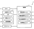
- FIG. 1 is a block diagram showing an electrical configuration of the road surface display device.
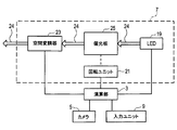
- FIG. 2 is an explanatory diagram illustrating the configuration of the light projection unit.
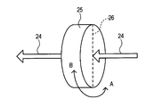
- FIG. 3 is an explanatory diagram showing the configuration of the polarizing plate.
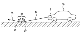
- FIG. 4 is an explanatory diagram illustrating an optical path of light projected by the light projection unit.
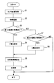
- FIG. 5 is a flowchart showing processing executed by the road surface display device.
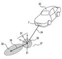
- FIG. 6 is an explanatory diagram showing the first area and the second area.
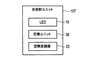
- FIG. 7 is a block diagram showing an electrical configuration of the light projection unit.
- FIG. 8 is a perspective view illustrating the configuration of the polarizing plate holder.
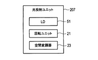
- FIG. 9 is a block diagram showing an electrical configuration of the light projection unit.
- FIG. 10 is an explanatory diagram illustrating the configuration of the light projection unit.
- FIG. 11 is an explanatory diagram showing the configuration of the 1 / 2 ⁇ plate.
- FIG. 12 is a block diagram illustrating an electrical configuration of the light projection unit.
- FIG. 13 is an explanatory diagram illustrating the configuration of the light projection unit.
- FIG. 14 is a perspective view showing the configuration of the 1 ⁇ 2 ⁇ plate holder.
- the road surface display device 1 is an in-vehicle device mounted on a vehicle.
- the vehicle on which the road surface display device 1 is mounted is referred to as the own vehicle.
- the road surface display device 1 includes a calculation unit 3, a camera 5, a light projection unit 7, and an input unit 9.
- the calculation unit 3 is a known computer including a CPU, RAM, ROM, and the like.
- the calculation unit 3 executes processing to be described later using a program stored in the ROM.
- the calculation unit 3 controls each unit of the road surface display device 1.
- the calculation unit 3 functionally includes a polarization control unit 11, a target position detection unit 13, a display image acquisition unit 15, and a light source control unit 17. The function of each unit will be described later.
- the camera 5 is attached near the front end of the host vehicle, and captures the scenery in front of the host vehicle and creates image data.
- the created image data is sent to the calculation unit 3.
- the light projection unit 7 projects light toward the road surface ahead of the host vehicle, and displays the light on the road surface.
- the light projection unit 7 includes an LED (light emitting diode) 19 that is a light source, a rotation unit 21, and a spatial modulator 23 as an electrical configuration.
- the LED 19 emits visible light.
- the rotation unit 21 sets the ratio of P-polarized light and S-polarized light (hereinafter referred to as P / S ratio) in the light emitted from the LED 19 together with the polarizing plate 25 described later. Details will be described later.
- the LED 19 is an example of a circularly polarized light source. Instead of the LED 19, another circularly polarized light source may be used. Other circularly polarized light sources include, for example, halogen lamps, HIDs (high intensity discharge lamps), and the like.
- the polarizing plate 25 for example, there is a type in which a minute slit is provided in a film and only polarized light parallel to the slit is allowed to pass.
- the polarizing plate 25 can convert light that is not linearly polarized light (for example, circularly polarized light like a laser) into linearly polarized light.
- the angle of the polarization plane depends on the angle of the polarizing plate 25.
- a 1 ⁇ 4 ⁇ plate is used, it is preferably used in combination with a light source such as an LED or HID.
- the spatial modulator 23 is a well-known digital mirror device (DMD).
- DMD digital mirror device
- the spatial modulator 23 spatially modulates the light emitted from the LED 19 to generate light that represents an image such as a character or a graphic.
- the input unit 9 is provided in the passenger compartment of the host vehicle, and accepts driver input operations. Examples of the input operation include start and end of road surface display, selection of an image to be displayed on the road surface, and setting by manually inputting a P / S ratio.
- the light projection unit 7 includes a polarizing plate 25.
- the light 24 emitted from the LED 19 passes through the polarizing plate 25, is spatially modulated by the spatial modulator 23, and then is projected toward the road surface. That is, the polarizing plate 25 and the spatial modulator 23 are on the optical axis of the light 24.
- the rotating unit 21 can rotate the polarizing plate 25 in the A direction or the B direction to change the angle of the polarizing plate 25.
- the direction of this rotation is a direction in which the inclination of the optical axis 26 of the polarizing plate 25 changes with respect to the polarization direction of the light 24 incident on the polarizing plate 25.
- the P / S ratio in the light 24 transmitted through the polarizing plate 25 varies depending on the angle of the polarizing plate 25. That is, depending on the angle of the polarizing plate 25, the P / S ratio in the light 24 transmitted through the polarizing plate 25 is a ratio that is substantially only P-polarized light or a ratio that is substantially only S-polarized light. .
- the P-polarized light is polarized light having a polarization plane in a direction perpendicular to the road surface when the road surface 27 (see FIG. 4) on which the light 24 projected by the light projection unit 7 is projected is used as an incident surface.
- the S-polarized light is polarized light having a polarization plane perpendicular to the P-polarized light.
- the rotation unit 21 is controlled by the polarization control unit 11 of the calculation unit 3. Therefore, the polarization control unit 11 controls the rotation unit 21 so that the P / S ratio in the light 24 transmitted through the polarizing plate 25 (that is, the light 24 incident on the road surface 27) is substantially only P-polarized light. It can be set to a certain ratio, or can be set to a ratio that is substantially only S-polarized light.
- step 1 the target position detection unit 13 acquires an image of the front of the host vehicle using the camera 5.
- step 2 the target position detection unit 13 executes processing for recognizing the target in the image acquired in step 1 by a known image recognition technique.
- the target that is the recognition target is, for example, a pedestrian, a bicycle, another vehicle, or the like.
- the target position detection unit 13 detects the position of the target recognized in step 2, and further determines whether or not the position of the target is within the first region 29.
- the first region 29 is a region on the road surface 27 in front of the host vehicle 30, and the distance from the incident point 31 where the light 24 enters the road surface 27 is a predetermined value. It is an area that is within.
- the position of the target can be detected based on the coordinates of the target in the vertical and horizontal directions in the image. Further, the position of the target may be detected using means such as a millimeter wave radar.
- step 4 When the position of the target is within the first area 29, the process proceeds to step 4; otherwise (when the position of the target is outside the first area 29 or when the target is not recognized). Goes to step 7.
- step 4 the polarization control unit 11 sets the P / S ratio in the light 24 incident on the road surface 27 to a ratio that is substantially only P-polarized light.
- step 5 the display image acquisition unit 15 outputs information on an image to be displayed by the light 24 to the spatial modulator 23.
- step 6 the light source control unit 17 turns on the LED 19 and projects light from the light projection unit 7 toward the road surface.
- the light projected on the road surface displays the image output to the spatial modulator 23 in step 5 described above.
- the P / S ratio in the light to be projected is a ratio that is substantially only P-polarized light when the process of step 4 is executed, and substantially S-polarized light when the process of step 8 described later is executed. The ratio is only.
- step 7 the target position detection unit 13 detects the position of the target recognized in step 2, and further determines whether or not the target position is within the second region 33.
- the second region 33 is a region on the road surface 27 and a region along the reflected light 35 in which the light 24 is reflected by the road surface 27.
- step 8 the polarization control unit 11 sets the P / S ratio in the light 24 incident on the road surface 27 to a ratio that is substantially only S-polarized light.
- the input unit 9 has a function of accepting an input of a P / S ratio by a user.
- the polarization control unit 11 sets the P / S ratio in the light 24 so as to match the input P / S ratio.
- the road surface display device 1 can set the P / S ratio in the light 24.
- the P / S ratio in the light 24 is set to a ratio that is substantially only P-polarized light
- the light 24 is mainly scattered and reflected to generate scattered light 37 as shown in FIG.
- the scattered light 37 is light that is easy to see for a target in the first region 29 close to the incident point 31. Therefore, the road surface display device 1 can perform display that is easy to see for the target in the first region 29 by setting the P / S ratio in the light 24 to a ratio that is substantially only P-polarized light.
- the road surface display device 1 can perform display that is easy to see for the target in the second region 33 by setting the P / S ratio in the light 24 to a ratio that is substantially only S-polarized light.
- the road surface display device 1 detects the position of the target and sets the P / S ratio according to the position of the target. Thereby, it is possible to perform easy-to-see display according to the position of the target.
- the road surface display device 1 includes an LED 19 as a light source, and sets a P / S ratio using a polarizing plate 25. As a result, the P / S ratio can be set with a simple configuration.
- the road surface display device 1 sets the P / S ratio by rotating the polarizing plate 25. As a result, the P / S ratio can be set with a simple configuration.
- the road surface display device 1 can project light that represents an image (for example, a character or a graphic) onto the road surface and display the image on the road surface.
- an image for example, a character or a graphic
- the light projection unit 107 includes an exchange unit 39.
- the light projection unit 107 includes a polarizing plate holder 40 shown in FIG.
- the polarizing plate holder 40 includes two polarizing plates 41 and 43 and a frame 45 that holds them.
- the optical axis 47 of the polarizing plate 41 and the optical axis 49 of the polarizing plate 43 are shifted by 90 degrees.
- the P / S ratio of the light 24 transmitted through the polarizing plate 41 is substantially a ratio of only P-polarized light.
- the P / S ratio of the light 24 transmitted through the polarizing plate 43 is a ratio that is substantially only S-polarized light.
- the polarizing plates 41 and 43 are an example of a group of polarizing plates having different optical axis directions.
- the exchange unit 39 can slide the polarizing plate holder 40 in the C direction or the D direction in FIG.
- the polarizing plate 43 is on the optical axis of the light 24, and the polarizing plate 41 is off the optical axis of the light 24.
- the P / S ratio of the light 24 transmitted through the polarizing plate 43 is substantially a ratio of only S-polarized light.
- the exchange unit 39 slides the polarizing plate holder 40 in the D direction, the polarizing plate 41 is on the optical axis of the light 24 and the polarizing plate 43 is off the optical axis of the light 24.
- the P / S ratio of the light 24 transmitted through the polarizing plate 41 is substantially a ratio of only P-polarized light. That is, the exchange unit 39 can select a polarizing plate located on the optical axis of the light 24 from the polarizing plates 41 and 43.
- the exchange unit 39 is controlled by the polarization control unit 11 of the calculation unit 3. Therefore, the polarization control unit 11 controls the exchange unit 39 and slides the polarizing plate holder 40 in the C direction or the D direction, so that the P / S ratio in the light 24 incident on the road surface 27 is substantially equal to P. It can be set to a ratio that is only polarized light, or can be set to a ratio that is substantially only S-polarized light.
- the road surface display device 1 sets the P / S ratio by selecting a polarizing plate located on the optical axis of the light 24 from the polarizing plates 41 and 43 having different optical axes. As a result, the P / S ratio can be set with a simple configuration.
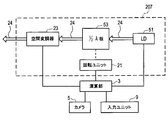
- the light projection unit 207 includes an LD (laser diode) 51 as a light source.
- the light projection unit 207 includes a 1 ⁇ 2 ⁇ plate 53 on the optical axis of the light 24.
- the light 24 emitted from the LD 51 passes through the 1 ⁇ 2 ⁇ plate 53, is spatially modulated by the spatial modulator 23, and then is projected toward the road surface.
- the LD 51 is an example of a linearly polarized light source.
- a light source other than the LD 51 may be used as a linearly polarized light source.
- the 1 ⁇ 2 ⁇ plate 53 is a plate made of a material that generates birefringence such as quartz or mica, and the birefringence component causes a phase delay of half the wavelength of the light emitted by the LD 51. It is a plate whose thickness is adjusted.
- the 1 / 2 ⁇ plate 53 can change the polarization angle of linearly polarized light.
- the rotation unit 21 can rotate the 1 ⁇ 2 ⁇ plate 53 in the A direction or the B direction to change the angle of the 1 ⁇ 2 ⁇ plate 53.
- the direction of this rotation is a direction in which the inclination of the optical axis 55 of the 1 / 2 ⁇ plate 53 changes with respect to the polarization direction of the light 24 incident on the 1 / 2 ⁇ plate 53.
- the P / S ratio in the light 24 transmitted through the 1 / 2 ⁇ plate 53 changes. That is, depending on the angle of the 1 ⁇ 2 ⁇ plate 53, the P / S ratio in the light 24 transmitted through the 1 ⁇ 2 ⁇ plate 53 is also a ratio that is substantially only P-polarized light, or is substantially only S-polarized light. It also becomes a ratio.
- the rotation unit 21 is controlled by the polarization control unit 11 of the calculation unit 3. Therefore, the polarization control unit 11 controls the rotation unit 21 to substantially change the P / S ratio in the light 24 transmitted through the 1 ⁇ 2 ⁇ plate 53 (that is, the light 24 incident on the road surface 27) to P polarization. It is also possible to set a ratio that is only S-polarized light, or a ratio that is substantially only S-polarized light.
- the road surface display device 1 includes an LD 51 as a light source, and sets a P / S ratio using a 1 / 2 ⁇ plate 53. As a result, the P / S ratio can be set with a simple configuration.
- the road surface display device 1 sets the P / S ratio by rotating the 1 ⁇ 2 ⁇ plate 53. As a result, the P / S ratio can be set with a simple configuration.
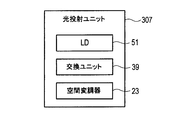
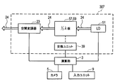
- the light projection unit 307 includes an LD 51 as a light source and an exchange unit 39. As shown in FIG. 13, the light projection unit 307 includes 1 ⁇ 2 ⁇ plates 57 and 59. The light 24 emitted from the LD 51 passes through one of the 1 ⁇ 2 ⁇ plates 57 and 59, is spatially modulated by the spatial modulator 23, and then is projected toward the road surface.
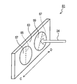
- the light projection unit 307 includes a 1 / 2 ⁇ plate holder 61 shown in FIG.
- the 1 / 2 ⁇ plate holder 61 includes two 1 / 2 ⁇ plates 57 and 59 and a frame 63 for holding them.
- the optical axis 65 of the 1 ⁇ 2 ⁇ plate 57 and the optical axis 67 of the 1 ⁇ 2 ⁇ plate 59 are shifted by 45 degrees.
- the P / S ratio of the light 24 transmitted through the 1 ⁇ 2 ⁇ plate 57 is substantially a ratio of only P-polarized light.
- the P / S ratio of the light 24 transmitted through the 1 ⁇ 2 ⁇ plate 59 is a ratio that is substantially only S-polarized light.
- the 1 / 2 ⁇ plates 57 and 59 are an example of a group of 1 / 2 ⁇ plates having different optical axis directions.
- the exchange unit 39 can slide the 1 / 2 ⁇ plate holder 61 in the C direction or the D direction in FIG.
- the 1 / 2 ⁇ plate holder 61 slides the 1 / 2 ⁇ plate holder 61 in the C direction
- the 1 / 2 ⁇ plate 59 is on the optical axis of the light 24 and the 1 / 2 ⁇ plate 57 is off the optical axis of the light 24.
- the P / S ratio of the light 24 transmitted through the 1 ⁇ 2 ⁇ plate 59 is substantially a ratio of only S-polarized light.
- the exchange unit 39 slides the 1 / 2 ⁇ plate holder 61 in the D direction, the 1 / 2 ⁇ plate 57 is on the optical axis of the light 24 and the 1 / 2 ⁇ plate 59 is off the optical axis of the light 24. .
- the P / S ratio of the light 24 transmitted through the 1 / 2 ⁇ plate 57 is substantially a ratio of only P-polarized light. That is, the exchange unit 39 can select a 1 / 2 ⁇ plate located on the optical axis of the light 24 from the 1 / 2 ⁇ plates 57 and 59.
- the exchange unit 39 is controlled by the polarization control unit 11 of the calculation unit 3. Therefore, the polarization control unit 11 controls the exchange unit 39 and slides the 1 ⁇ 2 ⁇ plate holder 61 in the C direction or the D direction, thereby substantially reducing the P / S ratio in the light 24 incident on the road surface 27. It is also possible to set a ratio that is only P-polarized light, or a ratio that is substantially only S-polarized light.
- the road surface display device 1 includes an LD 51 as a light source, and sets the P / S ratio using the 1 / 2 ⁇ plates 57 and 59. As a result, the P / S ratio can be set with a simple configuration.
- the road surface display device 1 selects the 1 ⁇ 2 ⁇ plate located on the optical axis of the light 24 from the 1 ⁇ 2 ⁇ plates 57 and 59 having different optical axis directions, whereby the P / S ratio is selected. Set. As a result, the P / S ratio can be set with a simple configuration. ⁇ Other embodiments> As mentioned above, although embodiment was illustrated, embodiment can take a various form, without being limited to the said embodiment.
- the P / S ratio set by the polarization control unit 11 may substantially include both P-polarized light and S-polarized light.
- the P / S ratio is set to a ratio that includes 80% P-polarized light and 20% S-polarized light, and in step 8, the ratio includes 20% P-polarized light and 80% S-polarized light. May be set.
- the light projected on the road surface does not display images such as characters and figures (for example, light having uniform illuminance and color regardless of position). Also good.
- the polarizing plate holder 40 may hold three or more polarizing plates. In this case, by sliding the polarizing plate holder 40, one polarizing plate located on the optical axis of the light 24 can be selected from the group of three or more polarizing plates.
- the 1 / 2 ⁇ plate holder 61 may hold three or more 1 / 2 ⁇ plates. In this case, by sliding the 1 / 2 ⁇ plate holder 61, one 1 / 2 ⁇ plate located on the optical axis of the light 24 is selected from the group of three or more 1 / 2 ⁇ plates. Can do.
- a liquid crystal panel, a galvano scanner, or the like may be used as the spatial modulator 23 instead of the DMD.
- the exchange unit 39 may select one polarizing plate located on the optical axis of the light 24 by rotating the polarizing plate holder 40.
- the exchange unit 39 may select one 1 ⁇ 2 ⁇ plate positioned on the optical axis of the light 24 by rotating the 1 ⁇ 2 ⁇ plate holder 61. .
- the setting method of the first region 29 and the second region 33 can be appropriately selected.
- the first area 29 can be set as in the first embodiment, and all other areas can be set as the second area 33.
- the second area 33 can be set as in the first embodiment, and all other areas can be set as the first area 29.
- the processing when a negative determination is made in step 7 may be other.
- the display may be performed.
- the P / S ratio of the light 24 can be set as appropriate.
- it may be a ratio that is substantially only P-polarized light, a ratio that is substantially only S-polarized light, or an intermediate ratio between them.
- the functions of one component in the above embodiment may be distributed as a plurality of components, or the functions of a plurality of components may be integrated into one component. Further, at least a part of the configuration of the above embodiment may be replaced with a configuration having the same function. Moreover, you may abbreviate
Landscapes
- Engineering & Computer Science (AREA)
- Physics & Mathematics (AREA)
- Multimedia (AREA)
- Signal Processing (AREA)
- General Physics & Mathematics (AREA)
- Mechanical Engineering (AREA)
- Geometry (AREA)
- Lighting Device Outwards From Vehicle And Optical Signal (AREA)
- Optics & Photonics (AREA)
Abstract
視認性が高い表示を行うことができる路面表示装置を提供する。路面表示装置は、路面に向けて光(24)を投射し、前記路面上で前記光による表示を行う光投射ユニット(7、107、207、307)と、前記光におけるP偏光及びS偏光の比率を設定する偏光制御ユニット(11)と、を備える。路面表示装置は、物標の位置を検出する物標位置検出ユニット(13)を備え、前記偏光制御ユニットは、前記物標の位置に応じて前記比率を設定してもよい。
Description
本出願は、2015年4月24日に出願された日本国特許出願2015-89407号に基づくものであり、その開示をここに参照により援用する。
本開示は路面表示装置に関する。
特定周波数の可視光を反射する光学物体を路面に設け、その光学物体に向けて、車両に搭載された進路予測装置から特定周波数の可視光を投射し、表示を行う技術が知られている(特許文献1参照)。
特許文献1記載の技術では、光学物体から、車両外に存在する歩行者等に到来する光の光量が十分ではなく、歩行者等は表示を視認しにくかった。
こうした点をかんがみて、本開示の目的の一つは、視認性が高い表示を行うことができる路面表示装置を提供することにある。
本開示の一例に係る路面表示装置は、路面に向けて光を投射し、路面上で光による表示を行う光投射ユニットと、光におけるP偏光及びS偏光の比率を設定する偏光制御ユニットとを備える。路面表示装置は、光におけるP偏光及びS偏光の比率を設定することができる。そのことにより、歩行者等にとって表示の視認性が向上する。
本開示についての上記および他の目的、特徴や利点は、添付図面を参照した下記詳細な説明から、より明確になる。添付図面において、
図1は、路面表示装置の電気的な構成を表すブロック図である。
図2は、光投射ユニットの構成を表す説明図である。
図3は、偏光板の構成を表す説明図である。
図4は、光投射ユニットにより投射された光の光路を表す説明図である。
図5は、路面表示装置が実行する処理を表すフローチャートである。
図6は、第1の領域及び第2の領域を表す説明図である。
図7は、光投射ユニットの電気的な構成を表すブロック図である。
図8は、偏光板保持体の構成を表す斜視図である。
図9は、光投射ユニットの電気的な構成を表すブロック図である。
図10は、光投射ユニットの構成を表す説明図である。
図11は、1/2λ板の構成を表す説明図である。
図12は、光投射ユニットの電気的な構成を表すブロック図である。
図13は、光投射ユニットの構成を表す説明図である。
図14は、1/2λ板保持体の構成を表す斜視図である。
実施形態を図面に基づき説明する。
<第1の実施形態>
1.路面表示装置1の構成
路面表示装置1の電気的な構成を図1に基づき説明する。路面表示装置1は車両に搭載される車載装置である。以下では、路面表示装置1を搭載する車両を自車両とする。路面表示装置1は、演算部3、カメラ5、光投射ユニット7、及び入力ユニット9を備える。
<第1の実施形態>
1.路面表示装置1の構成
路面表示装置1の電気的な構成を図1に基づき説明する。路面表示装置1は車両に搭載される車載装置である。以下では、路面表示装置1を搭載する車両を自車両とする。路面表示装置1は、演算部3、カメラ5、光投射ユニット7、及び入力ユニット9を備える。
演算部3はCPU、RAM、ROM等を備える公知のコンピュータである。演算部3は、ROMに記憶されたプログラムにより後述する処理を実行する。演算部3は、路面表示装置1の各部を制御する。演算部3は、機能的に、偏光制御ユニット11、物標位置検出ユニット13、表示画像取得ユニット15、及び光源制御ユニット17を備える。各ユニットの機能は後述する。
カメラ5は自車両の前端付近に取り付けられており、自車両の前方の風景を撮影し、画像データを作成する。作成した画像データは演算部3に送られる。
光投射ユニット7は、自車両前方の路面に向けて光を投射し、路面上で光による表示を行う。光投射ユニット7は、電気的な構成として、光源であるLED(発光ダイオード)19、回転ユニット21、及び空間変調器23を備える。LED19は可視光を発する。
回転ユニット21は、後述する偏光板25とともに、LED19が発する光におけるP偏 光及びS偏光の比率(以下ではP/S比率とする)を設定する。詳しくは後述する。
LED19は、円偏光の光源の一例である。LED19の代わりに、他の円偏光の光源を用いてもよい。他の円偏光の光源として、例えば、ハロゲンランプ、HID(高輝度放電ランプ)等がある。
偏光板25としては、例えば、フィルムに微小なスリットが設けられており、スリットと平行な偏光のみを通過させる方式のものがある。偏光板25は、直線偏光ではない光(例えばレーザーのような円偏光の光)を直線偏光に変換することができる。偏光面の角度(P/S比率)は、偏光板25の角度に依存する。また、偏光板25として、水晶や雲母等、複屈折を生じる材料で、複屈折光の位相が1/4λ遅れる厚さに調整された、1/4λ板等を用いることもできる。1/4λ板を使用する場合は、LEDやHID等の光源と組み合わせて使用することが好ましい。
空間変調器23は、周知のデジタルミラーデバイス(DMD)である。空間変調器23は、LED19が発する光を空間変調し、文字や図形等の画像を表現する光とする。
入力ユニット9は、自車両の車室内に設けられ、ドライバの入力操作を受け付ける。入力操作としては、路面表示の開始や終了、路面に表示する画像の選択、P/S比率の手動入力による設定等が挙げられる。
次に、図2~図4に基づき、光投射ユニット7をさらに詳細に説明する。図2に示すように、光投射ユニット7は、偏光板25を備える。LED19が発する光24は、偏光板25を通り、空間変調器23により空間変調されてから、路面に向けて投射される。すなわち、偏光板25及び空間変調器23は光24の光軸上にある。
回転ユニット21は、図3に示すように、偏光板25をA方向又はB方向に回転させ、偏光板25の角度を変化させることができる。この回転の方向は、偏光板25に入射する光24の偏光方位に対し、偏光板25の光学軸26の傾きが変化する方向である。
偏光板25の角度により、偏光板25を透過した光24におけるP/S比率は変化する。すなわち、偏光板25の角度により、偏光板25を透過した光24におけるP/S比率は、実質的にP偏光のみである比率にもなるし、実質的にS偏光のみである比率にもなる。
なお、上記のP偏光とは、光投射ユニット7が投射した光24が投射される路面27(図4参照)を入射面としたとき、路面に垂直な方向の偏光面を持つ偏光である。また、上記のS偏光とは、P偏光に垂直な偏光面を持つ偏光である。
回転ユニット21は、演算部3の偏光制御ユニット11により制御される。よって、偏光制御ユニット11は、回転ユニット21を制御することで、偏光板25を透過した光24(すなわち、路面27に入射する光24)におけるP/S比率を、実質的にP偏光のみである比率に設定することもできるし、実質的にS偏光のみである比率に設定することもできる。
2.路面表示装置1が実行する処理
路面表示装置1(特に演算部3)が実行する処理を図5、図6に基づき説明する。この処理は、路面表示の開始を指示する入力を入力ユニット9が受け付けたときに実行される。
路面表示装置1(特に演算部3)が実行する処理を図5、図6に基づき説明する。この処理は、路面表示の開始を指示する入力を入力ユニット9が受け付けたときに実行される。
ステップ1では、物標位置検出ユニット13が、カメラ5を用いて自車両の前方を撮影した画像を取得する。
ステップ2では、物標位置検出ユニット13が、前記ステップ1で取得した画像において、周知の画像認識技術により、物標を認識する処理を実行する。認識対象である物標は、例えば、歩行者、自転車、他の車両等である。
ステップ3では、物標位置検出ユニット13が、前記ステップ2において認識した物標の位置を検出し、さらに、その物標の位置が第1の領域29内であるか否かを判断する。ここで、第1の領域29とは、図6に示すように、自車両30の前方における路面27上の領域であって、光24が路面27に入射する入射点31からの距離が所定値以内である領域である。物標の位置は、画像内における縦方向及び横方向での物標の座標に基づき検出することができる。また、ミリ波レーダ等の手段を用いて物標の位置を検出してもよい。
物標の位置が第1の領域29内である場合はステップ4に進み、それ以外の場合(物標の位置が第1の領域29外である場合、又は物標を認識しなかった場合)はステップ7に進む。
ステップ4では、偏光制御ユニット11が、路面27に入射する光24におけるP/S比率を、実質的にP偏光のみである比率に設定する。
ステップ5では、表示画像取得ユニット15が、光24により表示する画像の情報を空間変調器23に出力する。
ステップ6では、光源制御ユニット17がLED19をオンの状態にし、光投射ユニット7から路面に向けて光を投射する。路面に投射される光は、前記ステップ5で空間変調器23に出力した画像を表示する。投射する光におけるP/S比率は、前記ステップ4の処理を実行した場合は、実質的にP偏光のみである比率であり、後述するステップ8の処理を実行した場合は、実質的にS偏光のみである比率である。
一方、前記ステップ3で否定判断した場合はステップ7に進む。ステップ7では、物標位置検出ユニット13が、前記ステップ2において認識した物標の位置を検出し、さらに、その物標の位置が第2の領域33内であるか否かを判断する。
ここで、第2の領域33とは、図6に示すように、路面27上の領域であって、光24が路面27で反射した反射光35に沿った領域である。物標の位置が第2の領域33内である場合はステップ8に進み、それ以外の場合(物標の位置が第2の領域33外である場合、又は物標を認識しなかった場合)は本処理を終了する。
ステップ8では、偏光制御ユニット11が、路面27に入射する光24におけるP/S比率を、実質的にS偏光のみである比率に設定する。
3.手動によるP/S比率の設定
入力ユニット9は、ユーザによるP/S比率の入力を受け付ける機能を有する。入力ユニット9にP/S比率が入力されたとき、偏光制御ユニット11は、その入力されたP/S比率と一致するように、光24におけるP/S比率を設定する。
入力ユニット9は、ユーザによるP/S比率の入力を受け付ける機能を有する。入力ユニット9にP/S比率が入力されたとき、偏光制御ユニット11は、その入力されたP/S比率と一致するように、光24におけるP/S比率を設定する。
4.路面表示装置1が奏する効果
(1A)路面表示装置1は光24におけるP/S比率を設定することができる。光24におけるP/S比率を、実質的にP偏光のみである比率に設定した場合、図6に示すように、光24は、主として散乱反射し、散乱光37を生じさせる。散乱光37は、入射点31に近い第1の領域29にある物標にとって見やすい光である。よって、路面表示装置1は、光24におけるP/S比率を、実質的にP偏光のみである比率に設定することで、第1の領域29にある物標にとって見やすい表示を行うことができる。
(1A)路面表示装置1は光24におけるP/S比率を設定することができる。光24におけるP/S比率を、実質的にP偏光のみである比率に設定した場合、図6に示すように、光24は、主として散乱反射し、散乱光37を生じさせる。散乱光37は、入射点31に近い第1の領域29にある物標にとって見やすい光である。よって、路面表示装置1は、光24におけるP/S比率を、実質的にP偏光のみである比率に設定することで、第1の領域29にある物標にとって見やすい表示を行うことができる。
また、光24におけるP/S比率を、実質的にS偏光のみである比率に設定した場合、図6に示すように、光24は、主として直接反射し、反射光35を生じさせる。反射光35は、それに沿っている第2の領域33にある物標にとって見やすい光である。よって、路面表示装置1は、光24におけるP/S比率を、実質的にS偏光のみである比率に設定することで、第2の領域33にある物標にとって見やすい表示を行うことができる。
(1B)路面表示装置1は、物標の位置を検出し、その物標の位置に応じてP/S比率を設定する。そのことにより、物標の位置に応じて見やすい表示を行うことができる。
(1C)路面表示装置1は、光源としてLED19を備え、偏光板25を用いてP/S比率を設定する。そのことにより、簡易な構成でP/S比率を設定することができる。
(1D)路面表示装置1は、偏光板25を回転させることで、P/S比率を設定する。そのことにより、簡易な構成でP/S比率を設定することができる。
(1E)路面表示装置1は、画像(例えば文字や図形等)を表現する光を路面に投射し、その画像を路面上で表示することができる。
<第2の実施形態>
1.第1の実施形態との相違点
第2の実施形態は、基本的な構成は前記第1の実施形態と同様であるため、共通する構成については説明を省略し、相違点を中心に説明する。
<第2の実施形態>
1.第1の実施形態との相違点
第2の実施形態は、基本的な構成は前記第1の実施形態と同様であるため、共通する構成については説明を省略し、相違点を中心に説明する。
図7に示すように、光投射ユニット107は、交換ユニット39を備える。また、光投射ユニット107は、図8に示す、偏光板保持体40を備える。偏光板保持体40は、2枚の偏光板41、43と、それらを保持する枠45とを備える。偏光板41の光学軸47と、偏光板43の光学軸49とは、90度ずれている。偏光板41を透過した光24のP/S比率は、実質的にP偏光のみである比率になる。また、偏光板43を透過した光24のP/S比率は、実質的にS偏光のみである比率になる。なお、偏光板41、43は、光学軸の向きが互いに異なる偏光板の群の一例である。
交換ユニット39は、偏光板保持体40を、図8におけるC方向又はD方向にスライドさせることができる。交換ユニット39が偏光板保持体40をC方向にスライドさせたとき、偏光板43は光24の光軸上にあり、偏光板41は光24の光軸から外れる。このとき、偏光板43を透過した光24のP/S比率は、実質的にS偏光のみである比率になる。
一方、交換ユニット39が偏光板保持体40をD方向にスライドさせたとき、偏光板41は光24の光軸上にあり、偏光板43は光24の光軸から外れる。このとき、偏光板41を透過した光24のP/S比率は、実質的にP偏光のみである比率になる。すなわち、交換ユニット39は、偏光板41、43の中から、光24の光軸上に位置する偏光板を選択することができる。
交換ユニット39は、演算部3の偏光制御ユニット11により制御される。よって、偏光制御ユニット11は、交換ユニット39を制御し、偏光板保持体40をC方向又はD方向にスライドさせることで、路面27に入射する光24におけるP/S比率を、実質的にP偏光のみである比率に設定することもできるし、実質的にS偏光のみである比率に設定することもできる。
2.路面表示装置1が奏する効果
以上詳述した第2の実施形態によれば、前述した第1の実施形態の効果(1A)~(1C)、(1E)に加え、以下の効果が得られる。
以上詳述した第2の実施形態によれば、前述した第1の実施形態の効果(1A)~(1C)、(1E)に加え、以下の効果が得られる。
(2A)路面表示装置1は、光学軸の向きが互いに異なる偏光板41、43の中から、光24の光軸上に位置する偏光板を選択することで、P/S比率を設定する。そのことにより、簡易な構成でP/S比率を設定することができる。
<第3の実施形態>
1.第1の実施形態との相違点
第3の実施形態は、基本的な構成は前記第1の実施形態と同様であるため、共通する構成については説明を省略し、相違点を中心に説明する。
<第3の実施形態>
1.第1の実施形態との相違点
第3の実施形態は、基本的な構成は前記第1の実施形態と同様であるため、共通する構成については説明を省略し、相違点を中心に説明する。
図9に示すように、光投射ユニット207は、光源としてLD(レーザダイオード)51を備える。また、図10に示すように、光投射ユニット207は、光24の光軸上に1/2λ板53を備える。LD51が発する光24は、1/2λ板53を通り、空間変調器23により空間変調されてから、路面に向けて投射される。LD51は直線偏光の光源の一例である。直線偏光の光源として、LD51以外のものを用いてもよい。
ここで、1/2λ板53とは、水晶や雲母等の複屈折を生じる材料から成る板であって、複屈折の成分がちょうどLD51が発する光の波長の半波長の位相遅れを生じさせるように厚さを調整された板である。1/2λ板53は、直線偏光の偏光角度を変えることが可能である。
回転ユニット21は、図11に示すように、1/2λ板53をA方向又はB方向に回転させ、1/2λ板53の角度を変化させることができる。この回転の方向は、1/2λ板53に入射する光24の偏光方位に対し、1/2λ板53の光学軸55の傾きが変化する方向である。
1/2λ板53の角度により、1/2λ板53を透過した光24におけるP/S比率は変化する。すなわち、1/2λ板53の角度により、1/2λ板53を透過した光24におけるP/S比率は、実質的にP偏光のみである比率にもなるし、実質的にS偏光のみである比率にもなる。
回転ユニット21は、演算部3の偏光制御ユニット11により制御される。よって、偏光制御ユニット11は、回転ユニット21を制御することで、1/2λ板53を透過した光24(すなわち、路面27に入射する光24)におけるP/S比率を、実質的にP偏光のみである比率に設定することもできるし、実質的にS偏光のみである比率に設定することもできる。
2.路面表示装置1が奏する効果
以上詳述した第3の実施形態によれば、前述した第1の実施形態の効果(1A)、(1B)、(1E)に加え、以下の効果が得られる。
以上詳述した第3の実施形態によれば、前述した第1の実施形態の効果(1A)、(1B)、(1E)に加え、以下の効果が得られる。
(3A)路面表示装置1は、光源としてLD51を備え、1/2λ板53を用いてP/S比率を設定する。そのことにより、簡易な構成でP/S比率を設定することができる。
(3B)路面表示装置1は、1/2λ板53を回転させることで、P/S比率を設定する。そのことにより、簡易な構成でP/S比率を設定することができる。
<第4の実施形態>
1.第1の実施形態との相違点
第4の実施形態は、基本的な構成は前記第1の実施形態と同様であるため、共通する構成については説明を省略し、相違点を中心に説明する。
<第4の実施形態>
1.第1の実施形態との相違点
第4の実施形態は、基本的な構成は前記第1の実施形態と同様であるため、共通する構成については説明を省略し、相違点を中心に説明する。
図12に示すように、光投射ユニット307は、光源としてのLD51と、交換ユニット39とを備える。また、図13に示すように、光投射ユニット307は、1/2λ板57、59を備える。LD51が発する光24は、1/2λ板57、59のうちの一方を通り、空間変調器23により空間変調されてから、路面に向けて投射される。
また、光投射ユニット307は、図14に示す、1/2λ板保持体61を備える。1/2λ板保持体61は、2枚の1/2λ板57、59と、それらを保持する枠63とを備える。1/2λ板57の光学軸65と、1/2λ板59の光学軸67とは、45度ずれている。1/2λ板57を透過した光24のP/S比率は、実質的にP偏光のみである比率になる。また、1/2λ板59を透過した光24のP/S比率は、実質的にS偏光のみである比率になる。なお、1/2λ板57、59は、光学軸の向きが互いに異なる1/2λ板の群の一例である。
交換ユニット39は、1/2λ板保持体61を、図14におけるC方向又はD方向にスライドさせることができる。交換ユニット39が1/2λ板保持体61をC方向にスライドさせたとき、1/2λ板59は光24の光軸上にあり、1/2λ板57は光24の光軸から外れる。このとき、1/2λ板59を透過した光24のP/S比率は、実質的にS偏光のみである比率になる。
一方、交換ユニット39が1/2λ板保持体61をD方向にスライドさせたとき、1/2λ板57は光24の光軸上にあり、1/2λ板59は光24の光軸から外れる。このとき、1/2λ板57を透過した光24のP/S比率は、実質的にP偏光のみである比率になる。すなわち、交換ユニット39は、1/2λ板57、59の中から、光24の光軸上に位置する1/2λ板を選択することができる。
交換ユニット39は、演算部3の偏光制御ユニット11により制御される。よって、偏光制御ユニット11は、交換ユニット39を制御し、1/2λ板保持体61をC方向又はD方向にスライドさせることで、路面27に入射する光24におけるP/S比率を、実質的にP偏光のみである比率に設定することもできるし、実質的にS偏光のみである比率に設定することもできる。
2.路面表示装置1が奏する効果
以上詳述した第4の実施形態によれば、前述した第1の実施形態の効果(1A)、(1B)、(1E)に加え、以下の効果が得られる。
以上詳述した第4の実施形態によれば、前述した第1の実施形態の効果(1A)、(1B)、(1E)に加え、以下の効果が得られる。
(4A)路面表示装置1は、光源としてLD51を備え、1/2λ板57、59を用いてP/S比率を設定する。そのことにより、簡易な構成でP/S比率を設定することができる。
(4B)路面表示装置1は、光学軸の向きが互いに異なる1/2λ板57、59の中から、光24の光軸上に位置する1/2λ板を選択することで、P/S比率を設定する。そのことにより、簡易な構成でP/S比率を設定することができる。
<その他の実施形態>
以上、実施形態を例示したが、実施形態は上記実施形態に限定されることなく、種々の形態を採り得る。
<その他の実施形態>
以上、実施形態を例示したが、実施形態は上記実施形態に限定されることなく、種々の形態を採り得る。
(1)前記第1~第4の実施形態において、偏光制御ユニット11が設定するP/S比率は、実質的にP偏光及びS偏光の両方を含むものであってもよい。例えば、前記ステップ4において、P/S比率を、P偏光を80%含むともにS偏光を20%含む比率に設定し、前記ステップ8において、P偏光を20%含むともにS偏光を80%含む比率に設定してもよい。
(2)前記第1~第4の実施形態において、路面に投射する光は、文字や図形等の画像を表示しないもの(例えば、位置によらず均一な照度及び色を有する光)であってもよい。
(3)前記第2の実施形態において、偏光板保持体40は、3枚以上の偏光板を保持していてもよい。この場合、偏光板保持体40をスライドさせることで、3枚以上の偏光板の群の中から、光24の光軸上に位置する1枚の偏光板を選択することができる。
また、前記第4の実施形態において、1/2λ板保持体61は、3枚以上の1/2λ板を保持していてもよい。この場合、1/2λ板保持体61をスライドさせることで、3枚以上の1/2λ板の群の中から、光24の光軸上に位置する1枚の1/2λ板を選択することができる。
(4)前記第1~第4の実施形態において、空間変調器23として、DMDの代わりに、液晶パネルやガルバノスキャナ等を用いてもよい。
(5)前記第2の実施形態において、交換ユニット39は、偏光板保持体40を回転させることで、光24の光軸上に位置する1枚の偏光板を選択してもよい。また、前記第4の実施形態において、交換ユニット39は、1/2λ板保持体61を回転させることで、光24の光軸上に位置する1枚の1/2λ板を選択してもよい。
(6)前記第1~第4の実施形態において、第1の領域29、第2の領域33の設定方法は適宜選択することができる。例えば、前記第1の実施形態のように第1の領域29を設定し、それ以外の領域を全て第2の領域33とすることができる。また、前記第1の実施形態のように第2の領域33を設定し、それ以外の領域を全て第1の領域29とすることができる。
(7)前記第1~第4の実施形態において、前記ステップ7で否定判断した場合の処理は他のものであってもよい。例えば、前記ステップ7で否定判断した場合も、表示を行ってもよい。その場合の光24のP/S比率は適宜設定することができる。例えば、実質的にP偏光のみである比率であってもよいし、実質的にS偏光のみである比率であってもよいし、それらの中間の比率であってもよい。
(8)上記実施形態における1つの構成要素が有する機能を複数の構成要素として分散させたり、複数の構成要素が有する機能を1つの構成要素に統合させたりしてもよい。また、上記実施形態の構成の少なくとも一部を、同様の機能を有する構成に置き換えてもよい。また、上記実施形態の構成の一部を省略してもよい。また、上記実施形態の構成の少なくとも一部を、他の上記実施形態の構成に対して付加又は置換してもよい。
(9)上述した路面表示装置の他、当該路面表示装置を構成要素とするシステム、当該路面表示装置の演算部としてコンピュータを機能させるためのプログラム、このプログラムを記録した媒体、路面表示方法等、の種々の形態も実施形態である。
Claims (7)
- 路面に向けて光(24)を投射し、前記路面上で前記光による表示を行う光投射ユニット(7、107、207、307)と、
前記光におけるP偏光及びS偏光の比率を設定する偏光制御ユニット(11)と、
を備える路面表示装置(1)。 - 請求項1に記載の路面表示装置であって、
物標の位置を検出する物標位置検出ユニット(13)を備え、
前記偏光制御ユニットは、前記物標の位置に応じて前記比率を設定する路面表示装置。 - 請求項1又は2に記載の路面表示装置であって、
前記光投射ユニットは前記光の光源として円偏光の光源(19)を備え、
前記偏光制御ユニットは、前記光の光軸上にある偏光板(25、41、43)を用いて前記比率を設定する路面表示装置。 - 請求項3に記載の路面表示装置であって、
前記偏光制御ユニットは、前記偏光板を回転させること、又は、光学軸の向きが互いに異なる偏光板の群の中から前記偏光板を選択することで、前記比率を設定する路面表示装置。 - 請求項1又は2に記載の路面表示装置であって、
前記光投射ユニットは前記光の光源として直線偏光の光源(51)を備え、
前記偏光制御ユニットは、前記光の光軸上にある1/2λ板(53、57、59)を用いて前記比率を設定する路面表示装置。 - 請求項5に記載の路面表示装置であって、
前記偏光制御ユニットは、前記1/2λ板を回転させること、又は、光学軸の向きが互いに異なる1/2λ板の群の中から前記1/2λ板を選択することで、前記比率を設定する路面表示装置。 - 請求項1~6のいずれか1項に記載の路面表示装置であって、
前記光投射ユニットは、画像を表現する前記光を投射する路面表示装置。
Priority Applications (1)
| Application Number | Priority Date | Filing Date | Title |
|---|---|---|---|
| US15/567,854 US20180120686A1 (en) | 2015-04-24 | 2016-03-28 | Road surface displaying device |
Applications Claiming Priority (2)
| Application Number | Priority Date | Filing Date | Title |
|---|---|---|---|
| JP2015-089407 | 2015-04-24 | ||
| JP2015089407A JP6350378B2 (ja) | 2015-04-24 | 2015-04-24 | 路面表示装置 |
Publications (1)
| Publication Number | Publication Date |
|---|---|
| WO2016170737A1 true WO2016170737A1 (ja) | 2016-10-27 |
Family
ID=57142999
Family Applications (1)
| Application Number | Title | Priority Date | Filing Date |
|---|---|---|---|
| PCT/JP2016/001786 Ceased WO2016170737A1 (ja) | 2015-04-24 | 2016-03-28 | 路面表示装置 |
Country Status (3)
| Country | Link |
|---|---|
| US (1) | US20180120686A1 (ja) |
| JP (1) | JP6350378B2 (ja) |
| WO (1) | WO2016170737A1 (ja) |
Cited By (2)
| Publication number | Priority date | Publication date | Assignee | Title |
|---|---|---|---|---|
| CN108162957A (zh) * | 2017-12-21 | 2018-06-15 | 苏州视由谱光电科技有限公司 | 一种汽车投射图案系统及其投射方法 |
| EP3537032A1 (en) * | 2018-03-05 | 2019-09-11 | Stanley Electric Co., Ltd. | Lighting tool for vehicle |
Families Citing this family (3)
| Publication number | Priority date | Publication date | Assignee | Title |
|---|---|---|---|---|
| JP7442948B2 (ja) * | 2021-10-18 | 2024-03-05 | 矢崎総業株式会社 | 車外表示装置 |
| KR20230168859A (ko) * | 2022-06-08 | 2023-12-15 | 현대모비스 주식회사 | 자동차 조명 장치 및 그 작동 방법 |
| JP2025128920A (ja) * | 2024-02-22 | 2025-09-03 | マクセル株式会社 | 情報投射方法、および、情報投射装置 |
Citations (4)
| Publication number | Priority date | Publication date | Assignee | Title |
|---|---|---|---|---|
| JPH10122833A (ja) * | 1996-10-15 | 1998-05-15 | Asahi Optical Co Ltd | 表面測定装置 |
| JP2003231438A (ja) * | 2002-02-07 | 2003-08-19 | Toyota Motor Corp | 車両運転支援装置および車両運転支援システム |
| JP2005161977A (ja) * | 2003-12-02 | 2005-06-23 | Honda Motor Co Ltd | 車両用走行支援装置 |
| JP2014010089A (ja) * | 2012-06-29 | 2014-01-20 | Ricoh Co Ltd | 測距装置 |
-
2015
- 2015-04-24 JP JP2015089407A patent/JP6350378B2/ja not_active Expired - Fee Related
-
2016
- 2016-03-28 US US15/567,854 patent/US20180120686A1/en not_active Abandoned
- 2016-03-28 WO PCT/JP2016/001786 patent/WO2016170737A1/ja not_active Ceased
Patent Citations (4)
| Publication number | Priority date | Publication date | Assignee | Title |
|---|---|---|---|---|
| JPH10122833A (ja) * | 1996-10-15 | 1998-05-15 | Asahi Optical Co Ltd | 表面測定装置 |
| JP2003231438A (ja) * | 2002-02-07 | 2003-08-19 | Toyota Motor Corp | 車両運転支援装置および車両運転支援システム |
| JP2005161977A (ja) * | 2003-12-02 | 2005-06-23 | Honda Motor Co Ltd | 車両用走行支援装置 |
| JP2014010089A (ja) * | 2012-06-29 | 2014-01-20 | Ricoh Co Ltd | 測距装置 |
Cited By (3)
| Publication number | Priority date | Publication date | Assignee | Title |
|---|---|---|---|---|
| CN108162957A (zh) * | 2017-12-21 | 2018-06-15 | 苏州视由谱光电科技有限公司 | 一种汽车投射图案系统及其投射方法 |
| EP3537032A1 (en) * | 2018-03-05 | 2019-09-11 | Stanley Electric Co., Ltd. | Lighting tool for vehicle |
| US10697605B2 (en) | 2018-03-05 | 2020-06-30 | Stanley Electric Co., Ltd. | Lighting tool for vehicle |
Also Published As
| Publication number | Publication date |
|---|---|
| JP2016203856A (ja) | 2016-12-08 |
| JP6350378B2 (ja) | 2018-07-04 |
| US20180120686A1 (en) | 2018-05-03 |
Similar Documents
| Publication | Publication Date | Title |
|---|---|---|
| JP6350378B2 (ja) | 路面表示装置 | |
| JP2019200432A (ja) | 映像投射装置 | |
| CN104977785A (zh) | 组合式可见与不可见投影系统 | |
| KR102071155B1 (ko) | 차량용 표시 장치 및 차량용 표시 방법 | |
| JPWO2017094427A1 (ja) | ヘッドアップディスプレイ | |
| JP2008230364A (ja) | 前照灯制御装置 | |
| WO2016170966A1 (ja) | 光源装置、投射型表示装置および表示システム | |
| CN106232422A (zh) | 前照灯控制装置 | |
| US20190155563A1 (en) | Communication apparatus, display apparatus, control method thereof, storage medium, and display system for configuring multi-display settings | |
| US20150130717A1 (en) | Display apparatus, display system, and control method | |
| WO2016013167A1 (ja) | 車両用表示制御装置 | |
| US9841847B2 (en) | Projection device and projection method, for projecting a first image based on a position of a moving object and a second image without depending on the position | |
| JP4590858B2 (ja) | 書き込み可能プロジェクタおよび光ポインタ | |
| JP6766716B2 (ja) | 情報処理装置、画像表示プログラム、画像表示方法および表示システム | |
| US20150156447A1 (en) | Curved display apparatus for vehicle | |
| JP2013083985A (ja) | 投影装置、投影方法及びプログラム | |
| JP2015049272A (ja) | 投射型表示装置 | |
| JP6171502B2 (ja) | プロジェクタおよびプロジェクタ機能を有する電子機器 | |
| JP2013015632A (ja) | 偏光変換素子およびそれを用いた画像表示装置 | |
| JP2016164704A (ja) | 画像表示装置および画像表示システム | |
| US10712841B2 (en) | Display control device, display control system, display control method, and storage medium having stored thereon display control program | |
| JP2008216351A (ja) | 投影装置、投影方法及びプログラム | |
| US20250080702A1 (en) | Control device, control method, control program, and system | |
| JP7469174B2 (ja) | 表示装置及び表示方法 | |
| JP2014126640A (ja) | 車両用光源制御装置、及び車両用画像投影装置 |
Legal Events
| Date | Code | Title | Description |
|---|---|---|---|
| 121 | Ep: the epo has been informed by wipo that ep was designated in this application |
Ref document number: 16782765 Country of ref document: EP Kind code of ref document: A1 |
|
| WWE | Wipo information: entry into national phase |
Ref document number: 15567854 Country of ref document: US |
|
| NENP | Non-entry into the national phase |
Ref country code: DE |
|
| 122 | Ep: pct application non-entry in european phase |
Ref document number: 16782765 Country of ref document: EP Kind code of ref document: A1 |