WO2016167244A1 - 偏光光照射装置 - Google Patents
偏光光照射装置 Download PDFInfo
- Publication number
- WO2016167244A1 WO2016167244A1 PCT/JP2016/061791 JP2016061791W WO2016167244A1 WO 2016167244 A1 WO2016167244 A1 WO 2016167244A1 JP 2016061791 W JP2016061791 W JP 2016061791W WO 2016167244 A1 WO2016167244 A1 WO 2016167244A1
- Authority
- WO
- WIPO (PCT)
- Prior art keywords
- polarizer
- spring
- wall
- polarized light
- light irradiation
- Prior art date
- Legal status (The legal status is an assumption and is not a legal conclusion. Google has not performed a legal analysis and makes no representation as to the accuracy of the status listed.)
- Ceased
Links
Images





Classifications
-
- G—PHYSICS
- G02—OPTICS
- G02B—OPTICAL ELEMENTS, SYSTEMS OR APPARATUS
- G02B5/00—Optical elements other than lenses
- G02B5/30—Polarising elements
-
- G—PHYSICS
- G02—OPTICS
- G02F—OPTICAL DEVICES OR ARRANGEMENTS FOR THE CONTROL OF LIGHT BY MODIFICATION OF THE OPTICAL PROPERTIES OF THE MEDIA OF THE ELEMENTS INVOLVED THEREIN; NON-LINEAR OPTICS; FREQUENCY-CHANGING OF LIGHT; OPTICAL LOGIC ELEMENTS; OPTICAL ANALOGUE/DIGITAL CONVERTERS
- G02F1/00—Devices or arrangements for the control of the intensity, colour, phase, polarisation or direction of light arriving from an independent light source, e.g. switching, gating or modulating; Non-linear optics
- G02F1/01—Devices or arrangements for the control of the intensity, colour, phase, polarisation or direction of light arriving from an independent light source, e.g. switching, gating or modulating; Non-linear optics for the control of the intensity, phase, polarisation or colour
- G02F1/13—Devices or arrangements for the control of the intensity, colour, phase, polarisation or direction of light arriving from an independent light source, e.g. switching, gating or modulating; Non-linear optics for the control of the intensity, phase, polarisation or colour based on liquid crystals, e.g. single liquid crystal display cells
- G02F1/133—Constructional arrangements; Operation of liquid crystal cells; Circuit arrangements
- G02F1/1333—Constructional arrangements; Manufacturing methods
- G02F1/1337—Surface-induced orientation of the liquid crystal molecules, e.g. by alignment layers
Definitions
- the present invention relates to a polarized light irradiation apparatus.
- Patent Document 1 discloses a polarizing element unit that fixes a wire grid polarizing element by arranging a plurality of wire grid polarizing elements on a lower frame and covering the upper frame from above.
- a polarizer support member or frame formed of metal and a wire grid polarizing element formed of glass are deformed when the temperature rises to a certain temperature, for example, about 200 degrees. The amount is different.
- the wire grid polarizing element is sandwiched between the frames, and there is no gap between the wire grid polarizing element and the frame.
- a problem such as breakage of the wire grid polarizing element may occur due to a difference in dimensions due to thermal expansion between the wire grid polarizing element and the polarizer support member.
- the present invention has been made in view of such circumstances, and an object thereof is to provide a polarized light irradiation apparatus capable of preventing problems due to thermal expansion.
- a polarized light irradiation apparatus includes, for example, a light source, a plate-like polarizer having a substantially rectangular shape in a plan view that polarizes light emitted from the light source, and the polarizer.
- a holding member having a wall against which a side surface of the polarizer contacts, and an elastic member provided on the holding member and contacting the first side surface of the polarizer, the polarizer And an elastic member that urges a side surface facing the first side surface toward the wall.
- the elastic member abuts on the first side surface of the plate-like polarizer having a substantially rectangular shape in plan view that polarizes light from the light source.
- the elastic member biases the side surface facing the first side surface of the polarizer toward the wall of the holding member.
- the elastic member includes a first elastic member that contacts the first side surface of the polarizer, and a second elastic member that contacts the second side surface adjacent to the first side surface of the polarizer.
- the wall includes a first wall and a second wall that are two orthogonal walls, and the first elastic member is opposed to the first side surface of the polarizer.
- the second elastic member urges the side surface of the polarizer facing the second side surface toward the second side surface. May be. Thereby, the polarizer can be positioned with respect to the holding member on a plane orthogonal to the first side surface of the polarizer.
- the elastic member is a spring-loaded screw having a ball that contacts the polarizer, a spring that urges the ball toward the polarizer, and a screw portion in which the spring is provided.
- a thickness of the polarizer may be larger than a diameter of the screw portion.
- the elastic member may include two springs, and the two springs may respectively press the vicinity of both ends of the first side surface.
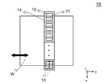
- FIG. 2 is a plan view illustrating an outline of a polarized light irradiation unit 10.
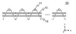
- FIG. 2 is a side view illustrating an outline of a polarized light irradiation unit 10.
- FIG. 2 is a plan view showing an outline of a polarizer unit 13.
- FIG. 3 is a cross-sectional view showing an outline of a polarizer unit 13.
- FIG. It is a figure which shows the outline of the conventional form which urges
- FIG. 1 is a front view showing an outline of a polarized light irradiation apparatus 1 according to the first embodiment.
- FIG. 2 is a side view showing an outline of the polarized light irradiation apparatus 1.
- the polarized light irradiation apparatus 1 obtains polarized light by passing light from a light source through a polarizing film, and irradiates the exposed surface of a glass substrate or the like to generate an alignment film or the like for a liquid crystal panel. It is.
- the transport direction of the object to be exposed W will be referred to as the y direction, the direction orthogonal to the transport direction as the x direction, and the vertical direction as the z direction.
- the polarized light irradiation device 1 mainly includes a polarized light irradiation unit 10, a drive unit 20, and an imaging unit 30.
- FIG. 2 is a plan view showing an outline of the polarized light irradiation unit 10.
- FIG. 3 is a side view showing an outline of the polarized light irradiation unit 10. Note that the two-dot chain line in FIG. 3 indicates a range in which light is irradiated.
- the polarized light irradiation unit 10 mainly includes a light source 11, a specific wavelength transmission filter 12, a polarizer unit 13, and a base member 14. In FIG. 2, the specific wavelength transmission filter 12 is not shown.
- the light source 11 is a rod-shaped lamp and emits unpolarized light (for example, ultraviolet light).
- a plurality of light sources are arranged side by side in the x direction so that the longitudinal direction is along the y direction. Note that the form of the light source 11 is not limited to this, and may be, for example, a single lamp that is long along the x direction.
- the specific wavelength transmission filter 12 is a filter that transmits only light in a specific wavelength range and absorbs light of other wavelengths.
- the specific wavelength transmission filter 12 is provided below the light source 11 ( ⁇ z side).
- the polarizer unit 13 is provided on the lower side ( ⁇ z side) of the specific wavelength transmission filter 12.
- the polarizer unit 13 includes, for example, a polarizer that polarizes unpolarized light emitted from the light source 11.
- the polarizer unit 13 is provided on the base member 14. The polarizer unit 13 will be described in detail later.
- One specific wavelength transmission filter 12 and one polarizer unit 13 are provided for each light source 11. Two specific wavelength transmission filters 12 and two polarizer units 13 may be provided for each light source 11. In this case, the specific wavelength transmission filter 12 and the polarizer unit 13 may be provided two by two in the y direction (see the dotted line in FIG. 2).
- the drive unit 20 mainly includes a stage 21 and a stage guide rail 22.
- the stage 21 is provided so as to be movable along the stage guide rail 22 by a driving means (not shown) (see a thick arrow in FIG. 1). An object to be exposed W is placed on the upper surface of the stage 21.
- the imaging unit 30 is a camera used for alignment of the object to be exposed W placed on the stage 21.
- the operation of the polarized light irradiation apparatus 1 configured as described above will be described.
- the polarized light irradiation apparatus 1 irradiates the exposure surface of the object to be exposed W with the light irradiated from the polarization irradiation unit 10 while moving the object to be exposed W in the y direction that is the scanning direction. Is generated. Since the operation of this polarized light irradiation apparatus 1 is already known, detailed description thereof is omitted.
- the polarized light irradiation unit 10 may be moved, the object to be exposed W (stage 21) may be moved, or both of them may be relatively moved.
- the present invention is characterized in that it prevents a problem caused by an increase in the temperature of the polarizer unit 13.
- the polarizer unit 13 will be described in detail.
- FIG. 4 is a plan view showing an outline of the polarizer unit 13.
- FIG. 5 is a cross-sectional view schematically showing the polarizer unit 13.
- the polarizer unit 13 mainly includes a polarizer 131, a holder 132, and a spring screw 133 (the spring screw 133 includes a spring screw 133A, a spring screw 133B, and a spring screw 133C).
- the polarizer 131 is an optical element that polarizes light from the light source 11 and is a plate-like member having a substantially rectangular shape in plan view.
- the polarizer 131 is formed by, for example, periodically arranging metal wires in one direction on the surface of a plate made of glass.
- the thickness of the polarizer 131 is thicker than the diameter of the threaded portion 133a (detailed later) of the spring-loaded screw 133.
- the thickness of the polarizer 131 is about 3 mm to 7 mm.
- the holder 132 (corresponding to a holding member) is a plate-like member that is made of metal and has a substantially hollow rectangular shape in plan view.
- the holder 132 is formed with a hole 132a and a recess 132b.
- the polarizer 131 is placed on the bottom surface 132c of the recess 132b. The light polarized by the polarizer 131 is irradiated downward ( ⁇ z direction) through the hole 132a.
- the spring-loaded screw 133 includes, for example, a ball plan having a threaded portion 133a, a ball 133b that contacts the polarizer 131, and a coil spring 133c (corresponding to an elastic member) that urges the ball 133b toward the polarizer 131.
- Jar. The ball 133b and the coil spring 133c are provided inside the threaded portion 133a.
- the two spring-loaded screws 133A and 133B are provided on the wall 132d.
- a screw hole (not shown) is formed in the wall 132d, and the screw portion 133a is screwed into the screw hole, whereby spring-equipped screws 133A and 133B are provided in the wall 132d.
- one spring-loaded screw 133C is provided on the wall 132e.
- a screw hole (not shown) is formed in the wall 132e, and the screw portion 133a is screwed into the screw hole, whereby the spring-loaded screw 133C is provided in the wall 132e.
- the spring-loaded screw 133 Since the threaded portion 133a is screwed into the screw hole formed in the holder 132, the spring-loaded screw 133 is movable in the normal direction of the walls 132d and 132e of the holder 132 (see thick arrows in FIGS. 4 and 5). ).
- the spring-loaded screws 133A and 133B are in contact with the side surface 131a of the polarizer 131.
- the coil springs 133c of the spring-loaded screws 133A and 133B urge the side surface 131b facing the side surface 131a of the polarizer 131 toward the wall 132f via the ball 133b (see arrows in FIGS. 4 and 5).
- the spring-loaded screws 133A and 133B press the vicinity of both ends of the side surface 131a in order to prevent the polarizer 131 from rotating when the side surface 131b is urged toward the wall 132f.
- the vicinity of both ends of the side surface 131a is not limited to the position shown in FIG.
- the spring-loaded screw 133 ⁇ / b> C contacts the side surface 131 c adjacent to the side surface 131 a of the polarizer 131.
- the coil spring 133c of the spring-loaded screw 133C urges the side surface 131d facing the side surface 131c of the polarizer 131 through the ball 133b toward the wall 132g (see the arrow in FIG. 4).
- the force in the direction (x direction or y direction) orthogonal to the thickness direction (z direction) of the polarizer 131 is biased to the polarizer 131 by the coil spring 133c on the side surface 131a and the side surface 131c.
- the polarizer 131 is provided on the holder 132.
- the wall 132f and the wall 132g are adjacent to each other, the wall 132f is parallel to the x direction, and the wall 132g is parallel to the y direction.
- the polarizer 131 is pressed against the walls 132f and 132g by the coil spring 133c, the polarizer 131 is positioned with respect to the holder 132 on a plane parallel to the xy plane.
- the polarizer 131 by pressing the polarizer 131 against the walls 132f and 132g of the holder 132, it is possible to prevent problems due to thermal expansion while providing the polarizer 131 on the holder 132.
- the polarizer 131 When the polarizer 131 is bonded to the holder 132 as in the prior art, the polarizer 131 may be broken because the dimensional change due to thermal expansion is different between the polarizer 131 and the holder 132.
- the polarizer 131 is provided on the holder 132 using an elastic member, so that the polarizer 131 can be prevented from being broken.
- a polarizer unit 130 is also provided in which the polarizer 131 is provided on the holder 132 by urging the polarizer 131 to the bottom surface 132c (pressing in the ⁇ z direction) using a leaf spring 134. Conceivable. In this case, the risk that the polarizer 131 will break is small. However, in order to provide the polarizer 131 in the recess 132b, it is necessary to make the size of the recess 132b larger than the size of the polarizer 131 in view of the thermal expansion of the polarizer 131. Therefore, when thermal expansion and contraction are repeated, the polarizer 131 may rotate in the recess 132b as shown in FIG.
- the polarizer 131 since the polarizer 131 is thick, a force in the x direction or the y direction perpendicular to the z direction can be directly urged to the polarizer 131 by the coil spring 133c. Therefore, by positioning the polarizer 131 with respect to the holder 132 on a plane parallel to the xy plane, the polarizer 131 can be placed in the holder 132 even when the dimensional change due to thermal expansion differs between the polarizer 131 and the holder 132. Can be prevented from rotating (including movement, the same applies hereinafter).
- the thickness of the polarizer 131 is thicker than the diameter of the threaded portion 133a of the spring-loaded screw 133, but the thickness of the polarizer 131 is not limited to this.
- the thickness of the polarizer 131 may be a thickness that allows the ball 133b of the spring-loaded screw 133 to come into contact with the coil 131 and the coil spring 133c to urge the force.
- the rotation of the polarizer 131 is prevented by pressing the side surface 131b against the wall 132f and the side surface 131d against the wall 132g.
- at least The side surface 131b may be pressed against the wall 132f.
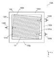
- FIG. 8 is a plan view schematically showing a polarizer unit 13A according to a modification.
- Spring-loaded screws 133A, 133B are provided on the wall 132d, and spring-loaded screws 133D are provided on the wall 132f.
- the spring-loaded screws 133A and 133B are movable with respect to the wall 132d, and the spring-loaded screw 133D is movable with respect to the wall 132f (see thick arrows in FIG. 8).
- the configuration of the spring-loaded screw 133D is the same as that of the spring-loaded screws 133A and 133B.
- the y-direction position of the spring-loaded screw 133D is adjusted, and then the y-direction positions of the spring-loaded screws 133A and 133B are respectively adjusted. Thereby, the polarizer 131 can be rotated to an arbitrary angle.
- a force in the ⁇ y direction is applied to the polarizer 131 by the coil spring 133c of the spring-loaded screws 133A and 133B. Accordingly, the side surface 131b is pressed against the wall 132f in a state where the polarizer 131 is rotated to an arbitrary angle.
- a force is applied to the side surface of the polarizer 131 using the spring-loaded screw 133 having the coil spring 133c.
- the elastic member that urges the force to the side surface of the polarizer 131 is It is not limited to this.
- a force is applied to the side surface of the polarizer using a leaf spring.
- the polarized light irradiation apparatus according to the second embodiment will be described below. Since the difference between the polarized light irradiation device 1 of the first embodiment and the polarized light irradiation device of the second embodiment is only the polarized light irradiation unit, only the polarized light irradiation unit will be described below. Further, the same parts as those of the first embodiment are denoted by the same reference numerals, and description thereof is omitted.
- FIG. 9 is a plan view showing an outline of the polarizer unit 13B in the polarized light irradiation unit 10A of the second embodiment.
- FIG. 10 is a cross-sectional view schematically showing the polarizer unit 13B.
- the polarized light irradiation unit 10 ⁇ / b> A mainly includes a light source 11, a specific wavelength transmission filter 12, a polarizer unit 13 ⁇ / b> B, and a base member 14.
- the polarizer unit 13 ⁇ / b> B mainly includes a polarizer 131, a holder 132, and a leaf spring 135.
- the plate spring 135 is formed by bending a metal plate material.
- the leaf spring 135 is provided on the wall 132d and contacts the side surface 131a of the polarizer 131.
- the leaf spring 135 biases the side surface 131b toward the wall 132f.
- the leaf spring 135 is formed by using a wide plate material so that the side 131a can be rotated without being rotated.
- the width of the leaf spring 135 is not limited to the case shown in FIG. Moreover, you may provide two leaf
- the polarizer 131 it is possible to prevent the polarizer 131 from rotating with respect to the holder 132 due to thermal expansion or contraction by pressing the polarizer 131 against the wall 132f.
- the polarizer 131 is positioned with respect to the holder 132 using the spring-loaded screw 133 having the coil spring 133c, but the holder 132 is not essential.
- the polarizer unit 13 that is, the holder 132 provided with the polarizer 131 is attached to the base member 14.
- the polarizer 131 may be directly provided on the base member 14 without using the holder 132.
- a polarizer is directly provided on the base member.
- the polarized light irradiation apparatus according to the third embodiment will be described. Since the difference between the polarized light irradiation device 1 of the first embodiment and the polarized light irradiation device of the third embodiment is only the polarized light irradiation unit, hereinafter the polarized light irradiation unit of the third embodiment. Only explained. Further, the same parts as those of the first embodiment are denoted by the same reference numerals, and description thereof is omitted.
- FIG. 11 is a perspective view illustrating an outline of a polarizer unit 13C in the polarized light irradiation unit 10B according to the third embodiment.
- the polarized light irradiation unit 10B mainly includes a light source 11, a specific wavelength transmission filter 12, and a polarizer unit 13C.
- the polarizer unit 13 ⁇ / b> C mainly includes a polarizer 131, a spring-loaded screw 133, and a base member 136.
- the base member 136 (corresponding to a holding member) is formed of a metal plate material. Walls 136a and 136b and a hole 136c are formed in the base member 136. The polarizer 131 is placed on the base member 136 so as to cover the hole 136c.
- the two spring-loaded screws 133 are provided on the wall 136b.
- a screw hole (not shown) is formed in the wall 136b, and the screw portion 133a is screwed into the screw hole, whereby the spring-loaded screw 133 is provided so as to be movable in the x direction.
- the spring-loaded screw 133 is in contact with the side surface 131d of the polarizer 131.
- the coil spring 133c of the spring-loaded screw 133 biases the side surface 131c opposite to the side surface 131d of the polarizer 131 toward the wall 136a via the ball 133b.
- the spring-loaded screw 133 presses the vicinity of both ends of the side surface 131d in order to prevent the polarizer 131 from rotating on the xy plane.
- the polarizer 131 can be prevented from rotating with respect to the base member 136 due to thermal expansion or contraction by pressing the polarizer 131 against the wall 136a.
- the polarizer 131 is rotated at an arbitrary angle by providing the wall 136a with a spring 133.
- the side surface 131c can be pressed against the wall 136a.
- the polarizer 131 can be biased to the wall 136a using a leaf spring.
- substantially is a concept that includes not only a case where they are exactly the same but also errors and deformations that do not lose the identity.
- the approximate center is not limited to the exact center.
- the “neighborhood” is a concept indicating that when it is in the vicinity of A, for example, it is near A and may or may not include A.
- Polarized light irradiation device 10 Polarized light irradiation unit 11: Light source 12: Specific wavelength transmission filters 13, 13A, 13B, 13C: Polarizer unit 20: Drive unit 21: Stage 22: Stage guide rail 30: Imaging unit 131: Polarization Child 131a, 131b, 131c, 131d: Side surface 132: Holder 132a: Hole 132b: Recess 132c: Bottom surface 132d, 132e, 132f, 132g: Wall 133, 133A, 133B, 133C, 133D: Spring-loaded screw 133a: Screw portion 133b: Ball 133c: coil springs 134, 135: leaf spring 136: base member 136a, 136b: wall 136c: hole
Landscapes
- Physics & Mathematics (AREA)
- Nonlinear Science (AREA)
- General Physics & Mathematics (AREA)
- Optics & Photonics (AREA)
- Spectroscopy & Molecular Physics (AREA)
- Mathematical Physics (AREA)
- Chemical & Material Sciences (AREA)
- Crystallography & Structural Chemistry (AREA)
- Polarising Elements (AREA)
- Liquid Crystal (AREA)
Abstract
熱膨張による不具合を防ぐことができる。 光源から出射された光を偏光する平面視略矩形形状の板状の偏光子の第1の側面に弾性部材が当接する。弾性部材は、偏光子の第1の側面と対向する側面を、保持部材の壁に向けて付勢する。
Description
本発明は、偏光光照射装置に関する。
特許文献1には、下フレームの上に複数のワイヤーグリッド偏光素子を並べ、その上から上フレームをかぶせることで、ワイヤーグリッド偏光素子を固定する偏光素子ユニットが開示されている。
光源から偏光素子ユニットに光が出射されると、熱により偏光素子ユニットの温度が上昇する。金属とガラスとは熱膨張係数が異なるため、金属で形成された偏光子支持部材やフレームと、ガラスで形成されたワイヤーグリッド偏光素子とでは、ある温度、例えば200度程度まで上昇したときの変形量が異なる。
特許文献1に記載の発明では、ワイヤーグリッド偏光素子がフレームに挟み込まれており、ワイヤーグリッド偏光素子とフレームとの間にすき間が無い。その結果、熱膨張による寸法変化がワイヤーグリッド偏光素子と偏光子支持部材とで異なることが原因で、ワイヤーグリッド偏光素子が割れる等の不具合が発生するおそれがある。
本発明はこのような事情に鑑みてなされたもので、熱膨張による不具合を防ぐことができる偏光光照射装置を提供することを目的とする。
上記課題を解決するために、本発明に係る偏光光照射装置は、例えば、光源と、前記光源から出射された光を偏光する平面視略矩形形状の板状の偏光子と、前記偏光子を保持する保持部材であって、前記偏光子の側面が当接する壁を有する保持部材と、前記保持部材に設けられ、前記偏光子の第1の側面に当接する弾性部材であって、前記偏光子の前記第1の側面と対向する側面を前記壁に向けて付勢する弾性部材と、を備えたことを特徴とする。
本発明に係る偏光光照射装置によれば、光源からの光を偏光する平面視略矩形形状の板状の偏光子の第1の側面に弾性部材が当接する。弾性部材は、偏光子の第1の側面と対向する側面を、保持部材の壁に向けて付勢する。これにより、偏光子を保持部材に取り付けつつ、熱膨張による不具合を防ぐことができる。ここで、熱膨張による不具合とは、偏光子の破損、変形、移動等である。
ここで、前記弾性部材は、前記偏光子の第1の側面に当接する第1の弾性部材と、前記偏光子の前記第1の側面に隣接する第2の側面に当接する第2の弾性部材と、を有し、前記壁は、直交する2つの壁である第1の壁と第2の壁とを有し、前記第1の弾性部材は、前記偏光子の前記第1の側面と対向する側面を、前記第1の壁に向けて付勢し、前記第2の弾性部材は、前記偏光子の前記第2の側面と対向する側面を、前記第2の側面に向けて付勢してもよい。これにより、偏光子の第1の側面と直交する平面上において、保持部材に対して偏光子を位置決めすることができる。
ここで、前記弾性部材は、前記偏光子に当接するボールと、前記ボールを前記偏光子に向けて付勢するばねと、前記ばねが内部に設けられたねじ部と、を有するばね付きねじであり、前記偏光子の厚さは、前記ねじ部の直径より厚くてもよい。これにより、ばね付きねじが偏光子の側面を確実に押圧することができる。
ここで、前記弾性部材は、2個のばねを有し、前記2個のばねは、前記第1の側面の両端近傍をそれぞれ押圧してもよい。これにより、偏光子の第1の側面と対向する側面を保持部材の壁に向けて付勢するときに、第1の側面と直交する平面上における偏光子の回転を防止することができる。
本発明によれば、熱膨張による不具合を防ぐことができる。
以下、本発明の実施形態を、図面を参照して詳細に説明する。
<第1の実施の形態>
図1は、第1の実施の形態に係る偏光光照射装置1の概略を示す正面図である。図2は、偏光光照射装置1の概略を示す側面図である。偏光光照射装置1は、例えば、光源からの光を偏光膜を通過させて偏光を得、この偏光をガラス基板等の被露光面に照射して、液晶パネル用の配向膜等を生成するものである。
<第1の実施の形態>
図1は、第1の実施の形態に係る偏光光照射装置1の概略を示す正面図である。図2は、偏光光照射装置1の概略を示す側面図である。偏光光照射装置1は、例えば、光源からの光を偏光膜を通過させて偏光を得、この偏光をガラス基板等の被露光面に照射して、液晶パネル用の配向膜等を生成するものである。
以下、被露光対象物Wの搬送方向をy方向とし、搬送方向に直交する方向をx方向とし、鉛直方向をz方向とする。
偏光光照射装置1は、主として、偏光照射部10と、駆動部20と、撮像部30と、を有する。
偏光照射部10は、被露光対象物Wに偏光を照射する。図2は、偏光照射部10の概略を示す平面図である。図3は、偏光照射部10の概略を示す側面図である。なお、図3の2点鎖線は、光が照射される範囲を示すものである。
偏光照射部10は、主として、光源11と、特定波長透過フィルター12と、偏光子ユニット13と、ベース部材14と、を有する。なお、図2では特定波長透過フィルター12の図示を省略している。
光源11は、棒状のランプであり、偏光していない光(例えば、紫外光)を出射する。光源は、長手方向がy方向に沿うように、かつx方向に複数並べて配置される。なお、光源11の形態はこれに限られず、例えばx方向に沿って長い1本のランプであっても良い。
特定波長透過フィルター12は、特定の波長範囲の光だけを透過し、他の波長の光をで吸収するようにつくられたフィルターである。特定波長透過フィルター12は、光源11の下側(-z側)に設けられる。
偏光子ユニット13は、特定波長透過フィルター12の下側(-z側)に設けられる。偏光子ユニット13は、例えば、光源11から出射された無偏光の光を偏光する偏光子を含む。偏光子ユニット13は、ベース部材14に設けられる。偏光子ユニット13については、後に詳述する。
特定波長透過フィルター12及び偏光子ユニット13は、光源11毎に1つずつ設けられる。なお、特定波長透過フィルター12及び偏光子ユニット13を、光源11毎に2つ設けてもよい。この場合には、特定波長透過フィルター12及び偏光子ユニット13を、y方向に並べて2つずつ設ければよい(図2の点線参照)。
図1の説明に戻る。駆動部20は、主として、ステージ21と、ステージガイドレール22と、を有する。
ステージ21は、図示しない駆動手段により、ステージガイドレール22に沿って移動可能に設けられる(図1の太矢印参照)。ステージ21の上面には、被露光対象物Wが載置される。
撮像部30は、ステージ21上に載置された被露光対象物Wのアライメントに使用するカメラである。
このように構成された偏光光照射装置1の作用について説明する。偏光光照射装置1は、被露光対象物Wを走査方向であるy方向に移動させながら、偏光照射部10から照射された光を被露光対象物Wの被露光面に照射して配向膜等を生成する。この偏光光照射装置1の作用は、すでに公知であるため、詳細な説明を省略する。なお、走査は、偏光照射部10を移動させてもよいし、被露光対象物W(ステージ21)を移動させてもよいし、それらの両方を相対的に移動させてもよい。
露光時には、光源11からの光が照射されるため、偏光子ユニット13の温度が上昇する。本発明は、偏光子ユニット13の温度が上昇することによる不具合を防止する点に特徴がある。以下、偏光子ユニット13について詳細に説明する。
図4は、偏光子ユニット13の概略を示す平面図である。図5は、偏光子ユニット13の概略を示す断面図である。偏光子ユニット13は、主として、偏光子131と、ホルダ132と、ばね付きねじ133(ばね付きねじ133は、ばね付きねじ133A、ばね付きねじ133B、ばね付きねじ133Cを含む)と、を有する。
偏光子131は、光源11からの光を偏光する光学素子であり、平面視が略矩形形状の板状の部材である。偏光子131は、例えば、ガラスにより形成された板材の表面に、金属製のワイヤーを一方向に周期的に並べることにより形成される。
偏光子131の厚さは、ばね付きねじ133のねじ部133a(後に詳述)の直径より厚い。例えば、偏光子131の厚さは3mm~7mm程度である。これにより、ばね付きねじ133が偏光子131の側面を確実に押圧することができる。
ホルダ132(保持部材に相当)は、金属により形成され、平面視が略中空矩形形状の板状の部材である。ホルダ132には、孔132aと、凹部132bと、が形成される。凹部132bの底面132cには、偏光子131が載置される。偏光子131で偏光された光は、孔132aを通って下方(-z方向)へ照射される。
ばね付きねじ133は、例えば、ねじ部133aと、偏光子131に当接するボール133bと、ボール133bを偏光子131に向けて付勢するコイルばね133c(弾性部材に相当)と、を有するボールプランジャーである。ボール133b及びコイルばね133cは、ねじ部133aの内部に設けられる。
2本のばね付きねじ133A、133Bは、壁132dに設けられる。壁132dにはねじ孔(図示せず)が形成され、このねじ孔にねじ部133aが螺合されることにより、ばね付きねじ133A、133Bが壁132dに設けられる。
また、1本のばね付きねじ133Cは、壁132eに設けられる。壁132eにはねじ孔(図示せず)が形成され、このねじ孔にねじ部133aが螺合されることにより、ばね付きねじ133Cが壁132eに設けられる。
ホルダ132に形成されたねじ孔にねじ部133aが螺合されるため、ばね付きねじ133は、ホルダ132の壁132d、132eの法線方向に移動可能である(図4、5の太矢印参照)。
ばね付きねじ133A、133Bは、偏光子131の側面131aに当接する。ばね付きねじ133A、133Bのコイルばね133cは、ボール133bを介して、偏光子131の側面131aと対向する側面131bを、壁132fに向けて付勢する(図4、5の矢印参照)。ばね付きねじ133A、133Bは、側面131bを壁132fに向けて付勢するときに偏光子131の回転を防止するため、側面131aの両端近傍をそれぞれ押圧する。なお、側面131aの両端近傍は、図4に示す位置に限られない。
ばね付きねじ133Cは、偏光子131の側面131aに隣接する側面131cに当接する。ばね付きねじ133Cのコイルばね133cは、ボール133bを介して偏光子131の側面131cと対向する側面131dを、壁132gに向けて付勢する(図4の矢印参照)。
このように、偏光子131には、コイルばね133cにより、側面131a、側面131cに、偏光子131の厚さ方向(z方向)と直交する方向(x方向又はy方向)の力が付勢される。これにより、偏光子131がホルダ132に設けられる。
壁132fと壁132gとは隣接し、壁132fはx方向と平行であり、壁132gはy方向と平行である。コイルばね133cにより、偏光子131が壁132f、132gに押圧されることで、xy平面と平行な平面上において、ホルダ132に対して偏光子131が位置決めされる。
本実施の形態によれば、偏光子131をホルダ132の壁132f、132gに押圧することで、偏光子131をホルダ132に設けつつ、熱膨張による不具合を防ぐことができる。
従来のように偏光子131をホルダ132に接着する場合には、熱膨張による寸法変化が偏光子131とホルダ132とで異なることが原因で、偏光子131が割れてしまうおそれがある。それに対し、本実施の形態では、弾性部材を用いて偏光子131をホルダ132に設けるため、偏光子131が割れてしまうことを防止することができる。
また、例えば、図6に示すように、板ばね134を用いて偏光子131を底面132cに付勢する(-z方向に押圧する)ことで偏光子131をホルダ132に設ける偏光子ユニット130も考えられる。この場合には、偏光子131が割れてしまうおそれは小さい。ただし、偏光子131を凹部132b内に設けるためには、偏光子131が熱膨張することを見込んで、凹部132bの大きさを偏光子131の大きさより大きくする必要がある。そのため、熱膨張と収縮を繰り返すと、図7に示すように、偏光子131が凹部132b内で回転してしまうおそれがある。
それに対し、本実施の形態では、偏光子131の板厚が厚いため、コイルばね133cにより、z方向と直交するx方向又はy方向の力を偏光子131に直接付勢することができる。したがって、xy平面と平行な平面上において、ホルダ132に対して偏光子131を位置決めすることで、熱膨張による寸法変化が偏光子131とホルダ132とで異なる場合でも、偏光子131がホルダ132内で回転(移動を含む。以下同じ)してしまうことを防止できる。
なお、本実施の形態では、偏光子131の厚さは、ばね付きねじ133のねじ部133aの直径より厚いが、偏光子131の厚さはこれに限られない。例えば、偏光子131の厚さは、ばね付きねじ133のボール133bが当接可能、かつコイルばね133cが力を付勢可能な厚さであればよい。
また、本実施の形態では、側面131bを壁132fに押圧し、側面131dを壁132gに押圧することで偏光子131の回転を防止したが、偏光子131の回転を防止するためには、少なくとも側面131bを壁132fに押圧すればよい。
また、偏光子131を任意の角度に回転させた状態で、側面131bを壁132fに押圧することもできる。図8は、変形例にかかる偏光子ユニット13Aの概略を示す平面図である。
ばね付きねじ133A、133Bが壁132dに設けられ、ばね付きねじ133Dが壁132fに設けられる。ばね付きねじ133A、133Bは、壁132dに対して移動可能であり、ばね付きねじ133Dは、壁132fに対して移動可能である(図8の太矢印参照)。ばね付きねじ133Dの構成は、ばね付きねじ133A、133Bと同様である。
まず、ばね付きねじ133Dのy方向の位置を調整し、次に、ばね付きねじ133A、133Bのy方向の位置をそれぞれ調整する。これにより、偏光子131を任意の角度に回転させることができる。
ばね付きねじ133A、133Bのコイルばね133cにより、偏光子131には-y方向の力が付勢される。これにより、偏光子131を任意の角度に回転させた状態で、側面131bが壁132fに押圧される。
<第2の実施の形態>
本発明の第1の実施の形態は、コイルばね133cを有するばね付きねじ133を用いて偏光子131の側面に力を付勢したが、偏光子131の側面に力を付勢する弾性部材はこれに限られない。
本発明の第1の実施の形態は、コイルばね133cを有するばね付きねじ133を用いて偏光子131の側面に力を付勢したが、偏光子131の側面に力を付勢する弾性部材はこれに限られない。
第2の実施の形態は、板ばねを用いて偏光子の側面に力を付勢する形態である。以下、第2の実施の形態の偏光光照射装置について説明する。第1の実施の形態の偏光光照射装置1と、第2の実施の形態の偏光光照射装置との差異は、偏光照射部のみであるため、以下偏光照射部についてのみ説明する。また、第1の実施の形態と同一の部分については、同一の符号を付し、説明を省略する。
図9は、第2の実施の形態の偏光照射部10Aにおける偏光子ユニット13Bの概略を示す平面図である。図10は、偏光子ユニット13Bの概略を示す断面図である。
偏光照射部10Aは、主として、光源11と、特定波長透過フィルター12と、偏光子ユニット13Bと、ベース部材14と、を有する。また、偏光子ユニット13Bは、主として、偏光子131と、ホルダ132と、板ばね135と、を有する。
板ばね135は、金属製の板材を折り曲げて形成される。板ばね135は、壁132dに設けられ、偏光子131の側面131aに当接する。板ばね135は、側面131bを壁132fに向けて付勢する。板ばね135は、側面131aを回転させず、均等に力を付勢できるように、幅広の板材を用いて形成される。
なお、板ばね135の幅は図9に示す場合に限られない。また、側面131aの両端近傍をそれぞれ押圧する2つの板ばねを設けてもよい。また、偏光子131の板厚は、板ばね135が当接可能な厚さであればよい。
本実施の形態によれば、偏光子131を壁132fに押圧することで、熱膨張や収縮により、偏光子131がホルダ132に対して回転することを防止することができる。
<第3の実施の形態>
本発明の第1の実施の形態は、コイルばね133cを有するばね付きねじ133を用いて偏光子131をホルダ132に対して位置決めしたが、ホルダ132は必須ではない。例えば、図2の点線で示すように、偏光子ユニット13を1つの光源11に対して2つ設ける場合には、偏光子ユニット13、すなわち偏光子131が設けられたホルダ132を、ベース部材14上にy方向に並べて2つ設けるが、ホルダ132を用いず、ベース部材14に偏光子131を直接設けてもよい。
本発明の第1の実施の形態は、コイルばね133cを有するばね付きねじ133を用いて偏光子131をホルダ132に対して位置決めしたが、ホルダ132は必須ではない。例えば、図2の点線で示すように、偏光子ユニット13を1つの光源11に対して2つ設ける場合には、偏光子ユニット13、すなわち偏光子131が設けられたホルダ132を、ベース部材14上にy方向に並べて2つ設けるが、ホルダ132を用いず、ベース部材14に偏光子131を直接設けてもよい。
第3の実施の形態は、ベース部材に偏光子を直接設ける形態である。以下、第3の実施の形態の偏光光照射装置について説明する。第1の実施の形態の偏光光照射装置1と、第3の実施の形態の偏光光照射装置との差異は、偏光照射部のみであるため、以下第3の実施の形態の偏光照射部についてのみ説明する。また、第1の実施の形態と同一の部分については、同一の符号を付し、説明を省略する。
図11は、第3の実施の形態の偏光照射部10Bにおける偏光子ユニット13Cの概略を示す斜視図である。
偏光照射部10Bは、主として、光源11と、特定波長透過フィルター12と、偏光子ユニット13Cと、を有する。また、偏光子ユニット13Cは、主として、偏光子131と、ばね付きねじ133と、ベース部材136と、を有する。
ベース部材136(保持部材に相当)は、金属の板材で形成される。ベース部材136には、壁136a、136bと、孔136cと、が形成される。ベース部材136には、孔136cを覆うように、偏光子131が載置される。
2本のばね付きねじ133は、壁136bに設けられる。壁136bにはねじ孔(図示せず)が形成され、このねじ孔にねじ部133aが螺合されることにより、ばね付きねじ133が、x方向に移動可能に設けられる。
ばね付きねじ133は、偏光子131の側面131dに当接する。ばね付きねじ133のコイルばね133cは、ボール133bを介して、偏光子131の側面131dと対向する側面131cを、壁136aに向けて付勢する。ばね付きねじ133は、xy平面上における偏光子131の回転を防止するため、側面131dの両端近傍をそれぞれ押圧する。
本実施の形態によれば、偏光子131を壁136aに押圧することで、熱膨張や収縮により、偏光子131がベース部材136に対して回転することを防止することができる。
なお、第3の実施の形態についても、第1の実施の形態の変形例と同様に、壁136aにもばね付きねじ133を設けることで、偏光子131を任意の角度に回転させた状態で、側面131cを壁136aに押圧することもできる。また、第3の実施の形態についても、第2の実施の形態と同様に、板ばねを用いて偏光子131を壁136aに付勢することもできる。
以上、この発明の実施形態を、図面を参照して詳述してきたが、具体的な構成はこの実施形態に限られるものではなく、この発明の要旨を逸脱しない範囲の設計変更等も含まれる。
また、本発明において、「略」とは、厳密に同一である場合のみでなく、同一性を失わない程度の誤差や変形を含む概念である。例えば、略中央とは、厳密に中央の場合には限られない。また、例えば、単に平行、直交等と表現する場合において、厳密に平行、直交等の場合のみでなく、略平行、略直交等の場合を含むものとする。また、本発明において「近傍」とは、例えばAの近傍であるときに、Aの近くであって、Aを含んでもいても含んでいなくてもよいことを示す概念である。
1 :偏光光照射装置
10 :偏光照射部
11 :光源
12 :特定波長透過フィルター
13、13A、13B、13C:偏光子ユニット
20 :駆動部
21 :ステージ
22 :ステージガイドレール
30 :撮像部
131 :偏光子
131a、131b、131c、131d:側面
132 :ホルダ
132a :孔
132b :凹部
132c :底面
132d、132e、132f、132g:壁
133、133A、133B、133C、133D:ばね付きねじ
133a :ねじ部
133b :ボール
133c :コイルばね
134、135:板ばね
136 :ベース部材
136a、136b:壁
136c :孔
10 :偏光照射部
11 :光源
12 :特定波長透過フィルター
13、13A、13B、13C:偏光子ユニット
20 :駆動部
21 :ステージ
22 :ステージガイドレール
30 :撮像部
131 :偏光子
131a、131b、131c、131d:側面
132 :ホルダ
132a :孔
132b :凹部
132c :底面
132d、132e、132f、132g:壁
133、133A、133B、133C、133D:ばね付きねじ
133a :ねじ部
133b :ボール
133c :コイルばね
134、135:板ばね
136 :ベース部材
136a、136b:壁
136c :孔
Claims (4)
- 光源と、
前記光源から出射された光を偏光する平面視略矩形形状の板状の偏光子と、
前記偏光子を保持する保持部材であって、前記偏光子の側面が当接する壁を有する保持部材と、
前記保持部材に設けられ、前記偏光子の第1の側面に当接する弾性部材であって、前記偏光子の前記第1の側面と対向する側面を前記壁に向けて付勢する弾性部材と、
を備えたことを特徴とする偏光光照射装置。 - 前記弾性部材は、前記偏光子の第1の側面に当接する第1の弾性部材と、前記偏光子の前記第1の側面に隣接する第2の側面に当接する第2の弾性部材と、を有し、
前記壁は、直交する2つの壁である第1の壁と第2の壁とを有し、
前記第1の弾性部材は、前記偏光子の前記第1の側面と対向する側面を、前記第1の壁に向けて付勢し、
前記第2の弾性部材は、前記偏光子の前記第2の側面と対向する側面を、前記第2の側面に向けて付勢する
ことを特徴とする請求項1に記載の偏光光照射装置。 - 前記弾性部材は、前記偏光子に当接するボールと、前記ボールを前記偏光子に向けて付勢するばねと、前記ばねが内部に設けられたねじ部と、を有するばね付きねじであり、
前記偏光子の厚さは、前記ねじ部の直径より厚い
ことを特徴とする請求項1又は2に記載の偏光光照射装置。 - 前記弾性部材は、2個のばねを有し、
前記2個のばねは、前記第1の側面の両端近傍をそれぞれ押圧する
ことを特徴とする請求項1から3のいずれか1項に記載の偏光光照射装置。
Priority Applications (2)
| Application Number | Priority Date | Filing Date | Title |
|---|---|---|---|
| KR1020177027259A KR20170136518A (ko) | 2015-04-14 | 2016-04-12 | 편광 광조사 장치 |
| CN201680020866.6A CN107430305A (zh) | 2015-04-14 | 2016-04-12 | 偏振光照射装置 |
Applications Claiming Priority (2)
| Application Number | Priority Date | Filing Date | Title |
|---|---|---|---|
| JP2015082804A JP6500204B2 (ja) | 2015-04-14 | 2015-04-14 | 偏光光照射装置 |
| JP2015-082804 | 2015-04-14 |
Publications (1)
| Publication Number | Publication Date |
|---|---|
| WO2016167244A1 true WO2016167244A1 (ja) | 2016-10-20 |
Family
ID=57126790
Family Applications (1)
| Application Number | Title | Priority Date | Filing Date |
|---|---|---|---|
| PCT/JP2016/061791 Ceased WO2016167244A1 (ja) | 2015-04-14 | 2016-04-12 | 偏光光照射装置 |
Country Status (5)
| Country | Link |
|---|---|
| JP (1) | JP6500204B2 (ja) |
| KR (1) | KR20170136518A (ja) |
| CN (1) | CN107430305A (ja) |
| TW (1) | TWI728970B (ja) |
| WO (1) | WO2016167244A1 (ja) |
Cited By (1)
| Publication number | Priority date | Publication date | Assignee | Title |
|---|---|---|---|---|
| KR20180061047A (ko) * | 2016-11-29 | 2018-06-07 | 상하이 마이크로 일렉트로닉스 이큅먼트(그룹) 컴퍼니 리미티드 | 와이어 그리드 유닛 및 와이어 그리드 결합 보호 장치 |
Citations (3)
| Publication number | Priority date | Publication date | Assignee | Title |
|---|---|---|---|---|
| JP2012093692A (ja) * | 2010-09-28 | 2012-05-17 | Ushio Inc | 光照射装置および光照射方法 |
| JP2014010388A (ja) * | 2012-07-02 | 2014-01-20 | Harison Toshiba Lighting Corp | 偏光光照射装置 |
| WO2014062800A1 (en) * | 2012-10-18 | 2014-04-24 | Polarization Solutions, Llc | Apparatus and method for mosaic gratings-based polarizer |
Family Cites Families (13)
| Publication number | Priority date | Publication date | Assignee | Title |
|---|---|---|---|---|
| CN2496686Y (zh) * | 2001-09-20 | 2002-06-26 | 宝安区公明镇东坑海王星运动用品厂 | 可伸缩万向脚轮 |
| CN2803895Y (zh) * | 2004-11-29 | 2006-08-09 | 萧博文 | 一种自行车转轴定位装置 |
| US20070127144A1 (en) * | 2005-12-06 | 2007-06-07 | Eastman Kodak Company | Optical film and frame with high resistance to thermal distortion |
| CN101363170B (zh) * | 2008-09-12 | 2012-05-02 | 浙江宝石机电股份有限公司 | 缝纫机滚轮调节装置 |
| CN201359237Y (zh) * | 2009-03-06 | 2009-12-09 | 北京京东方光电科技有限公司 | 背光模组 |
| JP5200271B1 (ja) * | 2012-01-25 | 2013-06-05 | ウシオ電機株式会社 | 偏光光照射装置 |
| JP2013160863A (ja) * | 2012-02-02 | 2013-08-19 | Jiroo Corporate Plan:Kk | 偏光子保護フィルム、偏光板及び液晶表示素子 |
| CN102635816B (zh) * | 2012-03-29 | 2015-09-09 | 深圳市华星光电技术有限公司 | 背光模块及液晶显示装置 |
| JP5652424B2 (ja) * | 2012-04-03 | 2015-01-14 | ウシオ電機株式会社 | 偏光素子ユニット及び偏光光照射装置 |
| CN102798049A (zh) * | 2012-08-15 | 2012-11-28 | 友达光电(苏州)有限公司 | 一种背光模组 |
| CN103341809B (zh) * | 2013-06-19 | 2015-06-17 | 山东英才学院 | 一种平行分度凸轮精加工装置及方法 |
| KR101622005B1 (ko) * | 2013-08-22 | 2016-05-17 | 제일모직주식회사 | 편광판용 점착 필름, 이를 포함하는 편광판 및 이를 포함하는 광학표시장치 |
| CN203525929U (zh) * | 2013-11-05 | 2014-04-09 | 苏州翔之盛真空科技有限公司 | 可自动调位的固定治具 |
-
2015
- 2015-04-14 JP JP2015082804A patent/JP6500204B2/ja not_active Expired - Fee Related
-
2016
- 2016-04-08 TW TW105111041A patent/TWI728970B/zh not_active IP Right Cessation
- 2016-04-12 CN CN201680020866.6A patent/CN107430305A/zh active Pending
- 2016-04-12 WO PCT/JP2016/061791 patent/WO2016167244A1/ja not_active Ceased
- 2016-04-12 KR KR1020177027259A patent/KR20170136518A/ko not_active Ceased
Patent Citations (3)
| Publication number | Priority date | Publication date | Assignee | Title |
|---|---|---|---|---|
| JP2012093692A (ja) * | 2010-09-28 | 2012-05-17 | Ushio Inc | 光照射装置および光照射方法 |
| JP2014010388A (ja) * | 2012-07-02 | 2014-01-20 | Harison Toshiba Lighting Corp | 偏光光照射装置 |
| WO2014062800A1 (en) * | 2012-10-18 | 2014-04-24 | Polarization Solutions, Llc | Apparatus and method for mosaic gratings-based polarizer |
Cited By (3)
| Publication number | Priority date | Publication date | Assignee | Title |
|---|---|---|---|---|
| KR20180061047A (ko) * | 2016-11-29 | 2018-06-07 | 상하이 마이크로 일렉트로닉스 이큅먼트(그룹) 컴퍼니 리미티드 | 와이어 그리드 유닛 및 와이어 그리드 결합 보호 장치 |
| TWI658255B (zh) * | 2016-11-29 | 2019-05-01 | 大陸商上海微電子裝備(集團)股份有限公司 | Wire grid unit and wire grid splicing protection device |
| KR101985346B1 (ko) * | 2016-11-29 | 2019-06-03 | 상하이 마이크로 일렉트로닉스 이큅먼트(그룹) 컴퍼니 리미티드 | 와이어 그리드 유닛 및 와이어 그리드 결합 보호 장치 |
Also Published As
| Publication number | Publication date |
|---|---|
| JP2016200780A (ja) | 2016-12-01 |
| TWI728970B (zh) | 2021-06-01 |
| TW201640185A (zh) | 2016-11-16 |
| CN107430305A (zh) | 2017-12-01 |
| JP6500204B2 (ja) | 2019-04-17 |
| KR20170136518A (ko) | 2017-12-11 |
Similar Documents
| Publication | Publication Date | Title |
|---|---|---|
| JP4260219B2 (ja) | 表示パネルの製造方法、表示パネルの製造装置、及び表示パネル | |
| JP5200271B1 (ja) | 偏光光照射装置 | |
| CN103765303A (zh) | 光定向照射装置 | |
| KR102033697B1 (ko) | 광학 필름 마킹 시스템 및 광학 필름 마킹 방법 | |
| CN203241563U (zh) | 偏振元件单元以及偏振光照射装置 | |
| JP6578075B2 (ja) | 偏光光照射装置 | |
| JP6500204B2 (ja) | 偏光光照射装置 | |
| JP6500543B2 (ja) | 偏光子、光配向装置、および光配向方法 | |
| KR102387205B1 (ko) | 광배향 장치 및 이를 이용한 광배향 방법 | |
| US9310550B2 (en) | Positioning device for light guide plate and backlight module | |
| JP6887360B2 (ja) | 偏光装置、及び光配向膜の製造方法 | |
| TWI611223B (zh) | 偏光板之製造方法及液晶面板之製造方法 | |
| CN107085273A (zh) | 偏振元件单元以及偏振光照射装置 | |
| JP6149214B2 (ja) | 露光装置、露光方法 | |
| JP2010002571A (ja) | 基板露光装置 | |
| JPH11274276A (ja) | 基板保持装置 | |
| CN107085272B (zh) | 偏振元件单元、偏振光照射装置及偏振光照射方法 | |
| JP5825392B2 (ja) | 偏光光照射装置 | |
| JP2013152433A (ja) | 偏光光照射装置 | |
| KR102337780B1 (ko) | 편광판 및 그 제조방법, 및 이를 구비한 액정표시장치 | |
| KR20100105463A (ko) | 광학 장치 | |
| CN110007500B (zh) | 显示装置 | |
| JP2017032869A (ja) | 光学ユニット及び光照射装置 | |
| CN115586673A (zh) | 偏振光照射装置、具备其的曝光装置以及偏振光照射方法 | |
| JP2019053200A (ja) | 光照射装置 |
Legal Events
| Date | Code | Title | Description |
|---|---|---|---|
| 121 | Ep: the epo has been informed by wipo that ep was designated in this application |
Ref document number: 16780035 Country of ref document: EP Kind code of ref document: A1 |
|
| ENP | Entry into the national phase |
Ref document number: 20177027259 Country of ref document: KR Kind code of ref document: A |
|
| NENP | Non-entry into the national phase |
Ref country code: DE |
|
| 122 | Ep: pct application non-entry in european phase |
Ref document number: 16780035 Country of ref document: EP Kind code of ref document: A1 |