WO2016167124A1 - Borne, câblage équipé de borne et procédé de fabrication de câblage équipé de borne - Google Patents
Borne, câblage équipé de borne et procédé de fabrication de câblage équipé de borne Download PDFInfo
- Publication number
- WO2016167124A1 WO2016167124A1 PCT/JP2016/060335 JP2016060335W WO2016167124A1 WO 2016167124 A1 WO2016167124 A1 WO 2016167124A1 JP 2016060335 W JP2016060335 W JP 2016060335W WO 2016167124 A1 WO2016167124 A1 WO 2016167124A1
- Authority
- WO
- WIPO (PCT)
- Prior art keywords
- terminal
- electric wires
- electric wire
- holding
- conductor
- Prior art date
Links
Images


Classifications
-
- H—ELECTRICITY
- H01—ELECTRIC ELEMENTS
- H01R—ELECTRICALLY-CONDUCTIVE CONNECTIONS; STRUCTURAL ASSOCIATIONS OF A PLURALITY OF MUTUALLY-INSULATED ELECTRICAL CONNECTING ELEMENTS; COUPLING DEVICES; CURRENT COLLECTORS
- H01R4/00—Electrically-conductive connections between two or more conductive members in direct contact, i.e. touching one another; Means for effecting or maintaining such contact; Electrically-conductive connections having two or more spaced connecting locations for conductors and using contact members penetrating insulation
- H01R4/10—Electrically-conductive connections between two or more conductive members in direct contact, i.e. touching one another; Means for effecting or maintaining such contact; Electrically-conductive connections having two or more spaced connecting locations for conductors and using contact members penetrating insulation effected solely by twisting, wrapping, bending, crimping, or other permanent deformation
- H01R4/18—Electrically-conductive connections between two or more conductive members in direct contact, i.e. touching one another; Means for effecting or maintaining such contact; Electrically-conductive connections having two or more spaced connecting locations for conductors and using contact members penetrating insulation effected solely by twisting, wrapping, bending, crimping, or other permanent deformation by crimping
-
- H—ELECTRICITY
- H01—ELECTRIC ELEMENTS
- H01R—ELECTRICALLY-CONDUCTIVE CONNECTIONS; STRUCTURAL ASSOCIATIONS OF A PLURALITY OF MUTUALLY-INSULATED ELECTRICAL CONNECTING ELEMENTS; COUPLING DEVICES; CURRENT COLLECTORS
- H01R43/00—Apparatus or processes specially adapted for manufacturing, assembling, maintaining, or repairing of line connectors or current collectors or for joining electric conductors
-
- H—ELECTRICITY
- H01—ELECTRIC ELEMENTS
- H01R—ELECTRICALLY-CONDUCTIVE CONNECTIONS; STRUCTURAL ASSOCIATIONS OF A PLURALITY OF MUTUALLY-INSULATED ELECTRICAL CONNECTING ELEMENTS; COUPLING DEVICES; CURRENT COLLECTORS
- H01R9/00—Structural associations of a plurality of mutually-insulated electrical connecting elements, e.g. terminal strips or terminal blocks; Terminals or binding posts mounted upon a base or in a case; Bases therefor
- H01R9/03—Connectors arranged to contact a plurality of the conductors of a multiconductor cable, e.g. tapping connections
Definitions
- the technique disclosed by this specification is related with the manufacturing method of a terminal, an electric wire with a terminal, and an electric wire with a terminal.
- an electric wire with a terminal formed by connecting a plurality of electric wires to one terminal is used.
- an electric wire with a terminal the thing of patent document 1, etc. are known, for example.
- the electric wire with a terminal described in Patent Document 1 is a wire in which a plurality of electric wires are arranged side by side on a connection portion and connected, and the thickness of the conductor is different by forming the connection portion in a stepped shape. Can be connected evenly.
- the electric wire with a terminal is used in various environments. Depending on various conditions such as restrictions on installation space and wiring direction, it may be desirable to use a terminal in which a plurality of electric wires are arranged in a vertical and vertical arrangement, and such electric wires with terminals are desired.
- a terminal in which a plurality of electric wires are arranged in a vertical and vertical arrangement, and such electric wires with terminals are desired.
- various forces act on the electric wire connected to the terminal. For this reason, it is desirable to secure the connection reliability of the electric wire by connecting the electric wire and the terminal under stable conditions and connecting the electric wire and the terminal evenly.
- it has sufficient resistance (stripping strength) against the force that urges the plurality of wires connected to the terminal upward to the connecting portion, that is, the force that tries to peel off the connecting portion.
- it is.
- connection means that the connection is performed so that no distinctly different part is formed in the conductor in the connection part.
- the reason for the formation of the above heterogeneous parts is that the pressure applied in the connection process is not evenly transmitted to the entire conductor, and the part that receives too little or too much pressure is locally generated. In other words, it may not melt well or deteriorate.
- this specification discloses a technique for providing a terminal-attached electric wire that is a terminal-attached electric wire in which a plurality of electric wires are arranged in a vertical and vertical manner and connected, and has excellent connection reliability.
- the terminal disclosed in the present specification is a terminal for connecting and holding a plurality of electric wires including an exposed conductor in which the conductor is exposed from an end portion of an insulating coating that covers the periphery of the conductor, and the plurality of electric wires are connected to each other.
- a base part that is placed and connected to the exposed conductor; and a holding part that holds the plurality of electric wires placed on the base part side by side.
- the holding portion includes a left holding piece and a right holding piece that extend upward from the left and right sides of the base, respectively, and holds the plurality of electric wires from the left and right sides with the left holding piece and the right holding piece.
- a terminal that can connect and connect a plurality of electric wires in the vertical and vertical directions and that can provide an electric wire with a terminal that has excellent connection reliability. That is, by appropriately adjusting the width between the left holding piece and the right holding piece that supports the plurality of electric wires placed on the pedestal from both the left and right sides according to the thickness dimension of the electric wire to be connected and held, A plurality of electric wires can be supported on the pedestal so as not to be shifted from side to side. Therefore, if the connection between the electric wire and the terminal is performed in this state, the connection between the electric wire and the terminal can be executed under a stable condition, so that an electric wire with a terminal having high connection reliability can be obtained. Moreover, since the terminal has a structure for supporting a plurality of electric wires placed on the base, it is not necessary to separately provide a jig for supporting the electric wires during welding.
- the present specification includes a terminal having a plurality of electric wires including an exposed conductor in which the conductor is exposed from an end portion of an insulating coating that covers the periphery of the conductor, and a terminal that connects and holds the plurality of electric wires vertically.
- the terminal includes a base portion on which the plurality of electric wires are placed and connected to the exposed conductor, and a holding portion that holds the plurality of electric wires placed on the base portion side by side vertically. And the holding portion holds the plurality of electric wires from both the left and right sides so that the electric wire arranged at a high position has a thickness dimension larger than that of the electric wires arranged at a low position.
- the present specification includes a plurality of electric wires including an exposed conductor in which the conductor is exposed from an end portion of an insulating coating that covers the periphery of the conductor, and a terminal that includes a base portion and a holding portion to connect and hold the plurality of electric wires.
- the plurality of electric wires are placed on the base so that the electric wires arranged at a high position have a thickness dimension larger than that of the electric wires arranged at a low position.
- a method of manufacturing a terminal-attached electric wire that executes a connecting step of connecting the exposed conductor and the base from above and below while pressing after placing the supporting step supported by the holding portion from both left and right sides is disclosed. To do.
- a terminal-attached electric wire that is a terminal-attached electric wire in which a plurality of electric wires are arranged in the vertical and vertical directions and has excellent connection reliability. That is, according to the said structure, a some electric wire is supported from the right-and-left both sides by the holding
- the above configuration it is possible to obtain a terminal-attached electric wire with particularly improved electric wire peeling strength as compared with the conventional one. That is, in the electric wire with a terminal according to the above configuration, since the plurality of electric wires are connected to the base of the terminal in a vertically and vertically arranged manner, the electric wires arranged below among the plurality of electric wires are arranged upward. In addition to being pressed down by the electric wire, the upper electric wire is also connected with the lower electric wire and the conductor integrated, and the peel strength compared to the case where it is connected to the stand alone Will improve.
- a conductor of a thin electric wire having a small conductor thickness and inferior peeling strength is disposed at a lower position, and the thick electric wire disposed above is arranged. While being integrated so as to be wrapped with a conductor having a large thickness, it is connected to the base. Therefore, it is possible to improve the peeling strength of particularly thin electric wires, and to secure high connection reliability as a whole.
- the holding portion extends upward from the left and right sides of the base portion, and A right holding piece is provided, and a width between the left holding piece and the right holding piece is wider on the upper side than the lower side, and a plurality of electric wires having different thickness dimensions are connected and held. Also good.
- a plurality of electric wires having different thickness dimensions can be evenly connected to the terminals. That is, in the terminal having the above configuration, even when the thickness dimensions of the respective electric wires constituting the plurality of electric wires are different by appropriately setting the width between the left holding piece and the right holding piece at each height, Can be supported while restricting the movement of the electric wire in the left-right direction. Therefore, a plurality of electric wires having different thickness dimensions can be evenly connected to the terminals under stable conditions.
- the width between the left holding piece and the right holding piece is wider on the upper side than the lower side, the electric wire having a large thickness among the electric wires is arranged above, and the above-mentioned As described above, the peeling strength of particularly thin electric wires is improved, and high connection reliability can be ensured as a whole.
- the holding portion may be configured to be crimped to the insulating coating of the plurality of electric wires.
- the holding portion since the holding portion is pressure-bonded to the insulating coating, the plurality of electric wires are held on the terminal so that the outer periphery is held. Therefore, the connection reliability with respect to peeling can be further improved.
- the holding portion since the holding portion has a function of holding the electric wire and a function of caulking the electric wire, the connection is strong with a simple structure without separately providing a member for caulking the electric wire. Can be.
- the holding part since the holding part is crimped to the insulation coating rather than the exposed conductor, the holding part becomes an obstacle when performing the connection process, or the crimped holding part damages the conductor and reduces connection reliability. There is no fear of it.
- a terminal-attached electric wire that is a terminal-attached electric wire in which a plurality of electric wires are arranged vertically and connected, and has excellent connection reliability.
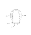
- the perspective view of the electric wire with a terminal concerning one embodiment Front view of electric wire with terminal Terminal perspective view Rear view of terminals Terminal side view
- FIGS. 1 and 2 are a perspective view and a front view of a terminal-attached electric wire 1 according to the present embodiment.
- the terminal-attached electric wire 1 includes a plurality (two in the present embodiment) of electric wires 3A and 3B and a terminal 2 that holds the plurality of electric wires 3A and 3B side by side.
- the upper side in FIG. 1 is the upper side (the lower side is the lower side)
- the left front side is the front or front
- the rear right side is the rear or the rear
- the left rear side is the left (the right front side is the right).
- the electric wires 3A and 3B connected to the terminal 2 are obtained by covering the conductors 31A and 31B with insulating coatings 32A and 32B made of synthetic resin. At the ends of the electric wires 3A and 3B, the insulation coatings 32A and 32B are stripped off, and the conductors 31A and 31B are exposed to form exposed conductors.
- the conductors 31A and 31B are made of a metal material such as aluminum, aluminum alloy, copper, or copper alloy.
- a stranded wire in which a plurality of metal strands are twisted is used, but it may be a single wire.
- the cross-sectional shapes of the electric wires 3A and 3B and the conductors 31A and 31B are substantially circular.
- the electric wires 3A and 3B are different from each other in thickness, and an electric wire having a large thickness is referred to as a first electric wire 3A, and an electric wire having a thickness smaller than that of the first electric wire 3A is referred to as a second electric wire 3B.
- each electric wire 3A, 3B is provided with the conductor from which a thickness dimension mutually differs
- the 1st electric wire 3A is the 1st conductor 31A with a large thickness dimension
- the 2nd electric wire 3B is the 2nd conductor with a small thickness dimension. 31B is provided.
- the radii of the electric wires 3A and 3B are R A and R B
- the radii of the conductors 31A and 31B are R a and R b (FIG. 7). That is, R A > R a and R B > R b , and R A ⁇ R B and R a ⁇ R b .
- Each conductor 31A but it is not limited thickness of 31B, for example, R a and about 4.0 mm ⁇ 6.0 mm, a R b may be about 1.5 mm ⁇ 3.5 mm.
- the first electric wire 3A is connected and held on the terminal 2 so that the first electric wire 3A is arranged at a higher position than the second electric wire.
- the terminal 2 includes a base portion 21 and a holding portion 22, and is formed of a metal material such as copper, copper alloy, aluminum, or aluminum alloy.
- a metal material such as copper, copper alloy, aluminum, or aluminum alloy.
- the surface of the metal material which comprises the terminal 2 may be plated as needed.
- the base portion 21 of the present embodiment includes a flat plate-like connecting portion 211, an inclined portion 212 connected to the rear of the connecting portion 211, and an electric wire receiving portion 213 connected to the rear of the inclined portion 212.
- the upper surface (mounting surface) of the connection portion 211 having a substantially square shape when viewed from above is formed in a flat horizontal plane.
- the second conductor 31B is mounted on the connection portion 211, and this The first conductor 31A is placed on and connected to the two conductors 31B.
- the upper surface of the electric wire receiving portion 213 is formed in a curved shape along the outer periphery of the second electric wire 3B, and is supported in a state where the second electric wire 3B is fitted to this curved surface (FIG.
- the upper surface of the inclined portion 212 is formed in such a shape that both surfaces are smoothly continuous while being inclined downward from the upper surface of the connecting portion 211 toward the upper surface of the wire receiving portion 213. For this reason, stress concentration in the exposed conductor portion can be avoided during manufacture and use of the electric wire 1 with a terminal.
- the holding part 22 has a left holding piece 221A that extends upward from the left side of the wire receiving part 213 and a right holding piece 221B that also extends from the right side.
- the holding pieces 221A and 221B are formed substantially symmetrically with respect to the vertical plane ⁇ that passes through the left and right centers of the rear end of the connecting portion 211 and is parallel to the direction in which the electric wires 3A and 3B are led out.
- Step portions 222A and 222B are provided.
- the step portion 222A, 222B, the height of the center upper surface of the wire receiving portion 213 at a position lower than the higher (2R B + R A) than R B, are provided ( Figure 4).
- proximal end 223A is assumed substantially equal to the radius R B of the second wire 3B, the step portion upward In the separation portions 224A and 224B that are separated from each other via 222A and 222B, they are substantially equal to the radius RA of the first electric wire 3A (FIG. 4).
- the extending ends of the holding pieces 221A and 221B are referred to as tip portions 225A and 225B.
- extension length of the left holding piece 221A and the right holding piece 221B is a length that substantially goes around the outer circumference of the two electric wires 3A and 3B held between them together with the left and right widths of the electric wire receiving portion 213. It is said.
- wire with terminal 1 As shown in FIG. 1 and FIG. 2, in the electric wire with terminal 1 according to the present embodiment, a plurality of electric wires 3 ⁇ / b> A and 3 ⁇ / b> B are held on the terminal 2 in a vertically arranged manner, and each of the electric wires 3 ⁇ / b> A and 3 ⁇ / b> B
- the conductors 31 ⁇ / b> A and 31 ⁇ / b> B exposed at the terminal are integrated by welding or the like so as to form a substantially rectangular parallelepiped shape in this embodiment, and are evenly connected to the upper surface of the connection portion 211.
- the compressibility of each of the conductors 31A and 31B (100 ⁇ the cross-sectional area of the conductor after welding / the cross-sectional area of the conductor before welding) in the connection portion with the connection portion 211 is preferably 80% to 110%. Moreover, the one where the difference of the compression rate of each conductor 31A, 31B is smaller is preferable.
- the plurality of electric wires 3A and 3B are arranged such that the first electric wire 3A is higher than the second electric wire 3B.
- the plurality of electric wires 3A and 3B are arranged in the center of the conductors 31A and 31B in one vertical plane ⁇ that is perpendicular to the flat mounting surface of the connecting portion 211 and parallel to the extending direction of the electric wires 3A and 3B. Are held in a vertically aligned manner.
- the second electric wire 3B is fitted into the curved surface on the upper surface of the electric wire receiving portion 213, and the base end portions 223A and 223B of the holding pieces 221A and 221B are supported in contact from both the left and right sides.
- the electric wire 3A is placed immediately above the electric wire 3B, and is supported by the separation portions 224A and 224B of the holding pieces 221A and 221B coming into contact from both the left and right sides.
- the end portions 225A and 225B of the holding pieces 221A and 221B are crimped so as to wrap around the upper surface of the outer periphery of the electric wire 3A arranged above, and the holding pieces 221A and 221B are caulked to thereby form a plurality of electric wires 3A.
- 3B is firmly fixed on the terminal 2.
- the terminal 2 and each electric wire 3A, 3B are prepared.
- the terminal 2 of the present embodiment is formed by welding, for example, a first member obtained by deforming a part of a flat metal plate material by punching or the like, and a second member obtained by bending a band-shaped metal bar material into a substantially U shape. To form the shapes shown in FIGS. 3 to 5.
- the flat plate portion constitutes the connecting portion 211
- the deformed portion constitutes the inclined portion 212.
- the second member constitutes the left holding piece 221A, the wire receiving portion 213, and the right holding piece 221B in this order from the end.
- each of the electric wires 3A and 3B peels and removes the insulating coatings 32A and 32B at the terminals to expose the conductors 31A and 31B.
- the electric wires 3 ⁇ / b> A and 3 ⁇ / b> B are placed on the terminal 2.
- the 2nd electric wire 3B is mounted on the base part 21.
- the portion provided with the insulating coating 32B is placed on the wire receiving portion 213, the exposed second conductor 31B is led out slightly upward along the inclined portion 212, and this end is connected to the connecting portion 211.
- the first electric wire 3A is placed on the second electric wire 3B.
- the end portion of the insulating coating 32A is aligned with the end portion of the insulating coating 32B of the electric wire 3B, the exposed conductor 31A is led out slightly downward so as to contact the conductor 31B, and this end is connected to the connecting portion 211. Is disposed so as to be aligned with the end of the conductor 31B.
- the electric wires 3A and 3B are sandwiched between the holding pieces 221A and 221B formed so as to form a predetermined interval between the opposing surfaces in a state where the left and right sides are in contact with each other.
- the center of 31A, 31B is supported in the aspect arranged up and down (FIG. 7).
- connection portion 211 of the terminal 2 on which the electric wires 3A and 3B are placed is set on a welding jig, and the conductors 31A and 31B are integrated by ultrasonic welding. While connecting to the connection portion 211 of the terminal 2 (connection process).
- welding jigs shape holding jigs 41A and 41B that have a vertical surface and hold the shape of the conductor after welding are used, and on the connection part 211 in front of the holding pieces 221A and 221B and the wire receiving part 213.
- the exposed conductors 31 ⁇ / b> A and 31 ⁇ / b> B placed on the left and right sides are arranged so as to be sandwiched between vertical surfaces.
- the connection part 211 is provided on the upper surface (horizontal plane) of the lower pressurization jig 42.
- Ultrasonic welding is performed by pushing down the upper pressurizing jig 43 having a horizontal surface from above the conductors 31A, 31B (electric wires 3A, 3B) and applying ultrasonic vibration while applying pressure along the vertical plane ⁇ . (FIG. 8).
- the conductors 31A and 31B are integrated to form a substantially rectangular parallelepiped shape and are evenly connected to the connection portion 211 (FIG. 9).
- the holding pieces 221A and 221B are crimped to the electric wires 3A and 3B.
- the end portions 225A and 225B of the holding pieces 221A and 221B are crimped so as to be wound around the upper surface of the outer periphery of the electric wire 3A, and the electric wires 3A and 3B are crimped by the holding pieces 221A and 221B.
- the terminal-attached electric wire 1 shown in FIG. 1 is obtained in which two electric wires 3A and 3B having different thickness dimensions are arranged and held in the vertical direction.
- the electric wire with terminal 1 in which the electric wires 3A and 3B are arranged in the vertical direction and connected to the terminal 2 can be obtained.
- the holding pieces 221A and 221B of the terminal 2 pass through the left and right centers of the rear end of the connecting portion 211 and have a distance from the vertical plane ⁇ parallel to the extending direction of the electric wires 3A and 3B. It is formed to be equal at the same height.
- the conductors 31A and 31B are evenly connected to the base portion 21 in an integrated state, and the peel strength is improved as compared with the conventional electric wire with terminal. .
- the design of the terminal 2 can be easily changed so that a plurality of electric wires with various thicknesses and numbers can be held.
- one strip-shaped metal bar material in which the left holding piece 221A and the right holding piece 221B constituting the holding portion 22 are connected via the electric wire receiving portion 213 constituting a part of the base portion 21. (Second member) is formed by bending. Therefore, the distance between the opposing surfaces of the left holding piece 221A and the right holding piece 221B, the extension length thereof, and the left and right widths of the wire receiving portion 213 can be easily adjusted according to the thickness dimensions of the plurality of electric wires. can do.
- the first member can be used in common regardless of the thickness dimensions of the plurality of electric wires, while various thickness dimensions can be obtained only by adjusting the length of the second member and the bending interval.
- maintain the some electric wire provided with equally can be obtained.
- the two electric wires 3A and 3B having different thickness dimensions of the conductors 31A and 31B can be evenly connected to the connection portion 211. Since the conductors 31A and 31B are integrated and evenly connected to the connection portion 211, not only the electric wire 3B arranged below but also the peeling strength of the electric wire 3A arranged above is improved. In particular, since the conductor 31B having a small thickness is integrally connected so as to be wrapped under the conductor 31A having a large thickness, the peel strength of the thin second electric wire 3B can be significantly increased. it can. As a result, in the electric wire with terminal 1 of the present embodiment, high connection reliability is realized as a whole.
- the end portions 225A and 225B of the holding pieces 221A and 221B are crimped to the upper surface of the outer periphery of the electric wire 3A, and the electric wires 3A and 3B are crimped onto the terminal 2 by the holding pieces 221A and 221B. Yes.
- the peel strength is further improved despite the simple configuration.
- the terminal-attached electric wire 1 in which the two electric wires 3A and 3B are connected to the terminal 2 is shown, but three or more electric wires may be connected.
- the two electric wires 3A and 3B connected to the terminal 2 are different from each other in the thickness dimension of the conductor and the electric wire. Good.
- the stepped portions 222A and 222B may not be formed on the holding pieces 221A and 221B.
- the left holding piece 221A and the right holding piece 221B constituting the holding unit 22 have a symmetrical shape with respect to the vertical plane ⁇ and are arranged symmetrically.
- the present invention is not limited to this.
- either one of the extension lengths may be slightly longer than the other, and the upper surface of the electric wire disposed at the uppermost portion across the vertical plane ⁇ may be crimped.
- the base end portions of the holding pieces may be partially overlapped and slightly shifted in the front-rear direction so that the centers of the conductors included in the electric wires are reliably arranged on the vertical plane ⁇ .
- the base portion 21 of the terminal 2 is provided with the flat connection portion 211, but is not limited thereto.
- the mounting surface of the pedestal part may be formed in a curved surface shape along the outer periphery of the electric wire mounted thereon.
- the connection part 211 of this embodiment makes a top view substantially square shape, it is not limited to this.
- the terminal 2 may have a structure such as a tab extending from the connection portion, and may be connected to an electric wire or the like different from each electric wire placed on the connection portion 211.
- the base portion 21 has a symmetrical shape.
- the holding pieces 221A and 221B are formed by bending and deforming the strip-shaped metal bar to form the step portions 222A and 222B.
- the present invention is not limited to such a configuration.
- the stepped portion may be formed by changing the thickness by extending the tip of the holding piece.
- the holding piece is not formed with a stepped portion, and is extended obliquely upward from the base part or is smoothly deformed by a curved surface, so that the width between the holding pieces is wider on the upper side than on the lower side. You may form as follows.
- the welding method is not limited to ultrasonic welding, Another welding methods, such as resistance welding, may be sufficient. .
- Terminal 21 Base portion 22: Holding portion 221A: Left holding piece 221B: Right holding piece 222A, 222B: Stepped portion 223A, 223B: Base end portion 224A, 224B: Separating portion 3A: First electric wire 3B: second electric wire 31A: first conductor 31B: second conductor
Landscapes
- Engineering & Computer Science (AREA)
- Manufacturing & Machinery (AREA)
- Connections Effected By Soldering, Adhesion, Or Permanent Deformation (AREA)
- Manufacturing Of Electrical Connectors (AREA)
Abstract
La présente invention concerne une borne (2) qui connecte et maintient plusieurs fils (3A, 3B) dans un état d'alignement vertical, les fils comportant tous un conducteur exposé formé consécutivement à l'exposition d'un conducteur (31A, 31B) à partir d'une section d'extrémité d'un revêtement isolant (32A, 32B) qui recouvre la périphérie du conducteur (31A, 31B). La borne est conçue pour comprendre les éléments suivants : une base (21) sur laquelle sont placés et maintenus les plusieurs fils (3A, 3B) et qui est ainsi connectée aux conducteurs exposés ; et une partie de maintien (22) qui maintient les plusieurs fils (3A, 3B) qui sont placés et maintenus sur la base (21) dans un état d'alignement vertical. La partie de maintien (22) est pourvue d'une pièce de maintien gauche (221A) et d'une pièce de maintien droite (221B) qui s'étendent vers le haut à partir, respectivement, des côtés gauche et droit de la partie de maintien (21), et la partie de maintien maintient les plusieurs fils (3A, 3B) depuis les côtés gauche et droit au moyen de la pièce de maintien gauche (221A) et de la pièce de maintien droite (221B).
Applications Claiming Priority (2)
| Application Number | Priority Date | Filing Date | Title |
|---|---|---|---|
| JP2015-085005 | 2015-04-17 | ||
| JP2015085005A JP2016207338A (ja) | 2015-04-17 | 2015-04-17 | 端子、端子付き電線および端子付き電線の製造方法 |
Publications (1)
| Publication Number | Publication Date |
|---|---|
| WO2016167124A1 true WO2016167124A1 (fr) | 2016-10-20 |
Family
ID=57127065
Family Applications (1)
| Application Number | Title | Priority Date | Filing Date |
|---|---|---|---|
| PCT/JP2016/060335 WO2016167124A1 (fr) | 2015-04-17 | 2016-03-30 | Borne, câblage équipé de borne et procédé de fabrication de câblage équipé de borne |
Country Status (2)
| Country | Link |
|---|---|
| JP (1) | JP2016207338A (fr) |
| WO (1) | WO2016167124A1 (fr) |
Cited By (1)
| Publication number | Priority date | Publication date | Assignee | Title |
|---|---|---|---|---|
| JP2018081867A (ja) * | 2016-11-18 | 2018-05-24 | 矢崎エナジーシステム株式会社 | ユニットケーブル、及び、ユニットケーブルの製造方法 |
Citations (4)
| Publication number | Priority date | Publication date | Assignee | Title |
|---|---|---|---|---|
| JPS56104070U (fr) * | 1980-01-11 | 1981-08-14 | ||
| JPH0584033U (ja) * | 1992-04-16 | 1993-11-12 | 矢崎総業株式会社 | 圧着端子 |
| JP2008060040A (ja) * | 2006-09-04 | 2008-03-13 | Fujikura Ltd | 圧着端子 |
| JP2014220061A (ja) * | 2013-05-07 | 2014-11-20 | 株式会社オートネットワーク技術研究所 | 端子、端子付き電線および端子付き電線の製造方法 |
-
2015
- 2015-04-17 JP JP2015085005A patent/JP2016207338A/ja active Pending
-
2016
- 2016-03-30 WO PCT/JP2016/060335 patent/WO2016167124A1/fr active Application Filing
Patent Citations (4)
| Publication number | Priority date | Publication date | Assignee | Title |
|---|---|---|---|---|
| JPS56104070U (fr) * | 1980-01-11 | 1981-08-14 | ||
| JPH0584033U (ja) * | 1992-04-16 | 1993-11-12 | 矢崎総業株式会社 | 圧着端子 |
| JP2008060040A (ja) * | 2006-09-04 | 2008-03-13 | Fujikura Ltd | 圧着端子 |
| JP2014220061A (ja) * | 2013-05-07 | 2014-11-20 | 株式会社オートネットワーク技術研究所 | 端子、端子付き電線および端子付き電線の製造方法 |
Cited By (1)
| Publication number | Priority date | Publication date | Assignee | Title |
|---|---|---|---|---|
| JP2018081867A (ja) * | 2016-11-18 | 2018-05-24 | 矢崎エナジーシステム株式会社 | ユニットケーブル、及び、ユニットケーブルの製造方法 |
Also Published As
| Publication number | Publication date |
|---|---|
| JP2016207338A (ja) | 2016-12-08 |
Similar Documents
| Publication | Publication Date | Title |
|---|---|---|
| JP5428789B2 (ja) | 端子金具付き電線及び端子金具付き電線の製造方法 | |
| EP2192601B1 (fr) | Faisceau de câbles et son procédé de fabrication | |
| EP2735057B1 (fr) | Procédé de connexion de fils électriques | |
| US8246394B2 (en) | Terminal connector with a crimping portion with recesses | |
| CN105580202B (zh) | 用于在电线路与导电构件之间建立导电连接的方法 | |
| JP6056639B2 (ja) | 端子、端子付き電線および端子付き電線の製造方法 | |
| JP6954170B2 (ja) | 端子 | |
| US20140311797A1 (en) | Electric wire connection structure and electric wire connection method | |
| US10483657B2 (en) | Manufacturing method for electric wire having terminal | |
| US20140311798A1 (en) | Electric wire connection structure and electric wire connection method | |
| WO2009147754A1 (fr) | Fil électrique de connexion bout à bout et procédé de fabrication de celui-ci | |
| WO2017068963A1 (fr) | Procédé de fabrication de fil conducteur avec borne, appareil de sertissage, et fil conducteur avec borne | |
| WO2018198894A1 (fr) | Structure de connexion pour fils électriques, et procédé de fabrication de harnais | |
| WO2015025695A1 (fr) | Chemin de conduction et fil électrique | |
| US20220181831A1 (en) | Electric cable with terminal and method for manufacturing electric cable with terminal | |
| WO2016167124A1 (fr) | Borne, câblage équipé de borne et procédé de fabrication de câblage équipé de borne | |
| JP4731396B2 (ja) | 端子及び端子付きアルミ電線 | |
| JP4268006B2 (ja) | アルミ電線への端子圧着構造及び端子付アルミ電線の製造方法 | |
| JP2011090804A (ja) | 端子金具付き電線および端子金具付き電線の製造方法 | |
| JP2016110850A (ja) | 端子金具付き電線、及び端子金具付き電線の製造方法 | |
| JP2014029884A (ja) | 端子金具付き電線及び端子金具付き電線の製造方法 | |
| JP5757226B2 (ja) | 端子及び端子付き電線 | |
| JP2013137879A (ja) | 端子付き電線およびその製造方法 | |
| JP5720955B2 (ja) | 端子の製造方法および連鎖端子 | |
| JP5011173B2 (ja) | 端子圧着装置、及びワイヤーハーネスの製造方法 |
Legal Events
| Date | Code | Title | Description |
|---|---|---|---|
| 121 | Ep: the epo has been informed by wipo that ep was designated in this application |
Ref document number: 16779915 Country of ref document: EP Kind code of ref document: A1 |
|
| NENP | Non-entry into the national phase |
Ref country code: DE |
|
| 122 | Ep: pct application non-entry in european phase |
Ref document number: 16779915 Country of ref document: EP Kind code of ref document: A1 |