WO2016167124A1 - 端子、端子付き電線および端子付き電線の製造方法 - Google Patents
端子、端子付き電線および端子付き電線の製造方法 Download PDFInfo
- Publication number
- WO2016167124A1 WO2016167124A1 PCT/JP2016/060335 JP2016060335W WO2016167124A1 WO 2016167124 A1 WO2016167124 A1 WO 2016167124A1 JP 2016060335 W JP2016060335 W JP 2016060335W WO 2016167124 A1 WO2016167124 A1 WO 2016167124A1
- Authority
- WO
- WIPO (PCT)
- Prior art keywords
- terminal
- electric wires
- electric wire
- holding
- conductor
- Prior art date
- Legal status (The legal status is an assumption and is not a legal conclusion. Google has not performed a legal analysis and makes no representation as to the accuracy of the status listed.)
- Ceased
Links
Images


Classifications
-
- H—ELECTRICITY
- H01—ELECTRIC ELEMENTS
- H01R—ELECTRICALLY-CONDUCTIVE CONNECTIONS; STRUCTURAL ASSOCIATIONS OF A PLURALITY OF MUTUALLY-INSULATED ELECTRICAL CONNECTING ELEMENTS; COUPLING DEVICES; CURRENT COLLECTORS
- H01R4/00—Electrically-conductive connections between two or more conductive members in direct contact, i.e. touching one another; Means for effecting or maintaining such contact; Electrically-conductive connections having two or more spaced connecting locations for conductors and using contact members penetrating insulation
- H01R4/10—Electrically-conductive connections between two or more conductive members in direct contact, i.e. touching one another; Means for effecting or maintaining such contact; Electrically-conductive connections having two or more spaced connecting locations for conductors and using contact members penetrating insulation effected solely by twisting, wrapping, bending, crimping, or other permanent deformation
- H01R4/18—Electrically-conductive connections between two or more conductive members in direct contact, i.e. touching one another; Means for effecting or maintaining such contact; Electrically-conductive connections having two or more spaced connecting locations for conductors and using contact members penetrating insulation effected solely by twisting, wrapping, bending, crimping, or other permanent deformation by crimping
-
- H—ELECTRICITY
- H01—ELECTRIC ELEMENTS
- H01R—ELECTRICALLY-CONDUCTIVE CONNECTIONS; STRUCTURAL ASSOCIATIONS OF A PLURALITY OF MUTUALLY-INSULATED ELECTRICAL CONNECTING ELEMENTS; COUPLING DEVICES; CURRENT COLLECTORS
- H01R43/00—Apparatus or processes specially adapted for manufacturing, assembling, maintaining, or repairing of line connectors or current collectors or for joining electric conductors
-
- H—ELECTRICITY
- H01—ELECTRIC ELEMENTS
- H01R—ELECTRICALLY-CONDUCTIVE CONNECTIONS; STRUCTURAL ASSOCIATIONS OF A PLURALITY OF MUTUALLY-INSULATED ELECTRICAL CONNECTING ELEMENTS; COUPLING DEVICES; CURRENT COLLECTORS
- H01R9/00—Structural associations of a plurality of mutually-insulated electrical connecting elements, e.g. terminal strips or terminal blocks; Terminals or binding posts mounted upon a base or in a case; Bases therefor
- H01R9/03—Connectors arranged to contact a plurality of the conductors of a multiconductor cable, e.g. tapping connections
Definitions
- the technique disclosed by this specification is related with the manufacturing method of a terminal, an electric wire with a terminal, and an electric wire with a terminal.
- an electric wire with a terminal formed by connecting a plurality of electric wires to one terminal is used.
- an electric wire with a terminal the thing of patent document 1, etc. are known, for example.
- the electric wire with a terminal described in Patent Document 1 is a wire in which a plurality of electric wires are arranged side by side on a connection portion and connected, and the thickness of the conductor is different by forming the connection portion in a stepped shape. Can be connected evenly.
- the electric wire with a terminal is used in various environments. Depending on various conditions such as restrictions on installation space and wiring direction, it may be desirable to use a terminal in which a plurality of electric wires are arranged in a vertical and vertical arrangement, and such electric wires with terminals are desired.
- a terminal in which a plurality of electric wires are arranged in a vertical and vertical arrangement, and such electric wires with terminals are desired.
- various forces act on the electric wire connected to the terminal. For this reason, it is desirable to secure the connection reliability of the electric wire by connecting the electric wire and the terminal under stable conditions and connecting the electric wire and the terminal evenly.
- it has sufficient resistance (stripping strength) against the force that urges the plurality of wires connected to the terminal upward to the connecting portion, that is, the force that tries to peel off the connecting portion.
- it is.
- connection means that the connection is performed so that no distinctly different part is formed in the conductor in the connection part.
- the reason for the formation of the above heterogeneous parts is that the pressure applied in the connection process is not evenly transmitted to the entire conductor, and the part that receives too little or too much pressure is locally generated. In other words, it may not melt well or deteriorate.
- this specification discloses a technique for providing a terminal-attached electric wire that is a terminal-attached electric wire in which a plurality of electric wires are arranged in a vertical and vertical manner and connected, and has excellent connection reliability.
- the terminal disclosed in the present specification is a terminal for connecting and holding a plurality of electric wires including an exposed conductor in which the conductor is exposed from an end portion of an insulating coating that covers the periphery of the conductor, and the plurality of electric wires are connected to each other.
- a base part that is placed and connected to the exposed conductor; and a holding part that holds the plurality of electric wires placed on the base part side by side.
- the holding portion includes a left holding piece and a right holding piece that extend upward from the left and right sides of the base, respectively, and holds the plurality of electric wires from the left and right sides with the left holding piece and the right holding piece.
- a terminal that can connect and connect a plurality of electric wires in the vertical and vertical directions and that can provide an electric wire with a terminal that has excellent connection reliability. That is, by appropriately adjusting the width between the left holding piece and the right holding piece that supports the plurality of electric wires placed on the pedestal from both the left and right sides according to the thickness dimension of the electric wire to be connected and held, A plurality of electric wires can be supported on the pedestal so as not to be shifted from side to side. Therefore, if the connection between the electric wire and the terminal is performed in this state, the connection between the electric wire and the terminal can be executed under a stable condition, so that an electric wire with a terminal having high connection reliability can be obtained. Moreover, since the terminal has a structure for supporting a plurality of electric wires placed on the base, it is not necessary to separately provide a jig for supporting the electric wires during welding.
- the present specification includes a terminal having a plurality of electric wires including an exposed conductor in which the conductor is exposed from an end portion of an insulating coating that covers the periphery of the conductor, and a terminal that connects and holds the plurality of electric wires vertically.
- the terminal includes a base portion on which the plurality of electric wires are placed and connected to the exposed conductor, and a holding portion that holds the plurality of electric wires placed on the base portion side by side vertically. And the holding portion holds the plurality of electric wires from both the left and right sides so that the electric wire arranged at a high position has a thickness dimension larger than that of the electric wires arranged at a low position.
- the present specification includes a plurality of electric wires including an exposed conductor in which the conductor is exposed from an end portion of an insulating coating that covers the periphery of the conductor, and a terminal that includes a base portion and a holding portion to connect and hold the plurality of electric wires.
- the plurality of electric wires are placed on the base so that the electric wires arranged at a high position have a thickness dimension larger than that of the electric wires arranged at a low position.
- a method of manufacturing a terminal-attached electric wire that executes a connecting step of connecting the exposed conductor and the base from above and below while pressing after placing the supporting step supported by the holding portion from both left and right sides is disclosed. To do.
- a terminal-attached electric wire that is a terminal-attached electric wire in which a plurality of electric wires are arranged in the vertical and vertical directions and has excellent connection reliability. That is, according to the said structure, a some electric wire is supported from the right-and-left both sides by the holding
- the above configuration it is possible to obtain a terminal-attached electric wire with particularly improved electric wire peeling strength as compared with the conventional one. That is, in the electric wire with a terminal according to the above configuration, since the plurality of electric wires are connected to the base of the terminal in a vertically and vertically arranged manner, the electric wires arranged below among the plurality of electric wires are arranged upward. In addition to being pressed down by the electric wire, the upper electric wire is also connected with the lower electric wire and the conductor integrated, and the peel strength compared to the case where it is connected to the stand alone Will improve.
- a conductor of a thin electric wire having a small conductor thickness and inferior peeling strength is disposed at a lower position, and the thick electric wire disposed above is arranged. While being integrated so as to be wrapped with a conductor having a large thickness, it is connected to the base. Therefore, it is possible to improve the peeling strength of particularly thin electric wires, and to secure high connection reliability as a whole.
- the holding portion extends upward from the left and right sides of the base portion, and A right holding piece is provided, and a width between the left holding piece and the right holding piece is wider on the upper side than the lower side, and a plurality of electric wires having different thickness dimensions are connected and held. Also good.
- a plurality of electric wires having different thickness dimensions can be evenly connected to the terminals. That is, in the terminal having the above configuration, even when the thickness dimensions of the respective electric wires constituting the plurality of electric wires are different by appropriately setting the width between the left holding piece and the right holding piece at each height, Can be supported while restricting the movement of the electric wire in the left-right direction. Therefore, a plurality of electric wires having different thickness dimensions can be evenly connected to the terminals under stable conditions.
- the width between the left holding piece and the right holding piece is wider on the upper side than the lower side, the electric wire having a large thickness among the electric wires is arranged above, and the above-mentioned As described above, the peeling strength of particularly thin electric wires is improved, and high connection reliability can be ensured as a whole.
- the holding portion may be configured to be crimped to the insulating coating of the plurality of electric wires.
- the holding portion since the holding portion is pressure-bonded to the insulating coating, the plurality of electric wires are held on the terminal so that the outer periphery is held. Therefore, the connection reliability with respect to peeling can be further improved.
- the holding portion since the holding portion has a function of holding the electric wire and a function of caulking the electric wire, the connection is strong with a simple structure without separately providing a member for caulking the electric wire. Can be.
- the holding part since the holding part is crimped to the insulation coating rather than the exposed conductor, the holding part becomes an obstacle when performing the connection process, or the crimped holding part damages the conductor and reduces connection reliability. There is no fear of it.
- a terminal-attached electric wire that is a terminal-attached electric wire in which a plurality of electric wires are arranged vertically and connected, and has excellent connection reliability.
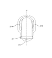
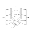
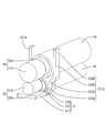
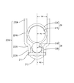
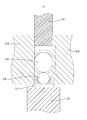
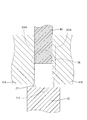
- the perspective view of the electric wire with a terminal concerning one embodiment Front view of electric wire with terminal Terminal perspective view Rear view of terminals Terminal side view
- FIGS. 1 and 2 are a perspective view and a front view of a terminal-attached electric wire 1 according to the present embodiment.
- the terminal-attached electric wire 1 includes a plurality (two in the present embodiment) of electric wires 3A and 3B and a terminal 2 that holds the plurality of electric wires 3A and 3B side by side.
- the upper side in FIG. 1 is the upper side (the lower side is the lower side)
- the left front side is the front or front
- the rear right side is the rear or the rear
- the left rear side is the left (the right front side is the right).
- the electric wires 3A and 3B connected to the terminal 2 are obtained by covering the conductors 31A and 31B with insulating coatings 32A and 32B made of synthetic resin. At the ends of the electric wires 3A and 3B, the insulation coatings 32A and 32B are stripped off, and the conductors 31A and 31B are exposed to form exposed conductors.
- the conductors 31A and 31B are made of a metal material such as aluminum, aluminum alloy, copper, or copper alloy.
- a stranded wire in which a plurality of metal strands are twisted is used, but it may be a single wire.
- the cross-sectional shapes of the electric wires 3A and 3B and the conductors 31A and 31B are substantially circular.
- the electric wires 3A and 3B are different from each other in thickness, and an electric wire having a large thickness is referred to as a first electric wire 3A, and an electric wire having a thickness smaller than that of the first electric wire 3A is referred to as a second electric wire 3B.
- each electric wire 3A, 3B is provided with the conductor from which a thickness dimension mutually differs
- the 1st electric wire 3A is the 1st conductor 31A with a large thickness dimension
- the 2nd electric wire 3B is the 2nd conductor with a small thickness dimension. 31B is provided.
- the radii of the electric wires 3A and 3B are R A and R B
- the radii of the conductors 31A and 31B are R a and R b (FIG. 7). That is, R A > R a and R B > R b , and R A ⁇ R B and R a ⁇ R b .
- Each conductor 31A but it is not limited thickness of 31B, for example, R a and about 4.0 mm ⁇ 6.0 mm, a R b may be about 1.5 mm ⁇ 3.5 mm.
- the first electric wire 3A is connected and held on the terminal 2 so that the first electric wire 3A is arranged at a higher position than the second electric wire.
- the terminal 2 includes a base portion 21 and a holding portion 22, and is formed of a metal material such as copper, copper alloy, aluminum, or aluminum alloy.
- a metal material such as copper, copper alloy, aluminum, or aluminum alloy.
- the surface of the metal material which comprises the terminal 2 may be plated as needed.
- the base portion 21 of the present embodiment includes a flat plate-like connecting portion 211, an inclined portion 212 connected to the rear of the connecting portion 211, and an electric wire receiving portion 213 connected to the rear of the inclined portion 212.
- the upper surface (mounting surface) of the connection portion 211 having a substantially square shape when viewed from above is formed in a flat horizontal plane.
- the second conductor 31B is mounted on the connection portion 211, and this The first conductor 31A is placed on and connected to the two conductors 31B.
- the upper surface of the electric wire receiving portion 213 is formed in a curved shape along the outer periphery of the second electric wire 3B, and is supported in a state where the second electric wire 3B is fitted to this curved surface (FIG.
- the upper surface of the inclined portion 212 is formed in such a shape that both surfaces are smoothly continuous while being inclined downward from the upper surface of the connecting portion 211 toward the upper surface of the wire receiving portion 213. For this reason, stress concentration in the exposed conductor portion can be avoided during manufacture and use of the electric wire 1 with a terminal.
- the holding part 22 has a left holding piece 221A that extends upward from the left side of the wire receiving part 213 and a right holding piece 221B that also extends from the right side.
- the holding pieces 221A and 221B are formed substantially symmetrically with respect to the vertical plane ⁇ that passes through the left and right centers of the rear end of the connecting portion 211 and is parallel to the direction in which the electric wires 3A and 3B are led out.
- Step portions 222A and 222B are provided.
- the step portion 222A, 222B, the height of the center upper surface of the wire receiving portion 213 at a position lower than the higher (2R B + R A) than R B, are provided ( Figure 4).
- proximal end 223A is assumed substantially equal to the radius R B of the second wire 3B, the step portion upward In the separation portions 224A and 224B that are separated from each other via 222A and 222B, they are substantially equal to the radius RA of the first electric wire 3A (FIG. 4).
- the extending ends of the holding pieces 221A and 221B are referred to as tip portions 225A and 225B.
- extension length of the left holding piece 221A and the right holding piece 221B is a length that substantially goes around the outer circumference of the two electric wires 3A and 3B held between them together with the left and right widths of the electric wire receiving portion 213. It is said.
- wire with terminal 1 As shown in FIG. 1 and FIG. 2, in the electric wire with terminal 1 according to the present embodiment, a plurality of electric wires 3 ⁇ / b> A and 3 ⁇ / b> B are held on the terminal 2 in a vertically arranged manner, and each of the electric wires 3 ⁇ / b> A and 3 ⁇ / b> B
- the conductors 31 ⁇ / b> A and 31 ⁇ / b> B exposed at the terminal are integrated by welding or the like so as to form a substantially rectangular parallelepiped shape in this embodiment, and are evenly connected to the upper surface of the connection portion 211.
- the compressibility of each of the conductors 31A and 31B (100 ⁇ the cross-sectional area of the conductor after welding / the cross-sectional area of the conductor before welding) in the connection portion with the connection portion 211 is preferably 80% to 110%. Moreover, the one where the difference of the compression rate of each conductor 31A, 31B is smaller is preferable.
- the plurality of electric wires 3A and 3B are arranged such that the first electric wire 3A is higher than the second electric wire 3B.
- the plurality of electric wires 3A and 3B are arranged in the center of the conductors 31A and 31B in one vertical plane ⁇ that is perpendicular to the flat mounting surface of the connecting portion 211 and parallel to the extending direction of the electric wires 3A and 3B. Are held in a vertically aligned manner.
- the second electric wire 3B is fitted into the curved surface on the upper surface of the electric wire receiving portion 213, and the base end portions 223A and 223B of the holding pieces 221A and 221B are supported in contact from both the left and right sides.
- the electric wire 3A is placed immediately above the electric wire 3B, and is supported by the separation portions 224A and 224B of the holding pieces 221A and 221B coming into contact from both the left and right sides.
- the end portions 225A and 225B of the holding pieces 221A and 221B are crimped so as to wrap around the upper surface of the outer periphery of the electric wire 3A arranged above, and the holding pieces 221A and 221B are caulked to thereby form a plurality of electric wires 3A.
- 3B is firmly fixed on the terminal 2.
- the terminal 2 and each electric wire 3A, 3B are prepared.
- the terminal 2 of the present embodiment is formed by welding, for example, a first member obtained by deforming a part of a flat metal plate material by punching or the like, and a second member obtained by bending a band-shaped metal bar material into a substantially U shape. To form the shapes shown in FIGS. 3 to 5.
- the flat plate portion constitutes the connecting portion 211
- the deformed portion constitutes the inclined portion 212.
- the second member constitutes the left holding piece 221A, the wire receiving portion 213, and the right holding piece 221B in this order from the end.
- each of the electric wires 3A and 3B peels and removes the insulating coatings 32A and 32B at the terminals to expose the conductors 31A and 31B.
- the electric wires 3 ⁇ / b> A and 3 ⁇ / b> B are placed on the terminal 2.
- the 2nd electric wire 3B is mounted on the base part 21.
- the portion provided with the insulating coating 32B is placed on the wire receiving portion 213, the exposed second conductor 31B is led out slightly upward along the inclined portion 212, and this end is connected to the connecting portion 211.
- the first electric wire 3A is placed on the second electric wire 3B.
- the end portion of the insulating coating 32A is aligned with the end portion of the insulating coating 32B of the electric wire 3B, the exposed conductor 31A is led out slightly downward so as to contact the conductor 31B, and this end is connected to the connecting portion 211. Is disposed so as to be aligned with the end of the conductor 31B.
- the electric wires 3A and 3B are sandwiched between the holding pieces 221A and 221B formed so as to form a predetermined interval between the opposing surfaces in a state where the left and right sides are in contact with each other.
- the center of 31A, 31B is supported in the aspect arranged up and down (FIG. 7).
- connection portion 211 of the terminal 2 on which the electric wires 3A and 3B are placed is set on a welding jig, and the conductors 31A and 31B are integrated by ultrasonic welding. While connecting to the connection portion 211 of the terminal 2 (connection process).
- welding jigs shape holding jigs 41A and 41B that have a vertical surface and hold the shape of the conductor after welding are used, and on the connection part 211 in front of the holding pieces 221A and 221B and the wire receiving part 213.
- the exposed conductors 31 ⁇ / b> A and 31 ⁇ / b> B placed on the left and right sides are arranged so as to be sandwiched between vertical surfaces.
- the connection part 211 is provided on the upper surface (horizontal plane) of the lower pressurization jig 42.
- Ultrasonic welding is performed by pushing down the upper pressurizing jig 43 having a horizontal surface from above the conductors 31A, 31B (electric wires 3A, 3B) and applying ultrasonic vibration while applying pressure along the vertical plane ⁇ . (FIG. 8).
- the conductors 31A and 31B are integrated to form a substantially rectangular parallelepiped shape and are evenly connected to the connection portion 211 (FIG. 9).
- the holding pieces 221A and 221B are crimped to the electric wires 3A and 3B.
- the end portions 225A and 225B of the holding pieces 221A and 221B are crimped so as to be wound around the upper surface of the outer periphery of the electric wire 3A, and the electric wires 3A and 3B are crimped by the holding pieces 221A and 221B.
- the terminal-attached electric wire 1 shown in FIG. 1 is obtained in which two electric wires 3A and 3B having different thickness dimensions are arranged and held in the vertical direction.
- the electric wire with terminal 1 in which the electric wires 3A and 3B are arranged in the vertical direction and connected to the terminal 2 can be obtained.
- the holding pieces 221A and 221B of the terminal 2 pass through the left and right centers of the rear end of the connecting portion 211 and have a distance from the vertical plane ⁇ parallel to the extending direction of the electric wires 3A and 3B. It is formed to be equal at the same height.
- the conductors 31A and 31B are evenly connected to the base portion 21 in an integrated state, and the peel strength is improved as compared with the conventional electric wire with terminal. .
- the design of the terminal 2 can be easily changed so that a plurality of electric wires with various thicknesses and numbers can be held.
- one strip-shaped metal bar material in which the left holding piece 221A and the right holding piece 221B constituting the holding portion 22 are connected via the electric wire receiving portion 213 constituting a part of the base portion 21. (Second member) is formed by bending. Therefore, the distance between the opposing surfaces of the left holding piece 221A and the right holding piece 221B, the extension length thereof, and the left and right widths of the wire receiving portion 213 can be easily adjusted according to the thickness dimensions of the plurality of electric wires. can do.
- the first member can be used in common regardless of the thickness dimensions of the plurality of electric wires, while various thickness dimensions can be obtained only by adjusting the length of the second member and the bending interval.
- maintain the some electric wire provided with equally can be obtained.
- the two electric wires 3A and 3B having different thickness dimensions of the conductors 31A and 31B can be evenly connected to the connection portion 211. Since the conductors 31A and 31B are integrated and evenly connected to the connection portion 211, not only the electric wire 3B arranged below but also the peeling strength of the electric wire 3A arranged above is improved. In particular, since the conductor 31B having a small thickness is integrally connected so as to be wrapped under the conductor 31A having a large thickness, the peel strength of the thin second electric wire 3B can be significantly increased. it can. As a result, in the electric wire with terminal 1 of the present embodiment, high connection reliability is realized as a whole.
- the end portions 225A and 225B of the holding pieces 221A and 221B are crimped to the upper surface of the outer periphery of the electric wire 3A, and the electric wires 3A and 3B are crimped onto the terminal 2 by the holding pieces 221A and 221B. Yes.
- the peel strength is further improved despite the simple configuration.
- the terminal-attached electric wire 1 in which the two electric wires 3A and 3B are connected to the terminal 2 is shown, but three or more electric wires may be connected.
- the two electric wires 3A and 3B connected to the terminal 2 are different from each other in the thickness dimension of the conductor and the electric wire. Good.
- the stepped portions 222A and 222B may not be formed on the holding pieces 221A and 221B.
- the left holding piece 221A and the right holding piece 221B constituting the holding unit 22 have a symmetrical shape with respect to the vertical plane ⁇ and are arranged symmetrically.
- the present invention is not limited to this.
- either one of the extension lengths may be slightly longer than the other, and the upper surface of the electric wire disposed at the uppermost portion across the vertical plane ⁇ may be crimped.
- the base end portions of the holding pieces may be partially overlapped and slightly shifted in the front-rear direction so that the centers of the conductors included in the electric wires are reliably arranged on the vertical plane ⁇ .
- the base portion 21 of the terminal 2 is provided with the flat connection portion 211, but is not limited thereto.
- the mounting surface of the pedestal part may be formed in a curved surface shape along the outer periphery of the electric wire mounted thereon.
- the connection part 211 of this embodiment makes a top view substantially square shape, it is not limited to this.
- the terminal 2 may have a structure such as a tab extending from the connection portion, and may be connected to an electric wire or the like different from each electric wire placed on the connection portion 211.
- the base portion 21 has a symmetrical shape.
- the holding pieces 221A and 221B are formed by bending and deforming the strip-shaped metal bar to form the step portions 222A and 222B.
- the present invention is not limited to such a configuration.
- the stepped portion may be formed by changing the thickness by extending the tip of the holding piece.
- the holding piece is not formed with a stepped portion, and is extended obliquely upward from the base part or is smoothly deformed by a curved surface, so that the width between the holding pieces is wider on the upper side than on the lower side. You may form as follows.
- the welding method is not limited to ultrasonic welding, Another welding methods, such as resistance welding, may be sufficient. .
- Terminal 21 Base portion 22: Holding portion 221A: Left holding piece 221B: Right holding piece 222A, 222B: Stepped portion 223A, 223B: Base end portion 224A, 224B: Separating portion 3A: First electric wire 3B: second electric wire 31A: first conductor 31B: second conductor
Landscapes
- Engineering & Computer Science (AREA)
- Manufacturing & Machinery (AREA)
- Connections Effected By Soldering, Adhesion, Or Permanent Deformation (AREA)
- Manufacturing Of Electrical Connectors (AREA)
Abstract
導体(31A、31B)の周囲を覆う絶縁被覆(32A、32B)の端部から前記導体(31A、31B)が露出した露出導体を備える複数の電線(3A、3B)を上下に並べて接続保持する端子(2)を、前記複数の電線(3A、3B)を載置して前記露出導体と接続される台部(21)と、前記台部(21)上に載置された前記複数の電線(3A、3B)を上下に並べて保持 する保持部(22)と、を有するものとする。前記保持部(22)は前記台部(21)の左右両側からそれぞれ上方に延出する左保持片(221A)および右保持片(221B)を備え、前記左保持片(221A)および前記右保持片(221B)で、前記複数の電線(3A、3B)を左右両側から保持する。
Description
本明細書によって開示される技術は、端子、端子付き電線および端子付き電線の製造方法に関する。
従来、自動車等の配線において、1つの端子に複数の電線を接続してなる端子付き電線が用いられている。このような端子付き電線として、例えば特許文献1に記載のものなどが知られている。
特許文献1に記載の端子付き電線は、複数の電線を、接続部上に横並びに配置して接続したものであり、接続部を段差状に形成することで、導体の太さ寸法が異なる電線を均等に接続可能としている。
ところで、端子付き電線は、様々な環境下で使用される。設置スペース上の制約や電線の配策方向等の諸条件によっては、複数の電線を上下縦並びに配置接続した端子の使用が望ましい場合があり、このような端子付き電線が希求されている。
一方で、端子付き電線の設置や使用に際しては、端子に接続された電線に様々な力が作用する事態が想定される。このため、電線と端子との接続を安定した条件下で行い、電線と端子とを均等に接続して、電線の接続信頼性を確保することが望ましい。特に、端子に接続された複数の電線を接続部の上方へと付勢する力、すなわち接続部から引き剥がそうとする力に対しては、十分な対抗力(引き剥がし強さ)を備えていることが好ましい。
一方で、端子付き電線の設置や使用に際しては、端子に接続された電線に様々な力が作用する事態が想定される。このため、電線と端子との接続を安定した条件下で行い、電線と端子とを均等に接続して、電線の接続信頼性を確保することが望ましい。特に、端子に接続された複数の電線を接続部の上方へと付勢する力、すなわち接続部から引き剥がそうとする力に対しては、十分な対抗力(引き剥がし強さ)を備えていることが好ましい。
以下、本明細書において「均等に接続する」とは、接続部分における導体中に明らかに他とは異質な部分が形成されることがないように、接続を行うことを意味する。上記のような異質な部分が形成される原因として、接続工程において印加する圧力が導体全体に均等に伝わらず、受ける圧力が小さ過ぎる部分や、大き過ぎる部分が局所的に生じて、導体が部分的に良好に溶融しなかったり、劣化したりすること等が考えられる。
本明細書は、上記事情に鑑み、複数の電線を上下縦並びに配置して接続した端子付き電線であって、電線の接続信頼性に優れた端子付き電線を提供する技術を開示する。
本明細書が開示する端子は、導体の周囲を覆う絶縁被覆の端部から前記導体が露出した露出導体を備える複数の電線を、上下に並べて接続保持する端子であって、前記複数の電線を載置して前記露出導体と接続される台部と、前記台部上に載置された前記複数の電線を上下に並べて保持する保持部と、を有する。前記保持部は、前記台部の左右両側からそれぞれ上方に延出する左保持片および右保持片を備え、前記左保持片および前記右保持片で前記複数の電線を左右両側から保持する。
上記構成によれば、複数の電線を上下縦並びに配置接続する端子であって、電線の接続信頼性に優れた端子付き電線を提供可能な端子を得ることができる。すなわち、台部上に載置された複数の電線を左右両側から支持する左保持片および右保持片間の幅を、接続保持される電線の太さ寸法に合わせて適切に調整することにより、複数の電線を、左右にずれないよう台部上に支持できる。よって、この状態で電線と端子との接続を行えば、安定した条件下で電線と端子との接続を実行できるので、接続信頼性の高い端子付き電線を得られる。また、端子が、台部上に載置された複数の電線を支持する構造を有するので、溶接時に電線を支持するための治具を別途設ける必要もない。
また、本明細書は、導体の周囲を覆う絶縁被覆の端部から前記導体が露出した露出導体を備える複数の電線と、前記複数の電線を上下に並べて接続保持する端子と、を有する端子付き電線であって、前記端子は、前記複数の電線を載置して前記露出導体と接続された台部と、前記台部上に載置された前記複数の電線を上下に並べて保持する保持部と、を有し、前記保持部は、高い位置に配される電線が低い位置に配される電線以上の太さ寸法を有するように前記複数の電線を左右両側から保持している端子付き電線を開示する。
さらに、本明細書は、導体の周囲を覆う絶縁被覆の端部から前記導体が露出した露出導体を備える複数の電線と、台部および保持部を備えて前記複数の電線を接続保持する端子と、を有する端子付き電線の製造方法であって、前記複数の電線を、高い位置に配される電線が低い位置に配される電線以上の太さ寸法を有するように前記台部上に載置して、左右両側から前記保持部で支持する載置工程を実行した後に、前記露出導体と前記台部を上下から挟んで加圧しつつ接続する接続工程を実行する端子付き電線の製造方法を開示する。
上記構成によれば、複数の電線を上下縦並びに配置接続した端子付き電線であって、電線の接続信頼性に優れた端子付き電線を得ることができる。すなわち、上記構成によれば、複数の電線は、左右にずれることがないように、保持部によって左右両側から支持される。よって、電線と端子との接続を、安定した条件下で行うことができるので、接続信頼性の高い端子付き電線を得られる。また、複数の電線は、前記保持部によって左右両側から支持されるので、溶接時に電線を支持するための治具を別途設ける必要もない。
また、上記構成によれば、従来のものと比べて、特に電線の引き剥がし強さが向上した端子付き電線を得ることができる。すなわち、上記構成に係る端子付き電線では、複数の電線が、端子の台部に上下縦並びに配置された態様で接続されるため、複数の電線のうち下方に配される電線が、上方に配される電線で押さえ付けられるだけでなく、上方に配される電線も下方の電線と導体が一体化した状態で接続されて、単独で台部に接続された場合と比較して引き剥がし強さが向上する。
さらに、上記端子付き電線および端子付き電線の製造方法によれば、導体の太さ寸法が小さく引き剥がし強さに劣る細い電線の導体ほど低い位置に配されて、上方に配される太い電線の太さ寸法が大きい導体で包み込まれるように一体化しつつ、台部に接続される。よって、特に細い電線の引き剥がし強さを向上させることができ、全体として高い接続信頼性を確保できる。
本明細書が開示する端子、端子付き電線、および端子付き電線の製造方法では、上記構成に加え、前記保持部が、前記台部の左右両側からそれぞれ上方に向けて延出する左保持片および右保持片を備えており、前記左保持片および前記右保持片の間の幅が、下方側よりも上方側において広くなっており、互いに太さ寸法が異なる複数の電線を接続保持するものとしてもよい。
このような構成によれば、太さ寸法が異なる複数の電線を、端子に均等に接続できる。すなわち、上記構成の端子等では、各高さにおける左保持片および右保持片の間の幅を適切に設定することにより、複数の電線を構成する各電線の太さ寸法が異なる場合でも、全ての電線の左右方向への移動を規制しつつ支持できる。よって、互いに太さ寸法が異なる複数の電線を、安定した条件下で、均等に端子に接続できる。ここで、左保持片および右保持片の間の幅は、下方側よりも上方側において広くなっているので、各電線のうち太さ寸法の大きい電線が上方に配されることとなり、上述のように、特に細い電線の引き剥がし強さが向上して、全体として高い接続信頼性を確保できる。
本明細書が開示する端子付き電線、および端子付き電線の製造方法では、上記構成に加え、前記保持部が、前記複数の電線の絶縁被覆に圧着しているように構成してもよい。
このような構成によれば、保持部が絶縁被覆に圧着していることで、複数の電線が外周を抱え込まれるように端子上に保持される。よって、引き剥がしに対する接続信頼性を一層高めることができる。ここで、保持部が、電線を保持する機能と、電線を加締める機能を兼備する構成となっているため、電線を加締めるための部材を別途設けることなく、簡便な構造で接続を強固なものとすることができる。また、保持部は、露出導体ではなく絶縁被覆に圧着しているため、接続工程を実施する際に保持部が障害となったり、圧着した保持部が導体を損傷して接続信頼性を低下させたりする虞もない。
本明細書が開示する技術によれば、複数の電線を上下縦並びに配置して接続した端子付き電線であって、電線の接続信頼性に優れた端子付き電線を提供することができる。
以下、好ましい実施形態について、図1から図9を参照しながら説明する。
図1および図2は、本実施形態に係る端子付き電線1の斜視図および正面図である。端子付き電線1は、複数(本実施形態では2本)の電線3A、3Bと、複数の電線3A、3Bを上下に並べて接続保持する端子2と、を有する。
なお、以下の説明では、図1における上側を上(下側を下)、左手前側を前または正面(右奥側を後または背面)、左奥側を左(右手前側を右)とする。
図1および図2は、本実施形態に係る端子付き電線1の斜視図および正面図である。端子付き電線1は、複数(本実施形態では2本)の電線3A、3Bと、複数の電線3A、3Bを上下に並べて接続保持する端子2と、を有する。
なお、以下の説明では、図1における上側を上(下側を下)、左手前側を前または正面(右奥側を後または背面)、左奥側を左(右手前側を右)とする。
(電線3A、3B)
端子2に接続される電線3A、3Bは、図6および図7に示すように、導体31A、31Bの周囲を、合成樹脂製の絶縁被覆32A、32Bで覆ったものである。各電線3A、3Bの端末においては、絶縁被覆32A、32Bが剥ぎ取られ、導体31A、31Bが露出されて、露出導体が形成されている。
端子2に接続される電線3A、3Bは、図6および図7に示すように、導体31A、31Bの周囲を、合成樹脂製の絶縁被覆32A、32Bで覆ったものである。各電線3A、3Bの端末においては、絶縁被覆32A、32Bが剥ぎ取られ、導体31A、31Bが露出されて、露出導体が形成されている。
導体31A、31Bは、アルミニウム、アルミニウム合金、銅、銅合金等の金属材料からなる。本実施形態においては、導体31A、31Bとして、複数の金属素線が撚り合わされた撚り線を使用しているが、単線からなるものであってもよい。
各電線3A、3Bおよび各導体31A、31Bの断面形状は、略円形状である。電線3A、3Bは、互いに太さ寸法が相違しており、太さ寸法が大きい電線を第1電線3Aとし、第1電線3Aよりも太さ寸法が小さい電線を第2電線3Bとする。また、各電線3A、3Bは、互いに太さ寸法の異なる導体を備えており、第1電線3Aが太さ寸法の大きい第1導体31Aを、第2電線3Bが太さ寸法の小さい第2導体31Bを、備えている。
以下、各電線3A、3Bの半径をRA、RB、各導体31A、31Bの半径をRa、Rbとする(図7)。すなわち、RA>RaおよびRB>Rb、かつ、RA≧RBおよびRa≧Rbである。各導体31A、31Bの太さは限定されるものではないが、例えばRaを4.0mm~6.0mm程度、Rbを1.5mm~3.5mm程度とすることができる。
端子付き電線1では、第1電線3Aの方が第2電線よりも高い位置に配されるように、端子2上に接続保持される。
(端子2)
端子2は、図3から図5に示すように、台部21と、保持部22と、を有しており、銅、銅合金、アルミニウム、アルミニウム合金等の金属材から形成されている。なお、端子2を構成する金属材の表面には、必要に応じて、メッキ処理が施されていてもよい。
端子2は、図3から図5に示すように、台部21と、保持部22と、を有しており、銅、銅合金、アルミニウム、アルミニウム合金等の金属材から形成されている。なお、端子2を構成する金属材の表面には、必要に応じて、メッキ処理が施されていてもよい。
本実施形態の台部21は、平板状の接続部211と、この接続部211後方に連なる傾斜部212と、さらに傾斜部212の後方に連なる電線受部213と、を有する。上面視略正方形をなす接続部211の上面(載置面)は、フラットな水平面に形成されており、後述するように、この接続部211上に第2導体31Bが載置され、さらにこの第2導体31B上に第1導体31Aが載置されて、接続される。電線受部213の上面は、第2電線3Bの外周に沿う曲面状に形成されており、この曲面に第2電線3Bが嵌合した状態で支持される(図4)。これにより、第2電線3Bの位置ずれを、効果的に規制できるものとなっている。また、傾斜部212の上面は、接続部211の上面から電線受部213の上面に向けて下向きに傾斜しつつ、両面を滑らかに連続させるような形状に形成されている。このため、端子付き電線1の製造時および使用時において、露出導体部分における応力集中を回避できるものとなっている。
保持部22は、電線受部213の左側部から上方に向けて延出する左保持片221Aと、同じく右側部から延出する右保持片221Bと、を有している。本実施形態では、保持片221A、221Bは、接続部211後端の左右中心を通り、電線3A、3Bを導出させる方向に平行な垂直面αに対し、ほぼ対称に形成されており、それぞれに段差部222A、222Bが設けられている。なお、段差部222A、222Bは、電線受部213の中央上面からの高さが、RBよりも高く(2RB+RA)よりも低い位置に、設けられている(図4)。
左保持片221Aおよび右保持片221Bの対向面から垂直面αまでの距離は、基端部223A、223Bでは、第2電線3Bの半径RBとほぼ等しいものとされ、上方に向けて段差部222A、222Bを経て互いに離隔した離隔部224A、224Bでは、第1電線3Aの半径RAとほぼ等しいものとされている(図4)。なお、保持片221A、221Bの延出端を、先端部225A、225Bとする。
また、左保持片221Aおよび右保持片221Bの延出長は、電線受部213の左右幅と併せて、これらの間に保持する2本の電線3A、3Bを束ねた外周をほぼ一周する長さとされている。
また、左保持片221Aおよび右保持片221Bの延出長は、電線受部213の左右幅と併せて、これらの間に保持する2本の電線3A、3Bを束ねた外周をほぼ一周する長さとされている。
(端子付き電線1)
図1および図2に示すように、本実施形態に係る端子付き電線1では、複数の電線3A、3Bが、上下に並んだ態様で端子2上に保持されるとともに、各電線3A、3Bの端末において露出された各導体31A、31Bが、本実施形態では概ね直方体の形状をなすように溶接等によって一体化され、接続部211の上面に均等に接続されている。なお、接続部211との接続部分における各導体31A、31Bの圧縮率(100×溶接後の導体の断面積/溶接前の導体の断面積)は、80%~110%であるのが好ましい。また、各導体31A、31Bの圧縮率の差は、小さい方が好ましい。
図1および図2に示すように、本実施形態に係る端子付き電線1では、複数の電線3A、3Bが、上下に並んだ態様で端子2上に保持されるとともに、各電線3A、3Bの端末において露出された各導体31A、31Bが、本実施形態では概ね直方体の形状をなすように溶接等によって一体化され、接続部211の上面に均等に接続されている。なお、接続部211との接続部分における各導体31A、31Bの圧縮率(100×溶接後の導体の断面積/溶接前の導体の断面積)は、80%~110%であるのが好ましい。また、各導体31A、31Bの圧縮率の差は、小さい方が好ましい。
ここで、上述のように、複数の電線3A、3Bは、第1電線3Aの方が第2電線3Bよりも高い位置に配される。また、複数の電線3A、3Bは、接続部211のフラットに形成された載置面に垂直かつ電線3A、3Bの延出方向に平行な一の垂直面α内に、導体31A、31Bの中心が上下に並んだ態様で保持される。
具体的には、第2電線3Bは、電線受部213上面の曲面内に嵌めこまれるとともに、保持片221A、221Bの基端部223A、223Bが左右両側から当接して支持される。一方、電線3Aは、電線3Bの真上に載置されて、保持片221A、221Bの離隔部224A、224Bが左右両側から当接することによって支持される。
さらに、保持片221A、221Bの先端部225A、225Bが、上方に配された電線3Aの外周上面に巻き付くように圧着しており、保持片221A、221Bを加締めることで、複数の電線3A、3Bが端子2上にしっかりと固定される。
続いて、本実施形態の端子付き電線1の製造方法について説明する。
まず、端子2および各電線3A、3Bを準備する。
本実施形態の端子2は、平板状の金属板材の一部を叩き出し等により変形加工した第1部材と、帯状の金属棒材を略U型に曲げ成形した第2部材とを、溶接等により接続して、図3から図5に示す形状をなすように形成する。なお、第1部材のうち、平板状の部分が接続部211を、変形加工部分が傾斜部212を、それぞれ構成する。一方、第2部材は、端から順に、左保持片221A、電線受部213、右保持片221Bを構成する。
また、各電線3A、3Bは、端末において絶縁被覆32A、32Bを剥離除去して、導体31A、31Bを露出させておく。
まず、端子2および各電線3A、3Bを準備する。
本実施形態の端子2は、平板状の金属板材の一部を叩き出し等により変形加工した第1部材と、帯状の金属棒材を略U型に曲げ成形した第2部材とを、溶接等により接続して、図3から図5に示す形状をなすように形成する。なお、第1部材のうち、平板状の部分が接続部211を、変形加工部分が傾斜部212を、それぞれ構成する。一方、第2部材は、端から順に、左保持片221A、電線受部213、右保持片221Bを構成する。
また、各電線3A、3Bは、端末において絶縁被覆32A、32Bを剥離除去して、導体31A、31Bを露出させておく。
次に、図6および図7に示すように、端子2上に各電線3A、3Bを載置する。
最初に、台部21上に、第2電線3Bを載置する。詳しくは、絶縁被覆32Bを備えた部分を電線受部213上に載せ、露出させた第2導体31Bを傾斜部212に沿わせながらやや上方に向けて導出して、この末端を接続部211上に配置する。次いで、第2電線3B上に、第1電線3Aを載置する。詳しくは、絶縁被覆32Aの端部を電線3Bの絶縁被覆32Bの端部に揃え、露出させた導体31Aを導体31Bと当接するようにやや下方に向けて導出して、この末端を接続部211の上方において導体31Bの末端と揃えるように配置する。これにより、対向面間が所定の間隔をなすように形成された保持片221A、221Bに、各電線3A、3Bが左右両側を当接させた状態で挟持され、垂直面α内において、各導体31A、31Bの中心が上下に並んだ態様で支持される(図7)。
最初に、台部21上に、第2電線3Bを載置する。詳しくは、絶縁被覆32Bを備えた部分を電線受部213上に載せ、露出させた第2導体31Bを傾斜部212に沿わせながらやや上方に向けて導出して、この末端を接続部211上に配置する。次いで、第2電線3B上に、第1電線3Aを載置する。詳しくは、絶縁被覆32Aの端部を電線3Bの絶縁被覆32Bの端部に揃え、露出させた導体31Aを導体31Bと当接するようにやや下方に向けて導出して、この末端を接続部211の上方において導体31Bの末端と揃えるように配置する。これにより、対向面間が所定の間隔をなすように形成された保持片221A、221Bに、各電線3A、3Bが左右両側を当接させた状態で挟持され、垂直面α内において、各導体31A、31Bの中心が上下に並んだ態様で支持される(図7)。
次に、各電線3A、3Bの導体31A、31Bと、端子2の台部21を、溶接する。
図8および図9に示すように、各電線3A、3Bを載置した端子2の接続部211を、溶接用の治具にセットして、超音波溶接により各導体31A、31Bを一体化させつつ端子2の接続部211に接続する(接続工程)。溶接用の治具としては、垂直面を備えて溶接後の導体の形状を保持する形状保持治具41A、41Bを使用し、保持片221A、221Bおよび電線受部213の前方において接続部211上に載置された露出導体31A、31Bを、左右両側から垂直面で挟むように配置する。そして、同じく溶接用の治具として、露出導体31A、31Bおよび接続部211を上下から挟んで使用する加圧治具のうち、下側加圧治具42の上面(水平面)に接続部211を載せ、導体31A、31B(電線3A、3B)の上方から水平面を備えた上側加圧治具43を押し下げて、垂直面αに沿って圧力をかけながら超音波振動を加えることにより、超音波溶接を行う(図8)。これにより、導体31A、31Bが一体化し概ね直方体の形状をなして接続部211と均等に接続される(図9)。
図8および図9に示すように、各電線3A、3Bを載置した端子2の接続部211を、溶接用の治具にセットして、超音波溶接により各導体31A、31Bを一体化させつつ端子2の接続部211に接続する(接続工程)。溶接用の治具としては、垂直面を備えて溶接後の導体の形状を保持する形状保持治具41A、41Bを使用し、保持片221A、221Bおよび電線受部213の前方において接続部211上に載置された露出導体31A、31Bを、左右両側から垂直面で挟むように配置する。そして、同じく溶接用の治具として、露出導体31A、31Bおよび接続部211を上下から挟んで使用する加圧治具のうち、下側加圧治具42の上面(水平面)に接続部211を載せ、導体31A、31B(電線3A、3B)の上方から水平面を備えた上側加圧治具43を押し下げて、垂直面αに沿って圧力をかけながら超音波振動を加えることにより、超音波溶接を行う(図8)。これにより、導体31A、31Bが一体化し概ね直方体の形状をなして接続部211と均等に接続される(図9)。
最後に、保持片221A、221Bを、各電線3A、3Bに圧着する。
超音波溶接が終了した後、保持片221A、221Bの先端部225A、225Bを電線3Aの外周上面に巻き付けるように圧着し、保持片221A、221Bによって各電線3A、3Bを加締める。この結果、太さ寸法の相違する2本の電線3A、3Bを上下に並べて接続保持した、図1に示す端子付き電線1が得られる。
超音波溶接が終了した後、保持片221A、221Bの先端部225A、225Bを電線3Aの外周上面に巻き付けるように圧着し、保持片221A、221Bによって各電線3A、3Bを加締める。この結果、太さ寸法の相違する2本の電線3A、3Bを上下に並べて接続保持した、図1に示す端子付き電線1が得られる。
続いて、本実施形態の作用および効果について説明する。
上記実施形態によれば、各電線3A、3Bを上下縦並びにして端子2に配置接続した端子付き電線1を得ることができる。
本実施形態の端子付き電線1において、端子2の保持片221A、221Bは、接続部211後端の左右中心を通りかつ電線3A、3Bの延出方向に平行な垂直面αからの距離が、同じ高さにおいて等しくなるように形成されている。また、保持片221A、221Bは、垂直面αからの距離が、各高さに応じて、挟持する第1電線3Aの半径RAまたは第2電線3Bの半径RBとほぼ等しくなるように形成されているため、各電線3A、3Bは、各導体31A、31Bの中心が一の垂直面α内において上下に並んだ態様で、左右から当接する保持片221A、221Bの間にしっかりと支持される。よって、溶接接続等を行う際に、導体31A、31Bの双方に対し、垂直面αに沿って均等に圧力をかけることが可能である。この結果、本実施形態の端子付き電線1では、導体31A、31Bが、一体化した状態で台部21に均等に接続され、従来の端子付き電線と比べて引き剥がし強さが向上している。
上記実施形態によれば、各電線3A、3Bを上下縦並びにして端子2に配置接続した端子付き電線1を得ることができる。
本実施形態の端子付き電線1において、端子2の保持片221A、221Bは、接続部211後端の左右中心を通りかつ電線3A、3Bの延出方向に平行な垂直面αからの距離が、同じ高さにおいて等しくなるように形成されている。また、保持片221A、221Bは、垂直面αからの距離が、各高さに応じて、挟持する第1電線3Aの半径RAまたは第2電線3Bの半径RBとほぼ等しくなるように形成されているため、各電線3A、3Bは、各導体31A、31Bの中心が一の垂直面α内において上下に並んだ態様で、左右から当接する保持片221A、221Bの間にしっかりと支持される。よって、溶接接続等を行う際に、導体31A、31Bの双方に対し、垂直面αに沿って均等に圧力をかけることが可能である。この結果、本実施形態の端子付き電線1では、導体31A、31Bが、一体化した状態で台部21に均等に接続され、従来の端子付き電線と比べて引き剥がし強さが向上している。
また、本実施形態によれば、端子2を、様々な太さ寸法や数の複数の電線を保持できるように、容易に設計変更できる。本実施形態の端子2では、保持部22を構成する左保持片221Aおよび右保持片221Bを、台部21の一部を構成する電線受部213を介して連結した帯状の1つの金属棒材(第2部材)を曲げ加工して形成している。よって、左保持片221Aと右保持片221Bの対向面同士の間隔、並びに、これらの延出長および電線受部213の左右幅を、複数の電線の太さ寸法等に合わせて、簡単に調整することができる。すなわち、第1部材は、複数の電線の太さ寸法等に関わらず、共通して用いることができる一方、第2部材の長さと曲げ加工の間隔を調整するだけで、様々な太さ寸法等を備えた複数の電線を均等に接続保持可能な端子2を得ることができる。
さらに、本実施形態によれば、導体31A、31Bの太さ寸法が相違する2本の電線3A、3Bを、均等に接続部211に接続することができる。導体31A、31Bが一体化しつつ接続部211に均等に接続されていることで、下方に配される電線3Bのみならず、上方に配される電線3Aの引き剥がし強さも向上する。特に、太さ寸法の小さい導体31Bは、太さ寸法の大きい導体31Aの下方に包み込まれるように一体化して接続されているから、細い第2電線3Bの引き剥がし強さを格段に高めることができる。この結果、本実施形態の端子付き電線1では、全体として高い接続信頼性が実現されている。
また、本実施形態によれば、保持片221A、221Bの先端部225A、225Bが電線3Aの外周上面に圧着して、電線3A、3Bが保持片221A、221Bによって端子2上に加締められている。この結果、本実施形態の端子付き電線1では、簡便な構成にも関わらず、引き剥がし強さが一層向上している。
<他の実施形態>
本発明は上記記述及び図面によって説明した実施形態に限定されるものではなく、例えば次のような実施形態も本発明の技術的範囲に含まれる。
本発明は上記記述及び図面によって説明した実施形態に限定されるものではなく、例えば次のような実施形態も本発明の技術的範囲に含まれる。
(1)上記実施形態では、端子2に、2本の電線3A、3Bが接続された端子付き電線1を示したが、3本以上の電線が接続されるものでもよい。また、上記実施形態では、端子2に接続される2本の電線3A、3Bを、導体および電線の太さ寸法が互いに異なるものとしたが、各電線の太さ寸法が等しいものであってもよい。電線の太さ寸法が等しい場合、保持片221A、221Bには、段差部222A、222Bを形成しなくともよい。
(2)上記実施形態では、保持部22を構成する左保持片221Aと、右保持片221Bとが、垂直面αに対して対称な形状を有し、かつ、対称に配置されるものとしたが、これに限定されるものではない。例えば、何れか一方の延出長を他方よりもやや長くして、垂直面αを跨いで最上部に配される電線の上面を圧着するようにしてもよい。また、各保持片の基端部を一部重畳させつつ、前後方向に若干ずらして配置して、各電線が備える各導体の中心を垂直面α上に確実に配列させるようにしてもよい。
(3)上記実施形態では、端子2の台部21が、平板状の接続部211を備えるものとしたが、これに限定されるものではない。例えば、台部の載置面が、この上に載置される電線の外周に沿うような曲面状に形成されていてもよい。また、本実施形態の接続部211は、上面視略正方形をなすものであるが、これに限定されるものではない。また、端子2は、接続部から延出するタブ等の構造を備え、接続部211上に載置される各電線とは別の電線等と接続できるものとしてもよい。なお、複数の電線の導体を、中心が同一の垂直面内に上下に並んだ態様で保持することを考えれば、台部21が左右対称形をなすことが好ましい。
(4)上記実施形態では、保持片221A、221Bとして、帯状の金属棒材を曲げ変形して段差部222A、222Bを形成したものを用いたが、このような構成に限定されるものではない。例えば、保持片の先端部を敲き延ばす等して、厚みを変えることにより、段差部を形成してもよい。また、保持片には段差部を形成せず、台部から斜め上方に延出させたり、曲面により滑らかに変形させたりして、下方側よりも上方側において保持片の間の幅が広くなるように形成してもよい。
(5)上記実施形態では、超音波溶接により導体31A、31Bと端子2とを接続する構成を示したが、溶接方法は超音波溶接に限定されず、抵抗溶接等の別の溶接方法でもよい。
1:端子付き電線
2:端子
21:台部
22:保持部
221A:左保持片
221B:右保持片
222A、222B:段差部
223A、223B:基端部
224A、224B:離隔部
3A:第1電線
3B:第2電線
31A:第1導体
31B:第2導体
2:端子
21:台部
22:保持部
221A:左保持片
221B:右保持片
222A、222B:段差部
223A、223B:基端部
224A、224B:離隔部
3A:第1電線
3B:第2電線
31A:第1導体
31B:第2導体
Claims (8)
- 導体の周囲を覆う絶縁被覆の端部から前記導体が露出した露出導体を備える複数の電線を、上下に並べて接続保持する端子であって、
前記複数の電線を載置して前記露出導体と接続される台部と、前記台部上に載置された前記複数の電線を上下に並べて保持する保持部と、を有し、
前記保持部は、前記台部の左右両側からそれぞれ上方に延出する左保持片および右保持片を備え、前記左保持片および前記右保持片で前記複数の電線を左右両側から保持する端子。 - 前記複数の電線として、太さ寸法が異なるものを保持する端子であって、
前記左保持片および前記右保持片の間の幅が、下方側よりも上方側において広くなっている請求項1に記載の端子。 - 導体の周囲を覆う絶縁被覆の端部から前記導体が露出した露出導体を備える複数の電線と、前記複数の電線を上下に並べて接続保持する端子と、を有する端子付き電線であって、
前記端子は、前記複数の電線を載置して前記露出導体と接続された台部と、前記台部上に載置された前記複数の電線を上下に並べて保持する保持部と、を有し、
前記保持部は、高い位置に配される電線が低い位置に配される電線以上の太さ寸法を有するように前記複数の電線を左右両側から保持している端子付き電線。 - 前記複数の電線は、互いに太さ寸法が異なるものであって、
前記保持部は、前記台部の左右両側からそれぞれ上方に向けて延出する左保持片および右保持片を備えており、
前記左保持片および前記右保持片の間の幅が、下方側よりも上方側において広くなっている請求項3に記載の端子付き電線。 - 前記保持部が、前記複数の電線の前記絶縁被覆に圧着している請求項3または請求項4に記載の端子付き電線。
- 導体の周囲を覆う絶縁被覆の端部から前記導体が露出した露出導体を備える複数の電線と、台部および保持部を備えて前記複数の電線を接続保持する端子と、を有する端子付き電線の製造方法であって、
前記複数の電線を、高い位置に配される電線が低い位置に配される電線以上の太さ寸法を有するように前記台部上に載置して、左右両側から前記保持部で支持する載置工程を実行した後に、
前記露出導体と前記台部を上下から挟んで、加圧しつつ接続する接続工程を実行する端子付き電線の製造方法。 - 前記複数の電線は、互いに太さ寸法が異なるものであって、
前記保持部は、前記台部の左右両側からそれぞれ上方に向けて延出する左保持片および右保持片を備え、
前記左保持片および前記右保持片間の幅が、下方側よりも上方側において広くなっており、
前記載置工程において、前記複数の電線のうち、低い位置に配される電線よりも大きな太さ寸法を有する電線を高い位置に配する請求項6に記載の端子付き電線の製造方法。 - 前記載置工程を実行した後に、さらに前記保持部を前記複数の電線の前記絶縁被覆に圧着する圧着工程を実行する請求項6または請求項7に記載の端子付き電線の製造方法。
Applications Claiming Priority (2)
| Application Number | Priority Date | Filing Date | Title |
|---|---|---|---|
| JP2015085005A JP2016207338A (ja) | 2015-04-17 | 2015-04-17 | 端子、端子付き電線および端子付き電線の製造方法 |
| JP2015-085005 | 2015-04-17 |
Publications (1)
| Publication Number | Publication Date |
|---|---|
| WO2016167124A1 true WO2016167124A1 (ja) | 2016-10-20 |
Family
ID=57127065
Family Applications (1)
| Application Number | Title | Priority Date | Filing Date |
|---|---|---|---|
| PCT/JP2016/060335 Ceased WO2016167124A1 (ja) | 2015-04-17 | 2016-03-30 | 端子、端子付き電線および端子付き電線の製造方法 |
Country Status (2)
| Country | Link |
|---|---|
| JP (1) | JP2016207338A (ja) |
| WO (1) | WO2016167124A1 (ja) |
Cited By (1)
| Publication number | Priority date | Publication date | Assignee | Title |
|---|---|---|---|---|
| JP2018081867A (ja) * | 2016-11-18 | 2018-05-24 | 矢崎エナジーシステム株式会社 | ユニットケーブル、及び、ユニットケーブルの製造方法 |
Families Citing this family (1)
| Publication number | Priority date | Publication date | Assignee | Title |
|---|---|---|---|---|
| JP7690350B2 (ja) * | 2021-08-17 | 2025-06-10 | 矢崎総業株式会社 | 圧着補助治具及び圧着補助治具を用いた圧着方法 |
Citations (4)
| Publication number | Priority date | Publication date | Assignee | Title |
|---|---|---|---|---|
| JPS56104070U (ja) * | 1980-01-11 | 1981-08-14 | ||
| JPH0584033U (ja) * | 1992-04-16 | 1993-11-12 | 矢崎総業株式会社 | 圧着端子 |
| JP2008060040A (ja) * | 2006-09-04 | 2008-03-13 | Fujikura Ltd | 圧着端子 |
| JP2014220061A (ja) * | 2013-05-07 | 2014-11-20 | 株式会社オートネットワーク技術研究所 | 端子、端子付き電線および端子付き電線の製造方法 |
-
2015
- 2015-04-17 JP JP2015085005A patent/JP2016207338A/ja active Pending
-
2016
- 2016-03-30 WO PCT/JP2016/060335 patent/WO2016167124A1/ja not_active Ceased
Patent Citations (4)
| Publication number | Priority date | Publication date | Assignee | Title |
|---|---|---|---|---|
| JPS56104070U (ja) * | 1980-01-11 | 1981-08-14 | ||
| JPH0584033U (ja) * | 1992-04-16 | 1993-11-12 | 矢崎総業株式会社 | 圧着端子 |
| JP2008060040A (ja) * | 2006-09-04 | 2008-03-13 | Fujikura Ltd | 圧着端子 |
| JP2014220061A (ja) * | 2013-05-07 | 2014-11-20 | 株式会社オートネットワーク技術研究所 | 端子、端子付き電線および端子付き電線の製造方法 |
Cited By (1)
| Publication number | Priority date | Publication date | Assignee | Title |
|---|---|---|---|---|
| JP2018081867A (ja) * | 2016-11-18 | 2018-05-24 | 矢崎エナジーシステム株式会社 | ユニットケーブル、及び、ユニットケーブルの製造方法 |
Also Published As
| Publication number | Publication date |
|---|---|
| JP2016207338A (ja) | 2016-12-08 |
Similar Documents
| Publication | Publication Date | Title |
|---|---|---|
| JP5428789B2 (ja) | 端子金具付き電線及び端子金具付き電線の製造方法 | |
| EP2192601B1 (en) | Wire harness and its manufacturing method | |
| JP6056639B2 (ja) | 端子、端子付き電線および端子付き電線の製造方法 | |
| EP2735057B1 (en) | Electric wire connecting method | |
| JP6954170B2 (ja) | 端子 | |
| JP6574736B2 (ja) | 端子付き電線の製造方法 | |
| US20140311798A1 (en) | Electric wire connection structure and electric wire connection method | |
| US11791599B2 (en) | Electric cable with terminal and method for manufacturing electric cable with terminal | |
| WO2018198894A1 (ja) | 電線の接続構造、およびハーネスの製造方法 | |
| CN109861010A (zh) | 端子连接方法和端子 | |
| JP2015041509A (ja) | 導電路及び電線 | |
| JP5704422B2 (ja) | 端子付き電線 | |
| JP2016207338A (ja) | 端子、端子付き電線および端子付き電線の製造方法 | |
| JP2011090804A (ja) | 端子金具付き電線および端子金具付き電線の製造方法 | |
| JP2014029884A (ja) | 端子金具付き電線及び端子金具付き電線の製造方法 | |
| JP4268006B2 (ja) | アルミ電線への端子圧着構造及び端子付アルミ電線の製造方法 | |
| JP2016110850A (ja) | 端子金具付き電線、及び端子金具付き電線の製造方法 | |
| JP4731396B2 (ja) | 端子及び端子付きアルミ電線 | |
| JP2013137879A (ja) | 端子付き電線およびその製造方法 | |
| JP5757226B2 (ja) | 端子及び端子付き電線 | |
| JP5151936B2 (ja) | 端子金具及びその製造方法 | |
| JP5720955B2 (ja) | 端子の製造方法および連鎖端子 | |
| JP5058773B2 (ja) | 圧着端子の被覆電線への接続構造 | |
| JP5051071B2 (ja) | 端子金具 | |
| JP5842802B2 (ja) | 端子付き電線 |
Legal Events
| Date | Code | Title | Description |
|---|---|---|---|
| 121 | Ep: the epo has been informed by wipo that ep was designated in this application |
Ref document number: 16779915 Country of ref document: EP Kind code of ref document: A1 |
|
| NENP | Non-entry into the national phase |
Ref country code: DE |
|
| 122 | Ep: pct application non-entry in european phase |
Ref document number: 16779915 Country of ref document: EP Kind code of ref document: A1 |