WO2016167046A1 - シーリング補助部材、採光パネル、およびシーリング構造 - Google Patents
シーリング補助部材、採光パネル、およびシーリング構造 Download PDFInfo
- Publication number
- WO2016167046A1 WO2016167046A1 PCT/JP2016/057001 JP2016057001W WO2016167046A1 WO 2016167046 A1 WO2016167046 A1 WO 2016167046A1 JP 2016057001 W JP2016057001 W JP 2016057001W WO 2016167046 A1 WO2016167046 A1 WO 2016167046A1
- Authority
- WO
- WIPO (PCT)
- Prior art keywords
- daylighting
- main surface
- sealing
- sealing auxiliary
- auxiliary member
- Prior art date
- Legal status (The legal status is an assumption and is not a legal conclusion. Google has not performed a legal analysis and makes no representation as to the accuracy of the status listed.)
- Ceased
Links
Images



Classifications
-
- E—FIXED CONSTRUCTIONS
- E04—BUILDING
- E04B—GENERAL BUILDING CONSTRUCTIONS; WALLS, e.g. PARTITIONS; ROOFS; FLOORS; CEILINGS; INSULATION OR OTHER PROTECTION OF BUILDINGS
- E04B2/00—Walls, e.g. partitions, for buildings; Wall construction with regard to insulation; Connections specially adapted to walls
- E04B2/72—Non-load-bearing walls of elements of relatively thin form with respect to the thickness of the wall
-
- E—FIXED CONSTRUCTIONS
- E04—BUILDING
- E04B—GENERAL BUILDING CONSTRUCTIONS; WALLS, e.g. PARTITIONS; ROOFS; FLOORS; CEILINGS; INSULATION OR OTHER PROTECTION OF BUILDINGS
- E04B2/00—Walls, e.g. partitions, for buildings; Wall construction with regard to insulation; Connections specially adapted to walls
- E04B2/88—Curtain walls
-
- E—FIXED CONSTRUCTIONS
- E06—DOORS, WINDOWS, SHUTTERS, OR ROLLER BLINDS IN GENERAL; LADDERS
- E06B—FIXED OR MOVABLE CLOSURES FOR OPENINGS IN BUILDINGS, VEHICLES, FENCES OR LIKE ENCLOSURES IN GENERAL, e.g. DOORS, WINDOWS, BLINDS, GATES
- E06B3/00—Window sashes, door leaves, or like elements for closing wall or like openings; Layout of fixed or moving closures, e.g. windows in wall or like openings; Features of rigidly-mounted outer frames relating to the mounting of wing frames
- E06B3/54—Fixing of glass panes or like plates
-
- E—FIXED CONSTRUCTIONS
- E06—DOORS, WINDOWS, SHUTTERS, OR ROLLER BLINDS IN GENERAL; LADDERS
- E06B—FIXED OR MOVABLE CLOSURES FOR OPENINGS IN BUILDINGS, VEHICLES, FENCES OR LIKE ENCLOSURES IN GENERAL, e.g. DOORS, WINDOWS, BLINDS, GATES
- E06B3/00—Window sashes, door leaves, or like elements for closing wall or like openings; Layout of fixed or moving closures, e.g. windows in wall or like openings; Features of rigidly-mounted outer frames relating to the mounting of wing frames
- E06B3/54—Fixing of glass panes or like plates
- E06B3/56—Fixing of glass panes or like plates by means of putty, cement, or adhesives only
Definitions
- the present invention relates to a sealing auxiliary member, a daylighting panel, and a sealing structure.
- the adhesive force of the sealing material filled between the daylighting members depends on the area of the end face of the daylighting member that comes into contact with the sealing material. For example, when the daylighting member is thinned, there is a problem that the area of the end face of the daylighting member is reduced and the adhesive force of the sealing material is reduced.
- the main object of the present invention is to provide a sealing auxiliary member excellent in the adhesive strength between the daylighting member and the sealing material regardless of the area of the end face of the daylighting member.
- a sealing auxiliary member provided between a plurality of daylighting members including a glass plate or between at least one daylighting member and a peripheral member,
- the daylighting member has a first main surface, a second main surface formed on the opposite side of the first main surface, and an end surface formed between the first main surface and the second main surface.
- the sealing auxiliary member is A first member extending along the first main surface;
- a sealing auxiliary member is provided, comprising: a second member connected to the first member and protruding from the first member to the opposite side of the first main surface.
- a sealing auxiliary member that is excellent in adhesion between the daylighting member and the sealing material.
- FIG. 1 is a cross-sectional view illustrating a sealing structure according to a first embodiment of the present invention.
- the upper side is the outdoor side, and the lower side is the indoor side.
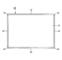
- FIG. 2 is a plan view showing the daylighting panel viewed from the II direction in FIG.
- FIG. 3 is a cross-sectional view showing the daylighting panel viewed from the III direction in FIG.
- the sealing structure has a plurality of daylighting panels 10 and a sealing material 30 as shown in FIG.
- the plurality of daylighting panels 10 are arranged in a plane at intervals. This sealing structure is applied to the outer wall of a building, for example.
- the daylighting panel 10 includes a daylighting member 11, a sealing auxiliary member 12, a joint member 13 (see FIG. 2), and an ultraviolet blocking layer 14.
- the joint member 13 and the ultraviolet blocking layer 14 have an arbitrary configuration, and the daylighting panel 10 may not have the joint member 13 and the ultraviolet blocking layer 14.
- the daylighting member 11 takes in outdoor light such as sunlight into the room.
- the daylighting member 11 includes a glass plate.
- the glass plate is untempered glass or tempered glass.
- the tempered glass may be either heat tempered glass or chemically tempered glass.
- the daylighting member 11 is composed of only one glass plate, but may be composed of a plurality of glass plates.
- the daylighting member 11 may be, for example, laminated glass, multilayer glass, or the like.
- the daylighting member 11 includes a first main surface 111, a second main surface 112 formed on the opposite side of the first main surface 111, the first main surface 111, and the second main surface 112. And an end face 113 formed therebetween.
- the first main surface 111 is arranged on the indoor side, and the second main surface 112 is arranged on the outdoor side.
- the first main surface 111 may be arranged on the outdoor side, and the second main surface 112 may be arranged on the indoor side.
- the first main surface 111 and the second main surface 112 may be curved surfaces as shown in FIG. 3 when viewed from the III direction of FIG.
- the first main surface 111 and the second main surface 112 may be flat surfaces.
- the daylighting member 11 is formed in, for example, a rectangular shape in a plan view, and has a corner at the outer edge.
- the corner may have roundness.
- the sealing auxiliary member 12 is fixed to the outer edge portion of the daylighting member 11 and is in close contact with the sealing material 30. Details of the sealing assisting member 12 will be described later.
- the joint member 13 joins the plurality of sealing auxiliary members 12 at the corners of the outer edge of the daylighting member 11.
- the joint member 13 is fixed to a corner portion of the outer edge portion of the daylighting member 11 and is in close contact with the sealing material 30. Details of the joint member 13 will be described later.
- the ultraviolet blocking layer 14 is formed on the outer edge of the daylighting member 11.
- the ultraviolet blocking layer 14 blocks ultraviolet rays contained in outdoor light such as sunlight. Details of the ultraviolet blocking layer 14 will be described later.
- the sealing material 30 a general building material is used.
- the sealing material 30 is filled and solidified in a liquid state between the plurality of daylighting panels 10 arranged in a planar shape.
- the sealing material 30 may be filled with liquid filling between the daylighting panel 10 and the daylighting panel different from the daylighting panel 10 and may be solidified.
- the daylighting panel different from the daylighting panel 10 include the daylighting panel 10B shown in FIG. 5, the daylighting panel 10C shown in FIG. 6, the daylighting panel 10D shown in FIG.
- the sealing auxiliary member 12 has, for example, a horizontal T-shaped cross section as shown in FIG. 1 and includes a first member 121 and a second member 122.
- the first member 121 extends along the first main surface 111 of the daylighting member 11 and is fixed to the first main surface 111.
- an adhesive is used for fixing. Since the first member 121 extends along the first major surface 111, the posture of the second member 122 is stabilized.
- the second member 122 is connected to the first member 121 and protrudes from the first member 121 to the side opposite to the first main surface 111. Therefore, the sealing material 30 can be filled thicker than the daylighting member 11, and the sealing material 30 can be sufficiently filled. Therefore, the adhesive force between the daylighting member 11 and the sealing material 30 can be improved. This effect becomes more prominent as the daylighting member 11 is thinner.
- the thickness of the lighting member 11 is preferably 3.8 mm or less, more preferably 2.8 mm or less.
- the thickness of the daylighting member 11 is preferably 0.7 mm or more from the viewpoint of handling properties.
- the second member 122 extends along the end surface 113 of the daylighting member 11 and is fixed to the end surface 113.
- this fixing for example, an adhesive is used. Since the sealing assisting member 12 is fixed along two surfaces (the first main surface 111 and the end surface 113) having different orientations of the daylighting member 11, positioning at the time of fixing is easy.
- the second member 122 can protect the end face 113 by extending along the end face 113 of the daylighting member 11.
- the end surface of the glass plate can be protected, and breakage of the glass plate can be reduced. This effect is remarkable when the lighting member 11 is transported after the sealing auxiliary member 12 is attached to the lighting member 11 in a manufacturing factory of the lighting member 11 or the like.
- the second member 122 has a surface 122a that is flush with the second main surface 112 of the daylighting member 11. Therefore, when the building is viewed from the second main surface 112 side (the outdoor side in the present embodiment), the design of the building is not impaired.
- the sealing auxiliary member 12 may be formed of metal or the like, but may be formed of resin or rubber so as to absorb an impact from the outside. As will be described later, the sealing assisting member 12 may be composed of a metal core and a resin or rubber outer skin. When the outer skin is made of resin or rubber, it can absorb external impacts.
- the sealing auxiliary member 12 may have flexibility so that it can be applied to both cases where the first main surface 111 and the second main surface 112 are flat surfaces and curved surfaces. When the first main surface 111 and the second main surface 112 are curved surfaces, the sealing auxiliary member 12 is bent and deformed along the first main surface 111 and the second main surface 112 as shown in FIG.
- the joint member 13 joins the plurality of sealing auxiliary members 12 at the corners of the outer edge of the daylighting member 11 as shown in FIG.
- the joint member 13 is fixed to a corner portion of the outer edge portion of the daylighting member 11 and is in close contact with the sealing material 30.
- the sealing material 30 can be sufficiently filled at the corners of the outer edge of the daylighting member 11.
- the joint member 13 is formed by, for example, injection molding. In this case, injection molding is performed in a state where the daylighting member 11 and the sealing auxiliary member 12 are installed in the mold.
- the joint member 13 may be configured in the same manner as the sealing auxiliary member 12.
- the first member extending along the first main surface 111 of the daylighting member 11 is opposite to the first main surface 111 from the first member.
- a second member protruding to the side is formed by, for example, injection molding. In this case, injection molding is performed in a state where the daylighting member 11 and the sealing auxiliary member 12 are installed in the mold.
- the joint member 13 may be configured in the same manner as the sealing auxiliary member 12.
- the first member extending along the first main surface 111 of the daylighting member 11 is opposite to the first main surface 111 from the first member.
- a second member protruding to the side.
- the ultraviolet blocking layer 14 is disposed on the outdoor side of the first member 121 and suppresses deterioration of the adhesive of the first member 121 due to ultraviolet rays.
- the ultraviolet blocking layer 14 only needs to be disposed on the outdoor side of the first member 121 and may be formed on the second main surface 112, but is formed on the first main surface 111 as shown in FIG. Good. In this case, the first member 121 is fixed to the first main surface 111 via the ultraviolet blocking layer 14.
- the ultraviolet blocking layer 14 is formed, for example, by applying a ceramic paint to the daylighting member 11 and firing the coating layer.
- the color of the ultraviolet blocking layer 14 is not particularly limited, but may be black, for example.
- the color of the adhesive becomes inconspicuous.
- FIG. 4 is a cross-sectional view illustrating a sealing structure according to a second embodiment of the present invention.
- first embodiment and the present embodiment will be mainly described.
- the sealing structure includes a daylighting panel 10, a peripheral member 20 disposed next to the daylighting panel 10, and a sealing material 30.
- the peripheral member 20 forms a gap with the daylighting panel 10.
- the peripheral member 20 may be, for example, a frame that forms an opening in the outer wall of a building as shown in FIG.
- a sealing material 30 is filled between the peripheral member 20 and the daylighting panel 10. Since the sealing auxiliary member 12 is fixed to the outer edge portion of the daylighting member 11, the sealing material 30 can be filled thicker than the daylighting member 11, and the sealing material 30 can be sufficiently filled. Therefore, the adhesive force between the daylighting member 11 and the sealing material 30 can be improved.
- FIG. 5 is a cross-sectional view illustrating a sealing structure according to a third embodiment of the present invention.
- first embodiment and the present embodiment will be mainly described.
- the sealing structure includes a plurality of daylighting panels 10B and a sealing material 30.
- the plurality of daylighting panels 10B are arranged in a plane at intervals.
- the sealing material 30 is filled between the plurality of daylighting panels 10B.
- the sealing material 30 may be filled between the daylighting panel 10B and the peripheral member 20 shown in FIG.
- the daylighting panel 10B includes a daylighting member 11, a sealing auxiliary member 12B, and an ultraviolet blocking layer 14.
- the daylighting panel 10B may further include a joint member 13 shown in FIG.
- the sealing auxiliary member 12B has a transverse T-shaped cross-sectional shape and includes a first member 121B and a second member 122B.
- the first member 121B extends along the first main surface 111 of the daylighting member 11. Therefore, the posture of the second member 122B is stabilized.
- the second member 122B is connected to the first member 121B and protrudes from the first member 121B to the side opposite to the first main surface 111. Therefore, the sealing material 30 can be filled thicker than the daylighting member 11, and the sealing material 30 can be sufficiently filled. Therefore, the adhesive force between the daylighting member 11 and the sealing material 30 can be improved.
- the second member 122B includes a core material 127B and an outer skin 128B that covers the core material 127B.
- the core material 127B is made of metal, and the outer skin 128B is made of resin or rubber.
- the core material 127B maintains the shape of the second member 122B, and the outer skin 128B absorbs external impact.
- FIG. 6 is a cross-sectional view illustrating a sealing structure according to a fourth embodiment of the present invention.
- first embodiment and the present embodiment will be mainly described.
- the sealing structure includes a plurality of daylighting panels 10C and a sealing material 30.
- the plurality of daylighting panels 10C are arranged in a plane at intervals.
- the sealing material 30 is filled between the plurality of daylighting panels 10C.
- the sealing material 30 may be filled between the daylighting panel 10C and the peripheral member 20 shown in FIG.
- the daylighting panel 10C has a daylighting member 11, a sealing auxiliary member 12C, and an ultraviolet blocking layer 14.
- the daylighting panel 10C may further include a joint member 13 shown in FIG.
- the sealing auxiliary member 12C has, for example, an L-shaped cross-sectional shape, and includes a first member 121C and a second member 122C.
- the first member 121 ⁇ / b> C extends along the first main surface 111 of the daylighting member 11. Therefore, the posture of the second member 122C is stabilized.
- the second member 122C is connected to the first member 121C and protrudes from the first member 121C to the side opposite to the first main surface 111. Therefore, the sealing material 30 can be filled thicker than the daylighting member 11, and the sealing material 30 can be sufficiently filled. Therefore, the adhesive force between the daylighting member 11 and the sealing material 30 can be improved.
- the second member 122C does not cover the end surface 113 of the daylighting member 11.
- the end surface 113 of the daylighting member 11 is exposed as in the conventional case, and the daylighting member 11 and the sealing material 30 can be in close contact with each other.
- FIG. 7 is a cross-sectional view illustrating a sealing structure according to a fifth embodiment of the present invention.
- first embodiment and the present embodiment will be mainly described.
- the sealing structure includes a plurality of daylighting panels 10D and a sealing material 30.
- the plurality of daylighting panels 10D are arranged in a plane at intervals.
- the sealing material 30 is filled between the plurality of daylighting panels 10D.
- the sealing material 30 may be filled between the daylighting panel 10D and the peripheral member 20 shown in FIG.
- the daylighting panel 10D includes a daylighting member 11 and a sealing auxiliary member 12D.
- the daylighting panel 10D may further include a joint member 13 shown in FIG.
- the daylighting panel 10D may further include an ultraviolet blocking layer 14 shown in FIG.
- the sealing auxiliary member 12D has, for example, an F-shaped cross-sectional shape, and includes a first member 121D, a second member 122D, and a third member 123D.
- the first member 121 ⁇ / b> D extends along the first main surface 111 of the daylighting member 11. Therefore, the posture of the second member 122D is stabilized.
- the second member 122D is connected to the first member 121D and protrudes from the first member 121D to the side opposite to the first main surface 111. Therefore, the sealing material 30 can be filled thicker than the daylighting member 11, and the sealing material 30 can be sufficiently filled. Therefore, the adhesive force between the daylighting member 11 and the sealing material 30 can be improved.
- the third member 123D extends along the second main surface 112 of the daylighting member 11 and is fixed to the second main surface 112.
- an adhesive is used for fixing. Since the sealing auxiliary member 12D is fixed along the three surfaces (the first main surface 111, the second main surface 112, and the end surface 113) of the daylighting member 11, the sealing auxiliary member 12D can be stably fixed.
- the present invention is not limited to the above-described embodiments and the like, and various modifications can be made within the scope of the gist of the present invention described in the claims. Can be modified and improved.
- a vehicle window frame may be used as a peripheral member, and the present invention may be applied to an outer wall of a vehicle.
Landscapes
- Engineering & Computer Science (AREA)
- Civil Engineering (AREA)
- Structural Engineering (AREA)
- Architecture (AREA)
- Physics & Mathematics (AREA)
- Electromagnetism (AREA)
- Securing Of Glass Panes Or The Like (AREA)
- Building Environments (AREA)
Abstract
【解決手段】ガラス板を含む複数の採光部材の間若しくは少なくとも一つの前記採光部材と周辺部材との間に設けられるシーリング補助部材であって、前記採光部材は、第1主面、前記第1主面とは反対側に形成される第2主面、および前記第1主面と前記第2主面との間に形成される端面を有し、前記シーリング補助部材は、前記第1主面に沿って延在する第1部材と、前記第1部材と接続し、前記第1部材から前記第1主面とは反対側に突出する第2部材とを備えることを特徴とするシーリング補助部材。
Description
本発明は、シーリング補助部材、採光パネル、およびシーリング構造に関する。
近年、建物の外壁には、デザイン性の向上の効果も考慮し、例えばガラス板のような採光部材が面状に複数並べられる。そして、採光部材間の目地にはシーリング材が充填される。(例えば特許文献1参照)。
しかしながら、採光部材間に充填されるシーリング材の接着力は、シーリング材が接触する採光部材の端面の面積に依存する。例えば、採光部材が薄板化した場合など、採光部材の端面の面積が狭くなり、シーリング材の接着力が低下するという問題点がある。
よって、本発明は、採光部材の端面の面積に係らず、採光部材とシーリング材との接着力に優れたシーリング補助部材の提供を主な目的とする。
上記課題を解決するため、本発明の一態様によれば、
ガラス板を含む複数の採光部材の間若しくは少なくとも一つの前記採光部材と周辺部材との間に設けられるシーリング補助部材であって、
前記採光部材は、第1主面、前記第1主面とは反対側に形成される第2主面、および前記第1主面と前記第2主面との間に形成される端面を有し、
前記シーリング補助部材は、
前記第1主面に沿って延在する第1部材と、
前記第1部材と接続し、前記第1部材から前記第1主面とは反対側に突出する第2部材とを備えることを特徴とするシーリング補助部材が提供される。
ガラス板を含む複数の採光部材の間若しくは少なくとも一つの前記採光部材と周辺部材との間に設けられるシーリング補助部材であって、
前記採光部材は、第1主面、前記第1主面とは反対側に形成される第2主面、および前記第1主面と前記第2主面との間に形成される端面を有し、
前記シーリング補助部材は、
前記第1主面に沿って延在する第1部材と、
前記第1部材と接続し、前記第1部材から前記第1主面とは反対側に突出する第2部材とを備えることを特徴とするシーリング補助部材が提供される。
本発明の一態様によれば、採光部材とシーリング材との接着力に優れたシーリング補助部材が提供される。
以下、本発明を実施するための形態について図面を参照して説明する。各図面において、同一の又は対応する構成には、同一の又は対応する符号を付して説明を省略する。
[第1実施形態]
図1は、本発明の第1実施形態によるシーリング構造を示す断面図である。図1において、上側が室外側、下側が室内側である。図2は、図1のII方向から見た採光パネルを示す平面図である。図3は、図1のIII方向から見た採光パネルを示す断面図である。
図1は、本発明の第1実施形態によるシーリング構造を示す断面図である。図1において、上側が室外側、下側が室内側である。図2は、図1のII方向から見た採光パネルを示す平面図である。図3は、図1のIII方向から見た採光パネルを示す断面図である。
シーリング構造は、図1に示すように、複数の採光パネル10と、シーリング材30とを有する。複数の採光パネル10は、間隔をおいて、面状に並ぶ。このシーリング構造は、例えば建物の外壁などに適用される。
採光パネル10は、採光部材11と、シーリング補助部材12と、継手部材13(図2参照)と、紫外線遮断層14とを有する。尚、継手部材13や紫外線遮断層14は任意の構成であって、採光パネル10は継手部材13や紫外線遮断層14を有しなくてもよい。
採光部材11は、太陽光などの室外の光を室内に取り込む。採光部材11は、ガラス板を含む。ガラス板は、未強化ガラスまたは強化ガラスなどである。強化ガラスは、熱強化ガラス、化学強化ガラスのいずれでもよい。採光部材11は、1つのガラス板のみで構成されるが、複数のガラス板で構成されてもよい。採光部材11は、例えば合わせガラス、複層ガラスなどでもよい。
採光部材11は、図1に示すように第1主面111と、第1主面111とは反対側に形成される第2主面112と、第1主面111と第2主面112との間に形成される端面113とを有する。
第1主面111が室内側、第2主面112が室外側に配される。尚、第1主面111が室外側、第2主面112が室内側に配されてもよい。
第1主面111および第2主面112は、図1のIII方向から見たときに図3に示すように湾曲面とされてよい。尚、第1主面111および第2主面112は、平坦面とされてもよい。
採光部材11は、図2に示すように平面視において例えば矩形状に形成され、外縁部に角部を有する。角部は、丸みを有してもよい。
シーリング補助部材12は、採光部材11の外縁部に固定され、シーリング材30に密着する。シーリング補助部材12の詳細については後述する。
継手部材13は、採光部材11の外縁部の角部において、複数のシーリング補助部材12を接合する。継手部材13は、採光部材11の外縁部の角部に固定され、シーリング材30に密着する。継手部材13の詳細については後述する。
紫外線遮断層14は、採光部材11の外縁部に形成される。紫外線遮断層14は、太陽光などの室外の光に含まれる紫外線を遮断する。紫外線遮断層14の詳細については後述する。
シーリング材30としては、建築用の一般的なものが用いられる。シーリング材30は、面状に並ぶ複数の採光パネル10の間に、液状の状態で充填され、固化される。
尚、シーリング材30は、採光パネル10と、採光パネル10とは別の採光パネルとの間に、液状の充填で充填され、固化されてもよい。採光パネル10とは別の採光パネルとしては、例えば、図5に示す採光パネル10B、図6に示す採光パネル10C、図7に示す採光パネル10Dなどが挙げられる。
次に、図1~図3を再度参照して、シーリング補助部材12、継手部材13、および紫外線遮断層14についてこの順で説明する。
シーリング補助部材12は、例えば図1に示すように横T字状の断面形状を有し、第1部材121、および第2部材122を有する。
第1部材121は、採光部材11の第1主面111に沿って延在し、第1主面111に対し固定される。この固定には、例えば接着剤が用いられる。第1部材121が第1主面111に沿って延在することで、第2部材122の姿勢が安定化する。
第2部材122は、第1部材121と接続し、第1部材121から第1主面111とは反対側に突出する。よって、採光部材11の厚みよりも厚くシーリング材30を充填することができ、シーリング材30を十分に充填することができる。よって、採光部材11とシーリング材30との接着力を向上することができる。この効果は、採光部材11が薄いほど顕著である。採光部材11の厚さは、好ましくは3.8mm以下、より好ましくは2.8mm以下である。採光部材11の厚さは、ハンドリング性の観点から、好ましくは0.7mm以上である。
第2部材122は、採光部材11の端面113に沿って延在し、端面113に対し固定される。この固定には、例えば接着剤が用いられる。採光部材11の向きの異なる2面(第1主面111と端面113)に沿ってシーリング補助部材12が固定されるため、固定時の位置決めが容易である。
第2部材122は、採光部材11の端面113に沿って延在することで、端面113を保護できる。ガラス板の端面を保護することができ、ガラス板の破損を低減することができる。この効果は、採光部材11の製造工場などにおいて採光部材11にシーリング補助部材12が取り付けられたうえで、採光部材11が運搬される場合に顕著である。
第2部材122は、採光部材11の第2主面112と面一の面122aを有する。そのため、第2主面112側(本実施形態では室外側)から建物を見たときに、建物の意匠性などが損なわれない。
シーリング補助部材12は、金属などで形成されてもよいが、外部からの衝撃を吸収できるように樹脂またはゴムで形成されてよい。尚、シーリング補助部材12は、後述するように、金属製の芯材と、樹脂製またはゴム製の外皮とで構成されてもよい。外皮が樹脂またはゴムで形成される場合、外部からの衝撃を吸収することができる。
シーリング補助部材12は、第1主面111や第2主面112が平坦面の場合と、湾曲面の場合の両方の場合に適用できるように可撓性を有してよい。第1主面111や第2主面112が湾曲面の場合、図3に示すように、シーリング補助部材12は第1主面111や第2主面112に沿って曲げ変形される。
継手部材13は、図2に示すように採光部材11の外縁部の角部において、複数のシーリング補助部材12を接合する。継手部材13は、採光部材11の外縁部の角部に固定され、シーリング材30に密着する。採光部材11の外縁部の角部において、シーリング材30を十分に充填することができる。
継手部材13は、例えば射出成形で成形される。この場合、採光部材11とシーリング補助部材12とを金型内に設置した状態で、射出成形が行われる。継手部材13は、シーリング補助部材12と同様に構成されてよく、例えば採光部材11の第1主面111に沿って延在する第1部材と、第1部材から第1主面111とは反対側に突出する第2部材とを有してよい。
紫外線遮断層14は、第1部材121の室外側に配設され、第1部材121の接着剤の紫外線による劣化を抑制する。紫外線遮断層14は、第1部材121の室外側に配設されていればよく、第2主面112に形成されてもよいが、図1に示すように第1主面111に形成されてよい。この場合、第1部材121は、紫外線遮断層14を介して第1主面111に固定される。
紫外線遮断層14は、例えば採光部材11に対しセラミック塗料を塗布し、塗布層を焼成することで形成される。紫外線遮断層14の色は、特に限定されないが、例えば黒色であってよい。接着剤の色が目立たなくなる。
[第2実施形態]
図4は、本発明の第2実施形態によるシーリング構造を示す断面図である。以下、上記第1実施形態と本実施形態との相違点について主に説明する。
図4は、本発明の第2実施形態によるシーリング構造を示す断面図である。以下、上記第1実施形態と本実施形態との相違点について主に説明する。
シーリング構造は、採光パネル10と、採光パネル10の隣に配設される周辺部材20と、シーリング材30とを有する。
周辺部材20は、採光パネル10との間に隙間を形成する。周辺部材20は、例えば図4に示すように建物の外壁に開口部を形成するフレームなどであってもよい。
周辺部材20と、採光パネル10との間にシーリング材30が充填される。採光部材11の外縁部にシーリング補助部材12が固定されているため、採光部材11の厚みよりも厚くシーリング材30を充填することができ、シーリング材30を十分に充填することができる。よって、採光部材11とシーリング材30との接着力を向上することができる。
[第3実施形態]
図5は、本発明の第3実施形態によるシーリング構造を示す断面図である。以下、上記第1実施形態と本実施形態との相違点について主に説明する。
図5は、本発明の第3実施形態によるシーリング構造を示す断面図である。以下、上記第1実施形態と本実施形態との相違点について主に説明する。
シーリング構造は、複数の採光パネル10Bと、シーリング材30とを有する。複数の採光パネル10Bは、間隔をおいて、面状に並ぶ。シーリング材30は、複数の採光パネル10Bの間に充填される。尚、シーリング材30は、採光パネル10Bと、図4に示す周辺部材20との間に充填されてもよい。
採光パネル10Bは、採光部材11と、シーリング補助部材12Bと、紫外線遮断層14とを有する。採光パネル10Bは、図2に示す継手部材13をさらに有してもよい。
シーリング補助部材12Bは、横T字状の断面形状を有し、第1部材121B、および第2部材122Bを有する。
第1部材121Bは、採光部材11の第1主面111に沿って延在する。よって、第2部材122Bの姿勢が安定化する。
第2部材122Bは、第1部材121Bと接続し、第1部材121Bから第1主面111とは反対側に突出する。よって、採光部材11の厚みよりも厚くシーリング材30を充填することができ、シーリング材30を十分に充填することができる。よって、採光部材11とシーリング材30との接着力を向上することができる。
第2部材122Bは、芯材127Bと、芯材127Bを覆う外皮128Bとで構成される。芯材127Bは金属で形成され、外皮128Bは樹脂またはゴムで形成される。芯材127Bは第2部材122Bの形状を保持し、外皮128Bは外部からの衝撃を吸収する。
[第4実施形態]
図6は、本発明の第4実施形態によるシーリング構造を示す断面図である。以下、上記第1実施形態と本実施形態との相違点について主に説明する。
図6は、本発明の第4実施形態によるシーリング構造を示す断面図である。以下、上記第1実施形態と本実施形態との相違点について主に説明する。
シーリング構造は、複数の採光パネル10Cと、シーリング材30とを有する。複数の採光パネル10Cは、間隔をおいて、面状に並ぶ。シーリング材30は、複数の採光パネル10Cの間に充填される。尚、シーリング材30は、採光パネル10Cと、図4に示す周辺部材20との間に充填されてもよい。
採光パネル10Cは、採光部材11と、シーリング補助部材12Cと、紫外線遮断層14とを有する。採光パネル10Cは、図2に示す継手部材13をさらに有してもよい。
シーリング補助部材12Cは、例えばL字状の断面形状を有し、第1部材121Cと、第2部材122Cとを有する。
第1部材121Cは、採光部材11の第1主面111に沿って延在する。よって、第2部材122Cの姿勢が安定化する。
第2部材122Cは、第1部材121Cと接続し、第1部材121Cから第1主面111とは反対側に突出する。よって、採光部材11の厚みよりも厚くシーリング材30を充填することができ、シーリング材30を十分に充填することができる。よって、採光部材11とシーリング材30との接着力を向上することができる。
第2部材122Cは、採光部材11の端面113を覆わない。従来と同様に採光部材11の端面113が露出しており、採光部材11とシーリング材30とが密着できる。
[第5実施形態]
図7は、本発明の第5実施形態によるシーリング構造を示す断面図である。以下、上記第1実施形態と本実施形態との相違点について主に説明する。
図7は、本発明の第5実施形態によるシーリング構造を示す断面図である。以下、上記第1実施形態と本実施形態との相違点について主に説明する。
シーリング構造は、複数の採光パネル10Dと、シーリング材30とを有する。複数の採光パネル10Dは、間隔をおいて、面状に並ぶ。シーリング材30は、複数の採光パネル10Dの間に充填される。尚、シーリング材30は、採光パネル10Dと、図4に示す周辺部材20との間に充填されてもよい。
採光パネル10Dは、採光部材11と、シーリング補助部材12Dとを有する。採光パネル10Dは、図2に示す継手部材13をさらに有してもよい。また、採光パネル10Dは、図1に示す紫外線遮断層14をさらに有してもよい。
シーリング補助部材12Dは、例えばF字状の断面形状を有し、第1部材121Dと、第2部材122Dと、第3部材123Dとを有する。
第1部材121Dは、採光部材11の第1主面111に沿って延在する。よって、第2部材122Dの姿勢が安定化する。
第2部材122Dは、第1部材121Dと接続し、第1部材121Dから第1主面111とは反対側に突出する。よって、採光部材11の厚みよりも厚くシーリング材30を充填することができ、シーリング材30を十分に充填することができる。よって、採光部材11とシーリング材30との接着力を向上することができる。
第3部材123Dは、採光部材11の第2主面112に沿って延在し、第2主面112に対し固定される。この固定には、例えば接着剤が用いられる。採光部材11の3面(第1主面111、第2主面112、端面113)に沿ってシーリング補助部材12Dが固定されるため、シーリング補助部材12Dが安定的に固定できる。
以上、シーリング補助部材、採光パネル、シーリング構造の実施形態などについて説明したが、本発明は上記実施形態などに限定されず、特許請求の範囲に記載された本発明の要旨の範囲内において、種々の変形、改良が可能である。
例えば、周辺部材として乗り物の窓枠が用いられてもよく、本発明は乗り物の外壁などに適用されてもよい。
本出願は、2015年4月13日に日本国特許庁に出願された特願2015-081683号に基づく優先権を主張するものであり、特願2015-081683号の全内容を本出願に援用する。
10 採光パネル
11 採光部材
111 第1主面
112 第2主面
113 端面
12 シーリング補助部材
121 第1部材
122 第2部材
122a 第2主面と面一の面
123D 第3部材
127B 芯材
128B 外皮
13 継手部材
14 紫外線遮断層
20 周辺部材
30 シーリング材
11 採光部材
111 第1主面
112 第2主面
113 端面
12 シーリング補助部材
121 第1部材
122 第2部材
122a 第2主面と面一の面
123D 第3部材
127B 芯材
128B 外皮
13 継手部材
14 紫外線遮断層
20 周辺部材
30 シーリング材
Claims (11)
- ガラス板を含む複数の採光部材の間若しくは少なくとも一つの前記採光部材と周辺部材との間に設けられるシーリング補助部材であって、
前記採光部材は、第1主面、前記第1主面とは反対側に形成される第2主面、および前記第1主面と前記第2主面との間に形成される端面を有し、
前記シーリング補助部材は、
前記第1主面に沿って延在する第1部材と、
前記第1部材と接続し、前記第1部材から前記第1主面とは反対側に突出する第2部材とを備えることを特徴とするシーリング補助部材。 - 前記第2部材は、前記端面に沿って延在する、請求項1に記載のシーリング補助部材。
- 前記第2部材は、前記第2主面と面一の面を有する、請求項2に記載のシーリング補助部材。
- 前記第2主面に沿って延在する第3部材を備える、請求項1または2に記載のシーリング補助部材。
- 前記シーリング補助部材は、芯材と、前記芯材を覆う外皮とで構成され、
前記芯材は金属で形成され、前記外皮は樹脂またはゴムで形成される、請求項1~4のいずれか1項に記載のシーリング補助部材。 - 請求項1~5のいずれか1項に記載のシーリング補助部材と、
前記シーリング補助部材が外縁部に固定される前記採光部材とを備える、採光パネル。 - 前記採光部材は外縁部に角部を有し、
前記角部において複数の前記シーリング補助部材を接合する継手部材をさらに有する、請求項6に記載の採光パネル。 - 前記第1主面および前記第2主面が湾曲面であって、
前記シーリング補助部材が、可撓性を有し、前記第1主面および前記第2主面に沿って曲げ変形される、請求項6または7に記載の採光パネル。 - 前記採光部材の前記外縁部に形成される紫外線遮断層を有し、
前記紫外線遮断層は前記第1部材の室外側に配される、請求項6~8のいずれか1項に記載の採光パネル。 - 請求項6~9のいずれか1項に記載の採光パネルを複数有し、
複数の前記採光パネルの間に充填されるシーリング材をさらに有する、シーリング構造。 - 請求項6~9のいずれか1項に記載の採光パネルと、
前記採光パネルの隣に配設される周辺部材と
前記採光パネルと前記周辺部材との間に充填されるシーリング材とを有する、シーリング構造。
Applications Claiming Priority (2)
| Application Number | Priority Date | Filing Date | Title |
|---|---|---|---|
| JP2015081683A JP2018090954A (ja) | 2015-04-13 | 2015-04-13 | シーリング補助部材、採光パネル、およびシーリング構造 |
| JP2015-081683 | 2015-04-13 |
Publications (1)
| Publication Number | Publication Date |
|---|---|
| WO2016167046A1 true WO2016167046A1 (ja) | 2016-10-20 |
Family
ID=57125809
Family Applications (1)
| Application Number | Title | Priority Date | Filing Date |
|---|---|---|---|
| PCT/JP2016/057001 Ceased WO2016167046A1 (ja) | 2015-04-13 | 2016-03-07 | シーリング補助部材、採光パネル、およびシーリング構造 |
Country Status (2)
| Country | Link |
|---|---|
| JP (1) | JP2018090954A (ja) |
| WO (1) | WO2016167046A1 (ja) |
Citations (5)
| Publication number | Priority date | Publication date | Assignee | Title |
|---|---|---|---|---|
| JPH05141027A (ja) * | 1991-11-20 | 1993-06-08 | Asahi Glass Co Ltd | パネル材支持構造 |
| JPH0642083A (ja) * | 1992-07-24 | 1994-02-15 | Shin Nikkei Co Ltd | 面材枠組構造とその枠組方法 |
| JPH0732030U (ja) * | 1993-11-29 | 1995-06-16 | 立山アルミニウム工業株式会社 | パネル定着用の外側部材 |
| JP2001107652A (ja) * | 1999-10-05 | 2001-04-17 | Shin Nikkei Co Ltd | 建築用ガラス及びこれを使用したサッシの構築工法 |
| JP2008144572A (ja) * | 2006-11-16 | 2008-06-26 | Agc Glass Kenzai Engineering Co Ltd | ガラス板の支持構造 |
-
2015
- 2015-04-13 JP JP2015081683A patent/JP2018090954A/ja active Pending
-
2016
- 2016-03-07 WO PCT/JP2016/057001 patent/WO2016167046A1/ja not_active Ceased
Patent Citations (5)
| Publication number | Priority date | Publication date | Assignee | Title |
|---|---|---|---|---|
| JPH05141027A (ja) * | 1991-11-20 | 1993-06-08 | Asahi Glass Co Ltd | パネル材支持構造 |
| JPH0642083A (ja) * | 1992-07-24 | 1994-02-15 | Shin Nikkei Co Ltd | 面材枠組構造とその枠組方法 |
| JPH0732030U (ja) * | 1993-11-29 | 1995-06-16 | 立山アルミニウム工業株式会社 | パネル定着用の外側部材 |
| JP2001107652A (ja) * | 1999-10-05 | 2001-04-17 | Shin Nikkei Co Ltd | 建築用ガラス及びこれを使用したサッシの構築工法 |
| JP2008144572A (ja) * | 2006-11-16 | 2008-06-26 | Agc Glass Kenzai Engineering Co Ltd | ガラス板の支持構造 |
Also Published As
| Publication number | Publication date |
|---|---|
| JP2018090954A (ja) | 2018-06-14 |
Similar Documents
| Publication | Publication Date | Title |
|---|---|---|
| US9945641B2 (en) | Bullet-proof glass pane with edge reinforcement | |
| CN105304686B (zh) | 一种显示面板及其制作方法 | |
| JP2007197288A (ja) | 合わせガラス及びこれを用いたガラス窓構造 | |
| US11766923B2 (en) | Glass plate module | |
| ES2593323T3 (es) | Un método para fabricar un módulo de cristal y una ventana que comprende tal módulo de cristal | |
| JP5783438B2 (ja) | 複層ガラス窓及び複層ガラス窓の組立方法 | |
| US20170151756A1 (en) | Adhesive Bonded Structure of Support Component of Display Device and Display Device | |
| KR102483097B1 (ko) | 적층체 및 그 제조 방법 | |
| JP7362040B2 (ja) | グレージングチャンネル、およびグレージングチャンネル付き窓ガラス | |
| JP2011241114A (ja) | 複層ガラス | |
| CN209879211U (zh) | 一种防水电子墨水屏 | |
| TWI485492B (zh) | 組合式顯示模組及其製造方法 | |
| JP2016536196A (ja) | ウィンドシールド及びシーリングエレメント | |
| JP2018090954A (ja) | シーリング補助部材、採光パネル、およびシーリング構造 | |
| JPWO2016039382A1 (ja) | 多層ガラス | |
| JPH10299351A (ja) | 複層ガラス用グレージングチャンネルおよびその取付構造 | |
| JP7645916B2 (ja) | ガラス板モジュール | |
| JP6114608B2 (ja) | 多重ガラス障子用の端面保護カバー及び多重ガラス障子 | |
| CN106564264A (zh) | 三维曲面面板及应用其的三维曲面触控面板以及三维曲面触控显示面板 | |
| KR20170107802A (ko) | 내진 기능을 갖는 복층 유리의 체결 구조 | |
| KR101529257B1 (ko) | 지붕판넬용 마감부재 | |
| JP2009103901A (ja) | 表示パネルの製造方法 | |
| KR20180079873A (ko) | 단열 패널 및 이를 포함하는 단열 패널 어셈블리 | |
| KR102817241B1 (ko) | 건축용 패널 | |
| CN211106093U (zh) | 一种多曲面钢化夹层中空玻璃 |
Legal Events
| Date | Code | Title | Description |
|---|---|---|---|
| 121 | Ep: the epo has been informed by wipo that ep was designated in this application |
Ref document number: 16779838 Country of ref document: EP Kind code of ref document: A1 |
|
| NENP | Non-entry into the national phase |
Ref country code: DE |
|
| 122 | Ep: pct application non-entry in european phase |
Ref document number: 16779838 Country of ref document: EP Kind code of ref document: A1 |
|
| NENP | Non-entry into the national phase |
Ref country code: JP |