WO2016166981A1 - 分光器および生体情報測定装置 - Google Patents
分光器および生体情報測定装置 Download PDFInfo
- Publication number
- WO2016166981A1 WO2016166981A1 PCT/JP2016/002017 JP2016002017W WO2016166981A1 WO 2016166981 A1 WO2016166981 A1 WO 2016166981A1 JP 2016002017 W JP2016002017 W JP 2016002017W WO 2016166981 A1 WO2016166981 A1 WO 2016166981A1
- Authority
- WO
- WIPO (PCT)
- Prior art keywords
- light
- diffraction grating
- light sources
- spectroscope
- measurement
- Prior art date
- Legal status (The legal status is an assumption and is not a legal conclusion. Google has not performed a legal analysis and makes no representation as to the accuracy of the status listed.)
- Ceased
Links
Images



Classifications
-
- G—PHYSICS
- G01—MEASURING; TESTING
- G01J—MEASUREMENT OF INTENSITY, VELOCITY, SPECTRAL CONTENT, POLARISATION, PHASE OR PULSE CHARACTERISTICS OF INFRARED, VISIBLE OR ULTRAVIOLET LIGHT; COLORIMETRY; RADIATION PYROMETRY
- G01J3/00—Spectrometry; Spectrophotometry; Monochromators; Measuring colours
- G01J3/02—Details
- G01J3/10—Arrangements of light sources specially adapted for spectrometry or colorimetry
-
- G—PHYSICS
- G01—MEASURING; TESTING
- G01J—MEASUREMENT OF INTENSITY, VELOCITY, SPECTRAL CONTENT, POLARISATION, PHASE OR PULSE CHARACTERISTICS OF INFRARED, VISIBLE OR ULTRAVIOLET LIGHT; COLORIMETRY; RADIATION PYROMETRY
- G01J3/00—Spectrometry; Spectrophotometry; Monochromators; Measuring colours
- G01J3/12—Generating the spectrum; Monochromators
- G01J3/18—Generating the spectrum; Monochromators using diffraction elements, e.g. grating
-
- G—PHYSICS
- G01—MEASURING; TESTING
- G01N—INVESTIGATING OR ANALYSING MATERIALS BY DETERMINING THEIR CHEMICAL OR PHYSICAL PROPERTIES
- G01N21/00—Investigating or analysing materials by the use of optical means, i.e. using sub-millimetre waves, infrared, visible or ultraviolet light
- G01N21/01—Arrangements or apparatus for facilitating the optical investigation
-
- G—PHYSICS
- G01—MEASURING; TESTING
- G01N—INVESTIGATING OR ANALYSING MATERIALS BY DETERMINING THEIR CHEMICAL OR PHYSICAL PROPERTIES
- G01N21/00—Investigating or analysing materials by the use of optical means, i.e. using sub-millimetre waves, infrared, visible or ultraviolet light
- G01N21/17—Systems in which incident light is modified in accordance with the properties of the material investigated
- G01N21/25—Colour; Spectral properties, i.e. comparison of effect of material on the light at two or more different wavelengths or wavelength bands
- G01N21/27—Colour; Spectral properties, i.e. comparison of effect of material on the light at two or more different wavelengths or wavelength bands using photo-electric detection ; circuits for computing concentration
Definitions
- the present invention relates to a spectroscope and a biological information measuring device.
- Patent Document 1 Conventionally, as a spectroscope, for example, there is one disclosed in Patent Document 1.
- the basic principle of this type of spectrometer is to emit light having a wavelength corresponding to the rotation angle of the rotary diffraction grating from the slit by causing the light source light to enter the slit via the rotary diffraction grating.
- the wavelength of the light emitted from the slit is in accordance with the rotation angle of the rotating diffraction grating, thereby realizing spectroscopy.
- Light emitted from the slit is used as measurement light for measuring biological information such as blood components and urine components.
- the spectroscope as described above includes hematocrit, blood sugar, oxygen saturation, blood pressure, pulse, HbA1c, glucoalbumin, blood alcohol, AGEs, blood cholesterol, blood neutral fat, complexion, urine component, blood, etc.
- body fluids, other solutions (phosphors, etc.), solid samples, and the like may be measured.
- the spectroscope can form a wide variety of measurement waves according to the measurement method.
- the spectroscope using the rotating diffraction grating described above satisfies this requirement to some extent because it can generate measurement light with various wavelengths by changing the rotation angle of the rotating diffraction grating.
- the rotating grating in order to produce measurement light with different wavelengths using the rotating diffraction grating, the rotating grating must be rotated, and therefore the measurement time depends on the rotation speed. As a result, when the rotational performance of the rotating diffraction grating is low, problems such as a long measurement time occur.
- the present invention has been made in consideration of the above points, and provides a spectroscope capable of producing a wide variety of measurement light that meets various measurement requirements.
- One aspect of the spectrometer of the present invention is: Multiple light sources; Slits, A rotating diffraction grating capable of changing the wavelength of light incident on the light from the plurality of light sources and passing through the slit provided on the exit side, according to a rotation angle; A lighting control unit for controlling lighting of the plurality of light sources; A rotation control unit for controlling rotation of the rotating diffraction grating; It comprises.
- a plurality of light sources are provided, and the rotation of the rotating diffraction grating is controlled and the lighting of the plurality of light sources is controlled. It will be possible to produce a wide variety of measurement light.
- FIG. 1 is a schematic diagram showing the overall configuration of a spectrometer 100 according to an embodiment of the present invention.
- the spectroscope 100 of the present embodiment receives light from a plurality of light sources 111 and 112, a slit 150, a lighting control unit 120 that controls lighting of the light sources 111 and 112, and a plurality of light sources 111 and 112.
- the rotation diffraction grating 130 can change the wavelength of light passing through the slit 150 provided on the emission side according to the rotation angle, and the rotation control unit 140 controls the rotation of the rotation diffraction grating 130.
- LEDs Light Emitting Diode
- LD Laser Diode
- the light from the light source 111 enters the rotary diffraction grating 130 via the slit 161 and the collimator lens 171.
- the light from the light source 112 enters the rotary diffraction grating 130 via the slit 162 and the collimator lens 172.
- the rotary diffraction grating 130 is composed of a diffraction grating 131 and an actuator 132 that rotationally drives the diffraction grating 131.
- the rotating diffraction grating 130 causes the actuator 132 to rotate the diffraction grating 131 in the direction of arrow R in the figure.
- various methods such as an electromagnetic drive method, a MEMS (Micro Electro Mechanical Systems) method, a piezoelectric method, and an electrostatic method can be used.
- the light emitted from the rotary diffraction grating 130 reaches the slit 150 via the condenser lens 180 and passes through the slit 150. Since the spectroscopy using the rotating diffraction grating 130 and the slit 150 is a known technique, it will not be described in detail here. In short, the spectrum is realized by changing the wavelength of light passing through the slit 150 depending on the rotation angle of the rotating diffraction grating 130. is doing. The light that has passed through the slit 150 is used as measurement light for measuring biological information such as blood components and urine components.
- the wavelength of light passing through the slit 150 is uniquely determined by the rotation angle of the rotating diffraction grating 130.
- the rotary diffraction grating 130 of the light from each of the light sources 111 and 112 is used.
- the wavelength of light passing through the slit 150 can be changed by arranging the light sources 111 and 112 so that the incident angles are different from each other, or using light sources 111 and 112 having different optical characteristics.
- a wide variety of measurement lights can be created.
- each light source 111 is arranged such that light from each light source 111 and 112 enters the rotary diffraction grating 130 at different incident angles ⁇ and ⁇ . , 112 are arranged.
- the reflection efficiency from the diffraction grating varies depending on the angle of incidence on the diffraction grating.
- the light sources 111 and 112 are light sources having the same spectrum.
- the pitch width of the diffraction grating 131 is 1.5 ⁇ m and the pitch depth is 0.2 ⁇ m.
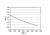
- the optical efficiency (that is, the reflection efficiency) when the incident angle ⁇ to the diffraction grating 131 is 80 ° is as shown in FIG.
- the optical efficiency when the incident angle ⁇ from the light source 112 to the diffraction grating 131 is 40 ° ( That is, the reflection efficiency is as shown in FIG. 2 and 3, it can be seen that light having different characteristics can be emitted from the diffraction grating 131 if the incident angles from the light sources 111 and 112 to the diffraction grating 131 are different. That is, if a plurality of light sources 111 and 112 are used, light having different characteristics can be emitted from the diffraction grating 131 even when the rotation of the rotary diffraction grating 130 is stopped.
- an LED or LD light source having a spectrum as shown in FIG. 4 is used as the light sources 111 and 112.
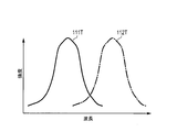
- a spectrum 111 ⁇ / b> S indicates a spectrum of the light source 111
- a spectrum 112 ⁇ / b> S indicates a spectrum of the light source 112.
- the LED or LD is used as the light source, as can be seen from FIG. 4, the light source light has a narrow half-value width and a steep spectrum.
- the light source 111 is turned on, the light source 112 is turned off, and the rotating diffraction grating 130 is rotated to obtain light as shown by the spectrum 111T in FIG.
- the light source 112 is turned on, the light source 111 is turned off, and the rotating diffraction grating 130 is rotated, thereby obtaining light as indicated by the spectrum 112T in FIG.
- continuous spectrum light consisting of the spectra 111T and 112T can be obtained.
- the continuous spectrum light is Can be used to measure.
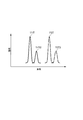
- the rotation diffraction grating 130 is rotated by a predetermined angle from the state 1 and the state 2 to stop the rotation, the light source 111 is turned on, and the light source 112 is turned off. Monochromatic light as shown by the spectrum 111T2 of 6 can be obtained. Further, by turning on the light source 112 and turning off the light source 111 at the rotation angle, it is possible to obtain monochromatic light as shown by the spectrum 112T2 in FIG.
- monochromatic light having different wavelengths can be obtained simply by switching the lighting of the light sources 111 and 112 by the lighting control unit 120 while the rotary diffraction grating 130 is stopped. Can do. As a result, light of different wavelengths can be created instantaneously.
- the light from the plurality of light sources 111 and 112, the slit 150, and the plurality of light sources 111 and 112 is incident and passes through the slit 150 provided on the emission side.
- a rotating diffraction grating 130 that can change the wavelength of light according to the rotation angle, a lighting control unit 120 that controls lighting of the plurality of light sources 111 and 112, and a rotation control unit 140 that controls the rotation of the rotating diffraction grating 130. Therefore, it is possible to realize a spectrometer 100 that can produce a wide variety of measurement light that meets various measurement requirements.
- By making it light it is possible to perform various measurements by adopting a configuration that also has a mode for obtaining light of two or more wavelengths according to the number of light sources that are turned on.
- the oxygen saturation is measured by alternately lighting the two light sources 111 and 112 while holding the diffraction grating 131 at a desired angle (wavelengths 650 nm and 810 nm), and after the measurement, the diffraction grating 131 is rotated and stopped again.
- the pulse is measured (550 nm), and then the diffraction grating 131 is rotated, and HbA1c can be measured by performing multivariate analysis using measurement light of a wide spectrum.
- fluorescence measurement can be performed by stopping the diffraction grating 131 at a desired angle and irradiating the phosphor with an excitation wavelength. Further, by rotating the angle, stopping and holding it again, it is possible to cope with various phosphor measurements (because the excitation wavelength can be varied). The same phosphor can be measured at various wavelengths. By rotating the diffraction grating 131, it is possible to cope with spectrum measurement of a solution.
- the spectrometer 100 can cope with various measurement methods and measurement objects by changing the programs of the lighting control unit 120 and the rotation control unit 140.
- a pulse oximeter will be described as an example. Since the conventional pulse oximeter is composed only of an LED that forms light for measuring oxygen saturation and a photodetector that receives the light, it is difficult to add a measurement object later.
- the spectrometer 100 of the present embodiment first sets a program so as to measure the oxygen saturation (for example, sets the measurement wavelength by setting the program of the rotation control unit 140), By changing the program, the measurement wavelength can be changed, and the measurement object can be added or changed later. Further, a more appropriate wavelength can be reselected even for the same measurement object.
- the spectroscope 100 according to the present embodiment can easily set the measurement wavelength according to the measurement target that the user wants to measure by simply changing the program of the lighting control unit 120 and the rotation control unit 140.
- FIG. 7, FIG. 8, and FIG. 9 show examples of the configuration of a measuring apparatus using the spectroscope 100 according to the above-described embodiment.
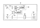
- FIG. 7 shows the measurement apparatus 10 that irradiates the measurement object with light separated by the spectroscope 100, that is, performs pre-spectroscopy.
- FIG. 8 shows a measuring apparatus 20 that splits the light that has passed through the measuring object with the spectroscope 100, that is, performs post-spectroscopy.
- FIG. 9 shows a measuring apparatus 30 that performs both pre-spectroscopy and post-spectroscopy.
- the measurement apparatus 10 that performs pre-spectroscopy in FIG. 7 makes the measurement light formed by the spectroscope 100 enter the measurement target arrangement unit 200.
- the measurement target arrangement unit 200 is formed of a container that holds a measurement target such as blood or urine.
- the light incident on the measurement target placement unit 200 is modulated by the measurement target in the measurement target placement unit 200 and then exits from the measurement target placement unit 200.
- This emitted light is received by the light receiving element 301 of the detector 300.
- the detector 300 analyzes how to receive the modulation of each wavelength component by a calculation unit (not shown), thereby analyzing the biological component to be measured.
- 7 is provided with a plurality of light sources 111 and 112 as described in FIG. Further, in FIG. 7, the slits 161 and 162 and the collimating lenses 171 and 172 in FIG. 1 are omitted as one slit 160 and one collimating lens 170 in order to simplify the drawing. The same applies to FIGS. 8 and 9.
- the 8 is configured to irradiate the measurement object arrangement unit 200 with light from the light source unit 110 provided with a plurality of light sources. Then, the light modulated by the measurement target in the measurement target arrangement unit 200 is split by the slit 160, the collimating lens 170, the rotating diffraction grating 130, the condensing lens 180, and the slit 150.
- the measurement device 30 that performs both the pre-spectral and post-spectroscopy in FIG. 9 irradiates the measurement target of the measurement target placement unit 200 with the light split by the spectroscope 100 and is modulated by the measurement target in the measurement target placement unit 200.
- the light is split by the slit 160-1, the collimating lens 170-1, the rotary diffraction grating 130-1, the condenser lens 180-1, and the slit 150-1.
- the condensing lens 180 is provided between the rotary diffraction grating 130 and the slit 150 .
- the reflection surface of the diffraction grating 131 is a concave surface, The optical lens 180 can be omitted.
- the case where the reflection type diffraction grating 131 is used has been described.
- the transmission type diffraction grating 131 may be used.
- the collimating and condensing optical elements may be either lenses or mirrors.
- the measurement target arrangement unit 200 includes a container holding a measurement target such as blood and urine
- the measurement target arrangement unit 200 includes a finger, a face, and the like as the measurement target.
- the living body itself may be arranged.
- the light receiving element 301 receives light transmitted or reflected by the measurement target.
- the spectroscope of the embodiment may be used as a light source. Thereby, a small light source having various wavelength peaks can be realized.
- the spectroscope of the present invention can be applied to, for example, a biological information measuring device that measures blood components and urine components.
- Spectrometer 110 Light source unit 111, 112 Light source 120 Lighting control unit 130, 130-1 Rotating diffraction grating 131 Diffraction grating 132 Actuator 140 Rotation control unit 150, 150-1, 160, 160-1, 161, 162 Slit 170, 170-1, 171, 172 Collimating lens 180, 180-1 Condensing lens 200 Measuring object arrangement part 300 Detector 301 Light receiving element
Landscapes
- Physics & Mathematics (AREA)
- Spectroscopy & Molecular Physics (AREA)
- General Physics & Mathematics (AREA)
- Analytical Chemistry (AREA)
- Health & Medical Sciences (AREA)
- Life Sciences & Earth Sciences (AREA)
- Chemical & Material Sciences (AREA)
- Biochemistry (AREA)
- General Health & Medical Sciences (AREA)
- Immunology (AREA)
- Pathology (AREA)
- Theoretical Computer Science (AREA)
- Mathematical Physics (AREA)
- Engineering & Computer Science (AREA)
- Investigating Or Analysing Materials By Optical Means (AREA)
- Spectrometry And Color Measurement (AREA)
Abstract
分光器100は、複数の光源111、112と、スリット150と、複数の光源111、112からの光を入射し、出射側に設けられたスリット150を通過する光の波長を回転角度に応じて変化させることができる回転回折格子130と、複数の光源111、112の点灯を制御する点灯制御部120と、回転回折格子130の回転を制御する回転制御部140と、を有する。
Description
本発明は、分光器および生体情報測定装置に関する。
従来、分光器として、例えば特許文献1に開示されたものがある。この種の分光器の基本原理は、光源光を回転回折格子を介してスリットに入射させることで、スリットから回転回折格子の回転角度に応じた波長の光を出射させることである。これにより、スリットからの出射光の波長は、回転回折格子の回転角度に応じたものとなり、分光が実現される。このスリットからの出射光は、例えば血液成分や尿中成分などの生体情報を測定するための測定光として用いられる。
このように回転回折格子を用いることにより、回転回折格子の回転角度に応じた連続したスペクトルの測定光を得ることができ、測定対象を所望の波長の測定光によって分析できるようになる。
ところで、上述したような分光器は、ヘマトクリット、血糖、酸素飽和度、血圧、脈拍、HbA1c、グルコアルブミン、血中アルコール、AGEs、血中コレステロール、血中中性脂肪、顔色、尿成分、血液などの体液、その他溶液(蛍光体など)、固体サンプルなど、多種多様なものが測定対象になる可能性がある。
そして、測定の方法によっては、連続スペクトルを用いる場合や、ある決まった複数の波長を用いる場合などがある。したがって、分光器は、測定方法に応じた多種多様な測定波を形成できることが好ましい。上述した回転回折格子を用いた分光器は、回転回折格子の回転角度を変化させることによって様々な波長の測定光を作り出すことができるので、この要求をある程度満たしている。しかしながら、回転回折格子を用いて異なる波長の測定光を作り出すためには、回転格子を回転させなければならないので、測定時間が回転速度に依存することになる。この結果、回転回折格子の回転性能が低いと、測定時間が長くなるなどの問題が生じる。
本発明は、以上の点を考慮してなされたものであり、様々な測定の要求にかなった、多種多様な測定光を作り出すことができる分光器を提供する。
本発明の分光器の一つの態様は、
複数の光源と、
スリットと、
前記複数の光源からの光を入射し、出射側に設けられた前記スリットを通過する光の波長を回転角度に応じて変化させることができる回転回折格子と、
前記複数の光源の点灯を制御する点灯制御部と、
前記回転回折格子の回転を制御する回転制御部と、
を具備する。
複数の光源と、
スリットと、
前記複数の光源からの光を入射し、出射側に設けられた前記スリットを通過する光の波長を回転角度に応じて変化させることができる回転回折格子と、
前記複数の光源の点灯を制御する点灯制御部と、
前記回転回折格子の回転を制御する回転制御部と、
を具備する。
本発明によれば、回転回折格子に加えて、複数の光源を設け、回転回折格子の回転を制御するとともに複数の光源の点灯を制御するようにしたことにより、様々な測定の要求にかなった、多種多様な測定光を作り出すことができるようになる。
以下、本発明の実施の形態について、図面を参照して詳細に説明する。
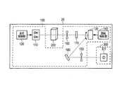
図1は本発明の実施の形態に係る分光器100の全体構成を示す略線図である。本実施の形態の分光器100は、複数の光源111、112と、スリット150と、光源111、112の点灯を制御する点灯制御部120と、複数の光源111、112からの光を入射し、出射側に設けられたスリット150を通過する光の波長を回転角度に応じて変化させることができる回転回折格子130と、回転回折格子130の回転を制御する回転制御部140と、を有する。
本実施の形態では、説明を簡単化するために2つの光源111、112を設けた場合について述べるが、3つ以上の光源を設けてもよい。本実施の形態の場合、光源111、112として、LED(Light Emitting Diode)またはLD(Laser Diode)が用いられている。これにより、光源を小型化、小電力化でき、発熱量も小さくできる。
光源111の光は、スリット161およびコリメートレンズ171を介して回転回折格子130に入射する。光源112の光は、スリット162およびコリメートレンズ172を介して回転回折格子130に入射する。
回転回折格子130は、回折格子131と、この回折格子131を回転駆動するアクチュエーター132と、から構成されている。回転回折格子130は、アクチュエーター132によって回折格子131を図の矢印Rの方向に回転させる。アクチュエーター132の回転駆動方式としては、電磁駆動方式や、MEMS(Micro Electro Mechanical Systems)方式、圧電方式、静電方式などの種々の方式を用いることができる。
回転回折格子130から出射した光は、集光レンズ180を介してスリット150に到達しスリット150を通過する。回転回折格子130およびスリット150を用いた分光は既知の技術なので、ここでは詳述しないが、要は、回転回折格子130の回転角度によってスリット150を通過する光の波長を変えることで分光を実現している。スリット150を通過した光は、例えば血液成分や尿中成分などの生体情報を測定するための測定光として用いられる。
ここで、光源が1つであれば、スリット150を通過する光の波長は回転回折格子130の回転角度によって一意に定まる。しかし、本実施の形態の場合には、複数の光源111、112を用いているので、回転回折格子130の回転角度が同じであっても、各光源111、112からの光の回転回折格子130への入射角が異なるように各光源111、112を配置したり、各光源111、112として光学特性が異なるものを用いることで、スリット150を通過する光の波長を変えることができる。加えて、点灯制御部120による光源111、112の点灯タイミング制御と、回転制御部140による回転回折格子130の回転制御とを、組み合わせることで、多種多様な測定光を作り出すことができる。
各光源111、112としては、異なるスペクトルを持つ光源を用いてもよいし、同一のスペクトルを持つ光源を用いてもよい。本実施の形態の場合には、異なるスペクトルを持つ2つの光源111、112を用い、各光源111、112からの光が回転回折格子130に異なる入射角α、βで入射するように各光源111、112が配置されている。
ところで、回折格子への入射角の違いによって、回折格子からの反射効率は異なる。これについて説明する。ここでは、説明を簡単にするために、光源111、112が同一のスペクトルを持つ光源であるとする。回折格子131のピッチ幅が1.5μm、ピッチ深さが0.2μmであり、かつ光源111、112として、平坦なスペクトルを持つ同一の2つの光源111、112を用いた場合において、光源111から回折格子131への入射角αが80°のときの光学効率(つまり反射効率)は図2に示すようになり、光源112から回折格子131への入射角βが40°のときの光学効率(つまり反射効率)は図3に示すようになる。図2および図3から、各光源111、112から回折格子131への入射角が異なれば、回折格子131から異なる特性の光を出射させることができることが分かる。つまり、複数の光源111、112を用いれば、回転回折格子130の回転が停止していても、回折格子131から異なる特性の光を出射させることができるようになる。
加えて、異なるスペクトルを持つ複数の光源を用いたことにより、従来の分光器よりも広い波長範囲の測定光を得ることができる。その際、最適な入射角に設定することで、特定波長の光学効率を高めることが可能である。
次に、本実施の形態の動作例について説明する。
この動作例では、光源111、112として、図4に示すようなスペクトルを持つLEDまたはLD光源を用いる。図4において、スペクトル111Sは光源111のスペクトルを示し、スペクトル112Sは光源112のスペクトルを示す。LEDまたはLDを光源とする場合には、図4からも分かるように、光源光は、半値幅が狭く、急峻なスペクトルとなる。
<動作例1>
この動作例1では、回転回折格子130を回転させて測定する。
この動作例1では、回転回折格子130を回転させて測定する。
先ず手順1として、光源111を点灯させ、光源112を消灯して、回転回折格子130を回転させることにより、スリット150の出射側に図5のスペクトル111Tで示したような光を得る。
次に手順2として、光源112を点灯させ、光源111を消灯して、回転回折格子130を回転させることにより、スリット150の出射側に図5のスペクトル112Tで示したような光を得る。
このような動作により、スペクトル111T、112Tからなる連続的なスペクトルの光を得ることができ、分光器100によって得られた光を用いて測定を行う測定装置では、この連続的なスペクトルの光を用いて測定を行うことができるようになる。
<動作例2>
この動作例2では、回転回折格子130の回転を停止させて測定する。
この動作例2では、回転回折格子130の回転を停止させて測定する。
状態1として、光源111を点灯させ、光源112を消灯することにより、スリット150の出射側に図6のスペクトル111Tで示したような単色光を得ることができる。
状態2として、光源112を点灯させ、光源111を消灯することにより、スリット150の出射側に図6のスペクトル112Tで示したような単色光を得ることができる。
さらに、状態3として、状態1および状態2の状態から回転回折格子130を所定角度回転させて回転を停止し、光源111を点灯させ、光源112を消灯することにより、スリット150の出射側に図6のスペクトル111T2で示したような単色光を得ることができる。また、その回転角度で、光源112を点灯させ、光源111を消灯することにより、スリット150の出射側に図6のスペクトル112T2で示したような単色光を得ることができる。
このように、ある角度で回転回折格子130の回転を停止し、光源111、112を交互に点灯する処理を行うことにより、異なる波長の単色光を得ることができる。ここで、1つの光源を用い、この光源の光を回転回折格子を介してスリットに入射させる従来の分光器においては、異なる波長の単色光を得るためには回転回折格子を機械的に回転させなければならない。よって、その回転にある程度の時間を要する。これに対して、本実施の形態の分光器100においては、回転回折格子130を停止させたまま、点灯制御部120によって光源111、112の点灯を切り替えるだけで、異なる波長の単色光を得ることができる。この結果、瞬時に異なる波長の光を作り出すことができる。
さらに、状態1~3を組合せることで、無数の波長の光を作り出すことができ、任意の波長での測定が可能となる。
以上説明したように、本実施の形態によれば、複数の光源111、112と、スリット150と、複数の光源111、112からの光を入射し、出射側に設けられたスリット150を通過する光の波長を回転角度に応じて変化させることができる回転回折格子130と、複数の光源111、112の点灯を制御する点灯制御部120と、回転回折格子130の回転を制御する回転制御部140と、を有する構成としたことにより、様々な測定の要求にかなった、多種多様な測定光を作り出すことができる分光器100を実現できる。例えば、回転回折格子130を連続的に回転させることによって連続スペクトルを得るモードと、回転回折格子130を所定の回転角度で停止させ、複数の光源111、112のうち2つ以上の光源を交互に点灯させることによって、点灯させた光源の数に応じた2つ以上の波長の光を得るモードと、を兼ね備える構成とすることで、様々な測定が可能となる。
例えば、回折格子131を所望の角度で保持したまま2光源111、112を交互に点灯させることで酸素飽和度を測定し(波長650nm、810nm)、測定後に回折格子131を回転させ、再度停止し保持することで脈拍を測定し(550nm)、その後回折格子131を回転させ広域のスペクトルの測定光によって多変量解析することでHbA1cを測定するなどが可能になる。
また例えば、回折格子131を所望の角度で停止し、励起波長を蛍光体に照射することで蛍光測定が可能となる。また、角度を回転させ、再度停止し保持することで、様々な蛍光体の測定に対応できる(励起波長を可変できるため)。また、同じ蛍光体でも様々な波長で測定できる。回折格子131を回転させることで溶液のスペクトル測定にも対応できる。
本実施の形態の分光器100は、点灯制御部120および回転制御部140のプログラムを変更することで、様々な測定方法、測定対象に対応できる。例えばパルスオキシメータを例に説明する。従来のパルスオキシメータは、酸素飽和度を測定するための光を形成するLEDとその光を受光するフォトディテクターのみで構成されているため、後から測定対象を追加することが困難である。それに対し、本実施の形態の分光器100は、初め酸素飽和度を測定するようにプログラムを設定(例えば回転制御部140のプログラムを設定することにより測定波長を設定)しておいても、そのプログラムを追加変更することで、測定波長を変えることができ、これにより後から測定対象を追加変更することができる。また、同一測定対象でも、より適切な波長を再選択することもできる。本実施の形態の分光器100は、点灯制御部120および回転制御部140のプログラムを変更するだけで、ユーザーが測定したい測定対象に合わせて容易に測定波長を設定できる。
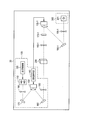
図7、図8および図9に、上述した実施の形態の分光器100を用いた測定装置の構成例を示す。図7は、分光器100によって分光した光を測定対象に照射する、つまり前分光を行う測定装置10を示す。図8は、測定対象を通過した光を分光器100によって分光する、つまり後分光を行う測定装置20を示す。図9は、前分光および後分光の両方を行う測定装置30を示す。
図7の前分光を行う測定装置10は、分光器100によって形成した測定光を測定対象配置部200に入射する。測定対象配置部200は、例えば血液や尿などの測定対象を保持した容器からなる。測定対象配置部200に入射した光は、測定対象配置部200内の測定対象によって変調された後に測定対象配置部200から出射する。この出射光は、検出器300の受光素子301によって受光される。検出器300は、受光素子301の受光結果に基づいて、各波長成分の変調の受け方を演算部(図示せず)で分析することで、測定対象の生体成分などを分析する。なお、図7の光源ユニット110には図1で説明したように複数の光源111、112が設けられている。また、図7では、図を簡単化するために、図1のスリット161、162およびコリメートレンズ171、172を、それぞれ1つのスリット160および1つのコリメートレンズ170として省略して示してある。これは、図8および図9でも同様である。
図8の後分光を行う測定装置20は、複数の光源が設けられた光源ユニット110からの光を測定対象配置部200に照射するようになっている。そして、測定対象配置部200内の測定対象によって変調された光を、スリット160、コリメートレンズ170、回転回折格子130、集光レンズ180およびスリット150によって分光するようになっている。
図9の前分光および後分光の両方を行う測定装置30は、分光器100によって分光した光を測定対象配置部200の測定対象に照射するとともに、測定対象配置部200内の測定対象によって変調された光を、スリット160-1、コリメートレンズ170-1、回転回折格子130-1、集光レンズ180-1およびスリット150-1によって分光するようになっている。このように前分光および後分光の両方を行うことにより、分光の分解能を上げることができる。
なお上述の実施の形態では、回転回折格子130とスリット150との間に集光レンズ180を設けた場合について述べたが、例えば回折格子131の反射面を凹面形状のものとすることで、集光レンズ180を省略することもできる。
また、上述の実施の形態では、反射型の回折格子131を用いた場合について述べたが、透過型の回折格子131を用いてもよい。また、コリメート、集光光学素子はレンズ、ミラーどちらでもよい。
また、上述の実施の形態では、測定対象配置部200が例えば血液や尿などの測定対象を保持した容器からなる場合について述べたが、測定対象配置部200には測定対象として指や顔などの生体自体を配置してもよい。この場合、受光素子301では測定対象によって透過または反射された光が受光されることになる。さらに、実施の形態の分光器を測定装置として用いる場合について述べたが、実施の形態の分光器を光源として用いてもよい。これにより、様々な波長ピークを持つ、小型の光源を実現できる。
上述の実施の形態は、本発明を実施するにあたっての具体化の一例を示したものに過ぎず、これらによって本発明の技術的範囲が限定的に解釈されてはならないものである。すなわち、本発明はその要旨、またはその主要な特徴から逸脱することの無い範囲で、様々な形で実施することができる。
2015年4月17日出願の特願2015-085058の日本出願に含まれる明細書、図面および要約書の開示内容は、すべて本願に援用される。
本発明の分光器は、例えば血液成分や尿中成分を測定する生体情報測定装置に適用できる。
10、20、30 測定装置
100 分光器
110 光源ユニット
111、112 光源
120 点灯制御部
130、130-1 回転回折格子
131 回折格子
132 アクチュエーター
140 回転制御部
150、150-1、160、160-1、161、162 スリット
170、170-1、171、172 コリメートレンズ
180、180-1 集光レンズ
200 測定対象配置部
300 検出器
301 受光素子
100 分光器
110 光源ユニット
111、112 光源
120 点灯制御部
130、130-1 回転回折格子
131 回折格子
132 アクチュエーター
140 回転制御部
150、150-1、160、160-1、161、162 スリット
170、170-1、171、172 コリメートレンズ
180、180-1 集光レンズ
200 測定対象配置部
300 検出器
301 受光素子
Claims (4)
- 複数の光源と、
スリットと、
前記複数の光源からの光を入射し、出射側に設けられた前記スリットを通過する光の波長を回転角度に応じて変化させることができる回転回折格子と、
前記複数の光源の点灯を制御する点灯制御部と、
前記回転回折格子の回転を制御する回転制御部と、
を具備する分光器。 - 前記回転回折格子を連続的に回転させることによって連続スペクトルを得るモードと、
前記回転回折格子を所定の回転角度で停止させ、前記複数の光源のうち2つ以上の光源を交互に点灯させることによって、前記点灯させた光源の数に応じた2つ以上の波長の光を得るモードと、
を有する請求項1に記載の分光器。 - 前記複数の光源は、前記回転回折格子への入射角が互いに異なるような位置に配置されている、
請求項1または請求項2に記載の分光器。 - 請求項1に記載の分光器と、
測定対象の生体を保持し、前記分光器によって分光された光、或いは、前記分光器による分光前の前記複数の光源からの光を透過して出射する位置に配置された測定対象配置部と、
前記測定対象配置部を透過または反射し、かつ分光された光を受光する受光素子と、
を具備する生体情報測定装置。
Applications Claiming Priority (2)
| Application Number | Priority Date | Filing Date | Title |
|---|---|---|---|
| JP2015085058A JP2016205889A (ja) | 2015-04-17 | 2015-04-17 | 分光器および生体情報測定装置 |
| JP2015-085058 | 2015-04-17 |
Publications (1)
| Publication Number | Publication Date |
|---|---|
| WO2016166981A1 true WO2016166981A1 (ja) | 2016-10-20 |
Family
ID=57125917
Family Applications (1)
| Application Number | Title | Priority Date | Filing Date |
|---|---|---|---|
| PCT/JP2016/002017 Ceased WO2016166981A1 (ja) | 2015-04-17 | 2016-04-14 | 分光器および生体情報測定装置 |
Country Status (3)
| Country | Link |
|---|---|
| JP (1) | JP2016205889A (ja) |
| TW (1) | TW201638566A (ja) |
| WO (1) | WO2016166981A1 (ja) |
Cited By (1)
| Publication number | Priority date | Publication date | Assignee | Title |
|---|---|---|---|---|
| JP2020085842A (ja) * | 2018-11-30 | 2020-06-04 | セイコーエプソン株式会社 | 分光カメラおよび電子機器 |
Families Citing this family (1)
| Publication number | Priority date | Publication date | Assignee | Title |
|---|---|---|---|---|
| US12326363B2 (en) | 2020-07-30 | 2025-06-10 | Answeray Inc. | Spectroscope |
Citations (6)
| Publication number | Priority date | Publication date | Assignee | Title |
|---|---|---|---|---|
| JPS6347622A (ja) * | 1986-08-14 | 1988-02-29 | Shimadzu Corp | 分光装置 |
| JPS6358127A (ja) * | 1986-08-28 | 1988-03-12 | Shimadzu Corp | デンシトメ−タ |
| JPH08201172A (ja) * | 1994-10-13 | 1996-08-09 | Perstorp Analytical Inc | 発光ダイオードを光源とする分光光度計 |
| JP2004286645A (ja) * | 2003-03-24 | 2004-10-14 | Minolta Co Ltd | 多波長光源装置 |
| US20050154268A1 (en) * | 2004-01-12 | 2005-07-14 | In-Duk Hwang | Body component concentration measuring apparatus and method |
| JP2009210584A (ja) * | 2008-03-03 | 2009-09-17 | Agilent Technol Inc | 工程内で小粒子の粒径分布を計算する方法及びシステム |
-
2015
- 2015-04-17 JP JP2015085058A patent/JP2016205889A/ja active Pending
-
2016
- 2016-04-14 WO PCT/JP2016/002017 patent/WO2016166981A1/ja not_active Ceased
- 2016-04-15 TW TW105111735A patent/TW201638566A/zh unknown
Patent Citations (6)
| Publication number | Priority date | Publication date | Assignee | Title |
|---|---|---|---|---|
| JPS6347622A (ja) * | 1986-08-14 | 1988-02-29 | Shimadzu Corp | 分光装置 |
| JPS6358127A (ja) * | 1986-08-28 | 1988-03-12 | Shimadzu Corp | デンシトメ−タ |
| JPH08201172A (ja) * | 1994-10-13 | 1996-08-09 | Perstorp Analytical Inc | 発光ダイオードを光源とする分光光度計 |
| JP2004286645A (ja) * | 2003-03-24 | 2004-10-14 | Minolta Co Ltd | 多波長光源装置 |
| US20050154268A1 (en) * | 2004-01-12 | 2005-07-14 | In-Duk Hwang | Body component concentration measuring apparatus and method |
| JP2009210584A (ja) * | 2008-03-03 | 2009-09-17 | Agilent Technol Inc | 工程内で小粒子の粒径分布を計算する方法及びシステム |
Cited By (2)
| Publication number | Priority date | Publication date | Assignee | Title |
|---|---|---|---|---|
| JP2020085842A (ja) * | 2018-11-30 | 2020-06-04 | セイコーエプソン株式会社 | 分光カメラおよび電子機器 |
| JP7192447B2 (ja) | 2018-11-30 | 2022-12-20 | セイコーエプソン株式会社 | 分光カメラおよび電子機器 |
Also Published As
| Publication number | Publication date |
|---|---|
| JP2016205889A (ja) | 2016-12-08 |
| TW201638566A (zh) | 2016-11-01 |
Similar Documents
| Publication | Publication Date | Title |
|---|---|---|
| US7265830B2 (en) | Fourier Transform spectrometer apparatus using multi-element MEMS | |
| TWI741104B (zh) | 緊密的光束整形及操縱總成 | |
| JP4414771B2 (ja) | 共焦点顕微分光装置 | |
| KR102444284B1 (ko) | 라만 신호 측정 방법, 장치 및 라만 신호 측정 장치를 포함하는 생체 정보 분석 장치 | |
| US12611114B2 (en) | Broadband multispectral diagnostic systems and methods | |
| CN105008982A (zh) | 光谱控制系统 | |
| CN104737000A (zh) | 用于分析系统的装置、具有该装置的分析系统和用于使用该装置的方法 | |
| JP2006138734A (ja) | 光スペクトラムアナライザ | |
| JP6387610B2 (ja) | 生体情報測定装置 | |
| JPWO2017169788A1 (ja) | パルス光生成装置、光照射装置、光加工装置、光応答測定装置、顕微鏡装置、及びパルス光生成方法 | |
| CN105352923B (zh) | 一种快速宽视场体全息荧光显微成像系统 | |
| WO2016166981A1 (ja) | 分光器および生体情報測定装置 | |
| CN115016113B (zh) | 用于光脉冲调制的斩波器及基于调制脉冲的成像装置 | |
| WO2016061710A1 (zh) | 一种快速宽视场体全息荧光显微成像系统 | |
| CN107076540B (zh) | 多功能分光装置 | |
| US20140118743A1 (en) | Optical measuring apparatus and optical measuring method | |
| WO2012131812A1 (ja) | 分光器 | |
| CN103278449A (zh) | 多通道光学检测装置 | |
| JP2010164511A (ja) | センサーユニット、テラヘルツ分光測定装置およびテラヘルツ分光測定方法 | |
| JP2016138828A (ja) | 生体成分情報測定装置 | |
| RU2601386C2 (ru) | Спектрометр, содержащий пространственный модулятор света | |
| JP2016125826A (ja) | 分析装置 | |
| JP5936387B2 (ja) | 表面プラズモンデバイス | |
| JP5856819B2 (ja) | 光源装置および光計測装置 | |
| US9995626B1 (en) | Micro-fluorescence capable micro-Raman spectrometer |
Legal Events
| Date | Code | Title | Description |
|---|---|---|---|
| 121 | Ep: the epo has been informed by wipo that ep was designated in this application |
Ref document number: 16779775 Country of ref document: EP Kind code of ref document: A1 |
|
| NENP | Non-entry into the national phase |
Ref country code: DE |
|
| 122 | Ep: pct application non-entry in european phase |
Ref document number: 16779775 Country of ref document: EP Kind code of ref document: A1 |