WO2016166897A1 - 電子機器の装着バンド及び電子機器 - Google Patents
電子機器の装着バンド及び電子機器 Download PDFInfo
- Publication number
- WO2016166897A1 WO2016166897A1 PCT/JP2015/061901 JP2015061901W WO2016166897A1 WO 2016166897 A1 WO2016166897 A1 WO 2016166897A1 JP 2015061901 W JP2015061901 W JP 2015061901W WO 2016166897 A1 WO2016166897 A1 WO 2016166897A1
- Authority
- WO
- WIPO (PCT)
- Prior art keywords
- band
- zigzag
- spring
- electronic device
- mounting
- Prior art date
- Legal status (The legal status is an assumption and is not a legal conclusion. Google has not performed a legal analysis and makes no representation as to the accuracy of the status listed.)
- Ceased
Links
Images










Classifications
-
- A—HUMAN NECESSITIES
- A44—HABERDASHERY; JEWELLERY
- A44C—PERSONAL ADORNMENTS, e.g. JEWELLERY; COINS
- A44C5/00—Bracelets; Wrist-watch straps; Fastenings for bracelets or wrist-watch straps
- A44C5/02—Link constructions
- A44C5/025—Link constructions with links threaded on a band
- A44C5/027—Link constructions with links threaded on a band the band also made of links
-
- B—PERFORMING OPERATIONS; TRANSPORTING
- B33—ADDITIVE MANUFACTURING TECHNOLOGY
- B33Y—ADDITIVE MANUFACTURING, i.e. MANUFACTURING OF THREE-DIMENSIONAL [3D] OBJECTS BY ADDITIVE DEPOSITION, ADDITIVE AGGLOMERATION OR ADDITIVE LAYERING, e.g. BY 3D PRINTING, STEREOLITHOGRAPHY OR SELECTIVE LASER SINTERING
- B33Y80/00—Products made by additive manufacturing
-
- A—HUMAN NECESSITIES
- A44—HABERDASHERY; JEWELLERY
- A44C—PERSONAL ADORNMENTS, e.g. JEWELLERY; COINS
- A44C5/00—Bracelets; Wrist-watch straps; Fastenings for bracelets or wrist-watch straps
- A44C5/0007—Bracelets specially adapted for other functions or with means for attaching other articles
- A44C5/0023—Bracelets specially adapted for other functions or with means for attaching other articles for therapeutic purposes
-
- A—HUMAN NECESSITIES
- A44—HABERDASHERY; JEWELLERY
- A44C—PERSONAL ADORNMENTS, e.g. JEWELLERY; COINS
- A44C5/00—Bracelets; Wrist-watch straps; Fastenings for bracelets or wrist-watch straps
- A44C5/0007—Bracelets specially adapted for other functions or with means for attaching other articles
- A44C5/003—Bracelets specially adapted for other functions or with means for attaching other articles with a storage compartment
-
- A—HUMAN NECESSITIES
- A44—HABERDASHERY; JEWELLERY
- A44C—PERSONAL ADORNMENTS, e.g. JEWELLERY; COINS
- A44C5/00—Bracelets; Wrist-watch straps; Fastenings for bracelets or wrist-watch straps
- A44C5/0053—Flexible straps
- A44C5/0069—Flexible straps extensible
-
- A—HUMAN NECESSITIES
- A41—WEARING APPAREL
- A41F—GARMENT FASTENINGS; SUSPENDERS
- A41F9/00—Belts, girdles, or waistbands for trousers or skirts
- A41F9/002—Free belts
-
- A—HUMAN NECESSITIES
- A44—HABERDASHERY; JEWELLERY
- A44C—PERSONAL ADORNMENTS, e.g. JEWELLERY; COINS
- A44C15/00—Other forms of jewellery
- A44C15/0045—Jewellery specially adapted to be worn on a specific part of the body not fully provided for in groups A44C1/00 - A44C9/00
- A44C15/006—Jewellery specially adapted to be worn on a specific part of the body not fully provided for in groups A44C1/00 - A44C9/00 on the head, e.g. diadem
Definitions
- the technology disclosed in this application relates to a wearable electronic device mounting band and an electronic device.
- JP2015-57100A JP 2002-61691 A Japanese Utility Model Publication 2000-25 Special table 2011-510793 gazette
- the technology disclosed in the present application aims to provide a mounting band for an electronic device that can improve comfort when worn on the body.
- a mounting band for an electronic device including a plurality of first zigzag springs and a plurality of second zigzag springs.
- the plurality of first zigzag springs are arranged in the length direction and the width direction of the band body in the longitudinal direction of the band body formed in a band shape or an annular shape, and are expanded and contracted in the length direction of the band body. Forming part.
- the plurality of second zigzag springs are arranged in the longitudinal direction and the width direction of the band main body with the width direction of the band main body as an axial direction, and form a stretchable portion in the width direction of the band main body.
- One zigzag spring and spring constant are different.
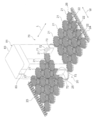
- FIG. 2 is an enlarged view of a structure in which one first spring row and another first spring row shown in FIG. 1 are connected by a second zigzag spring.
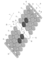
- FIG. 2 is an enlarged view of a structure in which one second spring row and another second spring row shown in FIG.
- FIG. 1 It is a figure which shows the state which removed the electronic device main body from the mounting part in the electronic device which concerns on 2nd embodiment. It is a figure which shows the state which attached the electronic device main body to the mounting part in the electronic device shown by FIG. It is a perspective view of the electronic device which concerns on 3rd embodiment. It is a figure which shows the modification of the electronic device which concerns on 3rd embodiment. It is a perspective view of the wearing band concerning a 4th embodiment. It is a B section enlarged view of the wearing band shown in FIG.
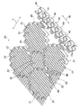
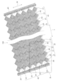
- the electronic device 10 according to the first embodiment shown in FIG. 1 is a wearable electronic device, and includes a mounting band 20 and an electronic device main body 11.
- the wearing band 20 is, for example, worn on a predetermined part of the body such as an arm, a waist, and a head, and is formed in a belt shape in which the L direction is the length direction and the W direction is the width direction.
- the mounting band 20 includes a plurality of first zigzag springs 21, a plurality of second zigzag springs 22, a connection portion 23, a connected portion 24, and a mounting portion 25.
- the plurality of first zigzag springs 21, the plurality of second zigzag springs 22, the connection part 23, the connected part 24, and the mounting part 25 form a band body 26 of the mounting band 20.
- the mounting band 20 is formed by a plurality of first zigzag springs 21, a plurality of second zigzag springs 22, a connection part 23, a connected part 24, and a mounting part 25.
- wearing band 20 and the band main body 26 are synonymous.
- the plurality of first zigzag springs 21 and the plurality of second zigzag springs 22 are arranged in the L direction and the W direction.
- the W direction intersects (as an example, orthogonal) with the L direction.
- each of the plurality of first zigzag springs 21 is formed with the L direction as an axial direction.
- Each of the plurality of first zigzag springs 21 has a plurality of S-shaped portions continuous in the L direction.
- the plurality of first zigzag springs 21 form a stretchable portion in the length direction of the mounting band 20 (band main body 26).
- each of the plurality of second zigzag springs 22 is formed with the W direction as an axial direction.
- Each of the plurality of second zigzag springs 22 has a plurality of S-shaped portions continuous in the W direction.
- the plurality of second zigzag springs 22 form stretchable portions in the width direction of the mounting band 20 (band main body 26).
- a plurality of S-shaped portions that are continuous in the L direction can be regarded as a plurality of crank-shaped portions that are continuous in the L direction.
- a plurality of S-shaped portions that are continuous in the W direction can be regarded as a plurality of crank-shaped portions that are continuous in the W direction.
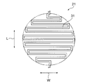
- the outer shape of the first zigzag spring 21 is a substantially regular octagon in plan view. That is, the first zigzag spring 21 has a plurality of strand portions 31 extending in the W direction and arranged in the L direction. When the end portions in the length direction of the plurality of strand portions 31 are connected, a substantially regular octagon is formed. Is formed.
- the strand portion 31 is formed in a plate shape with the L direction as the plate thickness direction.
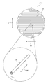
- the outer shape of the second zigzag spring 22 is a substantially regular octagon in plan view. That is, the second zigzag spring 22 has a plurality of strand portions 32 extending in the L direction and arranged in the W direction. When the end portions in the length direction of the plurality of strand portions 32 are connected, a substantially regular octagon is formed. Is formed.
- the strand portion 32 is formed in a plate shape with the W direction as the plate thickness direction.
- the strand portion 31 of the first zigzag spring 21 and the strand portion 32 of the second zigzag spring 22 are formed with the same plate thickness.
- the first zigzag spring 21 is larger in size (width and length) than the second zigzag spring 22. Further, the first zigzag spring 21 has a smaller spring constant than the second zigzag spring 22 because it is larger than the second zigzag spring 22 (is easily deformed). As described above, the mounting band 20 shown in FIG. 1 is easier to extend in the L direction than in the W direction because the first zigzag spring 21 has a larger size (a smaller spring constant) than the second zigzag spring 22. Has anisotropy.
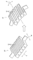
- the first zigzag spring 21 since the wire portions 31 of the first zigzag spring 21 extend in the W direction and are arranged in the L direction, the first zigzag spring 21 extends well in the L direction due to the tensile and bending load F. It bends well around an axis parallel to the W direction.
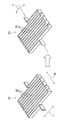
- the strands 32 of the second zigzag spring 22 extend in the L direction and line up in the W direction. It is difficult to extend in the direction, and it is difficult to bend around an axis parallel to the W direction.
- the first zigzag spring 21 is larger in size than the second zigzag spring 22, so the mounting band 20 also has a characteristic that it is easy to bend around an axis parallel to the W direction.
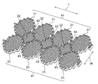
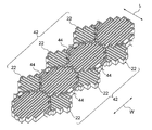
- the plurality of first zigzag springs 21 and the plurality of second zigzag springs 22 for exhibiting such characteristics are arranged as follows. That is, as shown in FIG. 7, the plurality of first zigzag springs 21 form a plurality of first spring rows 41 having a plurality of first zigzag springs 21 that are continuous in the L direction. The plurality of first spring rows 41 are arranged in the W direction. A connecting portion 43 is formed between adjacent first zigzag springs 21 in each first spring row 41.
- the plurality of second zigzag springs 22 form a plurality of second spring rows 42 having a plurality of second zigzag springs 22 connected in the W direction.
- the plurality of second spring rows 42 are arranged in the L direction.
- a connecting portion 44 is formed between adjacent second zigzag springs 22 in each second spring row 42.
- each of the plurality of second zigzag springs 22 includes a connecting portion 43 in one first spring row 41 and a first spring row 41 among the plurality of first spring rows 41.
- column 41 next to is connected.
- the connecting portion 43 and the connecting portion 44 are connected in a cross shape.
- the plurality of first zigzag springs 21 and the plurality of second zigzag springs 22 are formed on the same plane extending in the L direction and the W direction by being arranged as described above.
- the mounting band 20 is formed in a plate shape by forming a plurality of first zigzag springs 21 and a plurality of second zigzag springs 22 on the same surface extending in the L direction and the W direction.
- connection portion 23 is formed at one end portion in the length direction of the mounting band 20 and has a plurality of convex portions 53 arranged in the W direction.
- the connected portion 24 is formed at the other end portion in the length direction of the mounting band 20 and has a plurality of concave portions 54 arranged in the W direction.
- the connecting portion 23 is connected to the connected portion 24.
- the mounting band 20 is formed in an annular shape (cylindrical shape) with the L direction as the circumferential direction. The wearing band 20 can be returned to a band shape by releasing the connection between the connecting portion 23 and the connected portion 24.
- the mounting portion 25 is formed at the center in the length direction of the mounting band 20 as an example.
- the mounting portion 25 is formed in a long shape in which the L direction is the short direction and the W direction is the long direction.
- the mounting portion 25 is formed in a plate shape and is hard.
- a plurality of first zigzag springs 21 and a plurality of second zigzag springs 22 are arranged on both sides in the L direction with respect to the mounting portion 25.
- the plurality of first zigzag springs 21, the plurality of second zigzag springs 22, the connection part 23, the connected part 24, and the mounting part 25 are formed integrally with the mounting band 20.
- the mounting band 20 is made of resin, for example.
- the mounting band 20 can be manufactured by a processing method such as a three-dimensional printer, resin molding, and punching.
- the electronic device main body 11 is mounted on the mounting unit 25.
- the electronic device main body 11 is an electronic unit including, for example, a sensor, an arithmetic element, a storage element, a battery, a display, an operation switch, a housing, and the like.
- a semiconductor chip may be used as the electronic device body 11.
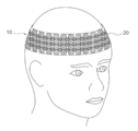
- the electronic device 10 having the above configuration is used as follows, for example. That is, in FIG. 9, the electronic device 10 is a wristband type wearable device, and the wearing band 20 is worn on the user's wrist. In FIG. 10, the electronic device 10 is a waist belt type wearable device, and the wearing band 20 is worn on the user's waist. Furthermore, in FIG. 11, the electronic device 10 is a headband type wearable device, and the wearing band 20 is worn on the user's head.
- the electronic device 10 is not limited to the usage examples shown in FIGS. 9 to 11, but may be of a type that can be worn on other parts of the body, such as a ring type or a bracelet type.
- the length and width of the wearing band 20 are appropriately set according to the body part that is the wearing destination.
- the mounting band 20 includes a plurality of first zigzag springs 21 and a plurality of second zigzag springs 22, so that the weight is reduced.
- the first zigzag spring 21 whose axial direction is the length direction of the mounting band 20 is larger than the second zigzag spring 22 whose axial direction is the width direction of the mounting band 20 (the spring constant is small).
- the wearing band 20 when the wearing band 20 is worn on the body, the wearing band 20 extends well in the length direction (circumferential direction), and the wearing band 20 bends well around an axis parallel to the width direction.
- the wearing band 20 since the wearing band 20 extends in the width direction by the second zigzag spring 22, it is possible to deal with complicated unevenness of the body.
- the wearing band 20 since the wearing band 20 is well adapted to the complex shape of the body and is flexible and worn on the body, it does not bother, so the comfort when the wearing band 20 is worn on the body can be improved.
- the mounting band 20 is formed in a band shape, and a connecting portion 23 is formed at one end of the mounting band 20 in the length direction, and a connecting portion 23 is connected to the other end of the mounting band 20 in the length direction.
- a connected portion 24 connected to the portion 23 is formed. Therefore, when the connecting portion 23 is connected to the connected portion 24, the mounting band 20 can be formed into an annular shape (tubular shape).
- the wearing band 20 is easy to extend in the length direction (circumferential direction), the wearing band 20 can be worn on the body (for example, a wrist) with the wearing band 20 in an annular shape. Thereby, there is no need to fasten or remove the belt like a wristwatch band, so that the convenience of the wearing band 20 can be improved.
- the wearing band 20 is formed in a band shape (planar shape). Therefore, since the mounting band 20 can be manufactured in a belt-like state, the mounting band 20 can be easily manufactured, and if the mounting band 20 is banded when not in use, the mounting band 20 can be easily stored. There are advantages.
- the plurality of first zigzag springs 21 and the plurality of second zigzag springs 22 are formed on the same surface extending in the length direction and the width direction of the mounting band 20, whereby the mounting band 20 has a plate shape. ing. Therefore, since the mounting band 20 is made thin, the bulk of the mounting band 20 can be suppressed, so that the comfort when the mounting band 20 is mounted on the body can be further improved.
- the plurality of first zigzag springs 21 form a plurality of first spring rows 41 having a plurality of first zigzag springs 21 continuous in the length direction of the mounting band 20.
- the plurality of second zigzag springs 22 form a plurality of second spring rows 42 having a plurality of second zigzag springs 22 that are continuous in the width direction of the mounting band 20.
- each of the plurality of second zigzag springs 22 includes a connecting portion 43 in one first spring row 41 and a first spring row 41 among the plurality of first spring rows 41.
- column 41 next to is connected.
- the plurality of first zigzag springs 21 and the plurality of second zigzag springs 22 are arranged as described above, the plurality of first zigzag springs 21 and the plurality of second zigzag springs 22 can be arranged more densely. Thereby, the space efficiency of the wearing band 20 can be improved.
- the mounting band 20 is provided with a hard mounting portion 25 separately from the plurality of first zigzag springs 21 and the plurality of second zigzag springs 22. Therefore, since the electronic device main body 11 that is vulnerable to bending can be mounted on the mounting portion 25, failure and damage of the electronic device main body 11 can be suppressed.
- the mounting band 20 is formed in a band shape (see FIG. 1), but may be formed in an annular shape (see FIGS. 9 to 11).
- a method for forming the mounting band 20 in a ring shape for example, after the mounting band 20 is manufactured in a band shape, the both ends of the mounting band 20 in the length direction are joined by welding, bonding, etc. There is a method.
- the outer shape of the first zigzag spring 21 is a substantially regular octagon (see FIG. 3) in plan view, but the outer shape of the first zigzag spring 21 is shown in plan view as shown in FIG. It may be a substantially circular shape.
- the outer shape of the second zigzag spring 22 is also a substantially regular octagon (see FIG. 4) in a plan view, but as shown in FIG. 13, the outer shape of the second zigzag spring 22 is a plan view. And may be approximately circular.
- the strand part 31 which forms the 1st zigzag spring 21 is made into flat form (refer FIG. 3), as FIG. 14 shows, the strand part 31 which forms the 1st zigzag spring 21 is round. It may be a rod shape.
- the wire portion 32 that forms the second zigzag spring 22 is also formed in a flat plate shape (see FIG. 4). However, as shown in FIG. 15, the wire portion 32 that forms the second zigzag spring 22 is It may be a round bar.
- the first zigzag spring 21 has a smaller spring constant than the second zigzag spring 22 due to its larger size than the second zigzag spring 22.
- the spring constant of the first zigzag spring 21 is smaller than the spring constant of the second zigzag spring 22, the size of the first zigzag spring 21 may be smaller or the same as that of the second zigzag spring 22.
- the electronic device 70 according to the second embodiment shown in FIGS. 16 and 17 has a structure changed as follows with respect to the electronic device 10 (see FIG. 1) according to the first embodiment described above.
- the mounting band 20 has an attaching / detaching portion 71 in addition to the band main body 26.
- the attachment / detachment unit 71 is provided in the mounting unit 25 and attaches / detaches the electronic device main body 81.
- the detachable portion 71 has a pair of arm portions 72.
- the pair of arm portions 72 protrude in the normal direction of the surface of the mounting portion 25.
- a claw portion 73 protruding toward the inside of the pair of arm portions 72 is formed at the distal end portion of the pair of arm portions 72.
- the electronic device 70 includes an electronic device main body 81 that is separate from the mounting unit 25.
- the electronic device main body 81 is an electronic unit having, for example, a sensor, a calculation element, a storage element, a battery, a display, an operation switch, and a housing.
- the pair of arm portions 72 are engaged with the groove portion 83 formed on the side surface of the electronic device main body 81, and the pair of claw portions 73 are electronic.
- the electronic device body 81 is fixed to the mounting portion 25 by being locked to the upper surface of the device body 81.
- the electronic device main body 81 when the electronic device main body 81 is removed from the mounting portion 25, for example, the electronic device main body 81 is removed from between the pair of arm portions 72 by elastically deforming the pair of arm portions 72 in a direction away from each other.
- the attachment / detachment portion 71 for attaching / detaching the electronic device main body 81 to the mounting portion 25 of the attachment band 20 is provided, so that the convenience of the electronic device 70 can be improved.
- the electronic device main body 81 may be removed from between the pair of arm portions 72 by tilting the pair of arm portions 72 away from each other by a release mechanism or the like.
- attachment / detachment portion 71 may have any structure as long as the electronic device main body 81 can be attached / detached.
- the electronic device 90 according to the third embodiment shown in FIG. 18 has a structure changed as follows with respect to the electronic device 10 (see FIG. 1) according to the first embodiment described above.
- the semiconductor chip 91 is mounted on the mounting portion 25.
- This semiconductor chip 91 is an example of an “electronic device body”.
- the semiconductor chip 91 may be mounted on the surface of the mounting portion 25, or may be embedded in the mounting portion 25 by, for example, insert molding.
- the mounting band 20 has a pair of conductive patterns 92 in addition to the band body 26.
- the conductive pattern 92 is formed on the mounting portion 25 and several first zigzag springs 21 adjacent to the mounting portion 25 in the band main body 26.
- the conductive pattern 92 is formed of, for example, a thin film.
- the conductive pattern 92 is, for example, a circuit wiring or an antenna, and is electrically connected to the semiconductor chip 91.
- the portion of the conductive pattern 92 formed on the first zigzag spring 21 is formed in a zigzag shape along the first zigzag spring 21.
- the conductive pattern 92 may be formed on the front surface or the back surface of the mounting portion 25 and the first zigzag spring 21, or may be embedded in the mounting portion 25 and the first zigzag spring 21 by, for example, insert molding.
- the conductive pattern 92 is formed integrally with the mounting band 20, for example, the structure of the mounting band 20 compared to the case where a conductive member is used separately from the mounting band 20. Can be simplified. Thereby, the usability of the electronic device 90 can be improved.
- the electronic device main body 101 having the display 102 may be mounted on the mounting unit 25.
- the conductive pattern 92 may be formed across the mounting portion 25, the first zigzag spring 21, the connecting portion 23, and the connected portion 24 in the band main body 26. Further, the conductive pattern 92 may be formed on the second zigzag spring 22. The conductive pattern 92 can be formed on at least one of the mounting portion 25, the first zigzag spring 21, the second zigzag spring 22, the connection portion 23, and the connected portion 24.
- the conductive pattern 92 may be applied to the mounting band 20 (see FIGS. 16 and 17) of the second embodiment having the above-described attaching / detaching portion 71.
- the mounting band 120 according to the fourth embodiment shown in FIGS. 20 and 21 is modified in structure as follows with respect to the mounting band 20 (see FIG. 1) according to the first embodiment described above.
- the second zigzag spring 22 is larger in size than the first zigzag spring 21. Further, the second zigzag spring 22 has a smaller spring constant than the first zigzag spring 21 due to its larger size than the first zigzag spring 21.
- the mounting band 120 is larger in the size of the second zigzag spring 22 than the first zigzag spring 21 (the spring constant is small), so that the mounting band 120 is longer than the length direction of the mounting band 120. It has an anisotropy that it is easy to extend in the width direction. Further, in the mounting band 120, since the second zigzag spring 22 is larger in size than the first zigzag spring 21, the mounting band 120 also has a characteristic that it is easy to bend around an axis parallel to the length direction.
- the mounting band 120 utilizes, for example, the anisotropy that it is easy to extend in the width direction rather than the length direction of the mounting band 120 and the characteristic that it is easy to bend around an axis parallel to the length direction. Can be applied to body parts that can.
- the mounting band 120 includes the plurality of first zigzag springs 21 and the plurality of second zigzag springs 22, and thus is reduced in weight. Moreover, the second zigzag spring 22 whose axial direction is the width direction of the mounting band 120 is larger than the first zigzag spring 21 whose axial direction is the length direction of the mounting band 120 (the spring constant is small).
- the wearing band 120 when the wearing band 120 is worn on the body, the wearing band 120 extends well in the width direction, and the wearing band 120 bends well around an axis parallel to the length direction. Moreover, since the wearing band 120 is extended in the length direction by the first zigzag spring 21, it is possible to cope with complicated unevenness of the body. As described above, since the wearing band 120 is well adapted to the complex shape of the body and is flexible and worn on the body, it does not cause any trouble, so the comfort when the wearing band 120 is worn on the body can be improved.
- the second zigzag spring 22 has a smaller spring constant than the first zigzag spring 21 due to the larger size than the first zigzag spring 21.
- the magnitude of the second zigzag spring 22 may be smaller or the same as the magnitude of the first zigzag spring 21.
- the modification of the first embodiment described above, the attaching / detaching portion 71 (see FIGS. 16 and 17) of the second embodiment, and the conductive pattern 92 (see FIGS. 18 and 19) of the third embodiment are The present invention may be applied to the wearing band 120 according to the fourth embodiment.
Landscapes
- Chemical & Material Sciences (AREA)
- Engineering & Computer Science (AREA)
- Manufacturing & Machinery (AREA)
- Materials Engineering (AREA)
- Telephone Set Structure (AREA)
Abstract
身体に装着したときの快適性を向上させることができるウェアラブル型の電子機器の装着バンドを提供することが目的である。 本実施形態に係る電子機器の装着バンド(20)は、複数の第一ジグザグバネ(21)と、複数の第二ジグザグバネ(22)とを備える。複数の第一ジグザグバネ(21)は、帯状又は環状に形成されたバンド本体(26)の長さ方向を軸方向とすると共に、バンド本体(26)の長さ方向及び幅方向に配列されて、バンド本体(26)における長さ方向への伸縮部を形成する。複数の第二ジグザグバネ(22)は、バンド本体(26)の幅方向を軸方向とすると共に、バンド本体(26)の長さ方向及び幅方向に配列されて、バンド本体(26)における幅方向への伸縮部を形成すると共に、複数の第一ジグザグバネ(21)とバネ定数が異なる。
Description
本願の開示する技術は、ウェアラブル型の電子機器の装着バンド及び電子機器に関する。
昨今、腕時計型やブレスレット型などのウェアラブル型の電子機器が種々提案されている(例えば、特許文献1参照)。このようなウェアラブル型の電子機器において、身体へ装着される装着部材が硬質に形成されていると、装着部材を身体に装着したときの快適性が損なわれる虞がある。
本願の開示する技術は、一つの側面として、身体に装着したときの快適性を向上させることができる電子機器の装着バンドを提供することを目的とする。
本願の開示する技術の一観点によれば、複数の第一ジグザグバネと、複数の第二ジグザグバネとを備える電子機器の装着バンドが提供される。複数の第一ジグザグバネは、帯状又は環状に形成されたバンド本体の長さ方向を軸方向とすると共に、バンド本体の長さ方向及び幅方向に配列されて、バンド本体における長さ方向への伸縮部を形成する。複数の第二ジグザグバネは、バンド本体の幅方向を軸方向とすると共に、バンド本体の長さ方向及び幅方向に配列されて、バンド本体における幅方向への伸縮部を形成すると共に、複数の第一ジグザグバネとバネ定数が異なる。
本願の開示する技術によれば、電子機器の装着バンドを身体に装着したときの快適性を向上させることができる。
[第一実施形態]
はじめに、本願の開示する技術の第一実施形態を説明する。
はじめに、本願の開示する技術の第一実施形態を説明する。
図1に示される第一実施形態に係る電子機器10は、ウェアラブル型の電子機器であり、装着バンド20と、電子機器本体11とを備える。
装着バンド20は、例えば、腕、腰、頭などの身体の所定部位へ装着されるものであり、L方向を長さ方向としW方向を幅方向とする帯状に形成されている。この装着バンド20は、複数の第一ジグザグバネ21と、複数の第二ジグザグバネ22と、接続部23と、被接続部24と、搭載部25とを有する。
複数の第一ジグザグバネ21、複数の第二ジグザグバネ22、接続部23、被接続部24、及び、搭載部25は、装着バンド20のバンド本体26を形成する。第一実施形態において、装着バンド20は、複数の第一ジグザグバネ21、複数の第二ジグザグバネ22、接続部23、被接続部24、及び、搭載部25によって形成されている。このため、第一実施形態において、装着バンド20とバンド本体26とは同義である。
複数の第一ジグザグバネ21及び複数の第二ジグザグバネ22は、L方向及びW方向に配列されている。W方向は、L方向と交差(一例として、直交)する。
図2に示されるように、複数の第一ジグザグバネ21の各々は、L方向を軸方向として形成されている。この複数の第一ジグザグバネ21の各々は、L方向に連なる複数のS字形状部を有する。複数の第一ジグザグバネ21は、装着バンド20(バンド本体26)における長さ方向への伸縮部を形成する。
一方、複数の第二ジグザグバネ22の各々は、W方向を軸方向として形成されている。この複数の第二ジグザグバネ22の各々は、W方向に連なる複数のS字形状部を有する。複数の第二ジグザグバネ22は、装着バンド20(バンド本体26)における幅方向への伸縮部を形成する。
なお、第一ジグザグバネ21において、L方向に連なる複数のS字形状部は、L方向に連なる複数のクランク形状部と捉えることも可能である。同様に、第二ジグザグバネ22において、W方向に連なる複数のS字形状部は、W方向に連なる複数のクランク形状部と捉えることも可能である。
図3に示されるように、第一ジグザグバネ21の外形形状は、平面視にて概略正八角形である。つまり、第一ジグザグバネ21は、W方向に延びてL方向に並ぶ複数の素線部31を有しており、この複数の素線部31の長さ方向の端部を繋ぐと、概略正八角形が形成される。素線部31は、L方向を板厚方向とする板状に形成されている。
同様に、図4に示されるように、第二ジグザグバネ22の外形形状は、平面視にて概略正八角形である。つまり、第二ジグザグバネ22は、L方向に延びてW方向に並ぶ複数の素線部32を有しており、この複数の素線部32の長さ方向の端部を繋ぐと、概略正八角形が形成される。素線部32は、W方向を板厚方向とする板状に形成されている。第一ジグザグバネ21の素線部31と第二ジグザグバネ22の素線部32とは、同じ板厚で形成されている。
さらに、図2に示されるように、第一ジグザグバネ21は、第二ジグザグバネ22よりも大きさ(横幅及び長さ)が大きい。また、第一ジグザグバネ21は、第二ジグザグバネ22よりも大きさが大きいことにより、第二ジグザグバネ22よりもバネ定数が小さい(変形しやすい)。このように、図1に示される装着バンド20は、第一ジグザグバネ21の方が第二ジグザグバネ22よりも大きさが大きい(バネ定数が小さい)ことにより、W方向よりもL方向に伸びやすいという異方性を有する。
また、図5に示されるように、第一ジグザグバネ21の素線部31は、W方向に延びてL方向に並ぶので、第一ジグザグバネ21は、引張及び曲げ荷重Fにより、L方向に良く伸び、W方向と平行な軸周りには良く曲がる。一方、図6に示されるように、第二ジグザグバネ22の素線部32は、L方向に延びてW方向に並ぶので、第二ジグザグバネ22は、引張及び曲げ荷重Fが作用しても、L方向には伸びにくく、W方向と平行な軸周りには曲がりにくい。図1に示される装着バンド20では、第一ジグザグバネ21の方が第二ジグザグバネ22よりも大きさが大きいので、装着バンド20は、W方向と平行な軸周りに曲がり易いという特性も有する。
このような特性を発揮させるための複数の第一ジグザグバネ21及び複数の第二ジグザグバネ22は、より具体的には、次のように配列されている。すなわち、図7に示されるように、複数の第一ジグザグバネ21は、L方向に連なる複数の第一ジグザグバネ21を有する複数の第一バネ列41を形成している。この複数の第一バネ列41は、W方向に並んでいる。各第一バネ列41における隣り合う第一ジグザグバネ21の間には、連結部43が形成されている。
一方、図8に示されるように、複数の第二ジグザグバネ22は、W方向に連なる複数の第二ジグザグバネ22を有する複数の第二バネ列42を形成している。この複数の第二バネ列42は、L方向に並んでいる。各第二バネ列42における隣り合う第二ジグザグバネ22の間には、連結部44が形成されている。
また、図7に示されるように、複数の第二ジグザグバネ22の各々は、複数の第一バネ列41のうち、一の第一バネ列41における連結部43と、一の第一バネ列41の隣の他の第一バネ列41における連結部43とを連結している。図2に示されるように、連結部43と連結部44とは、十字状に接続されている。
そして、複数の第一ジグザグバネ21及び複数の第二ジグザグバネ22は、上記配列とされることにより、L方向及びW方向に延びる同一面上に形成されている。また、装着バンド20は、複数の第一ジグザグバネ21及び複数の第二ジグザグバネ22がL方向及びW方向に延びる同一面上に形成されることにより、板状に形成されている。
図1に示されるように、接続部23は、装着バンド20の長さ方向の一端部に形成されており、W方向に並ぶ複数の凸部53を有している。一方、被接続部24は、装着バンド20の長さ方向の他端部に形成されており、W方向に並ぶ複数の凹部54を有している。複数の凸部53が複数の凹部54のそれぞれに嵌合されることにより、接続部23が被接続部24に接続される。また、接続部23が被接続部24に接続されることにより、装着バンド20は、L方向を周方向とする環状(筒状)に形成される。装着バンド20は、接続部23と被接続部24との接続を解除すれば、帯状に戻すことが可能である。
搭載部25は、一例として、装着バンド20の長さ方向中央部に形成されている。この搭載部25は、L方向を短手方向としW方向を長手方向とする長尺状に形成されている。この搭載部25は、板状に形成されており、硬質に形成されている。搭載部25に対するL方向の両側には、複数の第一ジグザグバネ21及び複数の第二ジグザグバネ22が配列されている。
以上の複数の第一ジグザグバネ21、複数の第二ジグザグバネ22、接続部23、被接続部24、及び、搭載部25は、装着バンド20に一体に形成されている。この装着バンド20は、例えば、樹脂により形成される。装着バンド20が樹脂により形成される場合、装着バンド20は、例えば、三次元プリンタ、樹脂成型、及び、打抜き加工等の加工方法により製造することが可能である。
電子機器本体11は、搭載部25に搭載される。この電子機器本体11は、例えば、センサ、演算素子、記憶素子、バッテリ、表示器、操作スイッチ、及び、筐体等を有する電子ユニットとされる。なお、電子機器本体11として、半導体チップが用いられても良い。
そして、以上の構成とされた電子機器10は、例えば、次のように使用される。つまり、図9では、電子機器10がリストバンド型のウェアラブル機器とされており、装着バンド20は、ユーザの手首に装着されている。また、図10では、電子機器10がウェストベルト型のウェアラブル機器とされており、装着バンド20は、ユーザの腰に装着されている。さらに、図11では、電子機器10がヘッドバンド型のウェアラブル機器とされており、装着バンド20は、ユーザの頭に装着されている。
電子機器10は、図9~図11に示される使用例に限らず、例えば、指輪型やブレスレット型など、身体の上記以外の部位に装着されるタイプとすることが可能である。装着バンド20の長さ及び幅は、装着先である身体の部位に応じて適宜設定される。
次に、第一実施形態の作用及び効果について説明する。
上述の第一実施形態によれば、図1に示されるように、装着バンド20は、複数の第一ジグザグバネ21及び複数の第二ジグザグバネ22を有するので、軽量化される。しかも、装着バンド20の長さ方向を軸方向とする第一ジグザグバネ21は、装着バンド20の幅方向を軸方向とする第二ジグザグバネ22よりも大きさが大きい(バネ定数が小さい)。
したがって、装着バンド20を身体に装着したときに装着バンド20が長さ方向(周方向)に良く伸び、かつ、装着バンド20が幅方向と平行な軸周りに良く曲がる。また、第二ジグザグバネ22により装着バンド20が幅方向にも伸びるので、身体の複雑な凹凸にも対応できる。以上より、装着バンド20が身体の複雑な形状に良くなじみフレキシブルで身体に装着していても苦にならないので、装着バンド20を身体に装着したときの快適性を向上させることができる。
また、装着バンド20は、帯状に形成されており、この装着バンド20の長さ方向の一端部には、接続部23が形成され、装着バンド20の長さ方向の他端部には、接続部23と接続される被接続部24が形成されている。したがって、接続部23が被接続部24に接続されることにより、装着バンド20を環状(筒状)にすることができる。
しかも、装着バンド20は、長さ方向(周方向)に伸びやすいので、装着バンド20を環状にしたまま身体(例えば手首など)に装着することができる。これにより、腕時計のバンドのようにベルトを締めたり外したりする必要が無いので、装着バンド20の利便性を向上させることができる。
また、接続部23と被接続部24とを接続していない状態では、装着バンド20が帯状(平面形状)とされる。したがって、装着バンド20を帯状の状態に製造することができるので、装着バンド20の製造が容易であり、しかも、装着バンド20を不使用時に帯状にすれば、装着バンド20を収納し易くなるという利点がある。
また、複数の第一ジグザグバネ21及び複数の第二ジグザグバネ22は、装着バンド20の長さ方向及び幅方向に延びる同一面上に形成されており、これにより、装着バンド20は、板状とされている。したがって、装着バンド20が薄型とされることで装着バンド20の嵩張りを抑制することができるので、装着バンド20を身体に装着したときの快適性をより向上させることができる。
また、図7に示されるように、複数の第一ジグザグバネ21は、装着バンド20の長さ方向に連なる複数の第一ジグザグバネ21を有する複数の第一バネ列41を形成している。一方、図8に示されるように、複数の第二ジグザグバネ22は、装着バンド20の幅方向に連なる複数の第二ジグザグバネ22を有する複数の第二バネ列42を形成している。また、図7に示されるように、複数の第二ジグザグバネ22の各々は、複数の第一バネ列41のうち、一の第一バネ列41における連結部43と、一の第一バネ列41の隣の他の第一バネ列41における連結部43とを連結している。
したがって、複数の第一ジグザグバネ21及び複数の第二ジグザグバネ22が以上の配列とされることにより、複数の第一ジグザグバネ21及び複数の第二ジグザグバネ22をより密集して配置することができる。これにより、装着バンド20のスペース効率を向上させることができる。
また、図1に示されるように、装着バンド20には、複数の第一ジグザグバネ21及び複数の第二ジグザグバネ22とは別に、硬質の搭載部25が設けられている。したがって、曲げに弱い電子機器本体11を搭載部25に搭載することができるので、電子機器本体11の故障や損傷を抑制することができる。
次に、第一実施形態の変形例について説明する。
上述の第一実施形態において、装着バンド20は、帯状(図1参照)に形成されているが、環状(図9~図11参照)に形成されても良い。装着バンド20を環状に形成する方法としては、例えば、装着バンド20を帯状に製造した後に、装着バンド20の長さ方向の両端部を溶着や接着等により接合することにより、装着バンド20を環状とする方法がある。
また、第一ジグザグバネ21の外形形状は、平面視にて概略正八角形(図3参照)とされているが、図12に示されるように、第一ジグザグバネ21の外形形状は、平面視して概略円形とされても良い。同様に、第二ジグザグバネ22の外形形状も、平面視にて概略正八角形(図4参照)とされているが、図13に示されるように、第二ジグザグバネ22の外形形状は、平面視して概略円形とされても良い。
また、第一ジグザグバネ21を形成する素線部31は、平板状(図3参照)とされているが、図14に示されるように、第一ジグザグバネ21を形成する素線部31は、丸棒状とされても良い。同様に、第二ジグザグバネ22を形成する素線部32も、平板状(図4参照)とされているが、図15に示されるように、第二ジグザグバネ22を形成する素線部32は、丸棒状とされても良い。
また、第一ジグザグバネ21は、第二ジグザグバネ22よりも大きさが大きいことにより、第二ジグザグバネ22よりもバネ定数が小さくなっている。しかしながら、第一ジグザグバネ21のバネ定数が第二ジグザグバネ22のバネ定数よりも小さければ、第一ジグザグバネ21の大きさは、第二ジグザグバネ22の大きさよりも小さくても同じでも良い。
[第二実施形態]
次に、本願の開示する技術の第二実施形態を説明する。
次に、本願の開示する技術の第二実施形態を説明する。
図16,図17に示される第二実施形態に係る電子機器70は、上述の第一実施形態に係る電子機器10(図1参照)に対して、次のように構造が変更されている。
すなわち、第二実施形態に係る電子機器70において、装着バンド20は、バンド本体26に加えて着脱部71を有する。着脱部71は、搭載部25に設けられており、電子機器本体81を着脱する。この着脱部71は、一例として、一対の腕部72を有する。一対の腕部72は、搭載部25の表面の法線方向に突出されている。この一対の腕部72の先端部には、一対の腕部72の内側に向けて突出する爪部73が形成されている。
また、電子機器70は、搭載部25とは別体とされた電子機器本体81を備える。この電子機器本体81は、例えば、センサ、演算素子、記憶素子、バッテリ、表示器、操作スイッチ、及び、筐体等を有する電子ユニットとされる。電子機器本体81が搭載部25の所定の位置に搭載されると、一対の腕部72が電子機器本体81の側面に形成された溝部83に係合されると共に、一対の爪部73が電子機器本体81の上面に係止され、電子機器本体81が搭載部25に固定される。
一方、搭載部25から電子機器本体81を取り外すときには、例えば、一対の腕部72が互いに離間する方向に弾性変形されることで一対の腕部72の間から電子機器本体81が取り外される。
このように、第二実施形態よれば、装着バンド20の搭載部25に電子機器本体81を着脱する着脱部71が設けられているので、電子機器70の利便性を向上させることができる。
なお、第二実施形態において、解除機構等により一対の腕部72が互いに離間する方向に傾倒されることで一対の腕部72の間から電子機器本体81が取り外されても良い。
また、着脱部71は、電子機器本体81を着脱できれば、どのような構造でも良い。
[第三実施形態]
次に、本願の開示する技術の第三実施形態を説明する。
次に、本願の開示する技術の第三実施形態を説明する。
図18に示される第三実施形態に係る電子機器90は、上述の第一実施形態に係る電子機器10(図1参照)に対して、次のように構造が変更されている。
すなわち、第三実施形態に係る電子機器90において、搭載部25には、半導体チップ91が搭載されている。この半導体チップ91は、「電子機器本体」の一例である。半導体チップ91は、搭載部25の表面に実装されていても良く、また、例えばインサート成形等により搭載部25に埋設されていても良い。
また、装着バンド20は、バンド本体26に加えて一対の導電パターン92を有する。導電パターン92は、バンド本体26のうち、搭載部25と、この搭載部25に隣接する幾つかの第一ジグザグバネ21に形成されている。この導電パターン92は、例えば薄膜等により形成されている。また、この導電パターン92は、例えば回路の配線やアンテナ等とされており、半導体チップ91と電気的に接続されている。
この導電パターン92のうち第一ジグザグバネ21に形成された部分は、第一ジグザグバネ21に沿ってジグザグ状に形成されている。なお、この導電パターン92は、搭載部25及び第一ジグザグバネ21の表面や裏面に形成されても良いし、例えばインサート成形等により搭載部25及び第一ジグザグバネ21に埋設されていても良い。
このように、第三実施形態によれば、導電パターン92が装着バンド20に一体に形成されているので、例えば装着バンド20とは別に導電部材を用いる場合に比して、装着バンド20の構造を簡素化することができる。これにより、電子機器90の使い勝手を向上させることができる。
なお、図19に示されるように、第三実施形態において、搭載部25には、表示器102を有する電子機器本体101が搭載されても良い。
また、導電パターン92は、バンド本体26のうち、搭載部25、第一ジグザグバネ21、接続部23、及び、被接続部24に亘って形成されていても良い。また、導電パターン92は、第二ジグザグバネ22に形成されていても良い。導電パターン92は、搭載部25、第一ジグザグバネ21、第二ジグザグバネ22、接続部23、及び、被接続部24の少なくともいずれかに形成することが可能である。
また、導電パターン92は、上述の着脱部71を有する第二実施形態の装着バンド20(図16,図17参照)に適用されても良い。
[第四実施形態]
次に、本願の開示する技術の第四実施形態を説明する。
次に、本願の開示する技術の第四実施形態を説明する。
図20,図21に示される第四実施形態に係る装着バンド120は、上述の第一実施形態に係る装着バンド20(図1参照)に対して、次のように構造が変更されている。
すなわち、第四実施形態に係る装着バンド120において、第二ジグザグバネ22は、第一ジグザグバネ21よりも大きさが大きい。また、第二ジグザグバネ22は、第一ジグザグバネ21よりも大きさが大きいことにより、第一ジグザグバネ21よりもバネ定数が小さい。
このように、第四実施形態に係る装着バンド120は、第二ジグザグバネ22の方が第一ジグザグバネ21よりも大きさが大きい(バネ定数が小さい)ことにより、装着バンド120の長さ方向よりも幅方向に伸びやすいという異方性を有する。また、この装着バンド120では、第二ジグザグバネ22の方が第一ジグザグバネ21よりも大きさが大きいので、装着バンド120は、長さ方向と平行な軸周りに曲がり易いという特性も有する。
この第四実施形態に係る装着バンド120は、例えば、装着バンド120の長さ方向よりも幅方向に伸びやすいという異方性、及び、長さ方向と平行な軸周りに曲がり易いという特性を活かすことができる身体の部位に適用される。
この第四実施形態によれば、装着バンド120は、複数の第一ジグザグバネ21及び複数の第二ジグザグバネ22を有するので、軽量化される。しかも、装着バンド120の幅方向を軸方向とする第二ジグザグバネ22は、装着バンド120の長さ方向を軸方向とする第一ジグザグバネ21よりも大きさが大きい(バネ定数が小さい)。
したがって、装着バンド120を身体に装着したときに装着バンド120が幅方向に良く伸び、かつ、装着バンド120が長さ方向と平行な軸周りに良く曲がる。また、第一ジグザグバネ21により装着バンド120が長さ方向にも伸びるので、身体の複雑な凹凸にも対応できる。以上より、装着バンド120が身体の複雑な形状に良くなじみフレキシブルで身体に装着していても苦にならないので、装着バンド120を身体に装着したときの快適性を向上させることができる。
なお、第四実施形態において、第二ジグザグバネ22は、第一ジグザグバネ21よりも大きさが大きいことにより、第一ジグザグバネ21よりもバネ定数が小さくなっている。しかしながら、第二ジグザグバネ22のバネ定数が第一ジグザグバネ21のバネ定数よりも小さければ、第二ジグザグバネ22の大きさは、第一ジグザグバネ21の大きさよりも小さくても同じでも良い。
また、上述の第一実施形態の変形例、第二実施形態の着脱部71(図16,図17参照)、及び、第三実施形態の導電パターン92(図18,図19参照)は、第四実施形態に係る装着バンド120に適用されても良い。
以上、本願の開示する技術の第一乃至第四実施形態について説明したが、本願の開示する技術は、上記に限定されるものでなく、上記以外にも、その主旨を逸脱しない範囲内において種々変形して実施可能であることは勿論である。
Claims (15)
- 帯状又は環状に形成されたバンド本体の長さ方向を軸方向とすると共に、前記バンド本体の長さ方向及び幅方向に配列されて、前記バンド本体における長さ方向への伸縮部を形成する複数の第一ジグザグバネと、
前記バンド本体の幅方向を軸方向とすると共に、前記バンド本体の長さ方向及び幅方向に配列されて、前記バンド本体における幅方向への伸縮部を形成すると共に、前記複数の第一ジグザグバネとバネ定数が異なる複数の第二ジグザグバネと、
を備える電子機器の装着バンド。 - 前記複数の第一ジグザグバネ及び前記複数の第二ジグザグバネは、前記バンド本体の長さ方向及び幅方向に延びる同一面上に形成されている、
請求項1に記載の電子機器の装着バンド。 - 前記複数の第一ジグザグバネは、前記バンド本体の長さ方向に連なる複数の前記第一ジグザグバネを有し前記バンド本体の幅方向に並ぶ複数の第一バネ列を形成し、
前記複数の第二ジグザグバネは、前記バンド本体の幅方向に連なる複数の前記第二ジグザグバネを有し前記バンド本体の長さ方向に並ぶ複数の第二バネ列を形成し、
前記複数の第二ジグザグバネの各々は、前記複数の第一バネ列のうち、一の第一バネ列における隣り合う前記第一ジグザグバネの間の連結部と、前記一の第一バネ列の隣の他の前記第一バネ列における隣り合う前記第一ジグザグバネの間の連結部とを連結する、
請求項1又は請求項2に記載の電子機器の装着バンド。 - 前記バンド本体は、帯状とされ、
前記バンド本体の長さ方向の一端部には、接続部が形成され、
前記バンド本体の長さ方向の他端部には、前記接続部と接続される被接続部が形成されている、
請求項1~請求項3のいずれか一項に記載の電子機器の装着バンド。 - 前記バンド本体は、環状とされている、
請求項1~請求項3のいずれか一項に記載の電子機器の装着バンド。 - 前記バンド本体には、電子機器本体が搭載される搭載部が形成されている、
請求項3~請求項5のいずれか一項に記載の電子機器の装着バンド。 - 前記搭載部に設けられ、前記電子機器本体を着脱する着脱部をさらに備える、
請求項6に記載の電子機器の装着バンド。 - 前記バンド本体に形成され、前記電子機器本体と電気的に接続される導電パターンをさらに備える、
請求項6又は請求項7に記載の電子機器の装着バンド。 - 前記第一ジグザグバネ及び前記第二ジグザグバネは、前記バンド本体の長さ方向及び前記バンド本体の幅方向に沿う板状とされている、
請求項1~請求項8のいずれか一項に記載の電子機器の装着バンド。 - 前記第一ジグザグバネは、前記第二ジグザグバネよりもバネ定数が小さい、
請求項1~請求項9のいずれか一項に記載の電子機器の装着バンド。 - 前記第二ジグザグバネは、前記第一ジグザグバネよりもバネ定数が小さい、
請求項1~請求項9のいずれか一項に記載の電子機器の装着バンド。 - 前記第一ジグザグバネは、前記第二ジグザグバネと大きさが異なる、
請求項1~請求項11のいずれか一項に記載の電子機器の装着バンド。 - 前記第一ジグザグバネ及び前記第二ジグザグバネの外形形状は、平面視にて正八角形又は円形である、
請求項1~請求項12のいずれか一項に記載の電子機器の装着バンド。 - 前記第一ジグザグバネ及び前記第二ジグザグバネを形成する素線部は、板状又は丸棒状である、
請求項1~請求項13のいずれか一項に記載の電子機器の装着バンド。 - 電子機器本体と、
前記電子機器本体が搭載される装着バンドと、
を備え、
前記装着バンドは、
帯状又は環状に形成されたバンド本体の長さ方向を軸方向とすると共に、前記バンド本体の長さ方向及び幅方向に配列されて、前記バンド本体における長さ方向への伸縮部を形成する複数の第一ジグザグバネと、
前記バンド本体の幅方向を軸方向とすると共に、前記バンド本体の長さ方向及び幅方向に配列されて、前記バンド本体における幅方向への伸縮部を形成すると共に、前記複数の第一ジグザグバネとバネ定数が異なる複数の第二ジグザグバネとを有する、
電子機器。
Priority Applications (3)
| Application Number | Priority Date | Filing Date | Title |
|---|---|---|---|
| JP2017512179A JP6428925B2 (ja) | 2015-04-17 | 2015-04-17 | 電子機器の装着バンド及び電子機器 |
| PCT/JP2015/061901 WO2016166897A1 (ja) | 2015-04-17 | 2015-04-17 | 電子機器の装着バンド及び電子機器 |
| US15/707,204 US10238189B2 (en) | 2015-04-17 | 2017-09-18 | Wearing band for electronic device and electronic device |
Applications Claiming Priority (1)
| Application Number | Priority Date | Filing Date | Title |
|---|---|---|---|
| PCT/JP2015/061901 WO2016166897A1 (ja) | 2015-04-17 | 2015-04-17 | 電子機器の装着バンド及び電子機器 |
Related Child Applications (1)
| Application Number | Title | Priority Date | Filing Date |
|---|---|---|---|
| US15/707,204 Continuation US10238189B2 (en) | 2015-04-17 | 2017-09-18 | Wearing band for electronic device and electronic device |
Publications (1)
| Publication Number | Publication Date |
|---|---|
| WO2016166897A1 true WO2016166897A1 (ja) | 2016-10-20 |
Family
ID=57125818
Family Applications (1)
| Application Number | Title | Priority Date | Filing Date |
|---|---|---|---|
| PCT/JP2015/061901 Ceased WO2016166897A1 (ja) | 2015-04-17 | 2015-04-17 | 電子機器の装着バンド及び電子機器 |
Country Status (3)
| Country | Link |
|---|---|
| US (1) | US10238189B2 (ja) |
| JP (1) | JP6428925B2 (ja) |
| WO (1) | WO2016166897A1 (ja) |
Cited By (1)
| Publication number | Priority date | Publication date | Assignee | Title |
|---|---|---|---|---|
| JP2019125370A (ja) * | 2018-01-17 | 2019-07-25 | 憲 塚田 | 携帯電子機器保持具 |
Families Citing this family (1)
| Publication number | Priority date | Publication date | Assignee | Title |
|---|---|---|---|---|
| US11071823B2 (en) * | 2018-12-27 | 2021-07-27 | Medicabiome Inc. | Wearable band for automatic injection of medicine |
Citations (5)
| Publication number | Priority date | Publication date | Assignee | Title |
|---|---|---|---|---|
| JP2000279215A (ja) * | 1999-03-31 | 2000-10-10 | Okutouretan:Kk | 帯状体及びこの帯状体を用いた時計バンド及びキーホルダー |
| JP2002233578A (ja) * | 2001-02-13 | 2002-08-20 | Kanegafuchi Chem Ind Co Ltd | ステント |
| EP1911366A1 (en) * | 2006-10-12 | 2008-04-16 | Picador s.r.l. | Product for ornamental use, in particular a precious or costume jewellery product having a variable form |
| JP2013143997A (ja) * | 2012-01-13 | 2013-07-25 | Microstone Corp | 身体装着装置 |
| JP2014181416A (ja) * | 2013-03-18 | 2014-09-29 | Shindo Co Ltd | 伸縮性布帛 |
Family Cites Families (9)
| Publication number | Priority date | Publication date | Assignee | Title |
|---|---|---|---|---|
| US149824A (en) * | 1874-04-21 | Improvement in bracelets | ||
| US2110872A (en) * | 1936-05-15 | 1938-03-15 | Forstner Chain Corp | Elastic band construction |
| FR2097429A5 (ja) * | 1970-07-06 | 1972-03-03 | Bensadoun Elie | |
| BE1003536A4 (nl) | 1989-10-05 | 1992-04-14 | B Linea | Veerconstructie voor matrassen, kussens en dergelijke en werkwijze voor het vervaardigen van deze constructie. |
| JPH0511807U (ja) * | 1991-07-31 | 1993-02-19 | 日本ステンレス株式会社 | NiTi合金製締付け具 |
| CN1289160C (zh) | 2001-02-01 | 2006-12-13 | 钟渊化学工业株式会社 | 扩张器 |
| JP2002061691A (ja) | 2001-04-09 | 2002-02-28 | Osamu Inasawa | 有機スプリング、波スプリング及びその製造方法 |
| US20090193591A1 (en) | 2008-02-05 | 2009-08-06 | Demoss Larry K | Variable coil density anisotropic innersprings |
| EP2700434A3 (en) | 2008-04-02 | 2014-07-02 | Nike International Ltd. | Wearable device assembly having athletic functionality |
-
2015
- 2015-04-17 WO PCT/JP2015/061901 patent/WO2016166897A1/ja not_active Ceased
- 2015-04-17 JP JP2017512179A patent/JP6428925B2/ja not_active Expired - Fee Related
-
2017
- 2017-09-18 US US15/707,204 patent/US10238189B2/en not_active Expired - Fee Related
Patent Citations (5)
| Publication number | Priority date | Publication date | Assignee | Title |
|---|---|---|---|---|
| JP2000279215A (ja) * | 1999-03-31 | 2000-10-10 | Okutouretan:Kk | 帯状体及びこの帯状体を用いた時計バンド及びキーホルダー |
| JP2002233578A (ja) * | 2001-02-13 | 2002-08-20 | Kanegafuchi Chem Ind Co Ltd | ステント |
| EP1911366A1 (en) * | 2006-10-12 | 2008-04-16 | Picador s.r.l. | Product for ornamental use, in particular a precious or costume jewellery product having a variable form |
| JP2013143997A (ja) * | 2012-01-13 | 2013-07-25 | Microstone Corp | 身体装着装置 |
| JP2014181416A (ja) * | 2013-03-18 | 2014-09-29 | Shindo Co Ltd | 伸縮性布帛 |
Cited By (2)
| Publication number | Priority date | Publication date | Assignee | Title |
|---|---|---|---|---|
| JP2019125370A (ja) * | 2018-01-17 | 2019-07-25 | 憲 塚田 | 携帯電子機器保持具 |
| JP7122720B2 (ja) | 2018-01-17 | 2022-08-22 | 憲 塚田 | 携帯電子機器保持具 |
Also Published As
| Publication number | Publication date |
|---|---|
| JPWO2016166897A1 (ja) | 2018-01-18 |
| US10238189B2 (en) | 2019-03-26 |
| JP6428925B2 (ja) | 2018-11-28 |
| US20180000206A1 (en) | 2018-01-04 |
Similar Documents
| Publication | Publication Date | Title |
|---|---|---|
| US20180061743A1 (en) | Flexible Circuit Substrate With Temporary Supports and Equalized Lateral Expansion | |
| US9259182B2 (en) | Portable electronic device | |
| CN111264088B (zh) | 伸缩配线构件 | |
| KR20170129109A (ko) | 스트레치 센서를 갖는 웨어러블 장치 | |
| US9565906B2 (en) | Multi-joint bending structure and wearable device using multi-joint bending structure | |
| US20150338879A1 (en) | Circuit board device | |
| KR101994196B1 (ko) | 체온측정장치 | |
| US20150177782A1 (en) | Wearable apparatus | |
| JP6428925B2 (ja) | 電子機器の装着バンド及び電子機器 | |
| US20150331447A1 (en) | Substrate device comprising a reinforcing member | |
| US9501043B2 (en) | Flexible portable electronic device | |
| JP6406302B2 (ja) | 温度センサ付き無線通信デバイス | |
| JP7060989B2 (ja) | 電子部品の接続構造、電子機器、電子機器の製造方法 | |
| JP6612628B2 (ja) | 腕帯装着補助具及び装着補助具付きの腕帯 | |
| JP5419537B2 (ja) | 手首用サポーター | |
| JP5741453B2 (ja) | プレスフィットピン | |
| JP2009110342A (ja) | Icタグホルダおよびicタグ装置 | |
| US20260040444A1 (en) | Fabric with Electrical Components | |
| JP6892792B2 (ja) | ケーブル用プロテクタ | |
| JP4606235B2 (ja) | 関節用サポータ | |
| KR20130049889A (ko) | 안경용 헤어밴드 및 그 헤어밴드 장착구조 | |
| JP3158376U (ja) | 無線センサー | |
| JP7027921B2 (ja) | 接続構造および接続方法および電子回路システム | |
| JP2016020984A (ja) | バンドフォーム | |
| JP7013741B2 (ja) | 接続構造および接続方法および電子回路システム |
Legal Events
| Date | Code | Title | Description |
|---|---|---|---|
| 121 | Ep: the epo has been informed by wipo that ep was designated in this application |
Ref document number: 15889234 Country of ref document: EP Kind code of ref document: A1 |
|
| ENP | Entry into the national phase |
Ref document number: 2017512179 Country of ref document: JP Kind code of ref document: A |
|
| NENP | Non-entry into the national phase |
Ref country code: DE |
|
| 122 | Ep: pct application non-entry in european phase |
Ref document number: 15889234 Country of ref document: EP Kind code of ref document: A1 |