WO2016163406A1 - 圧力調整弁 - Google Patents
圧力調整弁 Download PDFInfo
- Publication number
- WO2016163406A1 WO2016163406A1 PCT/JP2016/061278 JP2016061278W WO2016163406A1 WO 2016163406 A1 WO2016163406 A1 WO 2016163406A1 JP 2016061278 W JP2016061278 W JP 2016061278W WO 2016163406 A1 WO2016163406 A1 WO 2016163406A1
- Authority
- WO
- WIPO (PCT)
- Prior art keywords
- spring receiving
- vibration absorbing
- spring
- housing
- bottom wall
- Prior art date
- Legal status (The legal status is an assumption and is not a legal conclusion. Google has not performed a legal analysis and makes no representation as to the accuracy of the status listed.)
- Ceased
Links
Images



Classifications
-
- F—MECHANICAL ENGINEERING; LIGHTING; HEATING; WEAPONS; BLASTING
- F16—ENGINEERING ELEMENTS AND UNITS; GENERAL MEASURES FOR PRODUCING AND MAINTAINING EFFECTIVE FUNCTIONING OF MACHINES OR INSTALLATIONS; THERMAL INSULATION IN GENERAL
- F16K—VALVES; TAPS; COCKS; ACTUATING-FLOATS; DEVICES FOR VENTING OR AERATING
- F16K17/00—Safety valves; Equalising valves, e.g. pressure relief valves
- F16K17/20—Excess-flow valves
- F16K17/22—Excess-flow valves actuated by the difference of pressure between two places in the flow line
- F16K17/24—Excess-flow valves actuated by the difference of pressure between two places in the flow line acting directly on the cutting-off member
- F16K17/28—Excess-flow valves actuated by the difference of pressure between two places in the flow line acting directly on the cutting-off member operating in one direction only
- F16K17/30—Excess-flow valves actuated by the difference of pressure between two places in the flow line acting directly on the cutting-off member operating in one direction only spring-loaded
-
- G—PHYSICS
- G05—CONTROLLING; REGULATING
- G05D—SYSTEMS FOR CONTROLLING OR REGULATING NON-ELECTRIC VARIABLES
- G05D16/00—Control of fluid pressure
- G05D16/04—Control of fluid pressure without auxiliary power
- G05D16/10—Control of fluid pressure without auxiliary power the sensing element being a piston or plunger
- G05D16/107—Control of fluid pressure without auxiliary power the sensing element being a piston or plunger with a spring-loaded piston in combination with a spring-loaded slideable obturator that move together over range of motion during normal operation
-
- F—MECHANICAL ENGINEERING; LIGHTING; HEATING; WEAPONS; BLASTING
- F16—ENGINEERING ELEMENTS AND UNITS; GENERAL MEASURES FOR PRODUCING AND MAINTAINING EFFECTIVE FUNCTIONING OF MACHINES OR INSTALLATIONS; THERMAL INSULATION IN GENERAL
- F16K—VALVES; TAPS; COCKS; ACTUATING-FLOATS; DEVICES FOR VENTING OR AERATING
- F16K47/00—Means in valves for absorbing fluid energy
- F16K47/02—Means in valves for absorbing fluid energy for preventing water-hammer or noise
Definitions
- the present invention relates to a pressure regulating valve provided in a fluid supply path.
- a fuel supply system of an internal combustion engine that uses gaseous fuel which is an example of a fluid, is supplied with a pressure regulating valve that depressurizes the pressure of the gaseous fuel supplied from the fuel tank, and gaseous fuel decompressed by the pressure regulating valve.
- a delivery pipe and an injection valve that injects gaseous fuel in the delivery pipe and supplies the fuel into the intake passage.
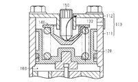
- Patent Document 1 describes an example of a pressure regulating valve that can be used in such a fuel injection system. That is, as shown in FIG. 8, the pressure regulating valve includes a housing 110.
- the housing 110 includes a cylindrical body 111 having openings at both ends in the axial direction (vertical direction in FIG. 8), and an upper portion of the cylindrical body 111. And a lid 112 that closes the opening.
- a piston 120 that moves forward and backward in the axial direction
- a spring 130 that applies a biasing force in a direction away from the lid 112 to the piston 120
- a spring receiving member 140 that supports the upper end of the spring 130.
- the lid body 112 supports the adjustment screw 150, and the adjustment screw 150 supports the spring receiving member 140 at its tip.
- the housing 110 is supported by the vehicle body. Therefore, vibration based on the pressure pulsation of the gaseous fuel is transmitted to the housing 110, and when the housing 110 vibrates, the vehicle body that supports the pressure regulating valve also vibrates.
- the phenomenon that the housing vibrates due to the pressure pulsation of the fluid downstream from the pressure regulating valve is not limited to the case where the pressure regulating valve is provided in the path for supplying the gaseous fuel. This may occur even when a pressure regulating valve is provided in the supply path for supply.
- An object of the present invention is to provide a pressure regulating valve that can suppress vibration of the housing caused by pressure pulsation of fluid generated on the downstream side.
- a pressure regulating valve for solving the above problems includes a cylindrical housing having a bottom wall, and a piston that is disposed in the housing and moves in the axial direction of the housing so as to approach and separate from the bottom wall.
- a spring that imparts an urging force in a direction away from the bottom wall to the piston, a spring receiving member that supports the spring, and a support member that is supported by the bottom wall and supports the spring receiving member.
- a pressure regulating valve that outputs an amount of fluid corresponding to the position of the piston in the axial direction of the housing, and is radially outer than the support member, and the bottom wall and the spring receiving member
- the vibration absorbing member is further provided at a position between the bottom wall and the spring receiving member.
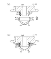
- (A) is sectional drawing which shows a mode before attaching a spring receiving member to a cover body in the pressure control valve of 1st Embodiment
- (b) is a pressure control valve of 1st Embodiment, and is attached to a cover body.
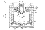
- FIG. 1 illustrates a pressure regulating valve 10 of the present embodiment.
- the pressure regulating valve 10 is provided in a supply path for supplying CNG (compressed natural gas), which is an example of gaseous fuel, to the internal combustion engine. That is, CNG output from the pressure regulating valve 10 is temporarily stored in the delivery pipe and supplied into the intake passage by driving the injection valve.
- CNG compressed natural gas
- the pressure adjusting unit 20 of the pressure adjusting valve 10 includes a body 21 and a cylindrical housing 22 fixed to the upper part of the body 21 in FIG.
- the housing 22 includes a cylindrical body 23 having openings at both ends in the axial direction Z (vertical direction in FIG. 1), and a lid body 24 that closes an opening at one end (upper end) of the cylindrical body 23 in the axial direction Z. ing. That is, in the pressure regulating valve 10 of this embodiment, the “bottom wall of the housing 22” is configured by the lid body 24. Note that the opening of the other end (lower end) in the axial direction Z of the cylindrical body 23 is closed by the body 21.
- the pressure regulating valve 10 of this embodiment includes an oil separator 11 that separates foreign substances such as oil from CNG.
- the oil separator 11 is fixed to the lower portion of the body 21 and separates foreign substances from the CNG that has been reduced to a specified pressure by the pressure adjusting unit 20.
- the CNG after the foreign matter is separated by the oil separator 11 is supplied downstream from the pressure regulating valve 10, that is, into the delivery pipe.
- the lid body 24 has a protruding portion 241 that protrudes in the axial direction Z toward the body 21.
- the lid 24 is provided with a support hole 242 extending in the axial direction Z.
- the support hole 242 opens to the outer surface (upper surface) of the lid body 24 and opens to the distal end surface (lower surface) of the protruding portion 241. That is, the projecting portion 241 has a support hole 242 that penetrates the lid body 24 in the axial direction Z, and has a cylindrical shape.
- the lid body 24 supports an adjustment screw 25 as a support member inserted into the support hole 242.
- the base end (upper end) of the adjustment screw 25 is positioned in the support hole 242, and the front end (lower end) of the adjustment screw 25 protrudes from the opening at the lower end of the support hole 242 toward the body 21.
- the adjustment screw 25 is screwed into the support hole 242, and the position of the tip of the adjustment screw 25 in the axial direction Z can be adjusted.
- a spring receiving member 26 supported by the tip of the adjustment screw 25 is provided.
- the spring receiving member 26 includes a spring receiving body 261 that is in contact with the tip of the adjustment screw 25 and an annular flange 263 that is connected to a radially outer end (peripheral edge) of the spring receiving body 261. is doing.
- the radially outer end of the spring receiver main body 261 is located in the axial direction Z between the proximal end and the distal end of the protruding portion 241 of the lid body 24, that is, between the upper end and the lower end of the protruding portion 241. Therefore, the flange 263 connected to the radially outer end of the spring receiving body 261 is also located between the base end and the distal end of the protrusion 241 of the lid 24 in the axial direction Z.
- Such a spring receiving body 261 has a cylindrical part (cylindrical part) 262 connected to the radially inner end of the flange 263.
- the inner diameter of the cylindrical portion 262 is larger than the outer diameter of the protruding portion 241 of the lid body 24.
- the gap between the cylindrical portion 262 and the protruding portion 241 is filled between the cylindrical portion 262 of the spring receiving member 26 and the protruding portion 241 of the lid 24.
- a vibration absorbing member 60 is provided on the surface.
- the vibration absorbing member 60 is in close contact (contact) with both the outer peripheral surface of the protruding portion 241 and the surface (inner peripheral surface) facing the outer peripheral surface of the protruding portion 241 in the cylindrical portion 262.
- the configuration of the vibration absorbing member 60 will be described later.
- a piston 27 that moves in a direction approaching the lid body 24 and a direction away from the lid body 24, that is, slides in the axial direction Z along the cylinder body 23.
- a pressure adjusting spring 28 is provided that applies an urging force to the piston 27 in a direction (downward) away from the lid body 24 of the housing 22.
- One end (upper end) in the axial direction Z of the pressure adjusting spring 28 is supported by the flange 263 of the spring receiving member 26.
- the space formed between the piston 27 and the body 21 is a pressure regulating chamber 29 that depressurizes high-pressure CNG to a specified pressure.
- the pressure regulating chamber 29 communicates with the delivery pipe through the oil separator 11, and the pressure in the pressure regulating chamber 29 is a pressure corresponding to the fuel pressure in the delivery pipe.
- the pressure in the pressure regulating chamber 29 is low, and as a result, the piston 27 is positioned near the body 21 in the axial direction Z.
- the pressure in the pressure regulating chamber 29 is high, and as a result, the piston 27 is located at a position away from the body 21 in the axial direction Z.
- a valve chamber 40 into which high-pressure CNG supplied from the fuel tank flows is provided in the body 21 .
- An intermediate portion 41 that opens to the upper surface of the body 21 and has a larger diameter than the valve chamber 40 is provided above the valve chamber 40 in the body 21.
- a partition member 42 that partitions the valve chamber 40 and the pressure regulating chamber 29 is provided in the intermediate portion 41.
- the partition member 42 is provided with a communication hole 421 that penetrates in the axial direction Z and allows the valve chamber 40 and the pressure regulating chamber 29 to communicate with each other.
- the valve body 43 of the pressure adjusting unit 20 includes a main body part 431 located in the valve chamber 40 and a rod part 432 extending from the main body part 431 to the inside of the pressure regulating chamber 29 through the communication hole 421.
- a valve chamber spring 44 that urges the main body 431 toward the partition member 42 is provided in the valve chamber 40 where the main body 431 is located.
- a communication path is provided for allowing CNG to flow from the valve chamber 40 into the pressure regulating chamber 29.
- the communication path is closed by the main body 431 of the valve body 43, and CNG does not flow from the valve chamber 40 into the pressure regulating chamber 29.
- the main body 431 of the valve body 43 is separated downward from the partition member 42, CNG flows from the valve chamber 40 into the pressure regulating chamber 29 through the communication path.
- the tip of the rod portion 432 is connected to the piston 27 through the connecting member 46. Therefore, when the piston 27 slides downward, the valve body 43 also moves downward, while when the piston 27 slides upward, the valve body 43 also moves upward. And if the main-body part 431 of the valve body 43 seats on the division member 42 and the opening of the communicating hole 421 is obstruct
- the vibration absorbing member 60 has a cylindrical shape extending in the axial direction Z, and is made of a resin such as silicone.
- the vibration absorbing member 60 includes a thick portion 61 having a large width (thickness) in the radial direction and a thin portion 62 having a width (thickness) in the radial direction narrower (smaller) than the thick portion 61,
- the thick part 61 and the thin part 62 are arranged in the axial direction Z.
- the vibration absorbing member 60 has a plurality (three in the example shown in FIG.
- the vibration absorbing member 60 is disposed between at least the two thick portions 61 and the two thick portions 61. And at least one thin portion 62.
- the long distance from the radially inner end to the radially outer end is referred to as “the width in the radial direction is wide”, and the distance from the radially inner end to the radially outer end. Is short, “the width in the radial direction is narrow”.
- the inner diameter of the thin portion 62 is equal to the inner diameter of the thick portion 61, while the outer diameter of the thin portion 62 is smaller than the outer diameter of the thick portion 61.
- the vibration absorbing member 60 has a constant inner diameter in the axial direction and has a plurality of annular ribs at different outer peripheral surface positions in the axial direction Z.
- the inner peripheral surface of the vibration absorbing member 60 is in close contact (contact) with the outer peripheral surface of the protruding portion 241 of the lid body 24. That is, the radially inner ends of both the thick portion 61 and the thin portion 62 are in close contact with the outer peripheral surface of the protruding portion 241.
- the radially outer end of each thick portion 61 is in close contact (contact) with the inner peripheral surface of the tubular portion 262 of the spring receiving member 26, while each thin portion 61 is thin.
- the radially outer end of the portion 62 is separated from the cylindrical portion 262.
- the radially outer end portion of the thin portion 62 is located radially inward from the inner peripheral surface of the cylindrical portion 262, and the radially outer end portion of the thin portion 62 and the inner peripheral surface of the cylindrical portion 262. There is a gap between them.
- the vibration absorbing member 60 is attached to the protruding portion 241 of the lid body 24. Thereby, the inner peripheral surface of the vibration absorbing member 60 is in close contact with the outer peripheral surface of the protruding portion 241. Then, as shown in FIG. 4B, the spring receiving member 26 is attached to the lid 24 in this state.
- the vibration absorbing member 60 includes not only the thick portion 61 that is in close contact with both the protruding portion 241 of the lid 24 and the cylindrical portion 262 of the spring receiving member 26, but also the thin portion 62 that does not contact the cylindrical portion 262.
- the contact area with the cylindrical portion 262 in the vibration absorbing member 60 is narrowed. That is, the sliding resistance when mounting the spring receiving member 26 is reduced. Therefore, the ease of attaching the spring receiving member 26 to the lid 24 is increased.
- the vibration absorbing member 60 is provided between the cylindrical portion 262 of the spring receiving member 26 and the protruding portion 241 of the lid 24. Since the vibration absorbing member 60 is in close contact with both the cylindrical portion 262 and the protruding portion 241, the spring receiving member 26 is difficult to be displaced in the radial direction and the axial direction Z. As a result, even if the spring receiving member 26 vibrates due to the pressure pulsation, the vibration of the spring receiving member 26 is attenuated by the vibration absorbing member 60. Thereby, the vibration attenuated by the vibration absorbing member 60 is transmitted to the adjustment screw 25 and the housing 22. That is, the vibration due to the pressure pulsation is not transmitted to the housing 22 so much, and the vibration of the housing 22 is reduced as compared with the case where the vibration absorbing member 60 is not provided.
- the housing 22 of the pressure regulating valve 10 is supported by the vehicle body. Therefore, if the vibration of the housing 22 is large, the vibration is easily transmitted to the vehicle body, and the vehicle occupant is likely to feel uncomfortable. However, in the pressure regulating valve 10 of the present embodiment, the housing 22 is less likely to vibrate by providing the vibration absorbing member 60. For this reason, vibration transmitted to the vehicle body via the housing 22 is also reduced.
- a vibration absorbing member 60 is provided between the lid 24 and the spring receiving member 26 so as to fill a gap between the lid 24 and the spring receiving member 26 of the housing 22. Therefore, when the pressure pulsation of the CNG is transmitted in the order of the piston 27, the pressure adjusting spring 28, the spring receiving member 26, the adjusting screw 25, and the housing 22, the vibration of the spring receiving member 26 caused by the pressure pulsation is a vibration absorbing member. Attenuated by 60. As a result, the vibration is hardly transmitted to the adjustment screw 25 and the housing 22. Therefore, the vibration of the housing 22 caused by the pressure pulsation of CNG generated downstream of the pressure regulating valve 10 can be suppressed.
- the vibration absorbing member 60 has an annular shape (endless shape). Therefore, even if the spring receiving member 26 vibrates in any direction, the vibration of the spring receiving member 26 can be attenuated by the vibration absorbing member 60.
- the vibration absorbing member 60 is a cylindrical member extending in the axial direction Z. Therefore, even if the position of the spring receiving member 26 in the axial direction Z is changed by the adjustment by the adjustment screw 25, the vibration absorbing member 60 and the spring receiving member 26 can be kept in close contact with each other. That is, the vibration damping effect of the spring receiving member 26 by the vibration absorbing member 60 can be stably exhibited.
- the thin portion 62 is in close contact with the protruding portion 241 of the lid 24, but is not in contact with the cylindrical portion 262 of the spring receiving member 26. For this reason, the contact area of the spring receiving member 26 with the vibration absorbing member 60 is reduced. That is, the sliding resistance received by the spring receiving member 26 when the spring receiving member 26 is attached to the lid 24 can be reduced as compared with the case where the vibration absorbing member having no thin portion 62 is employed. As a result, the ease of assembling the vibration absorbing member 60 to the spring receiving member 26 can be enhanced.
- the vibration absorbing member 60 has a plurality of thick portions 61 that are in close contact with both the projecting portion 241 of the lid body 24 and the cylindrical portion 262 of the spring receiving member 26. Therefore, it is possible to suppress the contact area between the vibration absorbing member 60 and the spring receiving member 26 from becoming too narrow as compared with the case where there is only one thick portion 61. As a result, the vibration of the spring receiving member 26 caused by the vibration absorbing member 60 can be appropriately damped.
- the vibration absorbing member 60 is made of resin, so that the resistance of the vibration absorbing member can be increased. Therefore, it is possible to make it difficult to cause an event in which the vibration damping effect of the spring receiving member 26 is reduced due to the damage of the vibration absorbing member.
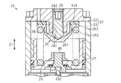
- the vibration absorbing member 60A has a disk shape.
- the vibration absorbing member 60 ⁇ / b> A is disposed between the flange 263 of the spring receiving member 26 and the lid body 24.
- the vibration absorbing member 60 ⁇ / b> A has a through hole, and the vibration absorbing member 60 ⁇ / b> A is disposed between the flange 263 and the lid body 24 with the protruding portion 241 of the lid body 24 being inserted into the through hole. Yes. That is, the gap between the flange 263 and the lid body 24 is filled with the vibration absorbing member 60A.
- the vibration absorbing member 60 ⁇ / b> A is in close contact (contact) with both the flange 263 and the lid body 24.
- the outer diameter of the vibration absorbing member 60 ⁇ / b> A is equal to the outer diameter of the pressure adjusting spring 28. Further, the inner diameter of the vibration absorbing member 60 ⁇ / b> A is smaller than the inner diameter of the pressure adjusting spring 28. Even in such a configuration, even if the pressure pulsation of CNG generated downstream of the pressure regulating valve 10 is transmitted to the spring receiving member 26 through the piston 27 and the pressure adjusting spring 28, the vibration of the spring receiving member 26 is not affected. It is suitably damped by the vibration absorbing member 60A. Therefore, the vibration of the housing 22 due to the pressure pulsation is reduced.
- the effect shown below can further be acquired.
- the vibration of the spring receiving member 26 accompanying expansion and contraction of the pressure adjusting spring 28 in the axial direction Z can be suitably damped by the vibration absorbing member 60A.
- each said embodiment into another embodiment as follows.
- the vibrational absorption member 60 is arrange
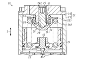
- the vibration absorbing member 60 may have a thin portion 62 that is in close contact (contact) with the cylindrical portion 262 but does not contact the protruding portion 241.
- the vibration absorbing member 60 may have a constant outer diameter in the axial direction, and may have a plurality of annular ribs at different positions on the inner peripheral surface in the axial direction Z.
- the contact portion of the protruding portion 241 with the vibration absorbing member 60 is reduced. Therefore, it is preferable to attach the spring receiving member 26 to the lid 24 after attaching the vibration absorbing member 60 to the spring receiving member 26. In this case, since the sliding resistance generated between the vibration absorbing member 60 and the protruding portion 241 when the spring receiving member 26 is mounted on the lid 24 is small, the mounting ease can be improved.
- the vibration absorbing member 60 has a plurality of thick portions 61. Therefore, it is possible to prevent the contact area between the protrusion 241 of the lid body 24 and the vibration absorbing member 60 from becoming too narrow. As a result, the vibration of the spring receiving member 26 can be appropriately damped by the vibration absorbing member 60.
- the vibration absorbing member 60 may be configured such that the thin portion 62 does not contact both the cylindrical portion 262 of the spring receiving member 26 and the protruding portion 241 of the lid 24.
- the inner diameter of the thin portion 62 is larger than the inner diameter of the thick portion 61
- the outer diameter of the thin portion 62 is smaller than the outer diameter of the thick portion 61.
- the vibration absorbing member 60 includes at least one of a cylindrical member main body, a protrusion protruding radially outward from the member main body, and a protrusion protruding radially inward from the member main body.
- the arrangement of the protrusions is not particularly limited.
- the protrusions may be arranged along the axial direction Z, or the protrusions may be arranged along the circumferential direction of the member body. May be.
- the vibrational absorption member 60 can be arrange
- the shape of the vibration absorbing member 60A may be changed as appropriate.
- the outer diameter of the vibration absorbing member 60 ⁇ / b> A may be larger than the outer diameter of the pressure adjusting spring 28.
- the inner diameter of the vibration absorbing member 60 ⁇ / b> A may be smaller than the inner diameter of the cylindrical portion 262 of the spring receiving member 26.
- the inner diameter of the vibration absorbing member 60 ⁇ / b> A may be equal to the inner diameter of the pressure adjusting spring 28.
- the vibration absorbing member 60A may not be annular.
- a plurality of vibration absorbing members 60A may be arranged along the circumferential direction.
- a vibration absorbing member made of a resin other than silicone is employed. May be.
- the vibration absorbing member may have any configuration as long as the vibration of the spring receiving member 26 can be attenuated.
- a configuration in which a liquid such as grease is sealed in a resin bag may be adopted as the vibration absorbing member.
- the pressure regulating valve is disposed in a path for supplying CNG, which is an example of a fluid, into the intake passage of the internal combustion engine, but is disposed in a path for supplying a gas other than CNG or a liquid such as oil. May be.
Landscapes
- Engineering & Computer Science (AREA)
- General Engineering & Computer Science (AREA)
- Physics & Mathematics (AREA)
- Mechanical Engineering (AREA)
- Fluid Mechanics (AREA)
- General Physics & Mathematics (AREA)
- Automation & Control Theory (AREA)
- Control Of Fluid Pressure (AREA)
- Safety Valves (AREA)
- Details Of Valves (AREA)
Abstract
圧力調整弁は、底壁を有する筒状のハウジングと、ハウジング内に配置される、底壁に対して接近及び離間するようにハウジングの軸方向に移動するピストンと、底壁から離れる方向への付勢力をピストンに付与するスプリングと、を備える。また圧力調整弁は、スプリングを支持するばね受け部材と、底壁に支持されているとともにばね受け部材を支持する支持部材と、を備え、ハウジングの軸方向におけるピストンの位置に応じた量の流体を出力する。圧力調整弁は、支持部材よりも径方向外側であって、且つ底壁とばね受け部材との間の位置に設けられ、底壁及びばね受け部材の双方に接触する振動吸収部材をさらに備える。
Description
本発明は、流体の供給経路に設けられている圧力調整弁に関する。
流体の一例である気体燃料を使用する内燃機関の燃料供給系には、燃料タンクから供給された気体燃料の圧力を減圧する圧力調整弁と、同圧力調整弁によって減圧された気体燃料が供給されるデリバリパイプと、デリバリパイプ内の気体燃料を噴射して吸気通路内に供給する噴射弁とが設けられている。
特許文献1には、こうした燃料噴射系に使用することのできる圧力調整弁の一例が記載されている。すなわち、図8に示すように、圧力調整弁はハウジング110を備えており、同ハウジング110は、軸方向(図8の上下方向)における両端に開口を有する筒体111と、筒体111の上部開口を閉塞する蓋体112とを有している。そして、ハウジング110内には、その軸方向に進退移動するピストン120と、蓋体112から離れる方向への付勢力をピストン120に付与するスプリング130と、スプリング130の上端を支持するばね受け部材140とが設けられている。また、蓋体112は調整スクリュ150を支持しており、調整スクリュ150はその先端でばね受け部材140を支持している。
こうした圧力調整弁にあっては、デリバリパイプ内の燃料圧力が低くなると、同デリバリパイプ内と連通する調圧室160内の圧力が低くなり、ピストン120が蓋体112から離れる方向に移動する。すると、圧力調整弁の開度が大きくなり、デリバリパイプ内への気体燃料の流出量が多くなる。一方、デリバリパイプ内の燃料圧力が高くなると、調圧室160内の圧力が高くなり、スプリング130からの付勢力に抗してピストン120が蓋体112に近づく方向に移動する。すると、圧力調整弁の開度が小さくなり、デリバリパイプ内への気体燃料の流出量が少なくなる。
ところで、噴射弁から気体燃料が噴射されると、デリバリパイプ内の燃料圧力が低下するものの、この低下分を補うように圧力調整弁を通じて気体燃料がデリバリパイプ内に供給される。そのため、噴射弁が間欠的に駆動しているときには、デリバリパイプ内では気体燃料の圧力脈動が発生し、同デリバリパイプ内と連通する調圧室160内でも気体燃料の圧力脈動が発生することとなる。こうした気体燃料の圧力脈動は、図8に実線の矢印で示すように、調圧室160を区画形成するピストン120、同ピストン120に接触しているスプリング130、同スプリング130を支持しているばね受け部材140、同ばね受け部材140を支持している調整スクリュ150、同調整スクリュ150を支持しているハウジング110の順に伝わる。
ここで、ハウジング110は、車体に支持されている。そのため、上記の気体燃料の圧力脈動に基づいた振動がハウジング110に伝わり、同ハウジング110が振動すると、圧力調整弁を支持する車体も振動してしまう。
なお、圧力調整弁よりも下流側の流体の圧力脈動に起因してハウジングが振動する事象は、気体燃料を供給する経路に圧力調整弁を設ける場合に限らず、気体燃料以外の他の流体を供給するための供給経路に圧力調整弁を設けた場合でも生じうる。
本発明の目的は、下流側で発生している流体の圧力脈動に起因するハウジングの振動を抑えることができる圧力調整弁を提供することにある。
上記課題を解決するための圧力調整弁は、底壁を有する筒状のハウジングと、前記ハウジング内に配置され、前記底壁に対して接近及び離間するように前記ハウジングの軸方向に移動するピストンと、前記底壁から離れる方向への付勢力を前記ピストンに付与するスプリングと、前記スプリングを支持するばね受け部材と、前記底壁に支持されているとともに前記ばね受け部材を支持する支持部材と、を備え、前記ハウジングの軸方向における前記ピストンの位置に応じた量の流体を出力する圧力調整弁において、前記支持部材よりも径方向外側であって、且つ前記底壁と前記ばね受け部材との間の位置に設けられ、前記底壁及び前記ばね受け部材の双方に接触する振動吸収部材をさらに備える。
(第1の実施形態)
以下、圧力調整弁10の一実施形態を図1~図4に従って説明する。
図1には、本実施形態の圧力調整弁10が図示されている。この圧力調整弁10は、気体燃料の一例であるCNG(圧縮天然ガス)を内燃機関に供給するための供給経路に設けられている。すなわち、圧力調整弁10から出力されたCNGは、デリバリパイプ内で一時的に貯留され、噴射弁の駆動によって吸気通路内に供給される。
以下、圧力調整弁10の一実施形態を図1~図4に従って説明する。
図1には、本実施形態の圧力調整弁10が図示されている。この圧力調整弁10は、気体燃料の一例であるCNG(圧縮天然ガス)を内燃機関に供給するための供給経路に設けられている。すなわち、圧力調整弁10から出力されたCNGは、デリバリパイプ内で一時的に貯留され、噴射弁の駆動によって吸気通路内に供給される。
図1に示すように、圧力調整弁10の圧力調整部20は、ボディ21と、ボディ21の図1の上部に固定されている筒状のハウジング22とを備えている。このハウジング22は、軸方向Z(図1の上下方向)における両端に開口を有する筒体23と、筒体23の軸方向Zにおける一端(上端)の開口を閉塞する蓋体24とを有している。すなわち、本実施形態の圧力調整弁10では、蓋体24により、「ハウジング22の底壁」が構成されている。なお、筒体23の軸方向Zにおける他端(下端)の開口は、ボディ21によって閉塞されている。
本実施形態の圧力調整弁10は、CNGからオイルなどの異物を分離するオイルセパレータ11を備えている。このオイルセパレータ11は、ボディ21の下部に固定されており、圧力調整部20によって規定圧に減圧されたCNGから異物を分離するようになっている。そして、オイルセパレータ11によって異物を分離した後の同CNGが圧力調整弁10よりも下流、すなわちデリバリパイプ内に供給されるようになっている。
次に、図1及び図2を参照し、圧力調整部20の構成について説明する。
図1及び図2に示すように、蓋体24は、ボディ21に向かって軸方向Zに突出する突出部241を有している。また、蓋体24には、軸方向Zに延びる支持用孔242が設けられている。この支持用孔242は、蓋体24の外面(上面)に開口するとともに、突出部241の先端面(下面)に開口している。すなわち、突出部241は、軸方向Zに蓋体24を貫通する支持用孔242を有し、円筒形状をなしている。そして、蓋体24は、支持用孔242に挿入された支持部材としての調整スクリュ25を支持している。この調整スクリュ25の基端(上端)は支持用孔242内に位置しており、調整スクリュ25の先端(下端)は、支持用孔242の下端の開口からボディ21に向かって突出している。なお、調整スクリュ25は、支持用孔242内に螺合されており、調整スクリュ25の先端の軸方向Zにおける位置は調整可能である。
図1及び図2に示すように、蓋体24は、ボディ21に向かって軸方向Zに突出する突出部241を有している。また、蓋体24には、軸方向Zに延びる支持用孔242が設けられている。この支持用孔242は、蓋体24の外面(上面)に開口するとともに、突出部241の先端面(下面)に開口している。すなわち、突出部241は、軸方向Zに蓋体24を貫通する支持用孔242を有し、円筒形状をなしている。そして、蓋体24は、支持用孔242に挿入された支持部材としての調整スクリュ25を支持している。この調整スクリュ25の基端(上端)は支持用孔242内に位置しており、調整スクリュ25の先端(下端)は、支持用孔242の下端の開口からボディ21に向かって突出している。なお、調整スクリュ25は、支持用孔242内に螺合されており、調整スクリュ25の先端の軸方向Zにおける位置は調整可能である。
また、ハウジング22内には、調整スクリュ25の先端で支持されているばね受け部材26が設けられている。このばね受け部材26は、調整スクリュ25の先端に接触しているばね受け本体261と、ばね受け本体261の径方向外側端部(周縁部)に接続されている円環状のフランジ263とを有している。ばね受け本体261の径方向外側端部は、軸方向Zにおいて蓋体24の突出部241の基端と先端との間、すなわち突出部241の上端と下端との間に位置している。そのため、ばね受け本体261の径方向外側端部に接続されているフランジ263もまた、軸方向Zにおいて蓋体24の突出部241の基端と先端との間に位置している。
こうしたばね受け本体261は、フランジ263の径方向内側端部に接続されている筒状部分(円筒状部分)262を有している。この筒状部分262の内径は、蓋体24の突出部241の外径よりも大きい。そして、本実施形態の圧力調整弁10では、ばね受け部材26の筒状部分262と蓋体24の突出部241との間に、筒状部分262と突出部241との間の隙間を埋めるように振動吸収部材60が設けられている。この振動吸収部材60は、突出部241の外周面と、筒状部分262において突出部241の外周面に対向する面(内周面)との双方に密接(接触)している。なお、振動吸収部材60の構成については後述する。
ハウジング22内には、蓋体24に近づく方向及び蓋体24から離れる方向に移動する、すなわち筒体23に沿って軸方向Zに摺動するピストン27が設けられている。またハウジング22内には、ハウジング22の蓋体24から離れる方向(下方)への付勢力をピストン27に付与する調圧用スプリング28が設けられている。この調圧用スプリング28の軸方向Zにおける一端(上端)が、ばね受け部材26のフランジ263によって支持されている。
ピストン27とボディ21との間に形成されている空間は、高圧のCNGを規定圧に減圧させる調圧室29である。この調圧室29内はオイルセパレータ11を通じて上記デリバリパイプ内と連通しており、調圧室29内の圧力は、上記デリバリパイプ内の燃料圧力に応じた圧力となる。そして、デリバリパイプ内の燃料圧力が低いときには、調圧室29内の圧力が低くなり、結果として、ピストン27が軸方向Zにおいてボディ21の近くに位置するようになる。一方、デリバリパイプ内の燃料圧力が高いときには、調圧室29内の圧力が高くなり、結果として、ピストン27が軸方向Zにおいてボディ21から離れた位置に位置するようになる。
ボディ21内には、燃料タンクから供給される高圧のCNGが流入する弁室40が設けられている。また、ボディ21において弁室40よりも上側には、ボディ21の上面に開口し、弁室40よりも大径の中間部41が設けられている。この中間部41内には、弁室40と調圧室29とを区画する区画部材42が設けられている。この区画部材42には、軸方向Zに貫通するとともに、弁室40と調圧室29とを連通させる連通孔421が設けられている。
圧力調整部20の弁体43は、弁室40内に位置する本体部431と、本体部431から連通孔421を通じて調圧室29内まで延びているロッド部432とを有している。そして、本体部431が位置する弁室40内には、本体部431を区画部材42に向けて付勢する弁室スプリング44が設けられている。
ロッド部432と、区画部材42における連通孔421の周壁との間には、弁室40から調圧室29内にCNGを流動させる連通路が設けられている。弁体43の本体部431が区画部材42に着座しているときには、連通路が弁体43の本体部431によって閉塞され、弁室40から調圧室29内にCNGが流れない。一方、弁体43の本体部431が区画部材42から下方に離れているときには、連通路を通じて弁室40から調圧室29内にCNGが流れるようになっている。
なお、ロッド部432の先端は、連結部材46を通じてピストン27に連結されている。そのため、ピストン27が下方に摺動しているときには弁体43もまた下方に移動する一方、ピストン27が上方に摺動しているときには弁体43もまた上方に移動するようになっている。そして、弁体43の本体部431が区画部材42に着座し、連通孔421の開口が閉塞されると、ピストン27は上方に摺動しない。すなわち、圧力調整部20の開度は、ピストン27の軸方向Zにおける位置に応じた開度となる。例えば、ピストン27が下方に摺動し、圧力調整部20の開度が大きくなると、圧力調整部20から出力されるCNGの量が多くなる。
次に、図3を参照し、振動吸収部材60の構成について説明する。
図3に示すように、振動吸収部材60は、軸方向Zに延びる円筒形状をなしており、シリコーンなどの樹脂によって構成されている。この振動吸収部材60は、径方向における幅の広い(厚みの大きい)肉厚部61と、径方向における幅(厚み)が肉厚部61よりも狭い(小さい)肉薄部62とを有し、肉厚部61と肉薄部62とが軸方向Zに並んでいる。本実施形態の圧力調整弁10では、振動吸収部材60は、複数(図3に示す例では3つ)の肉厚部61を有しており、軸方向Zに沿って肉厚部61と肉薄部62とが交互に配置されている。本実施形態のように肉厚部61と肉薄部62とが交互に配置される場合、振動吸収部材60は、少なくとも2つの肉厚部61と、2つの肉厚部61の間に配置される少なくとも1つの肉薄部62とを有する。なお、本明細書では、径方向内側端部から径方向外側端部までの距離が長いことを「径方向における幅が広い」といい、径方向内側端部から径方向外側端部までの距離が短いことを「径方向における幅が狭い」というものとする。
図3に示すように、振動吸収部材60は、軸方向Zに延びる円筒形状をなしており、シリコーンなどの樹脂によって構成されている。この振動吸収部材60は、径方向における幅の広い(厚みの大きい)肉厚部61と、径方向における幅(厚み)が肉厚部61よりも狭い(小さい)肉薄部62とを有し、肉厚部61と肉薄部62とが軸方向Zに並んでいる。本実施形態の圧力調整弁10では、振動吸収部材60は、複数(図3に示す例では3つ)の肉厚部61を有しており、軸方向Zに沿って肉厚部61と肉薄部62とが交互に配置されている。本実施形態のように肉厚部61と肉薄部62とが交互に配置される場合、振動吸収部材60は、少なくとも2つの肉厚部61と、2つの肉厚部61の間に配置される少なくとも1つの肉薄部62とを有する。なお、本明細書では、径方向内側端部から径方向外側端部までの距離が長いことを「径方向における幅が広い」といい、径方向内側端部から径方向外側端部までの距離が短いことを「径方向における幅が狭い」というものとする。
また、振動吸収部材60にあっては、肉薄部62の内径が肉厚部61の内径と等しい一方で、肉薄部62の外径が肉厚部61の外径よりも小さい。言い換えれば、本振動吸収部材60は、軸方向において一定の内径を有するとともに、軸方向Zにおいて互いに異なる外周面の位置に複数の環状のリブを有する。
そして、こうした振動吸収部材60の内周面は、蓋体24の突出部241の外周面に密接(接触)している。すなわち、肉厚部61及び肉薄部62の双方の径方向内側端部が突出部241の外周面に密接している。また、振動吸収部材60の外周側にあっては、各肉厚部61の径方向外側端部がばね受け部材26の筒状部分262の内周面に密接(接触)する一方で、各肉薄部62の径方向外側端部は筒状部分262から離れている。すなわち、肉薄部62の径方向外側端部は、筒状部分262の内周面よりも径方向内側に位置しており、肉薄部62の径方向外側端部と筒状部分262の内周面との間には隙間が介在している。
次に、図4(a)及び図4(b)を参照し、ハウジング22に振動吸収部材60及びばね受け部材26を組み付ける際の手順について説明する。
図4(a)に示すように、蓋体24の突出部241に振動吸収部材60が装着される。これにより、振動吸収部材60の内周面が突出部241の外周面に密接する。そして、図4(b)に示すように、この状態で蓋体24へのばね受け部材26の装着が行われる。振動吸収部材60は、蓋体24の突出部241及びばね受け部材26の筒状部分262の双方に密接する肉厚部61だけではなく、筒状部分262には接触しない肉薄部62を有する。そのため、振動吸収部材60が肉薄部62を有しない場合と比較し、振動吸収部材60における筒状部分262との接触領域が狭くなる。すなわち、ばね受け部材26を装着する際の摺動抵抗が小さくなる。したがって、ばね受け部材26を蓋体24に装着する際の容易性が高くなっている。
図4(a)に示すように、蓋体24の突出部241に振動吸収部材60が装着される。これにより、振動吸収部材60の内周面が突出部241の外周面に密接する。そして、図4(b)に示すように、この状態で蓋体24へのばね受け部材26の装着が行われる。振動吸収部材60は、蓋体24の突出部241及びばね受け部材26の筒状部分262の双方に密接する肉厚部61だけではなく、筒状部分262には接触しない肉薄部62を有する。そのため、振動吸収部材60が肉薄部62を有しない場合と比較し、振動吸収部材60における筒状部分262との接触領域が狭くなる。すなわち、ばね受け部材26を装着する際の摺動抵抗が小さくなる。したがって、ばね受け部材26を蓋体24に装着する際の容易性が高くなっている。
次に、本実施形態の圧力調整弁10の作用について説明する。
上記噴射弁からCNGが間欠的に噴射されると、デリバリパイプ内ではCNGの圧力脈動が発生する。このように圧力調整弁10よりも下流でCNGの圧力脈動が発生すると、圧力調整部20の調圧室29でもCNGの圧力が脈動するようになる。その結果、こうした圧力脈動が、ピストン27、調圧用スプリング28、ばね受け部材26、調整スクリュ25、ハウジング22の蓋体24の順に伝達される。
上記噴射弁からCNGが間欠的に噴射されると、デリバリパイプ内ではCNGの圧力脈動が発生する。このように圧力調整弁10よりも下流でCNGの圧力脈動が発生すると、圧力調整部20の調圧室29でもCNGの圧力が脈動するようになる。その結果、こうした圧力脈動が、ピストン27、調圧用スプリング28、ばね受け部材26、調整スクリュ25、ハウジング22の蓋体24の順に伝達される。
本実施形態の圧力調整弁10では、ばね受け部材26の筒状部分262と蓋体24の突出部241との間に振動吸収部材60が設けられている。この振動吸収部材60は筒状部分262及び突出部241の双方に密接しているため、ばね受け部材26は径方向及び軸方向Zに変位しにくくなる。その結果、上記の圧力脈動に起因してばね受け部材26が振動しても、当該ばね受け部材26の振動が振動吸収部材60によって減衰される。これにより、振動吸収部材60によって減衰された振動が、調整スクリュ25及びハウジング22に伝わることとなる。すなわち、ハウジング22には上記の圧力脈動に起因する振動があまり伝達されなくなり、振動吸収部材60を設けない場合と比較し、ハウジング22の振動が小さくなる。
ここで、圧力調整弁10のハウジング22は、車体に支持されている。そのため、ハウジング22の振動が大きいと、当該振動が車体に伝わりやすくなり、車両の乗員が不快を覚えやすい。しかし、本実施形態の圧力調整弁10では、振動吸収部材60を設けることにより、ハウジング22が振動しにくくなっている。そのため、ハウジング22を介して車体に伝達される振動も小さくなる。
以上、上記構成及び作用によれば、以下に示す効果を得ることができる。
(1)ハウジング22の蓋体24とばね受け部材26との間の隙間を埋めるように、蓋体24とばね受け部材26との間に振動吸収部材60が設けられている。そのため、CNGの圧力脈動が、ピストン27、調圧用スプリング28、ばね受け部材26、調整スクリュ25、ハウジング22の順に伝わる際に、上記の圧力脈動に起因するばね受け部材26の振動が振動吸収部材60によって減衰される。その結果、調整スクリュ25及びハウジング22には、当該振動が伝わりにくくなる。したがって、圧力調整弁10よりも下流側で発生しているCNGの圧力脈動に起因するハウジング22の振動を抑えることができる。
(1)ハウジング22の蓋体24とばね受け部材26との間の隙間を埋めるように、蓋体24とばね受け部材26との間に振動吸収部材60が設けられている。そのため、CNGの圧力脈動が、ピストン27、調圧用スプリング28、ばね受け部材26、調整スクリュ25、ハウジング22の順に伝わる際に、上記の圧力脈動に起因するばね受け部材26の振動が振動吸収部材60によって減衰される。その結果、調整スクリュ25及びハウジング22には、当該振動が伝わりにくくなる。したがって、圧力調整弁10よりも下流側で発生しているCNGの圧力脈動に起因するハウジング22の振動を抑えることができる。
(2)振動吸収部材60は、環状(無端状)をなしている。そのため、ばね受け部材26がどのような方向に振動する場合であっても、振動吸収部材60によってばね受け部材26の振動を減衰させることができる。
(3)より具体的には、振動吸収部材60は、軸方向Zに延びる筒状部材である。そのため、調整スクリュ25による調整によってばね受け部材26の軸方向Zにおける位置が変わったとしても、振動吸収部材60とばね受け部材26との密接を維持することができる。すなわち、振動吸収部材60によるばね受け部材26の振動の減衰効果を安定して発揮させることができる。
(4)本実施形態の圧力調整弁10では、肉薄部62は、蓋体24の突出部241に密接している一方で、ばね受け部材26の筒状部分262には接触していない。そのため、ばね受け部材26における振動吸収部材60との接触領域が小さくなっている。すなわち、肉薄部62を有しない振動吸収部材を採用する場合と比較して、ばね受け部材26を蓋体24に装着させる際にばね受け部材26が受ける摺動抵抗を小さくすることができる。その結果、振動吸収部材60のばね受け部材26への組み付けの容易性を高めることができる。
(5)また、振動吸収部材60は、蓋体24の突出部241及びばね受け部材26の筒状部分262の双方に密接する肉厚部61を複数有している。そのため、肉厚部61が1つのみであるときと比較し、振動吸収部材60とばね受け部材26との接触面積が狭くなりすぎることを抑制することができる。その結果、振動吸収部材60によるばね受け部材26の振動を適切に減衰させることができる。
(6)振動吸収部材として、グリースなどの液体を樹脂製の袋内に封入したものを採用した場合、樹脂製の袋が破損した際には当該袋から液体が漏出し、ばね受け部材の振動の減衰効果が低下してしまうおそれがある。こうした振動吸収部材を採用した場合と比較し、本実施形態では振動吸収部材60を樹脂によって構成しているので、振動吸収部材の耐性を高くすることができる。そのため、振動吸収部材の破損に起因してばね受け部材26の振動の減衰効果が低下する事象を生じさせにくくすることができる。
(第2の実施形態)
次に、圧力調整弁10の第2の実施形態を図5に従って説明する。本実施形態の圧力調整弁10では、振動吸収部材の配置位置などが第1の実施形態と相違している。したがって、以下の説明においては、第1の実施形態と相違する部分について主に説明するものとし、第1の実施形態と同一の部材構成には同一符号を付して重複説明を省略するものとする。
次に、圧力調整弁10の第2の実施形態を図5に従って説明する。本実施形態の圧力調整弁10では、振動吸収部材の配置位置などが第1の実施形態と相違している。したがって、以下の説明においては、第1の実施形態と相違する部分について主に説明するものとし、第1の実施形態と同一の部材構成には同一符号を付して重複説明を省略するものとする。
図5に示すように、本実施形態の圧力調整弁10では、振動吸収部材60Aは、円盤状をなしている。そして、振動吸収部材60Aは、ばね受け部材26のフランジ263と蓋体24との間に配置されている。詳細には、振動吸収部材60Aは貫通孔を有し、その貫通孔に蓋体24の突出部241が挿通された状態で振動吸収部材60Aがフランジ263と蓋体24との間に配置されている。すなわち、フランジ263と蓋体24との間の隙間が、振動吸収部材60Aによって埋められている。振動吸収部材60Aは、フランジ263と蓋体24との双方に密接(接触)している。
図5に示す例では、振動吸収部材60Aの外径は、調圧用スプリング28の外径と等しい。また、振動吸収部材60Aの内径は、調圧用スプリング28の内径よりも小さい。
そして、こうした構成であっても、圧力調整弁10よりも下流で発生したCNGの圧力脈動がピストン27及び調圧用スプリング28を通じてばね受け部材26に伝達されても、当該ばね受け部材26の振動が振動吸収部材60Aによって好適に減衰される。そのため、上記の圧力脈動に起因するハウジング22の振動が小さくなる。
そして、こうした構成であっても、圧力調整弁10よりも下流で発生したCNGの圧力脈動がピストン27及び調圧用スプリング28を通じてばね受け部材26に伝達されても、当該ばね受け部材26の振動が振動吸収部材60Aによって好適に減衰される。そのため、上記の圧力脈動に起因するハウジング22の振動が小さくなる。
以上、上記構成及び作用によれば、上記第1の実施形態の効果(1),(2)及び(6)と同等の効果に加え、以下に示す効果をさらに得ることができる。
(7)調圧用スプリング28の軸方向Zへの伸縮を伴うばね受け部材26の振動を振動吸収部材60Aによって好適に減衰させることができる。
(7)調圧用スプリング28の軸方向Zへの伸縮を伴うばね受け部材26の振動を振動吸収部材60Aによって好適に減衰させることができる。
なお、上記各実施形態は以下のような別の実施形態に変更してもよい。
・第1の実施形態において、ばね受け部材26の筒状部分262と蓋体24の突出部241との間に振動吸収部材60が配置されているのであれば、振動吸収部材60の形状を適宜変更してもよい。例えば、図6に示すように、振動吸収部材60は、筒状部分262に密接(接触)する一方で突出部241に接触しない肉薄部62を有する構成であってもよい。言い換えれば、振動吸収部材60は、軸方向において一定の外径を有するとともに、軸方向Zにおいて互いに異なる内周面の位置に複数の環状のリブを有してもよい。この場合、肉薄部62を有しない振動吸収部材と比較し、突出部241における振動吸収部材60との接触部分が小さくなる。そのため、振動吸収部材60をばね受け部材26に装着した後に、ばね受け部材26を蓋体24に装着するようにすることが好ましい。この場合、ばね受け部材26を蓋体24に装着する際における振動吸収部材60と突出部241との間で発生する摺動抵抗が小さいため、装着の容易性を高めることができる。
・第1の実施形態において、ばね受け部材26の筒状部分262と蓋体24の突出部241との間に振動吸収部材60が配置されているのであれば、振動吸収部材60の形状を適宜変更してもよい。例えば、図6に示すように、振動吸収部材60は、筒状部分262に密接(接触)する一方で突出部241に接触しない肉薄部62を有する構成であってもよい。言い換えれば、振動吸収部材60は、軸方向において一定の外径を有するとともに、軸方向Zにおいて互いに異なる内周面の位置に複数の環状のリブを有してもよい。この場合、肉薄部62を有しない振動吸収部材と比較し、突出部241における振動吸収部材60との接触部分が小さくなる。そのため、振動吸収部材60をばね受け部材26に装着した後に、ばね受け部材26を蓋体24に装着するようにすることが好ましい。この場合、ばね受け部材26を蓋体24に装着する際における振動吸収部材60と突出部241との間で発生する摺動抵抗が小さいため、装着の容易性を高めることができる。
また、上記振動吸収部材60は、複数の肉厚部61を有している。そのため、蓋体24の突出部241と振動吸収部材60との接触面積が狭くなりすぎることを抑制することができる。その結果、ばね受け部材26の振動を振動吸収部材60によって適切に減衰させることができる。
・第1の実施形態において、振動吸収部材60は、ばね受け部材26の筒状部分262と蓋体24の突出部241との双方に肉薄部62が接触しない構成であってもよい。この場合、肉薄部62の内径は肉厚部61の内径よりも大きく、肉薄部62の外径は肉厚部61の外径よりも小さくなることとなる。
・第1の実施形態において、振動吸収部材60は、円筒形状をなす部材本体と、同部材本体から径方向外側に突出する突起及び同部材本体から径方向内側に突出する突起のうち少なくとも一方を有する構成であってもよい。上記突起の配置は、特に限定されるものではなく、例えば該突起が軸方向Zに沿って並んで配置されていてもよいし、該突起が部材本体の周方向に沿って並んで配置されていてもよい。
・第1の実施形態において、ばね受け部材26の筒状部分262と蓋体24の突出部241との間に振動吸収部材60を配置することができるのであれば、振動吸収部材60は環状でなくてもよく、また複数の振動吸収部材から構成されていてもよい。例えば、軸方向Zに延びる短冊状の複数の振動吸収部材60を、周方向に沿って並ぶように配置してもよい。
・第2の実施形態において、振動吸収部材60Aの形状を適宜変更してもよい。例えば、図7に示すように、振動吸収部材60Aの外径を、調圧用スプリング28の外径よりも大きくしてもよい。また、振動吸収部材60Aの内径を、ばね受け部材26の筒状部分262の内径よりも小さくしてもよい。また、振動吸収部材60Aの内径を、調圧用スプリング28の内径と等しくしてもよい。
・第2の実施形態において、ばね受け部材26のフランジ263と蓋体24との間に振動吸収部材60Aを配置することができるのであれば、振動吸収部材60Aは環状でなくてもよい。例えば、複数の振動吸収部材60Aを、周方向に沿って配置するようにしてもよい。
・各実施形態において、圧力調整弁10よりも下流で発生した圧力脈動に起因するばね受け部材の振動を抑えることができるのであれば、シリコーン以外の他の樹脂で構成した振動吸収部材を採用してもよい。
・振動吸収部材は、ばね受け部材26の振動を減衰させることができるのであれば、任意の構成であってもよい。例えば、グリースなどの液体を樹脂製の袋内に封入した構成のものを振動吸収部材として採用してもよい。
・各実施形態では、圧力調整弁を、流体の一例であるCNGを内燃機関の吸気通路内に供給する経路に配置したが、CNG以外の他の気体やオイルなどの液体を供給する経路に配置してもよい。
Claims (8)
- 底壁を有する筒状のハウジングと、
前記ハウジング内に配置され、前記底壁に対して接近及び離間するように前記ハウジングの軸方向に移動するピストンと、
前記底壁から離れる方向への付勢力を前記ピストンに付与するスプリングと、
前記スプリングを支持するばね受け部材と、
前記底壁に支持されているとともに前記ばね受け部材を支持する支持部材と、を備え、
前記ハウジングの軸方向における前記ピストンの位置に応じた量の流体を出力する圧力調整弁において、
前記支持部材よりも径方向外側であって、且つ前記底壁と前記ばね受け部材との間の位置に設けられ、前記底壁及び前記ばね受け部材の双方に接触する振動吸収部材をさらに備える
圧力調整弁。 - 前記振動吸収部材は、環状をなしている
請求項1に記載の圧力調整弁。 - 前記ハウジングの前記底壁は、前記ピストンに向かって前記軸方向に突出する突出部を有するとともに、前記底壁を前記軸方向に貫通し且つ前記突出部の先端に開口する支持用孔を有し、
前記支持部材は、その先端が前記支持用孔から前記ピストンに向かって突出する態様で前記底壁に支持されており、
前記ばね受け部材は、
前記支持部材の先端に接触するばね受け本体であって、前記突出部の先端よりも前記軸方向において前記底壁の近くに位置する径方向外側端部を有する前記ばね受け本体と、
前記径方向外側端部に接続され、前記スプリングを支持する環状のフランジと、を有し、
前記振動吸収部材は、前記軸方向に延びる筒状部材であり、前記ハウジングの前記突出部の外周面と、前記ばね受け本体において同突出部の外周面に対向する面との双方に接触している
請求項1又は請求項2に記載の圧力調整弁。 - 前記振動吸収部材は、径方向における幅が広い肉厚部と、径方向における幅が同肉厚部よりも狭い肉薄部とを有し、前記肉厚部と前記肉薄部とは前記軸方向に並んでおり、
前記肉厚部は、前記ハウジングの前記突出部と前記ばね受け部材の前記ばね受け本体との双方に接触し、
前記肉薄部は、前記突出部及び前記ばね受け本体の何れか一方のみに接触している
請求項3に記載の圧力調整弁。 - 前記振動吸収部材は、径方向における幅が広い少なくとも2つの肉厚部と、径方向における幅が同肉厚部よりも狭い少なくとも1つの肉薄部とを有し、前記軸方向に沿って前記肉厚部と前記肉薄部とが交互に配置されており、
前記肉厚部は、前記ハウジングの前記突出部と前記ばね受け部材の前記ばね受け本体との双方に接触し、
前記肉薄部は、前記突出部及び前記ばね受け本体の何れか一方のみに接触している
請求項3に記載の圧力調整弁。 - 前記振動吸収部材は、筒状の部材本体を有するとともに、同部材本体から径方向外側に突出する突起及び同部材本体から径方向内側に突出する突起のうち少なくとも一方を有する
請求項3に記載の圧力調整弁。 - 前記ばね受け部材は、前記支持部材の先端に接触するばね受け本体と、同ばね受け本体の径方向外側端部に接続され、前記スプリングを支持する環状のフランジと、を有し、
前記振動吸収部材は、円盤状をなすとともに、前記ハウジングの底壁と前記フランジとの間に配置されており、
前記振動吸収部材の外径は前記スプリングの外径以上であり、前記振動吸収部材の内径は前記スプリングの内径以下である
請求項2に記載の圧力調整弁。 - 前記振動吸収部材は、樹脂によって構成されている
請求項1~請求項7のうち何れか一項に記載の圧力調整弁。
Applications Claiming Priority (2)
| Application Number | Priority Date | Filing Date | Title |
|---|---|---|---|
| JP2015080130A JP2016200947A (ja) | 2015-04-09 | 2015-04-09 | 圧力調整弁 |
| JP2015-080130 | 2015-04-09 |
Publications (1)
| Publication Number | Publication Date |
|---|---|
| WO2016163406A1 true WO2016163406A1 (ja) | 2016-10-13 |
Family
ID=57072330
Family Applications (1)
| Application Number | Title | Priority Date | Filing Date |
|---|---|---|---|
| PCT/JP2016/061278 Ceased WO2016163406A1 (ja) | 2015-04-09 | 2016-04-06 | 圧力調整弁 |
Country Status (2)
| Country | Link |
|---|---|
| JP (1) | JP2016200947A (ja) |
| WO (1) | WO2016163406A1 (ja) |
Cited By (1)
| Publication number | Priority date | Publication date | Assignee | Title |
|---|---|---|---|---|
| CN110776967A (zh) * | 2019-11-13 | 2020-02-11 | 宁波镇海合冰能源技术有限公司 | 一种液态天然气分离回收装置 |
Citations (3)
| Publication number | Priority date | Publication date | Assignee | Title |
|---|---|---|---|---|
| JP2000276236A (ja) * | 1999-03-24 | 2000-10-06 | Nippon Carbureter Co Ltd | 圧力調整器 |
| JP2011108057A (ja) * | 2009-11-19 | 2011-06-02 | Jtekt Corp | 減圧弁 |
| JP2015118411A (ja) * | 2013-12-16 | 2015-06-25 | 株式会社不二工機 | 減圧弁及びそれに用いられる開口間シール部材 |
-
2015
- 2015-04-09 JP JP2015080130A patent/JP2016200947A/ja not_active Ceased
-
2016
- 2016-04-06 WO PCT/JP2016/061278 patent/WO2016163406A1/ja not_active Ceased
Patent Citations (3)
| Publication number | Priority date | Publication date | Assignee | Title |
|---|---|---|---|---|
| JP2000276236A (ja) * | 1999-03-24 | 2000-10-06 | Nippon Carbureter Co Ltd | 圧力調整器 |
| JP2011108057A (ja) * | 2009-11-19 | 2011-06-02 | Jtekt Corp | 減圧弁 |
| JP2015118411A (ja) * | 2013-12-16 | 2015-06-25 | 株式会社不二工機 | 減圧弁及びそれに用いられる開口間シール部材 |
Cited By (1)
| Publication number | Priority date | Publication date | Assignee | Title |
|---|---|---|---|---|
| CN110776967A (zh) * | 2019-11-13 | 2020-02-11 | 宁波镇海合冰能源技术有限公司 | 一种液态天然气分离回收装置 |
Also Published As
| Publication number | Publication date |
|---|---|
| JP2016200947A (ja) | 2016-12-01 |
Similar Documents
| Publication | Publication Date | Title |
|---|---|---|
| JP6351336B2 (ja) | 緩衝器 | |
| JPWO2010126060A1 (ja) | 防振装置 | |
| JP2018013208A (ja) | 減衰力調整式緩衝器 | |
| US9566856B2 (en) | Fluid-filled vibration damping device | |
| JP2016200947A (ja) | 圧力調整弁 | |
| CN108138891A (zh) | 减振支承装置 | |
| CN111868410B (zh) | 阀座构件、阀和缓冲器 | |
| JP4976056B2 (ja) | 防振装置 | |
| JP2007278399A (ja) | 防振装置 | |
| WO2015064429A1 (ja) | 減圧弁 | |
| JP5280923B2 (ja) | 防振装置 | |
| JP5766136B2 (ja) | 燃料供給装置 | |
| JP5689645B2 (ja) | 防振装置 | |
| JP2021067295A (ja) | 流体封入式防振装置 | |
| JP2007239552A (ja) | 圧力脈動減衰装置 | |
| JP6391162B2 (ja) | 防振装置 | |
| JP5723944B2 (ja) | 防振装置 | |
| JP2016008709A (ja) | 防振装置 | |
| JP6388438B2 (ja) | 防振装置 | |
| JPWO2020050221A1 (ja) | 圧力調整バルブ | |
| JP5666331B2 (ja) | 燃料供給装置 | |
| JP2014084806A (ja) | 圧力調整弁装置 | |
| JP2007120563A (ja) | 防振装置 | |
| JP6584456B2 (ja) | 膨張弁 | |
| JP2007120566A (ja) | 防振装置 |
Legal Events
| Date | Code | Title | Description |
|---|---|---|---|
| 121 | Ep: the epo has been informed by wipo that ep was designated in this application |
Ref document number: 16776572 Country of ref document: EP Kind code of ref document: A1 |
|
| NENP | Non-entry into the national phase |
Ref country code: DE |
|
| 122 | Ep: pct application non-entry in european phase |
Ref document number: 16776572 Country of ref document: EP Kind code of ref document: A1 |