WO2016163373A1 - ガラス板 - Google Patents
ガラス板 Download PDFInfo
- Publication number
- WO2016163373A1 WO2016163373A1 PCT/JP2016/061180 JP2016061180W WO2016163373A1 WO 2016163373 A1 WO2016163373 A1 WO 2016163373A1 JP 2016061180 W JP2016061180 W JP 2016061180W WO 2016163373 A1 WO2016163373 A1 WO 2016163373A1
- Authority
- WO
- WIPO (PCT)
- Prior art keywords
- glass plate
- shape
- glass
- main surface
- orthogonal
- Prior art date
- Legal status (The legal status is an assumption and is not a legal conclusion. Google has not performed a legal analysis and makes no representation as to the accuracy of the status listed.)
- Ceased
Links
Images



Classifications
-
- C—CHEMISTRY; METALLURGY
- C03—GLASS; MINERAL OR SLAG WOOL
- C03B—MANUFACTURE, SHAPING, OR SUPPLEMENTARY PROCESSES
- C03B25/00—Annealing glass products
-
- C—CHEMISTRY; METALLURGY
- C03—GLASS; MINERAL OR SLAG WOOL
- C03B—MANUFACTURE, SHAPING, OR SUPPLEMENTARY PROCESSES
- C03B32/00—Thermal after-treatment of glass products not provided for in groups C03B19/00, C03B25/00 - C03B31/00 or C03B37/00, e.g. crystallisation, eliminating gas inclusions or other impurities; Hot-pressing vitrified, non-porous, shaped glass products
Definitions
- the present invention relates to a glass plate.
- glass plates have been widely used in various applications such as opening members such as windows and display members such as displays (see, for example, Patent Document 1).
- chemical strengthening and coating for the purpose of imparting functions and improving quality are increasing on glass plates.
- deformation does not remain even when a load is applied to the glass at a temperature below the strain point of the glass, but the internal stress due to external stress and temperature non-uniformity even at a temperature sufficiently lower than the strain point of the glass.
- the stress causes residual deformation that cannot be ignored in terms of product quality.
- not only the heat treatment step but also deformation may occur due to a load applied to the glass before and after the heat treatment or during the conveyance of the glass at a temperature of 100 ° C. or higher.
- an object of the present invention is to provide a glass plate with a small deformation amount that is generated when a load, heat, and temperature distribution are applied even if the plate thickness is thin.
- the glass plate of the present invention is a glass plate including two opposing main surfaces and end portions, and the first warped shape of the glass plate along any one direction in any one of the main surfaces.
- the curve formed by the first warped shape is curved in a convex shape
- the second warped shape of the glass plate along the orthogonal direction orthogonal to the one direction A glass plate in which the curve formed by the second warp shape is curved in a concave shape.
- the minimum value of the shape characteristic index Rs obtained by dividing the smaller absolute value of a 1 and a 2 by the larger absolute value is ⁇ 0.15 or less
- x is the above-mentioned one
- y is a position in the height direction of the glass plate at the arbitrary position x.
- the orthogonal direction is defined in parallel with the line direction, and the one direction is defined in a direction orthogonal to the line direction.
- the thickness of the glass plate of the present invention is 1.5 mm or less.
- the glass plate of the present invention for example, is produced by a float process. As a result, a feature that the tin concentration differs between one surface of the glass plate and the other surface facing the glass plate appears.
- the glass plate of the present invention is a glass plate having a main surface and a back surface opposite to the main surface, the rectangular shape having a long side and a short side orthogonal to the long side in plan view.
- the glass plate When cut out as a glass plate, when viewed from the long side, the glass plate has a concave shape such that the central region of the main surface is lower in position than the peripheral region of the main surface, When viewed from the short side, the glass plate has a convex shape such that the central region of the main surface is higher in position than the peripheral region of the main surface.
- the present invention even when the plate thickness is thin, it is possible to reduce the amount of deformation that occurs when a load or heat / temperature distribution is applied.
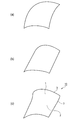
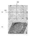
- FIG. 1 is a conceptual diagram showing three types of glass plates, (a) is a glass plate exhibiting a parabolic shape, (b) is a glass plate exhibiting a semi-cylindrical shape, and (c) Is a glass plate with a bowl shape 2 is a contour map of the glass plate shown in FIG. 1 (a), (a) is a plan view of the contour map, and (b) is a perspective view of the contour map.
- FIG. 3 is a graph showing an equation obtained by quadratic approximation of the surface shape of the glass plate of FIG. 4 is a contour map of the glass plate shown in FIG. 1B, FIG. 4A is a plan view of the contour map, and FIG. 4B is a perspective view of the contour map.
- FIG. 3 is a graph showing an equation obtained by quadratic approximation of the surface shape of the glass plate of FIG. 4 is a contour map of the glass plate shown in FIG. 1B
- FIG. 4A is a plan view of the contour map
- FIG. 5 is a graph showing an equation obtained by quadratic approximation of the surface shape of the glass plate of FIG.
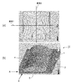
- FIG. 6 is a contour map of the glass plate shown in FIG. 1 (c), (a) is a plan view of the contour map, and (b) is a perspective view of the contour map.
- FIG. 7 is a graph showing an equation obtained by quadratic approximation of the surface shape of the glass plate of FIG.
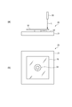
- FIGS. 8A and 8B are conceptual diagrams of a flat warping measuring instrument that measures the amount of deformation of its own weight.
- FIG. 8A is a side view
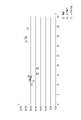
- FIG. FIG. 9 is a graph showing the measurement results of the initial warpage amount and the deflection amount of the glass plate.
- FIG. 1 shows the shape classification of the glass plate found by the present inventors.
- the glass plate is rarely formed into a perfect planar shape, and is generally formed into patterns of several shapes.
- FIG. 1A is a glass plate having a shape in which the central region is swollen and convex in the plane of the glass plate as compared with the peripheral region, and is a parabolic type, dome roof type, dish type, bowl type, etc. It exhibits such a shape.
- FIG. 1B shows a glass plate having a shape in which the center line region is swollen and convex as compared with the peripheral region, and has a shape such as a semi-cylindrical shape, a D shape, and a saddle shape.
- FIG.1 (c) is a glass plate which exhibits the shape like a heel placed on the back of a horse.
- FIGS. 1A, 1B, and 1C are glass plates having the shape shown in FIG. 1 (a) or FIG. 1 (b), and has the shape shown in FIG. 1 (c). Succeeded in producing glass plates.
- FIGS. 1A, 1B, and 1C will be described in detail with reference to FIGS.
- FIG. 2 is a contour map of the glass plate shown in FIG. 1 (a).
- This shape is called “parabolic shape” and has a shape similar to a curved surface of a part of a parabolic antenna. . From another viewpoint, it is similar to the shape of a dome roof, similar to the shape of a curved surface obtained by turning over a plate or bowl, and is a convex shape with the convex surface on top.
- One plane of the contour map corresponds to one plane in the glass plate, and the height of the contour map corresponds to the height (position in the thickness direction) of the glass plate.
- a method for examining the shape of the glass plate there is a method for examining the cross-sectional shape of each of two cross sections (cross section 1 and cross section 2) orthogonal to each other.
- x is an arbitrary position in the glass plate on the cross section 1 or the cross section 2
- y is a position in the height direction (thickness direction) of the glass plate at the arbitrary position x.
- y corresponds to a so-called warpage value.
- a, b, and c are arbitrary values according to the shape of the glass plate.
- cross-section 2 is a cross-section that passes along the highest position when the convex surface is raised in the cut-out rectangular glass plate while being along the grid direction parallel to the direction in which the glass plate material flows during manufacturing. Thus, a cross-sectional shape in the direction of the streak is obtained.
- the cross section 1 is a cross section orthogonal to the cross section 2 while passing through the highest position, and a cross sectional shape in the orthogonal direction orthogonal to the streak direction is obtained.
- the two cross-sectional shapes are represented by the following equations.
- the horizontal axis is x
- the vertical axis is y
- the unit is micron ( ⁇ m) on the vertical axis
- millimeter (mm) is on the horizontal axis.
- a shape characteristic index Rs indicating the characteristics of the glass plate is obtained.
- the coefficient a (a 1 and a 2 ) of the secondary term x 2 and, in turn, the shape characteristic index Rs obtained from the coefficient a can be used as a value for determining the shape type of the glass plate.
- FIG. 4 is a contour map of the glass plate shown in FIG. 1 (b), and this shape is called “semi-cylindrical shape”. It is similar to the shape of a ridge placed on a D-type plate.
- FIG. 6 is a contour map of the glass plate 10 shown in FIG. 1 (c), and this shape is called a “saddle shape”.
- the glass plate 10 has a shape of a saddle that can be placed on the back of a horse.
- the glass plate 10 has a shape of an anticlastic surface in which surfaces having opposite curvatures in different directions through arbitrary points are combined.
- FIG. 6 and FIG. 7 have a bowl shape, and the shape will be described in detail.
- the glass plate 10 includes a main surface (main surface) 1 and a back surface (main surface) 2 facing the main surface, and further a main surface 1 and a back surface 2 (two opposite surfaces). And the end 3 constituting the side when the glass plate 10 is viewed in plan view.
- the 1st curvature shape of the glass plate 10 was measured along arbitrary one directions inside any one main surface 1 and 2, it was 1st.
- the curve formed by the warp shape of 1 is curved into a convex shape.
- the graph indicating the curve formed by the first shape is curved in a convex shape.
- the curve formed by the second warpage shape is curved in a concave shape. For example, as shown in FIG.
- the graph indicating the curve formed by the second shape is curved in a downward convex shape, that is, a concave shape.
- the glass plate 10 has a bowl shape as a whole.
- the glass plate 10 the minimum value of a 1 and the absolute value of smaller absolute value of greater obtained by dividing the value shape characteristic indicators Rs of a 2 is -0.15 or less.
- orthogonal direction mentioned above is defined in parallel with the line direction, and one direction is defined as a direction orthogonal to the line direction.
- the glass plate 10 may be cut out as a rectangular glass plate having a long side 4 and a short side 5 orthogonal to the long side 4 in plan view.
- the central region of the main surface 1 when viewed from the direction along the short side 5, that is, from the long side 4 side (the direction of arrow A in FIG. 6B), the central region of the main surface 1 is the periphery of the main surface 1 in the long side 4 direction. It has a concave shape whose position is lower than that of the region.
- the central region of the main surface 1 is the peripheral region of the main surface 1 in the short side 5 direction. It is a convex shape whose position is higher than
- the central area cools relatively slowly as compared to the peripheral area during cooling, and the peripheral area cools earlier and is relatively quick relative to the central area. Since it reaches room temperature, the subsequent shrinkage becomes faster.
- either the central region or the peripheral region passes through a convex shape like a bowl, and there is a high possibility that the convex deformation remains. Or possibility that the original convex shape will be encouraged becomes high. Therefore, the glass plate having the shape shown in FIGS. 2 to 5 is easily manufactured.
- FIGS. 6 and 7 the situation in which FIGS. 6 and 7 (saddle type) are produced is that the deformation direction in one direction (for example, the width direction in the plane) near the strain point is the temperature difference between the front and back of the glass plane near the strain point. This can occur when the warp direction is different from the warp direction caused by the difference in shrinkage between the front and back surfaces. Also, for example, at the time of cooling in the heat treatment step below the vicinity of the strain point, by slowing down the cooling of the peripheral region, the movement of contracting relative to the central region is delayed, and the peripheral region is relatively relative to the central region. When passing through a state where the volume is large, the surrounding region is bent and becomes a saddle type state. As a result, the bowl shape tends to remain. There are many methods for controlling these shapes, and it is possible to obtain a preferable saddle shape by a method other than those shown here as an application within the applicable range of the present invention.
- the glass plate tends to cool from the surrounding area, and in this case, the deformation of the bowl-shaped plate is already the reverse process of the bowl-shaped generation direction, and the deformation occurs. Since the direction is to be corrected, the deformation remains in a shape that hardly remains or becomes flat in the absorption range depending on the size of the saddle shape.
- the saddle-shaped characteristic is that the volume of the plate is surplus in the surrounding area, so it is in a compressed state, and is deformed in a direction that causes further compression (for example, bowl-shaped (Deformation to become).
- the thickness of the glass plate of the present invention is not particularly limited.
- the bending stiffness of the material (hardness to bend: Young's modulus x cross-sectional second moment) is proportional to the cube of the plate thickness, and the thinner the glass plate, the easier it is to deform and the warpage becomes a problem. The thinner the glass plate, the more beneficial the effect of the present invention.
- the thickness of the glass plate is 0.7 mm or less, 0.45 mm or less, 0.4 mm or less, 0.3 mm or less, 0.2 mm or less.
- the thickness of the glass plate is preferably 0.05 mm or more.
- the glass plate is placed vertically, and the initial warp amount, which is a warp inherent in the glass plate, is measured using a general vertical warp measuring instrument in a state where the glass plate is not deformed by its own weight.
- the amount of deflection due to its own weight is measured using a flat warpage measuring instrument 20 shown in FIG. 8, the glass plate 10 is disposed on the surface plate 21 via the washer 22, and the total amount of deformation at the time of adding the own weight when the own weight is added is measured from the laser emitting device 30. Measure at L.
- the original amount of deflection (warp) is measured from (total deformation amount when self weight is added ⁇ initial warp amount).
- the washer 22 having an inner diameter of 6.8 mm, an outer diameter of 12.7 mm, and a thickness of 1 mm can be used, but is not particularly limited.
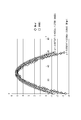
- FIG. 9 is a graph comparing deformation amounts of the bowl-shaped, bowl-shaped, and bowl-shaped glass plates.
- the horizontal axis x is the initial warpage when measured with a vertical warpage measuring instrument (not shown), and the vertical axis y is the amount of deflection when measured with the flat warping measuring instrument shown in FIG. -Initial warpage amount), the unit is ⁇ m. Specific values are shown in the table below.
- the saddle type has a smaller amount of deflection even if the initial warpage amount is larger than the bowl type and the saddle type. That is, in the case of a saddle type, the amount of warpage (warpage) is suppressed as the initial warpage amount is larger. In particular, for example, when the initial warpage amount is 10 ⁇ m or more in the sample size of this time, it is understood that the bending amount is strongly suppressed in the vertical shape.
- the glass plate of the present invention is preferably manufactured by a float forming method, but the manufacturing method is not particularly limited.
- the glass plate can be formed by a downdraw method, an overflow downdraw method, a slot downdraw method, a rollout method, an updraw method, or the like.
- the composition of the glass is not particularly limited. For example, although the above test was performed with an aluminosilicate glass plate, the composition of the glass is not limited to a specific one.
- the size of the glass plate used in the above test is a so-called G5 size (1300 mm ⁇ 1100 mm) plate cut into 10 cm ⁇ 10 cm corners (squares), but the size is not particularly limited.
- the thickness of a glass plate is all 0.44 mm.
- an appropriate amount of various glass raw materials are prepared, heated and melted, then homogenized by defoaming or stirring, and formed into a plate shape by a well-known forming method such as a float method.
- a glass plate formed by the float process has a feature that the concentration of tin on one surface is different from the concentration of tin on the other surface because one surface is in contact with molten tin.
- the present invention can be manufactured.
- One method is to use a rare roll whose central diameter is thinner than both sides. And a glass plate is induced
- the temperature situation above the strain point keep the temperature of the lower part including the inside of the bath higher than that of the upper part, and keep the temperature of the lower face high in the thickness direction of the glass plate.
- a force that protrudes toward the upper surface side is generated, and a shape that protrudes toward the upper surface side occurs in the flow direction.
- a glass plate is formed in a continuous ribbon shape. If there is a non-uniform temperature distribution in the width direction or thickness direction of the ribbon during cooling of the glass ribbon, the glass cut out from the ribbon to each leaf will be warped.
- the glass wall thickness of the ribbon edge is relatively thick, and the temperature during cooling is high at the edge portion and low at the central portion.
- the glass ribbon that has passed near the strain point in this temperature distribution becomes a dome shape (dish shape) after cutting.
- a bowl-shaped glass plate can be produced by cooling the thick edge portion and keeping the center portion warm.
- the other method is to induce a ridge shape whose width direction is convex to the upper surface side in a general float, and keep the temperature on the upper surface side higher than the temperature on the lower surface side in the temperature range above the strain point, It is possible to manufacture a bowl-shaped glass plate.
- the glass used in the present invention is not particularly limited, but typically includes a glass plate made of soda lime silicate glass, aluminosilicate glass, borate glass, lithium aluminosilicate glass, or borosilicate glass. . Details of the composition of the glass are not particularly limited.
- the glass plate according to the present invention can be widely used in various applications such as an opening member such as a window and a display member such as a display.
Landscapes
- Chemical & Material Sciences (AREA)
- Engineering & Computer Science (AREA)
- Materials Engineering (AREA)
- Organic Chemistry (AREA)
- Physics & Mathematics (AREA)
- Thermal Sciences (AREA)
- Surface Treatment Of Glass (AREA)
- Re-Forming, After-Treatment, Cutting And Transporting Of Glass Products (AREA)
Abstract
相対する二つの主表面(1、2)と端部(3)とを含み、鞍型の形状を呈しているガラス板(10)である。いずれか一つの主表面内の任意の一方向に沿ってガラス板(10)の第1の反り形状を測定したときに、当該第1の反り形状がなす曲線が凸形状に湾曲している。一方向と直交する直交方向に沿ってガラス板(10)の第2の反り形状を測定したときに、当該第2の反り形状がなす曲線が凹形状に湾曲している。
Description
本発明は、ガラス板に関する。
従来、ガラス板は窓などの開口部材、ディスプレイなどの表示部材等、種々の用途において幅広く用いられている(例えば、特許文献1参照)。ここで、近年、ガラス板に、機能付与や品質向上を目的とした化学強化、コーティングなどが施されることが増えている。工業的には、ガラスの歪点以下の温度でガラスに荷重をかけても変形が残留しないと言われているが、ガラスの歪点より十分に低い温度でも外部応力や温度の不均一による内部応力により、製品の品質上は無視できない残留変形が生じてしまう。また、熱処理工程だけではなく、熱処理前後や100℃以上の温度下でガラスの搬送中にガラスに荷重がかかることにより、変形が生じる場合もある。
このような変形は、特にガラスの板厚が薄い場合において顕著である。
ガラスの百科事典、作花済夫編、朝倉書店(2007)
前記従来の問題点を鑑みて、本発明は、板厚が薄くとも、荷重や熱・温度分布を与えた時に発生する変形量の小さいガラス板を提供することを目的とする。
本発明者らは、上記従来の問題点を鑑みて鋭意研究を行った結果、ガラス板の形状に着目するに至った。そして、従来製造されていたガラス板は一般にドーム型(皿型)の形状を有しており、このことが荷重や熱・温度分布により発生する反りやたわみ等の変形量を大きくする要因となっていることを見出した。そして、本発明者らはさらに検討を重ねた結果、以下のガラス板によれば前記課題を解決できることを見出し、本発明を完成するに至った。
本発明のガラス板は、相対する二つの主表面と端部とを含むガラス板であり、いずれか一つの前記主表面内の任意の一方向に沿って当該ガラス板の第1の反り形状を測定したときに、当該第1の反り形状がなす曲線が凸形状に湾曲しており、かつ前記一方向と直交する直交方向に沿って当該ガラス板の第2の反り形状を測定したときに、当該第2の反り形状がなす曲線が凹形状に湾曲している、ガラス板である。
本発明のガラス基板の一態様として例えば、前記第1の反り形状がなす曲線を二次近似した場合における式が、y=a1x2+b1x+c1で表され(a1、b1、c1は任意の値)、前記第2の反り形状がなす曲線を二次近似した場合における式が、y=a2x2+b2x+c2で表され(a2、b2、c2は任意の値)、a1およびa2のうち絶対値の小さい値を絶対値の大きい値で除すことで得られる形状特性指標Rsの最小値が-0.15以下であり、xは前記一方向または前記直交方向における当該ガラス板内での任意の位置、yは当該任意の位置xにおけるガラス板の高さ方向の位置である。
本発明のガラス基板の一態様として例えば、前記直交方向が筋目方向と平行に定義され、前記一方向が前記筋目方向に直交する方向に定義される。
本発明のガラス板の一態様として例えば、厚みが1.5mm以下である。
本発明のガラス板の一態様として例えば、ガラス板はフロート法によって製造される。この結果、ガラス板の一方の面と対向する他方の面との間で、スズの濃度が異なるという特徴が表れる。
本発明のガラス板は、主面と前記主面に対向する裏面とを備えたガラス板であって、前記ガラス板を平面視で長辺と当該長辺に直交する短辺を備えた矩形のガラス板として切りだしたとき、前記長辺側から見た場合、前記ガラス板は、前記主面の中央領域が前記主面の周辺領域に比べて位置が低くなるような凹形状であり、前記短辺側から見た場合、前記ガラス板は、前記主面の前記中央領域が前記主面の前記周辺領域に比べて位置が高くなるような凸形状である。
本発明によれば、板厚が薄くとも、荷重や熱・温度分布を与えた時に発生する変形量を小さく抑えることが可能となる。
以下、本発明に係るガラス板の実施形態を、図面を参照しつつ詳述する。図1は本発明者が見出したガラス板の形状分類である。詳細に観察するとガラス板は完全な平面形状に成形されることは少なく、いくつかの形状のパターンに成形されるのが一般的である。
図1(a)は、ガラス板の平面内において、中心領域が周辺領域に比べ、膨らんで凸状態になっている形状のガラス板であり、パラボラ型、ドーム屋根型、皿型またはお椀型等の如き形状を呈するものである。図1(b)は、中心線領域が周辺領域に比べ、膨らんで凸状態になっている形状のガラス板であり、半円筒型、D型、蒲鉾型等の如き形状を呈するものである。図1(c)は、馬の背に乗せられる鞍の如き形状を呈するガラス板である。
本発明者は、従来から製造されていたガラス板のほとんどは、図1(a)または図1(b)に示す形状のガラス板であることを見出すとともに、図1(c)に示す形状のガラス板を製造することに成功した。図1(a)、(b)、(c)各々の形状について、図2~図7を用いて詳しく説明する。
図2は、図1(a)に示すガラス板の等高線図であり、この形状は、「パラボラ型(parabolic shape)」と呼ばれ、パラボラアンテナの一部の曲面に類似した形状を呈している。別の見方をすれば、ドーム屋根の形状に類似しているし、お皿やお椀をひっくり返して得られる曲面の形状に類似しており、凸面が上にある凸形状である。等高線図の一平面はガラス板内の一平面に対応し、等高線図の高さはガラス板の高さ(厚み方向の位置)に対応している。
ガラス板の形状を調べる方法として、ガラス板の互いに直交する二つの断面(断面1、断面2)各々における断面形状を調べる方法がある。この断面形状を二次近似した場合、一般式:y=ax2+bx+cで表される。ここでxは、断面1または断面2上でのガラス板内での任意の位置、yは当該任意の位置xにおけるガラス板の高さ方向(厚み方向)の位置である。yはいわゆる反りの値に対応する。a、b、cは、ガラス板の形状に応じた任意の値である。
二つの断面のうち、断面2は、製造時にガラス板の材料が流れる方向に平行な筋目方向に沿いつつ、切り出された矩形のガラス板内で凸面を上にした場合に最も高い位置を通る断面であり、筋目方向の断面形状が得られる。一方、断面1は、この最も高い位置を通りつつ、断面2に直交する断面であり、筋目方向に直交する直交方向の断面形状が得られる。
図3のグラフに示すように、光学干渉式測定器による測定の結果、本例のガラス板では、二つの断面形状は、以下の式で表されることがわかった。図3において横軸がx、縦軸がy、単位は縦軸がミクロン(μm)で横軸がミリメートル(mm)である。測定は平面が60mm×60mmの正方形で構成されるガラス板について行い、正方形の平面の一側面をxの基準位置(x=0)として測定を行った(後述する図5、図7も同じ)。
断面1:y=-0.0091x2+0.546x-3.2643
断面2:y=-0.0073x2+0.4352x-1.2758
断面2:y=-0.0073x2+0.4352x-1.2758
ここで、断面1の形状の式および断面2の形状の式の二次項x2の係数aについて、当該係数aの絶対値の小さい方の値を、絶対値の大きい方の値で除することにより、ガラス板の特性を示す形状特性指標Rsが得られる。例えば、断面1の形状(上述の直交方向における断面形状)を二次近似した場合における式が、y=a1x2+b1x+c1(a1、b1、c1は任意の値)で表され、断面2の形状(上述の筋目方向における断面形状)を二次近似した場合における式が、y=a2x2+b2x+c2(a2、b2、c2は任意の値)で表されると仮定する。|a1|>|a2|の場合、Rs=a2/a1となり、|a1|<|a2|の場合、Rs=a1/a2となる。
以下に述べる通り、二次項x2の係数a(a1およびa2)、ひいては係数aから求められる形状特性指標Rsを、ガラス板の形状の種類を判断する値として用いることができる。
図2、図3の例では、Rs=-0.0073/-0.0091≒0.81になる。そして、形状特性指標Rsが0.15以上の場合、当該ガラス板の形状は、お椀型に分類される。
図4は、図1(b)に示すガラス板の等高線図であり、この形状は、「半円筒型(semi-cylindrical shape)」と呼ばれる。D型、板に乗せられた蒲鉾の形状にも類似している。
図5のグラフに示すように、本例のガラス板では、二つの断面形状は以下の式で表されることがわかった。
断面1:y=-0.0038x2+0.2227x-2.2679
断面2:y=0.0005x2-0.0405x+1.6619
断面2:y=0.0005x2-0.0405x+1.6619
この例においては、Rs=0.0005/-0.0038≒-0.14になる。そして、形状特性指標Rsが、-0.15 < Rs < +0.15の範囲にある場合、当該ガラス板の形状は、蒲鉾型に分類される。
図6は、図1(c)に示すガラス板10の等高線図であり、この形状は、「鞍型(saddle shape)」と呼ばれる。ガラス板10は馬の背に乗せられる鞍の形状を呈している。より一般的な意味としては、ガラス板10は、任意の点を介して異なる方向に反対の曲率を有する面が複合したアンチクラスティック面(anticlastic surface)の形状を呈する。
図7のグラフに示すように、本例のガラス板10では、二つの断面形状は以下の式で表されることがわかった。
断面1:y=-0.0036x2+0.217x-2.8451
断面2:y=0.0018x2-0.1129x+2.3747
断面2:y=0.0018x2-0.1129x+2.3747
この例においては、Rs=0.0018/-0.0036≒-0.49になる。そして、形状特性指標Rsの最小値が-0.15以下の場合、当該ガラス板10の形状は、鞍型に分類される。図7のグラフから明らかなように、この鞍型の形状において、断面1と断面2は、ガラス板10の厚み方向において相反する方向に凸形状となっている。それぞれの型と形状特性指標Rsの関係を以下の表にまとめた。

図1(c)、図6、図7のガラス板10は鞍型の形状を呈するが、当該形状を詳細に説明する。図1(c)、図6に示すように、ガラス板10は、主面(主表面)1と当該主面に対向する裏面(主表面)2、さらに主面1および裏面2(相対する二つの主表面1、2ともいえる)の間に存在し、ガラス板10を平面視した場合の辺を構成する端部3を含む。
そして、図1(c)、図6に示すように、いずれか一つの主表面1、2の内部の任意の一方向に沿ってガラス板10の第1の反り形状を測定したときに、第1の反り形状がなす曲線が凸形状に湾曲している。例えば、図7に示したように断面1に沿った一方向において、第1の形状がなす曲線を示すグラフは凸形状に湾曲している。さらに、この一方向と直交する直交方向に沿ってガラス板10の第2の反り形状を測定したときに、第2の反り形状がなす曲線が凹形状に湾曲している。例えば、図7に示したように断面1に直交する断面2に沿った直交方向において、第2の形状がなす曲線を示すグラフは下側に凸形状、すなわち凹形状に湾曲している。この結果、ガラス板10は全体として鞍型の形状を呈している。
この場合、第1の反り形状がなす曲線を二次近似した場合における式が、y=a1x2+b1x+c1で表され(a1、b1、c1は任意の値)、第2の反り形状がなす曲線を二次近似した場合における式が、y=a2x2+b2x+c2で表される(a2、b2、c2は任意の値)。そして、ガラス板10において、a1およびa2のうち絶対値の小さい値を絶対値の大きい値で除すことで得られる形状特性指標Rsの最小値が-0.15以下である。
尚、上述した直交方向は筋目方向と平行に定義され、一方向が筋目方向に直交する方向に定義されている。
また、ガラス板10を平面視で長辺4と長辺4に直交する短辺5を備えた矩形のガラス板として切りだす場合がある。この場合、短辺5に沿った方向、すなわち長辺4側(図6(b)の矢印A方向)から見た場合、長辺4方向において、主面1の中央領域が主面1の周辺領域に比べて位置が低くなるような凹形状を呈する。また、長辺4に沿った方向、すなわち短辺5側(図6(b)の矢印B方向)から見た場合、短辺5方向において、主面1の中央領域が主面1の周辺領域に比べて位置が高くなるような凸形状である。
上述のような異なる型のガラス板が製造される理由について、以下説明する。例えば、歪み点以上の温度の熱処理を伴う工程を含むガラス板製造工程がある。当該工程において、歪み点付近の温度の場合にガラス平面の裏表に所定の温度差が生ずる場合、その後の冷却時の表裏での収縮量が異なることにより、図2~図5(お椀型および蒲鉾型)の形状のガラス板が製造される傾向がある。また、例えば歪み点付近以下の熱処理工程時には、ガラス板の平面における中心領域に多くの熱が蓄積する(中心領域の温度が高い)。一般的に、冷却時において、ガラス板は周辺領域から冷える傾向がある。したがって、中心領域に多くの熱が蓄積している場合、冷却時に中心領域の方が周辺領域に比べて相対的にゆっくり冷え、周辺領域の冷却が先行し、中心領域に対して相対的に早く室温に至るため、その後の収縮が速くなる。この過程で、お椀のように中心領域または周辺領域のどちらかが凸の形状を経由することになり、凸の変形が残留してしまう可能性が高くなる。または元々の凸の形状が助長される可能性が高くなる。よって、図2~図5の形状のガラス板が製造されやすい結果を招く。
一方、図6、図7のもの(鞍型)が作られる状況は歪み点付近での一方向(例えば平面における幅方向)に於ける変形方向が、歪み点付近のガラス平面の表裏の温度差を起因として、その後の表裏収縮差で起こる反り方向と異なる場合に起こり得る。また、例えば歪み点付近以下の熱処理工程の冷却時では、周辺領域の冷却を遅らすことにより、中心領域に対して相対的に収縮する動きが遅くなり、周辺領域が中心領域に対して相対的に体積が多い状態を経由すると周辺領域の撓みを作り出し鞍型状態になる。この結果、鞍型の形状が残留しやすい。尚、これらの形状を制御する方法は多くあり、此処に示した以外の方法で好ましい鞍型形状を得ることも本発明の適応範囲内の活用として可能である。
先述したように、一般的に、冷却時において、ガラス板は周辺領域から冷える傾向があり、この場合に既に鞍型の板の冷却時の変形は鞍型生成方向と逆の過程となり、変形を修正する方向になるため、鞍型の大きさの程度による吸収範囲で変形が残留しにくい又は平坦になっていく形状に変形が残留する。
また温度分布でない変形に対しても、鞍型の特性は周辺領域に板の体積が余剰であるため、圧縮された状況であり、更に圧縮される撓みを起こすような方向の変形(例えばお椀型になろうとする変形)に対して抵抗力をしめす。
よってお椀型や蒲鉾型の形状ではなく、鞍型のガラス板を製造することにより、得られるガラス板について、荷重や熱・温度分布を与えた時に発生する変形量を小さく抑えることが可能となり、好ましいガラス板を得ることができる。このような効果は特にガラス板の厚みが薄い場合に変形しやすいため発揮される(例えば厚みが1.5mm以下)。もちろん本発明のガラス板の厚みは特に限定されない。材料の曲げこわさ(曲がりにくさ:ヤング率×断面二次モーメント)は板厚の3乗に比例し、ガラス板の厚みが薄ければ薄いほどガラス板が変形しやすく反りが問題となるため、ガラス板の厚みが薄いほど本発明の効果が有益となる。具体的には、ガラス板の厚みが0.7mm以下、0.45mm以下、0.4mm以下、0.3mm以下、0.2mm以下などの場合に有益である。一方、ガラス板をカバーガラスとして用いた場合の実用性を考慮すると、ガラス板の厚みは、0.05mm以上が好ましい。
次に、上記のガラス板の変形量を評価する方法を説明する。まずガラス板を縦置きにし、自重で変形していない状態で、一般的な縦置き反り測定器を用いて、本来有する反りである初期反り量を測定する。次に、図8に示す平置き反り測定器20を用いて自重による撓み量を測定する。図8の平置き反り測定器20においては、定盤21上にワッシャー22を介してガラス板10を配置し、自重変形を付加したときの自重付加時総変型量をレーザー発射装置30からのレーザーLにて測定する。最後に(自重付加時総変形量-初期反り量)より、本来の撓み量(反り)を測定する。ワッシャー22は、例えば内径6.8mm、外径12.7mm、厚み1mmのものが使用され得るが特に限定はされない。
図9は、お椀型、蒲鉾型、鞍型各々のガラス板の変形量を比較したグラフである。横軸xが図示していない縦置き反り測定器で測定したときの初期反り量、縦軸yが図8で示した平置き反り測定器で測定したときの撓み量(自重付加時総変形量-初期反り量)であり、単位はμmである。下記の表に具体的な値を示す。
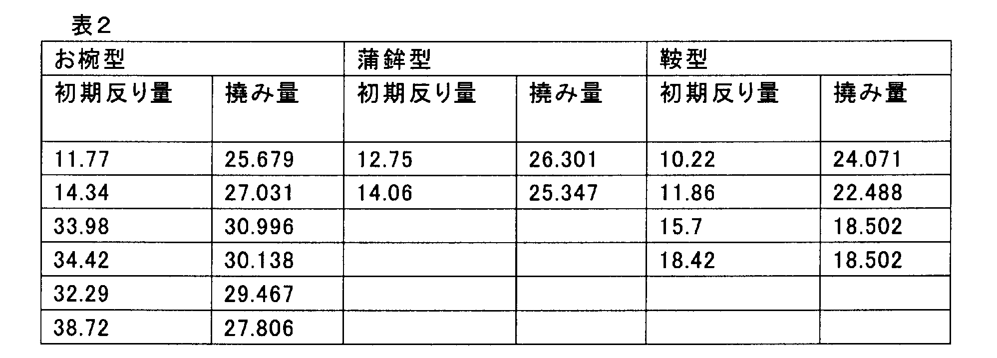
上記の評価結果から、鞍型の方が、お椀型および蒲鉾型に比べ、初期反り量が大きくても、撓み量が小さいことが理解される。すなわち、鞍型の場合、初期反り量が大きいほど、撓み量(反り)が抑制される。特に例えば今回のサンプルサイズにおいて初期反り量が10μm以上の場合、鞍型であると撓み量の抑制が強くなることが分かる。
下記で述べるように、本発明のガラス板は、好ましくはフロート成形法により製造されるが、製造方法は特に限定されない。ガラス板は、ダウンドロー法、オーバーフローダウンドロー法、スロットダウンドロー法、ロールアウト法、アップドロー法などによって成形することも可能である。またガラスの組成も特に限定はされない。例えば上記の試験はアルミノシリケートのガラス板により行われたが、ガラスの組成は、特定のものには限定されない。
上記の試験で用いられたガラス板の大きさは、いわゆるG5サイズ(1300mm × 1100mm)の板から、10cm×10cmの角(正方形)に切り出したものであるが、大きさは特に限定はされない。なお、ガラス板の厚みは、すべて0.44mmである。
以下、本発明のガラスを製造する方法について説明する。
本発明のガラスを製造する方法としては、例えば、種々のガラス原料を適量調合し、加熱溶融した後、脱泡または攪拌などにより均質化し、フロート法等の周知の成形方法により板状に成形し、徐冷後、所望のサイズに切断し、研磨加工を施して製造する方法が挙げられる。フロート法により成形されたガラス板は、一方の面が溶融スズに接しているため、当該一方の面のスズの濃度が他方の面のスズの濃度とは異なるという特徴がある。
このとき、例えば、フロート法を用いて板状に成形する場合においては(断面2は、フロートの筋目方向に沿うことになる)、例えば、以下のいずれかの手法を採用することにより、本発明のガラス板を製造することができる。
一つの方法は、中央の径が両サイドに比べて細いレアーロールを使用する方法である。そして、幅方向に上面側へ凹状である蒲鉾形状になるようにガラス板を誘導する。歪み点より上の温度状況で、バス内も含めて下部の温度を上部に比べて高めに保ち、ガラス板の厚み方向で下面の温度を高く保つ。この温度差の結果、ガラス板が冷却するにつれて、上面側へ凸になる力が発生し、流れ方向には上面側へ凸の形状が生じる。一方で先に示した幅方向に上面側に凹んだ蒲鉾形状が、この温度差による変形との相互作用で相殺され減衰されつつも幅方向の上面側へ凹状を残存させる程度に調整することで、鞍型のガラス板が製造される。
また、フロート法では連続するリボン形状でガラス板が成形される。ガラスリボンの冷却中にリボンの幅方向もしくは厚み方向で不均一な温度分布があると、リボンから毎葉に切り出したガラスに反りが発生する。特に薄いガラス板では、リボンエッジのガラス肉厚が相対的に厚くなり、冷却中の温度はエッジ部で高く中央部で低くなる。この温度分布で歪み点付近を経過したガラスリボンは切断後にドーム型(皿型)となる。一方で肉厚の厚いエッジ部を冷却し、中央部を保温することで鞍型のガラス板を製造することができる。
他の方法は、一般的なフロートでは幅方向が上面側へ凸の蒲鉾形状に誘導して、歪み点以上の温度域で、上面側の温度を下面側の温度よりも高めに保つことにより、鞍型のガラス板を製造することが可能である。
本発明に用いられるガラスは、特に限定されるものではないが、例えば、典型的にはソーダライムシリケートガラス、アルミノシリケートガラス、ボレートガラス、リチウムアルミノシリケートガラス、ホウ珪酸ガラスからなるガラス板が挙げられる。ガラスの組成の詳細も特に限定はされない。
尚、本発明は、上述した実施形態に限定されるものではなく、適宜、変形、改良、等が可能である。その他、上述した実施形態における各構成要素の材質、形状、寸法、数値、形態、数、配置箇所、等は本発明を達成できるものであれば任意であり、限定されない。
本出願は、2015年4月10日出願の日本特許出願、特願2015-080938に基づくものであり、その内容はここに参照として取り込まれる。
本発明に係るガラス板は、窓などの開口部材、ディスプレイなどの表示部材等、種々の用途において幅広く使用することが可能である。
1 主面(主表面)
2 裏面(主表面)
3 端部
4 長辺
5 短辺
10 ガラス板
20 平置き反り測定器
21 定盤
22 ワッシャー
30 レーザー発射装置
2 裏面(主表面)
3 端部
4 長辺
5 短辺
10 ガラス板
20 平置き反り測定器
21 定盤
22 ワッシャー
30 レーザー発射装置
Claims (6)
- 相対する二つの主表面と端部とを含むガラス板であり、
いずれか一つの前記主表面内の任意の一方向に沿って当該ガラス板の第1の反り形状を測定したときに、当該第1の反り形状がなす曲線が凸形状に湾曲しており、かつ、
前記一方向と直交する直交方向に沿って当該ガラス板の第2の反り形状を測定したときに、当該第2の反り形状がなす曲線が凹形状に湾曲している、ガラス板。 - 前記第1の反り形状がなす曲線を二次近似した場合における式が、y=a1x2+b1x+c1で表され(a1、b1、c1は任意の値)、
前記第2の反り形状がなす曲線を二次近似した場合における式が、y=a2x2+b2x+c2で表され(a2、b2、c2は任意の値)、
a1およびa2のうち絶対値の小さい値を絶対値の大きい値で除すことで得られる形状特性指標Rsの最小値が-0.15以下であり、
xは前記一方向または前記直交方向における当該ガラス板内での任意の位置、yは当該任意の位置xにおけるガラス板の高さ方向の位置である、請求項1に記載のガラス板。 - 前記直交方向が筋目方向と平行に定義され、前記一方向が前記筋目方向に直交する方向に定義された請求項2に記載のガラス板。
- 厚みが1.5mm以下である請求項1から3のいずれか1項に記載のガラス板。
- 前記ガラス板の一方の面と対向する他方の面との間で、スズの濃度が異なる請求項1から4のいずれか1項に記載のガラス板。
- 主面と前記主面に対向する裏面とを備えたガラス板であって、
前記ガラス板を平面視で長辺と当該長辺に直交する短辺を備えた矩形のガラス板として切りだしたとき、
前記長辺側から見た場合、前記ガラス板は、前記主面の中央領域が前記主面の周辺領域に比べて位置が低くなるような凹形状であり、
前記短辺側から見た場合、前記ガラス板は、前記主面の前記中央領域が前記主面の前記周辺領域に比べて位置が高くなるような凸形状である、ガラス板。
Priority Applications (2)
| Application Number | Priority Date | Filing Date | Title |
|---|---|---|---|
| JP2017511000A JPWO2016163373A1 (ja) | 2015-04-10 | 2016-04-05 | ガラス板 |
| CN201680020707.6A CN107428587A (zh) | 2015-04-10 | 2016-04-05 | 玻璃板 |
Applications Claiming Priority (2)
| Application Number | Priority Date | Filing Date | Title |
|---|---|---|---|
| JP2015080938 | 2015-04-10 | ||
| JP2015-080938 | 2015-04-10 |
Publications (1)
| Publication Number | Publication Date |
|---|---|
| WO2016163373A1 true WO2016163373A1 (ja) | 2016-10-13 |
Family
ID=57071938
Family Applications (1)
| Application Number | Title | Priority Date | Filing Date |
|---|---|---|---|
| PCT/JP2016/061180 Ceased WO2016163373A1 (ja) | 2015-04-10 | 2016-04-05 | ガラス板 |
Country Status (4)
| Country | Link |
|---|---|
| JP (1) | JPWO2016163373A1 (ja) |
| CN (1) | CN107428587A (ja) |
| TW (1) | TW201700421A (ja) |
| WO (1) | WO2016163373A1 (ja) |
Cited By (2)
| Publication number | Priority date | Publication date | Assignee | Title |
|---|---|---|---|---|
| JP2020510950A (ja) * | 2017-02-24 | 2020-04-09 | コーニング インコーポレイテッド | ドーム又はボウル状ガラス、及びドーム又はボウル状ガラスを製作する方法 |
| CN116745246A (zh) * | 2021-03-23 | 2023-09-12 | 日本电气硝子株式会社 | 化学强化用的玻璃板、强化玻璃板的制造方法以及玻璃板 |
Citations (5)
| Publication number | Priority date | Publication date | Assignee | Title |
|---|---|---|---|---|
| JPS61197434A (ja) * | 1985-02-26 | 1986-09-01 | Asahi Glass Co Ltd | ガラス板の曲げ方法 |
| JPH01164739A (ja) * | 1987-11-23 | 1989-06-28 | Ford Motor Co | ガラスシートを成形する方法及びその装置 |
| JP2000247663A (ja) * | 1999-03-02 | 2000-09-12 | Nippon Sheet Glass Co Ltd | 板ガラス浮上用ベッド構造 |
| JP2004145674A (ja) * | 2002-10-25 | 2004-05-20 | Nippon Sheet Glass Co Ltd | プレス曲げ成形型の型面の設計方法 |
| JP2013043829A (ja) * | 2011-08-24 | 2013-03-04 | Corning Inc | 板ガラスをキャラクタリゼーションするための装置および方法 |
Family Cites Families (2)
| Publication number | Priority date | Publication date | Assignee | Title |
|---|---|---|---|---|
| ATE121555T1 (de) * | 1988-03-11 | 1995-05-15 | Rosser Roy J | Optische vorrichtungen und methoden für ihre herstellung. |
| CN102423777B (zh) * | 2011-11-19 | 2014-07-30 | 吉林大学 | 一种曲面轧制方法 |
-
2016
- 2016-04-05 CN CN201680020707.6A patent/CN107428587A/zh active Pending
- 2016-04-05 WO PCT/JP2016/061180 patent/WO2016163373A1/ja not_active Ceased
- 2016-04-05 JP JP2017511000A patent/JPWO2016163373A1/ja active Pending
- 2016-04-08 TW TW105111133A patent/TW201700421A/zh unknown
Patent Citations (5)
| Publication number | Priority date | Publication date | Assignee | Title |
|---|---|---|---|---|
| JPS61197434A (ja) * | 1985-02-26 | 1986-09-01 | Asahi Glass Co Ltd | ガラス板の曲げ方法 |
| JPH01164739A (ja) * | 1987-11-23 | 1989-06-28 | Ford Motor Co | ガラスシートを成形する方法及びその装置 |
| JP2000247663A (ja) * | 1999-03-02 | 2000-09-12 | Nippon Sheet Glass Co Ltd | 板ガラス浮上用ベッド構造 |
| JP2004145674A (ja) * | 2002-10-25 | 2004-05-20 | Nippon Sheet Glass Co Ltd | プレス曲げ成形型の型面の設計方法 |
| JP2013043829A (ja) * | 2011-08-24 | 2013-03-04 | Corning Inc | 板ガラスをキャラクタリゼーションするための装置および方法 |
Cited By (3)
| Publication number | Priority date | Publication date | Assignee | Title |
|---|---|---|---|---|
| JP2020510950A (ja) * | 2017-02-24 | 2020-04-09 | コーニング インコーポレイテッド | ドーム又はボウル状ガラス、及びドーム又はボウル状ガラスを製作する方法 |
| CN116745246A (zh) * | 2021-03-23 | 2023-09-12 | 日本电气硝子株式会社 | 化学强化用的玻璃板、强化玻璃板的制造方法以及玻璃板 |
| US12600667B2 (en) | 2021-03-23 | 2026-04-14 | Nippon Electric Glass Co., Ltd. | Glass sheet for chemical strengthening, manufacturing method of strengthened glass sheet, and glass sheet |
Also Published As
| Publication number | Publication date |
|---|---|
| CN107428587A (zh) | 2017-12-01 |
| TW201700421A (zh) | 2017-01-01 |
| JPWO2016163373A1 (ja) | 2018-02-01 |
Similar Documents
| Publication | Publication Date | Title |
|---|---|---|
| US9840436B2 (en) | Methods for measuring the asymmetry of a glass-sheet manufacturing process | |
| US11297726B2 (en) | Cover glass article | |
| KR102950803B1 (ko) | 낮은 휨 및 높은 내손상성 유리 물품을 위한 비대칭 응력 프로파일 | |
| US11613490B2 (en) | 3D cover glass, mold for molding same, and method for manufacturing 3D cover glass | |
| TW201819327A (zh) | 強化玻璃系物件及減少強化玻璃系物件中翹曲的方法 | |
| TWI683425B (zh) | 玻璃基板以及包含彼之顯示裝置 | |
| CN104364207B (zh) | 具有弯曲部的玻璃板的制造方法及具有弯曲部的玻璃板 | |
| CN107683269A (zh) | 化学强化玻璃 | |
| TW201427917A (zh) | 玻璃陶瓷;相關之可成形及/或顏色可調、可結晶之玻璃;及相關製程 | |
| WO2015125584A1 (ja) | 強化ガラスの製造方法及び強化ガラス | |
| JP2023525532A (ja) | フュージョン成形及び蒸気強化処理が可能な白金適合性のあるガラス組成物 | |
| JPWO2016163373A1 (ja) | ガラス板 | |
| US20220144686A1 (en) | Glass compositions and methods with steam treatment haze resistance | |
| CN117015517B (zh) | 包含微晶玻璃的化学强化玻璃及其制造方法 | |
| US11465936B2 (en) | Glass article and method for producing the same | |
| TW202128586A (zh) | 具有抗斷裂性應力分佈曲線的玻璃基底製品 | |
| WO2015079768A1 (ja) | 強化ガラス板およびその製造方法 | |
| JP2017091940A (ja) | ガラス製レンチキュラー構造体 | |
| JP2018024554A (ja) | 強化ガラス板の製造方法 | |
| US20250296873A1 (en) | Foldable glass element and stack assembly comprising the same | |
| US20170029318A1 (en) | Glass plate for heat treatment | |
| JP2011256107A (ja) | ディスプレイ用のガラス基板の製造方法およびフラットパネルディスプレイの製造方法 | |
| JP7821404B2 (ja) | 化学強化用のガラス板、強化ガラス板の製造方法、及びガラス板 | |
| WO2023171217A1 (ja) | ガラス基板 | |
| WO2018186399A1 (ja) | 光拡散板用ガラス板、光拡散板およびバックライトユニット |
Legal Events
| Date | Code | Title | Description |
|---|---|---|---|
| 121 | Ep: the epo has been informed by wipo that ep was designated in this application |
Ref document number: 16776539 Country of ref document: EP Kind code of ref document: A1 |
|
| ENP | Entry into the national phase |
Ref document number: 2017511000 Country of ref document: JP Kind code of ref document: A |
|
| NENP | Non-entry into the national phase |
Ref country code: DE |
|
| 122 | Ep: pct application non-entry in european phase |
Ref document number: 16776539 Country of ref document: EP Kind code of ref document: A1 |