WO2016163246A1 - アンダーランプロテクタ - Google Patents
アンダーランプロテクタ Download PDFInfo
- Publication number
- WO2016163246A1 WO2016163246A1 PCT/JP2016/059539 JP2016059539W WO2016163246A1 WO 2016163246 A1 WO2016163246 A1 WO 2016163246A1 JP 2016059539 W JP2016059539 W JP 2016059539W WO 2016163246 A1 WO2016163246 A1 WO 2016163246A1
- Authority
- WO
- WIPO (PCT)
- Prior art keywords
- corner
- surface portion
- underrun protector
- pipe
- curvature
- Prior art date
- Legal status (The legal status is an assumption and is not a legal conclusion. Google has not performed a legal analysis and makes no representation as to the accuracy of the status listed.)
- Ceased
Links
Images


Classifications
-
- B—PERFORMING OPERATIONS; TRANSPORTING
- B60—VEHICLES IN GENERAL
- B60R—VEHICLES, VEHICLE FITTINGS, OR VEHICLE PARTS, NOT OTHERWISE PROVIDED FOR
- B60R19/00—Wheel guards; Radiator guards, e.g. grilles; Obstruction removers; Fittings damping bouncing force in collisions
- B60R19/56—Fittings damping bouncing force in truck collisions, e.g. bumpers; Arrangements on high-riding vehicles, e.g. lorries, for preventing vehicles or objects from running thereunder
Definitions
- the present invention relates to an underrun protector that is provided at the front or rear of a vehicle and suppresses the intrusion of other vehicles.
- Underrun protectors Vehicles such as trucks are provided with underrun protectors in order to prevent other vehicles from entering.
- the underrun protector extends in the vehicle width direction at the front or rear of the vehicle and is fixed to the vehicle body frame via a bracket.
- the underrun protectors one in which a plurality of pipe members extending in the vehicle width direction are stacked in the vehicle vertical direction is known (see, for example, Patent Document 1).
- Patent Document 1 the lower surface portion of the upper pipe member is superimposed on the upper surface portion of the lower pipe member, and each is joined by welding.
- an under-run protector in which a plurality of pipe members are arranged in the vehicle front-rear direction and joined together by welding can be considered.
- the thickness of the welded portion (hereinafter referred to as a welded portion) becomes large, and the welded portion extends in the vehicle longitudinal direction.
- the vehicle front side or the vehicle rear side of the underrun protector is an attachment side to the vehicle (hereinafter simply referred to as an attachment side) or a side on which another vehicle may collide (hereinafter simply referred to as a collision side). Therefore, protrusion of the welded portion (or protrusion exceeding the allowable range) is not desirable.
- the thickness of the welded portion increases, and the welded portion may protrude toward the vehicle upper side or the vehicle lower side in the vehicle vertical direction.
- the vehicle upper side of the under-run protector may be used as a step, and the vehicle lower side is a standard for mounting the under-run protector on the vehicle. is there). Therefore, also in this case, the protrusion of the welded portion (or the protrusion exceeding the allowable range) is not desirable. In some cases, the protrusion of either the vehicle front side or the vehicle rear side of the underrun protector or the vehicle upper side or the vehicle lower side in the vehicle vertical direction may be allowed.
- An underrun protector is an underrun protector including a hollow first member and a hollow second member joined to the first member by welding, wherein the first member Is a surface portion that comes into contact with the second member, a first corner portion that is one end of the surface portion in the short direction, a second corner portion that is the other end of the surface portion in the short direction, and the first portion A third corner portion facing the corner portion in a substantially vertical direction of the surface portion, and a fourth corner portion facing the second corner portion in a substantially vertical direction of the surface portion, the first corner portion and the A radius of curvature of at least one of the second corners is larger than a radius of curvature of at least one of the third corner and the fourth corner.
- the radius of curvature of the first corner and the second corner may be larger than any of the radius of curvature of the third corner and the fourth corner.
- An under-run protector according to another application example is an under-run protector comprising a hollow first member and a hollow second member joined to the first member by welding, The one member includes a surface portion that is in contact with the second member, a first corner that is one end of the surface portion in the short direction, and a second corner that is the other end of the surface portion in the short direction. And the radius of curvature of at least one of the first corner and the second corner is not less than three times the wall thickness of the first member.
- the first member includes a third corner portion facing the first corner portion and a substantially vertical direction of the surface portion, an abbreviation of the second corner portion and the surface portion.
- a fourth corner portion that is vertically opposed, and a radius of curvature of at least one of the first corner portion and the second corner portion is at least one of the third corner portion and the fourth corner portion. It may be larger than either one of the radii of curvature.
- the curvature radii of the first corner and the second corner may be three times or more the thickness.
- the first member may be formed in a substantially rectangular cross section.
- the second member may be formed in a substantially rectangular cross section.
- the first member has two surfaces substantially perpendicular to the surface portion arranged on the same plane as the two surfaces facing the second member. Also good.
- the first member and the second member may be arranged side by side in the vehicle vertical direction.
- the first member and the second member may be arranged side by side in the vehicle front-rear direction.
- the first member and the second member may have the same shape.
- the first member and the second member may be formed by roll-forming the same member.
- the welded portion can be prevented from protruding from the member, or can be prevented from excessively protruding (protruding beyond an allowable range can be prevented).
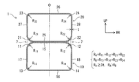
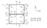
- FIG. 2 is a cross-sectional view (a cross-sectional view taken along the line AA in FIG. 1) of the underrun protector according to the embodiment. It is sectional drawing similar to FIG. 2 of the underrun protector which concerns on one modification. It is sectional drawing similar to FIG. 2 of the underrun protector which concerns on another modification.
- the arrow RR indicates the rear in the vehicle front-rear direction (vehicle length direction), and the arrow UP indicates the upper in the vehicle vertical direction.
- an underrun protector (rear underrun protector, RUP) provided at the rear of the vehicle is illustrated, but the underrun protector is provided at the front of the vehicle (front underrun protector).
- Run protector, FUP In the rear underrun protector, the front side in the vehicle front-rear direction is an attachment side, and the rear side in the vehicle front-rear direction is a collision side. In the front underrun protector, the rear side in the vehicle front-rear direction is an attachment side, and the front side in the vehicle front-rear direction is a collision side.
- the underrun protector 1 according to the present embodiment shown in FIG. 1 and the modification shown in FIGS. 3 and 4 extends in the vehicle width direction at the rear portion of the vehicle.
- a pair of side rails 2 and 2 extending substantially horizontally in the vehicle length direction are disposed in front of and above the underrun protector 1.
- a cross member 3 extending in the vehicle width direction is coupled between the rear end portions of the side rails 2 and 2.
- the underrun protector 1 is fixed to the side rails 2 and 2 via brackets 4.
- the bracket 4 extends rearward and downward from the side rails 2 and 2 and has a mounting surface 4a at the rear end thereof.
- the attachment surface 4a is a surface to which the underrun protector 1 is attached, and is formed in a planar shape extending in the vehicle width direction and the vertical direction, for example.
- the mounting surface 4a and the underrun protector 1 are fastened with bolts (not shown). Further, the front end portion of the bracket 4 is fastened to the side rail 2 with a plurality of bolts 5.
- the underrun protector 1 has a prismatic appearance and is arranged such that its longitudinal axis is horizontal.
- a cap 6 is attached to the end of the underrun protector 1 in the vehicle width direction.
- the underrun protector 1 is not limited to one having a longitudinal axis extending linearly, and may have a shape in which, for example, a longitudinal end is bent. Further, the cap 6 may be omitted.
- the underrun protector 1 includes a hollow lower pipe 10 and a hollow upper pipe 20 disposed above the lower pipe 10.
- the lower pipe 10 and the upper pipe 20 of the present embodiment are obtained by processing the same pipe member by roll molding, and each has a cross section (here, a cross section cut by a vertical plane extending in the vehicle length direction). Make a uniform shape.
- a case where the lower pipe 10 and the upper pipe 20 have the same shape will be described. That is, the lower pipe 10 and the upper pipe 20 shown here are obtained by performing the same processing on the same pipe member.
- each of the lower pipe 10 and the upper pipe 20 has a closed cross section whose cross section is substantially rectangular (four corners of the rectangle are curved, hereinafter referred to as a rectangle). It is a pipe.
- the cross sections of the pipes 10 and 20 are symmetrical with respect to a central axis O (an axis passing through an intermediate point between the front and rear ends of the pipes 10 and 20) extending in the vertical direction.
- the cross-sectional shape of the lower pipe 10 and the cross-sectional shape of the upper pipe 20 are vertically symmetrical with each other.
- the thickness (thickness) t of each part is uniform (substantially uniform) in the cross section.
- the lower pipe 10 has four surface portions 15 to 18 as portions corresponding to four sides of a rectangle formed by the cross section thereof.
- the four surface portions 15 to 18 are specifically the lower joint surface portion 15, the lower flat surface portion 16, the lower front surface portion 17, and the lower rear surface portion 18, and in the rectangle described above, the upper end side, the lower end side, and the front end, respectively. It corresponds to the edge and the rear edge.
- the surface portions 15 to 18 are all flat.
- the lower pipe 10 has four corner portions 11 to 14 as portions corresponding to four corners (corners) of a rectangle formed by the cross section thereof.
- the four corners 11 to 14 are a lower first corner 11, a lower second corner 12, a lower third corner 13, and a lower fourth corner 14, and the rectangular shape described above. These correspond to the upper and front corners, the upper and rear corners, the lower and front corners, and the lower and rear corners, respectively.
- Each of the corner portions 11 to 14 has a center of curvature and is formed in a curved surface shape.
- the four surface portions 15 to 18 and the four corner portions 11 to 14 form a smoothly continuous surface.
- the lower joint surface portion 15 and the lower flat surface portion 16 are extended in a horizontal plane along the vehicle width direction.
- the shorter direction (the direction perpendicular to the longitudinal direction) of the lower joint surface portion 15 and the lower flat surface portion 16 is shorter than the longitudinal direction (vehicle width direction) of the lower joint surface portion 15 and the lower flat surface portion 16. Also called hand direction.
- the short direction of the lower joint surface portion 15 and the lower flat surface portion 16 is the vehicle front-rear direction.
- the lower first corner portion 11 is a front end (one end) of the lower joint surface portion 15 in the short direction, and is curved forward and downward.
- the lower second corner portion 12 is a rear end (the other end) in the short direction of the lower joint surface portion 15 and is curved rearward and downward.
- the lower third corner portion 13 is a front end in the short direction of the lower flat surface portion 16, is curved forward and upward, and is substantially perpendicular to the lower first corner portion 11 and the lower joint surface portion 15. Opposite in direction.
- the lower fourth corner portion 14 is a rear end of the lower plane portion 16 in the short direction, is curved rearward and upward, and is an approximate shape of the lower second corner portion 12 and the lower joint surface portion 15. Opposite in the vertical direction.
- the lower front surface portion 17 extends between the lower end side of the lower first corner portion 11 and the upper end side of the lower third corner portion 13.
- the lower rear surface portion 18 extends between the lower end side of the lower second corner portion 12 and the upper end side of the lower fourth corner portion 14.
- the lower front surface portion 17 and the lower rear surface portion 18 both extend along the vehicle width direction and the vertical direction (that is, substantially perpendicular to the lower joint surface portion 15 and the lower flat surface portion 16), and mutually Opposite.
- the lower pipe 10 and the upper pipe 20 have the same shape, and the cross-sectional shapes are vertically symmetrical with each other.
- the upper pipe 20 has four face portions 25 to 28 and four corner portions 21 to 24.
- the four surface portions 25 to 28 are specifically the upper joint surface portion 25, the upper flat surface portion 26, the upper front surface portion 27, and the upper rear surface portion 28. , Corresponding to the front and rear edges.
- the four corners 21 to 24 are specifically the upper first corner 21, the upper second corner 22, the upper third corner 23, and the upper fourth corner 24. This corresponds to the lower and front corners, the lower and rear corners, the upper and front corners, and the upper and rear corners.
- the upper joint surface portion 25 and the upper planar portion 26 are extended in a horizontal plane along the vehicle width direction.
- the upper joint surface portion 25 abuts on the lower joint surface portion 15.
- the short side direction direction perpendicular to the longitudinal direction of the upper joint surface portion 25 and the upper flat surface portion 26 is also referred to as the short direction.
- the lateral direction of the upper joint surface portion 25 and the upper flat surface portion 26 is the vehicle front-rear direction.
- the upper first corner portion 21 is a front end (one end) of the upper joint surface portion 25 in the short direction, and is curved forward and upward.
- the upper second corner portion 22 is a rear end (the other end) in the short direction of the upper joint surface portion 25 and is curved rearward and upward.
- the upper third corner portion 23 is a front end in the short direction of the upper plane portion 26, curves forward and downward, and faces the upper first corner portion 21 and the upper joint surface portion 25 in a substantially vertical direction.
- the upper fourth corner 24 is the rear end of the upper flat portion 26 in the short direction, curves backward and downward, and faces the upper second corner 22 and the upper joint surface 25 in a substantially vertical direction. To do.
- the upper front surface portion 27 extends between the upper end side of the upper first corner portion 21 and the lower end side of the upper third corner portion 23.
- the upper rear surface portion 28 extends between the upper end side of the upper second corner portion 22 and the lower end side of the upper fourth corner portion 24.
- the upper front surface portion 27 and the upper rear surface portion 28 both extend along the vehicle width direction and the vertical direction (that is, substantially perpendicular to the upper joint surface portion 25 and the upper flat surface portion 26) and face each other. .
- the lower front surface portion 17 and the upper front surface portion 27 are portions that form the front surface of the underrun protector 1.
- the lower front surface portion 17 and the upper front surface portion 27 are disposed on the same plane.
- the lower rear surface portion 18 and the upper rear surface portion 28 are portions forming the rear surface of the under-run protector 1.
- the lower rear surface portion 18 and the upper rear surface portion 28 are arranged on the same plane.
- the lower pipe 10 and the upper pipe 20 are joined by welding the front end sides and the rear end sides of the lower joint surface portion 15 and the upper joint surface portion 25, respectively. That is, the lower first corner 11 and the upper first corner 21 are joined by welding, and the lower second corner 12 and the upper second corner 22 are joined by welding.
- the amount of filler material used at this time (hereinafter also referred to as welding amount) is in accordance with the thickness t of the pipes 10 and 20. Specifically, the welding amount increases as the wall thickness t of the pipes 10 and 20 increases.
- the radius of curvature R of the four corners 11 , 12 , 21 , and 22 to be welded (hereinafter referred to as R 11 , R 12 , R 21 , and R 22 , respectively, with reference to the corresponding corners) will be described.
- any of the four curvature radii R 11 , R 12 , R 21 , R 22 is used to secure a space for the filler material between the two corners welded to each other.
- the pipes 10 and 20 are set to be at least three times the wall thickness t (R 11 ⁇ 3t, R 12 ⁇ 3t, R 21 ⁇ 3t, and R 22 ⁇ 3t).
- the radii of curvature R of the other four corners 13 , 14 , 23 , and 24 (hereinafter referred to as R13, R14, R23, and R24, respectively, with the corresponding corners added) will be described.
- the four curvature radii R 13 , R 14 , R 23 , R 24 are all the curvature radii R 11 , R 12 , R. 21, is smaller than R 22 (R 13 ⁇ R A and,, R 14 ⁇ R A and,, R 23 ⁇ R A and,, R 24 ⁇ R A) .
- the radii of curvature R 13 , R 14 , R 23 , R 24 are preferably about twice as large as the wall thickness t.
- the radii of curvature R 11 and R 12 are both set larger than the radii of curvature R 13 and R 14 , but the lower pipe 10 has a radius of curvature R 11.
- R 12 may be set to be larger than at least one of the curvature radii R 13 , R 14 .
- FIG. 3 shows only the latter of the lower first corner 11 and the upper first corner 21 and only the former of the lower second corner 12 and the upper second corner 22 in the underrun protector 1.
- FIG. 4 shows only the former of the lower first corner 11 and the upper first corner 21 and only the former of the lower second corner 12 and the upper second corner 22 in the underrun protector 1.
- Each of which has a radius of curvature R 12 that is three or more times the wall thickness t (R 11 ⁇ 3t, R 21 ⁇ 3t, R 12 ⁇ 3t, and R 21 ⁇ 3t). ing.
- the lower pipe 10 and the upper pipe 20 have different shapes.
- the two pipes 10 and 20 are formed by roll-forming the same pipe member. In other words, when the two pipes 10 and 20 are roll-formed, different processes are applied to the same material. In this case, the two pipes 10 and 20 after roll forming have the same outer diameter and thickness.
- the thickness t of each part does not need to be uniform in a cross section. If the thicknesses t of the pipes 10 and 20 are not uniform, the radius of curvature may be set as described above based on the minimum value of the thickness t of the pipes 10 and 20.
- the lower pipe 10 only needs to include at least the lower joint surface portion 15 and the lower first corner portion 11 and the lower second corner portion 12 continuous to the lower joint surface portion 15, and the shape of the cross section is rectangular. It does not have to be.
- the cross section of the lower pipe 10 may be, for example, a semicircular closed cross section whose diameter is the lower joint surface portion 15. The same applies to the upper pipe 20, and the shape of the cross section of the upper pipe 20 is not limited to the rectangle.
- the pipes 10 and 20 may be formed by different molding methods. That is, the material and forming method of the pipes 10 and 20 are not limited to those exemplified above.
- the underrun protector 1 may be formed by stacking three or more pipes in the vertical direction. For example, another pipe may be disposed and welded below the lower pipe 10 or above the upper pipe 20.
- the underrun protector 1 may have a space for the welded portion 7 only on either the attachment side or the collision side.
- the lower first corner portion 11 and the upper first corner portion 21 of the under-run protector 1 are welded to each other at a portion other than a mounting portion to the bracket 4 (portion facing the mounting surface 4a). It is also conceivable that protrusion of the welded portion 7 to the front side (attachment side) is allowed. In such a case, the space of the welded portion 7 may be ensured only on the collision side among the attachment side and the collision side of the underrun protector 1.
- the radius of curvature radius R 22 of R 12 and upper second corner portion 22) may be the same value as the previous R B.
- the radius of curvature R 12 of the lower second corner 12 (or the radius of curvature R 21 of the upper first corner portion 21) the same value (meat and the aforementioned R B Less than three times the thickness t).
- the curvature radius R 11 of the lower first corner 11 (or the curvature radius R 12 of the lower second corner 12 ) is set to be less than three times the wall thickness t. Also good.
- Each surface such as the lower front surface portion 17, the lower rear surface portion 18, the upper front surface portion 27, the upper rear surface portion 28, the lower flat surface portion 16, and the upper flat surface portion 26 is not limited to a flat shape, but a curved surface shape or the like. It may be.
- the underrun protector 1 is not limited to the configuration in which the lower pipe 10 and the upper pipe 20 are arranged in the vehicle vertical direction, and for example, the lower pipe 10 and the upper pipe 20 are arranged in the vehicle front-rear direction. (The under-run protector 1 shown in FIGS. 2 to 4 is rotated by 90 °). In this case, the lower plane portion 16 (or the upper plane portion 26) in FIGS.
- the upper plane portion 26 (or the lower plane portion 16) is disposed on the collision side, and the lower front surface Portion 17 and upper front surface portion 27 (or lower rear surface portion 18 and upper rear surface portion 28) are arranged on the upper side in the vehicle vertical direction, and lower rear surface portion 18 and upper rear surface portion 28 (or lower front surface portion 17 and upper front surface portion). 27) is arranged on the lower side in the vehicle vertical direction.
- the underrun protector 1 can be easily used as a step by preventing the welded portion 7 from protruding or excessively protruding from the upper surface of the underrun protector 1 in the vehicle vertical direction.
- the welded portion starts from the lower surface of the under-run protector 1 in the vertical direction of the vehicle.
- R 11 and R 21 (or R 12 and R 22 ) in FIG. 2 are set to the same value as R B , or R 12 (or R 21 ) in FIG. May be the same value as R B (less than three times the wall thickness t), or R 11 (or R 12 ) in FIG. 4 may be less than three times the wall thickness t.
- the underrun protector 1 may be one in which a plurality of pipes are arranged side by side in any of the vehicle vertical direction and the vehicle front-rear direction.
- other pipes may be arranged in the vehicle longitudinal direction and welded to the pipes 10 and 20 arranged in the vehicle vertical direction.
- the space for the welded portion can be secured by devising the radius of curvature at the corner of the pipe as described above.
- the radii of curvature of the corners 11 to 14 and 21 to 24 are constant (one radii of curvature exists in one corner).
- the present invention is not limited to this, and the radii of curvature of the corners 11 to 14 and 21 to 24 may not be constant (a plurality of radii of curvature may exist at one corner).
- the above-mentioned setting of the curvature radius (comparison with other curvature radii and thickness t Comparison).
- the larger value (maximum value) of the two radii of curvature is used as a reference, and this larger value Is set to be equal to or greater than three times the wall thickness t, the smaller value may be set to less than three times the wall thickness t. Even in such a case, the space of the welded portion 7 is secured in the underrun protector 1 as described above.
- the lower pipe 10 and the upper pipe 20 may include a member such as a reinforcing member in the hollow portion.
- the hollow first member and the hollow second member described in the present specification and claims need only have some space in the cross section in the short direction of the first member and the second member.
- those including a member such as a reinforcing member in the cross section are also included.
- the curvature radii R 11 and R 12 of the lower pipe 10 are less than three times the wall thickness t if at least one of them is larger than at least one of the curvature radii R 13 and R 14. There may be. Further, the curvature radii R 11 and R 12 of the lower pipe 10 may be smaller than the curvature radii R 13 and R 14 as long as at least one of them is at least three times the wall thickness t. The same applies to the upper pipe 20, and the curvature radii R 21 and R 22 are less than three times the wall thickness t if at least one of them is larger than at least one of the curvature radii R 23 and R 24. It may be.
- the curvature radii R 21 and R 22 of the upper pipe 20 may be smaller than the curvature radii R 23 and R 24 as long as at least one of them is at least three times the wall thickness t. In any case, according to the underrun protector 1, a space for the welded portion 7 is ensured.
- the “substantially vertical direction” described in the present specification and claims means that it may not be strictly vertical (it may include some errors that may occur in processing).
- At least one of the curvature radii R 11 and R 12 is at least one of the curvature radii R 13 and R 14 (or R 23 or R 24 ). It is set larger than one. Therefore, as compared with the case where the radius of curvature of all the corner portions as in the conventional underrun protector is set to a size of said R B equivalent, the first lower corner 11 and the upper first corner portion 21 And a space provided in at least one of the lower second corner 12 and the upper second corner 22 can be increased. Therefore, the protrusion of the welded portion 7 can be prevented or excessive protrusion can be prevented (protrusion exceeding an allowable range can be prevented).
- the curvature radii R 11 and R 12 are set larger than any of the curvature radii R 13 and R 14 (or R 23 and R 24 ). Therefore, for example, as shown by a virtual line in FIG. 2, the welded portion 7 can be accommodated in the space, and the welded portion 7 can be prevented from projecting or excessively projecting from the under-run protector 1. it can.
- At least one of the radii of curvature R 11 , R 12 is at least three times the wall thickness t of the pipe 10 (or pipe 20). Is set. Thereby, the space for welding is ensured.
- the larger the radius of curvature R 11 the larger the space between the lower first corner 11 and the upper first corner 21. That is, by setting the curvature radius R 11 as described above, a space corresponding to the wall thickness t of the pipe 10 is secured between the lower first corner 11 and the upper first corner 21. . Therefore, as described above, the protrusion or excessive protrusion of the welded portion 7 can be prevented.
- the lower third corner 13 and the lower fourth corner 14 (or the upper third corner 23 and the upper fourth corner 24) are provided, and the radii of curvature R 11 , R 12 (or R 21 , When at least one of R 22 ) is larger than at least one of the curvature radii R 13 and R 14 (or R 23 and R 24 ), the rigidity of the underrun protector 1 can be improved.
- the radius of curvature R 11 , R 12 (or R 21 , R 22 ) is set to a value that is at least three times the wall thickness t of the pipe 10 (or pipe 20). Thereby, the space for welding is ensured. For example, by setting the curvature radii R 11 and R 12 as described above, the lower first corner 11 and the upper first corner 21 and the lower first corner 12 and the upper first corner 21 are set. A space corresponding to the wall thickness t of the pipe 10 is secured between the corner 22. Therefore, the protrusion of the welding part 7 or an excessive protrusion can be prevented.
- the pipe 10 (or the pipe 20) is a rectangular pipe having a rectangular closed cross section.
- the pipe 10 and the pipe 20 are rectangular pipes having a rectangular closed cross section.
- the lower front surface portion 17 and the upper front surface portion 27 are arranged on the same plane.
- the lower rear surface portion 18 and the upper rear surface portion 28 are disposed on the same plane. Therefore, it is possible to suppress the generation of a step between the lower front surface portion 17 and the upper front surface portion 27 and the generation of a step between the lower rear surface portion 18 and the upper rear surface portion 28.
- the lower pipe 10 and the upper pipe 20 are arranged side by side in the vehicle vertical direction. Thereby, the protrusion or the excessive protrusion of the welding part 7 can be prevented in the collision side or attachment side of the underrun protector 1. Therefore, the underrun protector 1 can be easily attached to the attachment surface 4 a of the bracket 4. Alternatively, it is possible to more appropriately suppress the intrusion of another vehicle.
- the lower pipe 10 and the upper pipe 20 have the same shape. In this case, the same member can be applied to the two pipes 10 and 20. Therefore, the types of members constituting the underrun protector 1 can be reduced, and the members can be easily managed. Moreover, since it is possible to form the two pipes 10 and 20 with the same shaping
- the lower pipe 10 and the upper pipe 20 are formed by roll forming the same pipe member. That is, when the lower pipe 10 and the upper pipe 20 are roll-formed, the same material is used. Therefore, compared with the case where a different material is applied to the two pipes 10 and 20, the kind of material can be reduced. Therefore, management of the member before roll forming can be facilitated.
- the lower pipe 10 corresponds to one of the first member and the second member recited in the claims
- the upper pipe 20 It corresponds to the other. That is, when the lower pipe 10 corresponds to the first member described in the claims, the upper pipe 20 corresponds to the second member described in the claims, and the lower joint surface portion 15 corresponds to the second member.
- the lower first corner 11, the lower second corner 12, the lower third corner 13, and the lower fourth corner 14 correspond to the surface portion described in the range. It corresponds to the corner, the second corner, the third corner, and the fourth corner, respectively.
- the upper pipe 20 corresponds to the first member described in the claims, and the upper joint surface portion 25 described in the claims.
- the upper first corner 21, the upper second corner 22, the upper third corner 23, and the upper fourth corner 24 are the first corner and the second corner described in the claims. , Corresponding to the third corner and the fourth corner, respectively.
- Lower pipe (first member, second member) 11 Lower first corner (first corner) 12 Lower second corner (second corner) 13 Lower third corner (third corner) 14 Lower fourth corner (fourth corner) 15 Lower joint surface (surface) 16 Lower flat surface portion 17 Lower front surface portion 18 Lower rear surface portion 20 Upper pipe (first member, second member) 21 Upper first corner (first corner) 22 Upper second corner (second corner) 23 Upper third corner (third corner) 24 Upper fourth corner (fourth corner) 25 Upper joint surface (surface) 26 Upper Plane Part 27 Upper Front Part 28 Upper Rear Part
Landscapes
- Engineering & Computer Science (AREA)
- Mechanical Engineering (AREA)
- Details Of Indoor Wiring (AREA)
Abstract
【課題】アンダーランプロテクタに関し、溶接部の突出を防止する。 【解決手段】中空の下側パイプ10と、下側パイプ10と溶接で接合される中空の上側パイプ20とを設ける。下側パイプ10には、上側パイプ20と当接される下側接合面部15と、下側接合面部15の短手方向の両端である下側第一隅部11および下側第二隅部12と、を設ける。そして、下側第一隅部11及び下側第二隅部12の少なくとも何れか一方の曲率半径R11,R12を、下側パイプ10の肉厚tの三倍以上とする。
Description
本発明は、車両の前部または後部に設けられ、他車両の潜り込みを抑制するアンダーランプロテクタに関する。
トラックなどの車両には、他車両が潜り込むことを防止するためにアンダーランプロテクタが設けられる。一般に、アンダーランプロテクタは、車両の前部または後部において車幅方向に延設され、ブラケットを介して車体フレームに固定される。
従来、アンダーランプロテクタの一つとして、車幅方向に延びる複数のパイプ部材が車両上下方向に重ねられてなるものが知られる(例えば特許文献1参照)。このようなアンダーランプロテクタでは、下側のパイプ部材の上面部に上側のパイプ部材の下面部が重ねられ、それぞれ溶接によって接合される。
また、複数のパイプ部材を車両前後方向に並べ、それぞれ溶接によって接合するアンダーランプロテクタなども考えられる。
従来、アンダーランプロテクタの一つとして、車幅方向に延びる複数のパイプ部材が車両上下方向に重ねられてなるものが知られる(例えば特許文献1参照)。このようなアンダーランプロテクタでは、下側のパイプ部材の上面部に上側のパイプ部材の下面部が重ねられ、それぞれ溶接によって接合される。
また、複数のパイプ部材を車両前後方向に並べ、それぞれ溶接によって接合するアンダーランプロテクタなども考えられる。
しかしながら、アンダーランプロテクタにおいて前記のように車両上下方向に重ねられたパイプ部材が溶接される場合、溶接された部分(以下、溶接部という)の肉厚が大きくなり、溶接部が車両前後方向の車両前側または車両後側に突き出る可能性がある。アンダーランプロテクタの車両前側または車両後側は、車両への取付側(以下、単に取付側という)または他車両が衝突する可能性がある側(以下、単に衝突側という)である。よって、溶接部の突出(もしくは許容範囲以上の突出)は望ましくない。
また、車両前後方向に並べられたパイプ部材が溶接される場合も、溶接部の肉厚が大きくなり、溶接部が車両上下方向の車両上側または車両下側に突き出る可能性がある。アンダーランプロテクタの車両上側はステップとして兼用される場合があり、車両下側はアンダーランプロテクタを車両に取り付ける際の基準となる(国によっては、法規でアンダーランプロテクタの地上に対する下端位置について規定がある)。よって、この場合も前記のような溶接部の突出(もしくは許容範囲以上の突出)は望ましくない。
尚、場合によっては、アンダーランプロテクタの車両前側または車両後側の何れか一方や、車両上下方向の車両上側または車両下側の何れか一方の突出は許容されることもあり得る。
尚、場合によっては、アンダーランプロテクタの車両前側または車両後側の何れか一方や、車両上下方向の車両上側または車両下側の何れか一方の突出は許容されることもあり得る。
本件は、前記のような課題に鑑み創案されたものであり、アンダーランプロテクタに関し、溶接部の突出を防止するまたは過度の突出を防止することを目的とする。
本発明は、前述の課題の少なくとも一部を解決するためになされたものであり、以下の態様または適用例として実現することができる。
(1)一適用例に係るアンダーランプロテクタは、中空の第一部材と、前記第一部材と溶接で接合される中空の第二部材と、を備えるアンダーランプロテクタであって、前記第一部材は、前記第二部材と当接される面部と、前記面部の短手方向の一端である第一隅部と、前記面部の短手方向の他端である第二隅部と、前記第一隅部と前記面部の略垂直方向で対向する第三隅部と、前記第二隅部と前記面部の略垂直方向で対向する第四隅部と、を有し、前記第一隅部及び前記第二隅部の少なくとも何れか一方の曲率半径が、前記第三隅部及び前記第四隅部の少なくとも何れか一方の曲率半径よりも大きい。
(1)一適用例に係るアンダーランプロテクタは、中空の第一部材と、前記第一部材と溶接で接合される中空の第二部材と、を備えるアンダーランプロテクタであって、前記第一部材は、前記第二部材と当接される面部と、前記面部の短手方向の一端である第一隅部と、前記面部の短手方向の他端である第二隅部と、前記第一隅部と前記面部の略垂直方向で対向する第三隅部と、前記第二隅部と前記面部の略垂直方向で対向する第四隅部と、を有し、前記第一隅部及び前記第二隅部の少なくとも何れか一方の曲率半径が、前記第三隅部及び前記第四隅部の少なくとも何れか一方の曲率半径よりも大きい。
(2)一適用例に係るアンダーランプロテクタにおいて、前記第一隅部及び前記第二隅部の曲率半径は、前記第三隅部及び前記第四隅部の何れの曲率半径よりも大きくてもよい。
(3)他の一適用例に係るアンダーランプロテクタは、中空の第一部材と、前記第一部材と溶接で接合される中空の第二部材と、を備えるアンダーランプロテクタであって、前記第一部材は、前記第二部材と当接される面部と、前記面部の短手方向の一端である第一隅部と、前記面部の短手方向の他端である第二隅部と、を有し、前記第一隅部及び前記第二隅部の少なくとも何れか一方の曲率半径が、前記第一部材の肉厚の三倍以上である。
(3)他の一適用例に係るアンダーランプロテクタは、中空の第一部材と、前記第一部材と溶接で接合される中空の第二部材と、を備えるアンダーランプロテクタであって、前記第一部材は、前記第二部材と当接される面部と、前記面部の短手方向の一端である第一隅部と、前記面部の短手方向の他端である第二隅部と、を有し、前記第一隅部及び前記第二隅部の少なくとも何れか一方の曲率半径が、前記第一部材の肉厚の三倍以上である。
(4)一適用例に係るアンダーランプロテクタにおいて、前記第一部材は、前記第一隅部と前記面部の略垂直方向で対向する第三隅部と、前記第二隅部と前記面部の略垂直方向で対向する第四隅部と、をさらに有し、前記第一隅部及び前記第二隅部の少なくとも何れか一方の曲率半径が、前記第三隅部及び前記第四隅部の少なくとも何れか一方の曲率半径よりも大きくてもよい。
(5)一適用例に係るアンダーランプロテクタにおいて、前記第一隅部及び前記第二隅部の曲率半径は、前記肉厚の三倍以上であってもよい。
(6)一適用例に係るアンダーランプロテクタにおいて、前記第一部材は、横断面が略矩形状に形成されてもよい。
(7)一適用例に係るアンダーランプロテクタにおいて、前記第二部材は、横断面が略矩形状に形成されてもよい。
(6)一適用例に係るアンダーランプロテクタにおいて、前記第一部材は、横断面が略矩形状に形成されてもよい。
(7)一適用例に係るアンダーランプロテクタにおいて、前記第二部材は、横断面が略矩形状に形成されてもよい。
(8)一適用例に係るアンダーランプロテクタにおいて、前記第一部材は、前記面部と略垂直な二つの面が、前記第二部材の対向する二つの面とそれぞれ同一の平面上に配置されてもよい。
(9)一適用例に係るアンダーランプロテクタにおいて、前記第一部材及び前記第二部材は、車両上下方向に並べて配置されてもよい。
(9)一適用例に係るアンダーランプロテクタにおいて、前記第一部材及び前記第二部材は、車両上下方向に並べて配置されてもよい。
(10)一適用例に係るアンダーランプロテクタにおいて、前記第一部材及び前記第二部材は、車両前後方向に並べて配置されてもよい。
(11)一適用例に係るアンダーランプロテクタにおいて、前記第一部材及び前記第二部材が、同一の形状であってもよい。
(12)一適用例に係るアンダーランプロテクタにおいて、前記第一部材及び前記第二部材が、同一の部材をロール成形することによって形成されてもよい。
(11)一適用例に係るアンダーランプロテクタにおいて、前記第一部材及び前記第二部材が、同一の形状であってもよい。
(12)一適用例に係るアンダーランプロテクタにおいて、前記第一部材及び前記第二部材が、同一の部材をロール成形することによって形成されてもよい。
複数の中空部材を溶接し構成されるアンダーランプロテクタにおいて、溶接部が部材から突出することを防止する、または、過度に突出することを防止する(許容範囲を超える突出を防止する)ことができる。
図面を参照して、一実施形態及び変形例としてのアンダーランプロテクタについて説明する。図面では、矢印RRが車両前後方向(車長方向)における後方を示し、矢印UPが車両上下方向における上方を示す。なお、本実施形態及び変形例では、車両の後部に設けられたアンダーランプロテクタ(リヤアンダーランプロテクタ,RUP)を例示するが、本アンダーランプロテクタは、車両の前部に設けられるもの(フロントアンダーランプロテクタ,FUP)であってもよい。リヤアンダーランプロテクタでは、車両前後方向の前側が取付側であり、車両前後方向の後側が衝突側である。また、フロントアンダーランプロテクタでは、車両前後方向の後側が取付側であり、車両前後方向の前側が衝突側である。
[1.構成]
図1に示す本実施形態及び図3,図4に示す変形例に係るアンダーランプロテクタ1は、車両の後部において車幅方向に延在する。アンダーランプロテクタ1の前方かつ上方には、車長方向に略水平に延びる一対のサイドレール2,2が配設される。また、サイドレール2,2の後端部の間には、車幅方向に延びるクロスメンバ3が結合される。
図1に示す本実施形態及び図3,図4に示す変形例に係るアンダーランプロテクタ1は、車両の後部において車幅方向に延在する。アンダーランプロテクタ1の前方かつ上方には、車長方向に略水平に延びる一対のサイドレール2,2が配設される。また、サイドレール2,2の後端部の間には、車幅方向に延びるクロスメンバ3が結合される。
アンダーランプロテクタ1は、サイドレール2,2のそれぞれに対し、ブラケット4を介して固定される。ブラケット4は、サイドレール2,2から後方かつ下方に向かって延び、その後端に取付面4aを有する。取付面4aは、アンダーランプロテクタ1が取り付けられる面であり、例えば車幅方向かつ上下方向に延びる平面状に形成される。尚、取付面4aとアンダーランプロテクタ1とは、図示しないボルトで締結されている。また、ブラケット4の前端部は、サイドレール2に対して複数のボルト5で締結される。
アンダーランプロテクタ1は、外観形状が角柱状であり、その長手方向の軸心が水平となるように配置される。また、アンダーランプロテクタ1の車幅方向における端部には、キャップ6が取り付けられる。
なお、アンダーランプロテクタ1は、その長手方向の軸心が直線上に延びるものに限らず、例えば長手方向の端部が屈曲された形状であってもよい。また、キャップ6は省略されてもよい。
なお、アンダーランプロテクタ1は、その長手方向の軸心が直線上に延びるものに限らず、例えば長手方向の端部が屈曲された形状であってもよい。また、キャップ6は省略されてもよい。
以下、アンダーランプロテクタ1の構成について詳述する。アンダーランプロテクタ1は、中空の下側パイプ10と、下側パイプ10の上方に配置された中空の上側パイプ20とを備える。本実施形態の下側パイプ10と上側パイプ20とは、同一のパイプ部材を何れもロール成形により加工したものであり、それぞれ横断面(ここでは車長方向に延びる鉛直面で切った断面)が一様な形状をなす。本実施形態では、下側パイプ10と上側パイプ20とが同一の形状である場合について説明する。すなわち、ここで示す下側パイプ10と上側パイプ20とは、同一のパイプ部材に対して同一の加工が施されたものである。
図2に示すように、下側パイプ10及び上側パイプ20は、何れも横断面が略矩形(矩形の四つの角を曲線状にしたもの、以下矩形と記す。)状の閉断面をなす角パイプである。各パイプ10,20における横断面は、上下方向に延びる中心軸O(各パイプ10,20の前端と後端との中間点を通る軸線)について対称な形状とされる。また、下側パイプ10の横断面形状と上側パイプ20の横断面形状とは、互いに上下対称である。下側パイプ10及び上側パイプ20は、各部の厚み(肉厚)tが横断面において一様(略均一)とされる。
ここで、下側パイプ10に着目して説明する。下側パイプ10は、その横断面がなす矩形の四つの辺にそれぞれ相当する部位として、四つの面部15~18を有する。四つの面部15~18は、具体的には下側接合面部15,下側平面部16,下側前面部17,下側後面部18であり、前記の矩形ではそれぞれ上端辺,下端辺,前端辺,後端辺に相当する。面部15~18は、何れも平板状である。
また、下側パイプ10は、その横断面がなす矩形の四つの角(隅)に相当する部位として、四つの隅部11~14を有する。四つの隅部11~14は、具体的には下側第一隅部11,下側第二隅部12,下側第三隅部13,下側第四隅部14であり、前記の矩形ではそれぞれ上側かつ前側の角,上側かつ後ろ側の角,下側かつ前側の角,下側かつ後ろ側の角に相当する。隅部11~14は、何れも曲率中心を有し、曲面状に形成されている。下側パイプ10において、四つの面部15~18と四つの隅部11~14とは、滑らかに連続した面をなす。
下側接合面部15及び下側平面部16は、車幅方向に沿って水平面状に延設される。以下、下側接合面部15及び下側平面部16の長手方向(車幅方向)に対し、下側接合面部15及び下側平面部16の短い側の方向(長手方向と直交する方向)を短手方向ともいう。本実施形態では、下側接合面部15及び下側平面部16の短手方向は車両前後方向である。
下側第一隅部11は、下側接合面部15の短手方向の前端(一端)であり、前方かつ下方に向かって湾曲する。また、下側第二隅部12は、下側接合面部15の短手方向の後端(他端)であり、後方かつ下方に向かって湾曲する。一方、下側第三隅部13は、下側平面部16の短手方向の前端であり、前方かつ上方に向かって湾曲し、下側第一隅部11と下側接合面部15の略垂直方向で対向する。また、下側第四隅部14は、下側平面部16の短手方向の後端であり、後方かつ上方に向かって湾曲し、下側第二隅部12と下側接合面部15の略垂直方向で対向する。
下側前面部17は、下側第一隅部11の下端辺と下側第三隅部13の上端辺との間に延設される。一方、下側後面部18は、下側第二隅部12の下端辺と下側第四隅部14の上端辺との間に延設される。本実施形態では、下側前面部17及び下側後面部18が、何れも車幅方向かつ上下方向に沿って(すなわち下側接合面部15及び下側平面部16と略垂直に)延び、互いに対向している。
次に、上側パイプ20について説明する。前記のとおり、本実施形態では下側パイプ10と上側パイプ20とが同一の形状であり、横断面形状が互いに上下対称な形状をなす。
上側パイプ20は、四つの面部25~28及び四つの隅部21~24を有する。四つの面部25~28は、具体的には上側接合面部25,上側平面部26,上側前面部27,上側後面部28であり、上側パイプ20の横断面がなす矩形ではそれぞれ下端辺,上端辺,前端辺,後端辺に相当する部位である。また、四つの隅部21~24は、具体的には上側第一隅部21,上側第二隅部22,上側第三隅部23,上側第四隅部24であり、前記の矩形ではそれぞれ下側かつ前側の角,下側かつ後ろ側の角,上側かつ前側の角,上側かつ後ろ側の角に相当する。
上側接合面部25及び上側平面部26は、車幅方向に沿って水平面状に延設される。上側接合面部25は、下側接合面部15に当接する。以下、上側接合面部25及び上側平面部26の長手方向(車幅方向)に対し、上側接合面部25及び上側平面部26の短い側の方向(長手方向と直交する方向)を短手方向ともいう。本実施形態では、上側接合面部25及び上側平面部26の短手方向は車両前後方向である。
上側第一隅部21は、上側接合面部25の短手方向の前端(一端)であり、前方かつ上方に向かって湾曲する。また、上側第二隅部22は、上側接合面部25の短手方向の後端(他端)であり、後方かつ上方に向かって湾曲する。一方、上側第三隅部23は、上側平面部26の短手方向の前端であり、前方かつ下方に向かって湾曲し、上側第一隅部21と上側接合面部25の略垂直方向で対向する。また、上側第四隅部24は、上側平面部26の短手方向の後端であり、後方かつ下方に向かって湾曲し、上側第二隅部22と上側接合面部25の略垂直方向で対向する。
上側前面部27は、上側第一隅部21の上端辺と上側第三隅部23の下端辺との間に延設される。一方、上側後面部28は、上側第二隅部22の上端辺と上側第四隅部24の下端辺との間に延設される。本実施形態では、上側前面部27及び上側後面部28が、何れも車幅方向かつ上下方向に沿って(すなわち上側接合面部25及び上側平面部26と略垂直に)延び、互いに対向している。
下側前面部17及び上側前面部27は、アンダーランプロテクタ1の前面をなす部位である。下側前面部17と上側前面部27とは、互いに同一の平面上に配置される。また、下側後面部18及び上側後面部28は、アンダーランプロテクタ1の後面をなす部位である。下側後面部18と上側後面部28とは、互いに同一の平面上に配置される。
下側パイプ10と上側パイプ20とは、下側接合面部15及び上側接合面部25の各前端辺と各後端辺とがそれぞれ溶接されることによって結合される。すなわち、下側第一隅部11と上側第一隅部21とが溶接により接合され、下側第二隅部12と上側第二隅部22とが溶接により接合される。このとき使用される溶加材の量(以下、溶接量ともいう)は、パイプ10,20の肉厚tに応じたものとなる。具体的には、パイプ10,20の肉厚tが大きいほど、溶接量も増加する。
ここで、溶接される四つの隅部11,12,21,22の曲率半径R(以下、対応する隅部の符号を添えてそれぞれR11,R12,R21,R22とする)について説明する。本実施形態のアンダーランプロテクタ1では、互いに溶接される二つの隅部の間に溶加材のためのスペースを確保すべく、四つの曲率半径R11,R12,R21,R22が何れもパイプ10,20における肉厚tの三倍以上の大きさに設定されている(R11≧3t、かつ、R12≧3t、かつ、R21≧3t、かつ、R22≧3t)。
なお、本実施形態では、四つの曲率半径R11,R12,R21,R22が互いに等しい大きさ(RA)である(RA=R11=R12=R21=R22)場合を例示するが、曲率半径R11,R12,R21,R22は互いに異なる大きさであってもよい。また、下側第一隅部11と上側第一隅部21との何れか一方は、肉厚tの三倍よりも小さい曲率半径を具備してもよい(R11<3t、または、R21<3t)。また、下側第二隅部12と上側第二隅部22との何れか一方は、肉厚tの三倍よりも小さい曲率半径を具備してもよい(R12<3t、または、R22<3t)。すなわち、互いに溶接される二つの隅部のうち、少なくとも一方の曲率半径が肉厚tの三倍以上であれば、両者の間に溶加材のためのスペースが確保される。
次に、他の四つの隅部13,14,23,24の曲率半径R(以下、対応する隅部の符号を添えてそれぞれR13,R14,R23,R24とする)について説明する。本実施形態のアンダーランプロテクタ1では、中心軸Oに関する断面二次モーメントを確保すべく、四つの曲率半径R13,R14,R23,R24が何れも曲率半径R11,R12,R21,R22よりも小さく設定されている(R13<RA、かつ、R14<RA、かつ、R23<RA、かつ、R24<RA)。
なお、本実施形態では、四つの曲率半径R13,R14,R23,R24が互いに等しい大きさ(RB)である(RB=R13=R14=R23=R24)場合を例示するが、曲率半径R13,R14,R23,R24は互いに異なる大きさであってもよい。
また、四つの曲率半径R13,R14,R23,R24は、パイプ10,20における肉厚tの少なくとも1.5倍の大きさとされる(R13≧1.5t、かつ、R14≧1.5t、かつ、R23≧1.5t、かつ、R24≧1.5t)。これは、曲率半径R13,R14,R23,R24が肉厚tの1.5倍よりも小さく設定されると、パイプ10,20の加工性(成形のし易さ)が確保され難いためである。曲率半径R13,R14,R23,R24は、好ましくは肉厚tの2倍程度の大きさとされる。
また、四つの曲率半径R13,R14,R23,R24は、パイプ10,20における肉厚tの少なくとも1.5倍の大きさとされる(R13≧1.5t、かつ、R14≧1.5t、かつ、R23≧1.5t、かつ、R24≧1.5t)。これは、曲率半径R13,R14,R23,R24が肉厚tの1.5倍よりも小さく設定されると、パイプ10,20の加工性(成形のし易さ)が確保され難いためである。曲率半径R13,R14,R23,R24は、好ましくは肉厚tの2倍程度の大きさとされる。
なお、本実施形態の下側パイプ10では、曲率半径R11,R12が何れも曲率半径R13,R14の何れよりも大きく設定されているが、下側パイプ10は、曲率半径R11,R12の少なくとも何れか一方が、曲率半径R13,R14の少なくとも何れか一方よりも大きく設定されればよい。上側パイプ20についても同様であり、曲率半径R21,R22の少なくとも何れか一方が、曲率半径R23,R24の少なくとも何れか一方よりも大きく設定されればよい。
[2.変形例]
前記の実施形態に関わらず、それらの趣旨を逸脱しない範囲で種々変形して実施することができる。前記の実施形態の各構成は、必要に応じて取捨選択することができ、あるいは適宜組み合わせてもよい。
前記の実施形態で示したアンダーランプロテクタ1の断面形状は一例である。アンダーランプロテクタ1は、その横断面が例えば図3及び図4に示すような形状をなすものであってもよい。
前記の実施形態に関わらず、それらの趣旨を逸脱しない範囲で種々変形して実施することができる。前記の実施形態の各構成は、必要に応じて取捨選択することができ、あるいは適宜組み合わせてもよい。
前記の実施形態で示したアンダーランプロテクタ1の断面形状は一例である。アンダーランプロテクタ1は、その横断面が例えば図3及び図4に示すような形状をなすものであってもよい。
なお、図3及び図4に例示するものは、アンダーランプロテクタ1において、互いに溶接される二つの隅部のうちの一方のみが、パイプ10,20における最小肉厚tの三倍以上とされた曲率半径を具備する場合である。ここでは、前記の実施形態で説明した各要素に対応する要素に同一の符号を付し、前記の実施形態のものと同様の構成については説明を省略する。
図3は、アンダーランプロテクタ1において、下側第一隅部11及び上側第一隅部21のうちの後者のみと、下側第二隅部12及び上側第二隅部22のうちの前者のみとが、肉厚tの三倍以上の曲率半径R21,R12をそれぞれ具備する(R21≧3t、かつ、R11<3t、かつ、R12≧3t、かつ、R21<3t)場合を例示している。
なお、二つの曲率半径R12,R21は、互いに等しい大きさとされる(RA=R12=R21)。また、他の二つの曲率半径R11,R22は何れも、溶接されない隅部13,14,23,24の曲率半径R13,R14,R23,R24と等しい大きさとされる(RB=R11=R13=R14=R22=R23=R24)。すなわち、この変形例においても、下側パイプ10と上側パイプ20とは、同一の形状である。
このような曲率半径R11,R12,R21,R22の設定によっても、前記の実施形態と同様に、下側第一隅部11と上側第一隅部21との間および下側第二隅部12と上側第二隅部22との間には、溶接部7のためのスペースが確保される。したがって、前記の実施形態と同様に、溶接部7の前後方向への突出を防止することができる。この他にも、本変形例に係るアンダーランプロテクタ1によれば、前記の実施形態と同様の作用,効果を得ることができる。
図4は、アンダーランプロテクタ1において、下側第一隅部11及び上側第一隅部21のうちの前者のみと、下側第二隅部12及び上側第二隅部22のうちの前者のみとが、肉厚tの三倍以上の曲率半径R12をそれぞれ具備する(R11≧3t、かつ、R21<3t、かつ、R12≧3t、かつ、R21<3t)場合を例示している。
この例では、下側パイプ10と上側パイプ20とが、互いに異なる形状である。ただし、二つのパイプ10,20は、同一のパイプ部材をロール成形することによって形成されたものである。すなわち、二つのパイプ10,20をロール成形する際には、同一の素材に対して互いに異なる加工が施される。この場合、ロール成形後における二つのパイプ10,20は、互いに等しい外径および肉厚を有する。
このような曲率半径R11,R12,R21,R22の設定によっても、前記の実施形態と同様に、溶接部7のためのスペースが確保されるため、溶接部7の前後方向への突出を防止することができる。また、本変形例に係るアンダーランプロテクタ1では、二つのパイプ10,20が互いに異なる形状であっても、二つのパイプ10,20に同一の素材を適用することができるため、ロール成形前における部材の管理が容易になるとともに、製造コストを抑制することができる。その他にも、本変形例に係るアンダーランプロテクタ1によれば、前記の実施形態と同様の作用,効果を得ることができる。
また、例えば、図2の実施形態や図3,図4の変形例において、次のような構成を適宜採用しても良い。
(a)下側パイプ10及び上側パイプ20は、各部の肉厚tが横断面において一様とされなくてもよい。パイプ10,20の肉厚tが一様でない場合には、パイプ10,20における肉厚tの最小値に基づいて、前記のように曲率半径が設定されればよい。
(a)下側パイプ10及び上側パイプ20は、各部の肉厚tが横断面において一様とされなくてもよい。パイプ10,20の肉厚tが一様でない場合には、パイプ10,20における肉厚tの最小値に基づいて、前記のように曲率半径が設定されればよい。
(b)下側パイプ10は、少なくとも下側接合面部15とこれに連続する下側第一隅部11及び下側第二隅部12を備えていればよく、その横断面の形状は矩形でなくてもよい。下側パイプ10の横断面は、例えば、下側接合面部15を直径とした半円形状の閉断面をなすものであってもよい。上側パイプ20についても同様であり、上側パイプ20の横断面の形状は、前記の矩形に限定されない。
(c)パイプ10,20には、互いに異なる素材が適用されてもよい。また、パイプ10,20は、互いに異なる成形方法により形成されてもよい。すなわち、パイプ10,20の素材や成形方法は、前記に例示したものに限定されない。
(d)アンダーランプロテクタ1は、三つ以上のパイプを上下方向に重ねてなるものであってもよい。例えば、下側パイプ10の下方や、上側パイプ20の上方には、他のパイプが配置されて溶接されてもよい。
(e)アンダーランプロテクタ1は、取付側と衝突側との何れか一方のみにおいて、溶接部7のためのスペースが確保されてもよい。
例えば、アンダーランプロテクタ1の下側第一隅部11と上側第一隅部21とが、ブラケット4への取付部分(取付面4aに対向する部分)以外の部分で互いに溶接される場合には、溶接部7の前側(取付側)への突出が許容されることも考えられる。このような場合には、アンダーランプロテクタ1の取付側と衝突側とのうち、衝突側のみに溶接部7のスペースが確保されるようにしてもよい。
例えば、アンダーランプロテクタ1の下側第一隅部11と上側第一隅部21とが、ブラケット4への取付部分(取付面4aに対向する部分)以外の部分で互いに溶接される場合には、溶接部7の前側(取付側)への突出が許容されることも考えられる。このような場合には、アンダーランプロテクタ1の取付側と衝突側とのうち、衝突側のみに溶接部7のスペースが確保されるようにしてもよい。
具体的には、図2に示すアンダーランプロテクタ1において、下側第一隅部11の曲率半径R11及び上側第一隅部21の曲率半径R21(もしくは下側第二隅部12の曲率半径R12及び上側第二隅部22の曲率半径R22)を、前述のRBと同じ値にしてもよい。また、例えば図3に示すアンダーランプロテクタ1において、下側第二隅部12の曲率半径R12(もしくは上側第一隅部21の曲率半径R21)を、前述のRBと同じ値(肉厚tの三倍未満)にしてもよい。さらに、図4に示すアンダーランプロテクタ1において、下側第一隅部11の曲率半径R11(もしくは下側第二隅部12の曲率半径R12)を、肉厚tの三倍未満にしてもよい。
(f)下側前面部17,下側後面部18,上側前面部27,上側後面部28,下側平面部16,上側平面部26などの各面は、平面状に限らず、曲面状などであってもよい。
(g)アンダーランプロテクタ1は、下側パイプ10と上側パイプ20とが車両上下方向に並べて配置される構成に限らず、例えば、下側パイプ10と上側パイプ20とが車両前後方向に並べて配置されるもの(図2~図4のアンダーランプロテクタ1を90°回転させたもの)であっても良い。この場合、図2~図4の下側平面部16(もしくは上側平面部26)が取付側に配置され、上側平面部26(もしくは下側平面部16)が衝突側に配置され、下側前面部17及び上側前面部27(もしくは下側後面部18及び上側後面部28)が車両上下方向の上側に配置され、下側後面部18及び上側後面部28(もしくは下側前面部17及び上側前面部27)が車両上下方向の下側に配置される。
この場合、アンダーランプロテクタ1の車両上下方向の上側の面から溶接部7を突出させない、または、過度に突出させないことで、アンダーランプロテクタ1をステップとして兼用しやすくできる効果がある。また、アンダーランプロテクタ1の車両上下方向の下側の面が、アンダーランプロテクタ1を車両へ取り付ける際の基準となる場合には、アンダーランプロテクタ1の車両上下方向の下側の面から溶接部7を突出させないことにより、アンダーランプロテクタ1の取付位置が制限されることを回避できる効果がある。
なお、このように各パイプ10,20を車両前後方向に並べた場合も、車両上下方向の上側と下側との何れか一方のみに、溶接部7のためのスペースが確保されるようにしてもよい。例えば、図2~図4を用いて前述したように、図2のR11及びR21(もしくはR12及びR22)をRBと同じ値にしたり、図3のR12(もしくはR21)をRBと同じ値(肉厚tの三倍未満)にしたり、図4のR11(もしくはR12)を肉厚tの三倍未満にしてもよい。
また、アンダーランプロテクタ1は、車両上下方向及び車両前後方向の何れの方向にも複数のパイプが並べて配置されたものであってもよい。例えば、図2~4に示したように車両上下方向に並べられたパイプ10,20に対し、他のパイプを車両前後方向に並べて配置して、溶接してもよい。この場合も、パイプの隅部における曲率半径を前述のように工夫することによって、溶接部のためのスペースを確保することができる。
(h)図2~図4に示したアンダーランプロテクタ1では、隅部11~14,21~24の曲率半径がそれぞれ一定である(一つの隅部に一つの曲率半径が存在する)ように構成されているが、これに限らず、隅部11~14,21~24の曲率半径はそれぞれ一定でなくてもよい(一つの隅部に複数の曲率半径が存在していてもよい)。
なお、一つの隅部に複数の曲率半径が存在する場合には、複数の曲率半径のうちの最大値を基準として、前述の曲率半径の設定(他の曲率半径との比較や肉厚tとの比較)がされる。具体例を挙げると、下側第一隅部11に互いに異なる二つの曲率半径が存在する場合、二つの曲率半径のうちの大きい方の値(最大値)が基準とされ、この大きい方の値が肉厚tの三倍以上に設定されれば、小さい方の値は肉厚tの三倍未満に設定されてもよい。このような場合も、アンダーランプロテクタ1には、前述のように溶接部7のスペースが確保される。
(i)下側パイプ10及び上側パイプ20は、中空部内に補強部材などの部材を備えてもよい。
なお、本明細書や特許請求の範囲に記載の中空の第一部材、中空の第二部材とは、第一部材、第二部材の短手方向の断面において、一部でも空間があればよく、下側パイプ10、上側パイプ20のように前記断面内が全て空間であるもの以外にも、前記断面内に補強部材などの部材を備えるものも含む。
なお、本明細書や特許請求の範囲に記載の中空の第一部材、中空の第二部材とは、第一部材、第二部材の短手方向の断面において、一部でも空間があればよく、下側パイプ10、上側パイプ20のように前記断面内が全て空間であるもの以外にも、前記断面内に補強部材などの部材を備えるものも含む。
(j)下側パイプ10の曲率半径R11,R12は、少なくとも何れか一方が曲率半径R13,R14の少なくとも何れか一方よりも大きな値であれば、肉厚tの三倍未満であってもよい。また、下側パイプ10の曲率半径R11,R12は、少なくとも何れか一方が肉厚tの三倍以上であれば、曲率半径R13,R14よりも小さな値であってもよい。上側パイプ20についても同様であり、曲率半径R21,R22は、少なくとも何れか一方が曲率半径R23,R24の少なくとも何れか一方よりも大きな値であれば、肉厚tの三倍未満であってもよい。また、上側パイプ20の曲率半径R21,R22は、少なくとも何れか一方が肉厚tの三倍以上であれば、曲率半径R23,R24よりも小さな値であってもよい。何れの場合であっても、アンダーランプロテクタ1によれば、溶接部7のためのスペースが確保される。
(k)本明細書や特許請求の範囲に記載の「略垂直方向」とは、厳密な垂直ではなくてもよい(加工上生じうる多少の誤差を含んでいてもよい)ことを意味する。
(k)本明細書や特許請求の範囲に記載の「略垂直方向」とは、厳密な垂直ではなくてもよい(加工上生じうる多少の誤差を含んでいてもよい)ことを意味する。
[3.作用,効果]
(1)アンダーランプロテクタ1では、曲率半径R11,R12(もしくはR21,R22)の少なくとも何れか一方が、曲率半径R13,R14(もしくはR23またはR24)の少なくとも何れか一方よりも大きく設定される。そのため、従来のアンダーランプロテクタのように全ての隅部の曲率半径が前記のRB相当の大きさに設定されている場合と比べて、下側第一隅部11と上側第一隅部21との間および下側第二隅部12と上側第二隅部22との間の少なくとも何れか一方に設けられるスペースを大きくすることができる。したがって、溶接部7の突出を防止する、または、過度の突出を防止する(許容範囲を超える突出を防止する)ことができる。
(1)アンダーランプロテクタ1では、曲率半径R11,R12(もしくはR21,R22)の少なくとも何れか一方が、曲率半径R13,R14(もしくはR23またはR24)の少なくとも何れか一方よりも大きく設定される。そのため、従来のアンダーランプロテクタのように全ての隅部の曲率半径が前記のRB相当の大きさに設定されている場合と比べて、下側第一隅部11と上側第一隅部21との間および下側第二隅部12と上側第二隅部22との間の少なくとも何れか一方に設けられるスペースを大きくすることができる。したがって、溶接部7の突出を防止する、または、過度の突出を防止する(許容範囲を超える突出を防止する)ことができる。
(2)曲率半径R11,R12(もしくはR21,R22)が、曲率半径R13,R14(もしくはR23,R24)の何れよりも大きく設定される。そのため、例えば、図2に仮想線で示すように、前記スペース内に溶接部7を収めることができ、溶接部7がアンダーランプロテクタ1よりも突出するまたは過度に突出することを防止することができる。
(3)アンダーランプロテクタ1では、曲率半径R11,R12(もしくはR21,R22)の少なくとも何れか一方が、パイプ10(もしくはパイプ20)における肉厚tの三倍以上の大きさに設定される。これにより、溶接を行うためのスペースが確保される。例えば、曲率半径R11が大きいほど、下側第一隅部11と上側第一隅部21との間のスペースが大きくなる。すなわち、曲率半径R11を前記のように設定することで、下側第一隅部11と上側第一隅部21との間には、パイプ10の肉厚tに応じたスペースが確保される。したがって、前述のように溶接部7の突出または過度な突出を防止することができる。
(4)下側第三隅部13及び下側第四隅部14(もしくは上側第三隅部23及び上側第四隅部24)が設けられ、曲率半径R11,R12(もしくはR21,R22)の少なくとも何れか一方が曲率半径R13,R14(もしくはR23,R24)の少なくとも何れか一方より大きい値であることにより、アンダーランプロテクタ1の剛性を向上させることができる。
(5)曲率半径R11,R12(もしくはR21,R22)が、パイプ10(もしくはパイプ20)における肉厚tの三倍以上の大きさに設定される。これにより、溶接を行うためのスペースが確保される。例えば、曲率半径R11,R12を前記のように設定することで、下側第一隅部11と上側第一隅部21との間、及び、下側第一隅部12と上側第一隅部22との間には、パイプ10の肉厚tに応じたスペースが確保される。したがって、溶接部7の突出または過度の突出を防止することができる。
(6)パイプ10(もしくはパイプ20)が、矩形状の閉断面をなす角パイプとされる。このように角パイプを適用することにより、丸パイプを適用する場合と比べて中心軸Oに関する断面二次モーメントを確保しやすくすることができる。
(7)パイプ10及びパイプ20が、矩形状の閉断面をなす角パイプとされる。このように角パイプを適用することにより、丸パイプを適用する場合と比べて中心軸Oに関する断面二次モーメントを確保しやすくすることができる。
(8)アンダーランプロテクタ1では、下側前面部17と上側前面部27とが互いに同一の平面上に配置される。同様に、アンダーランプロテクタ1では、下側後面部18と上側後面部28とが互いに同一の平面上に配置される。そのため、下側前面部17と上側前面部27とに段差が生じることや、下側後面部18と上側後面部28とに段差が生じることを抑制することができる。
(9)下側パイプ10及び上側パイプ20は、車両上下方向に並べて配置される。これにより、アンダーランプロテクタ1の衝突側または取付側において、溶接部7の突出または過度の突出を防止することができる。そのため、アンダーランプロテクタ1をブラケット4の取付面4aに取り付けやすくすることができる。または、他車両の潜り込みをより適切に抑えることができる。
(10)一方、下側パイプ10及び上側パイプ20が、車両前後方向に並べて配置される場合には、アンダーランプロテクタ1の車両上下方向の上側または下側において、溶接部7の突出または過度の突出を防止することができる。そのため、アンダーランプロテクタ1の上側の面をステップとして使用しやすくなる。または、アンダーランプロテクタ1の取付位置が制限されることを回避することができる。
(11)アンダーランプロテクタ1では、下側パイプ10及び上側パイプ20が同一の形状とされる。この場合、二つのパイプ10,20に同一の部材を適用することができる。そのため、アンダーランプロテクタ1を構成する部材の種類を減らすことができ、部材の管理が容易になる。また、二つのパイプ10,20を同様の成形方法により形成することが可能であるため、製造コストを抑制することができる。
(12)アンダーランプロテクタ1では、下側パイプ10及び上側パイプ20が、同一のパイプ部材をロール成形することによって形成される。すなわち、下側パイプ10と上側パイプ20とをロール成形する際に、同一の素材が使用される。そのため、二つのパイプ10,20に異なる素材が適用される場合と比べて、素材の種類を減らすことができる。したがって、ロール成形前における部材の管理を容易にすることができる。
なお、図1~4に示した前記の本実施形態及び変形例において、下側パイプ10は特許請求の範囲に記載の第一部材及び第二部材の何れか一方に相当し、上側パイプ20は他方に相当する。すなわち、下側パイプ10が特許請求の範囲に記載の第一部材に相当するとした場合、上側パイプ20が特許請求の範囲に記載の第二部材に相当し、下側接合面部15が特許請求の範囲に記載の面部に相当し、下側第一隅部11,下側第二隅部12,下側第三隅部13,下側第四隅部14が特許請求の範囲に記載の第一隅部,第二隅部,第三隅部,第四隅部にそれぞれ相当する。
また、下側パイプ10が特許請求の範囲に記載の第二部材に相当するとした場合、上側パイプ20が特許請求の範囲に記載の第一部材に相当し、上側接合面部25が請求項に記載の面部に相当し、上側第一隅部21,上側第二隅部22,上側第三隅部23,上側第四隅部24が特許請求の範囲に記載の第一隅部,第二隅部,第三隅部,第四隅部にそれぞれ相当する。
1 アンダーランプロテクタ
10 下側パイプ(第一部材,第二部材)
11 下側第一隅部(第一隅部)
12 下側第二隅部(第二隅部)
13 下側第三隅部(第三隅部)
14 下側第四隅部(第四隅部)
15 下側接合面部(面部)
16 下側平面部
17 下側前面部
18 下側後面部
20 上側パイプ(第一部材,第二部材)
21 上側第一隅部(第一隅部)
22 上側第二隅部(第二隅部)
23 上側第三隅部(第三隅部)
24 上側第四隅部(第四隅部)
25 上側接合面部(面部)
26 上側平面部
27 上側前面部
28 上側後面部
10 下側パイプ(第一部材,第二部材)
11 下側第一隅部(第一隅部)
12 下側第二隅部(第二隅部)
13 下側第三隅部(第三隅部)
14 下側第四隅部(第四隅部)
15 下側接合面部(面部)
16 下側平面部
17 下側前面部
18 下側後面部
20 上側パイプ(第一部材,第二部材)
21 上側第一隅部(第一隅部)
22 上側第二隅部(第二隅部)
23 上側第三隅部(第三隅部)
24 上側第四隅部(第四隅部)
25 上側接合面部(面部)
26 上側平面部
27 上側前面部
28 上側後面部
Claims (12)
- 中空の第一部材と、前記第一部材と溶接で接合される中空の第二部材と、を備えるアンダーランプロテクタであって、
前記第一部材は、
前記第二部材と当接される面部と、
前記面部の短手方向の一端である第一隅部と、
前記面部の短手方向の他端である第二隅部と、
前記第一隅部と前記面部の略垂直方向で対向する第三隅部と、
前記第二隅部と前記面部の略垂直方向で対向する第四隅部と、を有し、
前記第一隅部及び前記第二隅部の少なくとも何れか一方の曲率半径が、前記第三隅部及び前記第四隅部の少なくとも何れか一方の曲率半径よりも大きいことを特徴とする記載のアンダーランプロテクタ。 - 前記第一隅部及び前記第二隅部の曲率半径が、前記第三隅部及び前記第四隅部の何れの曲率半径よりも大きいことを特徴とする請求項1に記載のアンダーランプロテクタ。
- 中空の第一部材と、前記第一部材と溶接で接合される中空の第二部材と、を備えるアンダーランプロテクタであって、
前記第一部材は、
前記第二部材と当接される面部と、
前記面部の短手方向の一端である第一隅部と、
前記面部の短手方向の他端である第二隅部と、を有し、
前記第一隅部及び前記第二隅部の少なくとも何れか一方の曲率半径が、前記第一部材の肉厚の三倍以上であることを特徴とするアンダーランプロテクタ。 - 前記第一部材は、
前記第一隅部と前記面部の略垂直方向で対向する第三隅部と、
前記第二隅部と前記面部の略垂直方向で対向する第四隅部と、をさらに有し、
前記第一隅部及び前記第二隅部の少なくとも何れか一方の曲率半径が、前記第三隅部及び前記第四隅部の少なくとも何れか一方の曲率半径よりも大きいことを特徴とする請求項3に記載のアンダーランプロテクタ。 - 前記第一隅部及び前記第二隅部の曲率半径が、前記肉厚の三倍以上であることを特徴とする請求項1~4の何れか1項に記載のアンダーランプロテクタ。
- 前記第一部材は、横断面が略矩形状に形成されることを特徴とする請求項1~5の何れか1項に記載のアンダーランプロテクタ。
- 前記第二部材は、横断面が略矩形状に形成されることを特徴とする請求項1~6の何れか1項に記載のアンダーランプロテクタ。
- 前記第一部材は、前記面部と略垂直な二つの面が、前記第二部材の対向する二つの面とそれぞれ同一の平面上に配置されることを特徴とする、請求項6を引用する請求項7に記載のアンダーランプロテクタ。
- 前記第一部材及び前記第二部材は、車両上下方向に並べて配置されていることを特徴とする請求項1~8の何れか1項に記載のアンダーランプロテクタ。
- 前記第一部材及び前記第二部材は、車両前後方向に並べて配置されていることを特徴とする請求項1~8の何れか1項に記載のアンダーランプロテクタ。
- 前記第一部材及び前記第二部材が、同一の形状であることを特徴とする、請求項1~10の何れか1項に記載のアンダーランプロテクタ。
- 前記第一部材及び前記第二部材が、同一の部材をロール成形することによって形成されたことを特徴とする、請求項1~11の何れか1項に記載のアンダーランプロテクタ。
Applications Claiming Priority (2)
| Application Number | Priority Date | Filing Date | Title |
|---|---|---|---|
| JP2015080752A JP2016199161A (ja) | 2015-04-10 | 2015-04-10 | アンダーランプロテクタ |
| JP2015-080752 | 2015-04-10 |
Publications (1)
| Publication Number | Publication Date |
|---|---|
| WO2016163246A1 true WO2016163246A1 (ja) | 2016-10-13 |
Family
ID=57073091
Family Applications (1)
| Application Number | Title | Priority Date | Filing Date |
|---|---|---|---|
| PCT/JP2016/059539 Ceased WO2016163246A1 (ja) | 2015-04-10 | 2016-03-25 | アンダーランプロテクタ |
Country Status (2)
| Country | Link |
|---|---|
| JP (1) | JP2016199161A (ja) |
| WO (1) | WO2016163246A1 (ja) |
Cited By (1)
| Publication number | Priority date | Publication date | Assignee | Title |
|---|---|---|---|---|
| CN112672927A (zh) * | 2018-09-11 | 2021-04-16 | 五十铃自动车株式会社 | 下部防护装置 |
Citations (5)
| Publication number | Priority date | Publication date | Assignee | Title |
|---|---|---|---|---|
| JP2005088740A (ja) * | 2003-09-17 | 2005-04-07 | Press Kogyo Co Ltd | フロント・アンダーラン・プロテクタ |
| JP2008273271A (ja) * | 2007-04-25 | 2008-11-13 | Kobe Steel Ltd | トラックのアンダーランプロテクター |
| JP2009101848A (ja) * | 2007-10-23 | 2009-05-14 | Kobe Steel Ltd | 車両用アンダーランプロテクタ |
| WO2012081176A1 (ja) * | 2010-12-15 | 2012-06-21 | Udトラックス株式会社 | 車両のアンダーランプロテクタ |
| JP2013100080A (ja) * | 2011-10-19 | 2013-05-23 | Mitsubishi Alum Co Ltd | 車両用外装ビーム |
-
2015
- 2015-04-10 JP JP2015080752A patent/JP2016199161A/ja active Pending
-
2016
- 2016-03-25 WO PCT/JP2016/059539 patent/WO2016163246A1/ja not_active Ceased
Patent Citations (5)
| Publication number | Priority date | Publication date | Assignee | Title |
|---|---|---|---|---|
| JP2005088740A (ja) * | 2003-09-17 | 2005-04-07 | Press Kogyo Co Ltd | フロント・アンダーラン・プロテクタ |
| JP2008273271A (ja) * | 2007-04-25 | 2008-11-13 | Kobe Steel Ltd | トラックのアンダーランプロテクター |
| JP2009101848A (ja) * | 2007-10-23 | 2009-05-14 | Kobe Steel Ltd | 車両用アンダーランプロテクタ |
| WO2012081176A1 (ja) * | 2010-12-15 | 2012-06-21 | Udトラックス株式会社 | 車両のアンダーランプロテクタ |
| JP2013100080A (ja) * | 2011-10-19 | 2013-05-23 | Mitsubishi Alum Co Ltd | 車両用外装ビーム |
Cited By (2)
| Publication number | Priority date | Publication date | Assignee | Title |
|---|---|---|---|---|
| CN112672927A (zh) * | 2018-09-11 | 2021-04-16 | 五十铃自动车株式会社 | 下部防护装置 |
| CN112672927B (zh) * | 2018-09-11 | 2023-06-16 | 五十铃自动车株式会社 | 下部防护装置 |
Also Published As
| Publication number | Publication date |
|---|---|
| JP2016199161A (ja) | 2016-12-01 |
Similar Documents
| Publication | Publication Date | Title |
|---|---|---|
| JP5263300B2 (ja) | 車両の骨格構造 | |
| EP2835286A1 (en) | Impact-absorbing member for vehicle | |
| US20150321700A1 (en) | Vehicle front section structure | |
| CN108350970B (zh) | 能量吸收构件 | |
| CN102639388B (zh) | 结构体 | |
| CN113169404B (zh) | 电池盒 | |
| JP6070656B2 (ja) | 車両用衝撃吸収ボックス | |
| WO2016035501A1 (ja) | 車両用バンパービーム | |
| JP6412528B2 (ja) | 車両用バンパーリインフォースメント | |
| JP2015186945A (ja) | 車両用バンパーリインフォースメント | |
| WO2019069901A1 (ja) | 車体下部構造 | |
| WO2016163246A1 (ja) | アンダーランプロテクタ | |
| JP6706600B2 (ja) | バンパーシステム | |
| JP6295670B2 (ja) | トーションビーム、及びトーションビーム式サスペンション | |
| JP2013043562A (ja) | 車両前部構造 | |
| JP5965282B2 (ja) | 車両用外装ビーム | |
| JP7095543B2 (ja) | バンパリインフォースメント構造及びバンパリインフォースメントの製造方法 | |
| JP6888522B2 (ja) | 車体フレーム構造 | |
| JP2018144552A (ja) | 単位フレーム、車両フレーム | |
| JP6999313B2 (ja) | 保護フレーム構造体 | |
| JP2017007511A (ja) | 衝撃吸収部材 | |
| JP5885460B2 (ja) | フレーム構造体の溶接構造 | |
| JP2010047108A (ja) | 構造部材 | |
| CN105636858B (zh) | 车身前部构造 | |
| JP5638969B2 (ja) | バンパステー |
Legal Events
| Date | Code | Title | Description |
|---|---|---|---|
| 121 | Ep: the epo has been informed by wipo that ep was designated in this application |
Ref document number: 16776414 Country of ref document: EP Kind code of ref document: A1 |
|
| NENP | Non-entry into the national phase |
Ref country code: DE |
|
| 122 | Ep: pct application non-entry in european phase |
Ref document number: 16776414 Country of ref document: EP Kind code of ref document: A1 |