WO2016163078A1 - 表示装置 - Google Patents
表示装置 Download PDFInfo
- Publication number
- WO2016163078A1 WO2016163078A1 PCT/JP2016/001522 JP2016001522W WO2016163078A1 WO 2016163078 A1 WO2016163078 A1 WO 2016163078A1 JP 2016001522 W JP2016001522 W JP 2016001522W WO 2016163078 A1 WO2016163078 A1 WO 2016163078A1
- Authority
- WO
- WIPO (PCT)
- Prior art keywords
- display
- heat
- display device
- heat transfer
- windshield
- Prior art date
- Legal status (The legal status is an assumption and is not a legal conclusion. Google has not performed a legal analysis and makes no representation as to the accuracy of the status listed.)
- Ceased
Links
Images






Classifications
-
- B—PERFORMING OPERATIONS; TRANSPORTING
- B60—VEHICLES IN GENERAL
- B60K—ARRANGEMENT OR MOUNTING OF PROPULSION UNITS OR OF TRANSMISSIONS IN VEHICLES; ARRANGEMENT OR MOUNTING OF PLURAL DIVERSE PRIME-MOVERS IN VEHICLES; AUXILIARY DRIVES FOR VEHICLES; INSTRUMENTATION OR DASHBOARDS FOR VEHICLES; ARRANGEMENTS IN CONNECTION WITH COOLING, AIR INTAKE, GAS EXHAUST OR FUEL SUPPLY OF PROPULSION UNITS IN VEHICLES
- B60K35/00—Instruments specially adapted for vehicles; Arrangement of instruments in or on vehicles
- B60K35/20—Output arrangements, i.e. from vehicle to user, associated with vehicle functions or specially adapted therefor
- B60K35/21—Output arrangements, i.e. from vehicle to user, associated with vehicle functions or specially adapted therefor using visual output, e.g. blinking lights or matrix displays
- B60K35/23—Head-up displays [HUD]
-
- B—PERFORMING OPERATIONS; TRANSPORTING
- B60—VEHICLES IN GENERAL
- B60K—ARRANGEMENT OR MOUNTING OF PROPULSION UNITS OR OF TRANSMISSIONS IN VEHICLES; ARRANGEMENT OR MOUNTING OF PLURAL DIVERSE PRIME-MOVERS IN VEHICLES; AUXILIARY DRIVES FOR VEHICLES; INSTRUMENTATION OR DASHBOARDS FOR VEHICLES; ARRANGEMENTS IN CONNECTION WITH COOLING, AIR INTAKE, GAS EXHAUST OR FUEL SUPPLY OF PROPULSION UNITS IN VEHICLES
- B60K35/00—Instruments specially adapted for vehicles; Arrangement of instruments in or on vehicles
- B60K35/20—Output arrangements, i.e. from vehicle to user, associated with vehicle functions or specially adapted therefor
- B60K35/28—Output arrangements, i.e. from vehicle to user, associated with vehicle functions or specially adapted therefor characterised by the type of the output information, e.g. video entertainment or vehicle dynamics information; characterised by the purpose of the output information, e.g. for attracting the attention of the driver
-
- B—PERFORMING OPERATIONS; TRANSPORTING
- B60—VEHICLES IN GENERAL
- B60K—ARRANGEMENT OR MOUNTING OF PROPULSION UNITS OR OF TRANSMISSIONS IN VEHICLES; ARRANGEMENT OR MOUNTING OF PLURAL DIVERSE PRIME-MOVERS IN VEHICLES; AUXILIARY DRIVES FOR VEHICLES; INSTRUMENTATION OR DASHBOARDS FOR VEHICLES; ARRANGEMENTS IN CONNECTION WITH COOLING, AIR INTAKE, GAS EXHAUST OR FUEL SUPPLY OF PROPULSION UNITS IN VEHICLES
- B60K35/00—Instruments specially adapted for vehicles; Arrangement of instruments in or on vehicles
- B60K35/20—Output arrangements, i.e. from vehicle to user, associated with vehicle functions or specially adapted therefor
- B60K35/29—Instruments characterised by the way in which information is handled, e.g. showing information on plural displays or prioritising information according to driving conditions
-
- B—PERFORMING OPERATIONS; TRANSPORTING
- B60—VEHICLES IN GENERAL
- B60K—ARRANGEMENT OR MOUNTING OF PROPULSION UNITS OR OF TRANSMISSIONS IN VEHICLES; ARRANGEMENT OR MOUNTING OF PLURAL DIVERSE PRIME-MOVERS IN VEHICLES; AUXILIARY DRIVES FOR VEHICLES; INSTRUMENTATION OR DASHBOARDS FOR VEHICLES; ARRANGEMENTS IN CONNECTION WITH COOLING, AIR INTAKE, GAS EXHAUST OR FUEL SUPPLY OF PROPULSION UNITS IN VEHICLES
- B60K35/00—Instruments specially adapted for vehicles; Arrangement of instruments in or on vehicles
- B60K35/80—Arrangements for controlling instruments
- B60K35/81—Arrangements for controlling instruments for controlling displays
-
- B—PERFORMING OPERATIONS; TRANSPORTING
- B60—VEHICLES IN GENERAL
- B60R—VEHICLES, VEHICLE FITTINGS, OR VEHICLE PARTS, NOT OTHERWISE PROVIDED FOR
- B60R11/00—Arrangements for holding or mounting articles, not otherwise provided for
- B60R11/02—Arrangements for holding or mounting articles, not otherwise provided for for radio sets, television sets, telephones, or the like; Arrangement of controls thereof
-
- G—PHYSICS
- G02—OPTICS
- G02B—OPTICAL ELEMENTS, SYSTEMS OR APPARATUS
- G02B27/00—Optical systems or apparatus not provided for by any of the groups G02B1/00 - G02B26/00, G02B30/00
- G02B27/01—Head-up displays
Definitions
- the present invention relates to a display device.
- the combiner provided at the upper portion of the instrument panel shields the warm air from the defroster, and it takes time to clear the fog on the front window. There was an issue that could be hung up.
- JP 2009-196606 A a method is also conceivable in which the defroster vents are provided on both the front and back of the combiner, but in this case the defroster structure is complicated or enlarged and there is no space in the instrument panel. There is a problem that the facilities of the equipment interfere with each other.
- An object of the present invention made in view of such point is to provide a display device which makes it easy to clear the windshield.
- the display concerning a 1st viewpoint is: An indicator for displaying information; And a reflector for reflecting the information displayed by the display in a view in front of the driver's seat.
- the indicator is A display unit, A light source for illuminating the display unit; And a heat dissipating unit for dissipating heat from the light source,
- the reflector is Placed close to the windshield A reflective member that reflects the information displayed on the display; A heat transfer portion provided on at least a part of the reflection member;
- the heat transfer unit may be connected to the heat dissipation unit.
- the heat transfer unit may be integrally formed with the heat dissipation unit.
- the heat transfer unit is in contact with the windshield.
- the heat transfer unit is in contact with the windshield through a heat conductive sheet.
- a control unit configured to control turning on or off the light source;
- the control unit It is characterized in that the light source is turned on when a defroster that clears a window of a windshield is in operation and the display is not used.
- the display device According to the display device according to the first aspect, it becomes easy to clear the windshield from fogging.
- the heat transfer portion and the heat dissipation portion are integrally formed, it is possible to more efficiently clear the windshield from fogging.
- the heat transfer portion since the heat transfer portion contacts the windshield, more heat is transmitted to the windshield, and fogging can be cleared more efficiently.
- the heat transfer portion contacts the windshield through the heat conduction sheet, so that not only can the heat of the light source be efficiently transmitted, but also the heat transfer portion It is also possible to suppress the contact noise generated by contact and separation.
- the windshield can be cleared of fog.
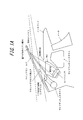
- FIG. 1A is a front view and a cross-sectional view of a display device according to a first embodiment of the present invention. It is a figure which shows sectional drawing and the graph of the display apparatus based on the 1st Example of this invention.
- FIG. 1A is a front view and a cross-sectional view of a display device according to a first embodiment of the present invention. It is a figure which shows sectional drawing and the graph of the display apparatus based on the 1st Example of this invention.
- FIG. 1 is a cross-sectional view of a display device according to a first example of the present invention.
- FIG. 1 is a cross-sectional view of a display device according to a first example of the present invention. It is the front view and sectional drawing of the display apparatus which concerns on the 2nd Example of this invention. It is a front view of the display apparatus which concerns on the 2nd Example of this invention. It is the front view and sectional drawing of the display apparatus 1 which concerns on the 3rd Example of this invention. It is a figure which shows the operation
- FIG. 2 is a cross-sectional view of the vehicle when the display device 1 according to an embodiment of the present invention is installed.
- the display device 1 is, for example, a head-up display.
- a display device 1 including a display 2 and a reflector 3, a windshield 4, a side ventilator duct 5, a defroster 6, an air outlet member (air grill) 7, and air 8 for a front defroster.
- the lower part of the display device 1 is provided inside an instrument panel 9 which houses the defroster 6 and the side ventilator duct 5 and the like.
- the display device 1 has a control unit (not shown), and performs detection of whether or not the engine is operating, and control of turning on or off the light source 23.
- the control unit is, for example, a processor such as a central processing unit (CPU).
- the display 2 includes, for example, a display unit 21, a diffusion plate 22, a light source 23, a conductive insulating sheet 24, and a heat dissipation unit 25.
- the display unit 21, the diffusion plate 22, the light source 23, and the conductive insulating sheet 24 are stacked in this order from the top.
- the display 2 may be configured only by the display unit 21, the light source 23, and the heat dissipation unit 25.
- the display 2 displays, for example, information such as the speed of a car or navigation for driving. At least a part of the display 2 is housed in the instrument panel 9.
- the display unit 21 is configured of, for example, an LCD (Liquid Crystal Display).
- the display unit 21 may be configured of an organic EL display or an inorganic EL display.
- the diffusion plate 22 diffuses the light emitted from the light source 23.
- the diffused light illuminates the surface of the display unit 21 facing the light source 23 substantially uniformly.
- the light source 23 is, for example, a light emitting diode (LED), and illuminates the display unit 21.
- the light source 23 comprises 10 LEDs.
- the conductive insulating sheet 24 is a sheet having a heat transfer function and transferring the heat from the light source 23 to the heat dissipation unit 25.
- the conductive insulating sheet 24 also has an insulating function to insulate the light source 23 and the heat radiating portion 25.
- the heat dissipation unit 25 is, for example, a heat sink.
- the heat radiating portion 25 contacts the light source 23 directly or indirectly via the conductive insulating sheet 24.
- the heat radiating portion 25 receives the heat from the light source 23 and radiates heat, so that the light source 23 is cooled.
- the heat radiating portion 25 is made of a metal such as aluminum or copper in order to enhance the heat radiating effect.
- the heat dissipating portion 25 may have a heat dissipating fin to enhance the heat dissipating effect, but does not have a heat dissipating fin for dissipating (transferring) more heat to the outside of the instrument panel 9 May be
- the heat dissipation unit 25 is connected to the heat transfer unit 32 outside the instrument panel 9 to enhance the cooling (heat dissipation) performance. Details will be described in Examples 1 to 3 described later.
- the heat radiating portion 25 is used as a fixing portion of the reflector 3 by being connected to the heat transfer portion 32 of the reflector 3.
- the heat from the light source 23 provided in the instrument panel 9 can be dissipated to the outside of the instrument panel 9 without being diffused in the instrument panel 9. Furthermore, by transferring the heat due to the heat radiation to the windshield 4, the defrosting function by the defroster 6 can be assisted. This is the same principle as a defogger that removes window fogging with heat rays.
- the reflector 3 has a reflecting member 31 and a heat transfer portion 32.
- the reflector 3 has a rectangular shape and includes a half mirror material.
- the reflector 3 is disposed close to the windshield 4 (within a predetermined distance from the windshield 4). For this reason, for example, to realize two points of extending the imaging distance and preventing reflected light to the windshield 4 on the back surface (surface on the vehicle front side) of the reflector 3 from entering the field of view of the driver.
- the reflector 3 displays the information display emitted from the display 2 in the field of view of the driver in front of the driver's seat (left side in FIG. 2), for example, as a virtual image display.
- the reflecting member 31 may be, for example, a resin half mirror material. At this time, the reflecting member 31 transmits the scenery in front of the driver and reflects the information displayed on the display 2 to be displayed together with the scenery.
- the reflecting member 31 may be opaque as long as it reflects the information displayed on the display 2. Also, the reflecting member 31 may be colored.
- the heat transfer unit 32 is made of a thermally conductive material, and is provided on a part (for example, the back surface, the periphery, etc.) of the reflection member 31. In the example of FIG. 3B, it is provided around the reflective member 31.
- the heat transfer portion 32 is connected to the heat dissipation portion 25 directly or indirectly by a conventionally known method. Further, the heat transfer unit 32 may be integrally formed with the heat dissipation unit 25. In the case of integral formation, it is expected that the heat transfer efficiency between the heat transfer portion 32 and the heat dissipation portion 25 is further enhanced.
- the windshield 4 is a partition provided in front of the vehicle, and is made of, for example, glass.
- the side ventilator duct 5 is a duct for ventilating the vehicle.
- the defroster 6 is a device for blowing hot air (air 8 for the front defroster) for clearing the windows of the windshield 4 from fogging through the air outlet member (air grille) 7.
- the warm air of the defroster 6 can also be expected to have an effect of removing dust and the like attached to the reflector 3.
- the instrument panel 9 is a panel for storing a meter 10 or the like that indicates the speed of the vehicle, the number of revolutions of the engine, the remaining amount of gasoline, and the like.
- the instrument panel 9 has an instrument panel opening 9 a for causing the reflector 3 to display the information display emitted by the display 2.
- FIG. 4A is a front view (upper left) and a cross-sectional view (lower right) of the display device 1 according to the first embodiment of the present invention.
- the front view is a view of the reflector 3 as viewed from the windshield 4 side (vehicle front side).
- the heat transfer unit 32 connected to the heat release unit 25 protrudes to the outside of the instrument panel 9.
- the heat transfer portion 32 is disposed along the back surface of the reflection member 31.
- a non-transmissive (for example, black) reflective member 31 is fixed to the surface of the heat transfer part 32 on the rear side of the heat transfer part 32 (the opposite side to the heat release part 25 with respect to the windshield 4, ie, the driver side).
- the heat release temperature at the tip of the heat transfer section 32 is expected to be, for example, equivalent to the heat generation temperature between the hot wire of the defogger and the hot wire. Since the heat release temperature of the tip of the heat transfer unit 32 to which the heat from the heat release unit 25 is transmitted is equivalent to the temperature between the heat rays, an effect of assisting the elimination of the fogging of the windshield 4 is expected.
- the heat-transfer part 32 and the windshield 4 contact by line contact or surface contact.
- the heat transfer portion 32 and the windshield 4 may be in point contact with each other.
- the heat transfer portion 32 (or the heat transfer portion 32 and the reflection member 31) warms the windshield 4 and removes fog.
- the contact is not essential, and they may be close as long as the effect of removing the windshield 4 is expected. That is, the heat transfer unit 32 may be disposed within a predetermined distance from the windshield 4.
- the heat conduction sheet 11 can be provided in the contact portion between the heat transfer portion 32 (or the heat transfer portion 32 and the reflection member 31) and the windshield 4.
- the heat transfer sheet 11 not only has an effect of efficiently transferring the heat of the heat transfer portion 32 to the windshield 4 but also a contact caused by the heat transfer portion 32 coming in contact with or away from the windshield 4 due to the sway of the vehicle.
- the effect of suppressing the sound can also be expected. That is, the effect of relieving the impact at the time of contact can also be expected using the flexibility of the heat conductive sheet 11.
- the heat transfer unit 32 is connected to the heat dissipation unit 25 for cooling the light source 23 of the display 2. Since the heat is transmitted to the outside of the instrument panel 9 by the heat transfer portion 32, the fogging of the windshield 4 can be eliminated by the heat radiation from the heat transfer portion 32 in contact with or close to the windshield 4. Furthermore, the cooling (heat radiation) performance of the light source 23 of the heat radiation unit 25 can be enhanced, and heat distortion in the instrument panel 9 can be suppressed.
- FIG. 5A is a front view (upper left) and a cross-sectional view (lower right) of a display device 1 according to a second embodiment of the present invention.
- the said front view is a figure at the time of seeing the thermal radiation part 25 from the windshield 4 side (vehicle front side).
- the heat transfer unit 32 connected to the heat release unit 25 protrudes to the outside of the instrument panel 9.
- the heat transfer unit 32 is disposed along the outer periphery of the reflection member 31. That is, the heat transfer portion 32 has a shape of a frame along the outer periphery of the reflective member 31, and the reflective member 31 inside the frame is transparent.
- the reflector 3 of the second embodiment functions as a combiner that projects the information displayed on the display 2 together with the scenery in front of the driver. According to the second embodiment, since the reflector 3 has transparency enabling visual recognition in front of the vehicle, in addition to the effects of the first embodiment, the effect that the visibility of the driver can be further improved Play.
- FIG. 5B is a diagram showing the heat resistance of the heat transfer section 32 in the second embodiment.
- the left figure is an enlarged view of the broken line in the right figure.
- the thermal resistance is a value representing the difficulty in transmitting the temperature, and indicates the amount of temperature rise per calorific value in a unit time.
- the heat resistance of the heat transfer portion 32 decreases as the cross-sectional area increases, and the heat conductivity increases.
- L ′ has a larger thermal resistance than L and a lower thermal conductivity.
- the heat transfer portion 32 does not have to be in the shape of a frame along the outer periphery of the reflector 3, and may be provided on at least a part of the reflection member 31.
- the heat transfer portion 32 may be provided along the lower side and the left and right sides except the upper side of the reflection member 31.
- the heat transfer portion 32 may have a frame shape substantially along the outer periphery of the reflector 3, the heat transfer portion 32 may have a discontinuous portion in part.
- FIG. 6 is a diagram showing a third embodiment.
- the heat radiating part 25 does not protrude outside the instrument panel 9
- the heat sink part is extended to the vicinity of the instrument panel opening 9a.
- the heat conductive translucent film 12 is attached to the heat radiating portion 25 in the instrument panel 9.
- the heat conductive light transmitting film 12 functions as the heat transfer portion 32 and is disposed along the back surface of the reflecting member 31 outside the instrument panel 9.
- the reflector 3 contacts or approaches the windshield 4.
- the transmittance of the thermally conductive translucent film 12 is 90% as an example.
- the reflector 3 of the third embodiment functions as a combiner that projects the information displayed on the display 2 together with the scenery in front of the driver.
- the thermally conductive translucent film 12 is attached to the back surface (surface on the vehicle front side) of the transparent reflecting member 31. For this reason, although the heat radiating part 25 is arrange
- the heat sink portion of the heat radiating portion 25 extends to the vicinity of the instrument panel opening 9 a to increase the contact area with the thermally conductive translucent film 12.
- the extension of the heat sink portion of the heat radiating portion 25 may not be required.
- the heat conductive light transmitting film 12 is not limited to the back surface of the reflecting member 31 and is attached to the entire reflecting member 31, the periphery of the reflecting member 31, or the surface of the reflecting member 31 (the surface on the vehicle rear side) May be
- the thermally conductive light-transmissive film 12 is, for example, a film on which a fine copper grid pattern is formed, and is a film having a high thermal conductivity with a nearly transparent appearance.
- a large crystal which can not be produced by a conventional single crystal can be produced, and has a thermal conductivity which is 10 times or more of that of optical glass and exceeds sapphire. Can be mentioned.
- FIG. 7 is a diagram showing an operation flow of de-fogging by the display device 1 according to an embodiment of the present invention.
- the control unit of the display device 1 detects that the engine is operating (step S2) while the window is still cloudy before traveling (step S1).
- the control unit detects that the defroster 6 is operating (step S3)
- the control unit confirms whether the display 2 is used (step S4).
- the control unit confirms whether or not the fogging of the windshield 4 has been eliminated (step S6).
- step S4 when the display 2 is not used (No in step S4), the control unit turns on the light source 23 to perform the heat release to assist the windshield 4 to be removed (step S5). It is checked whether the cloudiness has been eliminated (step S6). For example, the control unit determines whether or not the fogging has been eliminated based on whether or not a predetermined time (for example, 10 minutes) has elapsed since the defroster 6 is actuated. As long as the fogging is not eliminated, the control unit repeats the confirmation processing of step S6, and when the fogging is eliminated, the control unit automatically stops the defroster 6 and ends the operation flow.
- a predetermined time for example, 10 minutes
- control unit turns on the light source 23 to enable the heat dissipation by the heat dissipation unit 25, and as a result, assists the fog elimination function of the windshield 4.
- the present invention is not limited to this, and it is a display device that displays virtual light by reflecting display light from a display with a reflector, and it is necessary to remove the fogging of the windshield (for example, Applicable to aircraft and ships).
- the present invention can make various changes and modifications in arrangement and configuration based on the present disclosure, and such changes and modifications are included in the scope of the present invention.
Landscapes
- Engineering & Computer Science (AREA)
- Mechanical Engineering (AREA)
- Chemical & Material Sciences (AREA)
- Combustion & Propulsion (AREA)
- Transportation (AREA)
- Physics & Mathematics (AREA)
- General Physics & Mathematics (AREA)
- Optics & Photonics (AREA)
- Instrument Panels (AREA)
- Fittings On The Vehicle Exterior For Carrying Loads, And Devices For Holding Or Mounting Articles (AREA)
Abstract
ウィンドシールドの曇りを晴らすことを容易にする。 表示装置(1)は、情報を表示する表示器(2)と、表示器(2)で表示された情報を反射することによって運転席前方の視界内に映し出す反射体(3)とを備える表示装置(1)であって、表示器(2)は、表示部(21)と、表示部(21)を照射する光源(23)と、光源(23)から出る熱を放熱する放熱部(25)と、を備え、反射体(3)は、ウィンドシールド(4)に近接して配置され、表示器(2)で表示された情報を反射する反射部材(31)と、反射部材(31)の少なくとも一部に設けられた伝熱部(32)と、を備え、伝熱部(32)は、放熱部(25)と連結されたことを特徴とする。
Description
本発明は表示装置に関する。
従来、車両のフロントウィンド(ウィンドシールド)とは別体に設けられたコンバイナが、インストルメントパネルの上部でフロントウィンド近傍に設けられるヘッドアップディスプレイが知られている(例えば、特許文献1)。
しかしながら、例えば、特許文献1や図1A及び図1Bに示すように、インストルメントパネルの上部に設けられたコンバイナがデフロスタからの温風を遮蔽してしまい、フロントウィンドの曇りを晴らすのに時間が掛ってしまう課題があった。この課題を解決するために、コンバイナをドライバ中央(正面)から車両外側に移動する方法が考えられるが、この場合ヘッドアップディスプレイの視認性が低下する。また、デフロスタダクトの送風口をコンバイナの手前に移動する方法が考えられるが、この場合コンバイナ背面が曇り、風速分布に偏りが出てしまう。更に、特開2009-196606号公報のようにコンバイナの前後両方にデフロスタの送風口を備える方法も考えられるが、この場合デフロスタ構造が複雑化又は大型化し、スペースに余裕が無いためインストルメントパネル内の設備同士が干渉するという問題が生じる。
かかる点に鑑みてなされた本発明の目的は、ウィンドシールドの曇りを晴らすことを容易にする表示装置を提供することにある。
上記課題を解決するため、第1の観点に係る表示装置は、
情報を表示する表示器と、
該表示器で表示された情報を反射することによって運転席前方の視界内に映し出す反射体と
を備える表示装置であって、
前記表示器は、
表示部と、
該表示部を照射する光源と、
該光源から出る熱を放熱する放熱部と、を備え、
前記反射体は、
ウィンドシールドに近接して配置され、
前記表示器で表示された情報を反射する反射部材と、
該反射部材の少なくとも一部に設けられた伝熱部と、を備え、
前記伝熱部は、前記放熱部と連結されたことを特徴とする。
情報を表示する表示器と、
該表示器で表示された情報を反射することによって運転席前方の視界内に映し出す反射体と
を備える表示装置であって、
前記表示器は、
表示部と、
該表示部を照射する光源と、
該光源から出る熱を放熱する放熱部と、を備え、
前記反射体は、
ウィンドシールドに近接して配置され、
前記表示器で表示された情報を反射する反射部材と、
該反射部材の少なくとも一部に設けられた伝熱部と、を備え、
前記伝熱部は、前記放熱部と連結されたことを特徴とする。
また、上記課題を解決するため、第2の観点に係る表示装置において、
前記伝熱部は、前記放熱部と一体で形成されたことを特徴とする。
前記伝熱部は、前記放熱部と一体で形成されたことを特徴とする。
また、上記課題を解決するため、第3の観点に係る表示装置において、
前記伝熱部は、前記ウィンドシールドに接触したことを特徴とする。
前記伝熱部は、前記ウィンドシールドに接触したことを特徴とする。
また、上記課題を解決するため、第4の観点に係る表示装置において、
前記伝熱部は、熱伝導シートを介して前記ウィンドシールドに接触したことを特徴とする。
前記伝熱部は、熱伝導シートを介して前記ウィンドシールドに接触したことを特徴とする。
また、上記課題を解決するため、第5の観点に係る表示装置において、
前記光源の点灯又は消灯の制御を行う制御部を備え、
前記制御部は、
ウィンドシールドの窓曇りを晴らすデフロスタが作動している場合であって且つ前記表示器が使用されていない場合に、前記光源を点灯させることを特徴とする。
前記光源の点灯又は消灯の制御を行う制御部を備え、
前記制御部は、
ウィンドシールドの窓曇りを晴らすデフロスタが作動している場合であって且つ前記表示器が使用されていない場合に、前記光源を点灯させることを特徴とする。
第1の観点に係る表示装置によれば、ウィンドシールドの曇りを晴らすことが容易になる。
第2の観点に係る表示装置によれば、伝熱部と放熱部とが一体に形成されるので、ウィンドシールドの曇りを更に効率的に晴らすことができる。
第3の観点に係る表示装置によれば、伝熱部がウィンドシールドに接触するので、ウィンドシールドにより多くの熱が伝わり、曇りを更に効率的に晴らすことができる。
第4の観点に係る表示装置によれば、伝熱部は熱伝導シートを介してウィンドシールドに接触するので、光源の熱を効率的に伝達できるだけでなく、揺れによって伝熱部がウィンドシールドに接触したり離れたりすることで生じる接触音を抑えることもできる。
第5の観点に係る表示装置によれば、表示器が使用されていない場合であってもウィンドシールドの曇りを晴らすことができる。
以下、本発明の一実施例を図面に基づいて説明する。
図2は、本発明の一実施例に係る表示装置1を設置したときの車両の断面図である。表示装置1は例えばヘッドアップディスプレイである。図2において、表示器2と反射体3とからなる表示装置1と、ウィンドシールド4と、サイドベンチレータダクト5と、デフロスタ6と、エア吹出口部材(エアグリル)7と、フロントデフロスタ用エア8と、インストルメントパネル9と、インストルメントパネル開口部9aと、メータ10とが示される。
表示装置1の下部は、デフロスタ6及びサイドベンチレータダクト5等を収納するインストルメントパネル9の内部に設けられる。表示装置1は、制御部(図示せず)を有し、エンジンが作動しているか否かの検知及び、光源23の点灯又は消灯の制御を行う。制御部は例えばCPU(Central Processing Unit)等のプロセッサである。
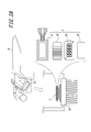
図3Aに示す通り、表示器2は例えば、表示部21と、拡散板22と、光源23と、伝導性絶縁シート24と、放熱部25とを含む。表示部21、拡散板22、光源23及び伝導性絶縁シート24はこの順番に上から積層される。表示器2は、表示部21と光源23と放熱部25のみで構成されてもよい。表示器2は、例えば自動車の速度又は運転用ナビゲーション等の情報を表示する。表示器2の少なくとも一部はインストルメントパネル9内に収納される。
表示部21は例えばLCD(Liquid Crystal Display)で構成される。表示部21は、有機ELディスプレイ又は無機ELディスプレイで構成されてもよい。
拡散板22は光源23から出た光を拡散する。拡散された光は、表示部21の光源23と対向する面を略均一に照射する。
光源23は例えばLED(Light Emitting Diode)であり、表示部21を照射する。図3Aにおいては、光源23は10個のLEDを備える。
伝導性絶縁シート24は、熱伝導機能を有し、光源23からの熱を放熱部25に伝達するシートである。また伝導性絶縁シート24は絶縁機能をも有し、光源23と放熱部25とを絶縁する。
放熱部25は例えばヒートシンクである。放熱部25は、直接的に又は伝導性絶縁シート24を介して間接的に、光源23に接触する。放熱部25は光源23から出る熱を受けて放熱するので、この結果、光源23は冷却される。好適には放熱部25は、放熱効果を高めるためアルミニウムや銅などの金属により構成する。また放熱部25は、放熱効果を高めるために放熱フィンを有してもよいが、インストルメントパネル9の外部により多くの熱を放熱(伝達)するために、放熱フィンを有さないものであってもよい。
放熱部25は、インストルメントパネル9の外部の伝熱部32と連結されて冷却(放熱)性能を高める。詳しくは後述の実施例1~3にて説明する。
また放熱部25は、反射体3の伝熱部32と連結されることで、反射体3の固定部として使用される。
上記構成によって、インストルメントパネル9内に設けられた光源23からの熱を、インストルメントパネル9内に籠らせずにインストルメントパネル9の外部に放熱することができる。更に、放熱による熱をウィンドシールド4に伝達することによって、デフロスタ6による曇り解消機能を補助することができる。これは、熱線で窓曇りを除去するデフォッガと同じ原理である。
図3Bに示す通り、反射体3は、反射部材31と伝熱部32とを有する。図3Bの例では、反射体3は矩形形状であって、ハーフミラー材を備える。図2に示すように反射体3は、ウィンドシールド4に近接して(ウィンドシールド4から所定距離内に)に配置される。このため例えば、結像距離を伸ばすこと及び反射体3の裏面(車両前方側の面)にあるウィンドシールド4への反射光がドライバの視界に入ることを防ぐこと、の2点を実現することができる。反射体3は表示器2より放射された情報表示を運転席前方(図2の左方)のドライバの視界内に例えば虚像表示により映し出す。
反射部材31は例えば樹脂製のハーフミラー材であってもよい。このとき、反射部材31はドライバ前方の風景を透過させるとともに、表示器2で表示された情報を反射して風景とともに映し出す。ここで、反射部材31は、表示器2で表示された情報を反射するものであれば不透明であってもよい。また、反射部材31は有色であってもよい。
伝熱部32は、熱伝導性の材料で構成され、反射部材31の一部(例えば裏面、周囲等)に設けられる。図3Bの例では、反射部材31の周囲に設けられている。伝熱部32は放熱部25と直接又は間接に従来公知の手法により連結される。また伝熱部32は、放熱部25と一体に形成されてもよい。一体形成の場合には、伝熱部32と放熱部25との間の熱の伝達効率が一層高まることが期待される。
再び図2を参照する。ウィンドシールド4は、車両前方に設けられる仕切りであり、例えば、ガラスからなる。サイドベンチレータダクト5は、車両内の換気を行うためのダクトである。デフロスタ6は、ウィンドシールド4の窓曇りを晴らすための温風(フロントデフロスタ用エア8)を、エア吹出口部材(エアグリル)7を通して送風する装置である。デフロスタ6の温風は、反射体3に付着した埃等を除去する効果も期待できる。
インストルメントパネル9は、車両の速度、エンジンの回転数、ガソリンの残量等を示すメータ10等を収納するパネルである。インストルメントパネル9は、表示器2により放射された情報表示を反射体3に表示させるためのインストルメントパネル開口部9aを有する。
[第1の実施例]
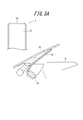
図4Aは、本発明の第1の実施例に係る表示装置1の正面図(左上の図)及び断面図(右下の図)である。当該正面図は、反射体3をウィンドシールド4側(車両前方側)から見た場合の図である。
図4Aは、本発明の第1の実施例に係る表示装置1の正面図(左上の図)及び断面図(右下の図)である。当該正面図は、反射体3をウィンドシールド4側(車両前方側)から見た場合の図である。
図4Aにおいて、放熱部25と連結された伝熱部32はインストルメントパネル9の外部に突出している。伝熱部32は反射部材31の裏面に沿うように配置される。突出した伝熱部32の車両後方側(放熱部25に対してウィンドシールド4とは反対側、すなわちドライバ側)の面に、不透過(例えば黒色)の反射部材31が固定される。
図4Bに示すように、第1の実施例の場合、表示器2の中心から伝熱部32の先端までの総距離は、10mm+30mm+100mm=140mmである。図4Bの右下のグラフに示す通り、伝熱部32の先端の放熱温度は、例えば、デフォッガの熱線と熱線の間の発熱温度相当となると見込まれる。放熱部25からの熱が伝わる伝熱部32の先端の放熱温度が熱線間の温度と同等であるため、ウィンドシールド4の曇り解消を補助する効果が見込まれる。
図4Cに示すように、伝熱部32とウィンドシールド4とは、線接触又は面接触により接触する。代替例として伝熱部32とウィンドシールド4とは点接触により接触してもよい。この構成によって、伝熱部32が(または伝熱部32および反射部材31が)ウィンドシールド4を温め、曇りを取る。なお、接触は必須ではなく、ウィンドシールド4の曇りを取る効果が見込まれる限り、それらは近接していてもよい。すなわち伝熱部32は、ウィンドシールド4から所定の距離内に配置されてもよい。
図4Dの右図に示すように、伝熱部32(または伝熱部32および反射部材31)と、ウィンドシールド4との間の接触部分には熱伝導シート11を設けることができる。熱伝導シート11は、伝熱部32の熱をウィンドシールド4に効率的に伝達する効果だけでなく、車両の揺れによって伝熱部32がウィンドシールド4に接触したり離れたりすることで生じる接触音を抑える効果も期待できる。すなわち、熱伝導シート11の柔軟性を利用し、接触時の衝撃を緩和する効果も期待できる。
第1の実施例によれば、伝熱部32は、表示器2の光源23を冷却するための放熱部25と連結される。伝熱部32によってインストルメントパネル9の外部に熱が伝わるため、ウィンドシールド4に接触又は近接した伝熱部32からの放熱によってウィンドシールド4の曇りを解消することができる。更に、放熱部25の光源23の冷却(放熱)性能を高め、インストルメントパネル9内の熱籠りを抑えることができる。
[第2の実施例]
図5Aは、本発明の第2の実施例に係る表示装置1の正面図(左上の図)及び断面図(右下の図)である。当該正面図は、放熱部25をウィンドシールド4側(車両前方側)から見た場合の図である。
図5Aは、本発明の第2の実施例に係る表示装置1の正面図(左上の図)及び断面図(右下の図)である。当該正面図は、放熱部25をウィンドシールド4側(車両前方側)から見た場合の図である。
図5Aにおいて、放熱部25と連結された伝熱部32はインストルメントパネル9の外部に突出している。伝熱部32は反射部材31の外周に沿うように配置される。つまり、伝熱部32は、反射部材31の外周に沿った枠の形状であり、その枠の内部の反射部材31は透明である。第2の実施例の反射体3は、表示器2で表示された情報をドライバ前方の風景とともに映し出すコンバイナとして機能する。第2の実施例によれば、反射体3は車両前方を視認できる透明性を有するため、第1の実施例の効果に加えて、ドライバの視認性をさらに向上させることができるとの効果を奏する。
図5Bは、第2の実施例における、伝熱部32の熱抵抗の様子を示す図である。左の図は、右の図の破線部分を拡大したものである。熱抵抗とは、温度の伝えにくさを表す値で、単位時間における発熱量あたりの温度上昇量を示す。伝熱部32は、断面積が大きいほど熱抵抗が小さくなり、熱伝導率が高くなる。ここで、第2の実施例のように伝熱部32を枠状にすると、伝熱部32の断面積は小さくなるので、熱抵抗が大きくなり、熱伝導率が低くなり得る。図5Bの例では、L’はLよりも熱抵抗が大きく、熱伝導率が低くなる。そのため、要求される熱伝導率に応じて伝熱部32の断面積を調整する必要がある。ここで、伝熱部32は、反射体3の外周に沿った枠の形状である必要はなく、反射部材31の少なくとも一部に設けられていればよい。例えば、伝熱部32は反射部材31の上辺を除く、下辺および左右の辺に沿って設けられていてもよい。また、例えば、伝熱部32はほぼ反射体3の外周に沿った枠の形状であるが、一部に不連続な部分を有していてもよい。
[第3の実施例]
図6は、第3の実施例を示す図である。図6において、放熱部25はインストルメントパネル9の外部には突出していないが、インストルメントパネル開口部9a付近までヒートシンク部分が延びている。放熱部25には、インストルメントパネル9内で熱伝導性の透光性フィルム12が貼り付けられる。熱伝導性の透光性フィルム12は伝熱部32として機能して、インストルメントパネル9の外部で反射部材31の裏面に沿うように配置される。反射体3は、ウィンドシールド4に接触又は近接する。
図6は、第3の実施例を示す図である。図6において、放熱部25はインストルメントパネル9の外部には突出していないが、インストルメントパネル開口部9a付近までヒートシンク部分が延びている。放熱部25には、インストルメントパネル9内で熱伝導性の透光性フィルム12が貼り付けられる。熱伝導性の透光性フィルム12は伝熱部32として機能して、インストルメントパネル9の外部で反射部材31の裏面に沿うように配置される。反射体3は、ウィンドシールド4に接触又は近接する。
熱伝導性の透光性フィルム12の透過率は、一例として90%である。第3の実施例の反射体3は、表示器2で表示された情報をドライバ前方の風景とともに映し出すコンバイナとして機能する。熱伝導性の透光性フィルム12は、透明な反射部材31の裏面(車両前方側の面)に貼り付けられる。このため、放熱部25はインストルメントパネル9内に配置されているが、熱伝導性の透光性フィルム12を介してインストルメントパネル9の外部に放熱を行うことができる。
第3の実施例によれば、柔軟な熱伝導性の透光性フィルム12と放熱部25とを連結させるので、第2の実施例の効果に加えて、加工が比較的容易であるとの効果を奏する。また、加工が容易であるため製造コストが抑えられる。ここで、第3の実施例では、放熱部25のヒートシンク部分がインストルメントパネル開口部9a付近まで延びて、熱伝導性の透光性フィルム12との接触面積を増加させている。しかし、熱伝導性の透光性フィルム12へ十分に熱を伝導させることができれば、放熱部25のヒートシンク部分の延長がなくてもよい。また、熱伝導性の透光性フィルム12は反射部材31の裏面に限らず、反射部材31の全体、反射部材31の周囲、または反射部材31の表面(車両後方側の面)に貼り付けられてもよい。
なお、熱伝導性の透光性フィルム12とは、一例として、微細な銅の格子パターンが形成されたフィルムであり、外観がほぼ透明の熱伝導率の高いフィルムである。また、熱伝導性の透光性フィルム12の他の例としては、従来の単結晶では不可能な大型結晶の作製が可能で、光学ガラスの10倍以上且つサファイアを超える熱伝導率を有するものが挙げられる。
[動作フロー]
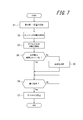
図7は、本発明の一実施例に係る表示装置1による曇り取りの動作フローを示す図である。
図7は、本発明の一実施例に係る表示装置1による曇り取りの動作フローを示す図である。
表示装置1の制御部は、走行前にまだ窓が曇っている状態において(ステップS1)、エンジンが作動していることを検知する(ステップS2)。制御部は、デフロスタ6が作動していることを検知する(ステップS3)と、表示器2が使用されているか否かを確認する(ステップS4)。表示器2が使用されている場合(ステップS4のYes)、制御部はウィンドシールド4の曇りが解消したか否かを確認する(ステップS6)。
一方、表示器2が使用されていない場合(ステップS4のNo)、制御部はウィンドシールド4の曇り取りを補助する放熱を行うために光源23を点灯させ(ステップS5)、次いでウィンドシールド4の曇りが解消したか否かを確認する(ステップS6)。例えば制御部は、曇りが解消されたか否かを、デフロスタ6が作動してから所定時間(例えば10分)が経過したか否かにより判定する。曇りが解消されない限り、制御部はステップS6の確認処理を繰り返し、曇りが解消された場合には、制御部はデフロスタ6を自動的に停止し、動作フローを終了する。
このように、表示器2が使用されていない場合であっても制御部が光源23を点灯させることで、放熱部25による放熱を可能とし、結果としてウィンドシールド4の曇り解消機能を補助することができる。
以上、本発明を車両に適用する場合について説明した。しかしながら、本発明はこれに限定されるものではなく、表示器からの表示光を反射体で反射させて虚像表示を行う表示装置であってウィンドシールドの曇りを除去する必要があるもの(例えば、航空機及び船舶等)に適用可能である。また、当業者であれば本開示に基づき配置や構成について種々の変形や修正を行うことが可能であるため、これらの変形や修正は本発明の範囲に含まれることにも留意されたい。
1 表示装置
2 表示器
3 反射体
4 ウィンドシールド
5 サイドベンチレータダクト
6 デフロスタ
7 エア吹出口部材(エアグリル)
8 フロントデフロスタ用エア
9 インストルメントパネル
9a インストルメントパネル開口部
10 メータ
11 熱伝導シート
12 熱伝導性の透光性フィルム
21 表示部
22 拡散板
23 光源
24 伝導性絶縁シート
25 放熱部
31 反射部材
32 伝熱部
2 表示器
3 反射体
4 ウィンドシールド
5 サイドベンチレータダクト
6 デフロスタ
7 エア吹出口部材(エアグリル)
8 フロントデフロスタ用エア
9 インストルメントパネル
9a インストルメントパネル開口部
10 メータ
11 熱伝導シート
12 熱伝導性の透光性フィルム
21 表示部
22 拡散板
23 光源
24 伝導性絶縁シート
25 放熱部
31 反射部材
32 伝熱部
Claims (5)
- 情報を表示する表示器と、
該表示器で表示された情報を反射することによって運転席前方の視界内に映し出す反射体と、を備える表示装置であって、
前記表示器は、
表示部と、
該表示部を照射する光源と、
該光源から出る熱を放熱する放熱部と、を備え、
前記反射体は、
ウィンドシールドに近接して配置され、
前記表示器で表示された情報を反射する反射部材と、
該反射部材の少なくとも一部に設けられた伝熱部と、を備え、
前記伝熱部は、前記放熱部と連結されたことを特徴とする表示装置。 - 請求項1に記載の表示装置において、
前記伝熱部は、前記放熱部と一体で形成されたことを特徴とする表示装置。 - 請求項1に記載の表示装置において、
前記伝熱部は、前記ウィンドシールドに接触したことを特徴とする表示装置。 - 請求項3に記載の表示装置において、
前記伝熱部は、熱伝導シートを介して前記ウィンドシールドに接触したことを特徴とする表示装置。 - 請求項1に記載の表示装置において、
前記光源の点灯又は消灯の制御を行う制御部を備え、
前記制御部は、
ウィンドシールドの窓曇りを晴らすデフロスタが作動している場合であって且つ前記表示器が使用されていない場合に、前記光源を点灯させることを特徴とする表示装置。
Priority Applications (1)
| Application Number | Priority Date | Filing Date | Title |
|---|---|---|---|
| JP2017511458A JP6360251B2 (ja) | 2015-04-09 | 2016-03-16 | 表示装置 |
Applications Claiming Priority (2)
| Application Number | Priority Date | Filing Date | Title |
|---|---|---|---|
| JP2015080105 | 2015-04-09 | ||
| JP2015-080105 | 2015-04-09 |
Publications (1)
| Publication Number | Publication Date |
|---|---|
| WO2016163078A1 true WO2016163078A1 (ja) | 2016-10-13 |
Family
ID=57071833
Family Applications (1)
| Application Number | Title | Priority Date | Filing Date |
|---|---|---|---|
| PCT/JP2016/001522 Ceased WO2016163078A1 (ja) | 2015-04-09 | 2016-03-16 | 表示装置 |
Country Status (2)
| Country | Link |
|---|---|
| JP (1) | JP6360251B2 (ja) |
| WO (1) | WO2016163078A1 (ja) |
Cited By (1)
| Publication number | Priority date | Publication date | Assignee | Title |
|---|---|---|---|---|
| WO2020162489A1 (ja) * | 2019-02-06 | 2020-08-13 | 日本精機株式会社 | 表示装置 |
Citations (3)
| Publication number | Priority date | Publication date | Assignee | Title |
|---|---|---|---|---|
| JPS63121530A (ja) * | 1986-11-12 | 1988-05-25 | Nissan Motor Co Ltd | 車両用表示装置 |
| JP2009222880A (ja) * | 2008-03-14 | 2009-10-01 | Fujinon Corp | ヘッドアップディスプレイ装置 |
| JP2015020624A (ja) * | 2013-07-19 | 2015-02-02 | トヨタ自動車株式会社 | インストルメントパネル構造 |
Family Cites Families (1)
| Publication number | Priority date | Publication date | Assignee | Title |
|---|---|---|---|---|
| JP6107380B2 (ja) * | 2013-04-25 | 2017-04-05 | 日本精機株式会社 | ヘッドアップディスプレイ装置 |
-
2016
- 2016-03-16 JP JP2017511458A patent/JP6360251B2/ja not_active Expired - Fee Related
- 2016-03-16 WO PCT/JP2016/001522 patent/WO2016163078A1/ja not_active Ceased
Patent Citations (3)
| Publication number | Priority date | Publication date | Assignee | Title |
|---|---|---|---|---|
| JPS63121530A (ja) * | 1986-11-12 | 1988-05-25 | Nissan Motor Co Ltd | 車両用表示装置 |
| JP2009222880A (ja) * | 2008-03-14 | 2009-10-01 | Fujinon Corp | ヘッドアップディスプレイ装置 |
| JP2015020624A (ja) * | 2013-07-19 | 2015-02-02 | トヨタ自動車株式会社 | インストルメントパネル構造 |
Cited By (1)
| Publication number | Priority date | Publication date | Assignee | Title |
|---|---|---|---|---|
| WO2020162489A1 (ja) * | 2019-02-06 | 2020-08-13 | 日本精機株式会社 | 表示装置 |
Also Published As
| Publication number | Publication date |
|---|---|
| JPWO2016163078A1 (ja) | 2018-02-01 |
| JP6360251B2 (ja) | 2018-07-18 |
Similar Documents
| Publication | Publication Date | Title |
|---|---|---|
| JP6642172B2 (ja) | ヘッドアップディスプレイ装置 | |
| EP3528043B1 (en) | Projector and head-up display device including projector | |
| US11971545B2 (en) | Vehicular display device | |
| CN113376835B (zh) | 车辆用显示装置 | |
| JP2017537354A (ja) | バックライト装置、とりわけヘッドアップディスプレイ用のバックライト装置及び自動車用ヘッドアップディスプレイ | |
| US20160320691A1 (en) | Device for the emission of light, in particular for the generation of an image | |
| WO2016121269A1 (ja) | 車両用ヘッドアップディスプレイ装置 | |
| JP2010167830A (ja) | 車両用ヘッドアップディスプレイ装置 | |
| JP6451981B2 (ja) | ヘッドアップディスプレイ装置 | |
| JP2004347633A (ja) | ヘッドアップディスプレイ装置 | |
| JP2009222880A (ja) | ヘッドアップディスプレイ装置 | |
| JP6360251B2 (ja) | 表示装置 | |
| JP2015020624A (ja) | インストルメントパネル構造 | |
| JP6341866B2 (ja) | ヘッドアップディスプレイ設置構造 | |
| JP6046340B2 (ja) | 車両用表示装置 | |
| JP7474028B2 (ja) | ヘッドアップディスプレイ | |
| JP2018087775A (ja) | 車両用表示装置 | |
| JP5961372B2 (ja) | 車両用表示装置 | |
| CN120530355A (zh) | 图像生成装置和包括这种装置的平视显示器 | |
| JP6046368B2 (ja) | 車両用表示装置 | |
| JP6398466B2 (ja) | 表示装置 | |
| JP2016060333A (ja) | 表示装置 | |
| CN220913442U (zh) | 一种图像源及平视显示器 | |
| US20260093146A1 (en) | Thermal management of a heads-up display using a thermally conductive bezel | |
| JP2026030849A (ja) | 画像表示装置 |
Legal Events
| Date | Code | Title | Description |
|---|---|---|---|
| 121 | Ep: the epo has been informed by wipo that ep was designated in this application |
Ref document number: 16776256 Country of ref document: EP Kind code of ref document: A1 |
|
| ENP | Entry into the national phase |
Ref document number: 2017511458 Country of ref document: JP Kind code of ref document: A |
|
| NENP | Non-entry into the national phase |
Ref country code: DE |
|
| 122 | Ep: pct application non-entry in european phase |
Ref document number: 16776256 Country of ref document: EP Kind code of ref document: A1 |