WO2016162901A1 - 眼鏡型表示装置 - Google Patents
眼鏡型表示装置 Download PDFInfo
- Publication number
- WO2016162901A1 WO2016162901A1 PCT/JP2015/001965 JP2015001965W WO2016162901A1 WO 2016162901 A1 WO2016162901 A1 WO 2016162901A1 JP 2015001965 W JP2015001965 W JP 2015001965W WO 2016162901 A1 WO2016162901 A1 WO 2016162901A1
- Authority
- WO
- WIPO (PCT)
- Prior art keywords
- glasses
- user
- type display
- display device
- unit
- Prior art date
- Legal status (The legal status is an assumption and is not a legal conclusion. Google has not performed a legal analysis and makes no representation as to the accuracy of the status listed.)
- Ceased
Links
Images













Classifications
-
- G—PHYSICS
- G02—OPTICS
- G02B—OPTICAL ELEMENTS, SYSTEMS OR APPARATUS
- G02B27/00—Optical systems or apparatus not provided for by any of the groups G02B1/00 - G02B26/00, G02B30/00
- G02B27/01—Head-up displays
- G02B27/017—Head mounted
- G02B27/0176—Head mounted characterised by mechanical features
-
- G—PHYSICS
- G02—OPTICS
- G02B—OPTICAL ELEMENTS, SYSTEMS OR APPARATUS
- G02B27/00—Optical systems or apparatus not provided for by any of the groups G02B1/00 - G02B26/00, G02B30/00
- G02B27/01—Head-up displays
- G02B27/017—Head mounted
- G02B27/0172—Head mounted characterised by optical features
-
- G—PHYSICS
- G02—OPTICS
- G02B—OPTICAL ELEMENTS, SYSTEMS OR APPARATUS
- G02B27/00—Optical systems or apparatus not provided for by any of the groups G02B1/00 - G02B26/00, G02B30/00
- G02B27/01—Head-up displays
- G02B27/0179—Display position adjusting means not related to the information to be displayed
-
- G—PHYSICS
- G02—OPTICS
- G02C—SPECTACLES; SUNGLASSES OR GOGGLES INSOFAR AS THEY HAVE THE SAME FEATURES AS SPECTACLES; CONTACT LENSES
- G02C5/00—Constructions of non-optical parts
- G02C5/02—Bridges; Browbars; Intermediate bars
- G02C5/04—Bridges; Browbars; Intermediate bars with adjustable means
- G02C5/045—Bridges; Browbars; Intermediate bars with adjustable means for varying the horizontal distance of the lenses
-
- G—PHYSICS
- G02—OPTICS
- G02C—SPECTACLES; SUNGLASSES OR GOGGLES INSOFAR AS THEY HAVE THE SAME FEATURES AS SPECTACLES; CONTACT LENSES
- G02C5/00—Constructions of non-optical parts
- G02C5/12—Nose pads; Nose-engaging surfaces of bridges or rims
- G02C5/122—Nose pads; Nose-engaging surfaces of bridges or rims with adjustable means
- G02C5/124—Nose pads; Nose-engaging surfaces of bridges or rims with adjustable means for vertically varying the position of the lenses
-
- G—PHYSICS
- G02—OPTICS
- G02C—SPECTACLES; SUNGLASSES OR GOGGLES INSOFAR AS THEY HAVE THE SAME FEATURES AS SPECTACLES; CONTACT LENSES
- G02C5/00—Constructions of non-optical parts
- G02C5/14—Side-members
- G02C5/20—Side-members adjustable, e.g. telescopic
-
- H—ELECTRICITY
- H04—ELECTRIC COMMUNICATION TECHNIQUE
- H04N—PICTORIAL COMMUNICATION, e.g. TELEVISION
- H04N5/00—Details of television systems
- H04N5/74—Projection arrangements for image reproduction, e.g. using eidophor
- H04N5/7475—Constructional details of television projection apparatus
- H04N5/7491—Constructional details of television projection apparatus of head mounted projectors
-
- G—PHYSICS
- G02—OPTICS
- G02B—OPTICAL ELEMENTS, SYSTEMS OR APPARATUS
- G02B27/00—Optical systems or apparatus not provided for by any of the groups G02B1/00 - G02B26/00, G02B30/00
- G02B27/01—Head-up displays
- G02B27/017—Head mounted
- G02B2027/0178—Eyeglass type
-
- H—ELECTRICITY
- H04—ELECTRIC COMMUNICATION TECHNIQUE
- H04N—PICTORIAL COMMUNICATION, e.g. TELEVISION
- H04N5/00—Details of television systems
- H04N5/64—Constructional details of receivers, e.g. cabinets or dust covers
Definitions
- the present invention relates to a glasses-type display device mounted on a head.
- Patent Documents 1 to 3 In recent years, development of a glasses-type display device in which a small display device is incorporated in a glasses-type frame and an image is projected within the field of view of the user has been advanced (see, for example, Patent Documents 1 to 3).
- an eyepiece lens for projecting an image is provided on the lower rim of the eyeglass frame, and the user can observe the image only when the user directs his / her line of sight to the eyepiece lens It has become.
- the glasses-type display device can mount the display device on the head of the user in the same manner as wearing general glasses, without requiring a complicated mounting mechanism.
- a compact image display unit that does not interfere with the peripheral vision of the user Is used.
- the area (eye box) in which the user can visually recognize the image is necessarily narrowed.
- alignment adjustment hereinafter referred to simply as position adjustment
- position adjustment is accurately performed so that the position of the user's eye falls within the area where the image can be viewed according to the individual difference.
- An adjustment mechanism is needed.
- the front portion (eyeglass front portion) of the eyeglass frame provided with the display unit can be rotationally adjusted with the pivot axis at the eyeball center in side view. And adjust the incident angle of the image to the eye.
- the position adjustment unit is provided so that the user can adjust the position of the nose pad.
- the position where the image can be seen can be moved up and down, but alignment adjustment can not be performed.
- the entire front portion of the glasses is largely deviated and inclined with respect to the extending direction of the temples of the glasses, which causes an uncomfortable feeling in appearance.
- the nose pad since the positional relationship between the nose pad and the nose is also shifted by the adjustment for rotating the front part of the glasses, the nose pad does not contact the nose depending on the state of inclination of the front part of the glasses with respect to the temples. For this reason, there is a concern that the wearing condition of the glasses-type image display device on the head of the user may be unstable, and the accuracy of positioning may be reduced.
- the position adjustment of the nose pad in the prior art mainly aims to adjust the user's wearing feeling, and it is not possible to simultaneously adjust both the display image position and the wearing feeling.
- an object of the present invention made focusing on these points is to provide a glasses-type display device capable of adjusting the display image with respect to the position of the user's eye with high accuracy.
- the invention of the eyeglass display device to achieve the above object is Glasses front located in front of the user's eyes, Left and right temples connected to the front of the glasses and worn on the head of the user; An angle adjustment unit configured to adjust an inclination of the glasses front portion by rotating the glasses front portion with respect to the left and right temple portions; And an image display unit fixed to the front of the glasses and projecting image light onto the eye of the user, wherein the angle adjustment unit has a central axis of rotation that is closer to the eye center of the user in side view It is characterized by being located in the glasses front part side.
- the spectacles front portion includes a rim portion, and the image display portion is disposed on a surface on the user side of the rim portion.
- the central axis of the said rotation of the said angle adjustment part is located in the vicinity of the said image display part in a side view.
- left and right temples can be configured to be stretchable.
- the image display device can include a nose pad that contacts the user's nose, and a height position adjustment mechanism that adjusts the height position of the nose pad with respect to the glasses front portion.
- a spectacles front part means the front part of spectacles, and the flame
- the vicinity of the image display unit means that the distance from the image light emission portion of the image display unit is within 12 mm.
- the eyeglass front portion is provided with an angle adjusting portion for adjusting the inclination of the eyeglass front portion by rotating the eyeglass front portion with respect to the left and right temple portions. Since the eyeglass is located closer to the front of the glasses than the eyeball center of the user in view, adjustment of the display image, in particular, vertical position adjustment, can be performed accurately with respect to the position of the user's eyes.
- FIG. 1 It is a perspective view of a glasses type display concerning a 1st embodiment. It is a figure explaining the structure of the connection part of the spectacles front part of FIG. 1, and a temple part, (a) is a top view, (b) is a side view. It is a figure which shows the state which mounted
- FIG. 1 is a perspective view of a glasses-type display device 10 according to a first embodiment of the present invention, as viewed from the back side of the glasses.
- the eyeglass-type display device 10 includes an eyeglass portion configured to include left and right temples 11 and an eyeglass front portion 12, and an image display unit 20.
- the temple portion 11 is for wearing the glasses-type display device 10 by being hung on the user's ear, as with ordinary glasses.
- the glasses front portion 12 is a front portion of the glasses disposed in front of the user's eyes, and includes left and right rim portions 13, bridge portions 14, left and right lenses 15, and left and right nose pads 16.
- the left and right rims 13 surround and hold the left and right lenses 15, respectively.
- the bridge portion 14 is located at the center of the left and right rim portions 13 surrounding the left and right lenses 15 and connects them.
- the nose pads 16 are provided on portions of the left and right rims 13 that come in contact with the user's nose.
- the side facing the front is called the front side
- the side facing the user's face is called the back side.
- upper, lower, right, left, horizontal, vertical, and the like indicate directions in a state where the user wears the glasses-type display device 10.
- An image display unit 20 is provided on the upper rim portion 13 of one lens 15 (the right side lens in the drawing).
- the image display unit 20 can be formed integrally with the rim portion 13.
- display elements such as an LCD and an organic EL (not shown) are built in and fixed.
- the image display unit 20 guides the image light of the image of the display element by the internal optical system, and uses it from the eyepiece optical unit 22 configured by an eyepiece lens or the like disposed above the central portion of one lens 15 Project towards the eyes of the person. Thereby, the user can observe the image displayed on the display element as a virtual image.
- the image display unit 20 is disposed on the back side of the rim 13 so as not to be seen from the front. Thereby, the glasses-type display device 10 has an appearance almost indistinguishable from that of ordinary glasses when worn.
- Data of an image displayed on a display element in the image display unit 20 is supplied from the signal processing unit 21 mounted on the temple unit 11 via a flexible wiring (not shown).
- transmission of image data is not limited to this, and transmission may be performed from a portable information terminal such as a mobile phone owned by the user to the image display unit 20 by wired or wireless communication means. In that case, it is not necessary to arrange the signal processing unit 21.
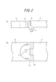
- FIG. 2A and 2B are diagrams for explaining the configuration of the connection portion 17.
- FIG. 2A is a top view
- FIG. 2B is a side view seen from the side in contact with the user at the time of wearing.
- the rim portion 13 and the temple portion 11 are connected via an intermediate member 25.
- the intermediate member 25 and the rim portion 13 are connected by a hinge having a hinge shaft 26, as in the connection of the rim portion and the temple portion in ordinary glasses.
- the hinge shaft 26 extends in the vertical direction, and enables the temple portion 11 of the glasses-type display device 10 to be folded in the horizontal direction.
- connection between the rim portion 13 and the intermediate member 25 is configured such that the glasses front portion 12 can be tilted with respect to the temple portion 11. Specifically, it is the following.
- the end on the intermediate member 25 side of the rim portion 13 is formed with a notch having a predetermined thickness having an arc whose outer shape is a semicircular shape on the surface facing the user side.
- the rim 13 side end of the intermediate member 25 has a plate-like portion having a circular arc having substantially the same radius as the notch of the rim 13, and the notch of the rim 13 is an arc. The part is slidably fitted.
- the intermediate member 25 is pivotally supported by the rim portion 13 with respect to the center of the circular arc by a rotation shaft 27 (central axis of rotation) such as a pin. Since the pivot shaft 27 extends in the horizontal direction, the rim portion 13 is supported rotatably relative to the intermediate member 25 in the vertical direction. Note that the posture between the rim portion 13 and the intermediate member 25 is held mutually by an appropriate frictional force or the like.
- the connection part of the rim part 13 and the intermediate member 25 comprises an angle adjustment part.
- FIG. 3 is a view showing the glasses-type display device 10 of FIG. 1 worn on a user.
- the user wears the glasses-type display device 10 in a state where the back side of the temple portion 11 is put on the ear 32 and the nose pad (not shown in FIG. 3) of the glasses front portion 12 is in contact with the nose 33.
- the pivot shaft 27 is located closer to the eyeglass front portion 12 than the eyeball center O of the user.
- the pivot shaft 27 is located near the eyepiece optical unit 22 in side view.
- the vicinity of the eyepiece optical unit 22 means that the distance from the eyepiece optical unit 22 is 12 mm or less in side view.
- the distance between the lens of the glasses and the eye 31 is about 12 mm, and the radius of the human eye is also about 12 mm.
- the rotation axis 27 of the angle adjustment unit coincides with the eyeball center O in side view, the light beam along the optical axis of the image light emitted from the eyepiece optical unit even when the glasses front unit 12 is rotated (Hereinafter, simply an exit ray) does not pass through the eye center O, and alignment adjustment can not be performed.
- the distance between the rotation shaft 27 and the eyepiece optical unit 22 is smaller than 12 mm, which is a half of 24 mm that is the distance from the lens to the eyeball center O, the effect of position adjustment by rotation is considered to be large.
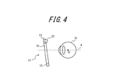
- FIG. 4 is a view for explaining the relationship between the position and the orientation of the eyeglass front portion 12 and the eyeball 31 when viewed from the front.
- FIG. 5 is a figure explaining the relationship of the position and direction of the spectacles front part 12 and the eyeball 31 at the time of display image visual recognition.
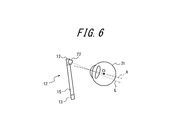
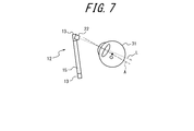
- FIG. 6 and FIG. 7 are diagrams showing an example of the state in which the position adjustment between the glasses-type display device 10 and the eyeball 31 is out.
- an emitted light beam L emitted from the eyepiece optical unit 22 and passing through the pupil of the user's eye 31 passes below the eyeball center O.
- an image lacking the upper side is projected on the field of view of the user.
- an emitted light beam L emitted from the eyepiece optical unit 22 and passing through the pupil of the user's eye 31 passes the upper side of the eyeball center O. In this case, an image whose lower side is missing is projected on the user's view.
- FIG. 8 is a view for explaining position adjustment by rotating the glasses front part 12.
- the user rotates the eye 31 to set the visual axis A by turning the eyeglass front portion 12 and setting the direction of the emitted light L emitted from the eyepiece optical portion 22 to pass through the eyeball center O of the eye 31. It is possible to view the display image from the eyepiece optical unit 22 toward the eyepiece optical unit 22.
- the angle adjustment unit for adjusting the inclination of the glasses front unit 12 is provided by rotating the glasses front unit 12 with respect to the left and right temples 11, and the angle adjustment is performed. Since the rotation axis 27 for adjusting the inclination is positioned closer to the eyeglass front portion 12 than the eyeball center O of the user in side view, the display image can be well viewed with respect to the position of the user's eye The position adjustment can be performed accurately. In addition, since the eyepiece optical unit 22 is disposed on the user side surface of the rim portion 13, the eyepiece optical portion 22 is hidden behind the rim portion 13 when viewed from the front.
- the position adjustment of the eyepiece optical unit 22 is performed only by rotating the glasses front unit 12 with respect to the temple unit 11.
- the viewing state of the display image can be improved also by moving the eyepiece optical unit 22 back and forth or up and down without changing the direction of the eyepiece optical unit 22.
- the emitted light beam L can be made to pass through the eyeball center O by moving the eyepiece 31 side horizontally without changing the direction of the eyepiece optical unit 22 in FIG.
- the emitted light beam L can be made to pass through the eyeball center O by shifting it upward without changing the direction of the eyepiece optics 22.
- the adjustment of the display image is performed by combining the horizontal movement and / or the vertical position adjustment of the eyepiece optical unit 22 and the rotation around the rotation axis 27.
- FIG. 9 is a view showing a state in which the glasses-type display device 10A according to the second embodiment is attached to the user.
- the eyeglass-type display device 10A is different from the eyeglass-type display device 10 according to the first embodiment in the temple portion 41.
- the temple portion 41 is composed of a first portion 41 a on the side of the glasses front portion 12 and a second portion 41 b including an ear hook portion located behind the first portion 41 a.
- the back side portion of the first portion 41 a is provided with a cavity along the longitudinal direction of the temple portion 41. That is, the rear portion of the first portion 41a is sheath-shaped.
- the front portion of the second portion 41b is slightly smaller than the hollow portion of the first portion 41a, and is configured to be slidable inside the first portion 41a.
- the second portion 41b is configured not to leave the first portion 41a.
- the temple part 41 is comprised so that expansion-contraction is possible as a whole.
- a mechanism for fixing the first portion 41a and the second portion 41b to each other may be provided so that the positional relationship between the first portion 41a and the second portion 41b does not change.
- the other configuration is the same as that of the first embodiment, so the same reference numerals are given to the same components and the description will be omitted.
- the glasses-type display device 10A can adjust the distance between the eyeglass front portion 12 and the eyeball 31 by expanding and contracting the temple portion 41 as necessary. For example, when the light emitted from the eyepiece 22 passes the upper side of the eyeball center O and the lower side of the image viewed by the user is chipped, the temple 41 is extended to move the glasses front 12 away and the light is emitted. Is adjusted so that it passes through the eyeball center O. By this, it is possible to adjust the position so that the display image can be viewed well.
- FIG. 10 is a view showing a state in which the glasses-type display device 10B according to the third embodiment is attached to the user.
- the spectacles type display device 10B also differs in the temple portion 42 from the spectacles type display device 10 according to the first embodiment.
- the temple part 42 is comprised from the 1st part 42a, the 2nd part 42b, and the 3rd part 42c in an order from the spectacles front part 12 side.
- a first pivoting shaft 43a is provided between the first portion 42a and the second portion 42b, and is rotatably connected with each other around the first pivoting shaft 43a within a predetermined range.
- a second pivot shaft 43b is provided between the second portion 42b and the third portion 42c, and is connected to be rotatable around the second pivot shaft 43b within a predetermined range.
- the glasses-type display device 10B adjusts the height of the third portion 42c of the temple portion 42 to increase the height of the ear hook portion Can be adjusted.
- the same wearing feeling can be provided to anyone, and the inclination of the glasses front portion 12 can be adjusted as in the first embodiment.
- the mutual inclination of the first portion 42a, the second portion 42b, and the third portion 42c of the temple portion 42 for example, the rear end portion of the first portion 42a is pushed down or You can push it up. This also enables adjustment of the inclination of the glasses front portion 12.
- FIG. 11 is a view showing a state in which the glasses-type display device 10C according to the fourth embodiment is worn on the user.
- the temple portion 44 of the spectacles-type display device 10C includes a first portion 44a and a second portion 44b, and the portion between the first portion 44a and the second portion 44b can be pivoted within a predetermined range by the pivot shaft 45. It is connected to the.
- the other configuration is the same as that of the first embodiment, so the same reference numerals are given to the same components and the description will be omitted.
- the eyeglass-type display device 10C according to the fourth embodiment has a simpler configuration than the eyeglass-type display device 10B according to the third embodiment, and adjustment of the height position of the user's ear 32 is performed. It is made possible.
- FIG. 12 is a view for explaining the height position adjustment mechanism of the nose pad 16 of the glasses-type display device according to the fifth embodiment.
- This figure is a perspective view of the nose pad 16 as seen from the opposite side of the part abutting on the nose.
- the nose pad 16 is constituted by the slide part 46 and the nose pad 47.
- the slide part 46 is connected to the nose-side facing portion of the rim portion 13 via the pad arm 48.
- the nose pad 47 is provided with a slide groove 49.
- the slide groove 49 is formed with a large number of wavelike irregularities along the side surfaces 49a and 49b extending in the longitudinal direction of the slide groove 49, and the interval between the side surfaces is periodically changed in the longitudinal direction.
- a plate spring elastic member
- the slide part 46 is configured to slide along the slide groove 49 so that the leaf spring does not separate from the slide groove 49.
- the height position adjustment mechanism is used to adjust the position of the nose pad 16 in the vertical direction with respect to the glasses front unit 12. Adjusting the inclination and position of the glasses front portion 12 so as to obtain a good image while adjusting the wearing feeling of the glasses-type display device of the user to a preferable state by providing the height position adjusting mechanism Can.
- the length of the temple portion 41 is determined, and the height position adjustment of the nose pad 16 is performed according to the length of the temple portion 41. adjust. This makes it possible to observe a good image.
- the contact of the nose pad 16 with the nose and the distance between the lens 15 and the eye 31 affect the wearing feeling of the glasses-type display device. For this reason, in these adjustments, position adjustment is performed in which the goodness of the wearing feeling is emphasized more than the display condition of the image.
- the glasses front portion 12 is adjusted to rotate around the pivot shaft 27 and fixed at a position where the best image can be visually recognized.
- the glasses-type display device can be adjusted to the best condition. Further, since the height position adjustment mechanism of the present embodiment slides the slide part 46 to the groove provided in the nose pad 47, it is small and hidden in the rim portion 13 when viewed from the front, so that the appearance is improved. It also has the advantage of being unobtrusive.
- the lens may or may not have a power, and if the user does not need it, the lens may not be present, and in that case the glasses front part is mainly composed of a frame Ru. Also, if the intermediate member is directly connected to the lens, the rim portion may not be necessary. In that case, a direct image display unit is provided along the lens.
- the image display unit may be provided on either the right or left eye side, or a total of two image display units may be provided corresponding to both eyes.
- the image display unit is not limited to the configuration in which it is superimposed on the rim on the upper side of the lens, and may be disposed so as to overlap on the rim on the lower side when viewed from the front. Alternatively, it can be placed at any position close to the rim or lens.
- the mechanism which rotates a spectacles front part with respect to a temple part can have various methods besides the thing of an illustration.
- the bridge adjustment unit that adjusts the relative positions of the left and right spectacle lens units performs eye point adjustment according to the individual difference of the user.
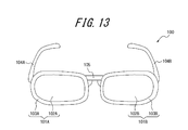
- FIG. 13 is a front perspective view showing a schematic configuration of the glasses-type display device 100 according to the first reference example.
- FIG. 14 is a rear perspective view showing a schematic configuration of the glasses-type display device 100 according to the first reference example.
- the eyeglass-type display device 100 is connected to the eyeglass lens portions 101A and 101B disposed in front of the left and right eyes of the user and the eyeglass lens portion, and the temple portion attached to the head of the user 104A, 104B, bridge portion 105 interposed between the spectacle lens portions 101A and 101B, hinge portions 106A, 106B foldably connecting the temple portions 104A, 104B to the spectacle lens portions 101A, 101B, and users And a display device (image display unit) 110 for displaying an image.
- the spectacle lens unit 101A is disposed in front of the user's right eye, and includes a spectacle lens 102A and a rim unit 103A that holds the spectacle lens 102A.
- the spectacle lens unit 101B is disposed in front of the user's left eye, and includes a spectacle lens 102B and a rim unit 103B that holds the spectacle lens 102B.
- the eyeglass lens portions 101A and 101B are not limited to the configuration including both the eyeglass lens and the rim portion, and may be only one of the eyeglass lens and the rim portion.
- it may be a spectacles type display device which does not have a rim portion for holding a spectacle lens (rimless).
- it may be a spectacles-type display device which has no spectacle lens and the spectacle lens part comprises only the rim part.
- the display device (image display unit) 110 includes a main body unit 111 having a display element, and an eyepiece optical unit 112 that projects image light from the display element onto the eye E1 of the user.
- the main body portion 111 is disposed on the side surface of the rim portion 103A on the user side.
- the eyepiece optical unit 112 is disposed along the rim portion 103A on the side surface of the rim portion 103A on the user side.
- the glasses-type display device 100 is a wearable device that does not deteriorate the appearance.
- a battery or the like for supplying power to the display element may be built in the rim portion 103A or the temple portion 104A, or may be wired from an external device.
- FIG. 15 is a top view for explaining the bridge adjustment unit 107 of the glasses-type display device 100 according to the first reference example.
- FIG. 15 shows a case where the user with the eye width L1 wears the glasses-type display device 100 and a case where the user with the eye width L2 longer than the eye width L1 wears the glasses-type display device 100.
- the bridge unit 105 includes a bridge adjusting unit 107 including a slide shaft 107A and slide shaft fixing units 107B and 107C for fixing the slide shaft 107A.
- the slide shaft fixing portions 107B and 107C are fixed to the rim portions 103A and 103B, respectively.
- the slide shaft fixing portions 107B and 107C each have a hole. Both ends of the slide shaft 107A are inserted into the holes of the slide shaft fixing portions 107B and 107C and fixed.
- the bridge adjustment unit 107 adjusts the eye point corresponding to each of the user with the eye width L1 and the user with the eye width L2 by moving the slide shaft fixing portions 107B and 107C along the slide shaft 107A. it can.
- the distance between the slide shaft fixing portions 107B and 107C is longer than when the user with the eye width L1 wears the glasses-type display device 100.
- the slide shaft fixing portions 107B and 107C are moved along the slide shaft 107A.
- the slide shaft fixing portions 107B and 107C are fixed to the rim portions 103A and 103B, by moving the slide shaft fixing portions 107B and 107C so as to increase the distance between them, the distance between the rim portions 103A and 103B is also become longer. In other words, the relative positions of the left and right rim portions 103A and 103B are adjusted. Since the eyepiece optical unit 112 for projecting the image light onto the eyeball of the user is disposed on the side of the rim unit 103A on the user side, when the distance between the rim units 103A and 103B becomes longer, the eyepiece optical unit 112 also becomes a rim It moves along with the part 103A.
- the bridge adjustment unit 107 can adjust the eye point from the position according to the eye width L1 to the position according to the eye width L2.
- the eyeglass-type display device 100 of the present embodiment can be adjusted in eye point with a simple configuration, and the appearance is not different from general glasses, and the appearance is not impaired.
- FIG. 16 is a top view for explaining the bridge adjustment unit 207 of the glasses-type display device 200 according to the second reference example.
- FIG. 16 shows the case where the user with the eye width L1 wears the glasses-type display device 200 and the case where the user with the eye width L2 longer than the eye width L1 wears the glasses-type display device 200.
- the structure of the bridge adjustment unit 207 is different from that of the glasses-type display device 100 according to the first reference example.
- the other configuration is the same as that of the first reference example.
- the bridge adjustment unit 207 includes an intervening portion 207A which is an elastic member (plastic member) such as a wire or rubber, and fixing portions 207B and 207C to which both ends of the intervening portion 207A are fixed.
- the fixing portions 207B and 207C are fixed to the rim portions 103A and 103B, respectively.
- the bridge adjustment unit 207 can adjust the eye point corresponding to each of the user with the eye width L1 and the user with the eye width L2 by deforming the shape of the intervening portion 207A.
- the distance between the fixing portions 207B and 207C becomes longer than when the user of the eye width L1 wears the glasses-type display device 200.
- the shape of the intervening portion 207A is deformed. Since the fixing portions 207B and 207C are fixed to the rim portions 103A and 103B, the distance between the rim portions 103A and 103B is also changed by deforming the shape of the intervening portion 207A so that the distance between the fixing portions 207B and 207C becomes long. become longer.
- the relative positions of the left and right eyeglass lens portions 101A and 102B are adjusted. Since the eyepiece optical unit 112 for projecting the image light onto the eye E1 of the user is disposed on the side of the rim 103A on the user side, when the distance between the rims 103A and 103B becomes long, the eyepiece optical unit 112 is also It moves along with the rim portion 103A. Thus, in the glasses-type display device 200 of the present reference example, the bridge adjustment unit 207 can adjust the eye point from the position according to the eye width L1 to the position according to the eye width L2.
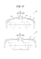
- FIG. 17 is a top view for explaining the bridge adjustment unit 207 of the glasses-type display device 200 according to the second reference example.
- FIG. 17 shows the case where the user with the eye width L1 wears the glasses-type display device 200 and the case where the user with the eye width L2 longer than the eye width L1 wears the glasses-type display device 200.
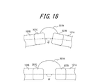
- FIG. 18 is an enlarged view of the bridge adjustment unit 207 of the glasses-type display device 200 of the second reference example. The configuration is the same as that of the glasses-type display device 200 shown in FIG.
- the bridge adjustment unit 207 of the present reference example changes the emission angle of the image light emitted from the eyepiece optical system 112 with respect to the eye E1 of the user together with the position of the eyepiece optical system 112 by deforming the shape of the intervening portion 207A. You can also. Thus, it is possible to adjust the eye point corresponding to each of the user of the eye width L1 and the user of the eye width L2.
- the angle formed by the eyeglass lens portion 101A and the eyeglass lens portion 101B as compared with the case where the user of eye width L2 wears the glasses-type display device 200.
- the shape of the intervening portion 207A is deformed so as to reduce ⁇ .
- the bridge adjustment unit 207 can adjust the angle ⁇ formed by the spectacle lens unit 101A and the spectacle lens unit 101B, and as a result, the eye point is adjusted to the eye width L1. It is possible to adjust to the position according to the eye width L2 from the above position.
- FIG. 19 is an enlarged view showing a modified example of the bridge adjustment unit 207 of the glasses-type display device 200 of the second reference example.
- the glasses-type display device 200 of the second reference example is different from the glasses-type display device 200 of the second embodiment in that a separating member 208 is fixed between the fixing portions 207B and 207C.
- the fixing portion 207B of the bridge adjusting unit 207 has a convex portion on the side surface on the fixing portion 207C side.
- the fixing portion 207C of the bridge adjusting portion 207 has a convex portion on the side surface on the fixing portion 207B side.
- the spacing member 208 is disposed between the fixing portions 207B and 207C, and includes a recess that engages with the convex portions of the fixing portions 207B and 207C.
- FIG. 20 is an enlarged view for explaining the bridge adjustment unit 307 of the glasses-type display device 300 according to the third reference example.
- the structure of the bridge adjustment unit 307 is different from that of the glasses-type display device 100 according to the first reference example.
- the other configuration is the same as that of the first reference example.
- the bridge adjustment unit 307 according to the present embodiment includes a screw portion 307A provided in the rim portion 103B, a screw receiving portion 307B and a positioning projection portion 307C provided in the rim portion 103A, and a separation member 308. .
- the bridge adjustment unit 307 can adjust the eye point corresponding to each user with different eye widths by selecting the presence or absence and the size of the spacing member 308.
- the screw portion 307A is directly fixed to the screw receiving portion 307B, whereby the glasses-type display device 300 with a short distance between the rim portions 103A and 103B is obtained.
- the eyepiece optical unit 112 moves along with the rim portion 103A, it can be adjusted to an eye point matched to the user with a narrow eye width.
- the positioning opening 308B of the spacing member 308 and the positioning projection 307C are aligned, and the spacing member 308 is temporarily fixed to the rim portion 103A.
- the glasses-type display device 300 having a long distance between the rim portions 103A and 103B is obtained.
- the eyepiece optical unit 112 moves along with the rim portion 103A, the eyepoint optical unit 112 can be adjusted to an eye point according to the user having a wide eye width.
- the bridge adjusting unit 307 can adjust the distance between the rim portions 103A and 103B by selecting the presence or absence and the size of the separating member 308. In other words, the relative position of the rim portions 103A, 103B can be adjusted.
- a plurality of separation members 308 may be provided, such as small size, medium size, and large size.
- the glasses-type display device 300 can adjust the eye point in stages.
- the spacer 308 may be prepared to a size customized for the user. In this way, the user can adjust the eye point according to the user's eye width and head size simply by inserting the spacer 308 into the glasses-type display device having the same mechanism.
- the configurations of the bridge adjustment unit 307 and the spacing member 308 are not limited to the configuration of the present embodiment, and a known technique such as an engagement mechanism with a recess and a protrusion or a magnet may be used.
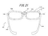
- FIG. 21 is a rear perspective view showing a schematic configuration of the glasses-type display device of the fourth reference example.
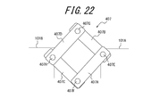
- FIG. 22 is an enlarged view (top view) illustrating the bridge adjustment unit 407 of the glasses-type display device 400 according to the fourth reference example.
- the structure of the bridge adjustment unit 407 is different from that of the glasses-type display device 100 according to the first reference example.
- the other configuration is the same as that of the first reference example.
- the bridge adjustment unit 407 according to the present reference example includes four support portions 407A, 407B, 407C, and 407D, and four fixing portions 407E, 407F, 407G, and 407H serving as pivot axes of the support portions.
- One end of the supporting portion 407A is rotatably fixed to the spectacles lens portion 101A together with one end of the supporting portion 407B by the fixing portion 407E, and the other end is rotatably fixed to one end of the supporting portion 407C by the fixing portion 407F.
- the other end of the support portion 407C is rotatably fixed to the spectacle lens portion 101B together with one end portion of the support portion 407D by the fixing portion 407H.
- the other end of the support portion 407D is rotatably fixed to the other end of the support portion 407B by a fixing portion 407G.
- the bridge adjustment unit 407 rotates the four fixing portions 407E, 407F, 407G, and 407H because the fixing portion 407E is fixed to the supporting portions 407A and 407B to the eyeglass lens portion 101A and the fixing portion 407H to the eyeglass lens portion 101B.
- the relative position between the spectacle lens unit 101A and the spectacle lens unit 101B can be adjusted by moving the four support units 407A, 407B, 407C, and 407D around the movement axis. In other words, the distance between the spectacle lens unit 101A and the spectacle lens unit 101B can be adjusted. In this way, it is possible to adjust the eye point corresponding to the individual difference of the user.
- FIG. 23 is a top view for explaining the bridge adjustment unit 507 of the glasses-type display device 500 according to the fifth reference example.
- FIG. 24 is an enlarged view of the bridge adjustment unit 507 of the glasses-type display device 500 of the fifth reference example.
- the structure of the bridge adjustment unit 507 is different from that of the glasses-type display device 100 according to the first reference example.
- the other configuration is the same as that of the first reference example.
- the bridge adjusting portion 507 includes a rim extension portion 507A extending from the rim portion 103A, a rim extension portion 507B extending from the rim portion 103B, one end of the rim extension portion 507A and the rim extension And a fixing portion 507C rotatably fixing one end of the portion 507B.
- the bridge adjusting unit 507 can adjust the angle ⁇ between the eyeglass lens portion 101A and the eyeglass lens portion 101B by rotating the eyeglass lens portion 101A and the eyeglass lens portion 101B about the fixing portion 507C as a rotation axis.
- the angle formed by the eyeglass lens portion 101A and the eyeglass lens portion 101B as compared with the case where the user of eye width L2 wears the eyeglass-type display devices 500.
- the eyeglass lens unit 101A and the eyeglass lens unit 101B are rotated so as to reduce ⁇ .
- the bridge adjustment unit 507 can adjust the angle ⁇ formed by the spectacle lens unit 101A and the spectacle lens unit 101B, and as a result, the eye point is adjusted to the eye width L1. It is possible to adjust to the position according to the eye width L2 from the above position.
- FIG. 25 (a) and 25 (b) are enlarged views for explaining a modification of the glasses-type display device 500 of the fifth reference example.
- the glasses-type display device 500 of the fifth reference example is different from the glasses-type display device 500 in that a temple angle adjustment member 508 disposed between the spectacle lens unit 101 and the temple unit 104 is provided.
- FIG. 25 (a) is an enlarged view of the hinge portion 106A when the glasses-type display device 500 is not provided with the temple angle adjustment member 508, and
- FIG. 25 (b) is a glasses-type display device 500 including the temple angle adjustment member 508. It is an enlarged view of hinge part 106A in the case of having.
- FIG. 25 (a) is an enlarged view of hinge portion 106A when the glasses-type display device 500 is not provided with the temple angle adjustment member 508, and
- FIG. 25 (b) is a glasses-type display device 500 including the temple angle adjustment member 508. It is an enlarged view of hinge part 106A in the case of having.
- the bridge adjustment unit 507 can adjust the angle formed by the left and right eyeglass lens units 101A and 101B. At this time, if the angle between the left and right eyeglass lens parts 101A and 101B is reduced, the distance between the left and right temple parts 104A and 104B fixed to the head of the user is narrowed. On the other hand, when the angle between the left and right eyeglass lens portions 101A and 101B is increased, the distance between the left and right temple portions 104A and 104B fixed to the head of the user is also increased.
- the temple angle adjustment member 508 is attached so as to be sandwiched between the spectacle lens unit 101 and the temple unit 104.
- the distance between the temple portions 104A and 104B is reduced by attaching between the left and right eyeglass lens portions and the temple portions.
- the user can adjust the angle between the left and right eyeglass lens units 101A and 101B to be large by the bridge adjustment unit 107 without increasing the distance between the left and right temples 104A and 104B. That is, the bridge adjustment unit 107 can adjust the eye width, and the temple angle adjustment member 508A can adjust the head size. In other words, the angle formed between the spectacle lens portion 101A and the temple portion 104A can be adjusted by the temple angle adjustment member 508A.
- the temple angle adjustment member 508 is a separate member, it may be another configuration.
- a hole may be formed on the side of the temple portion 104A in contact with the spectacle lens portion 101A, and an extension member (temple angle adjustment member) slidably fixed to the hole may be provided.
- the angle between the spectacle lens portion 101A and the temple portion 104A can be adjusted in a state in which the extension member is accommodated in the hole and in a state in which the extension member is arranged outside the hole.
- it may be a member that regulates the rotation angle of the hinge portion 106A.
- the reference example may be a spectacles type display device which does not have a rim portion for holding a spectacle lens (rimless). In this case, it goes without saying that the bridge adjustment unit adjusts the relative position between the spectacle lenses.
- it may be a glasses-type display device in which the spectacle lens portion does not have a spectacle lens and only the rim portion is made. In this case, it goes without saying that the bridge adjustment unit adjusts the relative position between the rims.
- the display device image display unit
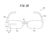
- FIG. 26 the display device (image display unit) may be disposed in front of the spectacle lens.
- the display device image display unit
- the display device may be disposed so that the longitudinal direction of the eyepiece optical unit is not a substantially horizontal direction but a vertical direction. Even when arranged as shown in FIGS. 26 and 27, the effect of the present invention does not change. Furthermore, it is also possible to combine the above reference examples.
Landscapes
- Physics & Mathematics (AREA)
- General Physics & Mathematics (AREA)
- Optics & Photonics (AREA)
- Health & Medical Sciences (AREA)
- Ophthalmology & Optometry (AREA)
- Engineering & Computer Science (AREA)
- Multimedia (AREA)
- Signal Processing (AREA)
Abstract
本発明の眼鏡型表示装置10は、使用者の眼前に配置される眼鏡フロント部12と、眼鏡フロント部12に接続され、使用者の頭部に装着される左右のテンプル部11と、眼鏡フロント部12を左右のテンプル部11に対して回動することにより、眼鏡フロント部12の傾きを調整する接続部17と、眼鏡フロント部12に対して固定され、使用者の眼球に画像光を投影する画像表示部22とを備え、接続部17は、回動の中心軸が側面視において使用者の眼球中心よりも前記眼鏡フロント部12側に位置することを特徴とする。
Description
本発明は、頭部に装着する眼鏡型表示装置に関するものである。
近年、眼鏡型のフレームに小型の表示装置を組み込み、使用者の視野内に画像を投影する眼鏡型表示装置の開発が進められている(例えば、特許文献1~3参照)。例えば、特許文献1に記載の眼鏡型表示装置では、眼鏡フレームの下側リムに画像を投影するための接眼レンズが設けられ、使用者が視線を接眼レンズに向けた時のみ画像を観察できるようになっている。眼鏡型表示装置は、煩雑な装着機構を必要とせず、一般的な眼鏡をかけるのと同様に表示装置を使用者の頭部に装着することができる。
しかし、眼鏡型表示装置では、使用者の眼球に画像を投影するために、ヘルメット型やゴーグル型などの頭部装着型表示装置とは異なり、使用者の周辺視野を妨げない小型の画像表示部が使用される。このような小型の画像表示部を用いると、使用者が画像を良好に視認可能な領域(アイボックス)は、必然的に狭くなる。このため、典型的な眼鏡型表示装置では、眼鏡の位置が僅か数mmずれただけでも、画像が視認しにくくなる。一方、使用者には頭部の大きさ、鼻、耳等の位置や形状の違い等の面で個人差がある。このため、眼鏡型画像表示装置では、個人差に応じて、使用者の眼の位置が画像を視認することが可能な領域に入るように、精度よくアライメント調整(以下単に位置調整と呼ぶ)をする調整機構が必要になる。
例えば、引用文献2に記載の眼鏡型画像表示装置では、表示部が設けられた眼鏡フレームの正面部分(眼鏡フロント部)を、側面視において眼球中心に回動軸をおいて回転調整可能に構成し、眼球に対する画像の入射角度を調整することができる。また、引用文献3に記載の眼鏡型画像表示装置では、使用者により鼻当ての位置を調整することができるように、位置調整部を設けている。
しかしながら、眼鏡フロント部を、側面視における眼球中心を回動中心として回動させる調整機構では、画像の見える位置を上下に動かすことはできるものの、アライメント調整を行うことはできない。また、眼鏡フロント部全体が眼鏡テンプル部の延びる方向に対して大きくずれて傾き、外観上の違和感が生じる。さらに、眼鏡フロント部を回動させる調整によって鼻当てと鼻の位置関係もずれるので、眼鏡フロント部の眼鏡テンプル部に対する傾きの状態によっては、鼻当てが鼻に当接しなくなる。このため、眼鏡型画像表示装置の使用者の頭部に対する装着状態が不安定になり、位置決めの精度が低下することが懸念される。また、従来技術における鼻当ての位置調整は、使用者の装着感を調整することを主な目的とし、表示画像位置と装着感の双方を同時に調整することはできない。
したがって、これらの点に着目してなされた本発明の目的は、使用者の眼の位置に対して表示画像の調整を精度よく行うことができる眼鏡型表示装置を提供することにある。
上記目的を達成する眼鏡表示装置の発明は、
使用者の眼前に配置される眼鏡フロント部と、
前記眼鏡フロント部に接続され、使用者の頭部に装着される左右のテンプル部と、
前記眼鏡フロント部を前記左右のテンプル部に対して回動することにより、前記眼鏡フロント部の傾きを調整する角度調整部と、
前記眼鏡フロント部に対して固定され、使用者の眼球に画像光を投影する画像表示部と
を備え、前記角度調整部は、回動の中心軸が側面視において使用者の眼球中心よりも前記眼鏡フロント部側に位置することを特徴とするものである。
使用者の眼前に配置される眼鏡フロント部と、
前記眼鏡フロント部に接続され、使用者の頭部に装着される左右のテンプル部と、
前記眼鏡フロント部を前記左右のテンプル部に対して回動することにより、前記眼鏡フロント部の傾きを調整する角度調整部と、
前記眼鏡フロント部に対して固定され、使用者の眼球に画像光を投影する画像表示部と
を備え、前記角度調整部は、回動の中心軸が側面視において使用者の眼球中心よりも前記眼鏡フロント部側に位置することを特徴とするものである。
前記眼鏡フロント部はリム部を備え、前記画像表示部は前記リム部の使用者側の面に配置されていることが好ましい。
また、前記角度調整部の前記回動の中心軸は、側面視において前記画像表示部の近傍に位置することが好ましい。
さらに、前記左右のテンプル部は、伸縮可能に構成することができる。
また、前記画像表示装置は、使用者の鼻に当接する鼻当てと、該鼻当ての前記眼鏡フロント部に対する高さ位置を調整する高さ位置調整機構とを備えることができる。
なお、眼鏡フロント部とは、眼鏡の正面部分を意味し、眼鏡の正面側のフレームおよび/またはレンズ等を含む。画像表示部の近傍とは、画像表示部の画像光射出部分からの距離が12mm以内を意味する。
本発明によれば、眼鏡フロント部を左右のテンプル部に対して回動することにより、眼鏡フロント部の傾きを調整する角度調整部を備え、該角度調整部は、回動の中心軸が側面視において使用者の眼球中心よりも前記眼鏡フロント部側に位置するので、使用者の眼の位置に対して表示画像の調整、特に垂直方向の位置調整を精度よく行うことができる。
以下、本発明の実施の形態について、図面を参照して説明する。
<第1実施の形態>
図1は、本発明の第1実施の形態に係る眼鏡型表示装置10の斜視図であって、眼鏡の背面側から見た図である。眼鏡型表示装置10は、左右のテンプル部11と眼鏡フロント部12とを含んで構成される眼鏡部分と、画像表示部20とを備える。テンプル部11は、通常の眼鏡と同様に、使用者の耳に掛けて眼鏡型表示装置10を装着するためのものである。眼鏡フロント部12は、使用者の眼前に配置される眼鏡の正面部分であり、左右のリム部13、ブリッジ部14、左右のレンズ15および左右の鼻当て16を含んでいる。左右のリム部13は、それぞれ左右のレンズ15の周りを囲むようにして、これを保持している。またブリッジ部14は、左右のレンズ15を囲む左右のリム部13の中央に位置し、これらを接続している。また、鼻当て16は、左右のリム部13の、使用者の鼻に当接する部分に設けられている。なお、以下において、眼鏡型表示装置10の装着時に、正面に向いた側を正面側、使用者の顔に面した側を背面側と呼ぶ。また、上、下、右、左、水平、垂直等は、使用者が眼鏡型表示装置10を装着した状態での方向を示すものとする。
図1は、本発明の第1実施の形態に係る眼鏡型表示装置10の斜視図であって、眼鏡の背面側から見た図である。眼鏡型表示装置10は、左右のテンプル部11と眼鏡フロント部12とを含んで構成される眼鏡部分と、画像表示部20とを備える。テンプル部11は、通常の眼鏡と同様に、使用者の耳に掛けて眼鏡型表示装置10を装着するためのものである。眼鏡フロント部12は、使用者の眼前に配置される眼鏡の正面部分であり、左右のリム部13、ブリッジ部14、左右のレンズ15および左右の鼻当て16を含んでいる。左右のリム部13は、それぞれ左右のレンズ15の周りを囲むようにして、これを保持している。またブリッジ部14は、左右のレンズ15を囲む左右のリム部13の中央に位置し、これらを接続している。また、鼻当て16は、左右のリム部13の、使用者の鼻に当接する部分に設けられている。なお、以下において、眼鏡型表示装置10の装着時に、正面に向いた側を正面側、使用者の顔に面した側を背面側と呼ぶ。また、上、下、右、左、水平、垂直等は、使用者が眼鏡型表示装置10を装着した状態での方向を示すものとする。
一方のレンズ15(図では右側レンズ)の上側のリム部13には、画像表示部20が設けられる。画像表示部20は、リム部13と一体に形成することができる。この画像表示部20には、図示しないLCDや有機ELなどの表示素子が内蔵され、固定されている。画像表示部20は、この表示素子の画像の画像光を内部の光学系によって導光し、一方のレンズ15の中央部上側に配置された接眼レンズ等により構成される接眼光学部22から、使用者の眼球に向けて投影する。これによって、使用者は、表示素子に表示される画像を虚像として観察することができる。画像表示部20は、正面からは見えないようにリム部13の背面側に配置される。これによって、眼鏡型表示装置10は、装着時に通常の眼鏡とほぼ区別のつかない外観を有する。
画像表示部20内の表示素子に表示される画像のデータは、テンプル部11に装着された信号処理部21から、フレキシブル配線(図示せず)を介して供給される。もちろん、画像データの送信はこれに限られず、使用者の有する携帯電話などの携帯情報端末から、画像表示部20に有線または無線の通信手段により送信するようにしても良い。その場合、信号処理部21を配置する必要はない。
次に、眼鏡フロント部12のリム部13と左右のテンプル部11との接続形態について説明する。リム部13とテンプル部11とは、接続部17で接続されている。図2は、この接続部17の構成を説明する図であり、(a)は上面図、(b)は装着時に使用者に接する側から見た側面図となっている。リム部13とテンプル部11との間は、中間部材25を介して接続されている。中間部材25とリム部13との間は、通常の眼鏡におけるリム部とテンプル部の接続のように、ヒンジ軸26を有するヒンジによって接続されている。このヒンジ軸26は上下方向に延び、眼鏡型表示装置10のテンプル部11を水平方向に折り畳むことを可能にする。ヒンジ軸26は、後述する回動軸27よりも後ろ側に設けることによって、折り畳み時にテンプル部11と眼鏡フロント部12とが干渉し難く、折り畳みしやすい構造となっている。
一方、リム部13と中間部材25との間の接続は、テンプル部11に対して眼鏡フロント部12を傾動可能に構成されている。具体的には、以下である。リム部13の中間部材25側端部は、使用者側に面する面に、外形が半円状の弧を有する所定の厚さの切り欠きが形成されている。これに対して、中間部材25のリム部13側端部は、上記リム部13の切り欠き部分と略同じ半径の円弧を有する板状部分を有し、リム部13の切り欠き部に、円弧部分を摺動可能に嵌めこまれている。また、中間部材25は、上記円弧の中心をリム部13に対してピンなどの回動軸27(回動の中心軸)によって軸支されている。回動軸27は、水平方向に延びているので、中間部材25に対して、リム部13は垂直方向に回動可能に支持される。なお、リム部13と中間部材25との間は、適度な摩擦力等によって相互に姿勢が保持される。このように、リム部13と中間部材25との接続部分は、角度調整部を構成する。
図3は、図1の眼鏡型表示装置10を使用者に装着した状態を示す図である。使用者は、テンプル部11の後ろ側を耳32に掛け、眼鏡フロント部12の鼻当て(図3において図示せず)を鼻33に当接させた状態で眼鏡型表示装置10を装着する。このとき、回動軸27は、使用者の眼球中心Oよりも眼鏡フロント部12側に位置する。特に好ましくは、回動軸27は、側面視において接眼光学部22の近傍に位置する。なお、接眼光学部22の近傍とは、側面視において接眼光学部22からの距離が12mm以内を意味する。一般に、眼鏡のレンズと眼球31との距離は12mm程度であり、また、ヒトの眼球の半径も12mm程度である。角度調整部の回動軸27が、側面視において眼球中心Oと一致してしまうと、眼鏡フロント部12を回動させても、接眼光学部から射出される画像光の光軸に沿った光線(以下、単に射出光線)が眼球中心Oを通ることはなく、アライメント調整はできない。一方、回動軸27と接眼光学部22との距離が、レンズから眼球中心Oまでの距離である24mmの半分の12mmより小さければ、回動による位置調整の効果が大きいと考えられる。
次に、眼鏡型表示装置10を用いた表示画像の観察について説明する。図4は、正面視の時の眼鏡フロント部12と眼球31との位置及び向きの関係を説明する図である。また、図5は、表示画像視認時の眼鏡フロント部12と眼球31との位置及び向きの関係を説明する図である。使用者は、図4のように、眼鏡型表示装置10の装着時において、通常はレンズ15を通して眼前の風景や目標物を見る。この時の、使用者の視軸Aを図4に示す。これに対して、使用者が眼鏡型表示装置10の画像を見る場合は、図5に示すように、眼球31を上方へ回転させて接眼光学部22に視軸Aを向ける。これにより、使用者は眼鏡型表示装置10により投影される画像を視認することができる。このとき見上げる角度は15~30°、好ましくは25度程度がよい。
ここで、画像表示部20内の表示素子から射出される画像光は、リム部13に沿って画像表示部20内の光学系を導光されて、小型の接眼光学部22から射出される。このため、使用者が良好に画像を観察できるアイボックスは比較的狭い範囲に限定される。このため、眼鏡型表示装置10は使用者の眼球31に対して位置調整ができることが重要になる。図6および図7は、眼鏡型表示装置10と眼球31との位置調整が外れた状態の例を示す図である。図6では、接眼光学部22から射出され、使用者の眼球31の瞳孔を通過した射出光線Lが、眼球中心Oの下側を通っている。この場合は、使用者の視界には、上側が欠けた画像が投影される。また、図7では、接眼光学部22から射出され、使用者の眼球31の瞳孔を通過した射出光線Lが、眼球中心Oの上側を通っている。この場合は、使用者の視界には、下側が欠けた画像が投影される。
そこで、眼鏡フロント部12をテンプル部11に対して回動させることによって、眼鏡型表示装置10の傾きを変化させる位置調整を行う。図8は、眼鏡フロント部12を回動させることによる位置調整を説明する図である。眼鏡フロント部12を回動させ、接眼光学部22から射出される射出光線Lの方向を眼球31の眼球中心Oを通る方向とすることによって、使用者が眼球31を回転させて視軸Aを接眼光学部22に向け、接眼光学部22からの表示画像を視認することが可能になる。
以上説明したように、本実施の形態によれば、眼鏡フロント部12を左右のテンプル部11に対して回動することにより、眼鏡フロント部12の傾きを調整する角度調整部を設け、角度調整部は、傾きを調整する回動軸27が側面視において使用者の眼球中心Oよりも眼鏡フロント部12側に位置するので、使用者の眼の位置に対して表示画像を良好に視認できるように位置調整を精度よく行うことができる。また、接眼光学部22はリム部13の使用者側の面に配置されているので、正面から見たときにリム部13の背面側に隠れる。このため、外観上通常の眼鏡と区別がつかず、他人から見たときの違和感がない。さらに、前記角度調整部の前記回動の中心軸は、側面視において接眼光学部22の近傍に位置するので、眼鏡フロント部12を僅かに動かすだけで、その傾きを大きく調整することができる。
<第2実施の形態>
なお、上記第1実施の形態では、眼鏡フロント部12をテンプル部11に対して回動させることのみによって、接眼光学部22の位置調整を行った。一方、図6および図7を再び参照すると、接眼光学部22の向きを変えずに前後または上下に移動させることによっても、表示画像の視認状態を改善することができる。例えば、図6において接眼光学部22の向きを変えずに眼球31側に水平に移動させることによって、射出光線Lが眼球中心Oを通るようにすることができる。あるいは、接眼光学部22の向きを変えずに、上方へずらすことによっても、射出光線Lが眼球中心Oを通るようにすることができる。第2実施の形態では、接眼光学部22の水平方向の移動および/または上下方向の位置調整と、回動軸27回りの回動を組み合わせて表示画像の調整を行うものである。
なお、上記第1実施の形態では、眼鏡フロント部12をテンプル部11に対して回動させることのみによって、接眼光学部22の位置調整を行った。一方、図6および図7を再び参照すると、接眼光学部22の向きを変えずに前後または上下に移動させることによっても、表示画像の視認状態を改善することができる。例えば、図6において接眼光学部22の向きを変えずに眼球31側に水平に移動させることによって、射出光線Lが眼球中心Oを通るようにすることができる。あるいは、接眼光学部22の向きを変えずに、上方へずらすことによっても、射出光線Lが眼球中心Oを通るようにすることができる。第2実施の形態では、接眼光学部22の水平方向の移動および/または上下方向の位置調整と、回動軸27回りの回動を組み合わせて表示画像の調整を行うものである。
図9は、第2実施の形態に係る眼鏡型表示装置10Aを使用者に装着した状態を示す図である。この眼鏡型表示装置10Aは、第1実施の形態に係る眼鏡型表示装置10とテンプル部41が異なっている。テンプル部41は、眼鏡フロント部12側の第1部分41aと、その後ろ側に位置する耳かけ部分を含む第2部分41bとから構成されている。第1部分41aの後ろ側部分は、テンプル部41の長手方向に沿う空洞が設けられている。すなわち、第1部分41aの後ろ側部分は、鞘状となっている。これに対して、第2部分41bの前側部分は、外形が第1部分41aの空洞部分よりも僅かに小さく、第1部分41aの内部で摺動可能に構成されている。ただし、第2部分41bは第1部分41aから離脱しないようになっている。これにより、テンプル部41は全体として伸縮可能に構成されている。なお、テンプル部41を伸縮させた後、第1部分41aと第2部分41bとの位置関係が変化しないように、相互に固定する機構を設けても良い。その他の構成は、第1実施の形態と同様であるので、同一構成要素には同一参照符号を付して説明を省略する。
以上のような構成により、第2実施の形態に係る眼鏡型表示装置10Aは、必要に応じてテンプル部41を伸縮させ、眼鏡フロント部12と眼球31との距離を調整することができる。例えば、接眼光学部22の射出光線が眼球中心Oの上側を通過し、使用者が視認する画像の下側が欠けるような場合は、テンプル部41を伸ばして眼鏡フロント部12を遠ざけて、射出光線が眼球中心Oを通るように調整する。これによって、表示画像が良好に視認できるように位置調整することができる。また、テンプル部41を伸縮することによって、良好な装着感と画像が得られる位置に眼鏡型表示装置10Aを調整したうえで、最終的な表示画像の視認状態の微調整を、眼鏡フロント部12の傾きの調整により行うことが可能である。
<第3実施の形態>
図10は、第3実施の形態に係る眼鏡型表示装置10Bを使用者に装着した状態を示す図である。この眼鏡型表示装置10Bもまた、第1実施の形態に係る眼鏡型表示装置10とはテンプル部42が異なっている。テンプル部42は、眼鏡フロント部12側から順に、第1部分42a、第2部分42bおよび第3部分42cから構成されている。第1部分42aと第2部分42bとの間は、第1回動軸43aが設けられ、互いにこの第1回動軸43aの周りに所定の範囲で回動可能に接続されている。また、第2部分42bと第3部分42cとの間は、第2回動軸43bが設けられ、互いにこの第2回動軸43bの周りに所定の範囲で回動可能に接続されている。その他の構成は、第1実施の形態と同様であるので、同一構成要素には同一参照符号を付して説明を省略する。
図10は、第3実施の形態に係る眼鏡型表示装置10Bを使用者に装着した状態を示す図である。この眼鏡型表示装置10Bもまた、第1実施の形態に係る眼鏡型表示装置10とはテンプル部42が異なっている。テンプル部42は、眼鏡フロント部12側から順に、第1部分42a、第2部分42bおよび第3部分42cから構成されている。第1部分42aと第2部分42bとの間は、第1回動軸43aが設けられ、互いにこの第1回動軸43aの周りに所定の範囲で回動可能に接続されている。また、第2部分42bと第3部分42cとの間は、第2回動軸43bが設けられ、互いにこの第2回動軸43bの周りに所定の範囲で回動可能に接続されている。その他の構成は、第1実施の形態と同様であるので、同一構成要素には同一参照符号を付して説明を省略する。
以上のような構成により、眼鏡型表示装置10Bは、使用者の耳32の高さ位置が異なるような場合でも、テンプル部42の第3部分42cの高さを調整して耳かけ部分の高さを調整することができる。これにより、誰にでも同様な装着感を提供するとともに、第1実施の形態と同様に眼鏡フロント部12の傾きの調整を行うことができる。なお、本実施の形態では、テンプル部42の第1部分42a、第2部分42bおよび第3部分42cの相互の傾きを調整することによって、例えば、第1部分42aの後ろ側端部を押し下げるまたは押し上げることができる。これによっても、眼鏡フロント部12の傾きの調整が可能になる。
<第4実施の形態>
図11は、第4実施の形態に係る眼鏡型表示装置10Cを使用者に装着した状態を示す図である。この眼鏡型表示装置10Cのテンプル部44は、第1部分44a及び第2部分44bを備え、第1部分44aと第2部分44bとの間は、回動軸45により所定範囲内で回動可能に接続されている。その他の構成は、第1実施の形態と同様であるので、同一構成要素には同一参照符号を付して説明を省略する。第4実施の形態に係る眼鏡型表示装置10Cは、第3実施の形態に係る眼鏡型表示装置10Bと比べて、より単純な構成でありながら、使用者の耳32の高さ位置に対する調整を可能にしたものである。
図11は、第4実施の形態に係る眼鏡型表示装置10Cを使用者に装着した状態を示す図である。この眼鏡型表示装置10Cのテンプル部44は、第1部分44a及び第2部分44bを備え、第1部分44aと第2部分44bとの間は、回動軸45により所定範囲内で回動可能に接続されている。その他の構成は、第1実施の形態と同様であるので、同一構成要素には同一参照符号を付して説明を省略する。第4実施の形態に係る眼鏡型表示装置10Cは、第3実施の形態に係る眼鏡型表示装置10Bと比べて、より単純な構成でありながら、使用者の耳32の高さ位置に対する調整を可能にしたものである。
<第5実施の形態>
第5実施の形態に係る眼鏡型表示装置は、上記第2実施の形態に係る眼鏡型表示装置10Aの構成に加え、鼻当て16の高さ位置の調整機構を設けたものである。図12は、第5実施の形態に係る眼鏡型表示装置の鼻当て16の高さ位置調整機構を説明する図である。この図は、鼻当て16を鼻に当接する部分の反対側から見た斜視図である。鼻当て16は、スライドパーツ46と鼻パッド47により構成される。スライドパーツ46は、パッドアーム48を介して、リム部13の鼻側に面した部分に接続される。鼻パッド47には、スライド溝49が設けられる。スライド溝49は、該スライド溝49の長手方向に延びる両側面49a,49bに沿って波状の凹凸が多数形成され、両側面間の間隔が長手方向に周期的に変化する構造となっている。スライドパーツ46には、このスライド溝49内で、スライド溝49の側面49a,49bの凹部に対して付勢されて当接する板バネ(弾性部材)が固定されている。スライドパーツ46は、板バネがスライド溝49から離脱しないように、スライド溝49に沿って摺動するように構成される。使用者が、この鼻パッド47に手をかけて、上下に力を加えることにより、板バネが弾性力に抗して側面49a,49bの凹部を脱出して隣接する凹部へ異動する。このようにして、使用者は鼻当て16を上下に移動させ、高さ位置を調整することができる。なお、図12は、左側の鼻当て16の高さ位置調整機構を示しているが、右側の鼻当て16も同様の高さ位置調整機構を有する。
第5実施の形態に係る眼鏡型表示装置は、上記第2実施の形態に係る眼鏡型表示装置10Aの構成に加え、鼻当て16の高さ位置の調整機構を設けたものである。図12は、第5実施の形態に係る眼鏡型表示装置の鼻当て16の高さ位置調整機構を説明する図である。この図は、鼻当て16を鼻に当接する部分の反対側から見た斜視図である。鼻当て16は、スライドパーツ46と鼻パッド47により構成される。スライドパーツ46は、パッドアーム48を介して、リム部13の鼻側に面した部分に接続される。鼻パッド47には、スライド溝49が設けられる。スライド溝49は、該スライド溝49の長手方向に延びる両側面49a,49bに沿って波状の凹凸が多数形成され、両側面間の間隔が長手方向に周期的に変化する構造となっている。スライドパーツ46には、このスライド溝49内で、スライド溝49の側面49a,49bの凹部に対して付勢されて当接する板バネ(弾性部材)が固定されている。スライドパーツ46は、板バネがスライド溝49から離脱しないように、スライド溝49に沿って摺動するように構成される。使用者が、この鼻パッド47に手をかけて、上下に力を加えることにより、板バネが弾性力に抗して側面49a,49bの凹部を脱出して隣接する凹部へ異動する。このようにして、使用者は鼻当て16を上下に移動させ、高さ位置を調整することができる。なお、図12は、左側の鼻当て16の高さ位置調整機構を示しているが、右側の鼻当て16も同様の高さ位置調整機構を有する。
第2実施の形態の眼鏡型表示装置においては、テンプル部41を伸縮させると、使用者の鼻33と眼鏡フロント部12の鼻当て16の当接位置がずれてしまう。例えば、テンプル部41を伸長させた場合は、眼鏡フロント部12が前方へつき出るため、鼻当て16は鼻33に当接するためには下に下がることになる。そこで、本実施の形態では、高さ位置調整機構を用いて、鼻当て16を眼鏡フロント部12に対して上下方向に位置調整する。高さ位置調整機構を設けたことによって、使用者の眼鏡型表示装置の装着感を好適な状態に調整しながら、良好な画像が得られるように眼鏡フロント部12の傾きおよび位置を調整することができる。
本実施の形態に係る眼鏡型表示装置を用いた場合の調整方法としては、まず、テンプル部41の長さを決定し、テンプル部41の長さに応じて鼻当て16の高さ位置調整を調整する。これによって、良好な画像が観察できるようにする。このとき、鼻当て16の鼻への当たりや、レンズ15と眼球31との距離は、眼鏡型表示装置の装着感に影響を与える。このため、これらの調整においては、画像の表示状況以上に装着感の良さを重視した位置調整を行う。テンプル部41の長さと鼻当て16の高さが決定したら、次に、眼鏡フロント部12を回動軸27回りに回動させる調整を行い、最も良好な画像が視認できる位置に固定する。これによって、眼鏡型表示装置を最も良好な状態に調整することが可能になる。また、本実施の形態の高さ位置調整機構は、鼻パッド47に設けた溝に対してスライドパーツ46をスライドさせるものなので、小型で且つ正面から見たときにリム部13に隠れて外観上目立たないという利点も有している。
なお、本発明は、上記実施の形態にのみ限定されるものではなく、幾多の変形または変更が可能である。たとえば、レンズは、度が入っていても入っていなくても良く、また、使用者が必要としない場合は、レンズは無くても良く、その場合の眼鏡フロント部は、主にフレームにより構成される。また、中間部材を直接レンズに接続すれば、リム部は無くても良い。その場合レンズ上に沿って直接画像表示部が設けられる。画像表示部は、右側および左側の何れの眼側に設けても良く、あるいは、両方の眼に対応して合計2つの画像表示部を設けても良い。また、画像表示部はレンズの上側のリムに重ねる構成に限られず、正面から見た時下側のリムに重なるように配置しても良い。あるいは、リムやレンズに近接する任意の位置に配置することもできる。さらに、眼鏡フロント部をテンプル部に対して回動させる機構は、例示のもの以外に種々の方法が可能である。
次に、本発明の参考例について説明する。これらの参考例は、眼鏡型表示装置において、左右の眼鏡レンズ部の相対的な位置を調整するブリッジ調整部により、使用者の個人差に応じたアイポイントの調整を行うものである。
<第1参考例>
図13は、第1参考例にかかる眼鏡型表示装置100の概略構成を示す前方斜視図である。図14は、第1参考例にかかる眼鏡型表示装置100の概略構成を示す後方斜視図である。本参考例にかかる眼鏡型表示装置100は、使用者の左右の眼の前に配置される眼鏡レンズ部101A、101Bと、眼鏡レンズ部に接続され、使用者の頭部に装着されるテンプル部104A、104Bと、眼鏡レンズ部101A及び101Bの間に介在するブリッジ部105と、テンプル部104A、104Bを眼鏡レンズ部101A、101Bに対して折りたたみ可能に連結するヒンジ部106A、106Bと、使用者に画像を表示する表示装置(画像表示部)110とを備える。
図13は、第1参考例にかかる眼鏡型表示装置100の概略構成を示す前方斜視図である。図14は、第1参考例にかかる眼鏡型表示装置100の概略構成を示す後方斜視図である。本参考例にかかる眼鏡型表示装置100は、使用者の左右の眼の前に配置される眼鏡レンズ部101A、101Bと、眼鏡レンズ部に接続され、使用者の頭部に装着されるテンプル部104A、104Bと、眼鏡レンズ部101A及び101Bの間に介在するブリッジ部105と、テンプル部104A、104Bを眼鏡レンズ部101A、101Bに対して折りたたみ可能に連結するヒンジ部106A、106Bと、使用者に画像を表示する表示装置(画像表示部)110とを備える。
眼鏡レンズ部101Aは、使用者の右眼前方に配置され、眼鏡レンズ102Aと、眼鏡レンズ102Aを保持するリム部103Aとからなる。同様に、眼鏡レンズ部101Bは、使用者の左眼前方に配置され、眼鏡レンズ102Bと、眼鏡レンズ102Bを保持するリム部103Bとからなる。
なお、眼鏡レンズ部101A、101Bは、眼鏡レンズとリム部を両方備える構成に限らず、眼鏡レンズとリム部のどちらか一方のみでもあってもよい。例えば、眼鏡レンズを保持するリム部を有さない(リムレス)の眼鏡型表示装置であってもよい。また、眼鏡レンズを有さず、眼鏡レンズ部がリム部のみからなる眼鏡型表示装置であってもよい。
なお、眼鏡レンズ部101A、101Bは、眼鏡レンズとリム部を両方備える構成に限らず、眼鏡レンズとリム部のどちらか一方のみでもあってもよい。例えば、眼鏡レンズを保持するリム部を有さない(リムレス)の眼鏡型表示装置であってもよい。また、眼鏡レンズを有さず、眼鏡レンズ部がリム部のみからなる眼鏡型表示装置であってもよい。
表示装置(画像表示部)110は、表示素子を有する本体部111と表示素子からの画像光を使用者の眼球E1に投影する接眼光学部112とを備える。本体部111は、リム部103Aの使用者側の側面に配置される。接眼光学部112は、リム部103Aの使用者側の側面にリム部103Aに沿うように配置される。このように眼鏡型表示装置100は、表示装置110がリム部103Aの使用者側の側面に配置されているため、外観を損なうことのないウェアラブル機器となる。なお、表示素子に電源を供給するバッテリ等は、リム部103Aやテンプル部104Aに内蔵する構成でもよいし、有線にて外部機器から供給される構成であってもよい。
図15は、第1参考例の眼鏡型表示装置100のブリッジ調整部107を説明する上面図である。図15では、眼幅L1の使用者が眼鏡型表示装置100を装着した場合と、眼幅L1より長い眼幅L2の使用者が眼鏡型表示装置100を装着した場合を示す。ブリッジ部105は、スライド軸107Aと、スライド軸107Aを固定するスライド軸固定部107B、107Cとからなるブリッジ調整部107を備える。スライド軸固定部107B、107Cは、リム部103A、103Bにそれぞれ固定されている。さらにスライド軸固定部107B、107Cは、それぞれ孔を有する。スライド軸107Aは、その両端がスライド軸固定部107B、107Cの孔に挿入され、固定される。
ブリッジ調整部107は、スライド軸107Aに沿ってスライド軸固定部107B、107Cを動かすことで、眼幅L1の使用者、眼幅L2の使用者のそれぞれに対応したアイポイントの調整を行なうことができる。眼幅L2の使用者が眼鏡型表示装置100を装着した場合、眼幅L1の使用者が眼鏡型表示装置100を装着した場合に比べて、スライド軸固定部107Bと107Cとの距離が長くなるようにスライド軸固定部107B、107Cをスライド軸107Aに沿って移動させる。スライド軸固定部107B、107Cはリム部103A、103Bに固定されているため、スライド軸固定部107B、107Cを両者の距離が長くなるように移動させることで、リム部103Aと103Bとの距離も長くなる。言い換えると、左右のリム部103A、103Bの相対的位置が調整される。画像光を使用者の眼球に投影する接眼光学部112はリム部103Aの使用者側の側面に配置されていることから、リム部103A、103B間の距離が長くなると、接眼光学部112もリム部103Aに伴って移動する。このようにして本参考例の眼鏡型表示装置100は、ブリッジ調整部107によってアイポイントを眼幅L1に応じた位置から眼幅L2に応じた位置に調整することができる。また本参考例の眼鏡型表示装置100は、簡易な構成でアイポイントの調整が可能であり、外観上も一般的な眼鏡と変わらず、外観を損なうことがない。
<第2参考例>
次に第2参考例の眼鏡型表示装置200について説明する。図16は、第2参考例にかかる眼鏡型表示装置200のブリッジ調整部207を説明する上面図である。図16では、眼幅L1の使用者が眼鏡型表示装置200を装着した場合と、眼幅L1より長い眼幅L2の使用者が眼鏡型表示装置200を装着した場合を示す。第1参考例の眼鏡型表示装置100とは、ブリッジ調整部207の構造が異なっている。それ以外の構成は、第1参考例と同様である。本参考例にかかるブリッジ調整部207は、針金、ゴム等の弾性部材(可塑性部材)である介在部207Aと、介在部207Aの両端が固定される固定部207B、207Cとからなる。また固定部207B、207Cは、リム部103A、103Bにそれぞれ固定されている。
次に第2参考例の眼鏡型表示装置200について説明する。図16は、第2参考例にかかる眼鏡型表示装置200のブリッジ調整部207を説明する上面図である。図16では、眼幅L1の使用者が眼鏡型表示装置200を装着した場合と、眼幅L1より長い眼幅L2の使用者が眼鏡型表示装置200を装着した場合を示す。第1参考例の眼鏡型表示装置100とは、ブリッジ調整部207の構造が異なっている。それ以外の構成は、第1参考例と同様である。本参考例にかかるブリッジ調整部207は、針金、ゴム等の弾性部材(可塑性部材)である介在部207Aと、介在部207Aの両端が固定される固定部207B、207Cとからなる。また固定部207B、207Cは、リム部103A、103Bにそれぞれ固定されている。
ブリッジ調整部207は、介在部207Aの形状を変形させることで、眼幅L1の使用者、眼幅L2の使用者のそれぞれに対応したアイポイントの調整を行なうことができる。眼幅L2の使用者が眼鏡型表示装置200を装着した場合、眼幅L1の使用者が眼鏡型表示装置200を装着した場合に比べて、固定部207Bと207Cとの距離が長くなるように介在部207Aの形状を変形させる。固定部207B、207Cはリム部103A、103Bに固定されているため、固定部207B、207Cの距離が長くなるように介在部207Aの形状を変形させることで、リム部103Aと103Bとの距離も長くなる。言い換えると、左右の眼鏡レンズ部101A、102Bの相対的位置が調整される。画像光を使用者の眼球E1に投影する接眼光学部112はリム部103Aの使用者側の側面に配置されていることから、リム部103A、103B間の距離が長くなると、接眼光学部112もリム部103Aに伴って移動する。このようにして本参考例の眼鏡型表示装置200は、ブリッジ調整部207によってアイポイントを眼幅L1に応じた位置から眼幅L2に応じた位置に調整することができる。
図17は、第2参考例にかかる眼鏡型表示装置200のブリッジ調整部207を説明する上面図である。図17では、眼幅L1の使用者が眼鏡型表示装置200を装着した場合と、眼幅L1より長い眼幅L2の使用者が眼鏡型表示装置200を装着した場合を示す。図18は、第2参考例の眼鏡型表示装置200のブリッジ調整部207の拡大図である。構成は、図16で示した眼鏡型表示装置200と同じである。
本参考例のブリッジ調整部207は、介在部207Aの形状を変形させることで、接眼光学系112の位置とともに使用者の眼球E1に対する接眼光学系112から射出する画像光の射出角度を変更することもできる。これにより、眼幅L1の使用者、眼幅L2の使用者のそれぞれに対応したアイポイントの調整を行なうことができる。眼幅L1の使用者が眼鏡型表示装置200を装着した場合、眼幅L2の使用者が眼鏡型表示装置200を装着した場合に比べて、眼鏡レンズ部101Aと眼鏡レンズ部101Bとの成す角度αが小さくなるように介在部207Aの形状を変形させる。画像光を使用者の眼球E1に投影する接眼光学部112はリム部103Aの使用者側の側面に配置されていることから、角度αが小さくなると、使用者の眼球E1に対する接眼光学系の配置位置(接眼窓の向き)が角度αにともなって移動する。これにより、接眼光学部112の接眼窓は眼球正面方向よりやや外側に位置するが、画像光を使用者の眼球E1に向けて射出させることが可能となる。このようにして本参考例の眼鏡型表示装置200は、ブリッジ調整部207によって、眼鏡レンズ部101Aと眼鏡レンズ部101Bとの成す角度αを調整でき、その結果、アイポイントを眼幅L1に応じた位置から眼幅L2に応じた位置に調整することができる。
本参考例のブリッジ調整部207は、介在部207Aの形状を変形させることで、接眼光学系112の位置とともに使用者の眼球E1に対する接眼光学系112から射出する画像光の射出角度を変更することもできる。これにより、眼幅L1の使用者、眼幅L2の使用者のそれぞれに対応したアイポイントの調整を行なうことができる。眼幅L1の使用者が眼鏡型表示装置200を装着した場合、眼幅L2の使用者が眼鏡型表示装置200を装着した場合に比べて、眼鏡レンズ部101Aと眼鏡レンズ部101Bとの成す角度αが小さくなるように介在部207Aの形状を変形させる。画像光を使用者の眼球E1に投影する接眼光学部112はリム部103Aの使用者側の側面に配置されていることから、角度αが小さくなると、使用者の眼球E1に対する接眼光学系の配置位置(接眼窓の向き)が角度αにともなって移動する。これにより、接眼光学部112の接眼窓は眼球正面方向よりやや外側に位置するが、画像光を使用者の眼球E1に向けて射出させることが可能となる。このようにして本参考例の眼鏡型表示装置200は、ブリッジ調整部207によって、眼鏡レンズ部101Aと眼鏡レンズ部101Bとの成す角度αを調整でき、その結果、アイポイントを眼幅L1に応じた位置から眼幅L2に応じた位置に調整することができる。
次に第2参考例の変形例を説明する。図19は、第2参考例の眼鏡型表示装置200のブリッジ調整部207の変形例を示す拡大図である。第2参考例の眼鏡型表示装置200とは、固定部207B、207Cとの間に固定される離間部材208を備えている点が異なっている。
ブリッジ調整部207の固定部207Bは、固定部207C側の側面に凸部を備える。同様に、ブリッジ調整部207の固定部207Cは、固定部207B側の側面に凸部を備える。離間部材208は、固定部207Bと207Cの間に配置ざれ、固定部207B、207Cの凸部に係合する凹部を備える。固定部207B、207C間に離間部材208を挿入することで、介在部207Aに外力が加わっても、左右のリム部103A、103Bの距離を一定に保つことができる。言い換えると、使用者に応じて調整したアイポイントを一定に保つことができる。
<第3参考例>
次に第3参考例の眼鏡型表示装置300について説明する。図20は、第3参考例にかかる眼鏡型表示装置300のブリッジ調整部307を説明する拡大図である。第1参考例の眼鏡型表示装置100とは、ブリッジ調整部307の構造が異なっている。それ以外の構成は、第1参考例と同様である。本参考例にかかるブリッジ調整部307は、リム部103Bに設けられたねじ部307Aと、リム部103Aに設けられたねじ受け部307B及び位置決め用突起部307Cと、離間部材308とから構成される。
次に第3参考例の眼鏡型表示装置300について説明する。図20は、第3参考例にかかる眼鏡型表示装置300のブリッジ調整部307を説明する拡大図である。第1参考例の眼鏡型表示装置100とは、ブリッジ調整部307の構造が異なっている。それ以外の構成は、第1参考例と同様である。本参考例にかかるブリッジ調整部307は、リム部103Bに設けられたねじ部307Aと、リム部103Aに設けられたねじ受け部307B及び位置決め用突起部307Cと、離間部材308とから構成される。
ブリッジ調整部307は、離間部材308の有無、大きさを選択することで、眼幅の異なる使用者それぞれに対応したアイポイントの調整を行なうことができる。使用者の眼幅が小さいときは、ねじ部307Aをねじ受け部307Bに直接固定することで、リム部103A、103B間の距離が短い眼鏡型表示装置300となる。このとき、接眼光学部112はリム部103Aに伴って移動するため、眼幅の狭い使用者に合わせたアイポイントに調整することができる。一方、使用者の眼幅が大きいときは、離間部材308の位置決め用開口部308Bと位置決め用突起部307Cとを合わせ、離間部材308をリム部103Aに仮留めする。仮留めした離間部材308を介して、ねじ部307Aとねじ受け部307Bとを固定することで、リム部103A、103B間の距離が長い眼鏡型表示装置300となる。このとき、接眼光学部112はリム部103Aに伴って移動するため、眼幅の広い使用者に合わせたアイポイントに調整することができる。このようにしてブリッジ調整部307は、離間部材308の有無、大きさを選択することで、リム部103A、103B間の距離を調整することができる。言い換えると、リム部103A、103Bの相対的な位置を調整することができる。また離間部材308は、スモールサイズ、ミディアムサイズ、ラージサイズと複数用意してもよい。複数のサイズの離間部材308を用意することで、眼鏡型表示装置300は段階的にアイポイントを調整することが可能となる。また使用者に合わせてカスタマイズされたサイズの離間部材308を用意してもよい。このようにすることで、使用者は、同様の機構を有する眼鏡型表示装置に対し離間部材308をはめ込むだけで、自分の眼幅、頭部サイズに応じたアイポイントを調整することができる。なお、ブリッジ調整部307及び離間部材308の構成は、本参考例の構成に限らず、凹部と凸部による係合機構や磁石等の周知技術を用いてもよい。
<第4参考例>
次に第4参考例の眼鏡型表示装置400について説明する。図21は、第4参考例の眼鏡型表示装置の概略構成を示す後方斜視図である。図22は、第4参考例の眼鏡型表示装置400のブリッジ調整部407を説明する拡大図(上面図)である。第1参考例の眼鏡型表示装置100とは、ブリッジ調整部407の構造が異なっている。それ以外の構成は、第1参考例と同様である。本参考例にかかるブリッジ調整部407は、4つの支持部407A、407B、407C、407Dと、支持部の回動軸となる4つの固定部407E、407F、407G、407Hとから構成される。支持部407Aは、一端が固定部407Eによって支持部407Bの一端部とともに眼鏡レンズ部101Aに回動可能に固定され、他端が固定部407Fによって支持部407Cの一端に回動可能に固定される。支持部407Cの他端は、固定部407Hによって支持部407Dの一端部とともに眼鏡レンズ部101Bに回動可能に固定される。支持部407Dの他端は、固定部407Gによって支持部407Bの他端に回動可能に固定される。
次に第4参考例の眼鏡型表示装置400について説明する。図21は、第4参考例の眼鏡型表示装置の概略構成を示す後方斜視図である。図22は、第4参考例の眼鏡型表示装置400のブリッジ調整部407を説明する拡大図(上面図)である。第1参考例の眼鏡型表示装置100とは、ブリッジ調整部407の構造が異なっている。それ以外の構成は、第1参考例と同様である。本参考例にかかるブリッジ調整部407は、4つの支持部407A、407B、407C、407Dと、支持部の回動軸となる4つの固定部407E、407F、407G、407Hとから構成される。支持部407Aは、一端が固定部407Eによって支持部407Bの一端部とともに眼鏡レンズ部101Aに回動可能に固定され、他端が固定部407Fによって支持部407Cの一端に回動可能に固定される。支持部407Cの他端は、固定部407Hによって支持部407Dの一端部とともに眼鏡レンズ部101Bに回動可能に固定される。支持部407Dの他端は、固定部407Gによって支持部407Bの他端に回動可能に固定される。
ブリッジ調整部407は、固定部407Eが支持部407A、407Bを眼鏡レンズ部101Aに、固定部407Hが眼鏡レンズ部101Bに固定されているため、4つの固定部407E、407F、407G、407Hを回動軸に4つの支持部407A、407B、407C、407Dを動かすことで、眼鏡レンズ部101Aと眼鏡レンズ部101Bとの相対位置を調整することができる。言い換えると、眼鏡レンズ部101Aと眼鏡レンズ部101Bとの距離を調整することができる。これにより、使用者の個人差に対応したアイポイントの調整を行なうことができる。
<第5参考例>
次に第5参考例の眼鏡型表示装置500について説明する。図23は、第5参考例にかかる眼鏡型表示装置500のブリッジ調整部507を説明する上面図である。図24は、第5参考例の眼鏡型表示装置500のブリッジ調整部507の拡大図である。第1参考例の眼鏡型表示装置100とは、ブリッジ調整部507の構造が異なっている。それ以外の構成は、第1参考例と同様である。本参考例にかかるブリッジ調整部507は、リム部103Aから延在するリム延在部507Aと、リム部103Bから延在するリム延在部507Bと、リム延在部507Aの一端とリム延在部507Bの一端とを回動可能に固定する固定部507Cとから構成される。
次に第5参考例の眼鏡型表示装置500について説明する。図23は、第5参考例にかかる眼鏡型表示装置500のブリッジ調整部507を説明する上面図である。図24は、第5参考例の眼鏡型表示装置500のブリッジ調整部507の拡大図である。第1参考例の眼鏡型表示装置100とは、ブリッジ調整部507の構造が異なっている。それ以外の構成は、第1参考例と同様である。本参考例にかかるブリッジ調整部507は、リム部103Aから延在するリム延在部507Aと、リム部103Bから延在するリム延在部507Bと、リム延在部507Aの一端とリム延在部507Bの一端とを回動可能に固定する固定部507Cとから構成される。
ブリッジ調整部507は、固定部507Cを回転軸に眼鏡レンズ部101A及び眼鏡レンズ部101Bを回動させることにより、眼鏡レンズ部101Aと眼鏡レンズ部101Bとのなす角度αを調整することができる。眼幅L1の使用者が眼鏡型表示装置500を装着した場合、眼幅L2の使用者が眼鏡型表示装置500を装着した場合に比べて、眼鏡レンズ部101Aと眼鏡レンズ部101Bとの成す角度αが小さくなるように、眼鏡レンズ部101Aと眼鏡レンズ部101Bを回動させる。画像光を使用者の眼球E1に投影する接眼光学部112はリム部103Aの使用者側の側面に配置されていることから、角度αが小さくなると、使用者の眼球E1に対する接眼光学系の配置位置(接眼窓の向き)が角度αにともなって移動する。これにより、接眼光学部112の接眼窓は眼球正面方向よりやや外側に位置するが、画像光を使用者の眼球E1に向けて射出させることが可能となる。このようにして本参考例の眼鏡型表示装置500は、ブリッジ調整部507によって、眼鏡レンズ部101Aと眼鏡レンズ部101Bとの成す角度αを調整でき、その結果、アイポイントを眼幅L1に応じた位置から眼幅L2に応じた位置に調整することができる。
次に第5参考例の変形例を説明する。図25(a)、(b)は、第5参考例の眼鏡型表示装置500の変形例を説明する拡大図である。第5参考例の眼鏡型表示装置500とは、眼鏡レンズ部101とテンプル部104との間に配置されるテンプル角度調整部材508を備えている点が異なっている。図25(a)は眼鏡型表示装置500がテンプル角調整部材508を備えていない場合のヒンジ部106Aの拡大図であり、図25(b)は眼鏡型表示装置500がテンプル角調整部材508を備えている場合のヒンジ部106Aの拡大図である。図23に示す第5参考例の眼鏡型表示装置500は、ブリッジ調整部507により左右の眼鏡レンズ部101A、101Bのなす角度を調整することができる。このとき、左右の眼鏡レンズ部101A、101Bのなす角度を小さくすると、使用者の頭部に固定される左右のテンプル部104A、104B間の距離が狭くなる。一方で、左右の眼鏡レンズ部101A、101Bのなす角度を大きくすると、使用者の頭部に固定される左右のテンプル部104A、104B間の距離も大きくなる。
テンプル角調整部材508は、眼鏡レンズ部101とテンプル部104との間で挟み込まれるように取り付けられる。左右それぞれの眼鏡レンズ部とテンプル部との間に取り付けることで、テンプル部104A、104B間の距離が小さくなる。これにより、使用者は左右のテンプル部104A、104B間の距離を大きくすることなく、ブリッジ調整部107により左右の眼鏡レンズ部101A、101Bのなす角度が大きくなるよう調整することができる。つまり、ブリッジ調整部107にて眼幅に対する調整をすることができ、さらにテンプル角調整部材508Aで頭部サイズに対する調整をすることが可能となる。言い換えると、テンプル角調整部材508Aにより、眼鏡レンズ部101Aとテンプル部104Aとのなす角度を調整することができる。なお、本参考例では、テンプル角調整部材508を別部材とする構成であるが、その他の構成であってもよい。例えば、テンプル部104Aの眼鏡レンズ部101Aに当接する側面に孔を形成し、その孔にスライド可能に固定される延在部材(テンプル角調整部材)を設けてもよい。延在部材を孔内に収納させた状態と、延在部材を孔外に配置させた状態とで、眼鏡レンズ部101Aとテンプル部104Aとのなす角度を調整することができる。またヒンジ部106Aの回動する角度を規制する部材であってもよい。
以上、参考例では、幾多の変形または変更が可能である。例えば、眼鏡レンズを保持するリム部を有さない(リムレス)の眼鏡型表示装置であってもよい。この場合、ブリッジ調整部は眼鏡レンズ間の相対的位置を調整することは言うまでもない。また、眼鏡レンズを有さず眼鏡レンズ部がリム部のみからなる眼鏡型表示装置であってもよい。この場合、ブリッジ調整部はリム部間の相対的位置を調整することは言うまでもない。また図26に示すように、表示装置(画像表示部)を眼鏡レンズ前方に配置してもよい。また図27に示すように、接眼光学部の長手方向が略水平方向ではなく、鉛直方向となるように表示装置(画像表示部)を配置してもよい。図26及び図27に示すよう配置しても本発明の効果は変わりない。更に、上記参考例を組み合わせることも可能である。
10 眼鏡型表示装置
11 テンプル部
12 眼鏡フロント部
13 リム部
14 ブリッジ部
15 レンズ
16 鼻当て
17 接続部
20 画像表示部
21 信号処理部
22 接眼光学部
25 中間部材
26 ヒンジ軸
27 回動軸
31 眼球
32 耳
33 鼻
41 テンプル部
42 テンプル部
43a 第1回動軸
43b 第2回動軸
44 テンプル部
45 回動軸
46 スライドパーツ
47 鼻パッド
48 パッドアーム
49 スライド溝
50 バネ
100、200、300、400、500、600、700 眼鏡型表示装置
101A、101B 眼鏡レンズ部
102A、102B 眼鏡レンズ
103A、103B リム部
104A、104B テンプル部
105 ブリッジ部
106A、106B ヒンジ部
107、207、307、407、507 ブリッジ調整部
107A スライド軸
107B、107C スライド軸固定部
110 表示装置(画像表示部)
111 本体部
112 接眼光学部
207A 介在部
207B、207C 固定部
208 離間部材
307A ねじ部
207B ねじ受け部
307C 位置決め用突起部
308 離間部材
308A 離間部材ねじ受け部
308B 位置決め用開口部
407A、407B、407C、407D 支持部
407E、407F、407G、407H 固定部
507A、507B リム延在部
507C 固定部
508A テンプル角調整部材
O,O’ 眼球中心
A 視軸
L 射出光線
E1、E2 使用者の眼球
L1、L2 眼幅
α 眼鏡レンズ部101Aと眼鏡レンズ部101Bとのなす角度
11 テンプル部
12 眼鏡フロント部
13 リム部
14 ブリッジ部
15 レンズ
16 鼻当て
17 接続部
20 画像表示部
21 信号処理部
22 接眼光学部
25 中間部材
26 ヒンジ軸
27 回動軸
31 眼球
32 耳
33 鼻
41 テンプル部
42 テンプル部
43a 第1回動軸
43b 第2回動軸
44 テンプル部
45 回動軸
46 スライドパーツ
47 鼻パッド
48 パッドアーム
49 スライド溝
50 バネ
100、200、300、400、500、600、700 眼鏡型表示装置
101A、101B 眼鏡レンズ部
102A、102B 眼鏡レンズ
103A、103B リム部
104A、104B テンプル部
105 ブリッジ部
106A、106B ヒンジ部
107、207、307、407、507 ブリッジ調整部
107A スライド軸
107B、107C スライド軸固定部
110 表示装置(画像表示部)
111 本体部
112 接眼光学部
207A 介在部
207B、207C 固定部
208 離間部材
307A ねじ部
207B ねじ受け部
307C 位置決め用突起部
308 離間部材
308A 離間部材ねじ受け部
308B 位置決め用開口部
407A、407B、407C、407D 支持部
407E、407F、407G、407H 固定部
507A、507B リム延在部
507C 固定部
508A テンプル角調整部材
O,O’ 眼球中心
A 視軸
L 射出光線
E1、E2 使用者の眼球
L1、L2 眼幅
α 眼鏡レンズ部101Aと眼鏡レンズ部101Bとのなす角度
Claims (5)
- 使用者の眼前に配置される眼鏡フロント部と、
前記眼鏡フロント部に接続され、使用者の頭部に装着される左右のテンプル部と、
前記眼鏡フロント部を前記左右のテンプル部に対して回動することにより、前記眼鏡フロント部の傾きを調整する角度調整部と、
前記眼鏡フロント部に対して固定され、使用者の眼球に画像光を投影する画像表示部と
を備え、前記角度調整部は、回動の中心軸が側面視において使用者の眼球中心よりも前記眼鏡フロント部側に位置することを特徴とする眼鏡型表示装置。 - 前記眼鏡フロント部はリム部を備え、前記画像表示部は前記リム部の使用者側の面に配置されていることを特徴とする請求項1に記載の眼鏡型表示装置。
- 前記角度調整部の前記回動の中心軸は、側面視において前記画像表示部の近傍に位置することを特徴とする請求項1または2に記載の眼鏡型表示装置。
- 前記左右のテンプル部は、伸縮可能に構成されていることを特徴とする請求項1から3の何れか一項に記載の眼鏡型表示装置。
- 使用者の鼻に当接する鼻当てと、該鼻当ての前記眼鏡フロント部に対する高さ位置を調整する高さ位置調整機構とを備えることを特徴とする請求項1から4の何れか一項に記載の眼鏡型表示装置。
Priority Applications (4)
| Application Number | Priority Date | Filing Date | Title |
|---|---|---|---|
| JP2017510796A JPWO2016162901A1 (ja) | 2015-04-07 | 2015-04-07 | 眼鏡型表示装置 |
| CN201580078529.8A CN107409189B (zh) | 2015-04-07 | 2015-04-07 | 眼镜型显示装置 |
| PCT/JP2015/001965 WO2016162901A1 (ja) | 2015-04-07 | 2015-04-07 | 眼鏡型表示装置 |
| US15/726,979 US10324295B2 (en) | 2015-04-07 | 2017-10-06 | Eyeglass-type display apparatus |
Applications Claiming Priority (1)
| Application Number | Priority Date | Filing Date | Title |
|---|---|---|---|
| PCT/JP2015/001965 WO2016162901A1 (ja) | 2015-04-07 | 2015-04-07 | 眼鏡型表示装置 |
Related Child Applications (1)
| Application Number | Title | Priority Date | Filing Date |
|---|---|---|---|
| US15/726,979 Continuation US10324295B2 (en) | 2015-04-07 | 2017-10-06 | Eyeglass-type display apparatus |
Publications (1)
| Publication Number | Publication Date |
|---|---|
| WO2016162901A1 true WO2016162901A1 (ja) | 2016-10-13 |
Family
ID=57072531
Family Applications (1)
| Application Number | Title | Priority Date | Filing Date |
|---|---|---|---|
| PCT/JP2015/001965 Ceased WO2016162901A1 (ja) | 2015-04-07 | 2015-04-07 | 眼鏡型表示装置 |
Country Status (4)
| Country | Link |
|---|---|
| US (1) | US10324295B2 (ja) |
| JP (1) | JPWO2016162901A1 (ja) |
| CN (1) | CN107409189B (ja) |
| WO (1) | WO2016162901A1 (ja) |
Cited By (5)
| Publication number | Priority date | Publication date | Assignee | Title |
|---|---|---|---|---|
| KR20190094305A (ko) * | 2019-05-27 | 2019-08-13 | 엘지전자 주식회사 | 전자 디바이스 |
| EP3652584A1 (en) * | 2017-07-11 | 2020-05-20 | Essilor International | Eyewear skeleton |
| JP2020190633A (ja) * | 2019-05-22 | 2020-11-26 | セイコーエプソン株式会社 | 装着型表示装置 |
| JP2021086141A (ja) * | 2019-11-29 | 2021-06-03 | 株式会社リコー | 頭部装着型表示装置 |
| US12572021B1 (en) | 2020-05-08 | 2026-03-10 | Apple Inc. | Frame assembly for electronic device |
Families Citing this family (18)
| Publication number | Priority date | Publication date | Assignee | Title |
|---|---|---|---|---|
| JP2017049762A (ja) | 2015-09-01 | 2017-03-09 | 株式会社東芝 | システム及び方法 |
| JP6502989B2 (ja) * | 2017-03-27 | 2019-04-17 | 本田技研工業株式会社 | ヘッドマウントディスプレイ |
| US11095873B2 (en) * | 2017-09-22 | 2021-08-17 | Sony Interactive Entertainment Inc. | Head-mounted display |
| CN109240493A (zh) * | 2018-08-22 | 2019-01-18 | 联想(北京)有限公司 | 一种控制方法及电子设备 |
| JP2020053873A (ja) * | 2018-09-27 | 2020-04-02 | セイコーエプソン株式会社 | 頭部装着型表示装置 |
| KR20250126853A (ko) | 2018-12-20 | 2025-08-25 | 스냅 인코포레이티드 | 입체 이미지들을 생성하기 위한 듀얼 카메라들을 갖는 가요성 안경류 디바이스 |
| TWI716164B (zh) * | 2019-04-10 | 2021-01-11 | 宏達國際電子股份有限公司 | 頭戴式顯示裝置 |
| US10965931B1 (en) * | 2019-12-06 | 2021-03-30 | Snap Inc. | Sensor misalignment compensation |
| EP4075186B1 (en) * | 2019-12-13 | 2024-08-07 | BOE Technology Group Co., Ltd. | Augmented reality glasses |
| TWI783749B (zh) * | 2020-10-26 | 2022-11-11 | 英濟股份有限公司 | 投影眼鏡、投影式鏡腳結構、及投影眼鏡的模組化光機 |
| TWI828078B (zh) * | 2021-05-27 | 2024-01-01 | 仁寶電腦工業股份有限公司 | 頭戴顯示裝置 |
| WO2022262847A1 (zh) * | 2021-06-17 | 2022-12-22 | 闪耀现实(无锡)科技有限公司 | 转轴机构和包括转轴机构的眼镜 |
| CN113456342A (zh) * | 2021-07-06 | 2021-10-01 | 平果市桂之波日用品有限公司 | 一种逆光护目装置 |
| JP2023022737A (ja) | 2021-08-03 | 2023-02-15 | セイコーエプソン株式会社 | 装着型画像表示装置 |
| TWI799999B (zh) * | 2021-09-22 | 2023-04-21 | 緯創資通股份有限公司 | 頭戴式裝置 |
| TWI827131B (zh) * | 2021-12-06 | 2023-12-21 | 英濟股份有限公司 | 投影眼鏡、穿戴式投影設備、及折疊式光機 |
| WO2024040104A1 (en) * | 2022-08-17 | 2024-02-22 | Google Llc | Dual axis hinge with asymmetric deflection |
| EP4675332A2 (en) | 2023-07-18 | 2026-01-07 | Samsung Electronics Co., Ltd. | Electronic device comprising structure for adjusting distance between lenses |
Citations (4)
| Publication number | Priority date | Publication date | Assignee | Title |
|---|---|---|---|---|
| US20040113867A1 (en) * | 2001-12-05 | 2004-06-17 | Kopin Corporation | Head-mountable display system |
| JP2010074220A (ja) * | 2008-09-16 | 2010-04-02 | Brother Ind Ltd | 頭部装着型画像表示装置 |
| JP2011070141A (ja) * | 2009-08-31 | 2011-04-07 | Sony Corp | 画像表示装置及び頭部装着型ディスプレイ |
| JP2013211811A (ja) * | 2012-03-30 | 2013-10-10 | Brother Ind Ltd | 頭部装着型装置用フレーム |
Family Cites Families (7)
| Publication number | Priority date | Publication date | Assignee | Title |
|---|---|---|---|---|
| JP4709648B2 (ja) | 2002-08-12 | 2011-06-22 | スカラ株式会社 | 画像表示装置 |
| JP2010226660A (ja) * | 2009-03-25 | 2010-10-07 | Olympus Corp | 眼鏡装着型画像表示装置 |
| US8994611B2 (en) * | 2010-03-24 | 2015-03-31 | Olympus Corporation | Head-mounted type display device |
| CN102256153A (zh) * | 2011-07-20 | 2011-11-23 | 冠捷显示科技(厦门)有限公司 | 可调偏光式3d和2d兼容的3d眼镜及其调节方法 |
| JP5907781B2 (ja) | 2012-04-03 | 2016-04-26 | 株式会社テイユウゴトウ | 頭部装着表示装置 |
| WO2013176079A1 (ja) * | 2012-05-21 | 2013-11-28 | オリンパス株式会社 | 眼鏡型ウェアラブル装置、眼鏡型ウェアラブル装置のフロント部及びテンプル部 |
| FR3006455A1 (fr) * | 2013-05-31 | 2014-12-05 | Optinvent | Systeme de vision oculaire avec guide optique positionnable dans deux positions |
-
2015
- 2015-04-07 WO PCT/JP2015/001965 patent/WO2016162901A1/ja not_active Ceased
- 2015-04-07 CN CN201580078529.8A patent/CN107409189B/zh not_active Expired - Fee Related
- 2015-04-07 JP JP2017510796A patent/JPWO2016162901A1/ja not_active Ceased
-
2017
- 2017-10-06 US US15/726,979 patent/US10324295B2/en active Active
Patent Citations (4)
| Publication number | Priority date | Publication date | Assignee | Title |
|---|---|---|---|---|
| US20040113867A1 (en) * | 2001-12-05 | 2004-06-17 | Kopin Corporation | Head-mountable display system |
| JP2010074220A (ja) * | 2008-09-16 | 2010-04-02 | Brother Ind Ltd | 頭部装着型画像表示装置 |
| JP2011070141A (ja) * | 2009-08-31 | 2011-04-07 | Sony Corp | 画像表示装置及び頭部装着型ディスプレイ |
| JP2013211811A (ja) * | 2012-03-30 | 2013-10-10 | Brother Ind Ltd | 頭部装着型装置用フレーム |
Cited By (10)
| Publication number | Priority date | Publication date | Assignee | Title |
|---|---|---|---|---|
| EP3652584A1 (en) * | 2017-07-11 | 2020-05-20 | Essilor International | Eyewear skeleton |
| US12339524B2 (en) | 2017-07-11 | 2025-06-24 | Essilor International | Eyewear skeleton |
| EP3652584B1 (en) * | 2017-07-11 | 2026-03-04 | Essilor International | Eyewear skeleton |
| JP2020190633A (ja) * | 2019-05-22 | 2020-11-26 | セイコーエプソン株式会社 | 装着型表示装置 |
| JP7392288B2 (ja) | 2019-05-22 | 2023-12-06 | セイコーエプソン株式会社 | 装着型表示装置 |
| KR20190094305A (ko) * | 2019-05-27 | 2019-08-13 | 엘지전자 주식회사 | 전자 디바이스 |
| KR102790980B1 (ko) * | 2019-05-27 | 2025-04-07 | 엘지전자 주식회사 | 전자 디바이스 |
| JP2021086141A (ja) * | 2019-11-29 | 2021-06-03 | 株式会社リコー | 頭部装着型表示装置 |
| JP7392433B2 (ja) | 2019-11-29 | 2023-12-06 | 株式会社リコー | 頭部装着型表示装置 |
| US12572021B1 (en) | 2020-05-08 | 2026-03-10 | Apple Inc. | Frame assembly for electronic device |
Also Published As
| Publication number | Publication date |
|---|---|
| US10324295B2 (en) | 2019-06-18 |
| JPWO2016162901A1 (ja) | 2018-02-01 |
| CN107409189A (zh) | 2017-11-28 |
| US20180031847A1 (en) | 2018-02-01 |
| CN107409189B (zh) | 2020-06-16 |
Similar Documents
| Publication | Publication Date | Title |
|---|---|---|
| CN107409189B (zh) | 眼镜型显示装置 | |
| JP6083880B2 (ja) | 入出力機構を有する着用可能な装置 | |
| US6771423B2 (en) | Head-mounted virtual display apparatus with a near-eye light deflecting element in the peripheral field of view | |
| JP6513573B2 (ja) | 秘匿されて不可視の光学系を備えるスペクタクル | |
| US7319437B2 (en) | Image display device | |
| JP6647036B2 (ja) | ウェアラブル装置 | |
| KR101635892B1 (ko) | 헤드마운트 디스플레이 장치 | |
| JP2017068045A (ja) | ウェアラブル装置 | |
| US20040113867A1 (en) | Head-mountable display system | |
| EP3023828B1 (en) | Image display apparatus | |
| JP2021086141A (ja) | 頭部装着型表示装置 | |
| JP2008165063A (ja) | ヘッドマウントディスプレイ | |
| US20150301360A1 (en) | Spectacle with invisible optics | |
| JP2003522974A (ja) | 両眼ディスプレイ装置 | |
| JPWO2005081037A1 (ja) | 画像表示装置 | |
| WO2019078214A1 (ja) | 眼鏡状のフレーム | |
| JP4626072B2 (ja) | 映像観察装置 | |
| JP7235146B2 (ja) | 頭部装着型表示装置および表示システム | |
| KR102617019B1 (ko) | 랙과 피니언 방식으로 양안 렌즈가 동시에 움직여 동공 간 거리를 조정하는 머리 착용형 디스플레이 장치 | |
| JP2001305475A (ja) | 映像表示装置 | |
| KR20240027482A (ko) | 허상 거리가 조절되는 증강현실 글래스 장치 | |
| JP6703513B2 (ja) | 画像表示装置 | |
| JP7027987B2 (ja) | 頭部装着型表示装置および表示システム | |
| JP2020126246A (ja) | 画像表示装置 | |
| JP2024120139A (ja) | 視覚装置の位置調整機構及びこれを有する視覚装置 |
Legal Events
| Date | Code | Title | Description |
|---|---|---|---|
| 121 | Ep: the epo has been informed by wipo that ep was designated in this application |
Ref document number: 15888397 Country of ref document: EP Kind code of ref document: A1 |
|
| ENP | Entry into the national phase |
Ref document number: 2017510796 Country of ref document: JP Kind code of ref document: A |
|
| NENP | Non-entry into the national phase |
Ref country code: DE |
|
| 122 | Ep: pct application non-entry in european phase |
Ref document number: 15888397 Country of ref document: EP Kind code of ref document: A1 |