WO2016159716A1 - 무선 통신 시스템에서 레인징 관련 동작 수행 방법 - Google Patents
무선 통신 시스템에서 레인징 관련 동작 수행 방법 Download PDFInfo
- Publication number
- WO2016159716A1 WO2016159716A1 PCT/KR2016/003406 KR2016003406W WO2016159716A1 WO 2016159716 A1 WO2016159716 A1 WO 2016159716A1 KR 2016003406 W KR2016003406 W KR 2016003406W WO 2016159716 A1 WO2016159716 A1 WO 2016159716A1
- Authority
- WO
- WIPO (PCT)
- Prior art keywords
- terminal
- signal
- subframe
- ranging
- resource
- Prior art date
Links
Images


Classifications
-
- H—ELECTRICITY
- H04—ELECTRIC COMMUNICATION TECHNIQUE
- H04W—WIRELESS COMMUNICATION NETWORKS
- H04W24/00—Supervisory, monitoring or testing arrangements
- H04W24/08—Testing, supervising or monitoring using real traffic
-
- H—ELECTRICITY
- H04—ELECTRIC COMMUNICATION TECHNIQUE
- H04W—WIRELESS COMMUNICATION NETWORKS
- H04W56/00—Synchronisation arrangements
- H04W56/0055—Synchronisation arrangements determining timing error of reception due to propagation delay
- H04W56/0065—Synchronisation arrangements determining timing error of reception due to propagation delay using measurement of signal travel time
-
- G—PHYSICS
- G01—MEASURING; TESTING
- G01S—RADIO DIRECTION-FINDING; RADIO NAVIGATION; DETERMINING DISTANCE OR VELOCITY BY USE OF RADIO WAVES; LOCATING OR PRESENCE-DETECTING BY USE OF THE REFLECTION OR RERADIATION OF RADIO WAVES; ANALOGOUS ARRANGEMENTS USING OTHER WAVES
- G01S13/00—Systems using the reflection or reradiation of radio waves, e.g. radar systems; Analogous systems using reflection or reradiation of waves whose nature or wavelength is irrelevant or unspecified
- G01S13/74—Systems using reradiation of radio waves, e.g. secondary radar systems; Analogous systems
-
- G—PHYSICS
- G01—MEASURING; TESTING
- G01S—RADIO DIRECTION-FINDING; RADIO NAVIGATION; DETERMINING DISTANCE OR VELOCITY BY USE OF RADIO WAVES; LOCATING OR PRESENCE-DETECTING BY USE OF THE REFLECTION OR RERADIATION OF RADIO WAVES; ANALOGOUS ARRANGEMENTS USING OTHER WAVES
- G01S5/00—Position-fixing by co-ordinating two or more direction or position line determinations; Position-fixing by co-ordinating two or more distance determinations
- G01S5/0009—Transmission of position information to remote stations
- G01S5/0072—Transmission between mobile stations, e.g. anti-collision systems
-
- H—ELECTRICITY
- H04—ELECTRIC COMMUNICATION TECHNIQUE
- H04J—MULTIPLEX COMMUNICATION
- H04J11/00—Orthogonal multiplex systems, e.g. using WALSH codes
-
- H—ELECTRICITY
- H04—ELECTRIC COMMUNICATION TECHNIQUE
- H04L—TRANSMISSION OF DIGITAL INFORMATION, e.g. TELEGRAPHIC COMMUNICATION
- H04L43/00—Arrangements for monitoring or testing data switching networks
- H04L43/08—Monitoring or testing based on specific metrics, e.g. QoS, energy consumption or environmental parameters
- H04L43/0852—Delays
- H04L43/0864—Round trip delays
-
- H—ELECTRICITY
- H04—ELECTRIC COMMUNICATION TECHNIQUE
- H04L—TRANSMISSION OF DIGITAL INFORMATION, e.g. TELEGRAPHIC COMMUNICATION
- H04L5/00—Arrangements affording multiple use of the transmission path
- H04L5/003—Arrangements for allocating sub-channels of the transmission path
- H04L5/0048—Allocation of pilot signals, i.e. of signals known to the receiver
-
- H—ELECTRICITY
- H04—ELECTRIC COMMUNICATION TECHNIQUE
- H04W—WIRELESS COMMUNICATION NETWORKS
- H04W56/00—Synchronisation arrangements
-
- H—ELECTRICITY
- H04—ELECTRIC COMMUNICATION TECHNIQUE
- H04W—WIRELESS COMMUNICATION NETWORKS
- H04W56/00—Synchronisation arrangements
- H04W56/0055—Synchronisation arrangements determining timing error of reception due to propagation delay
- H04W56/0065—Synchronisation arrangements determining timing error of reception due to propagation delay using measurement of signal travel time
- H04W56/009—Closed loop measurements
-
- H—ELECTRICITY
- H04—ELECTRIC COMMUNICATION TECHNIQUE
- H04W—WIRELESS COMMUNICATION NETWORKS
- H04W64/00—Locating users or terminals or network equipment for network management purposes, e.g. mobility management
- H04W64/003—Locating users or terminals or network equipment for network management purposes, e.g. mobility management locating network equipment
-
- H—ELECTRICITY
- H04—ELECTRIC COMMUNICATION TECHNIQUE
- H04W—WIRELESS COMMUNICATION NETWORKS
- H04W72/00—Local resource management
- H04W72/04—Wireless resource allocation
- H04W72/044—Wireless resource allocation based on the type of the allocated resource
- H04W72/0446—Resources in time domain, e.g. slots or frames
-
- H—ELECTRICITY
- H04—ELECTRIC COMMUNICATION TECHNIQUE
- H04W—WIRELESS COMMUNICATION NETWORKS
- H04W76/00—Connection management
- H04W76/10—Connection setup
- H04W76/14—Direct-mode setup
-
- H—ELECTRICITY
- H04—ELECTRIC COMMUNICATION TECHNIQUE
- H04W—WIRELESS COMMUNICATION NETWORKS
- H04W8/00—Network data management
- H04W8/005—Discovery of network devices, e.g. terminals
-
- H—ELECTRICITY
- H04—ELECTRIC COMMUNICATION TECHNIQUE
- H04W—WIRELESS COMMUNICATION NETWORKS
- H04W4/00—Services specially adapted for wireless communication networks; Facilities therefor
- H04W4/70—Services for machine-to-machine communication [M2M] or machine type communication [MTC]
Definitions
- the following description relates to a wireless communication system, and more particularly, to a method and apparatus for performing ranging related operations of a terminal.
- Wireless communication systems are widely deployed to provide various kinds of communication services such as voice and data.
- a wireless communication system is a multiple access system capable of supporting communication with multiple users by sharing available system resources (bandwidth, transmission power, etc.).
- multiple access systems include code division multiple access (CDMA) systems, frequency division multiple access (FDMA) systems, time division multiple access (TDMA) systems, orthogonal frequency division multiple access (OFDMA) systems, and single carrier frequency (SC-FDMA).
- CDMA code division multiple access
- FDMA frequency division multiple access
- TDMA time division multiple access
- OFDMA orthogonal frequency division multiple access
- SC-FDMA single carrier frequency division multiple access
- MCD division multiple access
- MCDMA multi-carrier frequency division multiple access
- MC-FDMA multi-carrier frequency division multiple access
- D2D communication establishes a direct link between user equipments (UEs), and directly communicates voice and data between terminals without passing through an evolved NodeB (eNB).
- UEs user equipments
- eNB evolved NodeB
- the D2D communication may include a scheme such as UE-to-UE communication, Peer-to-Peer communication, and the like.
- the D2D communication scheme may be applied to machine-to-machine (M2M) communication, machine type communication (MTC), and the like.
- M2M machine-to-machine
- MTC machine type communication
- D2D communication has been considered as a way to solve the burden on the base station due to the rapidly increasing data traffic.
- the D2D communication unlike the conventional wireless communication system, since the data is exchanged between devices without passing through a base station, the network can be overloaded.
- the D2D communication it is possible to expect the effect of reducing the procedure of the base station, the power consumption of the devices participating in the D2D, increase the data transmission speed, increase the capacity of the network, load balancing, cell coverage expansion.
- a method for performing ranging using a D2D signal is a technical problem.
- a method of performing ranging by a terminal in a wireless communication system includes: transmitting, by a first terminal, a D2D signal in subframe N; Receiving a D2D signal in a subframe N + K from a second terminal having a time point at which the D2D signal is received as a subframe boundary; And measuring, by the first terminal, a reception time point of the D2D signal transmitted by the second terminal to measure a round trip time (RTT).
- RTT round trip time
- An embodiment of the present invention provides a terminal apparatus for performing ranging in a wireless communication system, comprising: a transmitting apparatus and a receiving apparatus; And a processor, wherein the processor transmits a D2D signal in a subframe N + K from a second terminal that transmits a D2D signal in subframe N and sets a time point at which the D2D signal is received as a subframe boundary. And a first terminal detects a reception time of the D2D signal transmitted by the second terminal and measures a round trip time (RTT).
- RTT round trip time
- the RTT may be obtained by dividing a difference between a reception time of the D2D signal transmitted by the second terminal and a start point of an N + K subframe by the first terminal by an electromagnetic wave speed.
- the D2D signal transmitted by the first terminal in subframe N may be one of a discovery signal, a D2D communication signal, and a sidelink synchronization signal (SSS).
- SSS sidelink synchronization signal
- At least one of the N and K may be configured by a network.
- K is a value configured by the network, and may be the D2D subframe closest to the subframe N + K when the subframe N + K is not a D2D subframe.
- the D2D signal transmitted by the second terminal may include location information of the first terminal.
- the location information of the first terminal may include one or more of latitude, longitude, and height.
- ranging can be performed while minimizing interference to signal transmission / reception or cellular signal transmission / reception of another D2D terminal.
- 1 is a diagram illustrating a structure of a radio frame.
- FIG. 2 is a diagram illustrating a resource grid in a downlink slot.
- 3 is a diagram illustrating a structure of a downlink subframe.
- FIG. 4 is a diagram illustrating a structure of an uplink subframe.
- FIG. 5 is a configuration diagram of a wireless communication system having multiple antennas.
- FIG. 6 shows a subframe in which the D2D synchronization signal is transmitted.
- FIG. 7 is a diagram for explaining a relay of a D2D signal.
- FIG. 8 shows an example of a D2D resource pool for D2D communication.
- FIG. 13 is a diagram illustrating a configuration of a transmission and reception apparatus.
- each component or feature may be considered to be optional unless otherwise stated.
- Each component or feature may be embodied in a form that is not combined with other components or features.
- some components and / or features may be combined to form an embodiment of the present invention.
- the order of the operations described in the embodiments of the present invention may be changed. Some components or features of one embodiment may be included in another embodiment or may be replaced with corresponding components or features of another embodiment.
- the base station has a meaning as a terminal node of the network that directly communicates with the terminal.
- the specific operation described as performed by the base station in this document may be performed by an upper node of the base station in some cases.
- a 'base station (BS)' may be replaced by terms such as a fixed station, a Node B, an eNode B (eNB), an access point (AP), and the like.
- the repeater may be replaced by terms such as relay node (RN) and relay station (RS).
- the term “terminal” may be replaced with terms such as a user equipment (UE), a mobile station (MS), a mobile subscriber station (MSS), a subscriber station (SS), and the like.
- a base station may also be used as a meaning of a scheduling node or a cluster header. If the base station or the relay also transmits a signal transmitted by the terminal, it can be regarded as a kind of terminal.
- the cell names described below are applied to transmission and reception points such as a base station (eNB), a sector, a remote radio head (RRH), a relay, and the like. It may be used as a generic term for identifying a component carrier.
- eNB base station
- RRH remote radio head
- Embodiments of the present invention may be supported by standard documents disclosed in at least one of the wireless access systems IEEE 802 system, 3GPP system, 3GPP LTE and LTE-Advanced (LTE-A) system and 3GPP2 system. That is, steps or parts which are not described to clearly reveal the technical spirit of the present invention among the embodiments of the present invention may be supported by the above documents. In addition, all terms disclosed in the present document can be described by the above standard document.
- CDMA code division multiple access
- FDMA frequency division multiple access
- TDMA time division multiple access
- OFDMA orthogonal frequency division multiple access
- SC-FDMA single carrier frequency division multiple access
- CDMA may be implemented with a radio technology such as Universal Terrestrial Radio Access (UTRA) or CDMA2000.
- TDMA may be implemented with wireless technologies such as Global System for Mobile communications (GSM) / General Packet Radio Service (GPRS) / Enhanced Data Rates for GSM Evolution (EDGE).
- GSM Global System for Mobile communications
- GPRS General Packet Radio Service
- EDGE Enhanced Data Rates for GSM Evolution
- OFDMA may be implemented in a wireless technology such as IEEE 802.11 (Wi-Fi), IEEE 802.16 (WiMAX), IEEE 802-20, Evolved UTRA (E-UTRA).
- UTRA is part of the Universal Mobile Telecommunications System (UMTS).
- 3rd Generation Partnership Project (3GPP) long term evolution (LTE) is part of an Evolved UMTS (E-UMTS) using E-UTRA, and employs OFDMA in downlink and SC-FDMA in uplink.
- LTE-A Advanced
- WiMAX can be described by the IEEE 802.16e standard (WirelessMAN-OFDMA Reference System) and the advanced IEEE 802.16m standard (WirelessMAN-OFDMA Advanced system). For clarity, the following description focuses on 3GPP LTE and 3GPP LTE-A systems, but the technical spirit of the present invention is not limited thereto.
- a structure of a radio frame will be described with reference to FIG. 1.
- uplink / downlink data packet transmission is performed in units of subframes, and one subframe is defined as a predetermined time interval including a plurality of OFDM symbols.
- the 3GPP LTE standard supports a type 1 radio frame structure applicable to frequency division duplex (FDD) and a type 2 radio frame structure applicable to time division duplex (TDD).
- the downlink radio frame consists of 10 subframes, and one subframe consists of two slots in the time domain.
- the time it takes for one subframe to be transmitted is called a transmission time interval (TTI).
- TTI transmission time interval
- one subframe may have a length of 1 ms and one slot may have a length of 0.5 ms.
- One slot includes a plurality of OFDM symbols in the time domain and a plurality of resource blocks (RBs) in the frequency domain.
- RBs resource blocks
- a resource block (RB) is a resource allocation unit and may include a plurality of consecutive subcarriers in one block.
- the number of OFDM symbols included in one slot may vary depending on the configuration of a cyclic prefix (CP).
- CP has an extended CP (normal CP) and a normal CP (normal CP).
- normal CP normal CP
- the number of OFDM symbols included in one slot may be seven.
- the OFDM symbol is configured by an extended CP, since the length of one OFDM symbol is increased, the number of OFDM symbols included in one slot is smaller than that of the normal CP.
- the number of OFDM symbols included in one slot may be six. If the channel state is unstable, such as when the terminal moves at a high speed, an extended CP may be used to further reduce intersymbol interference.
- one subframe includes 14 OFDM symbols.
- the first two or three OFDM symbols of each subframe may be allocated to a physical downlink control channel (PDCCH), and the remaining OFDM symbols may be allocated to a physical downlink shared channel (PDSCH).
- PDCCH physical downlink control channel
- PDSCH physical downlink shared channel
- Type 2 radio frames consist of two half frames, each of which has five subframes, a downlink pilot time slot (DwPTS), a guard period (GP), and an uplink pilot time slot (UpPTS).
- DwPTS downlink pilot time slot
- GP guard period
- UpPTS uplink pilot time slot
- One subframe consists of two slots.
- DwPTS is used for initial cell search, synchronization or channel estimation at the terminal.
- UpPTS is used for channel estimation at the base station and synchronization of uplink transmission of the terminal.
- the guard period is a period for removing interference generated in the uplink due to the multipath delay of the downlink signal between the uplink and the downlink.
- one subframe consists of two slots regardless of the radio frame type.
- the structure of the radio frame is only an example, and the number of subframes included in the radio frame or the number of slots included in the subframe and the number of symbols included in the slot may be variously changed.
- FIG. 2 is a diagram illustrating a resource grid in a downlink slot.
- One downlink slot includes seven OFDM symbols in the time domain and one resource block (RB) is shown to include 12 subcarriers in the frequency domain, but the present invention is not limited thereto.
- one slot includes 7 OFDM symbols in the case of a general cyclic prefix (CP), but one slot may include 6 OFDM symbols in the case of an extended-CP (CP).
- Each element on the resource grid is called a resource element.
- One resource block includes 12 ⁇ 7 resource elements.
- the number N DL of resource blocks included in the downlink slot depends on the downlink transmission bandwidth.
- the structure of the uplink slot may be the same as the structure of the downlink slot.
- FIG. 3 is a diagram illustrating a structure of a downlink subframe.
- Up to three OFDM symbols at the front of the first slot in one subframe correspond to a control region to which a control channel is allocated.
- the remaining OFDM symbols correspond to data regions to which a Physical Downlink Shared Channel (PDSCH) is allocated.
- Downlink control channels used in the 3GPP LTE / LTE-A system include, for example, a Physical Control Format Indicator Channel (PCFICH), a Physical Downlink Control Channel (PDCCH), Physical Hybrid Automatic Repeat Request Indicator Channel (PHICH).
- PCFICH Physical Control Format Indicator Channel
- PDCH Physical Downlink Control Channel
- PHICH Physical Hybrid Automatic Repeat Request Indicator Channel
- the PHICH includes a HARQ ACK / NACK signal as a response of uplink transmission.
- Control information transmitted through the PDCCH is referred to as downlink control information (DCI).
- the DCI includes uplink or downlink scheduling information or an uplink transmit power control command for a certain terminal group.
- the PDCCH is a resource allocation and transmission format of the downlink shared channel (DL-SCH), resource allocation information of the uplink shared channel (UL-SCH), paging information of the paging channel (PCH), system information on the DL-SCH, on the PDSCH Resource allocation of upper layer control messages such as random access responses transmitted to the network, a set of transmit power control commands for individual terminals in an arbitrary terminal group, transmission power control information, and activation of voice over IP (VoIP) And the like.
- a plurality of PDCCHs may be transmitted in the control region.
- the terminal may monitor the plurality of PDCCHs.
- the PDCCH is transmitted in an aggregation of one or more consecutive Control Channel Elements (CCEs).
- CCEs Control Channel Elements
- CCE is a logical allocation unit used to provide a PDCCH at a coding rate based on the state of a radio channel.
- the CCE corresponds to a plurality of resource element groups.
- the number of CCEs required for the PDCCH may vary depending on the size and coding rate of the DCI. For example, any one of 1, 2, 4, and 8 CCEs (corresponding to PDCCH formats 0, 1, 2, and 3, respectively) may be used for PDCCH transmission, and when the size of DCI is large and / or channel state If a low coding rate is required due to poor quality, a relatively large number of CCEs may be used for one PDCCH transmission.
- the base station determines the PDCCH format in consideration of the size of the DCI transmitted to the terminal, the cell bandwidth, the number of downlink antenna ports, the PHICH resource amount, and adds a cyclic redundancy check (CRC) to the control information.
- the CRC is masked with an identifier called a Radio Network Temporary Identifier (RNTI) according to the owner or purpose of the PDCCH.
- RNTI Radio Network Temporary Identifier
- the PDCCH is for a specific terminal, the cell-RNTI (C-RNTI) identifier of the terminal may be masked to the CRC.
- a paging indicator identifier P-RNTI
- SI-RNTI system information identifier and system information RNTI
- RA-RNTI Random Access-RNTI
- the uplink subframe may be divided into a control region and a data region in the frequency domain.
- a physical uplink control channel (PUCCH) including uplink control information is allocated to the control region.
- a physical uplink shared channel (PUSCH) including user data is allocated.
- PUCCH physical uplink control channel
- PUSCH physical uplink shared channel
- one UE does not simultaneously transmit a PUCCH and a PUSCH.
- PUCCH for one UE is allocated to an RB pair in a subframe. Resource blocks belonging to a resource block pair occupy different subcarriers for two slots. This is called a resource block pair allocated to the PUCCH is frequency-hopped at the slot boundary.
- the transmitted packet is transmitted through a wireless channel
- signal distortion may occur during the transmission process.
- the distortion In order to correctly receive the distorted signal at the receiving end, the distortion must be corrected in the received signal using the channel information.
- a method of transmitting the signal known to both the transmitting side and the receiving side and finding the channel information with the distortion degree when the signal is received through the channel is mainly used.
- the signal is called a pilot signal or a reference signal.
- the reference signal may be divided into an uplink reference signal and a downlink reference signal.
- an uplink reference signal as an uplink reference signal,
- DM-RS Demodulation-Reference Signal
- SRS sounding reference signal
- DM-RS Demodulation-Reference Signal
- CSI-RS Channel State Information Reference Signal
- MBSFN Multimedia Broadcast Single Frequency Network
- Reference signals can be classified into two types according to their purpose. There is a reference signal for obtaining channel information and a reference signal used for data demodulation. Since the former has a purpose for the UE to acquire channel information on the downlink, the UE should be transmitted over a wide band, and the UE should receive the reference signal even if the UE does not receive the downlink data in a specific subframe. It is also used in situations such as handover.
- the latter is a reference signal transmitted together with a corresponding resource when the base station transmits a downlink, and the terminal can demodulate data by performing channel measurement by receiving the reference signal. This reference signal should be transmitted in the area where data is transmitted.
- FIG. 5 is a configuration diagram of a wireless communication system having multiple antennas.
- the transmission rate can be improved and the frequency efficiency can be significantly improved.
- the transmission rate may theoretically increase as the rate of increase rate Ri multiplied by the maximum transmission rate Ro when using a single antenna.
- a transmission rate four times higher than a single antenna system may be theoretically obtained. Since the theoretical capacity increase of multi-antenna systems was proved in the mid 90's, various techniques to actively lead to the actual data rate improvement have been actively studied. In addition, some technologies are already being reflected in various wireless communication standards such as 3G mobile communication and next generation WLAN.
- the research trends related to multi-antennas to date include the study of information theory aspects related to the calculation of multi-antenna communication capacity in various channel environments and multi-access environments, the study of wireless channel measurement and model derivation of multi-antenna systems, improvement of transmission reliability, and improvement of transmission rate. Research is being actively conducted from various viewpoints, such as research on space-time signal processing technology.
- the communication method in a multi-antenna system will be described in more detail using mathematical modeling. It is assumed that there are Nt transmit antennas and Nt receive antennas in the system.
- the transmission signal when there are Nt transmit antennas, the maximum information that can be transmitted is NT.
- the transmission information may be expressed as follows.
- Each transmission information The transmit power may be different.
- Each transmit power In this case, the transmission information whose transmission power is adjusted may be expressed as follows.
- Weighting matrix Nt transmitted signals actually applied by applying Consider the case where is configured.
- Weighting matrix Plays a role in properly distributing transmission information to each antenna according to a transmission channel situation.
- Vector It can be expressed as follows.
- Received signal is received signal of each antenna when there are Nr receiving antennas Can be expressed as a vector as
- channels may be divided according to transmit / receive antenna indexes. From the transmit antenna j to the channel through the receive antenna i It is indicated by. Note that in the order of the index, the receiving antenna index is first, and the index of the transmitting antenna is later.
- FIG. 5 (b) shows a channel from NR transmit antennas to receive antenna i .
- the channels may be bundled and displayed in vector and matrix form.
- a channel arriving from a total of NT transmit antennas to a receive antenna i may be represented as follows.
- AWGN Additive White Gaussian Noise
- the received signal may be expressed as follows through the above-described mathematical modeling.
- the channel matrix indicating the channel state The number of rows and columns of is determined by the number of transmit and receive antennas.
- Channel matrix The number of rows is equal to the number of receiving antennas NR, and the number of columns is equal to the number of transmitting antennas Nt. That is, the channel matrix The matrix is NR ⁇ Nt.
- the rank of a matrix is defined as the minimum number of rows or columns that are independent of each other. Thus, the rank of the matrix cannot be greater than the number of rows or columns.
- Channel matrix Rank of ( ) Is limited to
- rank may be defined as the number of nonzero eigenvalues when the matrix is eigenvalue decomposition.
- another definition of rank may be defined as the number of nonzero singular values when singular value decomposition is performed.
- rank in the channel matrix The physical meaning of is the maximum number of different information that can be sent on a given channel.
- 'rank' for MIMO transmission refers to the number of paths that can independently transmit signals at specific time points and specific frequency resources, and 'number of layers' denotes each path. It indicates the number of signal streams transmitted through the system. In general, since the transmitting end transmits the number of layers corresponding to the number of ranks used for signal transmission, unless otherwise specified, the rank has the same meaning as the number of layers.
- some nodes may transmit a D2D signal (where the node may be referred to as an eNB, a UE, a synchronization reference node or a synchronization source), and transmit a D2D synchronization signal (D2DSS, D2D Synchronization Signal).
- a method of transmitting and receiving signals in synchronization with the remaining terminals may be used.
- the D2D synchronization signal may be a primary synchronization signal (Primary D2DSS or Primary Sidelink synchronization signal (PSSS)) or a secondary synchronization signal (SD2DSS (Secondary D2DSS or Secondary Sidelink synchronization signal)). It may be a Zadoff-chu sequence or a similar / modified / repeated structure to the PSS, etc. It is also possible to use other Zadoff Chu root indices (eg, 26, 37) unlike the DL PSS. May be a similar / modified / repeated structure to M-sequence or SSS, etc.
- PD2DSS Physical D2D synchronization channel
- SRN becomes eNB
- D2DSS becomes PSS / SSS
- PD2DSS The / SD2DSS follows the UL subcarrier mapping scheme, and the subframe through which the D2D synchronization signal is transmitted is shown in Fig. 6.
- the PD2DSCH Physical D2D synchronization channel
- the PD2DSCH may be transmitted on the same subframe as the D2DSS or on a subsequent subframe DMRS may be used for demodulation of the PD2DSCH.
- the SRN may be a node transmitting a D2DSS and a Physical D2D Synchronization Channel (PD2DSCH).
- the D2DSS may be in the form of a specific sequence
- the PD2DSCH may be in the form of a sequence representing specific information or a code word after a predetermined channel coding.
- the SRN may be an eNB or a specific D2D terminal.
- the UE may be an SRN.
- the D2DSS may be relayed for D2D communication with an out of coverage terminal.
- the D2DSS can be relayed over multiple hops.
- relaying a synchronization signal is a concept including not only directly relaying a synchronization signal of a base station, but also transmitting a D2D synchronization signal of a separate format in accordance with the timing of receiving the synchronization signal. As such, since the D2D synchronization signal is relayed, the in-coverage terminal and the out-of-coverage terminal can directly perform communication.
- a UE refers to a network equipment such as a base station for transmitting and receiving a signal according to a terminal or a D2D communication scheme.
- the terminal may select a resource unit corresponding to a specific resource in a resource pool representing a set of resources and transmit a D2D signal using the corresponding resource unit.
- the receiving terminal UE2 may be configured with a resource pool in which UE1 can transmit a signal, and detect a signal of UE1 in the corresponding pool.
- the resource pool may be notified by the base station when UE1 is in the connection range of the base station.
- a resource pool is composed of a plurality of resource units, each terminal may select one or a plurality of resource units and use them for transmitting their D2D signals.
- the resource unit may be as illustrated in FIG. 8 (b). Referring to FIG. 8 (b), it can be seen that total frequency resources are divided into NFs and total time resources are divided into NTs so that a total of NF * NT resource units are defined.
- the resource pool may be repeated every NT subframe. In particular, one resource unit may appear periodically and repeatedly as shown.
- a resource pool may mean a set of resource units that can be used for transmission by a terminal that wants to transmit a D2D signal.
- Resource pools can be divided into several types. First, they may be classified according to contents of D2D signals transmitted from each resource pool. For example, the contents of the D2D signal may be divided, and a separate resource pool may be configured for each.
- As the content of the D2D signal there may be a scheduling assignment (SA), a D2D data channel, and a discovery channel (SA), where the location of a resource used for transmission of a subsequent D2D data channel by a transmitting terminal and others It may be a signal including information such as a modulation and coding scheme (MCS), a MIMO transmission scheme, a timing advance (TA), etc. required for demodulation of a data channel, which may be multiplexed and transmitted together with D2D data on the same resource unit.
- MCS modulation and coding scheme
- TA timing advance
- the SA resource pool may mean a pool of resources in which the SA is multiplexed with the D2D data and transmitted, or may be referred to as a D2D control channel or a physical sidelink control channel (PSCCH).
- the D2D data channel (or physical sidelink shared channel (PSSCH)) may be a pool of resources used by a transmitting terminal to transmit user data. If the SA is multiplexed and transmitted together with the D2D data on the same resource unit, only the D2D data channel except for the SA information may be transmitted in the resource pool for the D2D data channel, that is, individual resource units in the SA resource pool.
- the REs used to transmit SA information on the D2D data channel resource pool can still be used to transmit D2D data in the discovery channel, where a transmitting terminal transmits information such as its own ID and the like so that a neighboring terminal can discover itself. It can be a resource pool for messages to be made.
- the transmission timing determination method of the D2D signal for example, is it transmitted at the time of reception of a synchronization reference signal or is transmitted by applying a constant TA there
- a resource allocation method for example, For example, whether an eNB assigns transmission resources of an individual signal to an individual transmitting UE or whether an individual transmitting UE selects an individual signaling resource on its own in a pool, and a signal format (for example, each D2D signal occupies one subframe).
- the number of symbols, the number of subframes used for transmission of one D2D signal), the signal strength from the eNB, and the transmission power strength of the D2D UE may be further divided into different resource pools.
- Mode 1 a transmission resource region is set in advance, or the eNB designates a transmission resource region, and the UE directly selects a transmission resource in a method of directly instructing the eNB to transmit resources of the D2D transmitting UE in D2D communication.
- Mode 2 In the case of D2D discovery, when the eNB directly indicates a resource, a type 2 when a UE directly selects a transmission resource in a preset resource region or a resource region indicated by the eNB is called Type 1.
- the mode 1 terminal may transmit an SA (or a D2D control signal, Sidelink Control Information (SCI)) through a resource configured from the base station.
- SA or a D2D control signal, Sidelink Control Information (SCI)
- SCI Sidelink Control Information
- the mode 2 terminal is configured with a resource to be used for D2D transmission from the base station.
- the SA may be transmitted by selecting a time frequency resource from the configured resource.
- the first SA period may be started in a subframe away from a specific system frame by a predetermined offset SAOffsetIndicator indicated by higher layer signaling.
- Each SA period may include a SA resource pool and a subframe pool for D2D data transmission.
- the SA resource pool may include the last subframe of the subframes indicated by which the SA is transmitted in the subframe bitmap (saSubframeBitmap) from the first subframe of the SA period.
- a sub-frame used for actual data transmission may be determined by applying time-resource pattern for transmission (T-RPT).
- the T-RPT may be repeatedly applied, and the last applied T-RPT is the number of remaining subframes. As many as truncated can be applied.
- the SA may indicate the transmission location of the data in the form of T-RPT or in another explicit way. For example, it may be in the form of indicating the transmission start position of the data, the number of repetitions and the like. More generally, SA is a channel indicating time and frequency positions of data transmission resources and including additional information necessary for data decoding.
- the SA resource pool may be separated from the data pool, but may be partially overlapped with the data pool to use some data areas together. In addition, the data pool and the SA resource pool may not be separated in the time domain but may be separated in the frequency domain.
- an immediate acknowledgment can be used to measure the RTT.
- One STA may measure RTT by measuring a time point for receiving ACK after transmitting unicast data to an AP.
- the RTT may be measured by measuring a time point for transmitting a request to send (RTS) and receiving a clear to send (CTS).
- RTS request to send
- CTS clear to send
- Embodiment 1 relates to a method of estimating distance and measuring RTT when assuming that a first terminal UE A and a second terminal UE B are spaced apart from each other as illustrated in FIG. 10.
- the first terminal may transmit a D2D signal in subframe N. Thereafter, the D2D signal may be received in the subframe N + K from the second terminal having the time point at which the D2D signal is received as the subframe boundary.
- K may be a value predetermined or signaled by the network.
- the first terminal may measure a reception time of the D2D signal transmitted by the second terminal to measure a round trip time (RTT). That is, among two D2D capable terminals, UE A transmits a D2D signal, and UE B sets a time point at which the UE A signal is received as a subframe boundary, and then transmits a D2D signal in a promised subframe.
- RTT round trip time
- UE A may perform ranging by detecting a signal reception time of UE B in a promised subframe and measuring round trip time (RTT).
- RTT round trip time
- the RTT may be obtained by dividing the difference between the reception time of the D2D signal transmitted by the second terminal and the start point of the N + K subframe by the electromagnetic wave speed.
- the D2D signal transmitted by the first terminal in subframe N may be one of a discovery signal, a D2D communication signal, and a sidelink synchronization signal (SLSS).
- SLSS sidelink synchronization signal
- the second terminal sets the SLSS reception time as a subframe boundary to transmit a signal.
- the DL timing is not set to the subframe boundary but also the SLSS reception time is set to the subframe boundary in the in coverage to transmit the signal.
- the signal transmitted by the first terminal is referred to as a D2D signal, but may be one of existing UL signals instead of the D2D signal. That is, it may be a signal in the form of a sequence such as DMRS or SRS, or may be a signal in the form of a data packet such as a PUSCH or a sidelink discovery / communication (shared) channel.
- the signal returned by the second terminal may be one of existing UL signals or may be a sidelink (eg, D2D) signal.
- the UL signal may be a signal in the form of a sequence such as DMRS or SRS, or may be a signal in the form of a data packet such as a PUSCH.
- the sidelink signal may be a sidelink synchronization signal (SLSS), a discovery signal, or a signal of the same type as or similar to a D2D communication signal.
- the (D2D) signal transmitted by the second terminal may include location information of the first terminal, and the location information of the first terminal may include one or more of latitude, longitude, and height. It may include. In this case, the first terminal measures the RTT and at the same time, the second terminal is able to know the approximate radius of the absolute position.
- the location information may be separately transmitted by the second terminal in the ranging process.
- the first terminal since the second terminal receiving the signal transmitted by the first terminal transmits a signal based on this, the first terminal estimates the timing of the signal returned based on the timing at which the first terminal transmits the signal.
- the transmission of the first signal for ranging may use any timing.
- the D2D signal may be transmitted using DL timing or UL timing.
- the UE B may transmit a reply signal for the D2D signal of the UE A in the subframe promised based on the detection time point.
- FIG. 11 illustrates signal transmission and reception and RTT measurement between the first terminal UE A and the second terminal UE B.
- N, K may be predetermined, or at least one of N, K may be configured by a network.
- N and K may be configured as separate resources for sidelink (between UE) ranging (to a UE to transmit and receive ranging signals as physical layer or higher layer signals by a network) or may be predetermined values.
- one of N and K may be configured by a network, and the other may use a predetermined value.
- K may be equal to or greater than a (a may be predetermined or configured by the network), and a rule may be determined to transmit in the nearest subframe included in the D2D resource. That is, K is a value configured by the network, and when the subframe N + K is not a D2D subframe, it may be the nearest D2D subframe in the subframe N + K (greater than N + K).
- K may be predetermined from a value greater than or equal to and less than or equal to b, or may be signaled by the network.
- the upper limit b is set because when the second terminal receives the first terminal signal and returns a signal after too much time, the position of the second terminal and / or the first terminal is changed to estimate an incorrect RTT. to be.
- resource allocation associated with discovery may be made.
- X subframes may be configured or preconfigured by the network for D2D ranging.
- the sidelink resources related to such ranging are composed of physical layer or higher layer signals by the network, or transmitting and receiving ranging purpose signals from predetermined resources (when some or all of the UEs are out-of-coverage). can do.
- the terminal to perform ranging may signal a location of a resource used for ranging to the ranging signal receiving terminal through a D2D control signal.
- the terminal that sent the first ranging signal may instruct the receiving terminal to perform ranging using the corresponding packet and transmit feedback on the ranging signal on a specific resource.
- Embodiment 2 relates to a case where a time point at which a first terminal transmits a signal for ranging is set to a third timing instead of a DL timing or a PUSCH timing of a base station.
- the third timing may be an intermediate value between the DL timing and the UL timing or a timing at which an TA / 2 offset is applied from the DL timing, or a global timing such as GPS.
- an additional 624Ts offset may be applied in TDD for Tx / Rx switching.
- it can be expressed by transmitting a signal at the DL Tx timing of the base station, which will be referred to as DL Tx timing.
- all the UEs transmit the signals by arranging the transmission timings in the DL transmission timing, and the second terminal (the UE receiving the ranging signal) receives the first DL from the time point of its DL or UL timing or TA / 2.
- the propagation delay between UEs is estimated by detecting the time at which the signal of the terminal is received. This method may be efficient in terms of resource utilization since the second terminal does not have to return a signal.
- the first terminal and the second terminal may receive a GPS signal and have a common timing clock to transmit signals based on the same timing.
- very small values of timing measurement errors can cause large errors in the position estimation, so it is necessary to correct the errors as much as possible. For example, referring to FIG. 12, assume that a first terminal has an error of a and a second terminal has an error of an absolute time reference of b or an error from GPS timing.
- the first terminal when the first terminal receives the signal of the second terminal, it measures d + (b-a), and when the second terminal receives the signal of the first terminal, the value of d- (b-a) is measured.
- d means propagation delay between the first terminal and the B.
- each terminal when the first terminal and the B signal the measurement values of the propagation delays that estimate each other's propagation delays to each other through a discovery or communication signal, each terminal averages its own measurement values and those of the other terminals. Accurate d can be estimated.
- each terminal may signal all or a part of the measurement value of the propagation delay from the other terminal and information indicating the ID of the terminal or the other terminal found by the other terminal to the other terminal through the D2D signal. . It is possible to reduce the clock error between two terminals by averaging each terminal's own measurement value and the measured signal signaled from another terminal.
- the first terminal measures d + (b-a) and signals it to the second terminal
- the second terminal measures d- (b-a) and signals it to the first terminal.
- Each UE may calculate an accurate d by averaging the value measured by the UE and the value received from the counterpart terminal.
- the location of the D2D signal or UL signal and the transmission resource transmitted by the first terminal for ranging may be indicated by the base station through a dedicated signal, and each UE selects a transmission resource in a resource region allocated for several UE groups.
- a resource for a signal transmitted by a specific UE or a UE group may be configured or preconfigured by the network.
- the second terminal may transmit the estimated propagation delay or the RTT or other types of information capable of inferring a distance between the two UEs or an equivalent thereof to the first terminal as a physical layer or a higher layer signal to the first terminal.
- the first terminal can also estimate the distance between two UEs by measuring the signal transmitted by the second terminal at the DL TX timing.
- the timing for transmitting the ranging signal may be set using a value obtained by averaging the DL / UL or DL Tx timings from the base station.
- a rule may be determined to average only timings of signals (from a base station) whose signal strength is greater than or equal to a predetermined threshold from the base station, and a threshold for determining signal strength from the base station participating in the timing setting may be predetermined or may be determined in advance. It may be a value configured by.
- a rule is determined to transmit the signal at a different timing and a separate resource pool.
- the pool may be configured by the network with physical or higher layer signals. (preconfigured resources for out coverage)
- a resource for transmitting and receiving a signal for ranging (in other words, a resource for transmitting (or receiving) a signal at a third timing other than UL and DL timing) may be transmitted at a period similar to discovery, and the network may be a discovery resource.
- additional signaling may occur or rules may be set to be sent in a predetermined portion of the discovery resource pool.
- a resource for measuring a reception point of a ranging or other terminal signal may be transmitted in the form of 'scheduling assignment + data', in which the SA is used for ranging or positioning to distinguish it from other D2D communication purposes.
- Transmission and reception may be performed by setting a format or SA ID.
- the different SA format includes different field configurations of the SA and different physical SA formats.
- terminals that perform ranging by transmitting a signal having a predetermined sequence or 'sequence + codeword' type may exchange signals with each other.
- the SA may be transmitted by a terminal to perform ranging, and at this time, the ID included in the SA may be transmitted as an ID that can be recognized by the receiving terminal in advance.
- a resource transmitted by the terminal transmitting the SA and a resource region transmitted by the terminal receiving the SA may be divided.
- a transmitting terminal transmits a signal for ranging or positioning at an even number 1 position, and at an odd number 1 position, a receiving terminal transmits a ranging or It can transmit a signal for positioning purposes.
- a resource region (resource pool) in which a transmitting terminal and a receiving terminal or terminals A and B to perform ranging transmit a signal for ranging or positioning to a counterpart terminal by a network or are divided in advance, Can signal each other.
- the timing of transmitting SA and the timing of transmitting data may be different.
- transmission is performed at DL timing
- transmission is performed at DL timing
- Examples 1 and 2 Either one of the described timing setting methods (based on timing of receiving a signal from another UE or offsetting by TA / 2 from DL (Rx) timing based on timing information from a third device (e.g., GPS) or In the applied timing (DL Tx timing), a signal may be transmitted in one way, and in the SA, an offset value between timing of transmitting SA and timing of transmitting data may be transmitted as one of the contents of the SA.
- the BW of the signal for ranging or positioning may be predetermined or configured by the network. For accurate timing estimation, it is desirable to transmit the signal in the wideband as much as possible. Less transmission) may be excluded from the signal transmission BW for positioning purposes.
- a rule may be determined to transmit over a minimum NRB (N is a predetermined value or a value set by a network), and in some cases, a transmitting terminal may select from a signal of 6 RB or more and 100 RB or less and instruct it through SA .
- the sequence used for ranging or positioning may be similar to DMRS, may be in the form of PSS / SSS, or may be in the form of SLSS (PSSS / SSSS) or a modified form thereof.
- the data area can be emptied or the data area can be filled with RS and transmitted (that is, all existing codeword transmission positions are also transmitted with RS) or RSs can only be transmitted from existing RS transmission positions and data RE It can also be sent in an empty form.
- RS for timing / positioning purpose may be transmitted to a last symbol of a subframe not used by existing D2D UEs. In this case, some symbols or all of the next subframe may be set as puncturing or guard regions.
- the D2D signal is a D2D when DL timing is used.
- the symbol boundary of the signal and the ranging signal may overlap.
- a ranging signal having a partial symbol length may be transmitted.
- a symbol of half length of an existing symbol may be transmitted in the last symbol region of a D2D subframe.
- the short ranging signal can be used to prevent the D2D symbol boundary and the ranging symbol boundary from overlapping each other.
- one terminal may be a base station and may signal its location information to the terminal as a physical layer or a higher layer signal for ranging purpose between the base station and the terminal. If the terminal is a terminal having a GPS, or a terminal that knows its position using another position estimation technique, the distance between the base station and the terminal is determined by comparing its position with the position of the base station, and at this time, receiving the base station signal The transmission time of the base station can be estimated using the viewpoint.
- the terminal Upon knowing the transmission time information of the base station, the terminal aligns the transmission time information of the signal with the transmission time information of the base station and transmits a specific signal, which facilitates ranging / positioning or D2D communication between the terminal and the terminal.
- the receiving terminal may be used to determine the beamforming direction by using a method in which the terminal or the base station transmits its location information to the neighboring terminal as a physical layer or a higher layer signal. For example, when the first device transmits its location information, the second device receives the location information, and the second device grasps its location and the location of the first device and performs beamforming in the direction of the first device. Can be. Especially in mmwave, it is very important to find the correct beam direction through the initial beam search process.
- each terminal or the base station may be separately set, and each base station or the terminal may periodically or aperiodically set its own location information in a resource set in advance or set by a network. Send.
- FIG. 13 is a diagram showing the configuration of a transmission point apparatus and a terminal apparatus according to an embodiment of the present invention.
- the transmission point apparatus 10 may include a receiver 11, a transmitter 12, a processor 13, a memory 14, and a plurality of antennas 15. .
- the plurality of antennas 15 refers to a transmission point apparatus that supports MIMO transmission and reception.
- the reception device 11 may receive various signals, data, and information on the uplink from the terminal.
- the transmitter 12 may transmit various signals, data, and information on downlink to the terminal.
- the processor 13 may control the overall operation of the transmission point apparatus 10.
- the processor 13 of the transmission point apparatus 10 may process matters necessary in the above-described embodiments.
- the processor 13 of the transmission point apparatus 10 performs a function of processing the information received by the transmission point apparatus 10, information to be transmitted to the outside, and the memory 14 stores the calculated information and the like. It may be stored for a predetermined time and may be replaced by a component such as a buffer (not shown).
- the terminal device 20 may include a receiver 21, a transmitter 22, a processor 23, a memory 24, and a plurality of antennas 25. have.
- the plurality of antennas 25 refers to a terminal device that supports MIMO transmission and reception.
- the receiving device 21 may receive various signals, data, and information on downlink from the base station.
- the transmitter 22 may transmit various signals, data, and information on the uplink to the base station.
- the processor 23 may control operations of the entire terminal device 20.
- the processor 23 of the terminal device 20 may process matters necessary in the above-described embodiments.
- the processor 23 of the terminal device 20 performs a function of processing the information received by the terminal device 20, information to be transmitted to the outside, etc., and the memory 24 stores the calculated information and the like for a predetermined time. And may be replaced by a component such as a buffer (not shown).
- the description of the transmission point apparatus 10 may be equally applicable to a relay apparatus as a downlink transmission entity or an uplink reception entity, and the description of the terminal device 20 is a downlink. The same may be applied to the relay apparatus as the receiving subject or the uplink transmitting subject.
- Embodiments of the present invention described above may be implemented through various means.
- embodiments of the present invention may be implemented by hardware, firmware, software, or a combination thereof.
- a method according to embodiments of the present invention may include one or more Application Specific Integrated Circuits (ASICs), Digital Signal Processors (DSPs), Digital Signal Processing Devices (DSPDs), and Programmable Logic Devices (PLDs). It may be implemented by field programmable gate arrays (FPGAs), processors, controllers, microcontrollers, microprocessors, and the like.
- ASICs Application Specific Integrated Circuits
- DSPs Digital Signal Processors
- DSPDs Digital Signal Processing Devices
- PLDs Programmable Logic Devices
- FPGAs field programmable gate arrays
- processors controllers, microcontrollers, microprocessors, and the like.
- the method according to the embodiments of the present invention may be implemented in the form of a module, a procedure, or a function that performs the functions or operations described above.
- the software code may be stored in a memory unit and driven by a processor.
- the memory unit may be located inside or outside the processor, and may exchange data with the processor by various known means.
- Embodiments of the present invention as described above may be applied to various mobile communication systems.
Abstract
본 발명의 일 실시예는, 무선통신시스템에서 단말이 레인징을 수행하는 방법에 있어서, 제1 단말이 서브프레임 N에서, D2D 신호를 전송하는 단계; 상기 D2D 신호가 수신된 시점을 서브프레임 경계로 설정한 제2 단말로부터, 서브프레임 N+K에서, D2D 신호를 수신하는 단계; 및 상기 제1 단말이 상기 제2 단말이 전송한 상기 D2D 신호의 수신 시점을 검출하여 RTT (round trip time)를 측정하는 단계를 포함하는, 레인징 수행 방법이다.
Description
이하의 설명은 무선 통신 시스템에 대한 것으로, 보다 상세하게는 단말의 레인징 관련 동작을 수행하는 방법 및 장치에 대한 것이다.
무선 통신 시스템이 음성이나 데이터 등과 같은 다양한 종류의 통신 서비스를 제공하기 위해 광범위하게 전개되고 있다. 일반적으로 무선 통신 시스템은 가용한 시스템 자원(대역폭, 전송 파워 등)을 공유하여 다중 사용자와의 통신을 지원할 수 있는 다중 접속(multiple access) 시스템이다. 다중 접속 시스템의 예들로는 CDMA(code division multiple access) 시스템, FDMA(frequency division multiple access) 시스템, TDMA(time division multiple access) 시스템, OFDMA(orthogonal frequency division multiple access) 시스템, SC-FDMA(single carrier frequency division multiple access) 시스템, MC-FDMA(multi carrier frequency division multiple access) 시스템 등이 있다.
장치 대 장치(Device-to-Device; D2D) 통신이란 단말(User Equipment; UE)들 간에 직접적인 링크를 설정하여, 기지국(evolved NodeB; eNB)을 거치지 않고 단말 간에 음성, 데이터 등을 직접 주고 받는 통신 방식을 말한다. D2D 통신은 단말-대-단말(UE-to-UE) 통신, 피어-대-피어(Peer-to-Peer) 통신 등의 방식을 포함할 수 있다. 또한, D2D 통신 방식은 M2M(Machine-to-Machine) 통신, MTC(Machine Type Communication) 등에 응용될 수 있다.
D2D 통신은 급속도로 증가하는 데이터 트래픽에 따른 기지국의 부담을 해결할 수 있는 하나의 방안으로서 고려되고 있다. 예를 들어, D2D 통신에 의하면 기존의 무선 통신 시스템과 달리 기지국을 거치지 않고 장치 간에 데이터를 주고 받기 때문에 네트워크의 과부하를 줄일 수 있게 된다. 또한, D2D 통신을 도입함으로써, 기지국의 절차 감소, D2D에 참여하는 장치들의 소비 전력 감소, 데이터 전송 속도 증가, 네트워크의 수용 능력 증가, 부하 분산, 셀 커버리지 확대 등의 효과를 기대할 수 있다.
본 발명에서는 D2D 신호를 사용하여 레인징을 수행하는 방법을 기술적 과제로 한다.
본 발명에서 이루고자 하는 기술적 과제들은 이상에서 언급한 기술적 과제들로 제한되지 않으며, 언급하지 않은 또 다른 기술적 과제들은 아래의 기재로부터 본 발명이 속하는 기술분야에서 통상의 지식을 가진 자에게 명확하게 이해될 수 있을 것이다.
본 발명의 일 실시예는, 무선통신시스템에서 단말이 레인징을 수행하는 방법에 있어서, 제1 단말이 서브프레임 N에서, D2D 신호를 전송하는 단계; 상기 D2D 신호가 수신된 시점을 서브프레임 경계로 설정한 제2 단말로부터, 서브프레임 N+K에서, D2D 신호를 수신하는 단계; 및 상기 제1 단말이 상기 제2 단말이 전송한 상기 D2D 신호의 수신 시점을 검출하여 RTT (round trip time)를 측정하는 단계를 포함하는, 레인징 수행 방법이다.
본 발명의 일 실시예는, 무선통신시스템에서 레인징을 수행하는 단말 장치에 있어서, 송신 장치와 수신 장치; 및 프로세서를 포함하고, 상기 프로세서는, 서브프레임 N에서, D2D 신호를 전송하고, 상기 D2D 신호가 수신된 시점을 서브프레임 경계로 설정한 제2 단말로부터, 서브프레임 N+K에서, D2D 신호를 수신하며, 상기 제1 단말이 상기 제2 단말이 전송한 상기 D2D 신호의 수신 시점을 검출하여 RTT (round trip time)를 측정하는, 단말 장치이다.
상기 RTT는 상기 제2 단말이 전송한 상기 D2D 신호의 수신 시점과 상기 제1 단말이 N+K 서브프레임의 시작점의 차이를 전자기파 속도로 나눈 것일 수 있다.
상기 제1 단말이 서브프레임 N에서 전송한 D2D 신호는, 디스커버리 신호, D2D 커뮤니케이션 신호, SSS (sidelink synchronization signal) 중 하나일 수 있다.
상기 N, K 중 적어도 하나 이상은 네트워크에 의해 구성(configure)된 것일 수 있다.
상기 K는 네트워크에 의해 구성된 값이며, 서브프레임 N+K가 D2D 서브프레임이 아닌 경우 서브프레임 N+K에서 가장 가까운 D2D 서브프레임일 수 있다.
상기 제2 단말이 전송한 상기 D2D 신호는 상기 제1 단말의 위치 정보를 포함할 수 있다.
상기 제1 단말의 위치 정보는 위도(latitude), 경도(longitude), 고도(height) 중 하나 이상을 포함할 수 있다.
본 발명에 따르면 다른 D2D 단말의 신호 송수신 또는 셀룰러 신호 송수신에 대한 간섭을 최소화하면서 레인징을 수행할 수 있다.
본 발명에서 얻을 수 있는 효과는 이상에서 언급한 효과들로 제한되지 않으며, 언급하지 않은 또 다른 효과들은 아래의 기재로부터 본 발명이 속하는 기술분야에서 통상의 지식을 가진 자에게 명확하게 이해될 수 있을 것이다.
본 명세서에 첨부되는 도면은 본 발명에 대한 이해를 제공하기 위한 것으로서 본 발명의 다양한 실시형태들을 나타내고 명세서의 기재와 함께 본 발명의 원리를 설명하기 위한 것이다.
도 1은 무선 프레임의 구조를 나타내는 도면이다.
도 2는 하향링크 슬롯에서의 자원 그리드(resource grid)를 나타내는 도면이다.
도 3은 하향링크 서브프레임의 구조를 나타내는 도면이다.
도 4는 상향링크 서브프레임의 구조를 나타내는 도면이다.
도 5는 다중안테나를 갖는 무선 통신 시스템의 구성도이다.
도 6에는 D2D동기 신호가 전송되는 서브프레임이 도시되어 있다.
도 7은 D2D 신호의 릴레이를 설명하기 위한 도면이다.
도 8에는 D2D 통신을 위한 D2D 리소스 풀의 예가 도시되어 있다.
도 9은 SA 주기를 설명하기 위한 도면이다.
도 10 내지 12는 본 발명의 다양한 실시예를 설명하기 위한 도면이다.
도 13은 송수신 장치의 구성을 도시한 도면이다.
이하의 실시예들은 본 발명의 구성요소들과 특징들을 소정 형태로 결합한 것들이다. 각 구성요소 또는 특징은 별도의 명시적 언급이 없는 한 선택적인 것으로 고려될 수 있다. 각 구성요소 또는 특징은 다른 구성요소나 특징과 결합되지 않은 형태로 실시될 수 있다. 또한, 일부 구성요소들 및/또는 특징들을 결합하여 본 발명의 실시예를 구성할 수도 있다. 본 발명의 실시예들에서 설명되는 동작들의 순서는 변경될 수 있다. 어느 실시예의 일부 구성이나 특징은 다른 실시예에 포함될 수 있고, 또는 다른 실시예의 대응하는 구성 또는 특징과 교체될 수 있다.
본 명세서에서 본 발명의 실시예들을 기지국과 단말 간의 데이터 송신 및 수신의 관계를 중심으로 설명한다. 여기서, 기지국은 단말과 직접적으로 통신을 수행하는 네트워크의 종단 노드(terminal node)로서의 의미를 갖는다. 본 문서에서 기지국에 의해 수행되는 것으로 설명된 특정 동작은 경우에 따라서는 기지국의 상위 노드(upper node)에 의해 수행될 수도 있다.
즉, 기지국을 포함하는 다수의 네트워크 노드들(network nodes)로 이루어지는 네트워크에서 단말과의 통신을 위해 수행되는 다양한 동작들은 기지국 또는 기지국 이외의 다른 네트워크 노드들에 의해 수행될 수 있음은 자명하다. '기지국(BS: Base Station)'은 고정국(fixed station), Node B, eNode B(eNB), 액세스 포인트(AP: Access Point) 등의 용어에 의해 대체될 수 있다. 중계기는 Relay Node(RN), Relay Station(RS) 등의 용어에 의해 대체될 수 있다. 또한, '단말(Terminal)'은 UE(User Equipment), MS(Mobile Station), MSS(Mobile Subscriber Station), SS(Subscriber Station) 등의 용어로 대체될 수 있다. 또한, 이하의 설명에서 기지국이라 함은 스케줄링 수행 노드, 클러스터 헤더(cluster header) 등을 장치를 지칭하는 의미로써도 사용될 수 있다. 만약 기지국이나 릴레이도 단말이 전송하는 신호를 전송한다면, 일종의 단말로 간주할 수 있다.
이하에서 기술되는 셀의 명칭은 기지국(base station, eNB), 섹터(sector), 리모트라디오헤드(remote radio head, RRH), 릴레이(relay)등의 송수신 포인트에 적용되며, 또한 특정 송수신 포인트에서 구성 반송파(component carrier)를 구분하기 위한 포괄적인 용어로 사용되는 것일 수 있다.
이하의 설명에서 사용되는 특정 용어들은 본 발명의 이해를 돕기 위해서 제공된 것이며, 이러한 특정 용어의 사용은 본 발명의 기술적 사상을 벗어나지 않는 범위에서 다른 형태로 변경될 수 있다.
몇몇 경우, 본 발명의 개념이 모호해지는 것을 피하기 위하여 공지의 구조 및 장치는 생략되거나, 각 구조 및 장치의 핵심기능을 중심으로 한 블록도 형식으로 도시될 수 있다. 또한, 본 명세서 전체에서 동일한 구성요소에 대해서는 동일한 도면 부호를 사용하여 설명한다.
본 발명의 실시예들은 무선 접속 시스템들인 IEEE 802 시스템, 3GPP 시스템, 3GPP LTE 및 LTE-A(LTE-Advanced)시스템 및 3GPP2 시스템 중 적어도 하나에 개시된 표준 문서들에 의해 뒷받침될 수 있다. 즉, 본 발명의 실시예들 중 본 발명의 기술적 사상을 명확히 드러내기 위해 설명하지 않은 단계들 또는 부분들은 상기 문서들에 의해 뒷받침될 수 있다. 또한, 본 문서에서 개시하고 있는 모든 용어들은 상기 표준 문서에 의해 설명될 수 있다.
이하의 기술은 CDMA(Code Division Multiple Access), FDMA(Frequency Division Multiple Access), TDMA(Time Division Multiple Access), OFDMA(Orthogonal Frequency Division Multiple Access), SC-FDMA(Single Carrier Frequency Division Multiple Access) 등과 같은 다양한 무선 접속 시스템에 사용될 수 있다. CDMA는 UTRA(Universal Terrestrial Radio Access)나 CDMA2000과 같은 무선 기술(radio technology)로 구현될 수 있다. TDMA는 GSM(Global System for Mobile communications)/GPRS(General Packet Radio Service)/EDGE(Enhanced Data Rates for GSM Evolution)와 같은 무선 기술로 구현될 수 있다. OFDMA는 IEEE 802.11 (Wi-Fi), IEEE 802.16 (WiMAX), IEEE 802-20, E-UTRA(Evolved UTRA) 등과 같은 무선 기술로 구현될 수 있다. UTRA는 UMTS(Universal Mobile Telecommunications System)의 일부이다. 3GPP(3rd Generation Partnership Project) LTE(long term evolution)는 E-UTRA를 사용하는 E-UMTS(Evolved UMTS)의 일부로써, 하향링크에서 OFDMA를 채용하고 상향링크에서 SC-FDMA를 채용한다. LTE-A(Advanced)는 3GPP LTE의 진화이다. WiMAX는 IEEE 802.16e 규격(WirelessMAN-OFDMA Reference System) 및 발전된 IEEE 802.16m 규격(WirelessMAN-OFDMA Advanced system)에 의하여 설명될 수 있다. 명확성을 위하여 이하에서는 3GPP LTE 및 3GPP LTE-A 시스템을 위주로 설명하지만 본 발명의 기술적 사상이 이에 제한되는 것은 아니다.
LTE/LTE-A 자원 구조/채널
도 1을 참조하여 무선 프레임의 구조에 대하여 설명한다.
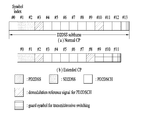
셀룰라 OFDM 무선 패킷 통신 시스템에서, 상/하향링크 데이터 패킷 전송은 서브프레임 (subframe) 단위로 이루어지며, 한 서브프레임은 다수의 OFDM 심볼을 포함하는 일정 시간 구간으로 정의된다. 3GPP LTE 표준에서는 FDD(Frequency Division Duplex)에 적용 가능한 타입 1 무선 프레임(radio frame) 구조와 TDD(Time Division Duplex)에 적용 가능한 타입 2의 무선 프레임 구조를 지원한다.
도 1(a)는 타입 1 무선 프레임의 구조를 나타내는 도면이다. 하향링크 무선 프레임(radio frame)은 10개의 서브프레임(subframe)으로 구성되고, 하나의 서브프레임은 시간 영역(time domain)에서 2개의 슬롯(slot)으로 구성된다. 하나의 서브프레임이 전송되는 데 걸리는 시간을 TTI(transmission time interval)이라 하고, 예를 들어 하나의 서브프레임의 길이는 1ms이고, 하나의 슬롯의 길이는 0.5ms 일 수 있다. 하나의 슬롯은 시간 영역에서 복수의 OFDM 심볼을 포함하고, 주파수 영역에서 다수의 자원블록(Resource Block; RB)을 포함한다. 3GPP LTE/LTE-A 시스템에서는 하향링크에서 OFDMA 를 사용하므로, OFDM 심볼이 하나의 심볼 구간을 나타낸다. OFDM 심볼은 또한 SC-FDMA 심볼 또는 심볼 구간으로 칭하여질 수도 있다. 자원 블록(Resource Block; RB)은 자원 할당 단위이고, 하나의 블록에서 복수개의 연속적인 부반송파(subcarrier)를 포함할 수 있다.
하나의 슬롯에 포함되는 OFDM 심볼의 수는 CP(Cyclic Prefix)의 구성(configuration)에 따라 달라질 수 있다. CP에는 확장된 CP(extended CP)와 일반 CP(normal CP)가 있다. 예를 들어, OFDM 심볼이 일반 CP에 의해 구성된 경우, 하나의 슬롯에 포함되는 OFDM 심볼의 수는 7개일 수 있다. OFDM 심볼이 확장된 CP에 의해 구성된 경우, 한 OFDM 심볼의 길이가 늘어나므로, 한 슬롯에 포함되는 OFDM 심볼의 수는 일반 CP인 경우보다 적다. 확장된 CP의 경우에, 예를 들어, 하나의 슬롯에 포함되는 OFDM 심볼의 수는 6개일 수 있다. 단말이 빠른 속도로 이동하는 등의 경우와 같이 채널상태가 불안정한 경우, 심볼간 간섭을 더욱 줄이기 위해 확장된 CP가 사용될 수 있다.
일반 CP가 사용되는 경우 하나의 슬롯은 7개의 OFDM 심볼을 포함하므로, 하나의 서브프레임은 14개의 OFDM 심볼을 포함한다. 이때, 각 서브프레임의 처음 2개 또는 3개의 OFDM 심볼은 PDCCH(physical downlink control channel)에 할당되고, 나머지 OFDM 심볼은 PDSCH(physical downlink shared channel)에 할당될 수 있다.
도 1(b)는 타입 2 무선 프레임의 구조를 나타내는 도면이다. 타입 2 무선 프레임은 2개의 해프 프레임 (half frame)으로 구성되며, 각 해프 프레임은 5개의 서브프레임과 DwPTS (Downlink Pilot Time Slot), 보호구간(Guard Period; GP), UpPTS (Uplink Pilot Time Slot)로 구성되며, 이 중 1개의 서브프레임은 2개의 슬롯으로 구성된다. DwPTS는 단말에서의 초기 셀 탐색, 동기화 또는 채널 추정에 사용된다. UpPTS는 기지국에서의 채널 추정과 단말의 상향 전송 동기를 맞추는 데 사용된다. 보호구간은 상향링크와 하향링크 사이에 하향링크 신호의 다중경로 지연으로 인해 상향링크에서 생기는 간섭을 제거하기 위한 구간이다. 한편, 무선 프레임의 타입에 관계 없이 1개의 서브프레임은 2개의 슬롯으로 구성된다.
무선 프레임의 구조는 예시에 불과하고, 무선 프레임에 포함되는 서브프레임의 수 또는 서브프레임에 포함되는 슬롯의 수, 슬롯에 포함되는 심볼의 수는 다양하게 변경될 수 있다.
도 2는 하향링크 슬롯에서의 자원 그리드(resource grid)를 나타내는 도면이다. 하나의 하향링크 슬롯은 시간 영역에서 7 개의 OFDM 심볼을 포함하고, 하나의 자원블록(RB)은 주파수 영역에서 12 개의 부반송파를 포함하는 것으로 도시되어 있지만, 본 발명이 이에 제한되는 것은 아니다. 예를 들어, 일반 CP(Cyclic Prefix)의 경우에는 하나의 슬롯이 7 OFDM 심볼을 포함하지만, 확장된 CP(extended-CP)의 경우에는 하나의 슬롯이 6 OFDM 심볼을 포함할 수 있다. 자원 그리드 상의 각각의 요소는 자원 요소(resource element)라 한다. 하나의 자원블록은 12×7 자원 요소를 포함한다. 하향링크 슬롯에 포함되는 자원블록들의 개수(NDL)는 하향링크 전송 대역폭에 따른다. 상향링크 슬롯의 구조는 하향링크 슬롯의 구조와 동일할 수 있다.
도 3은 하향링크 서브프레임의 구조를 나타내는 도면이다. 하나의 서브프레임 내에서 첫 번째 슬롯의 앞 부분의 최대 3 개의 OFDM 심볼은 제어 채널이 할당되는 제어 영역에 해당한다. 나머지 OFDM 심볼들은 물리하향링크공유채널(Physical Downlink Shared Channel; PDSCH)이 할당되는 데이터 영역에 해당한다. 3GPP LTE/LTE-A 시스템에서 사용되는 하향링크 제어 채널들에는, 예를 들어, 물리제어포맷지시자채널(Physical Control Format Indicator Channel; PCFICH), 물리하향링크제어채널(Physical Downlink Control Channel; PDCCH), 물리HARQ지시자채널(Physical Hybrid automatic repeat request Indicator Channel; PHICH) 등이 있다. PCFICH는 서브프레임의 첫 번째 OFDM 심볼에서 전송되고 서브프레임 내의 제어 채널 전송에 사용되는 OFDM 심볼의 개수에 대한 정보를 포함한다. PHICH는 상향링크 전송의 응답으로서 HARQ ACK/NACK 신호를 포함한다. PDCCH를 통하여 전송되는 제어 정보를 하향링크제어정보(Downlink Control Information; DCI)라 한다. DCI는 상향링크 또는 하향링크 스케듈링 정보를 포함하거나 임의의 단말 그룹에 대한 상향링크 전송 전력 제어 명령을 포함한다. PDCCH는 하향링크공유채널(DL-SCH)의 자원 할당 및 전송 포맷, 상향링크공유채널(UL-SCH)의 자원 할당 정보, 페이징채널(PCH)의 페이징 정보, DL-SCH 상의 시스템 정보, PDSCH 상으로 전송되는 임의접속응답(Random Access Response)과 같은 상위계층 제어 메시지의 자원 할당, 임의의 단말 그룹 내의 개별 단말에 대한 전송 전력 제어 명령의 세트, 전송 전력 제어 정보, VoIP(Voice over IP)의 활성화 등을 포함할 수 있다. 복수의 PDCCH가 제어 영역 내에서 전송될 수 있다. 단말은 복수의 PDCCH를 모니터링할 수 있다. PDCCH는 하나 이상의 연속하는 제어채널요소(Control Channel Element; CCE)의 조합(aggregation)으로 전송된다. CCE는 무선 채널의 상태에 기초한 코딩 레이트로 PDCCH를 제공하기 위해 사용되는 논리 할당 단위이다. CCE는 복수개의 자원 요소 그룹에 대응한다. PDCCH를 위해 필요한 CCE의 개수는 DCI의 크기와 코딩 레이트 등에 따라 달라질 수 있다. 예를 들어, PDCCH 전송에는 CCE 개수 1, 2, 4, 8(각각 PDCCH 포맷 0, 1, 2, 3에 대응)개 중 어느 하나가 사용될 수 있으며, DCI의 크기가 큰 경우 및/또는 채널 상태가 좋지 않아 낮은 코딩 레이트가 필요한 경우 상대적으로 많은 개수의 CCE가 하나의 PDCCH 전송을 위해 사용될 수 있다. 기지국은 단말에게 전송되는 DCI의 크기, 셀 대역폭, 하향링크 안테나 포트의 개수, PHICH 자원 양 등을 고려하여 PDCCH 포맷을 결정하고, 제어 정보에 순환잉여검사(Cyclic Redundancy Check; CRC)를 부가한다. CRC는 PDCCH의 소유자 또는 용도에 따라 무선 네트워크 임시 식별자(Radio Network Temporary Identifier; RNTI)라 하는 식별자로 마스킹된다. PDCCH가 특정 단말에 대한 것이면, 단말의 cell-RNTI(C-RNTI) 식별자가 CRC에 마스킹될 수 있다. 또는, PDCCH가 페이징 메시지에 대한 것이면, 페이징 지시자 식별자(Paging Indicator Identifier; P-RNTI)가 CRC에 마스킹될 수 있다. PDCCH가 시스템 정보(보다 구체적으로, 시스템 정보 블록(SIB))에 대한 것이면, 시스템 정보 식별자 및 시스템 정보 RNTI(SI-RNTI)가 CRC에 마스킹될 수 있다. 단말의 임의 접속 프리앰블의 전송에 대한 응답인 임의접속응답을 나타내기 위해, 임의접속-RNTI(RA-RNTI)가 CRC에 마스킹될 수 있다.
도 4는 상향링크 서브프레임의 구조를 나타내는 도면이다. 상향링크 서브프레임은 주파수 영역에서 제어 영역과 데이터 영역으로 분할될 수 있다. 제어 영역에는 상향링크 제어 정보를 포함하는 물리상향링크제어채널(Physical Uplink Control Channel; PUCCH)이 할당된다. 데이터 영역에는 사용자 데이터를 포함하는 물리상향링크공유채널(Physical Uplink Shared Channel; PUSCH)이 할당된다. 단일 반송파 특성을 유지하기 위해서, 하나의 단말은 PUCCH와 PUSCH를 동시에 전송하지 않는다. 하나의 단말에 대한 PUCCH는 서브프레임에서 자원블록 쌍(RB pair)에 할당된다. 자원블록 쌍에 속하는 자원블록들은 2 슬롯에 대하여 상이한 부반송파를 차지한다. 이를 PUCCH에 할당되는 자원블록 쌍이 슬롯 경계에서 주파수-호핑(frequency-hopped)된다고 한다.
참조 신호 (Reference Signal; RS)
무선 통신 시스템에서 패킷을 전송할 때, 전송되는 패킷은 무선 채널을 통해서 전송되기 때문에 전송과정에서 신호의 왜곡이 발생할 수 있다. 왜곡된 신호를 수신측에서 올바로 수신하기 위해서는 채널 정보를 이용하여 수신 신호에서 왜곡을 보정하여야 한다. 채널 정보를 알아내기 위해서, 송신측과 수신측에서 모두 알고 있는 신호를 전송하여, 상기 신호가 채널을 통해 수신될 때의 왜곡 정도를 가지고 채널 정보를 알아내는 방법을 주로 사용한다. 상기 신호를 파일럿 신호(Pilot Signal) 또는 참조신호(Reference Signal)라고 한다.
다중안테나를 사용하여 데이터를 송수신하는 경우에는 각 송신 안테나와 수신 안테나 사이의 채널 상황을 알아야 올바른 신호를 수신할 수 있다. 따라서, 각 송신 안테나 별로, 좀더 자세하게는 안테나 포트(port)별로 별도의 참조신호가 존재하여야 한다.
참조신호는 상향링크 참조신호와 하향링크 참조신호로 구분될 수 있다. 현재 LTE 시스템에는 상향링크 참조신호로써,
i) PUSCH 및 PUCCH를 통해 전송된 정보의 코히런트(coherent)한 복조를 위한 채널 추정을 위한 복조 참조신호(DeModulation-Reference Signal, DM-RS)
ii) 기지국이, 네트워크가 다른 주파수에서의 상향링크 채널 품질을 측정하기 위한 사운딩 참조신호(Sounding Reference Signal, SRS)가 있다.
한편, 하향링크 참조신호에는,
i) 셀 내의 모든 단말이 공유하는 셀-특정 참조신호(Cell-specific Reference Signal, CRS)
ii) 특정 단말만을 위한 단말-특정 참조신호(UE-specific Reference Signal)
iii) PDSCH가 전송되는 경우 코히런트한 복조를 위해 전송되는 (DeModulation-Reference Signal, DM-RS)
iv) 하향링크 DMRS가 전송되는 경우 채널 상태 정보(Channel State Information; CSI)를 전달하기 위한 채널상태정보 참조신호(Channel State Information- Reference Signal, CSI-RS)
v) MBSFN(Multimedia Broadcast Single Frequency Network) 모드로 전송되는 신호에 대한 코히런트한 복조를 위해 전송되는 MBSFN 참조신호(MBSFN Reference Signal)
vi) 단말의 지리적 위치 정보를 추정하는데 사용되는 위치 참조신호(Positioning Reference Signal)가 있다.
참조신호는 그 목적에 따라 크게 두 가지로 구분될 수 있다. 채널 정보 획득을 위한 목적의 참조신호와 데이터 복조를 위해 사용되는 참조신호가 있다. 전자는 UE가 하향 링크로의 채널 정보를 획득하는데 그 목적이 있으므로 광대역으로 전송되어야 하고, 특정 서브 프레임에서 하향 링크 데이터를 수신하지 않는 단말이라도 그 참조신호를 수신하여야 한다. 또한 이는 핸드오버 등의 상황에서도 사용된다. 후자는 기지국이 하향링크를 보낼 때 해당 리소스에 함께 보내는 참조신호로서, 단말은 해당 참조신호를 수신함으로써 채널 측정을 하여 데이터를 복조할 수 있게 된다. 이 참조신호는 데이터가 전송되는 영역에 전송되어야 한다.
다중안테나(MIMO) 시스템의 모델링
도 5는 다중안테나를 갖는 무선 통신 시스템의 구성도이다.
도 5(a)에 도시된 바와 같이 송신 안테나의 수를 Nt 개로, 수신 안테나의 수를 NR 개로 늘리면, 송신기나 수신기에서만 다수의 안테나를 사용하게 되는 경우와 달리 안테나 수에 비례하여 이론적인 채널 전송 용량이 증가한다. 따라서, 전송 레이트를 향상시키고 주파수 효율을 획기적으로 향상시킬 수 있다. 채널 전송 용량이 증가함에 따라, 전송 레이트는 이론적으로 단일 안테나 이용시의 최대 전송 레이트(Ro)에 레이트 증가율(Ri)이 곱해진 만큼 증가할 수 있다.
예를 들어, 4개의 송신 안테나와 4개의 수신 안테나를 이용하는 MIMO 통신 시스템에서는 단일 안테나 시스템에 비해 이론상 4배의 전송 레이트를 획득할 수 있다. 다중안테나 시스템의 이론적 용량 증가가 90 년대 중반에 증명된 이후 이를 실질적인 데이터 전송률 향상으로 이끌어 내기 위한 다양한 기술들이 현재까지 활발히 연구되고 있다. 또한, 몇몇 기술들은 이미 3 세대 이동 통신과 차세대 무선랜 등의 다양한 무선 통신의 표준에 반영되고 있다.
현재까지의 다중안테나 관련 연구 동향을 살펴보면 다양한 채널 환경 및 다중접속 환경에서의 다중안테나 통신 용량 계산 등과 관련된 정보 이론 측면 연구, 다중안테나 시스템의 무선 채널 측정 및 모형 도출 연구, 전송 신뢰도 향상 및 전송률 향상을 위한 시공간 신호 처리 기술 연구 등 다양한 관점에서 활발히 연구가 진행되고 있다.
다중안테나 시스템에서의 통신 방법을 수학적 모델링을 이용하여 보다 구체적으로 설명한다. 상기 시스템에는 Nt개의 송신 안테나와 Nt개의 수신 안테나가 존재한다고 가정한다.
송신 신호를 살펴보면, Nt개의 송신 안테나가 있는 경우 전송 가능한 최대 정보는 NT개이다. 전송 정보는 다음과 같이 표현될 수 있다.
각각의 전송 정보  는 전송 전력이 다를 수 있다. 각각의 전송 전력을
  라고 하면, 전송 전력이 조정된 전송 정보는 다음과 같이 표현될 수 있다.
또한,  는 전송 전력의 대각행렬
  를 이용해 다음과 같이 표현될 수 있다.

전송전력이 조정된 정보 벡터  에 가중치 행렬
  가 적용되어 실제 전송되는 Nt개의 송신신호
  가 구성되는 경우를 고려해 보자. 가중치 행렬
  는 전송 정보를 전송 채널 상황 등에 따라 각 안테나에 적절히 분배해 주는 역할을 한다.
  는 벡터
는 벡터  를 이용하여 다음과 같이 표현될 수 있다.

여기에서,  는 i번째 송신 안테나와 j번째 정보간의 가중치를 의미한다.
  는 프리코딩 행렬이라고도 불린다.
수신신호는 Nr개의 수신 안테나가 있는 경우 각 안테나의 수신신호  은 벡터로 다음과 같이 표현될 수 있다.
다중안테나 무선 통신 시스템에서 채널을 모델링하는 경우, 채널은 송수신 안테나 인덱스에 따라 구분될 수 있다. 송신 안테나 j로부터 수신 안테나 i를 거치는 채널을  로 표시하기로 한다.
  에서, 인덱스의 순서가 수신 안테나 인덱스가 먼저, 송신 안테나의 인덱스가 나중임에 유의한다.
한편, 도 5(b)은 NR개의 송신 안테나에서 수신 안테나 i로의 채널을 도시한 도면이다. 상기 채널을 묶어서 벡터 및 행렬 형태로 표시할 수 있다. 도 5(b)에서, 총 NT개의 송신 안테나로부터 수신 안테나 i로 도착하는 채널은 다음과 같이 나타낼 수 있다.
따라서, Nt개의 송신 안테나로부터 Nr개의 수신 안테나로 도착하는 모든 채널은 다음과 같이 표현될 수 있다.

실제 채널에는 채널 행렬  를 거친 후에 백색잡음(AWGN; Additive White Gaussian Noise)이 더해진다. NR개의 수신 안테나 각각에 더해지는 백색잡음
  은 다음과 같이 표현될 수 있다.
상술한 수식 모델링을 통해 수신신호는 다음과 같이 표현될 수 있다.

한편, 채널 상태를 나타내는 채널 행렬  의 행과 열의 수는 송수신 안테나의 수에 의해 결정된다. 채널 행렬
  에서 행의 수는 수신 안테나의 수 NR과 같고, 열의 수는 송신 안테나의 수 Nt와 같다. 즉, 채널 행렬
  는 행렬이 NR×Nt된다.
행렬의 랭크(rank)는 서로 독립인(independent) 행 또는 열의 개수 중에서 최소 개수로 정의된다. 따라서, 행렬의 랭크는 행 또는 열의 개수 보다 클 수 없다. 채널 행렬  의 랭크(
의 랭크( )는 다음과 같이 제한된다.
랭크의 다른 정의는 행렬을 고유치 분해(Eigen value decomposition) 하였을 때, 0이 아닌 고유치들의 개수로 정의할 수 있다. 유사하게, 랭크의 또 다른 정의는 특이치 분해(singular value decomposition) 하였을 때, 0이 아닌 특이치들의 개수로 정의할 수 있다. 따라서, 채널 행렬에서 랭크. 의 물리적인 의미는 주어진 채널에서 서로 다른 정보를 보낼 수 있는 최대 수라고 할 수 있다.
본 문서의 설명에 있어서, MIMO 전송에 대한 '랭크(Rank)' 는 특정 시점 및 특정 주파수 자원에서 독립적으로 신호를 전송할 수 있는 경로의 수를 나타내며, '레이어(layer)의 개수' 는 각 경로를 통해 전송되는 신호 스트림의 개수를 나타낸다. 일반적으로 송신단은 신호 전송에 이용되는 랭크 수에 대응하는 개수의 레이어를 전송하기 때문에 특별한 언급이 없는 한 랭크는 레이어 개수와 동일한 의미를 가진다.
D2D
단말의 동기 획득
이하에서는 상술한 설명 및 기존 LTE/LTE-A 시스템에 기초하여, D2D 통신에서 단말간 동기 획득에 대해 설명한다. OFDM 시스템에서는 시간/주파수 동기가 맞지 않을 경우 셀 간 간섭(Inter-Cell Interference)로 인해 OFDM 신호에서 서로 다른 단말 간에 멀티플렉싱이 불가능질 수 있다. 동기를 맞추기 위해 D2D 단말들이 직접 동기 신호를 송수신하여 모든 단말이 개별적으로 동기를 맞추는 것은 비효율적이다. 따라서, D2D와 같은 분산 노드 시스템에서는 특정 노드가 대표 동기 신호를 전송해주고 나머지 UE들이 이에 동기를 맞출 수 있다. 다시 말해, D2D 신호 송수신을 위해 일부 노드들이 (이때 노드는 eNB, UE, SRN(synchronization reference node 또는 synchronization source로 불릴 수도 있다) 일 수도 있다.) D2D 동기 신호(D2DSS, D2D Synchronization Signal)를 전송하고, 나머지 단말들이 이에 동기를 맞추어 신호를 송수신하는 방식이 사용될 수 있다.
D2D 동기신호에는 프라이머리 동기 신호(PD2DSS(Primary D2DSS 또는 PSSS(Primary Sidelink synchronization signal)), 세컨더리 동기 신호(SD2DSS(Secondary D2DSS 또는 SSSS(Secondary Sidelink synchronization signal))가 있을 수 있다. PD2DSS는 소정 길이의 자도프 추 시퀀스(Zadoff-chu 시퀀스) 또는 PSS와 유사/변형/반복된 구조 등일 수 있다. 또한 DL PSS와 달리 다른 자도프 추 루트 인덱스(예를 들어, 26, 37)를 사용할 수 있다. SD2DSS는 M-시퀀스 또는 SSS와 유사/변형/반복된 구조 등일 수 있다. 만약 단말들이 eNB로부터 동기를 맞출 경우, SRN은 eNB가 되며, D2DSS는 PSS/SSS가 된다. DL의 PSS/SSS와 달리 PD2DSS/SD2DSS는 UL 서브캐리어 매핑 방식을 따른다. 도 6에는 D2D동기 신호가 전송되는 서브프레임이 도시되어 있다. PD2DSCH(Physical D2D synchronization channel)는 D2D 신호 송수신 전에 단말이 가장 먼저 알아야 하는 기본이 되는 (시스템) 정보(예를 들어, D2DSS에 관련된 정보, 듀플렉스 모드(Duplex Mode, DM), TDD UL/DL 구성, 리소스 풀 관련 정보, D2DSS에 관련된 애플리케이션의 종류, subframe offset, 브로드캐스트 정보 등)가 전송되는 (방송) 채널일 수 있다. PD2DSCH는 D2DSS와 동일한 서브프레임 상에서 또는 후행하는 서브프레임 상에서 전송될 수 있다. DMRS는 PD2DSCH의 복조를 위해 사용될 수 있다.
SRN은 D2DSS, PD2DSCH(Physical D2D synchronization channel)를 전송하는 노드일 수 있다. D2DSS는 특정 시퀀스 형태일 수 있고, PD2DSCH는 특정 정보를 나타내는 시퀀스거나 사전에 정해진 채널 코딩을 거친 후의 코드 워드 형태일 수 있다. 여기서, SRN은 eNB 또는 특정 D2D 단말이 될 수 있다. 부분 네트워크 커버리지(partial network coverage) 또는 커버리지 바깥(out of network coverage)의 경우에는 단말이 SRN이 될 수 있다.
도 7과 같은 상황에서 커버리지 밖(out of coverage) 단말과의 D2D 통신을 위해 D2DSS는 릴레이 될 수 있다. 또한, D2DSS는 다중 홉을 통해 릴레이될 수 있다. 이하의 설명에서 동기 신호를 릴레이 한다는 것은 직접 기지국의 동기신호를 AF 릴레이하는 것뿐만 아니라, 동기 신호 수신 시점에 맞추어 별도의 포맷의 D2D 동기신호를 전송하는 것도 포함하는 개념이다. 이와 같이, D2D 동기 신호가 릴레이 됨으로써 커버리지 안 단말과 커버리지 밖 단말이 직접 통신을 수행할 수 있다.
D2D
리소스
풀
도 8에는 D2D 통신을 수행하는 UE1, UE2 및 이들이 사용하는 D2D 리소스 풀의 예가 도시되어 있다. 도 8(a)에서 UE는 단말 또는 D2D 통신 방식에 따라 신호를 송수신하는 기지국 등의 네트워크 장비를 의미한다. 단말은 일련의 자원의 집합을 의미하는 리소스 풀 내에서 특정한 자원에 해당하는 리소스 유닛을 선택하고 해당 리소스 유닛을 사용하여 D2D 신호를 송신할 수 있다. 수신 단말(UE2)는 UE1이 신호를 전송할 수 있는 리소스 풀을 구성(configured) 받고 해당 pool내에서 UE1의 신호를 검출할 수 있다. 여기서 리소스 풀은 UE1이 기지국의 연결 범위에 있는 경우 기지국이 알려줄 수 있으며, 기지국의 연결 범위 밖에 있는 경우에는 다른 단말이 알려주거나 또는 사전에 정해진 자원으로 결정될 수도 있다. 일반적으로 리소스 풀은 복수의 리소스 유닛으로 구성되며 각 단말은 하나 또는 복수의 리소스 유닛을 선정하여 자신의 D2D 신호 송신에 사용할 수 있다. 리소스 유닛은 도 8(b)에 예시된 것과 같을 수 있다. 도 8(b)를 참조하면, 전체 주파수 자원이 NF개로 분할되고 전체 시간 자원이 NT개로 분할되어 총 NF*NT개의 리소스 유닛이 정의되는 것을 알 수 있다. 여기서는 해당 리소스 풀이 NT 서브프레임을 주기로 반복된다고 할 수 있다. 특히, 하나의 리소스 유닛이 도시된 바와 같이 주기적으로 반복하여 나타날 수 있다. 또는, 시간이나 주파수 차원에서의 다이버시티 효과를 얻기 위해, 하나의 논리적인 리소스 유닛이 매핑되는 물리적 리소스 유닛의 인댁스가 시간에 따라서 사전에 정해진 패턴으로 변화할 수도 있다. 이러한 리소스 유닛 구조에 있어서 리소스 풀이란 D2D 신호를 송신하고자 하는 단말이 송신에 사용할 수 있는 리소스 유닛의 집합을 의미할 수 있다.
리소스 풀은 여러 종류로 세분화될 수 있다. 먼저 각 리소스 풀에서 전송되는 D2D 신호의 컨텐츠(contents)에 따라서 구분될 수 있다. 예를 들어, D2D 신호의 컨텐츠는 구분될 수 있으며, 각각에 대하여 별도의 리소스 풀이 구성될 수 있다. D2D 신호의 컨텐츠로서, SA(Scheduling assignment (SA), D2D 데이터 채널, 디스커버리 채널(Discovery channel)이 있을 수 있다. SA는 송신 단말이 후행하는 D2D 데이터 채널의 전송으로 사용하는 리소스의 위치 및 그 외 데이터 채널의 복조를 위해서 필요한 MCS(modulation and coding scheme)나 MIMO 전송 방식, TA(timing advance)등의 정보를 포함하는 신호일 수 있다. 이 신호는 동일 리소스 유닛 상에서 D2D 데이터와 함께 멀티플렉싱되어 전송되는 것도 가능하며, 이 경우 SA 리소스 풀이란 SA가 D2D 데이터와 멀티플렉싱되어 전송되는 리소스의 풀을 의미할 수 있다. 다른 이름으로 D2D 제어 채널(control channel), PSCCH(physical sidelink control channel)로 불릴 수도 있다. D2D 데이터 채널(또는, PSSCH(Physical sidelink shared channel))은, 송신 단말이 사용자 데이터를 전송하는데 사용하는 리소스의 pool일 수 있다. 만일 동일 리소스 유닛 상에서 D2D 데이터와 함께 SA가 멀티플렉싱되어 전송되는 경우 D2D 데이터 채널을 위한 리소스 풀에서는 SA 정보를 제외한 형태의 D2D 데이터 채널만이 전송 될 수 있다. 다시 말하면 SA 리소스 풀 내의 개별 리소스 유닛 상에서 SA 정보를 전송하는데 사용되었던 REs를 D2D 데이터 채널 리소스 풀에서는 여전히 D2D 데이터를 전송하는데 사용할 수 있다. 디스커버리 채널은 송신 단말이 자신의 ID 등의 정보를 전송하여 인접 단말로 하여금 자신을 발견할 수 있도록 하는 메시지를 위한 리소스 풀일 수 있다.
D2D 신호의 컨텐츠가 동일한 경우에도 D2D 신호의 송수신 속성에 따라서 상이한 리소스 풀을 사용할 수 있다. 예를 들어, 동일한 D2D 데이터 채널이나 디스커버리 메시지라 하더라도 D2D 신호의 송신 타이밍 결정 방식(예를 들어 동기 기준 신호의 수신 시점에서 송신되는지 아니면 거기에서 일정한 TA를 적용하여 전송되는지)이나 자원 할당 방식(예를 들어 개별 신호의 전송 자원을 eNB가 개별 송신 UE에게 지정해주는지 아니면 개별 송신 UE가 pool 내에서 자체적으로 개별 신호 전송 자원을 선택하는지), 신호 포맷(예를 들어 각 D2D 신호가 한 서브프레임에서 차지하는 심볼의 개수나, 한 D2D 신호의 전송에 사용되는 서브프레임의 개수), eNB로부터의 신호 세기, D2D UE의 송신 전력 세기 등에 따라서 다시 상이한 리소스 풀로 구분될 수 있다. 설명의 편의상 D2D 커뮤니케이션에서 eNB가 D2D 송신 UE의 송신 자원을 직접 지시하는 방법을 Mode 1, 전송 자원 영역이 사전에 설정되어 있거나, eNB가 전송 자원 영역을 지정하고, UE가 직접 송신 자원을 선택하는 방법을 Mode 2라 부르기로 한다. D2D discovery의 경우에는 eNB가 직접 자원을 지시하는 경우에는 Type 2, 사전에 설정된 자원영역 또는 eNB가 지시한 자원 영역에서 UE가 직접 전송 자원을 선택하는 경우는 Type 1이라 부르기로 한다.
SA의 송수신
모드 1 단말은 기지국으로부터 구성 받은 자원을 통해 SA(또는, D2D 제어 신호, SCI(Sidelink Control Information))을 전송할 수 있다. 모드 2 단말은 기지국으로부터 D2D 송신에 사용할 리소스를 구성 받는(configured)다. 그리고, 구성 받은 그 리소스에서 시간 주파수 자원을 선택하여 SA를 전송할 수 있다.
SA 주기는 도 9에 도시된 바와 같이 정의된 것일 수 있다. 도 9을 참조하면, 첫 번째 SA 주기는 특정 시스템 프레임으로부터 상위계층시그널링에 의해 지시된 소정 오프셋(SAOffsetIndicator)만큼 떨어진 서브프레임에서 시작될 수 있다. 각 SA 주기는 SA 리소스 풀과 D2D 데이터 전송을 위한 서브프레임 풀을 포함할 수 있다. SA 리소스 풀은 SA 주기의 첫 번째 서브프레임부터 서브프레임 비트맵(saSubframeBitmap)에서 SA가 전송되는 것으로 지시된 서브프레임 중 마지막 서브프레임을 포함할 수 있다. D2D 데이터 전송을 위한 리소스 풀은, 모드 1의 경우, T-RPT(Time-resource pattern for transmission)가 적용됨으로써 실제 데이터 전송에 사용되는 서브프레임이 결정될 수 있다. 도시된 바와 같이, SA 리소스 풀을 제외한 SA 주기에 포함된 서브프레임의 개수가 T-RPT 비트 개수보다 많은 경우 T-RPT는 반복하여 적용될 수 있으며, 마지막으로 적용되는 T-RPT는 남은 서브프레임 개수만큼 truncated되어 적용될 수 있다. SA는 데이터의 전송위치를 T-RPT형태로 지시할 수도 있고, 다른 명시적인 방법으로 지시할 수도 있다. 일례로 데이터의 전송 시작 위치, 반복 횟수등을 지시하는 형태일 수 있다. 보다 일반적으로 SA는 데이터의 전송 자원의 시간, 주파수 위치를 지시하고, 데이터 디코딩에 필요한 부가 정보를 포함하여 전송하는 채널이다. 이러한 SA 리소스 풀은 데이터 풀과 분리될 수도 있지만, 데이터 풀과 일부 중첩 되어 데이터 영역을 일부 함께 사용하는 형태일 수도 있다. 또한 데이터 풀과 SA 리소스 풀이 시간영역에서 분리된 형태가 아니라 주파수 영역에서 분리된 형태일 수 있다.
이하에서는 상술한 설명에 기초하여, 본 발명의 실시예에 의한, D2D UE간 직접 신호를 주고 받아서 레인징 및 포지셔닝을 수행하는 방법에 대해 살펴본다. 종래 Wifi에서는 RTT를 측정하기 위해서 즉시 응답(immediately acknowledgement)을 이용할 수 있다. 하나의 STA(mobile device)가 unicast 데이터를 AP로 전송하고 나서 ACK을 수신하는 시점을 측정하여 RTT를 측정할 수 있다. 또는 RTS(request to send)를 전송하고 CTS (clear to send)를 수신하는 시점을 측정하여 RTT를 측정할 수 있다. 하지만 Wifi 네트워크에서 RTC/CTS를 off시킨 네트워크가 있을 수 있기 때문에 그러한 네트워크에서는 RTS/CTS를 이용한 RTT 측정이 불가능 하다. 이러한 WiFi의 레인징 방식을 셀룰러 통신에서 그대로 사용하기는 무리가 있다. 셀룰러 통신에서 레인징을 위해 특정 UE가 Wifi와 같이 바로 ACK을 전송하게 되면 다른 UE로 ICI를 발생시켜서 심각한 성능 저하를 야기할 수 있기 때문이다. 이하 실시예에서는 이와 같이 ICI 간섭을 최소화하면서 레인징을 수행하는 실시예들에 대해 살펴본다.
실시예 1
실시예 1은 도 10에 예시된 바와 같이 제1 단말(UE A)와 제2 단말(UE B)가 R m 떨어져 있다고 가정할 때, 거리를 추정, RTT를 측정하는 방법에 관한 것이다.
제1 단말은 서브프레임 N에서, D2D 신호를 전송할 수 있다. 이후, D2D 신호가 수신된 시점을 서브프레임 경계로 설정한 제2 단말로부터, 서브프레임 N+K에서, D2D 신호를 수신할 수 있다. 여기서 K는 사전에 정해지거나 네트웍에 의해 시그널링 된 값일 수 있다. 제1 단말이 제2 단말이 전송한 D2D 신호의 수신 시점을 검출하여 RTT (round trip time)를 측정할 수 있다. 즉, D2D capable한 두 단말 중, UE A가 D2D 신호를 송신하고, UE B는 UE A의 신호를 수신한 시점을 서브프레임 바운더리로 설정하고 이후 약속된 서브프레임에서 D2D 신호를 송신하는 것이다. UE A는 약속된 서브프레임에서 UE B의 신호 수신 시점을 검출하여 RTT (round trip time)을 측정하여 레인징을 수행할 수 있다. 여기서 RTT는 제2 단말이 전송한 D2D 신호의 수신 시점과 제1 단말이 N+K 서브프레임의 시작점의 차이를 전자기파 속도로 나눈 것일 수 있다.
제1 단말이 서브프레임 N에서 전송한 D2D 신호는, 디스커버리 신호, D2D 커뮤니케이션 신호, SLSS (sidelink synchronization signal) 중 하나일 수 있다. 예를 들어, SLSS가 제1 단말이 레인징을 위해 전송한다면, 제2 단말은 SLSS 수신 시점을 서브프레임 바운더리로 설정하여 신호를 송신하는 것이 된다. 즉, in coverage에서도 DL 타이밍을 서브프레임 바운더리로 설정하는 것이 아니라, SLSS수신 시점을 서브프레임 바운더리로 설정하여 신호를 송신하는 것이 된다.
앞서 설명에서는 제1 단말이 전송하는 신호를 D2D 신호라 하였으나, D2D 신호가 아닌 기존의 UL 신호 중 하나일 수도 있다. 즉, DMRS나 SRS와 같이 시퀀스형태의 신호일 수도 있고, PUSCH나 sidelink discovery/communication (shared) channel와 같은 데이타 패킷 형태의 신호일 수도 있다.
제2 단말이 회신하는 신호는, 제1 단말이 전송하는 신호와 마찬가지로, 기존의 UL 신호 중 하나일 수도 있고, 사이드링크 (예를 들어, D2D) 신호일 수도 있다. UL 신호인 경우 DMRS나 SRS와 같이 시퀀스형태의 신호일 수도 있고, PUSCH와 같은 데이타 패킷 형태의 신호일 수도 있다. 사이드링크 신호인 경우 SLSS (sidelink synchronization signal)이거나, 디스커버리 신호, 또는 D2D 커뮤니케이션 신호와 같거나 유사한 형태의 신호일 수 있다. 여기서, 제2 단말이 전송한 (D2D) 신호는 제1 단말의 위치 정보를 포함할 수 있으며, 제1 단말의 위치 정보는 위도(latitude), 경도(longitude), 고도(height) 중 하나 이상을 포함할 수 있다. 이 경우, 제1 단말이 RTT를 측정함과 동시에 제2 단말이 대략 어떤 절대 위치의 반경에 있는지 알 수 있게 된다. 이러한 위치 정보는 레인징 과정에서 제2 단말이 별도로 전송해 줄 수도 있다.
실시예 1에서는 제1 단말이 전송한 신호를 수신한 제2 단말이 이를 기준으로 신호를 전송하고, 따라서 제1 단말이 자신이 신호를 송신한 시점을 기준으로 되돌아오는 신호의 시점을 추정하므로, 레인징을 위한 제1 신호의 전송은 어떠한 타이밍을 사용하더라도 무방하다. 예를 들어, DL 타이밍 또는 UL 타이밍을 사용하여 D2D 신호를 송신할 수 있다. 이때 UE B는 UE A의 D2D 신호를 검출시점을 기준으로 약속된 서브프레임에서 이에 대한 회신 신호를 전송할 수 있다.
계속해서, N, K와 관련하여, 도 11에는 제1 단말(UE A)와 제2 단말(UE B)의 신호 송수신과 RTT 측정이 도시되어 있다. N, K 는 사전에 정해지거나, 또는 N, K 중 적어도 하나 이상은 네트워크에 의해 구성(configure)된 것일 수 있다. 예를 들어 N과 K는 사이드링크 (UE 간) 레인징을 위한 별도의 리소스로 (네트워크에 의해 물리계층 또는 상위계층 신호로 레인징 신호 송수신 UE에게) 구성되거나 사전에 정해진 값일 수 있다. 이때, N과 K 둘 중 하나는 네트워크에 의해 구성되고, 다른 하나는 사전에 정해진 값을 사용할 수도 있다. 예를 들어, K=4와 같이 사전에 정해진 값일 수 있다. 또는 K는 a(a는 사전에 정해지거나, 네트워크에 의해 구성될 수 있는 값)이상이면서, D2D 리소스에 포함되는 가장 가까운 서브프레임에서 전송하도록 규칙이 정해질 수도 있다. 즉, K는 네트워크에 의해 구성된 값이며, 서브프레임 N+K가 D2D 서브프레임이 아닌 경우 서브프레임 N+K에서 (N+K보다 크면서)가장 가까운 D2D 서브프레임일 수 있다. 또는 K는 a이상이면서 b이하인 값 중에서 사전에 정해거나, 네트워크에 의해 시그널링 될 수 있다. 여기서 상한 b가 설정되는 이유는 제2 단말이 제1 단말 신호를 수신 하고 나서 너무 많은 시간이 지나서 신호를 회신하게 되면 제2 단말 및/또는 제1 단말의 위치가 변하여 잘못된 RTT를 추정하게 되기 때문이다.
레인징을 위한 신호 송수신 리소스와 관련하여, 디스커버리와 연계된 자원할당이 이루어질 수 있다. 디스커버리 리소스 이후 X개의 서브프레임은 D2D 레인징을 위해 네트워크에 의해 구성되거나 또는 미리 구성(preconfigured)될 수 있다. 이러한 레인징에 관련된 사이드링크 리소스는 네트워크에 의해 물리계층 또는 상위계층 신호로 구성되거나, (UE중 일부 또는 전체가 out-of-coverage에 있을 때에는) 사전에 정해진 리소스에서 레인징 목적의 신호를 송수신 할 수 있다. 또는 레인징을 수행하고자 하는 단말이 사전에 D2D 제어신호를 통해서 레인징에 사용되는 자원의 위치를 레인징 신호 수신 단말에게 시그널링 할 수 있다. 혹은 최초 레인징신호를 보낸 단말이 수신 단말에게 해당 packet을 사용하여 레인징을 수행하고, 특정 자원에서 레인징 신호에 대한 피드백을 전송하라고 지시할 수 있다.
실시예 2
실시예 2는 제1 단말이 레인징을 위한 신호를 송신하는 시점이 기지국의 DL 타이밍이나 PUSCH 타이밍이 아닌 제3의 타이밍으로 설정되는 경우에 관한 것이다.
여기서 제3의 타이밍은, DL 타이밍과 UL 타이밍의 중간 값 또는 DL 타이밍에서 TA/2만큼 오프셋을 인가한 타이밍 또는 GPS 등의 글로벌 타이밍일 수 있다. 이때 TDD에서는 추가적으로 Tx/Rx 스위칭을 위해서 624Ts 오프셋이 인가될 수도 있다. 달리 표현하면 기지국의 DL Tx 타이밍으로 신호를 송신하는 것으로 표현할 수 있으며, 이를 DL Tx 타이밍이라 부르기로 한다. 이러한 경우, DL 전송 타이밍에 모든 UE들이 전송 타이밍을 정렬하여 신호를 전송하고 제2 단말 (레인징 신호를 수신하는 UE)는 자신의 DL, UL 타이밍의 중간값 또는 TA/2인 시점으로부터 제1 단말의 신호가 수신되는 시점을 검출하여 UE사이의 전파 지연을 추정한다. 이 방법은 제2 단말이 신호를 회신하지 않아도 되기 때문에 자원 활용면에서 효율적일 수 있다.
제3의 타이밍이 글로벌 타이밍인 경우가 도 12에 예시되어 있다. 제1 단말과 제2 단말은 GPS 신호를 수신하여 공통의 타이밍 클록을 가지고 있어서 서로 같은 타이밍을 기준으로 신호를 전송할 수 있다. 이때, 각 단말의 클록이 표동(drift)하거나, 절대 시간 정보가 오차가 있어서 각 단말이 서로 다른 오차를 갖는 경우가 문제될 수 있다. 레인징에는 매우 작은 값의 타이밍 측정오차도 위치 추정에 큰 오차를 야기할 수 있기 때문에 오차를 최대한 보정하는 것이 필요하다. 예를 들어 도 12를 참조하면, 제1 단말은 a만큼의 오차를, 제2 단말은 b만큼의 절대시간 기준의 오차 또는 GPS 타이밍으로부터의 오차를 갖는다고 가정해보자. 이때 제1 단말이 제2 단말의 신호를 수신하면 d+(b-a)를 측정하게 되고, 제2 단말이 제1 단말의 신호를 수신하면 d-(b-a)의 값을 측정하게 된다. 여기서 d는 제1 단말과 B사이의 전파 지연을 의미한다. 이때, 제1 단말과 B가 서로의 전파 지연을 추정(estimate)한 전파 지연의 측정값을 디스커버리 또는 커뮤니케이션 신호를 통하여 서로에게 시그널링 할 경우 각 단말은 자신의 측정값과 다른 단말의 측정값을 평균하여 정확한 d를 추정할 수 있다.
위 동작을 위하여 각 단말은 다른 단말로부터의 전파 지연의 측정값과 자신이 발견한 단말의 ID의 또는 다른 단말을 지시할 수 있는 정보의 전체 또는 일부를 D2D 신호를 통하여 다른 단말에게 시그널링할 수 있다. 각 단말을 자신의 측정값과 다른 단말로부터 시그널링 받은 측정값을 평균하여 두 단말 사이의 클록 오차를 줄일 수 있다. 도 12에서 제1 단말은 d+(b-a)를 측정하여 이를 제2 단말에게 시그널링하고, 제2 단말은 d-(b-a)를 측정하여 제1 단말에게 시그널링할 수 있다. 각 UE들은 자신이 측정한 값과 상대 단말로부터 수신한 값을 평균하여 정확한 d를 계산할 수 있다.
제1 단말이 레인징을 위해 전송하는 D2D 신호 또는 UL 신호 그리고 전송 자원의 위치는, 기지국이 dedicated signal을 통해 지시할 수도 있고, 여러 UE group을 위하여 할당된 자원 영역에 각 UE들이 전송 자원을 선택하여 레인징 측정을 위한 신호를 송신할 수 있다. 또는, 특정 UE, UE group이 전송하는 신호를 위한 자원은 네트워크에 의해 구성되거나, preconfigured 될 수 있다.
제2 단말은 추정한 전파 지연 또는 RTT 또는 두 UE사이의 거리 또는 이와 동등한 값을 유추할 수 있는 다른 형태의 정보를 제1 단말로 물리계층 또는 상위계층 신호로 제1 단말에게 전송할 수 있다. 제1 단말 또한 마찬가지로 제2 단말이 DL TX 타이밍에 전송한 신호를 측정하여 두 UE사이의 거리를 추정할 수 있다.
한편 특정 기지국으로부터의 DL 타이밍 또는 UL 타이밍 또는 DL Tx 타이밍만 사용하여 레인징 신호를 송신할 경우, 특정 기지국의 신호가 잘 들리지 않아서 오차가 크게 발생할 수 있다. 이 경우 오차를 줄이기 위하여 기지국으로부터의 DL/UL 또는 DL Tx 타이밍을 평균한 값을 사용하여 레인징 신호를 송신하는 타이밍을 설정할 수도 있다.
이때, 기지국으로부터 신호세기가 일정 임계 이상인 (기지국으로부터의) 신호의 타이밍만을 평균하도록 규칙이 정해질 수도 있으며, 타이밍 설정에 참여하는 기지국으로부터의 신호세기를 판단하는 임계치는 사전에 정해지거나, 네트워크에 의해 구성되는 값일 수 있다.
상기 제안한 레인징을 위한 신호 송수신은 기존의 D2D 신호의 타이밍 (UL 또는 DL 타이밍)과 상이한 별도의 타이밍으로 전송되기 때문에 다른 타이밍의 신호와 다른 별도의 리소스 풀에서 전송하도록 규칙이 정해지고, 해당 리소스 풀이 물리계층 또는 상위계층 신호로 네트워크에 의해 구성될 수 있다. (out coverage의 경우는 preconfigured 리소스)
이러한 레인징을 위한 신호 송수신을 위한 자원(달리 표현하면 UL, DL 타이밍이 아닌 제 3의 타이밍으로 신호를 전송(또는 수신)하는 자원)은 디스커버리와 유사한 주기로 전송될 가능성이 있으며, 네트워크가 디스커버리 리소스 풀을 구성할 때, 추가적인 시그널링이 일어나거나, 또는 디스커버리 리소스 풀 중에 사전에 정해진 일부분에서 전송되도록 규칙이 정해질 수 있다.
또는 이러한 레인징 또는 다른 단말의 신호의 수신시점을 측정하기 위한 리소스는 'scheduling assignment + 데이터' 형태로 전송될 수 있는데, 이때 SA에서는 다른 D2D 통신의 용도와 구별하기 위하여 레인징 또는 포지셔닝 목적의 SA 포맷이나, SA ID를 설정하여 송수신을 수행할 수 있다. 여기서 SA 포맷이 다르게 설정된다는 것은 SA의 필드구성이 상이한것과 물리적인 SA의 포맷이 상이한 것을 포함한다. 이때 데이터 영역에서는 사전에 정해진 시퀀스 또는 '시퀀스 + 코드워드' 형태의 신호를 송신하여 레인징을 수행하는 단말들이 서로 신호를 주고 받을 수 있다. 예를 들어, SA는 레인징을 수행하고자 하는 단말이 송신하고 이때 SA에서 포함되어 전송되는 ID는 수신 단말이 사전에 인지할 수 있는 ID로 전송될 수 있다. 데이터 영역에서는 SA를 송신한 단말이 전송하는 자원과 SA를 수신한 단말이 전송하는 자원영역이 나뉘어져 있을 수 있다. 예를 들어, 송신단말의 T-RPT (time resource pattern for transmission)에서 짝수 번째 1의 위치에서는 송신 단말이 레인징 또는 포지셔닝 목적의 신호를 전송하고, 홀수 번째 1의 위치에서는 수신 단말이 레인징 또는 포지셔닝 목적의 신호를 전송할 수 있다. 또는 송신 단말과 수신 단말 또는 레인징을 수행할 단말 A와 B가 상대 단말에게 레인징 또는 포지셔닝 목적의 신호를 전송하는 자원 영역(리소스 풀)이 네트워크에 의해 구성되거나, 사전에 나뉘어져 있어서 이 자원 영역에서 서로 신호를 주고 받을 수 있다.
또한 이러한 'SA+데이터' 구조에서는 SA가 전송하는 타이밍과 데이터를 전송하는 타이밍이 상이할 수 있는데 예를 들어, SA의 경우에는 DL 타이밍으로 송신하고, 데이터의 경우에는 실시예 1 및 실시예 2에서 설명된 타이밍 설정 방법 중 하나(다른 UE로부터 신호를 수신한 타이밍 기준으로 송신 또는 제 3의 기기로부터 타이밍 정보를 기준으로 (예를 들어, GPS) 또는 DL (Rx) 타이밍으로부터 TA/2만큼 오프셋을 인가한 타이밍(DL Tx 타이밍)) 에서 한가지 방법으로 신호를 송신할 수 있으며, 이때 SA에서는 SA를 전송하는 타이밍과 데이터를 전송하는 타이밍간의 오프셋값을 SA의 contents중 하나로 전송해줄 수 있다.
한편 레인징이나 포지셔닝을 위한 신호의 BW는 사전에 정해지거나 네트워크에 의해 구성될 수 있는데 정확한 타이밍 추정을 위해서는 가능한한 wideband로 전송하는 것이 바람직하며, 이를 위해 시그널링 방법에서 narrow band 전송 (예를 들어 6RB 미만의 전송)은 포지셔닝 용도의 신호 전송 BW에서 제외될 수 있다. 또는 최소 NRB이상으로 전송하도록 규칙이 정해질 수 있으며 (N은 사전에 정해지거나, 네트웍에 의해 설정된 값), 경우에 따라 송신 단말이 6RB이상 100RB이하의 신호 중에서 선택하여 SA를 통하여 지시할 수 있다.
레인징 또는 포지셔닝에 사용되는 시퀀스는 DMRS와 유사한 형태일 수도 있고, PSS/SSS와 같은 형태이거나, SLSS (PSSS/SSSS)와 같은 형태 또는 그 변형된 형태일 수 있다.
단순히 타이밍만 측정하는 용도라면, 데이터 영역을 비우거나 데이터 영역을 모두 RS로 채워서 전송할 수 있으며(즉 기존의 코드워드전송 위치도 모두 RS를 전송) 또는 기존 RS 전송 위치에서만 RS를 전송하고 데이터 RE는 비운 형태로 전송할 수도 있다. 또는 기존 D2D 단말들이 사용하지 않는 서브프레임의 마지막 심볼에 타이밍/포지셔닝목적의 RS를 전송할 수 있으며, 이때에는 다음 서브프레임의 일부 심볼 또는 전체가 puncturing또는 guard region으로 설정될 수 있다. 혹은 마지막 심볼 영역에 레인징을 위한 신호를 송신할 경우 그리고 이러한 레인징을 위한 신호가 제3의 타이밍 (예를 들어 GPS 타이밍)을 사용하는 경우, 이때, D2D신호는 DL 타이밍을 사용한 경우에는 D2D신호와 레인징 신호의 심볼 경계가 중첩될 수 있다. 이를 방지하기 위해 partial 심볼 길이의 레인징 신호가 전송될 수 있다. 예를 들어 기존 심볼의 절반길이의 심볼이 D2D 서브프레임의 마지막 심볼영역내에서 전송될 수 있다. 이렇게 짧은 길이의 레인징 신호를 사용하여 D2D심볼 경계와 레인징 심볼 경계가 중첩되는 현상을 방지할 수 있다.
한편 상기 제안한 D2D 단말 사이에 레인징/포지셔닝을 하는 방법 중 전체 또는 일부는 기지국과 단말간 레인징, 단말과 단말간 타이밍 정렬 용도로 사용될 수도 있다. 즉 도 10에서 한 단말은 기지국이 될 수 있으며, 기지국과 단말 사이의 레인징 목적으로 자신의 위치정보를 물리계층 또는 상위계층 신호로 단말에게 시그널링 할 수 있다. 만일 단말이 GPS를 가진 단말이거나, 다른 위치 추정 기법을 이용하여 자신의 위치를 아는 단말의 경우 자신의 위치와 기지국의 위치를 비교하여 기지국과 단말 사이의 거리를 판별하게 되고, 이때 기지국 신호의 수신시점을 이용하여 기지국의 송신 시점을 추정할 수 있다. 이러한 기지국의 송신 시점정보를 알게 되면, 단말은 신호의 송신 시점을 기지국의 송신 시점 정보와 정렬하여 특정 신호를 전송하게 되고, 이는 단말과 단말 사이의 레인징/포지셔닝이나 D2D 통신을 용이하게 한다. 또한 이렇게 단말이나 기지국이 자신의 위치 정보를 물리계층 혹은 상위계층 신호로 주변 단말에게 송신하는 방법을 활용하여 수신 단말이 빔포밍 방향을 결정하는데 사용할 수도 있다. 예를 들어 제 1 기기가 자신의 위치 정보를 송신하였을 경우 제 2 기기가 이를 수신하고, 제 2기기는 자신의 위치와 제 1기기의 위치를 파악하여 제 1기기의 방향으로 빔포밍을 수행할 수 있다. 특히 mmwave에서는 초기 빔 탐색과정을 통해서 정확한 빔 방향을 찾는 것이 매우 중요한데, 위치 정보가 없는 경우에는 모든 방향의 빔을 전송해보고 최적의 빔방향을 찾게되지만, 위치 정보를 이용하게 될 경우 특정 방향을 먼저 탐색하기 때문에, 초기 빔 탐색과정, 시간을 상당히 줄일 수 있는 장점이 있다. 이러한 동작을 위하여 각 단말이나 기지국이 자신의 위치 정보를 송신하는 자원이 별도로 설정될 수 있으며, 각 기지국이나, 단말은 주기적, 혹은 비주기적으로 사전에 설정된 혹은 네트웍에 의해 설정된 자원에서 자신의 위치 정보를 송신한다.
상기 설명한 제안 방식에 대한 일례들 또한 본 발명의 구현 방법들 중 하나로 포함될 수 있으므로, 일종의 제안 방식들로 간주될 수 있음은 명백한 사실이다. 또한, 상기 설명한 제안 방식들은 독립적으로 구현될 수 도 있지만, 일부 제안 방식들의 조합 (혹은 병합) 형태로 구현될 수 도 있다. 상기 제안 방법들의 적용 여부 정보 (혹은 상기 제안 방법들의 규칙들에 대한 정보)는 기지국이 단말에게 사전에 정의된 시그널 (예를 들어, 물리 계층 시그널 혹은 상위 계층 시그널)을 통해서 알려주도록 규칙이 정의될 수 가 있다.
본 발명의 실시예에 의한 장치 구성
도 13은 본 발명의 실시 형태에 따른 전송포인트 장치 및 단말 장치의 구성을 도시한 도면이다.
도 13을 참조하여 본 발명에 따른 전송포인트 장치(10)는, 수신장치(11), 전송장치(12), 프로세서(13), 메모리(14) 및 복수개의 안테나(15)를 포함할 수 있다. 복수개의 안테나(15)는 MIMO 송수신을 지원하는 전송포인트 장치를 의미한다. 수신장치(11)은 단말로부터의 상향링크 상의 각종 신호, 데이터 및 정보를 수신할 수 있다. 전송장치(12)은 단말로의 하향링크 상의 각종 신호, 데이터 및 정보를 전송할 수 있다. 프로세서(13)는 전송포인트 장치(10) 전반의 동작을 제어할 수 있다.
본 발명의 일 실시예에 따른 전송포인트 장치(10)의 프로세서(13)는, 앞서 설명된 각 실시예들에서 필요한 사항들을 처리할 수 있다.
전송포인트 장치(10)의 프로세서(13)는 그 외에도 전송포인트 장치(10)가 수신한 정보, 외부로 전송할 정보 등을 연산 처리하는 기능을 수행하며, 메모리(14)는 연산 처리된 정보 등을 소정시간 동안 저장할 수 있으며, 버퍼(미도시) 등의 구성요소로 대체될 수 있다.
계속해서 도 13을 참조하면 본 발명에 따른 단말 장치(20)는, 수신장치(21), 전송장치(22), 프로세서(23), 메모리(24) 및 복수개의 안테나(25)를 포함할 수 있다. 복수개의 안테나(25)는 MIMO 송수신을 지원하는 단말 장치를 의미한다. 수신장치(21)은 기지국으로부터의 하향링크 상의 각종 신호, 데이터 및 정보를 수신할 수 있다. 전송장치(22)은 기지국으로의 상향링크 상의 각종 신호, 데이터 및 정보를 전송할 수 있다. 프로세서(23)는 단말 장치(20) 전반의 동작을 제어할 수 있다.
본 발명의 일 실시예에 따른 단말 장치(20)의 프로세서(23)는 앞서 설명된 각 실시예들에서 필요한 사항들을 처리할 수 있다.
단말 장치(20)의 프로세서(23)는 그 외에도 단말 장치(20)가 수신한 정보, 외부로 전송할 정보 등을 연산 처리하는 기능을 수행하며, 메모리(24)는 연산 처리된 정보 등을 소정시간 동안 저장할 수 있으며, 버퍼(미도시) 등의 구성요소로 대체될 수 있다.
위와 같은 전송포인트 장치 및 단말 장치의 구체적인 구성은, 전술한 본 발명의 다양한 실시예에서 설명한 사항들이 독립적으로 적용되거나 또는 2 이상의 실시예가 동시에 적용되도록 구현될 수 있으며, 중복되는 내용은 명확성을 위하여 설명을 생략한다.
또한, 도 13에 대한 설명에 있어서 전송포인트 장치(10)에 대한 설명은 하향링크 전송 주체 또는 상향링크 수신 주체로서의 중계기 장치에 대해서도 동일하게 적용될 수 있고, 단말 장치(20)에 대한 설명은 하향링크 수신 주체 또는 상향링크 전송 주체로서의 중계기 장치에 대해서도 동일하게 적용될 수 있다.
상술한 본 발명의 실시예들은 다양한 수단을 통해 구현될 수 있다. 예를 들어, 본 발명의 실시예들은 하드웨어, 펌웨어(firmware), 소프트웨어 또는 그것들의 결합 등에 의해 구현될 수 있다.
하드웨어에 의한 구현의 경우, 본 발명의 실시예들에 따른 방법은 하나 또는 그 이상의 ASICs(Application Specific Integrated Circuits), DSPs(Digital Signal Processors), DSPDs(Digital Signal Processing Devices), PLDs(Programmable Logic Devices), FPGAs(Field Programmable Gate Arrays), 프로세서, 컨트롤러, 마이크로 컨트롤러, 마이크로 프로세서 등에 의해 구현될 수 있다.
펌웨어나 소프트웨어에 의한 구현의 경우, 본 발명의 실시예들에 따른 방법은 이상에서 설명된 기능 또는 동작들을 수행하는 모듈, 절차 또는 함수 등의 형태로 구현될 수 있다. 소프트웨어 코드는 메모리 유닛에 저장되어 프로세서에 의해 구동될 수 있다. 상기 메모리 유닛은 상기 프로세서 내부 또는 외부에 위치하여, 이미 공지된 다양한 수단에 의해 상기 프로세서와 데이터를 주고 받을 수 있다.
상술한 바와 같이 개시된 본 발명의 바람직한 실시예들에 대한 상세한 설명은 당업자가 본 발명을 구현하고 실시할 수 있도록 제공되었다. 상기에서는 본 발명의 바람직한 실시예들을 참조하여 설명하였지만, 해당 기술 분야의 숙련된 당업자는 본 발명의 영역으로부터 벗어나지 않는 범위 내에서 본 발명을 다양하게 수정 및 변경시킬 수 있음을 이해할 수 있을 것이다. 예를 들어, 당업자는 상술한 실시예들에 기재된 각 구성을 서로 조합하는 방식으로 이용할 수 있다. 따라서, 본 발명은 여기에 나타난 실시형태들에 제한되려는 것이 아니라, 여기서 개시된 원리들 및 신규한 특징들과 일치하는 최광의 범위를 부여하려는 것이다.
본 발명은 본 발명의 정신 및 필수적 특징을 벗어나지 않는 범위에서 다른 특정한 형태로 구체화될 수 있다. 따라서, 상기의 상세한 설명은 모든 면에서 제한적으로 해석되어서는 아니 되고 예시적인 것으로 고려되어야 한다. 본 발명의 범위는 첨부된 청구항의 합리적 해석에 의해 결정되어야 하고, 본 발명의 등가적 범위 내에서의 모든 변경은 본 발명의 범위에 포함된다. 본 발명은 여기에 나타난 실시형태들에 제한되려는 것이 아니라, 여기서 개시된 원리들 및 신규한 특징들과 일치하는 최광의 범위를 부여하려는 것이다. 또한, 특허청구범위에서 명시적인 인용 관계가 있지 않은 청구항들을 결합하여 실시예를 구성하거나 출원 후의 보정에 의해 새로운 청구항으로 포함할 수 있다.
상술한 바와 같은 본 발명의 실시형태들은 다양한 이동통신 시스템에 적용될 수 있다.
Claims (14)
- 무선통신시스템에서 단말이 레인징을 수행하는 방법에 있어서,제1 단말이 서브프레임 N에서, D2D 신호를 전송하는 단계;상기 D2D 신호가 수신된 시점을 서브프레임 경계로 설정한 제2 단말로부터, 서브프레임 N+K에서, D2D 신호를 수신하는 단계; 및상기 제1 단말이 상기 제2 단말이 전송한 상기 D2D 신호의 수신 시점을 검출하여 RTT (round trip time)를 측정하는 단계;를 포함하는, 레인징 수행 방법.
- 제1항에 있어서,상기 RTT는 상기 제2 단말이 전송한 상기 D2D 신호의 수신 시점과 상기 제1 단말이 N+K 서브프레임의 시작점의 차이를 전자기파 속도로 나눈 것인, 레인징 수행 방법.
- 제1항에 있어서,상기 제1 단말이 서브프레임 N에서 전송한 D2D 신호는, 디스커버리 신호, D2D 커뮤니케이션 신호, SSS (sidelink synchronization signal) 중 하나인, 레인징 수행 방법.
- 제1항에 있어서,상기 N, K 중 적어도 하나 이상은 네트워크에 의해 구성(configure)된 것인, 레인징 수행 방법.
- 제1항에 있어서,상기 K는 네트워크에 의해 구성된 값이며, 서브프레임 N+K가 D2D 서브프레임이 아닌 경우 서브프레임 N+K에서 가장 가까운 D2D 서브프레임인, 레인징 수행 방법.
- 제1항에 있어서,상기 제2 단말이 전송한 상기 D2D 신호는 상기 제1 단말의 위치 정보를 포함하는, 레인징 수행 방법.
- 제1항에 있어서,상기 제1 단말의 위치 정보는 위도(latitude), 경도(longitude), 고도(height) 중 하나 이상을 포함하는, 레인징 수행 방법.
- 무선통신시스템에서 레인징을 수행하는 단말 장치에 있어서,송신 장치와 수신 장치; 및프로세서를 포함하고,상기 프로세서는, 서브프레임 N에서, D2D 신호를 전송하고, 상기 D2D 신호가 수신된 시점을 서브프레임 경계로 설정한 제2 단말로부터, 서브프레임 N+K에서, D2D 신호를 수신하며, 상기 제1 단말이 상기 제2 단말이 전송한 상기 D2D 신호의 수신 시점을 검출하여 RTT (round trip time)를 측정하는, 단말 장치.
- 제8항에 있어서,상기 RTT는 상기 제2 단말이 전송한 상기 D2D 신호의 수신 시점과 상기 제1 단말이 N+K 서브프레임의 시작점의 차이를 전자기파 속도로 나눈 것인, 단말 장치.
- 제8항에 있어서,상기 제1 단말이 서브프레임 N에서 전송한 D2D 신호는, 디스커버리 신호, D2D 커뮤니케이션 신호, SSS (sidelink synchronization signal) 중 하나인, 단말 장치.
- 제8항에 있어서,상기 N, K 중 적어도 하나 이상은 네트워크에 의해 구성(configure)된 것인, 단말 장치.
- 제8항에 있어서,상기 K는 네트워크에 의해 구성된 값이며, 서브프레임 N+K가 D2D 서브프레임이 아닌 경우 서브프레임 N+K에서 가장 가까운 D2D 서브프레임인, 단말 장치.
- 제8항에 있어서,상기 제2 단말이 전송한 상기 D2D 신호는 상기 제1 단말의 위치 정보를 포함하는, 단말 장치.
- 제8항에 있어서,상기 제1 단말의 위치 정보는 위도(latitude), 경도(longitude), 고도(height) 중 하나 이상을 포함하는, 단말 장치.
Priority Applications (3)
| Application Number | Priority Date | Filing Date | Title |
|---|---|---|---|
| US15/563,530 US10568057B2 (en) | 2015-04-01 | 2016-04-01 | Method for performing ranging related operation in wireless communication system |
| CN201680019836.3A CN107439033B (zh) | 2015-04-01 | 2016-04-01 | 无线通信系统中执行测距有关的操作的方法 |
| EP16773497.9A EP3280200B1 (en) | 2015-04-01 | 2016-04-01 | Method for performing ranging related operation in wireless communication system |
Applications Claiming Priority (6)
| Application Number | Priority Date | Filing Date | Title |
|---|---|---|---|
| US201562141841P | 2015-04-01 | 2015-04-01 | |
| US62/141,841 | 2015-04-01 | ||
| US201562204430P | 2015-08-12 | 2015-08-12 | |
| US62/204,430 | 2015-08-12 | ||
| US201562251669P | 2015-11-05 | 2015-11-05 | |
| US62/251,669 | 2015-11-05 |
Publications (1)
| Publication Number | Publication Date |
|---|---|
| WO2016159716A1 true WO2016159716A1 (ko) | 2016-10-06 |
Family
ID=57006433
Family Applications (1)
| Application Number | Title | Priority Date | Filing Date |
|---|---|---|---|
| PCT/KR2016/003406 WO2016159716A1 (ko) | 2015-04-01 | 2016-04-01 | 무선 통신 시스템에서 레인징 관련 동작 수행 방법 |
Country Status (4)
| Country | Link |
|---|---|
| US (1) | US10568057B2 (ko) |
| EP (1) | EP3280200B1 (ko) |
| CN (1) | CN107439033B (ko) |
| WO (1) | WO2016159716A1 (ko) |
Cited By (2)
| Publication number | Priority date | Publication date | Assignee | Title |
|---|---|---|---|---|
| US10321401B2 (en) | 2016-08-12 | 2019-06-11 | Qualcomm Incorporated | Clear-to-send (CTS) power control in sidelink |
| US10716084B2 (en) | 2016-05-18 | 2020-07-14 | Qualcomm Incorporated | Narrowband positioning signal design and procedures |
Families Citing this family (25)
| Publication number | Priority date | Publication date | Assignee | Title |
|---|---|---|---|---|
| US10447426B2 (en) * | 2015-12-04 | 2019-10-15 | Qualcomm Incorporated | Scheduling based on end-to-end delay bound |
| WO2018027822A1 (zh) * | 2016-08-11 | 2018-02-15 | 华为技术有限公司 | 一种调度分配信息传输方法、设备及系统 |
| US10281589B2 (en) * | 2016-08-29 | 2019-05-07 | International Business Machines Corporation | Dynamic GPS location update |
| US10317236B2 (en) | 2016-08-29 | 2019-06-11 | International Business Machines Corporation | Dynamic GPS location update |
| DE102017203905B4 (de) * | 2016-12-22 | 2022-11-10 | Volkswagen Aktiengesellschaft | Verfahren zur Organisation der Kommunikation zwischen Mobilfunknetz-Teilnehmerstationen in einer Mobilfunkzelle, sowie Mobilfunknetz-Teilnehmerstation und Mobilfunknetz-Verwaltungseinheit bei der Verwendung des erfindungsgemäßen Verfahrens |
| WO2018122184A1 (en) * | 2016-12-29 | 2018-07-05 | Koninklijke Philips N.V. | Wireless communication system |
| CN111279768B (zh) * | 2017-09-28 | 2023-11-14 | 联想(北京)有限公司 | 用于侧链路上的探测参考信号传输的方法和装置 |
| EP3756387B1 (en) | 2018-02-19 | 2022-11-09 | Fraunhofer-Gesellschaft zur Förderung der angewandten Forschung e.V. | Sidelink ranging |
| CN112272959B (zh) * | 2018-04-17 | 2024-03-01 | 株式会社Ntt都科摩 | 用户终端 |
| US20190320358A1 (en) * | 2018-04-17 | 2019-10-17 | Qualcomm Incorporated | User equipment power optimization in millimeter wave access networks |
| US11064510B2 (en) * | 2018-05-30 | 2021-07-13 | Qualcomm Incorporated | Ranging between a user equipment and a fixed reference node |
| US11751159B2 (en) | 2018-05-30 | 2023-09-05 | Qualcomm Incorporated | Ranging between a user equipment and a fixed reference node |
| CN110768771B (zh) * | 2018-07-27 | 2021-07-27 | 维沃移动通信有限公司 | 同步信号传输方法及终端 |
| KR20200127402A (ko) * | 2019-05-02 | 2020-11-11 | 삼성전자주식회사 | 단말 직접 통신시스템에서 패킷 송수신 영역 결정 방법 및 장치 |
| US11425531B2 (en) | 2019-11-06 | 2022-08-23 | Huawei Technologies Co., Ltd. | Connectivity-based positioning determination in wireless communication networks |
| US20230010676A1 (en) * | 2020-01-21 | 2023-01-12 | Lenovo (Beijing) Ltd. | Method and apparatus for wireless communication |
| KR20210106741A (ko) * | 2020-02-21 | 2021-08-31 | 삼성전자주식회사 | 무선 통신 시스템에서 빔 정보 획득 방법 및 장치 |
| CN116582924A (zh) * | 2020-06-08 | 2023-08-11 | 北京小米移动软件有限公司 | 位置确定方法、装置、通信设备及存储介质 |
| CN111869281B (zh) * | 2020-06-11 | 2023-04-04 | 北京小米移动软件有限公司 | 定位测距方法、装置、通信设备及存储介质 |
| WO2022027477A1 (zh) * | 2020-08-06 | 2022-02-10 | 北京小米移动软件有限公司 | 测距信号的发送、接收方法、装置、设备及可读存储介质 |
| EP4229958A1 (en) * | 2020-10-16 | 2023-08-23 | Lenovo (Beijing) Limited | Methods and apparatuses for indicating a set of resources on a nr sidelink |
| CN115606261A (zh) * | 2021-04-16 | 2023-01-13 | 北京小米移动软件有限公司(Cn) | 资源分配方法、装置及存储介质 |
| CN113473626B (zh) * | 2021-07-02 | 2022-11-15 | 上海酷芯微电子有限公司 | 一种无线自组织网络的多用户测距方法及系统 |
| WO2024068624A1 (en) | 2022-09-27 | 2024-04-04 | Continental Automotive Technologies GmbH | Method for sidelink-aided multi-round trip time positioning without a serving gnb |
| WO2024068621A1 (en) | 2022-09-27 | 2024-04-04 | Continental Automotive Technologies GmbH | Method for sidelink-aided multi-round trip time positioning with serving gnb involvement |
Citations (4)
| Publication number | Priority date | Publication date | Assignee | Title |
|---|---|---|---|---|
| WO2013162333A1 (ko) * | 2012-04-26 | 2013-10-31 | 한국전자통신연구원 | 부분적 단말 제어 단말 대 단말 통신 방법 |
| WO2013165145A1 (ko) * | 2012-04-30 | 2013-11-07 | 한국전자통신연구원 | 단말 간 직접 통신을 위한 스케줄링 방법 및 장치 |
| WO2013176999A1 (en) * | 2012-05-23 | 2013-11-28 | Qualcomm Incorporated | Methods and apparatus to determine distance between devices for device to device communication and proximity services |
| WO2014165386A2 (en) * | 2013-04-04 | 2014-10-09 | Blackberry Limited | Method and apparatus for proximity discovery for device-to-device communication |
Family Cites Families (10)
| Publication number | Priority date | Publication date | Assignee | Title |
|---|---|---|---|---|
| US20120302254A1 (en) * | 2009-12-14 | 2012-11-29 | Nokia Corporation | Apparatus and method for determining a location of wireless communication devices |
| EP2673997B1 (en) * | 2011-02-11 | 2020-11-18 | BlackBerry Limited | Time-advanced random access channel transmission |
| CN103368713B (zh) * | 2012-03-26 | 2017-03-15 | 中兴通讯股份有限公司 | 设备到设备的通信方法及装置 |
| KR102026164B1 (ko) * | 2012-07-13 | 2019-09-27 | 한국전자통신연구원 | 단말 간 직접 통신을 위한 디스커버리 방법 |
| US9160515B2 (en) * | 2013-04-04 | 2015-10-13 | Intel IP Corporation | User equipment and methods for handover enhancement using scaled time-to-trigger and time-of-stay |
| US20140370904A1 (en) * | 2013-06-12 | 2014-12-18 | Research In Motion Limited | Device-to-device discovery |
| WO2015023224A2 (en) | 2013-08-12 | 2015-02-19 | Telefonaktiebolaget L M Ericsson (Publ) | Positioning in a shared cell |
| CN104185247B (zh) * | 2013-09-26 | 2017-12-08 | 上海朗帛通信技术有限公司 | Ue装置及方法 |
| KR102236094B1 (ko) * | 2014-04-09 | 2021-04-05 | 삼성전자주식회사 | 셀룰러 통신 시스템에서 셀간 탐색 채널 구간을 정렬하는 장치 및 방법 |
| WO2016146880A1 (en) * | 2015-03-17 | 2016-09-22 | Nokia Technologies Oy | Wireless routing |
-
2016
- 2016-04-01 CN CN201680019836.3A patent/CN107439033B/zh not_active Expired - Fee Related
- 2016-04-01 US US15/563,530 patent/US10568057B2/en active Active
- 2016-04-01 EP EP16773497.9A patent/EP3280200B1/en active Active
- 2016-04-01 WO PCT/KR2016/003406 patent/WO2016159716A1/ko active Application Filing
Patent Citations (4)
| Publication number | Priority date | Publication date | Assignee | Title |
|---|---|---|---|---|
| WO2013162333A1 (ko) * | 2012-04-26 | 2013-10-31 | 한국전자통신연구원 | 부분적 단말 제어 단말 대 단말 통신 방법 |
| WO2013165145A1 (ko) * | 2012-04-30 | 2013-11-07 | 한국전자통신연구원 | 단말 간 직접 통신을 위한 스케줄링 방법 및 장치 |
| WO2013176999A1 (en) * | 2012-05-23 | 2013-11-28 | Qualcomm Incorporated | Methods and apparatus to determine distance between devices for device to device communication and proximity services |
| WO2014165386A2 (en) * | 2013-04-04 | 2014-10-09 | Blackberry Limited | Method and apparatus for proximity discovery for device-to-device communication |
Non-Patent Citations (1)
| Title |
|---|
| INTEL CORPORATION: "Synchronization Procedure for D2D Communication", R1-143761, 3GPP TSG RAN WG1 MEETING #78BIS, 27 September 2014 (2014-09-27), Ljubljana, Slovenia, XP050869447 * |
Cited By (2)
| Publication number | Priority date | Publication date | Assignee | Title |
|---|---|---|---|---|
| US10716084B2 (en) | 2016-05-18 | 2020-07-14 | Qualcomm Incorporated | Narrowband positioning signal design and procedures |
| US10321401B2 (en) | 2016-08-12 | 2019-06-11 | Qualcomm Incorporated | Clear-to-send (CTS) power control in sidelink |
Also Published As
| Publication number | Publication date |
|---|---|
| US20180098299A1 (en) | 2018-04-05 |
| EP3280200A1 (en) | 2018-02-07 |
| EP3280200A4 (en) | 2018-10-31 |
| EP3280200B1 (en) | 2019-12-11 |
| CN107439033B (zh) | 2020-12-04 |
| US10568057B2 (en) | 2020-02-18 |
| CN107439033A (zh) | 2017-12-05 |
Similar Documents
| Publication | Publication Date | Title |
|---|---|---|
| WO2016159716A1 (ko) | 무선 통신 시스템에서 레인징 관련 동작 수행 방법 | |
| WO2018199652A1 (ko) | 무선 통신 시스템에서 wake up 신호를 수신하는 방법 및 장치 | |
| WO2016171495A1 (ko) | 무선 통신 시스템에서 장치 대 장치 통신 단말의 릴레이 선택 및 신호 송수신 방법 및 장치 | |
| WO2018038525A1 (ko) | 무선 통신 시스템에서 단말의 pscch 및 pssch 송수신 방법 및 장치 | |
| WO2018203738A1 (ko) | 무선 통신 시스템에서 릴레이 단말이 사이드링크 신호의 전력을 제어하는 방법 및 이를 위한 장치 | |
| WO2017048099A1 (ko) | 무선 통신 시스템에서 v2x 단말의 메시지 송수신 방법 및 장치 | |
| WO2016159715A2 (ko) | 무선 통신 시스템에서 v2x 단말이 신호를 송수신 하는 방법 및 장치 | |
| WO2017196129A1 (ko) | 무선 통신 시스템에서 ue의 사이드링크 신호 송수신 방법 | |
| WO2018062846A1 (ko) | 무선 통신 시스템에서 자원을 선택하고 pssch를 전송하는 방법 및 장치 | |
| WO2017095095A1 (ko) | 무선 통신 시스템에서 장치 대 장치 통신 단말의 qcl과 관련된 신호 송수신 방법 및 장치 | |
| WO2016163848A1 (ko) | 무선 통신 시스템에서 우선순위를 고려하여 d2d 신호를 송수신 하는 방법 및 장치 | |
| WO2016117982A2 (ko) | 무선 통신 시스템에서 장치 대 장치 통신 단말의 신호 생성 방법 및 장치 | |
| WO2016209056A1 (ko) | 무선 통신 시스템에서 장치 대 장치 통신 단말의 신호 송수신 방법 및 장치 | |
| WO2017171447A2 (ko) | 무선 통신 시스템에서 gnss 타이밍을 사용하는 ue의 사이드링크 신호 송수신 방법 | |
| WO2016167635A1 (ko) | 무선 통신 시스템에서 d2d 신호의 측정/릴레이 선택 방법 및 장치 | |
| WO2018131934A1 (ko) | 무선 통신 시스템에서 위치 에러 정보에 기초한 빔 탐색 또는 빔 전송을 수행하는 방법 및 장치 | |
| WO2017034265A1 (ko) | 무선 통신 시스템에서 v2x 단말의 신호 송수신 방법 및 장치 | |
| WO2016163814A1 (ko) | 무선 통신 시스템에서 다수의 d2d 신호를 송수신 하는 방법 및 장치 | |
| WO2018084570A1 (ko) | 무선 통신 시스템에서 오프셋을 적용한 d2d 신호 전송 방법 및 장치 | |
| WO2016182294A1 (ko) | 무선 통신 시스템에서 장치 대 장치 통신 단말의 디스커버리 신호 송수신 방법 및 장치 | |
| WO2017111466A1 (ko) | 무선 통신 시스템에서 참조신호와 데이터를 생성하고 전송하는 방법 및 장치 | |
| WO2018143725A1 (ko) | 무선 통신 시스템에서 단말이 cr을 측정하고 전송을 수행하는 방법 및 장치 | |
| WO2018131927A1 (ko) | 무선 통신 시스템에서 카운터 정보에 기초한 릴레이 통신을 수행하는 방법 및 장치 | |
| WO2018174684A1 (ko) | 무선 통신 시스템에서 사이드링크 신호를 전송하는 방법 및 장치 | |
| WO2018030788A1 (ko) | 무선 통신 시스템에서 단말의 사이드링크 신호 송수신 방법 |
Legal Events
| Date | Code | Title | Description |
|---|---|---|---|
| 121 | Ep: the epo has been informed by wipo that ep was designated in this application |
Ref document number: 16773497 Country of ref document: EP Kind code of ref document: A1 |
|
| REEP | Request for entry into the european phase |
Ref document number: 2016773497 Country of ref document: EP |
|
| WWE | Wipo information: entry into national phase |
Ref document number: 15563530 Country of ref document: US |
|
| NENP | Non-entry into the national phase |
Ref country code: DE |