WO2016159716A1 - Procédé d'exécution d'une opération relative à la télémétrie dans un système de communication sans fil - Google Patents
Procédé d'exécution d'une opération relative à la télémétrie dans un système de communication sans fil Download PDFInfo
- Publication number
- WO2016159716A1 WO2016159716A1 PCT/KR2016/003406 KR2016003406W WO2016159716A1 WO 2016159716 A1 WO2016159716 A1 WO 2016159716A1 KR 2016003406 W KR2016003406 W KR 2016003406W WO 2016159716 A1 WO2016159716 A1 WO 2016159716A1
- Authority
- WO
- WIPO (PCT)
- Prior art keywords
- terminal
- signal
- subframe
- ranging
- resource
- Prior art date
Links
Images


Classifications
-
- H—ELECTRICITY
- H04—ELECTRIC COMMUNICATION TECHNIQUE
- H04W—WIRELESS COMMUNICATION NETWORKS
- H04W24/00—Supervisory, monitoring or testing arrangements
- H04W24/08—Testing, supervising or monitoring using real traffic
-
- H—ELECTRICITY
- H04—ELECTRIC COMMUNICATION TECHNIQUE
- H04W—WIRELESS COMMUNICATION NETWORKS
- H04W56/00—Synchronisation arrangements
- H04W56/0055—Synchronisation arrangements determining timing error of reception due to propagation delay
- H04W56/0065—Synchronisation arrangements determining timing error of reception due to propagation delay using measurement of signal travel time
-
- G—PHYSICS
- G01—MEASURING; TESTING
- G01S—RADIO DIRECTION-FINDING; RADIO NAVIGATION; DETERMINING DISTANCE OR VELOCITY BY USE OF RADIO WAVES; LOCATING OR PRESENCE-DETECTING BY USE OF THE REFLECTION OR RERADIATION OF RADIO WAVES; ANALOGOUS ARRANGEMENTS USING OTHER WAVES
- G01S13/00—Systems using the reflection or reradiation of radio waves, e.g. radar systems; Analogous systems using reflection or reradiation of waves whose nature or wavelength is irrelevant or unspecified
- G01S13/74—Systems using reradiation of radio waves, e.g. secondary radar systems; Analogous systems
-
- G—PHYSICS
- G01—MEASURING; TESTING
- G01S—RADIO DIRECTION-FINDING; RADIO NAVIGATION; DETERMINING DISTANCE OR VELOCITY BY USE OF RADIO WAVES; LOCATING OR PRESENCE-DETECTING BY USE OF THE REFLECTION OR RERADIATION OF RADIO WAVES; ANALOGOUS ARRANGEMENTS USING OTHER WAVES
- G01S5/00—Position-fixing by co-ordinating two or more direction or position line determinations; Position-fixing by co-ordinating two or more distance determinations
- G01S5/0009—Transmission of position information to remote stations
- G01S5/0072—Transmission between mobile stations, e.g. anti-collision systems
-
- H—ELECTRICITY
- H04—ELECTRIC COMMUNICATION TECHNIQUE
- H04J—MULTIPLEX COMMUNICATION
- H04J11/00—Orthogonal multiplex systems, e.g. using WALSH codes
-
- H—ELECTRICITY
- H04—ELECTRIC COMMUNICATION TECHNIQUE
- H04L—TRANSMISSION OF DIGITAL INFORMATION, e.g. TELEGRAPHIC COMMUNICATION
- H04L43/00—Arrangements for monitoring or testing data switching networks
- H04L43/08—Monitoring or testing based on specific metrics, e.g. QoS, energy consumption or environmental parameters
- H04L43/0852—Delays
- H04L43/0864—Round trip delays
-
- H—ELECTRICITY
- H04—ELECTRIC COMMUNICATION TECHNIQUE
- H04L—TRANSMISSION OF DIGITAL INFORMATION, e.g. TELEGRAPHIC COMMUNICATION
- H04L5/00—Arrangements affording multiple use of the transmission path
- H04L5/003—Arrangements for allocating sub-channels of the transmission path
- H04L5/0048—Allocation of pilot signals, i.e. of signals known to the receiver
-
- H—ELECTRICITY
- H04—ELECTRIC COMMUNICATION TECHNIQUE
- H04W—WIRELESS COMMUNICATION NETWORKS
- H04W56/00—Synchronisation arrangements
-
- H—ELECTRICITY
- H04—ELECTRIC COMMUNICATION TECHNIQUE
- H04W—WIRELESS COMMUNICATION NETWORKS
- H04W56/00—Synchronisation arrangements
- H04W56/0055—Synchronisation arrangements determining timing error of reception due to propagation delay
- H04W56/0065—Synchronisation arrangements determining timing error of reception due to propagation delay using measurement of signal travel time
- H04W56/009—Closed loop measurements
-
- H—ELECTRICITY
- H04—ELECTRIC COMMUNICATION TECHNIQUE
- H04W—WIRELESS COMMUNICATION NETWORKS
- H04W64/00—Locating users or terminals or network equipment for network management purposes, e.g. mobility management
- H04W64/003—Locating users or terminals or network equipment for network management purposes, e.g. mobility management locating network equipment
-
- H—ELECTRICITY
- H04—ELECTRIC COMMUNICATION TECHNIQUE
- H04W—WIRELESS COMMUNICATION NETWORKS
- H04W72/00—Local resource management
- H04W72/04—Wireless resource allocation
- H04W72/044—Wireless resource allocation based on the type of the allocated resource
- H04W72/0446—Resources in time domain, e.g. slots or frames
-
- H—ELECTRICITY
- H04—ELECTRIC COMMUNICATION TECHNIQUE
- H04W—WIRELESS COMMUNICATION NETWORKS
- H04W76/00—Connection management
- H04W76/10—Connection setup
- H04W76/14—Direct-mode setup
-
- H—ELECTRICITY
- H04—ELECTRIC COMMUNICATION TECHNIQUE
- H04W—WIRELESS COMMUNICATION NETWORKS
- H04W8/00—Network data management
- H04W8/005—Discovery of network devices, e.g. terminals
-
- H—ELECTRICITY
- H04—ELECTRIC COMMUNICATION TECHNIQUE
- H04W—WIRELESS COMMUNICATION NETWORKS
- H04W4/00—Services specially adapted for wireless communication networks; Facilities therefor
- H04W4/70—Services for machine-to-machine communication [M2M] or machine type communication [MTC]
Definitions
- the following description relates to a wireless communication system, and more particularly, to a method and apparatus for performing ranging related operations of a terminal.
- Wireless communication systems are widely deployed to provide various kinds of communication services such as voice and data.
- a wireless communication system is a multiple access system capable of supporting communication with multiple users by sharing available system resources (bandwidth, transmission power, etc.).
- multiple access systems include code division multiple access (CDMA) systems, frequency division multiple access (FDMA) systems, time division multiple access (TDMA) systems, orthogonal frequency division multiple access (OFDMA) systems, and single carrier frequency (SC-FDMA).
- CDMA code division multiple access
- FDMA frequency division multiple access
- TDMA time division multiple access
- OFDMA orthogonal frequency division multiple access
- SC-FDMA single carrier frequency division multiple access
- MCD division multiple access
- MCDMA multi-carrier frequency division multiple access
- MC-FDMA multi-carrier frequency division multiple access
- D2D communication establishes a direct link between user equipments (UEs), and directly communicates voice and data between terminals without passing through an evolved NodeB (eNB).
- UEs user equipments
- eNB evolved NodeB
- the D2D communication may include a scheme such as UE-to-UE communication, Peer-to-Peer communication, and the like.
- the D2D communication scheme may be applied to machine-to-machine (M2M) communication, machine type communication (MTC), and the like.
- M2M machine-to-machine
- MTC machine type communication
- D2D communication has been considered as a way to solve the burden on the base station due to the rapidly increasing data traffic.
- the D2D communication unlike the conventional wireless communication system, since the data is exchanged between devices without passing through a base station, the network can be overloaded.
- the D2D communication it is possible to expect the effect of reducing the procedure of the base station, the power consumption of the devices participating in the D2D, increase the data transmission speed, increase the capacity of the network, load balancing, cell coverage expansion.
- a method for performing ranging using a D2D signal is a technical problem.
- a method of performing ranging by a terminal in a wireless communication system includes: transmitting, by a first terminal, a D2D signal in subframe N; Receiving a D2D signal in a subframe N + K from a second terminal having a time point at which the D2D signal is received as a subframe boundary; And measuring, by the first terminal, a reception time point of the D2D signal transmitted by the second terminal to measure a round trip time (RTT).
- RTT round trip time
- An embodiment of the present invention provides a terminal apparatus for performing ranging in a wireless communication system, comprising: a transmitting apparatus and a receiving apparatus; And a processor, wherein the processor transmits a D2D signal in a subframe N + K from a second terminal that transmits a D2D signal in subframe N and sets a time point at which the D2D signal is received as a subframe boundary. And a first terminal detects a reception time of the D2D signal transmitted by the second terminal and measures a round trip time (RTT).
- RTT round trip time
- the RTT may be obtained by dividing a difference between a reception time of the D2D signal transmitted by the second terminal and a start point of an N + K subframe by the first terminal by an electromagnetic wave speed.
- the D2D signal transmitted by the first terminal in subframe N may be one of a discovery signal, a D2D communication signal, and a sidelink synchronization signal (SSS).
- SSS sidelink synchronization signal
- At least one of the N and K may be configured by a network.
- K is a value configured by the network, and may be the D2D subframe closest to the subframe N + K when the subframe N + K is not a D2D subframe.
- the D2D signal transmitted by the second terminal may include location information of the first terminal.
- the location information of the first terminal may include one or more of latitude, longitude, and height.
- ranging can be performed while minimizing interference to signal transmission / reception or cellular signal transmission / reception of another D2D terminal.
- 1 is a diagram illustrating a structure of a radio frame.
- FIG. 2 is a diagram illustrating a resource grid in a downlink slot.
- 3 is a diagram illustrating a structure of a downlink subframe.
- FIG. 4 is a diagram illustrating a structure of an uplink subframe.
- FIG. 5 is a configuration diagram of a wireless communication system having multiple antennas.
- FIG. 6 shows a subframe in which the D2D synchronization signal is transmitted.
- FIG. 7 is a diagram for explaining a relay of a D2D signal.
- FIG. 8 shows an example of a D2D resource pool for D2D communication.
- FIG. 13 is a diagram illustrating a configuration of a transmission and reception apparatus.
- each component or feature may be considered to be optional unless otherwise stated.
- Each component or feature may be embodied in a form that is not combined with other components or features.
- some components and / or features may be combined to form an embodiment of the present invention.
- the order of the operations described in the embodiments of the present invention may be changed. Some components or features of one embodiment may be included in another embodiment or may be replaced with corresponding components or features of another embodiment.
- the base station has a meaning as a terminal node of the network that directly communicates with the terminal.
- the specific operation described as performed by the base station in this document may be performed by an upper node of the base station in some cases.
- a 'base station (BS)' may be replaced by terms such as a fixed station, a Node B, an eNode B (eNB), an access point (AP), and the like.
- the repeater may be replaced by terms such as relay node (RN) and relay station (RS).
- the term “terminal” may be replaced with terms such as a user equipment (UE), a mobile station (MS), a mobile subscriber station (MSS), a subscriber station (SS), and the like.
- a base station may also be used as a meaning of a scheduling node or a cluster header. If the base station or the relay also transmits a signal transmitted by the terminal, it can be regarded as a kind of terminal.
- the cell names described below are applied to transmission and reception points such as a base station (eNB), a sector, a remote radio head (RRH), a relay, and the like. It may be used as a generic term for identifying a component carrier.
- eNB base station
- RRH remote radio head
- Embodiments of the present invention may be supported by standard documents disclosed in at least one of the wireless access systems IEEE 802 system, 3GPP system, 3GPP LTE and LTE-Advanced (LTE-A) system and 3GPP2 system. That is, steps or parts which are not described to clearly reveal the technical spirit of the present invention among the embodiments of the present invention may be supported by the above documents. In addition, all terms disclosed in the present document can be described by the above standard document.
- CDMA code division multiple access
- FDMA frequency division multiple access
- TDMA time division multiple access
- OFDMA orthogonal frequency division multiple access
- SC-FDMA single carrier frequency division multiple access
- CDMA may be implemented with a radio technology such as Universal Terrestrial Radio Access (UTRA) or CDMA2000.
- TDMA may be implemented with wireless technologies such as Global System for Mobile communications (GSM) / General Packet Radio Service (GPRS) / Enhanced Data Rates for GSM Evolution (EDGE).
- GSM Global System for Mobile communications
- GPRS General Packet Radio Service
- EDGE Enhanced Data Rates for GSM Evolution
- OFDMA may be implemented in a wireless technology such as IEEE 802.11 (Wi-Fi), IEEE 802.16 (WiMAX), IEEE 802-20, Evolved UTRA (E-UTRA).
- UTRA is part of the Universal Mobile Telecommunications System (UMTS).
- 3rd Generation Partnership Project (3GPP) long term evolution (LTE) is part of an Evolved UMTS (E-UMTS) using E-UTRA, and employs OFDMA in downlink and SC-FDMA in uplink.
- LTE-A Advanced
- WiMAX can be described by the IEEE 802.16e standard (WirelessMAN-OFDMA Reference System) and the advanced IEEE 802.16m standard (WirelessMAN-OFDMA Advanced system). For clarity, the following description focuses on 3GPP LTE and 3GPP LTE-A systems, but the technical spirit of the present invention is not limited thereto.
- a structure of a radio frame will be described with reference to FIG. 1.
- uplink / downlink data packet transmission is performed in units of subframes, and one subframe is defined as a predetermined time interval including a plurality of OFDM symbols.
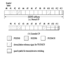
- the 3GPP LTE standard supports a type 1 radio frame structure applicable to frequency division duplex (FDD) and a type 2 radio frame structure applicable to time division duplex (TDD).
- the downlink radio frame consists of 10 subframes, and one subframe consists of two slots in the time domain.
- the time it takes for one subframe to be transmitted is called a transmission time interval (TTI).
- TTI transmission time interval
- one subframe may have a length of 1 ms and one slot may have a length of 0.5 ms.
- One slot includes a plurality of OFDM symbols in the time domain and a plurality of resource blocks (RBs) in the frequency domain.
- RBs resource blocks
- a resource block (RB) is a resource allocation unit and may include a plurality of consecutive subcarriers in one block.
- the number of OFDM symbols included in one slot may vary depending on the configuration of a cyclic prefix (CP).
- CP has an extended CP (normal CP) and a normal CP (normal CP).
- normal CP normal CP
- the number of OFDM symbols included in one slot may be seven.
- the OFDM symbol is configured by an extended CP, since the length of one OFDM symbol is increased, the number of OFDM symbols included in one slot is smaller than that of the normal CP.
- the number of OFDM symbols included in one slot may be six. If the channel state is unstable, such as when the terminal moves at a high speed, an extended CP may be used to further reduce intersymbol interference.
- one subframe includes 14 OFDM symbols.
- the first two or three OFDM symbols of each subframe may be allocated to a physical downlink control channel (PDCCH), and the remaining OFDM symbols may be allocated to a physical downlink shared channel (PDSCH).
- PDCCH physical downlink control channel
- PDSCH physical downlink shared channel
- Type 2 radio frames consist of two half frames, each of which has five subframes, a downlink pilot time slot (DwPTS), a guard period (GP), and an uplink pilot time slot (UpPTS).
- DwPTS downlink pilot time slot
- GP guard period
- UpPTS uplink pilot time slot
- One subframe consists of two slots.
- DwPTS is used for initial cell search, synchronization or channel estimation at the terminal.
- UpPTS is used for channel estimation at the base station and synchronization of uplink transmission of the terminal.
- the guard period is a period for removing interference generated in the uplink due to the multipath delay of the downlink signal between the uplink and the downlink.
- one subframe consists of two slots regardless of the radio frame type.
- the structure of the radio frame is only an example, and the number of subframes included in the radio frame or the number of slots included in the subframe and the number of symbols included in the slot may be variously changed.
- FIG. 2 is a diagram illustrating a resource grid in a downlink slot.
- One downlink slot includes seven OFDM symbols in the time domain and one resource block (RB) is shown to include 12 subcarriers in the frequency domain, but the present invention is not limited thereto.
- one slot includes 7 OFDM symbols in the case of a general cyclic prefix (CP), but one slot may include 6 OFDM symbols in the case of an extended-CP (CP).
- Each element on the resource grid is called a resource element.
- One resource block includes 12 ⁇ 7 resource elements.
- the number N DL of resource blocks included in the downlink slot depends on the downlink transmission bandwidth.
- the structure of the uplink slot may be the same as the structure of the downlink slot.
- FIG. 3 is a diagram illustrating a structure of a downlink subframe.
- Up to three OFDM symbols at the front of the first slot in one subframe correspond to a control region to which a control channel is allocated.
- the remaining OFDM symbols correspond to data regions to which a Physical Downlink Shared Channel (PDSCH) is allocated.
- Downlink control channels used in the 3GPP LTE / LTE-A system include, for example, a Physical Control Format Indicator Channel (PCFICH), a Physical Downlink Control Channel (PDCCH), Physical Hybrid Automatic Repeat Request Indicator Channel (PHICH).
- PCFICH Physical Control Format Indicator Channel
- PDCH Physical Downlink Control Channel
- PHICH Physical Hybrid Automatic Repeat Request Indicator Channel
- the PHICH includes a HARQ ACK / NACK signal as a response of uplink transmission.
- Control information transmitted through the PDCCH is referred to as downlink control information (DCI).
- the DCI includes uplink or downlink scheduling information or an uplink transmit power control command for a certain terminal group.
- the PDCCH is a resource allocation and transmission format of the downlink shared channel (DL-SCH), resource allocation information of the uplink shared channel (UL-SCH), paging information of the paging channel (PCH), system information on the DL-SCH, on the PDSCH Resource allocation of upper layer control messages such as random access responses transmitted to the network, a set of transmit power control commands for individual terminals in an arbitrary terminal group, transmission power control information, and activation of voice over IP (VoIP) And the like.
- a plurality of PDCCHs may be transmitted in the control region.
- the terminal may monitor the plurality of PDCCHs.
- the PDCCH is transmitted in an aggregation of one or more consecutive Control Channel Elements (CCEs).
- CCEs Control Channel Elements
- CCE is a logical allocation unit used to provide a PDCCH at a coding rate based on the state of a radio channel.
- the CCE corresponds to a plurality of resource element groups.
- the number of CCEs required for the PDCCH may vary depending on the size and coding rate of the DCI. For example, any one of 1, 2, 4, and 8 CCEs (corresponding to PDCCH formats 0, 1, 2, and 3, respectively) may be used for PDCCH transmission, and when the size of DCI is large and / or channel state If a low coding rate is required due to poor quality, a relatively large number of CCEs may be used for one PDCCH transmission.
- the base station determines the PDCCH format in consideration of the size of the DCI transmitted to the terminal, the cell bandwidth, the number of downlink antenna ports, the PHICH resource amount, and adds a cyclic redundancy check (CRC) to the control information.
- the CRC is masked with an identifier called a Radio Network Temporary Identifier (RNTI) according to the owner or purpose of the PDCCH.
- RNTI Radio Network Temporary Identifier
- the PDCCH is for a specific terminal, the cell-RNTI (C-RNTI) identifier of the terminal may be masked to the CRC.
- a paging indicator identifier P-RNTI
- SI-RNTI system information identifier and system information RNTI
- RA-RNTI Random Access-RNTI
- the uplink subframe may be divided into a control region and a data region in the frequency domain.
- a physical uplink control channel (PUCCH) including uplink control information is allocated to the control region.
- a physical uplink shared channel (PUSCH) including user data is allocated.
- PUCCH physical uplink control channel
- PUSCH physical uplink shared channel
- one UE does not simultaneously transmit a PUCCH and a PUSCH.
- PUCCH for one UE is allocated to an RB pair in a subframe. Resource blocks belonging to a resource block pair occupy different subcarriers for two slots. This is called a resource block pair allocated to the PUCCH is frequency-hopped at the slot boundary.
- the transmitted packet is transmitted through a wireless channel
- signal distortion may occur during the transmission process.
- the distortion In order to correctly receive the distorted signal at the receiving end, the distortion must be corrected in the received signal using the channel information.
- a method of transmitting the signal known to both the transmitting side and the receiving side and finding the channel information with the distortion degree when the signal is received through the channel is mainly used.
- the signal is called a pilot signal or a reference signal.
- the reference signal may be divided into an uplink reference signal and a downlink reference signal.
- an uplink reference signal as an uplink reference signal,
- DM-RS Demodulation-Reference Signal
- SRS sounding reference signal
- DM-RS Demodulation-Reference Signal
- CSI-RS Channel State Information Reference Signal
- MBSFN Multimedia Broadcast Single Frequency Network
- Reference signals can be classified into two types according to their purpose. There is a reference signal for obtaining channel information and a reference signal used for data demodulation. Since the former has a purpose for the UE to acquire channel information on the downlink, the UE should be transmitted over a wide band, and the UE should receive the reference signal even if the UE does not receive the downlink data in a specific subframe. It is also used in situations such as handover.
- the latter is a reference signal transmitted together with a corresponding resource when the base station transmits a downlink, and the terminal can demodulate data by performing channel measurement by receiving the reference signal. This reference signal should be transmitted in the area where data is transmitted.
- FIG. 5 is a configuration diagram of a wireless communication system having multiple antennas.
- the transmission rate can be improved and the frequency efficiency can be significantly improved.
- the transmission rate may theoretically increase as the rate of increase rate Ri multiplied by the maximum transmission rate Ro when using a single antenna.
- a transmission rate four times higher than a single antenna system may be theoretically obtained. Since the theoretical capacity increase of multi-antenna systems was proved in the mid 90's, various techniques to actively lead to the actual data rate improvement have been actively studied. In addition, some technologies are already being reflected in various wireless communication standards such as 3G mobile communication and next generation WLAN.
- the research trends related to multi-antennas to date include the study of information theory aspects related to the calculation of multi-antenna communication capacity in various channel environments and multi-access environments, the study of wireless channel measurement and model derivation of multi-antenna systems, improvement of transmission reliability, and improvement of transmission rate. Research is being actively conducted from various viewpoints, such as research on space-time signal processing technology.
- the communication method in a multi-antenna system will be described in more detail using mathematical modeling. It is assumed that there are Nt transmit antennas and Nt receive antennas in the system.
- the transmission signal when there are Nt transmit antennas, the maximum information that can be transmitted is NT.
- the transmission information may be expressed as follows.
- Each transmission information The transmit power may be different.
- Each transmit power In this case, the transmission information whose transmission power is adjusted may be expressed as follows.
- Weighting matrix Nt transmitted signals actually applied by applying Consider the case where is configured.
- Weighting matrix Plays a role in properly distributing transmission information to each antenna according to a transmission channel situation.
- Vector It can be expressed as follows.
- Received signal is received signal of each antenna when there are Nr receiving antennas Can be expressed as a vector as
- channels may be divided according to transmit / receive antenna indexes. From the transmit antenna j to the channel through the receive antenna i It is indicated by. Note that in the order of the index, the receiving antenna index is first, and the index of the transmitting antenna is later.
- FIG. 5 (b) shows a channel from NR transmit antennas to receive antenna i .
- the channels may be bundled and displayed in vector and matrix form.
- a channel arriving from a total of NT transmit antennas to a receive antenna i may be represented as follows.
- AWGN Additive White Gaussian Noise
- the received signal may be expressed as follows through the above-described mathematical modeling.
- the channel matrix indicating the channel state The number of rows and columns of is determined by the number of transmit and receive antennas.
- Channel matrix The number of rows is equal to the number of receiving antennas NR, and the number of columns is equal to the number of transmitting antennas Nt. That is, the channel matrix The matrix is NR ⁇ Nt.
- the rank of a matrix is defined as the minimum number of rows or columns that are independent of each other. Thus, the rank of the matrix cannot be greater than the number of rows or columns.
- Channel matrix Rank of ( ) Is limited to
- rank may be defined as the number of nonzero eigenvalues when the matrix is eigenvalue decomposition.
- another definition of rank may be defined as the number of nonzero singular values when singular value decomposition is performed.
- rank in the channel matrix The physical meaning of is the maximum number of different information that can be sent on a given channel.
- 'rank' for MIMO transmission refers to the number of paths that can independently transmit signals at specific time points and specific frequency resources, and 'number of layers' denotes each path. It indicates the number of signal streams transmitted through the system. In general, since the transmitting end transmits the number of layers corresponding to the number of ranks used for signal transmission, unless otherwise specified, the rank has the same meaning as the number of layers.
- some nodes may transmit a D2D signal (where the node may be referred to as an eNB, a UE, a synchronization reference node or a synchronization source), and transmit a D2D synchronization signal (D2DSS, D2D Synchronization Signal).
- a method of transmitting and receiving signals in synchronization with the remaining terminals may be used.
- the D2D synchronization signal may be a primary synchronization signal (Primary D2DSS or Primary Sidelink synchronization signal (PSSS)) or a secondary synchronization signal (SD2DSS (Secondary D2DSS or Secondary Sidelink synchronization signal)). It may be a Zadoff-chu sequence or a similar / modified / repeated structure to the PSS, etc. It is also possible to use other Zadoff Chu root indices (eg, 26, 37) unlike the DL PSS. May be a similar / modified / repeated structure to M-sequence or SSS, etc.
- PD2DSS Physical D2D synchronization channel
- SRN becomes eNB
- D2DSS becomes PSS / SSS
- PD2DSS The / SD2DSS follows the UL subcarrier mapping scheme, and the subframe through which the D2D synchronization signal is transmitted is shown in Fig. 6.
- the PD2DSCH Physical D2D synchronization channel
- the PD2DSCH may be transmitted on the same subframe as the D2DSS or on a subsequent subframe DMRS may be used for demodulation of the PD2DSCH.
- the SRN may be a node transmitting a D2DSS and a Physical D2D Synchronization Channel (PD2DSCH).
- the D2DSS may be in the form of a specific sequence
- the PD2DSCH may be in the form of a sequence representing specific information or a code word after a predetermined channel coding.
- the SRN may be an eNB or a specific D2D terminal.
- the UE may be an SRN.
- the D2DSS may be relayed for D2D communication with an out of coverage terminal.
- the D2DSS can be relayed over multiple hops.
- relaying a synchronization signal is a concept including not only directly relaying a synchronization signal of a base station, but also transmitting a D2D synchronization signal of a separate format in accordance with the timing of receiving the synchronization signal. As such, since the D2D synchronization signal is relayed, the in-coverage terminal and the out-of-coverage terminal can directly perform communication.
- a UE refers to a network equipment such as a base station for transmitting and receiving a signal according to a terminal or a D2D communication scheme.
- the terminal may select a resource unit corresponding to a specific resource in a resource pool representing a set of resources and transmit a D2D signal using the corresponding resource unit.
- the receiving terminal UE2 may be configured with a resource pool in which UE1 can transmit a signal, and detect a signal of UE1 in the corresponding pool.
- the resource pool may be notified by the base station when UE1 is in the connection range of the base station.
- a resource pool is composed of a plurality of resource units, each terminal may select one or a plurality of resource units and use them for transmitting their D2D signals.
- the resource unit may be as illustrated in FIG. 8 (b). Referring to FIG. 8 (b), it can be seen that total frequency resources are divided into NFs and total time resources are divided into NTs so that a total of NF * NT resource units are defined.
- the resource pool may be repeated every NT subframe. In particular, one resource unit may appear periodically and repeatedly as shown.
- a resource pool may mean a set of resource units that can be used for transmission by a terminal that wants to transmit a D2D signal.
- Resource pools can be divided into several types. First, they may be classified according to contents of D2D signals transmitted from each resource pool. For example, the contents of the D2D signal may be divided, and a separate resource pool may be configured for each.
- As the content of the D2D signal there may be a scheduling assignment (SA), a D2D data channel, and a discovery channel (SA), where the location of a resource used for transmission of a subsequent D2D data channel by a transmitting terminal and others It may be a signal including information such as a modulation and coding scheme (MCS), a MIMO transmission scheme, a timing advance (TA), etc. required for demodulation of a data channel, which may be multiplexed and transmitted together with D2D data on the same resource unit.
- MCS modulation and coding scheme
- TA timing advance
- the SA resource pool may mean a pool of resources in which the SA is multiplexed with the D2D data and transmitted, or may be referred to as a D2D control channel or a physical sidelink control channel (PSCCH).
- the D2D data channel (or physical sidelink shared channel (PSSCH)) may be a pool of resources used by a transmitting terminal to transmit user data. If the SA is multiplexed and transmitted together with the D2D data on the same resource unit, only the D2D data channel except for the SA information may be transmitted in the resource pool for the D2D data channel, that is, individual resource units in the SA resource pool.
- the REs used to transmit SA information on the D2D data channel resource pool can still be used to transmit D2D data in the discovery channel, where a transmitting terminal transmits information such as its own ID and the like so that a neighboring terminal can discover itself. It can be a resource pool for messages to be made.
- the transmission timing determination method of the D2D signal for example, is it transmitted at the time of reception of a synchronization reference signal or is transmitted by applying a constant TA there
- a resource allocation method for example, For example, whether an eNB assigns transmission resources of an individual signal to an individual transmitting UE or whether an individual transmitting UE selects an individual signaling resource on its own in a pool, and a signal format (for example, each D2D signal occupies one subframe).
- the number of symbols, the number of subframes used for transmission of one D2D signal), the signal strength from the eNB, and the transmission power strength of the D2D UE may be further divided into different resource pools.
- Mode 1 a transmission resource region is set in advance, or the eNB designates a transmission resource region, and the UE directly selects a transmission resource in a method of directly instructing the eNB to transmit resources of the D2D transmitting UE in D2D communication.
- Mode 2 In the case of D2D discovery, when the eNB directly indicates a resource, a type 2 when a UE directly selects a transmission resource in a preset resource region or a resource region indicated by the eNB is called Type 1.
- the mode 1 terminal may transmit an SA (or a D2D control signal, Sidelink Control Information (SCI)) through a resource configured from the base station.
- SA or a D2D control signal, Sidelink Control Information (SCI)
- SCI Sidelink Control Information
- the mode 2 terminal is configured with a resource to be used for D2D transmission from the base station.
- the SA may be transmitted by selecting a time frequency resource from the configured resource.
- the first SA period may be started in a subframe away from a specific system frame by a predetermined offset SAOffsetIndicator indicated by higher layer signaling.
- Each SA period may include a SA resource pool and a subframe pool for D2D data transmission.
- the SA resource pool may include the last subframe of the subframes indicated by which the SA is transmitted in the subframe bitmap (saSubframeBitmap) from the first subframe of the SA period.
- a sub-frame used for actual data transmission may be determined by applying time-resource pattern for transmission (T-RPT).
- the T-RPT may be repeatedly applied, and the last applied T-RPT is the number of remaining subframes. As many as truncated can be applied.
- the SA may indicate the transmission location of the data in the form of T-RPT or in another explicit way. For example, it may be in the form of indicating the transmission start position of the data, the number of repetitions and the like. More generally, SA is a channel indicating time and frequency positions of data transmission resources and including additional information necessary for data decoding.
- the SA resource pool may be separated from the data pool, but may be partially overlapped with the data pool to use some data areas together. In addition, the data pool and the SA resource pool may not be separated in the time domain but may be separated in the frequency domain.
- an immediate acknowledgment can be used to measure the RTT.
- One STA may measure RTT by measuring a time point for receiving ACK after transmitting unicast data to an AP.
- the RTT may be measured by measuring a time point for transmitting a request to send (RTS) and receiving a clear to send (CTS).
- RTS request to send
- CTS clear to send
- Embodiment 1 relates to a method of estimating distance and measuring RTT when assuming that a first terminal UE A and a second terminal UE B are spaced apart from each other as illustrated in FIG. 10.
- the first terminal may transmit a D2D signal in subframe N. Thereafter, the D2D signal may be received in the subframe N + K from the second terminal having the time point at which the D2D signal is received as the subframe boundary.
- K may be a value predetermined or signaled by the network.
- the first terminal may measure a reception time of the D2D signal transmitted by the second terminal to measure a round trip time (RTT). That is, among two D2D capable terminals, UE A transmits a D2D signal, and UE B sets a time point at which the UE A signal is received as a subframe boundary, and then transmits a D2D signal in a promised subframe.
- RTT round trip time
- UE A may perform ranging by detecting a signal reception time of UE B in a promised subframe and measuring round trip time (RTT).
- RTT round trip time
- the RTT may be obtained by dividing the difference between the reception time of the D2D signal transmitted by the second terminal and the start point of the N + K subframe by the electromagnetic wave speed.
- the D2D signal transmitted by the first terminal in subframe N may be one of a discovery signal, a D2D communication signal, and a sidelink synchronization signal (SLSS).
- SLSS sidelink synchronization signal
- the second terminal sets the SLSS reception time as a subframe boundary to transmit a signal.
- the DL timing is not set to the subframe boundary but also the SLSS reception time is set to the subframe boundary in the in coverage to transmit the signal.
- the signal transmitted by the first terminal is referred to as a D2D signal, but may be one of existing UL signals instead of the D2D signal. That is, it may be a signal in the form of a sequence such as DMRS or SRS, or may be a signal in the form of a data packet such as a PUSCH or a sidelink discovery / communication (shared) channel.
- the signal returned by the second terminal may be one of existing UL signals or may be a sidelink (eg, D2D) signal.
- the UL signal may be a signal in the form of a sequence such as DMRS or SRS, or may be a signal in the form of a data packet such as a PUSCH.
- the sidelink signal may be a sidelink synchronization signal (SLSS), a discovery signal, or a signal of the same type as or similar to a D2D communication signal.
- the (D2D) signal transmitted by the second terminal may include location information of the first terminal, and the location information of the first terminal may include one or more of latitude, longitude, and height. It may include. In this case, the first terminal measures the RTT and at the same time, the second terminal is able to know the approximate radius of the absolute position.
- the location information may be separately transmitted by the second terminal in the ranging process.
- the first terminal since the second terminal receiving the signal transmitted by the first terminal transmits a signal based on this, the first terminal estimates the timing of the signal returned based on the timing at which the first terminal transmits the signal.
- the transmission of the first signal for ranging may use any timing.
- the D2D signal may be transmitted using DL timing or UL timing.
- the UE B may transmit a reply signal for the D2D signal of the UE A in the subframe promised based on the detection time point.
- FIG. 11 illustrates signal transmission and reception and RTT measurement between the first terminal UE A and the second terminal UE B.
- N, K may be predetermined, or at least one of N, K may be configured by a network.
- N and K may be configured as separate resources for sidelink (between UE) ranging (to a UE to transmit and receive ranging signals as physical layer or higher layer signals by a network) or may be predetermined values.
- one of N and K may be configured by a network, and the other may use a predetermined value.
- K may be equal to or greater than a (a may be predetermined or configured by the network), and a rule may be determined to transmit in the nearest subframe included in the D2D resource. That is, K is a value configured by the network, and when the subframe N + K is not a D2D subframe, it may be the nearest D2D subframe in the subframe N + K (greater than N + K).
- K may be predetermined from a value greater than or equal to and less than or equal to b, or may be signaled by the network.
- the upper limit b is set because when the second terminal receives the first terminal signal and returns a signal after too much time, the position of the second terminal and / or the first terminal is changed to estimate an incorrect RTT. to be.
- resource allocation associated with discovery may be made.
- X subframes may be configured or preconfigured by the network for D2D ranging.
- the sidelink resources related to such ranging are composed of physical layer or higher layer signals by the network, or transmitting and receiving ranging purpose signals from predetermined resources (when some or all of the UEs are out-of-coverage). can do.
- the terminal to perform ranging may signal a location of a resource used for ranging to the ranging signal receiving terminal through a D2D control signal.
- the terminal that sent the first ranging signal may instruct the receiving terminal to perform ranging using the corresponding packet and transmit feedback on the ranging signal on a specific resource.
- Embodiment 2 relates to a case where a time point at which a first terminal transmits a signal for ranging is set to a third timing instead of a DL timing or a PUSCH timing of a base station.
- the third timing may be an intermediate value between the DL timing and the UL timing or a timing at which an TA / 2 offset is applied from the DL timing, or a global timing such as GPS.
- an additional 624Ts offset may be applied in TDD for Tx / Rx switching.
- it can be expressed by transmitting a signal at the DL Tx timing of the base station, which will be referred to as DL Tx timing.
- all the UEs transmit the signals by arranging the transmission timings in the DL transmission timing, and the second terminal (the UE receiving the ranging signal) receives the first DL from the time point of its DL or UL timing or TA / 2.
- the propagation delay between UEs is estimated by detecting the time at which the signal of the terminal is received. This method may be efficient in terms of resource utilization since the second terminal does not have to return a signal.
- the first terminal and the second terminal may receive a GPS signal and have a common timing clock to transmit signals based on the same timing.
- very small values of timing measurement errors can cause large errors in the position estimation, so it is necessary to correct the errors as much as possible. For example, referring to FIG. 12, assume that a first terminal has an error of a and a second terminal has an error of an absolute time reference of b or an error from GPS timing.
- the first terminal when the first terminal receives the signal of the second terminal, it measures d + (b-a), and when the second terminal receives the signal of the first terminal, the value of d- (b-a) is measured.
- d means propagation delay between the first terminal and the B.
- each terminal when the first terminal and the B signal the measurement values of the propagation delays that estimate each other's propagation delays to each other through a discovery or communication signal, each terminal averages its own measurement values and those of the other terminals. Accurate d can be estimated.
- each terminal may signal all or a part of the measurement value of the propagation delay from the other terminal and information indicating the ID of the terminal or the other terminal found by the other terminal to the other terminal through the D2D signal. . It is possible to reduce the clock error between two terminals by averaging each terminal's own measurement value and the measured signal signaled from another terminal.
- the first terminal measures d + (b-a) and signals it to the second terminal
- the second terminal measures d- (b-a) and signals it to the first terminal.
- Each UE may calculate an accurate d by averaging the value measured by the UE and the value received from the counterpart terminal.
- the location of the D2D signal or UL signal and the transmission resource transmitted by the first terminal for ranging may be indicated by the base station through a dedicated signal, and each UE selects a transmission resource in a resource region allocated for several UE groups.
- a resource for a signal transmitted by a specific UE or a UE group may be configured or preconfigured by the network.
- the second terminal may transmit the estimated propagation delay or the RTT or other types of information capable of inferring a distance between the two UEs or an equivalent thereof to the first terminal as a physical layer or a higher layer signal to the first terminal.
- the first terminal can also estimate the distance between two UEs by measuring the signal transmitted by the second terminal at the DL TX timing.
- the timing for transmitting the ranging signal may be set using a value obtained by averaging the DL / UL or DL Tx timings from the base station.
- a rule may be determined to average only timings of signals (from a base station) whose signal strength is greater than or equal to a predetermined threshold from the base station, and a threshold for determining signal strength from the base station participating in the timing setting may be predetermined or may be determined in advance. It may be a value configured by.
- a rule is determined to transmit the signal at a different timing and a separate resource pool.
- the pool may be configured by the network with physical or higher layer signals. (preconfigured resources for out coverage)
- a resource for transmitting and receiving a signal for ranging (in other words, a resource for transmitting (or receiving) a signal at a third timing other than UL and DL timing) may be transmitted at a period similar to discovery, and the network may be a discovery resource.
- additional signaling may occur or rules may be set to be sent in a predetermined portion of the discovery resource pool.
- a resource for measuring a reception point of a ranging or other terminal signal may be transmitted in the form of 'scheduling assignment + data', in which the SA is used for ranging or positioning to distinguish it from other D2D communication purposes.
- Transmission and reception may be performed by setting a format or SA ID.
- the different SA format includes different field configurations of the SA and different physical SA formats.
- terminals that perform ranging by transmitting a signal having a predetermined sequence or 'sequence + codeword' type may exchange signals with each other.
- the SA may be transmitted by a terminal to perform ranging, and at this time, the ID included in the SA may be transmitted as an ID that can be recognized by the receiving terminal in advance.
- a resource transmitted by the terminal transmitting the SA and a resource region transmitted by the terminal receiving the SA may be divided.
- a transmitting terminal transmits a signal for ranging or positioning at an even number 1 position, and at an odd number 1 position, a receiving terminal transmits a ranging or It can transmit a signal for positioning purposes.
- a resource region (resource pool) in which a transmitting terminal and a receiving terminal or terminals A and B to perform ranging transmit a signal for ranging or positioning to a counterpart terminal by a network or are divided in advance, Can signal each other.
- the timing of transmitting SA and the timing of transmitting data may be different.
- transmission is performed at DL timing
- transmission is performed at DL timing
- Examples 1 and 2 Either one of the described timing setting methods (based on timing of receiving a signal from another UE or offsetting by TA / 2 from DL (Rx) timing based on timing information from a third device (e.g., GPS) or In the applied timing (DL Tx timing), a signal may be transmitted in one way, and in the SA, an offset value between timing of transmitting SA and timing of transmitting data may be transmitted as one of the contents of the SA.
- the BW of the signal for ranging or positioning may be predetermined or configured by the network. For accurate timing estimation, it is desirable to transmit the signal in the wideband as much as possible. Less transmission) may be excluded from the signal transmission BW for positioning purposes.
- a rule may be determined to transmit over a minimum NRB (N is a predetermined value or a value set by a network), and in some cases, a transmitting terminal may select from a signal of 6 RB or more and 100 RB or less and instruct it through SA .
- the sequence used for ranging or positioning may be similar to DMRS, may be in the form of PSS / SSS, or may be in the form of SLSS (PSSS / SSSS) or a modified form thereof.
- the data area can be emptied or the data area can be filled with RS and transmitted (that is, all existing codeword transmission positions are also transmitted with RS) or RSs can only be transmitted from existing RS transmission positions and data RE It can also be sent in an empty form.
- RS for timing / positioning purpose may be transmitted to a last symbol of a subframe not used by existing D2D UEs. In this case, some symbols or all of the next subframe may be set as puncturing or guard regions.
- the D2D signal is a D2D when DL timing is used.
- the symbol boundary of the signal and the ranging signal may overlap.
- a ranging signal having a partial symbol length may be transmitted.
- a symbol of half length of an existing symbol may be transmitted in the last symbol region of a D2D subframe.
- the short ranging signal can be used to prevent the D2D symbol boundary and the ranging symbol boundary from overlapping each other.
- one terminal may be a base station and may signal its location information to the terminal as a physical layer or a higher layer signal for ranging purpose between the base station and the terminal. If the terminal is a terminal having a GPS, or a terminal that knows its position using another position estimation technique, the distance between the base station and the terminal is determined by comparing its position with the position of the base station, and at this time, receiving the base station signal The transmission time of the base station can be estimated using the viewpoint.
- the terminal Upon knowing the transmission time information of the base station, the terminal aligns the transmission time information of the signal with the transmission time information of the base station and transmits a specific signal, which facilitates ranging / positioning or D2D communication between the terminal and the terminal.
- the receiving terminal may be used to determine the beamforming direction by using a method in which the terminal or the base station transmits its location information to the neighboring terminal as a physical layer or a higher layer signal. For example, when the first device transmits its location information, the second device receives the location information, and the second device grasps its location and the location of the first device and performs beamforming in the direction of the first device. Can be. Especially in mmwave, it is very important to find the correct beam direction through the initial beam search process.
- each terminal or the base station may be separately set, and each base station or the terminal may periodically or aperiodically set its own location information in a resource set in advance or set by a network. Send.
- FIG. 13 is a diagram showing the configuration of a transmission point apparatus and a terminal apparatus according to an embodiment of the present invention.
- the transmission point apparatus 10 may include a receiver 11, a transmitter 12, a processor 13, a memory 14, and a plurality of antennas 15. .
- the plurality of antennas 15 refers to a transmission point apparatus that supports MIMO transmission and reception.
- the reception device 11 may receive various signals, data, and information on the uplink from the terminal.
- the transmitter 12 may transmit various signals, data, and information on downlink to the terminal.
- the processor 13 may control the overall operation of the transmission point apparatus 10.
- the processor 13 of the transmission point apparatus 10 may process matters necessary in the above-described embodiments.
- the processor 13 of the transmission point apparatus 10 performs a function of processing the information received by the transmission point apparatus 10, information to be transmitted to the outside, and the memory 14 stores the calculated information and the like. It may be stored for a predetermined time and may be replaced by a component such as a buffer (not shown).
- the terminal device 20 may include a receiver 21, a transmitter 22, a processor 23, a memory 24, and a plurality of antennas 25. have.
- the plurality of antennas 25 refers to a terminal device that supports MIMO transmission and reception.
- the receiving device 21 may receive various signals, data, and information on downlink from the base station.
- the transmitter 22 may transmit various signals, data, and information on the uplink to the base station.
- the processor 23 may control operations of the entire terminal device 20.
- the processor 23 of the terminal device 20 may process matters necessary in the above-described embodiments.
- the processor 23 of the terminal device 20 performs a function of processing the information received by the terminal device 20, information to be transmitted to the outside, etc., and the memory 24 stores the calculated information and the like for a predetermined time. And may be replaced by a component such as a buffer (not shown).
- the description of the transmission point apparatus 10 may be equally applicable to a relay apparatus as a downlink transmission entity or an uplink reception entity, and the description of the terminal device 20 is a downlink. The same may be applied to the relay apparatus as the receiving subject or the uplink transmitting subject.
- Embodiments of the present invention described above may be implemented through various means.
- embodiments of the present invention may be implemented by hardware, firmware, software, or a combination thereof.
- a method according to embodiments of the present invention may include one or more Application Specific Integrated Circuits (ASICs), Digital Signal Processors (DSPs), Digital Signal Processing Devices (DSPDs), and Programmable Logic Devices (PLDs). It may be implemented by field programmable gate arrays (FPGAs), processors, controllers, microcontrollers, microprocessors, and the like.
- ASICs Application Specific Integrated Circuits
- DSPs Digital Signal Processors
- DSPDs Digital Signal Processing Devices
- PLDs Programmable Logic Devices
- FPGAs field programmable gate arrays
- processors controllers, microcontrollers, microprocessors, and the like.
- the method according to the embodiments of the present invention may be implemented in the form of a module, a procedure, or a function that performs the functions or operations described above.
- the software code may be stored in a memory unit and driven by a processor.
- the memory unit may be located inside or outside the processor, and may exchange data with the processor by various known means.
- Embodiments of the present invention as described above may be applied to various mobile communication systems.
Abstract
Un mode de réalisation de la présente invention concerne un procédé au moyen duquel un équipement utilisateur (UE) effectue une télémétrie dans un système de communication sans fil, ce procédé comprenant les étapes consistant à: transmettre un signal de dispositif à dispositif (D2D) dans une sous-trame N par un premier UE; recevoir le signal D2D dans une sous-trame N + K d'un second UE, qui a défini, en tant que limite de sous-trame, un point temporel au niveau duquel le signal D2D est reçu; et mesurer, à l'aide du premier UE, un temps aller-retour (RTT) par détection d'un point temporel de réception du signal D2D transmis par le second UE.
Priority Applications (3)
| Application Number | Priority Date | Filing Date | Title |
|---|---|---|---|
| US15/563,530 US10568057B2 (en) | 2015-04-01 | 2016-04-01 | Method for performing ranging related operation in wireless communication system |
| CN201680019836.3A CN107439033B (zh) | 2015-04-01 | 2016-04-01 | 无线通信系统中执行测距有关的操作的方法 |
| EP16773497.9A EP3280200B1 (fr) | 2015-04-01 | 2016-04-01 | Procédé d'exécution d'une opération relative à la télémétrie dans un système de communication sans fil |
Applications Claiming Priority (6)
| Application Number | Priority Date | Filing Date | Title |
|---|---|---|---|
| US201562141841P | 2015-04-01 | 2015-04-01 | |
| US62/141,841 | 2015-04-01 | ||
| US201562204430P | 2015-08-12 | 2015-08-12 | |
| US62/204,430 | 2015-08-12 | ||
| US201562251669P | 2015-11-05 | 2015-11-05 | |
| US62/251,669 | 2015-11-05 |
Publications (1)
| Publication Number | Publication Date |
|---|---|
| WO2016159716A1 true WO2016159716A1 (fr) | 2016-10-06 |
Family
ID=57006433
Family Applications (1)
| Application Number | Title | Priority Date | Filing Date |
|---|---|---|---|
| PCT/KR2016/003406 WO2016159716A1 (fr) | 2015-04-01 | 2016-04-01 | Procédé d'exécution d'une opération relative à la télémétrie dans un système de communication sans fil |
Country Status (4)
| Country | Link |
|---|---|
| US (1) | US10568057B2 (fr) |
| EP (1) | EP3280200B1 (fr) |
| CN (1) | CN107439033B (fr) |
| WO (1) | WO2016159716A1 (fr) |
Cited By (2)
| Publication number | Priority date | Publication date | Assignee | Title |
|---|---|---|---|---|
| US10321401B2 (en) | 2016-08-12 | 2019-06-11 | Qualcomm Incorporated | Clear-to-send (CTS) power control in sidelink |
| US10716084B2 (en) | 2016-05-18 | 2020-07-14 | Qualcomm Incorporated | Narrowband positioning signal design and procedures |
Families Citing this family (25)
| Publication number | Priority date | Publication date | Assignee | Title |
|---|---|---|---|---|
| US10447426B2 (en) * | 2015-12-04 | 2019-10-15 | Qualcomm Incorporated | Scheduling based on end-to-end delay bound |
| EP3487103B1 (fr) * | 2016-08-11 | 2021-07-07 | Huawei Technologies Co., Ltd. | Procédé, dispositif et système de transmission d'informations d'attribution de programmation |
| US10281589B2 (en) * | 2016-08-29 | 2019-05-07 | International Business Machines Corporation | Dynamic GPS location update |
| US10317236B2 (en) | 2016-08-29 | 2019-06-11 | International Business Machines Corporation | Dynamic GPS location update |
| DE102017203905B4 (de) * | 2016-12-22 | 2022-11-10 | Volkswagen Aktiengesellschaft | Verfahren zur Organisation der Kommunikation zwischen Mobilfunknetz-Teilnehmerstationen in einer Mobilfunkzelle, sowie Mobilfunknetz-Teilnehmerstation und Mobilfunknetz-Verwaltungseinheit bei der Verwendung des erfindungsgemäßen Verfahrens |
| US11202326B2 (en) * | 2016-12-29 | 2021-12-14 | Koninklijke Philips N.V. | Wireless communication system |
| US11388026B2 (en) * | 2017-09-28 | 2022-07-12 | Lenovo (Beijing) Limited | Method and apparatus for sounding reference signal transmission on sidelink |
| EP3756387B1 (fr) * | 2018-02-19 | 2022-11-09 | Fraunhofer-Gesellschaft zur Förderung der angewandten Forschung e.V. | Plage de liaison secondaire |
| US20190320358A1 (en) * | 2018-04-17 | 2019-10-17 | Qualcomm Incorporated | User equipment power optimization in millimeter wave access networks |
| JP7379328B2 (ja) * | 2018-04-17 | 2023-11-14 | 株式会社Nttドコモ | 端末、無線通信方法、基地局及びシステム |
| US11064510B2 (en) * | 2018-05-30 | 2021-07-13 | Qualcomm Incorporated | Ranging between a user equipment and a fixed reference node |
| US11751159B2 (en) | 2018-05-30 | 2023-09-05 | Qualcomm Incorporated | Ranging between a user equipment and a fixed reference node |
| CN110768771B (zh) * | 2018-07-27 | 2021-07-27 | 维沃移动通信有限公司 | 同步信号传输方法及终端 |
| KR20200127402A (ko) * | 2019-05-02 | 2020-11-11 | 삼성전자주식회사 | 단말 직접 통신시스템에서 패킷 송수신 영역 결정 방법 및 장치 |
| US11425531B2 (en) | 2019-11-06 | 2022-08-23 | Huawei Technologies Co., Ltd. | Connectivity-based positioning determination in wireless communication networks |
| CN114902700A (zh) * | 2020-01-21 | 2022-08-12 | 联想(北京)有限公司 | 用于无线通信的方法及设备 |
| KR20210106741A (ko) * | 2020-02-21 | 2021-08-31 | 삼성전자주식회사 | 무선 통신 시스템에서 빔 정보 획득 방법 및 장치 |
| WO2021248284A1 (fr) * | 2020-06-08 | 2021-12-16 | 北京小米移动软件有限公司 | Procédé et appareil de détermination de position, ainsi que dispositif de communication et support de stockage |
| CN111869281B (zh) * | 2020-06-11 | 2023-04-04 | 北京小米移动软件有限公司 | 定位测距方法、装置、通信设备及存储介质 |
| WO2022027477A1 (fr) * | 2020-08-06 | 2022-02-10 | 北京小米移动软件有限公司 | Procédé et appareil d'émission et de réception de signal de télémétrie, dispositif et support de stockage lisible |
| JP2023545534A (ja) * | 2020-10-16 | 2023-10-30 | レノボ・(ベイジン)・リミテッド | Nrサイドリンク上のリソースのセットを示すための方法および装置 |
| WO2022217601A1 (fr) * | 2021-04-16 | 2022-10-20 | 北京小米移动软件有限公司 | Procédé et appareil d'attribution de ressources, et support de stockage |
| CN113473626B (zh) * | 2021-07-02 | 2022-11-15 | 上海酷芯微电子有限公司 | 一种无线自组织网络的多用户测距方法及系统 |
| WO2024068621A1 (fr) | 2022-09-27 | 2024-04-04 | Continental Automotive Technologies GmbH | Procédé de positionnement de temps de trajet aller-retour multiple assisté par liaison latérale avec implication de gnb de desserte |
| WO2024068624A1 (fr) | 2022-09-27 | 2024-04-04 | Continental Automotive Technologies GmbH | Procédé de positionnement temporel de trajets aller-retour assisté par liaison latérale sans gnb de desserte |
Citations (4)
| Publication number | Priority date | Publication date | Assignee | Title |
|---|---|---|---|---|
| WO2013162333A1 (fr) * | 2012-04-26 | 2013-10-31 | 한국전자통신연구원 | Procédé de communication entre dispositifs utilisant la commande partielle de dispositifs |
| WO2013165145A1 (fr) * | 2012-04-30 | 2013-11-07 | 한국전자통신연구원 | Procédé et appareil de planification pour une communication de dispositif à dispositif |
| WO2013176999A1 (fr) * | 2012-05-23 | 2013-11-28 | Qualcomm Incorporated | Procédés et appareil de détermination de la distance entre des dispositifs pour une communication entre dispositifs et des services de proximité |
| WO2014165386A2 (fr) * | 2013-04-04 | 2014-10-09 | Blackberry Limited | Procédé et appareil de recherche de proximité pour une communication de dispositif à dispositif |
Family Cites Families (10)
| Publication number | Priority date | Publication date | Assignee | Title |
|---|---|---|---|---|
| EP2514252A1 (fr) * | 2009-12-14 | 2012-10-24 | Nokia Corp. | Appareil et procédé permettant de déterminer l'emplacement de dispositifs de communication sans fil |
| US9820244B2 (en) | 2011-02-11 | 2017-11-14 | Blackberry Limited | Time-advanced random access channel transmission |
| CN103368713B (zh) * | 2012-03-26 | 2017-03-15 | 中兴通讯股份有限公司 | 设备到设备的通信方法及装置 |
| EP3136619B1 (fr) * | 2012-07-13 | 2020-12-30 | Electronics and Telecommunications Research Institute | Procédé de découverte pour communication dispositif à dispositif entre terminaux |
| US9160515B2 (en) * | 2013-04-04 | 2015-10-13 | Intel IP Corporation | User equipment and methods for handover enhancement using scaled time-to-trigger and time-of-stay |
| US20140370904A1 (en) * | 2013-06-12 | 2014-12-18 | Research In Motion Limited | Device-to-device discovery |
| EP3033913B1 (fr) * | 2013-08-12 | 2018-10-31 | Telefonaktiebolaget LM Ericsson (publ) | Positionnement dans une cellule partagée |
| CN104185247B (zh) * | 2013-09-26 | 2017-12-08 | 上海朗帛通信技术有限公司 | Ue装置及方法 |
| KR102236094B1 (ko) * | 2014-04-09 | 2021-04-05 | 삼성전자주식회사 | 셀룰러 통신 시스템에서 셀간 탐색 채널 구간을 정렬하는 장치 및 방법 |
| AU2015386670A1 (en) * | 2015-03-17 | 2017-09-28 | Nokia Technologies Oy | Wireless routing |
-
2016
- 2016-04-01 CN CN201680019836.3A patent/CN107439033B/zh not_active Expired - Fee Related
- 2016-04-01 WO PCT/KR2016/003406 patent/WO2016159716A1/fr active Application Filing
- 2016-04-01 US US15/563,530 patent/US10568057B2/en active Active
- 2016-04-01 EP EP16773497.9A patent/EP3280200B1/fr active Active
Patent Citations (4)
| Publication number | Priority date | Publication date | Assignee | Title |
|---|---|---|---|---|
| WO2013162333A1 (fr) * | 2012-04-26 | 2013-10-31 | 한국전자통신연구원 | Procédé de communication entre dispositifs utilisant la commande partielle de dispositifs |
| WO2013165145A1 (fr) * | 2012-04-30 | 2013-11-07 | 한국전자통신연구원 | Procédé et appareil de planification pour une communication de dispositif à dispositif |
| WO2013176999A1 (fr) * | 2012-05-23 | 2013-11-28 | Qualcomm Incorporated | Procédés et appareil de détermination de la distance entre des dispositifs pour une communication entre dispositifs et des services de proximité |
| WO2014165386A2 (fr) * | 2013-04-04 | 2014-10-09 | Blackberry Limited | Procédé et appareil de recherche de proximité pour une communication de dispositif à dispositif |
Non-Patent Citations (1)
| Title |
|---|
| INTEL CORPORATION: "Synchronization Procedure for D2D Communication", R1-143761, 3GPP TSG RAN WG1 MEETING #78BIS, 27 September 2014 (2014-09-27), Ljubljana, Slovenia, XP050869447 * |
Cited By (2)
| Publication number | Priority date | Publication date | Assignee | Title |
|---|---|---|---|---|
| US10716084B2 (en) | 2016-05-18 | 2020-07-14 | Qualcomm Incorporated | Narrowband positioning signal design and procedures |
| US10321401B2 (en) | 2016-08-12 | 2019-06-11 | Qualcomm Incorporated | Clear-to-send (CTS) power control in sidelink |
Also Published As
| Publication number | Publication date |
|---|---|
| CN107439033A (zh) | 2017-12-05 |
| EP3280200A1 (fr) | 2018-02-07 |
| EP3280200B1 (fr) | 2019-12-11 |
| US10568057B2 (en) | 2020-02-18 |
| EP3280200A4 (fr) | 2018-10-31 |
| US20180098299A1 (en) | 2018-04-05 |
| CN107439033B (zh) | 2020-12-04 |
Similar Documents
| Publication | Publication Date | Title |
|---|---|---|
| WO2016159716A1 (fr) | Procédé d'exécution d'une opération relative à la télémétrie dans un système de communication sans fil | |
| WO2018199652A1 (fr) | Procédé et appareil de réception de signal de réveil dans un système de communications sans fil | |
| WO2016171495A1 (fr) | Procédé et appareil de sélection de relais par terminal de communication de dispositif à dispositif, d'émission ou de réception de signal dans un système de communication sans fil | |
| WO2018038525A1 (fr) | Procédé et dispositif de transmission et de réception de pscch et de pssch par un terminal dans un système de communication sans fil | |
| WO2018203738A1 (fr) | Procédé de commande de puissance d'un signal de liaison latérale par un équipement utilisateur relais dans un système de communication sans fil et appareil associé | |
| WO2017048099A1 (fr) | Procédé et appareil d'émission/réception de messages provenant d'un terminal v2x dans un système de communication sans fil | |
| WO2016159715A2 (fr) | Procédé et dispositif d'émission et de réception, à l'aide d'un terminal v2x, d'un signal dans un système de communication sans fil | |
| WO2018062846A1 (fr) | Procédé et dispositif de sélection de ressource et de transmission de pssch dans un système de communication sans fil | |
| WO2016117982A2 (fr) | Procédé et appareil permettant à un terminal de communication de dispositif à dispositif de générer un signal dans un système de communication sans fil | |
| WO2017171447A2 (fr) | Procédé de transmission et de réception d'un signal de liaison latérale d'un ue au moyen d'une synchronisation gnss dans un système de communication sans fil | |
| WO2017196129A1 (fr) | Procédé de transmission/réception de signal de liaison latérale d'ue dans un système de communications sans fil | |
| WO2016163848A1 (fr) | Procédé et dispositif d'émission-réception d'un signal d2d tenant compte d'une priorité dans un système de communication sans fil | |
| WO2017095095A1 (fr) | Procédé et appareil d'émission et de réception d'un signal lié à la qcl d'un terminal de communications de dispositif à dispositif dans un système de communications sans fil | |
| WO2016209056A1 (fr) | Procédé et appareil d'émission/réception de signal de terminal de communications de dispositif à dispositif dans un système de communications sans fil | |
| WO2016167635A1 (fr) | Procédé et appareil de mesure d'un signal d2d ou de sélection d'un relais dans un système de communications sans fil | |
| WO2018131934A1 (fr) | Procédé et appareil pour effectuer une recherche de faisceau ou une transmission de faisceau sur la base d'informations d'erreur de localisation dans un système de communication sans fil | |
| WO2016163814A1 (fr) | Procédé et dispositif permettant d'émettre et de recevoir une pluralité de signaux de dispositif à dispositif (d2d) dans un système de communication sans fil | |
| WO2017034265A1 (fr) | Procédé et dispositif d'émission/réception de signal de terminal v2x dans un système de communication sans fil | |
| WO2018084570A1 (fr) | Procédé et appareil de transmission d'un signal d2d via l'application d'un décalage dans un système de communication sans fil | |
| WO2016182294A1 (fr) | Procédé et appareil d'émission/réception de signal de détection de terminal de communication de dispositif à dispositif dans un système de communication sans fil | |
| WO2017111466A1 (fr) | Procédé et appareil destinés à la génération et à la transmission de signal de référence et de données dans un système de communication sans fil | |
| WO2018143725A1 (fr) | Procédé par lequel un terminal mesure un taux d'occupation de canal (cr) et effectue une transmission dans un système de communication sans fil, et dispositif | |
| WO2018131927A1 (fr) | Procédé et appareil pour réaliser une communication de relais sur la base d'informations de compteur dans un système de communication sans fil | |
| WO2018174684A1 (fr) | Procédé et appareil pour transmettre un signal de liaison latérale dans un système de communication sans fil | |
| WO2018030788A1 (fr) | Procédé selon lequel une borne émet et reçoit des signaux de liaison latérale dans un système de communication sans fil |
Legal Events
| Date | Code | Title | Description |
|---|---|---|---|
| 121 | Ep: the epo has been informed by wipo that ep was designated in this application |
Ref document number: 16773497 Country of ref document: EP Kind code of ref document: A1 |
|
| REEP | Request for entry into the european phase |
Ref document number: 2016773497 Country of ref document: EP |
|
| WWE | Wipo information: entry into national phase |
Ref document number: 15563530 Country of ref document: US |
|
| NENP | Non-entry into the national phase |
Ref country code: DE |