WO2016158948A1 - カードリーダおよびカードリーダの制御方法 - Google Patents
カードリーダおよびカードリーダの制御方法 Download PDFInfo
- Publication number
- WO2016158948A1 WO2016158948A1 PCT/JP2016/060124 JP2016060124W WO2016158948A1 WO 2016158948 A1 WO2016158948 A1 WO 2016158948A1 JP 2016060124 W JP2016060124 W JP 2016060124W WO 2016158948 A1 WO2016158948 A1 WO 2016158948A1
- Authority
- WO
- WIPO (PCT)
- Prior art keywords
- card
- lock member
- contact
- detection mechanism
- control unit
- Prior art date
- Legal status (The legal status is an assumption and is not a legal conclusion. Google has not performed a legal analysis and makes no representation as to the accuracy of the status listed.)
- Ceased
Links
Images





Classifications
-
- G—PHYSICS
- G06—COMPUTING OR CALCULATING; COUNTING
- G06K—GRAPHICAL DATA READING; PRESENTATION OF DATA; RECORD CARRIERS; HANDLING RECORD CARRIERS
- G06K13/00—Conveying record carriers from one station to another, e.g. from stack to punching mechanism
- G06K13/02—Conveying record carriers from one station to another, e.g. from stack to punching mechanism the record carrier having longitudinal dimension comparable with transverse dimension, e.g. punched card
- G06K13/06—Guiding cards; Checking correct operation of card-conveying mechanisms
-
- G—PHYSICS
- G06—COMPUTING OR CALCULATING; COUNTING
- G06K—GRAPHICAL DATA READING; PRESENTATION OF DATA; RECORD CARRIERS; HANDLING RECORD CARRIERS
- G06K7/00—Methods or arrangements for sensing record carriers, e.g. for reading patterns
- G06K7/0013—Methods or arrangements for sensing record carriers, e.g. for reading patterns by galvanic contacts, e.g. card connectors for ISO-7816 compliant smart cards or memory cards, e.g. SD card readers
- G06K7/0021—Methods or arrangements for sensing record carriers, e.g. for reading patterns by galvanic contacts, e.g. card connectors for ISO-7816 compliant smart cards or memory cards, e.g. SD card readers for reading/sensing record carriers having surface contacts
-
- G—PHYSICS
- G06—COMPUTING OR CALCULATING; COUNTING
- G06K—GRAPHICAL DATA READING; PRESENTATION OF DATA; RECORD CARRIERS; HANDLING RECORD CARRIERS
- G06K13/00—Conveying record carriers from one station to another, e.g. from stack to punching mechanism
- G06K13/02—Conveying record carriers from one station to another, e.g. from stack to punching mechanism the record carrier having longitudinal dimension comparable with transverse dimension, e.g. punched card
- G06K13/06—Guiding cards; Checking correct operation of card-conveying mechanisms
- G06K13/067—Checking presence, absence, correct position, or moving status of cards
-
- G—PHYSICS
- G06—COMPUTING OR CALCULATING; COUNTING
- G06K—GRAPHICAL DATA READING; PRESENTATION OF DATA; RECORD CARRIERS; HANDLING RECORD CARRIERS
- G06K13/00—Conveying record carriers from one station to another, e.g. from stack to punching mechanism
- G06K13/02—Conveying record carriers from one station to another, e.g. from stack to punching mechanism the record carrier having longitudinal dimension comparable with transverse dimension, e.g. punched card
- G06K13/07—Transporting of cards between stations
- G06K13/077—Transporting of cards between stations with intermittent movement; Braking or stopping movement
-
- G—PHYSICS
- G06—COMPUTING OR CALCULATING; COUNTING
- G06K—GRAPHICAL DATA READING; PRESENTATION OF DATA; RECORD CARRIERS; HANDLING RECORD CARRIERS
- G06K13/00—Conveying record carriers from one station to another, e.g. from stack to punching mechanism
- G06K13/02—Conveying record carriers from one station to another, e.g. from stack to punching mechanism the record carrier having longitudinal dimension comparable with transverse dimension, e.g. punched card
- G06K13/08—Feeding or discharging cards
-
- G—PHYSICS
- G06—COMPUTING OR CALCULATING; COUNTING
- G06K—GRAPHICAL DATA READING; PRESENTATION OF DATA; RECORD CARRIERS; HANDLING RECORD CARRIERS
- G06K13/00—Conveying record carriers from one station to another, e.g. from stack to punching mechanism
- G06K13/02—Conveying record carriers from one station to another, e.g. from stack to punching mechanism the record carrier having longitudinal dimension comparable with transverse dimension, e.g. punched card
- G06K13/08—Feeding or discharging cards
- G06K13/085—Feeding or discharging cards using an arrangement for locking the inserted card
-
- G—PHYSICS
- G06—COMPUTING OR CALCULATING; COUNTING
- G06K—GRAPHICAL DATA READING; PRESENTATION OF DATA; RECORD CARRIERS; HANDLING RECORD CARRIERS
- G06K7/00—Methods or arrangements for sensing record carriers, e.g. for reading patterns
- G06K7/0013—Methods or arrangements for sensing record carriers, e.g. for reading patterns by galvanic contacts, e.g. card connectors for ISO-7816 compliant smart cards or memory cards, e.g. SD card readers
- G06K7/0021—Methods or arrangements for sensing record carriers, e.g. for reading patterns by galvanic contacts, e.g. card connectors for ISO-7816 compliant smart cards or memory cards, e.g. SD card readers for reading/sensing record carriers having surface contacts
- G06K7/0026—Methods or arrangements for sensing record carriers, e.g. for reading patterns by galvanic contacts, e.g. card connectors for ISO-7816 compliant smart cards or memory cards, e.g. SD card readers for reading/sensing record carriers having surface contacts the galvanic contacts of the connector adapted for landing on the contacts of the card upon card insertion
Definitions
- the present invention relates to a manual card reader in which a contact type IC card is manually inserted and removed.
- a manual IC card reader in which contact IC cards are manually inserted and removed is known (for example, see Patent Document 1).
- a conventional manual IC card reader has a plurality of IC contacts that contact an external connection terminal 102a of an IC chip formed on an IC card 102 (hereinafter referred to as “card 102”).
- card 102 an IC contact block 104 that holds the IC contact spring 103, an arm 105 that holds the IC contact block 104 so as to be movable, and a tension coil spring that biases the IC contact block 104 toward the front side of the IC card reader (shown) (Omitted).
- the IC contact block 104 is formed with a card abutting portion 104a with which the tip 102b of the card 102 inserted from the card insertion slot abuts.
- the IC contact block 104 becomes the back side of the IC card reader.
- the IC contact spring 103 comes into contact with the external connection terminal 102a with a predetermined contact pressure while approaching the card 102 while moving to.
- the IC card reader also includes a card insertion detection mechanism 106 that detects that the card 102 has been inserted to a position where the external connection terminal 102 a contacts the IC contact spring 103, and the external connection terminal 102 a contacts the IC contact spring 103. And a lock lever 107 for preventing the card 102 inserted to the position where it is inserted.
- the lock lever 107 is formed with a planar pull-out prevention portion 107 a that can contact the rear end 102 c of the card 102 inserted to a position where the external connection terminal 102 a contacts the IC contact spring 103.
- the card insertion detection mechanism 106 includes, for example, an optical sensor 108 in which a light emitting element and a light receiving element are arranged to face each other, and a light shielding portion 104b formed in the IC contact block 104, and an external connection terminal 102a is provided.
- an optical sensor 108 in which a light emitting element and a light receiving element are arranged to face each other, and a light shielding portion 104b formed in the IC contact block 104, and an external connection terminal 102a is provided.
- the card insertion detection mechanism 106 detects that the card 102 has been inserted to a position where the external connection terminal 102 a contacts the IC contact spring 103, the card 102 is locked by the lock lever 107.
- the card insertion detection mechanism 106 detects that the card 102 has been inserted to a position where the external connection terminal 102 a contacts the IC contact spring 103, data communication is performed between the IC card reader and the card 102. Therefore, the card 102 is activated.
- the sensor 108 has a certain range of detection area. Therefore, when the light shielding portion 104b of the IC contact block 104 is within the detection area of the sensor 108, the card insertion detection mechanism 106 indicates that the card 102 has been inserted to a position where the external connection terminal 102a contacts the IC contact spring 103. Detected.
- the lock lever 107 in order to securely lock the inserted card 102 by the lock lever 107 when the card insertion detection mechanism 106 detects that the card 102 has been inserted, as shown in FIG.
- the card insertion detection mechanism 106 When the leading end 102b of the card 102 is inserted up to the detection start position by the card insertion detection mechanism 106 (that is, the card insertion detection mechanism that the external connection terminal 102a is in contact with the IC contact spring 103).
- the distance L101 between the lever 107 and the pull-out prevention portion 107a is the length of the card 102. It is necessary to also longer.
- the rear end 102c of the card 102 contacts the pull-out preventing unit 107a.
- the light shielding portion 104b is removed from the detection area of the sensor 108, and the card 102 is inserted to a position where the external connection terminal 102a contacts the IC contact spring 103. May not be detected. Further, the external connection terminal 102 a may be separated from the IC contact spring 103. Therefore, if the distance L101 is longer than the length of the card 102, data communication between the IC card reader and the card 102 becomes unstable and a communication error may occur.
- an object of the present invention is to prevent the IC card from being forcibly pulled out during data communication between the card reader and the IC card, and when the lock member locks the IC card.
- An object of the present invention is to provide a manual card reader capable of preventing the occurrence of a communication error.
- Another object of the present invention is to provide a method for controlling such a card reader.
- a card reader is a manual card reader in which insertion and removal of a contact type IC card is manually performed.
- IC contact block having a plurality of IC contact springs that contact external connection terminals of the IC chip to be formed, and card insertion for detecting that the IC card has been inserted to a contact position at which the external connection terminals can contact the IC contact springs
- a lock mechanism that moves between a detection mechanism, a pull-out prevention position that prevents the IC card inserted to the contact position from being pulled out, and a pull-out possible position where the IC card can be inserted and pulled out, and a pull-out prevention position and a pull-out position.
- a locking member driving mechanism for moving the locking member between positions, and a locking member for detecting that the locking member is in the pull-out prevention position Provided with an intelligent mechanism and a control unit for controlling the card reader.
- the lock member has a pull-out preventing position
- the distance in the movement direction of the IC card when the is in the pull-out prevention position is shorter than the length of the IC card in the movement direction of the IC card.
- the insertion is detected by the card insertion detection mechanism, and the lock member detection mechanism detects that the lock member is in the pull-out prevention position. , And detecting that the insertion of the IC card is completed.
- the control unit when the control unit detects that the insertion of the IC card is completed, the control unit transmits an insertion completion detection signal to the host control unit which is a control unit of the host device on which the card reader is mounted.
- the host control unit which is a control unit of the host device on which the card reader is mounted.
- the IC card is activated based on an activation command transmitted from the host controller.
- the leading end of the IC card when the insertion of the IC card up to the contact position begins to be detected by the card insertion detection mechanism, and the pull-out prevention unit when the lock member is in the pull-out prevention position,
- the distance in the moving direction of the IC card is shorter than the length of the IC card in the moving direction of the IC card.
- the control unit detects that the IC card has been inserted up to the contact position by the card insertion detection mechanism, and detects that the lock member is in the pull-out prevention position by the lock member detection mechanism. , Detecting that the insertion of the IC card is completed.
- the control unit when the control unit detects that the insertion of the IC card has been completed, the control unit transmits an insertion completion detection signal to the upper control unit, and then the activation command transmitted from the upper control unit. Based on the activation of the IC card and data communication between the card reader and the IC card, the card reader and the IC card are prevented from being pulled out by the lock member. Data communication can be performed. Therefore, in the present invention, forcible withdrawal of the IC card during data communication between the card reader and the IC card is prevented, and communication when the lock member locks the IC card is performed. It becomes possible to prevent the occurrence of errors.
- the card reader includes, for example, an insertion start detection mechanism that detects that an IC card has been inserted into an IC card insertion slot.
- the control unit determines that the IC card has been inserted to the contact position within a predetermined time after the insertion start detection mechanism detects that the IC card has been inserted into the insertion slot. If it is not detected by the detection mechanism, or if the lock member detection mechanism does not detect that the lock member is in the pull-out prevention position, an insertion completion non-detection signal is transmitted to the host control unit.
- the control unit when it is detected by the card insertion detection mechanism that the IC card has been inserted to the contact position, the control unit moves the lock member in the pullable position toward the pull-out prevention position by the lock member driving mechanism.
- the lock member is kept for a predetermined time until the lock member detection mechanism detects that the lock member is in the pull-out prevention position. It is preferable to keep the drive mechanism moving.
- the card reader does not go into error. Therefore, it is possible to give the user a grace period for inserting the IC card to a position where the lock member can move to the pull-out prevention position. In addition, the user can insert the IC card to the position where the lock member can move to the pull-out prevention position within the grace period. As a result, the control unit can pull out the lock member by the lock member detection mechanism. It is possible to detect that the IC card has been inserted by detecting that it is in the prevention position.
- the card reader of the present invention includes, for example, a card insertion wait command receiving step for receiving a card insertion wait command from a host control unit that is a control unit of a host device on which the card reader is mounted, and a card insertion wait command from the host control unit.
- the insertion start determination step for determining whether or not the insertion start detection mechanism has detected that the IC card has been inserted into the insertion slot within a predetermined first time
- the insertion opening determination step A card insertion determining step for determining whether or not the card insertion detecting mechanism has detected that the IC card has been inserted up to the contact position within a predetermined second time period.
- the lock member When it is determined in the card insertion determination step that the IC card has been inserted up to the contact position, the lock member is brought into the pull-out prevention position within a predetermined third time. Rukoto is controlled by a control method and a locking member position determining step of determining whether or not detected by the lock member detection mechanism.
- an insertion start non-detection signal is transmitted to the host control unit, and then a card insertion wait command reception step
- a card insertion wait command reception step When it is determined in the card insertion determination step that the IC card has not been inserted up to the contact position, or when it is determined in the lock member position determination step that the lock member is not in the pull-out prevention position, After transmitting the insertion completion non-detection signal, the process returns to the card insertion wait command receiving step.
- the IC card is prevented from being forcibly pulled out during data communication between the card reader and the IC card, and the lock member locks the IC card. It is possible to prevent the occurrence of communication errors.
- FIG. 2 is a schematic side view of the IC contact block and lock lever shown in FIG. 1. It is a figure which shows the lock lever, the shaft support member, etc. which are shown in FIG. 2 from the opposite side. It is a block diagram of the structure relevant to the control at the time of card insertion of the card reader shown in FIG. It is a flowchart which shows an example of the control flow at the time of card insertion of the card reader shown in FIG. It is a figure for demonstrating the problem of a prior art.
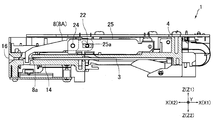
- FIG. 1 is a plan view for explaining the structure of a card reader 1 according to an embodiment of the present invention.
- FIG. 2 is a longitudinal sectional view for explaining the structure of the card reader 1 shown in FIG.
- FIG. 3 is a plan view of the card 2 shown in FIG.
- FIG. 4 is a schematic side view of the IC contact block 6 and the lock lever 8 shown in FIG.
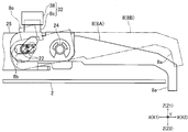
- FIG. 5 is a diagram showing the lock lever 8 and the shaft support member 25 shown in FIG. 2 from the opposite side.
- FIG. 6 is a block diagram of a configuration related to control when the card reader 1 shown in FIG. 1 is inserted.
- the card reader 1 of this embodiment is a manual card reader, and the card reader 1 manually inserts and pulls out a contact IC card 2 (hereinafter referred to as “card 2”).
- the card reader 1 is a so-called dip type card reader in which the user manually inserts the card 2 into the card reader 1 and pulls out the card 2 from the card reader 1 to read and record data. It is.
- the card reader 1 is mounted and used in a predetermined host device (not shown).
- the card reader 1 is formed with a card passage 3 through which the card 2 passes.
- the card reader 1 includes a frame 4 in which a card passage 3 is formed, an IC contact block 6 having a plurality of IC contact springs 5, and a magnetic head 7.
- the card reader 1 also includes a lock lever 8 as a lock member that prevents the card 2 inserted into the card reader 1 from being pulled out, and a lock lever drive mechanism 9 as a lock member drive mechanism that moves the lock lever 8. ing.
- the card 2 moves in the X direction shown in FIG. Specifically, the card 2 is inserted in the X1 direction, and the card 2 is pulled out in the X2 direction. That is, the X direction is the moving direction of the card 2, the X1 direction is the inserting direction of the card 2 into the card reader 1, and the X2 direction is the pulling direction of the card 2 from the card reader 1. Further, the Z direction in FIG. 1 and the like orthogonal to the X direction is the thickness direction of the card 2 moving on the card passage 3, and the Y direction in FIG. 1 orthogonal to the X direction and the Z direction is the card passage. This is the width direction of the card 2 moving along the path 3.
- the X direction is referred to as “front-rear direction”
- the Y direction is referred to as “left-right direction”
- the Z direction is referred to as “up-down direction”.
- the X1 direction side is the “back” side
- the X2 direction side is the “front” side
- the Z1 direction side is the “upper” side
- the Z2 direction side is the “lower” side.
- Card 2 is a substantially rectangular vinyl chloride card having a thickness of about 0.7 to 0.8 mm. This card 2 is a card compliant with international standards and JIS standards. On the back surface of the card 2, a magnetic stripe on which magnetic data is recorded is formed.
- the card 2 contains an IC chip, and an external connection terminal 2a of the IC chip is formed on the front surface of the card 2 as shown in FIG.
- the external connection terminal 2 a is formed at a predetermined position with the longitudinal end 1 b of the card 2 as a reference.
- the card 2 is inserted into the card reader 1 from the one end 2b side in a state where the front surface of the card 2 faces upward and the longitudinal direction of the card 2 substantially coincides with the front-rear direction.
- a part of the front end side of the card reader 1 is a cutout portion 13 cut out so that the user can insert the card 2 and pull out the card 2.
- the cutout portion 13 having a substantially U shape when viewed from the top and bottom is formed so as to be cut out from the front end of the frame 4 toward the back side.
- a notch 13 is formed at an intermediate position of the frame 4, and protrusions 14, 15 are formed on both sides of the notch 13 in the left-right direction.
- the card passage 3 is formed so that the shape when viewed from the left-right direction is a straight line.
- the front end of the card passage 3 is an insertion slot 16 into which the card 2 is inserted. That is, the insertion port 16 is formed at the front end of the protrusions 14 and 15.
- the magnetic head 7 is disposed at the front end portion of the protrusion 14. Further, the magnetic head 7 is disposed so that the gap of the magnetic head 7 faces the card passage 3 from the lower side.
- the IC contact block 6 is disposed on the back end side portion of the card reader 1.
- the IC contact block 6 is arranged so that the IC contact spring 5 faces the card passage 3 from the upper side, and the IC contact block 6 is arranged on the upper side of the card passage 3.
- a card contact portion 6 a with which the tip of the card 2 (the end in the insertion direction of the card 2, that is, the back end) abuts is formed at the back end of the IC contact block 6.
- the IC contact block 6 is connected to the upper end portion of the frame 4 via two arms 18 constituting a parallel link mechanism, and moves up and down while sliding in the front-rear direction. Specifically, the IC contact block 6 descends when it moves to the back side and rises when it moves to the near side. Further, the IC contact block 6 is biased toward the front side by a tension coil spring 19. Note that a part of the IC contact block 6 may be engaged with the guide groove formed in the frame 4, and the IC contact block 6 may move up and down while sliding in the front-rear direction while being guided by the guide groove.
- the IC contact block 6 descends while sliding to the back side, and a plurality of IC contact springs 5 come into contact with the external connection terminals 2 a of the card 2. Further, when the card 2 inserted into the card reader 1 is pulled out to the front side, the IC contact block 6 is moved forward by the biasing force of the tension coil spring 19 so that the IC contact spring 5 is separated from the front surface of the card 2. Ascend while sliding to the side.
- the lock lever 8 is a pull-out prevention position (that is, a position where the card passage 3 is closed, which prevents the card 2 inserted to the back side until the contact position where the external connection terminal 2a contacts the IC contact spring 5).
- 8A and a position indicated by a solid line in FIG. 5 and a drawable position where the card 2 can be inserted and extracted (that is, a position where the card passage 3 is opened, a position indicated by a two-dot chain line in FIG. 5). It is possible to move between 8B.
- the lock lever 8 of this embodiment is rotatable between the pull-out prevention position 8A and the pull-out possible position 8B.
- the lock lever drive mechanism 9 rotates the lock lever 8 between the pull-out prevention position 8A and the pull-out possible position 8B.
- the lock lever drive mechanism 9 includes a solenoid 21 and a fixing pin 22 fixed to the plunger of the solenoid 21.
- the fixing pin 22 is arranged so that the axial direction thereof matches the left-right direction.
- the lock lever 8 is rotatably held by a rotation center shaft 24 arranged with the left-right direction as an axial direction.
- the lock lever 8 has the left-right direction as an axis direction of rotation and is centered on the rotation center shaft 24. It can be turned.
- the rotation center shaft 24 is fixed to a shaft support member 25 fixed to the frame 4.
- the shaft support member 25 is formed with guide grooves 25a through which the left and right end portions of the fixing pin 22 are inserted.
- the guide groove 25a is formed in a long hole shape whose longitudinal direction is the front-rear direction.
- the lock lever 8 is formed with a pull-out preventing portion 8a with which the rear end of the card 2 (the pull-out side end of the card 2, that is, the front end) can contact when the lock lever 8 is in the pull-out prevention position 8A. Yes.
- the pull-out preventing portion 8a is formed in a planar shape orthogonal to the front-rear direction when the lock lever 8 is in the pull-out preventing position 8A.
- the lock lever 8 is formed with a cam groove 8b into which the one end portion of the fixing pin 22 in the left-right direction is inserted.
- the solenoid 21 is fixed to the frame 4 so that the plunger of the solenoid 21 protrudes toward the front side.
- the left and right end portions of the fixing pin 22 are inserted into the guide grooves 25a formed in the shaft support member 25, and the plunger moves in the front-rear direction.
- one end portion of the fixing pin 22 in the left-right direction is inserted into a cam groove 8b formed in the lock lever 8, and when the plunger moves in the front-rear direction, the pull-out prevention is performed around the rotation center shaft 24.
- the lock lever 8 rotates between the position 8A and the pullable position 8B.
- the card reader 1 also includes an insertion start detection mechanism 30 that detects that the card 2 has been inserted into the insertion slot 16 and the card 2 to a contact position where the external connection terminal 2a of the card 2 can contact the IC contact spring 5.
- a card insertion detection mechanism 31 that detects insertion and a lock lever detection mechanism 32 as a lock member detection mechanism that detects that the lock lever 8 is in the pull-out prevention position 8A are provided (see FIG. 6). 1 and 2, the insertion start detection mechanism 30, the card insertion detection mechanism 31, and the lock lever detection mechanism 32 are not shown.
- the insertion start detection mechanism 30, the card insertion detection mechanism 31, and the lock lever detection mechanism 32 are connected to a control unit 33 that controls the card reader 1.
- a lock lever drive mechanism 9 is also connected to the control unit 33.
- the solenoid 21 constituting the lock lever drive mechanism 9 is connected to the control unit 33.
- the control unit 33 is connected to a host control unit 34 that is a control unit of a host device on which the card reader 1 is mounted.
- the insertion start detection mechanism 30 is, for example, a transmissive optical sensor having a light emitting element and a light receiving element, and is arranged on the front end side portion of the protruding portion 14. For example, the light emitting element and the light receiving element of the insertion start detection mechanism 30 are opposed to each other with the card passage 3 interposed therebetween in the vertical direction.
- the insertion start detection mechanism 30 includes, for example, a transmissive optical sensor having a light emitting element and a light receiving element, and a lever member having a light shielding portion that blocks between the light emitting element and the light receiving element of the sensor. May be.
- the lever member is arranged at a position where the card 2 inserted into the insertion slot 16 comes into contact, and when the card 2 comes into contact with the lever member, the light-shielding portion of the lever member moves between the light emitting element and the light receiving element of the sensor. Intercept.
- the insertion start detection mechanism 30 may be comprised by the contact member and the lever member which can contact a contact switch, when the card
- the card insertion detection mechanism 31 includes, for example, a transmissive optical sensor 36 having a light emitting element and a light receiving element, and a light shielding portion 6 b formed on the IC contact block 6. Yes.
- the light emitting element and the light receiving element are arranged to face each other with a predetermined gap.
- the light shielding portion 6b is formed at a position that blocks between the light emitting element and the light receiving element of the sensor 36 when the card 2 is inserted to a contact position where the external connection terminal 2a of the card 2 can contact the IC contact spring 5.
- the card insertion detection mechanism 31 is connected to the control unit 33.
- the sensor 36 is connected to the control unit 33.
- the card insertion detection mechanism 31 may be constituted by, for example, a lever member provided separately from the IC contact block 6 and a transmission type optical sensor.
- the lever member is disposed at a position where the tip end side of the card 2 contacts, and when the card 2 is inserted to a contact position where the external connection terminal 2a can contact the IC contact spring 5, The light shielding portion of the lever member blocks between the light emitting element and the light receiving element.
- the card insertion detection mechanism 31 may be comprised, for example from the contact switch and the lever member which can contact a contact switch. In this case, when the card 2 is inserted to a contact position where the external connection terminal 2a can contact the IC contact spring 5, the lever member contacts the contact switch.
- the lever member may be formed on the IC contact block 6 or may be provided separately from the IC contact block 6.
- the lock lever detection mechanism 32 includes, for example, a transmissive optical sensor 38 having a light emitting element and a light receiving element, and a light shielding portion 8 c formed on the lock lever 8. .
- the light emitting element and the light receiving element are arranged to face each other with a predetermined gap.
- the light-shielding portion 8c is formed at a position that blocks between the light-emitting element and the light-receiving element of the sensor 38 when the lock lever 8 is in the pull-out prevention position 8A. By being blocked by the light shielding portion 8c, it is detected that the lock lever 8 is in the pull-out prevention position 8A.
- the lock lever detection mechanism 32 is connected to the control unit 33.
- the sensor 38 is connected to the control unit 33.
- the lock lever detection mechanism 32 may be comprised from the contact switch and the lever member which can contact a contact switch, for example. In this case, for example, when the lock lever 8 is at the pull-out prevention position 8A, the lever member comes into contact with the contact switch, and it is detected that the lock lever 8 is at the pull-out prevention position 8A. In this case, the lever member is formed on the lock lever 8.
- the sensor 36 has a detection area of a certain range, and when the light shielding portion 6b of the IC contact block 6 is in the detection area of the sensor 36, the card 2 reaches the contact position where the external connection terminal 2a contacts the IC contact spring 5. Is inserted by the card insertion detecting mechanism 31.
- the tip of the card 2 is inserted to the detection start position by the card insertion detection mechanism 31 (that is, the contact position where the external connection terminal 2a contacts the IC contact spring 5).
- the distance L1 in the front-rear direction with respect to the pull-out prevention portion 8a when is at the pull-out prevention position 8A is shorter than the length of the card 2 in the front-rear direction (that is, the length in the longitudinal direction of the card 2). That is, as shown in FIG. 4B, when the rear end of the card 2 comes into contact with the pull-out prevention portion 8a when the lock lever 8 is at the pull-out prevention position 8A, the detection start position by the card insertion detection mechanism 31 is detected. Also, the lock lever 8 is arranged so that the tip of the card 2 is inserted into the back side.
- FIG. 7 is a flowchart showing an example of a control flow when the card reader 1 shown in FIG. 1 is inserted.
- the IC contact block 6 In a standby state before the card 2 is inserted into the card reader 1, the IC contact block 6 is biased to the near side by the biasing force of the tension coil spring 19, and the IC contact spring 5 is not in contact with the card 2. Is rising. Further, in a standby state before the card 2 is inserted into the card reader 1, the lock lever 8 is in the pullable position 8B.
- step S1 when the control unit 33 receives a card insertion wait command transmitted from the host control unit 34 (step S1), the control unit 33 inserts the card 2 into the insertion slot 16 within a predetermined insertion start waiting time. It is determined whether or not this has been detected by the insertion start detection mechanism 30 (steps S2 and S3).
- the insertion start detection mechanism 30 detects that the card 2 has been inserted into the insertion slot 16 within the predetermined insertion start waiting time in steps S2 and S3
- the control unit 33 determines that the card 2 is in the insertion slot 16. It is determined that it has been inserted.
- the controller 33 determines whether or not the card insertion detection mechanism 31 has detected that the card 2 has been inserted up to a contact position where the external connection terminal 2a contacts the IC contact spring 5 within a predetermined insertion completion waiting time. (Steps S4 and S5).
- step S5 the controller 33 detects by the card insertion detection mechanism 31 that the card 2 has been inserted to a contact position where the external connection terminal 2a contacts the IC contact spring 5 within a predetermined insertion completion waiting time.
- the control part 33 starts the lock lever drive mechanism 9 (step S6).
- the control unit 33 supplies current to the solenoid 21 to drive the solenoid 21. That is, when it is detected by the card insertion detection mechanism 31 that the IC card 2 has been inserted to the contact position, the control unit 33 causes the lock lever drive mechanism 9 to pull the lock lever 8 at the pull-out position 8B. Move towards.
- control unit 33 determines whether or not the lock lever detection mechanism 32 has detected that the lock lever 8 is in the pull-out prevention position 8A within a predetermined insertion completion waiting time (steps S7 and S8). In steps S7 and S8, the control unit 33 continues to move the lock lever drive mechanism 9 for a predetermined time until the lock lever detection mechanism 32 detects that the lock lever 8 is in the pull-out prevention position 8A.
- Step S9 the controller 33 detects that the card 2 has been inserted up to the contact position by the card insertion detection mechanism 31 and detects by the lock lever detection mechanism 32 that the lock lever 8 is in the pull-out prevention position 8A. Then, it detects that the insertion of the card 2 has been completed, and transmits an insertion completion detection signal to the host controller 34. Thereafter, the control unit 33 receives an activation command transmitted from the host control unit 34 to activate the card 2 and activates the card 2 based on the activation command, so that the card reader 1 and the card 2 are activated. Data communication with the.
- the control unit 33 inserts the insertion slot 16 into the insertion slot 16. It is determined that the card 2 is not inserted. Thereafter, the control unit 33 transmits an insertion start non-detection signal indicating that the insertion of the card 2 into the card reader 1 has not been started to the upper control unit 34 (step S10), returns to step S1, and returns to the upper control unit.
- the card insertion waiting command transmitted from 34 is received.
- control unit 33 performs predetermined insertion without detecting by the card insertion detection mechanism 31 that the card 2 has been inserted to the contact position where the external connection terminal 2a contacts the IC contact spring 5 in steps S4 and S5. If it is determined that the card 2 has not been inserted up to the contact position after the completion waiting time has elapsed, or if it is determined in steps S7 and S8 that the lock lever 8 is not in the pull-out prevention position 8A, the insertion is completed in the host controller 34. An undetected signal is transmitted (step S11), and then the process returns to step S1 to receive a card insertion wait command transmitted from the host controller 34.
- the controller 33 detects that the card 2 has been inserted up to the contact position within a predetermined time after the insertion start detection mechanism 30 detects that the card 2 has been inserted into the insertion slot 16.
- an insertion completion non-detection signal is transmitted to the host control unit 34.
- the lock lever 8 is returned to the pullable position 8B.
- the host control unit 34 that has received the insertion completion non-detection signal executes a predetermined error process before transmitting a card insertion wait command to the control unit 33.
- Step S1 of this embodiment is a card insertion wait command receiving step for receiving a card insertion wait command from the host control unit 34.
- Steps S2 and S3 are predetermined after receiving the card insertion wait command from the host control unit 34.
- This is an insertion start determination step of determining whether or not the insertion start detection mechanism 30 has detected that the card 2 has been inserted into the insertion slot 16 within the first time.
- steps S4 and S5 of this embodiment when it is determined that the card 2 has been inserted into the insertion slot 16 in the insertion start determination step, the card 2 has been inserted up to the contact position within the predetermined second time. Is a card insertion determination step for determining whether the card 2 is detected by the card insertion detection mechanism 31.
- Steps S7 and S8 are predetermined when the card insertion determination step determines that the card 2 has been inserted up to the contact position. This is a lock member position determination step for determining whether or not the lock lever detection mechanism 32 has detected that the lock lever 8 is in the pull-out prevention position 8A within the third time.
- the controller 33 detects that the card 2 has been inserted up to the contact position by the card insertion detection mechanism 31 and locks that the lock lever 8 is at the pull-out prevention position 8A. When detected by the lever detection mechanism 32, it detects that the insertion of the card 2 has been completed, and transmits an insertion completion detection signal to the host controller 34. Further, in this embodiment, the control unit 33 then receives an activation command transmitted from the host control unit 34 to activate the card 2 and activates the card 2 based on the activation command. Data communication is performed between the card reader 1 and the card 2.
- data communication is performed between the card reader 1 and the card 2 in a state where the lock lever 8 prevents the card 2 from being pulled out. Therefore, in this embodiment, when the card insertion detection mechanism 31 starts to detect that the card 2 has been inserted to the contact position where the external connection terminal 2a contacts the IC contact spring 5, the lock lever 8 Data communication between the card reader 1 and the card 2 is possible even when the distance L1 in the front-rear direction with respect to the pull-out prevention unit 8a at the pull-out prevention position 8A is shorter than the length of the card 2 in the front-rear direction. It becomes possible to prevent the card 2 from being forcibly pulled out during the course.
- the control unit 33 moves the lock lever drive mechanism 9 for a predetermined time until the lock lever detection mechanism 32 detects that the lock lever 8 is in the pull-out prevention position 8A. to continue. Therefore, in this embodiment, the card 2 is inserted up to the contact position, but at least for a predetermined time even when the card 2 is not inserted up to a position where the lock lever 8 can move to the pull-out prevention position 8A. Meanwhile, the card reader 1 does not enter an error state. Therefore, in this embodiment, it is possible to give the user a grace period for inserting the card 2 to a position where the lock lever 8 can move to the pull-out prevention position 8A.
- the user can insert the card 2 to a position where the lock lever 8 can move to the pull-out prevention position 8A within the grace period.
- the detection mechanism 32 can detect that the lock lever 8 is in the pull-out prevention position 8A, and can detect that the card 2 has been inserted.
- the lock lever 8 is rotatable between the pull-out prevention position 8A and the pull-out possible position 8B.
- the lock lever 8 formed in a pin shape is disposed so that the axial direction of the lock lever 8 coincides with the vertical direction, and between the pull-out prevention position 8A and the pull-out possible position 8B. It may be movable up and down.
- the card contact portion 6a is formed in the IC contact block 6, and the IC contact block 6 is pushed to the back side by the card 2 that contacts the card contact portion 6a, and the IC contact spring 5 is moved. It moves until it contacts the external connection terminal 2a of the card 2.
- a moving mechanism for moving the IC contact block 6 until the IC contact spring 5 comes into contact with the external connection terminal 2a may be provided.
- the card contact portion 6 a is not formed on the IC contact block 6.
- the moving mechanism moves the IC contact block 6 until it contacts 2a.
- the moving mechanism includes a drive source such as a solenoid.
- the card reader 1 includes the magnetic head 7, but the card reader 1 may not include the magnetic head 7.
- the card 2 is a vinyl chloride card having a thickness of about 0.7 to 0.8 mm.
- the card 2 is a PET (thickness of about 0.18 to 0.36 mm).
Landscapes
- Engineering & Computer Science (AREA)
- Physics & Mathematics (AREA)
- General Physics & Mathematics (AREA)
- Theoretical Computer Science (AREA)
- Artificial Intelligence (AREA)
- Computer Vision & Pattern Recognition (AREA)
- Coupling Device And Connection With Printed Circuit (AREA)
- Details Of Connecting Devices For Male And Female Coupling (AREA)
- Conveying Record Carriers (AREA)
Abstract
カードリーダとICカードとの間でデータの通信を行っているときのICカードの強制的な引抜きを防止し、かつ、ロック部材がICカードをロックしているときの通信エラーの発生を防止することが可能な手動式のカードリーダを提供する。このカードリーダでは、制御部33は、ICカードの外部接続端子がIC接点バネと接触可能な接触位置までICカードが挿入されたことがカード挿入検知機構31によって検知され、かつ、ロック部材がカードの引抜きを防止する引抜き防止位置にあることがロック部材検知機構32によって検知されると、ICカードの挿入が完了したことを検知する。
Description
本発明は、接触式のICカードの挿入と引抜きとが手動で行われる手動式のカードリーダに関する。
従来、接触式のICカードの挿入と引抜きとが手動で行われる手動式のICカードリーダが知られている(たとえば、特許文献1参照)。従来の手動式のICカードリーダは、たとえば、図8に示すように、ICカード102(以下、「カード102」とする)に形成されるICチップの外部接続端子102aに接触する複数のIC接点バネ103と、IC接点バネ103を保持するIC接点ブロック104と、IC接点ブロック104を移動可能に保持するアーム105と、ICカードリーダの手前側へIC接点ブロック104を付勢する引張りコイルバネ(図示省略)とを備えている。
IC接点ブロック104には、カード挿入口から挿入されたカード102の先端102bが当接するカード当接部104aが形成されている。このICカードリーダでは、カード挿入口から挿入されたカード102の先端102bがカード当接部104aに当接した後、さらにカード102が挿入されると、IC接点ブロック104がICカードリーダの奥側へ移動しながらカード102に近づいて、IC接点バネ103が外部接続端子102aに所定の接触圧で接触する。
また、このICカードリーダは、外部接続端子102aがIC接点バネ103に接触する位置までカード102が挿入されたことを検知するカード挿入検知機構106と、外部接続端子102aがIC接点バネ103に接触する位置まで挿入されたカード102の引抜きを防止するロックレバー107とを備えている。ロックレバー107には、外部接続端子102aがIC接点バネ103に接触する位置まで挿入されたカード102の後端102cが接触可能な平面状の引抜き防止部107aが形成されている。
カード挿入検知機構106は、たとえば、発光素子と受光素子とが対向配置された光学式のセンサ108と、IC接点ブロック104に形成される遮光部104bとから構成されており、外部接続端子102aがIC接点バネ103に接触する位置までカード102が挿入されると、センサ108の発光素子から受光素子に向かう光が遮光部104bに遮られる。また、センサ108の発光素子から受光素子に向かう光が遮光部104bに遮られることで、外部接続端子102aがIC接点バネ103に接触する位置までカード102が挿入されたことが検知される。
このICカードリーダでは、外部接続端子102aがIC接点バネ103に接触する位置までカード102が挿入されたことがカード挿入検知機構106によって検知されると、ロックレバー107によってカード102がロックされる。また、外部接続端子102aがIC接点バネ103に接触する位置までカード102が挿入されたことがカード挿入検知機構106によって検知されると、ICカードリーダとカード102との間でデータの通信を行うために、カード102が活性化される。
一般に、センサ108には、一定範囲の検知領域がある。そのため、IC接点ブロック104の遮光部104bがセンサ108の検知領域内にある場合に、外部接続端子102aがIC接点バネ103に接触する位置までカード102が挿入されたことがカード挿入検知機構106によって検知される。ここで、カード挿入検知機構106によってカード102が挿入されたことが検知されたときに、挿入されたカード102をロックレバー107によって確実にロックするためには、図8(A)に示すように、カード挿入検知機構106による検知開始位置までカード102の先端102bが挿入されたとき(すなわち、外部接続端子102aがIC接点バネ103に接触する位置までカード102が挿入されたことがカード挿入検知機構106によって検知され始めるとき(より具体的には、センサ108の検知領域に遮光部104bが入り始めるとき))のカード102の先端102bと、ロックレバー107がカード102をロックしているときのロックレバー107の引抜き防止部107aとの距離L101がカード102の長さよりも長くなっている必要がある。
しかしながら、このようになっていると、ロックレバー107によってカード102がロックされた状態でICカードリーダとカード102との間でデータの通信を行っているときに、何らかの原因によって、たとえば、図8(B)に示すように、カード102の後端102cが引抜き防止部107aに接触する位置まで移動するおそれがある。なお、距離L101とカード2の長さとを等しくすることが理想であるが、センサ108の公差や設置誤差等の影響で、距離L101とカード102の長さとを厳密に等しく管理することは困難である。
また、ロックレバー107によってカード102がロックされた状態でICカードリーダとカード102との間でデータの通信を行っているときに、たとえば、カード102の後端102cが引抜き防止部107aに接触する位置まで移動すると、図8(B)に示すように、センサ108の検知領域から遮光部104bが外れて、外部接続端子102aがIC接点バネ103に接触する位置までカード102が挿入されたことが検知されなくなるおそれがある。また、外部接続端子102aがIC接点バネ103から離れるおそれもある。そのため、距離L101がカード102の長さよりも長くなっていると、ICカードリーダとカード102との間のデータ通信が不安定になり、通信エラーが発生するおそれがある。
そこで、本発明の課題は、カードリーダとICカードとの間でデータの通信を行っているときのICカードの強制的な引抜きを防止し、かつ、ロック部材がICカードをロックしているときの通信エラーの発生を防止することが可能な手動式のカードリーダを提供することにある。また、本発明の課題は、かかるカードリーダの制御方法を提供することにある。
上記の課題を解決するため、本発明のカードリーダは、接触式のICカードの挿入と引抜きとが手動で行われる手動式のカードリーダにおいて、ICカードが通過するカード通過路と、ICカードに形成されるICチップの外部接続端子に接触する複数のIC接点バネを有するIC接点ブロックと、外部接続端子がIC接点バネと接触可能な接触位置までICカードが挿入されたことを検知するカード挿入検知機構と、接触位置まで挿入されたICカードの引抜きを防止する引抜き防止位置とICカードの挿入および引抜きが可能となる引抜き可能位置との間で移動するロック部材と、引抜き防止位置と引抜き可能位置との間でロック部材を移動させるロック部材駆動機構と、ロック部材が引抜き防止位置にあることを検知するロック部材検知機構と、カードリーダを制御する制御部とを備え、ICカードの挿入方向側端を先端とし、ICカードの引抜き方向側端を後端とすると、ロック部材には、ロック部材が引抜き防止位置にあるときに、ICカードの後端が接触可能な引抜き防止部が形成され、接触位置までICカードが挿入されたことがカード挿入検知機構によって検知され始めるときのICカードの先端と、ロック部材が引抜き防止位置にあるときの引抜き防止部との、ICカードの移動方向における距離は、ICカードの移動方向におけるICカードの長さよりも短くなっており、制御部は、接触位置までICカードが挿入されたことがカード挿入検知機構によって検知され、かつ、ロック部材が引抜き防止位置にあることがロック部材検知機構によって検知されると、ICカードの挿入が完了したことを検知することを特徴とする。
本発明において、たとえば、制御部は、ICカードの挿入が完了したことを検知すると、カードリーダが搭載される上位装置の制御部である上位制御部に挿入完了検知信号を送信し、その後、ICカードを活性化させるために上位制御部から送信される活性化指令に基づいてICカードを活性化させる。
本発明のカードリーダでは、接触位置までICカードが挿入されたことがカード挿入検知機構によって検知され始めるときのICカードの先端と、ロック部材が引抜き防止位置にあるときの引抜き防止部との、ICカードの移動方向における距離は、ICカードの移動方向におけるICカードの長さよりも短くなっている。また、本発明では、制御部は、接触位置までICカードが挿入されたことがカード挿入検知機構によって検知され、かつ、ロック部材が引抜き防止位置にあることがロック部材検知機構によって検知されると、ICカードの挿入が完了したことを検知する。そのため、本発明では、たとえば、制御部が、ICカードの挿入が完了したことを検知したときに上位制御部に挿入完了検知信号を送信し、その後、上位制御部から送信される活性化指令に基づいてICカードを活性化させてカードリーダとICカードとの間でデータの通信を行うことで、ロック部材によってICカードの引抜きが防止されている状態で、カードリーダとICカードとの間でデータの通信を行うことが可能になる。したがって、本発明では、カードリーダとICカードとの間でデータの通信を行っているときのICカードの強制的な引抜きを防止し、かつ、ロック部材がICカードをロックしているときの通信エラーの発生を防止することが可能になる。
本発明において、カードリーダは、たとえば、ICカードの挿入口にICカードが挿入されたことを検知する挿入開始検知機構を備えている。この場合には、たとえば、制御部は、挿入口にICカードが挿入されたことが挿入開始検知機構によって検知された後の所定時間内に、接触位置までICカードが挿入されたことがカード挿入検知機構によって検知されない場合、または、ロック部材が引抜き防止位置にあることがロック部材検知機構によって検知されない場合に、挿入完了未検知信号を上位制御部に送信する。
本発明において、制御部は、接触位置までICカードが挿入されたことがカード挿入検知機構によって検知されると、引抜き可能位置にあるロック部材をロック部材駆動機構によって引抜き防止位置に向かって移動させるとともに、接触位置までICカードが挿入されたことがカード挿入検知機構によって検知された後、ロック部材が引抜き防止位置にあることがロック部材検知機構によって検知されるまで、所定時間の間、ロック部材駆動機構を動かし続けることが好ましい。このように構成すると、接触位置まではICカードが挿入されたが、ロック部材が引抜き防止位置に移動可能となる位置までICカードが挿入されていない場合であっても、少なくとも所定時間の間、カードリーダはエラー状態にならない。したがって、ロック部材が引抜き防止位置に移動可能となる位置までICカードを挿入するための猶予をユーザに与えることが可能になる。また、ユーザは、猶予時間内に、ロック部材が引抜き防止位置に移動可能となる位置までICカードを挿入することが可能になり、その結果、制御部は、ロック部材検知機構によってロック部材が引抜き防止位置にあることを検知して、ICカードの挿入が完了したことを検知することが可能になる。
本発明のカードリーダは、たとえば、カードリーダが搭載される上位装置の制御部である上位制御部からカード挿入待ち指令を受信するカード挿入待ち指令受信ステップと、上位制御部からカード挿入待ち指令を受信した後、所定の第1時間内に、挿入口にICカードが挿入されたことが挿入開始検知機構によって検知されたのか否かを判断する挿入開始判断ステップと、挿入開始判断ステップで挿入口にICカードが挿入されたと判断されると、所定の第2時間内に、接触位置までICカードが挿入されたことがカード挿入検知機構によって検知されたのか否かを判断するカード挿入判断ステップと、カード挿入判断ステップで接触位置までICカードが挿入されたと判断されると、所定の第3時間内に、ロック部材が引抜き防止位置にあることがロック部材検知機構によって検知されたのか否かを判断するロック部材位置判断ステップとを備える制御方法によって制御される。このカードリーダの制御方法では、たとえば、挿入開始判断ステップで挿入口にICカードが挿入されていないと判断されると、上位制御部に挿入開始未検知信号を送信した後にカード挿入待ち指令受信ステップへ戻り、カード挿入判断ステップで接触位置までICカードが挿入されていないと判断されると、または、ロック部材位置判断ステップでロック部材が引抜き防止位置にないと判断されると、上位制御部に挿入完了未検知信号を送信した後にカード挿入待ち指令受信ステップへ戻る。
以上のように、本発明では、カードリーダとICカードとの間でデータの通信を行っているときのICカードの強制的な引抜きを防止し、かつ、ロック部材がICカードをロックしているときの通信エラーの発生を防止することが可能になる。
以下、図面を参照しながら、本発明の実施の形態を説明する。
(カードリーダの構成)
図1は、本発明の実施の形態にかかるカードリーダ1の構造を説明するための平面図である。図2は、図1に示すカードリーダ1の構造を説明するための縦断面図である。図3は、図1に示すカード2の平面図である。図4は、図1に示すIC接点ブロック6およびロックレバー8等の概略側面図である。図5は、図2に示すロックレバー8および軸支持部材25等を反対側から示す図である。図6は、図1に示すカードリーダ1のカード挿入時の制御に関連する構成のブロック図である。
図1は、本発明の実施の形態にかかるカードリーダ1の構造を説明するための平面図である。図2は、図1に示すカードリーダ1の構造を説明するための縦断面図である。図3は、図1に示すカード2の平面図である。図4は、図1に示すIC接点ブロック6およびロックレバー8等の概略側面図である。図5は、図2に示すロックレバー8および軸支持部材25等を反対側から示す図である。図6は、図1に示すカードリーダ1のカード挿入時の制御に関連する構成のブロック図である。
本形態のカードリーダ1は、手動式のカードリーダであり、カードリーダ1では、接触式のICカード2(以下、「カード2」とする)の挿入と引抜きとが手動で行われる。具体的には、カードリーダ1は、ユーザがカードリーダ1へのカード2の挿入とカードリーダ1からのカード2の引抜きとを手動で行ってデータの読取りや記録を行ういわゆるディップ式のカードリーダである。このカードリーダ1は、所定の上位装置(図示省略)に搭載されて使用される。
図2に示すように、カードリーダ1には、カード2が通過するカード通過路3が形成されている。カードリーダ1は、内部にカード通過路3が形成されるフレーム4と、複数のIC接点バネ5を有するIC接点ブロック6と、磁気ヘッド7とを備えている。また、カードリーダ1は、カードリーダ1に挿入されたカード2の引抜きを防止するロック部材としてのロックレバー8と、ロックレバー8を移動させるロック部材駆動機構としてのロックレバー駆動機構9とを備えている。
本形態では、図1等に示すX方向にカード2が移動する。具体的には、X1方向にカード2が挿入され、X2方向にカード2が引き抜かれる。すなわち、X方向は、カード2の移動方向であり、X1方向は、カードリーダ1へのカード2の挿入方向であり、X2方向は、カードリーダ1からのカード2の引抜き方向である。また、X方向に直交する図1等のZ方向は、カード通過路3を移動するカード2の厚さ方向であり、X方向とZ方向とに直交する図1等のY方向は、カード通過路3を移動するカード2の幅方向である。以下の説明では、X方向を「前後方向」、Y方向を「左右方向」、Z方向を「上下方向」とする。また、X1方向側を「奥」側、X2方向側を「手前」側、Z1方向側を「上」側、Z2方向側を「下」側とする。
カード2は、厚さが0.7~0.8mm程度の略長方形状の塩化ビニール製のカードである。このカード2は、国際規格やJIS規格に準拠したカードである。カード2の裏面には、磁気データが記録される磁気ストライプが形成されている。また、カード2には、ICチップが内蔵されており、図3に示すように、カード2のおもて面には、ICチップの外部接続端子2aが形成されている。外部接続端子2aは、カード2の長手方向の一端2bを基準とする所定の位置に形成されている。カード2は、カード2のおもて面が上側を向くとともにカード2の長手方向が前後方向と略一致した状態で、かつ、一端2b側からカードリーダ1に挿入される。
図1に示すように、カードリーダ1の手前端側の一部分は、ユーザによるカード2の挿入およびカード2の引抜きが可能となるように切り欠かれた切欠部13となっている。具体的には、上下方向から見たときの形状が略U形状となる切欠部13が、フレーム4の手前端から奥側に向かって切り欠かれるように形成されている。また、左右方向では、フレーム4の中間位置に切欠部13が形成されており、左右方向における切欠部13の両側には、突出部14、15が形成されている。
カード通過路3は、図2に示すように、左右方向から見たときの形状が直線状となるように形成されている。カード通過路3の手前端は、カード2が挿入される挿入口16となっている。すなわち、突出部14、15の手前端に挿入口16が形成されている。磁気ヘッド7は、突出部14の手前端部分に配置されている。また、磁気ヘッド7は、磁気ヘッド7のギャップが下側からカード通過路3に臨むように配置されている。
IC接点ブロック6は、カードリーダ1の奥端側部分に配置されている。また、IC接点ブロック6は、IC接点バネ5が上側からカード通過路3に臨むように配置されており、IC接点ブロック6は、カード通過路3の上側に配置されている。図4に示すように、IC接点ブロック6の奥端には、カード2の先端(カード2の挿入方向側端、すなわち、奥端)が当接するカード当接部6aが形成されている。
また、IC接点ブロック6は、平行リンク機構を構成する2個のアーム18を介してフレーム4の上端側部分に連結されており、前後方向にスライドしながら上下動する。具体的には、IC接点ブロック6は、奥側に移動すると下降し、手前側に移動すると上昇する。また、IC接点ブロック6は、引張りコイルバネ19によって手前側に付勢されている。なお、フレーム4に形成されるガイド溝にIC接点ブロック6の一部が係合するとともに、このガイド溝に案内されて、IC接点ブロック6が前後方向にスライドしながら上下動しても良い。
本形態では、カードリーダ1の奥側へ挿入されたカード2の先端がIC接点ブロック6のカード当接部6aに係合した後、さらに奥側へカード2が挿入されると、IC接点ブロック6は、奥側にスライドしながら下降して、カード2の外部接続端子2aに複数のIC接点バネ5が接触する。また、カードリーダ1に挿入されたカード2が手前側に引き抜かれると、カード2のおもて面からIC接点バネ5が離れるように、引張りコイルバネ19の付勢力によって、IC接点ブロック6が手前側にスライドしながら上昇する。
ロックレバー8は、外部接続端子2aがIC接点バネ5に接触する接触位置まで奥側へ挿入されたカード2の引抜きを防止する引抜き防止位置(すなわち、カード通過路3を閉鎖する位置、図2に示す位置および図5の実線で示す位置)8Aと、カード2の挿入および引抜きが可能となる引抜き可能位置(すなわち、カード通過路3を開放する位置、図5の二点鎖線で示す位置)8Bとの間で移動可能となっている。本形態のロックレバー8は、引抜き防止位置8Aと引抜き可能位置8Bとの間で回動可能となっている。
ロックレバー駆動機構9は、引抜き防止位置8Aと引抜き可能位置8Bとの間でロックレバー8を回動させる。このロックレバー駆動機構9は、ソレノイド21と、ソレノイド21のプランジャに固定される固定ピン22とを備えている。固定ピン22は、その軸方向と左右方向とが一致するように配置されている。
ロックレバー8は、左右方向を軸方向として配置される回動中心軸24に回動可能に保持されており、左右方向を回動の軸方向として、かつ、回動中心軸24を中心にして回動可能となっている。回動中心軸24は、フレーム4に固定される軸支持部材25に固定されている。軸支持部材25には、固定ピン22の左右の両端側部分が挿通されるガイド溝25aが形成されている。ガイド溝25aは、前後方向を長手方向とする長孔状に形成されている。ロックレバー8には、ロックレバー8が引抜き防止位置8Aにあるときに、カード2の後端(カード2の引抜き方向側端、すなわち、手前端)が接触可能な引抜き防止部8aが形成されている。引き抜き防止部8aは、ロックレバー8が引抜き防止位置8Aにあるときに、前後方向に直交する平面状に形成されている。また、ロックレバー8には、固定ピン22の左右方向の一端側部分が挿通されるカム溝8bが形成されている。
ソレノイド21は、ソレノイド21のプランジャが手前側へ突出するようにフレーム4に固定されている。上述のように、固定ピン22の左右の両端側部分は、軸支持部材25に形成されるガイド溝25aに挿通されており、プランジャは前後方向へ移動する。また、固定ピン22の左右方向の一端側部分は、ロックレバー8に形成されるカム溝8bに挿通されており、プランジャが前後方向へ移動すると、回動中心軸24を中心にして、引抜き防止位置8Aと引抜き可能位置8Bとの間でロックレバー8が回動する。本形態では、引抜き可能位置8Bから引抜き防止位置8Aに向かってロックレバー8が回動するときには、引抜き防止部8aが下側に向かって移動し、引抜き防止位置8Aから引抜き可能位置8Bに向かってロックレバー8が回動するときには、引抜き防止部8aが上側に向かって移動する。
また、カードリーダ1は、挿入口16にカード2が挿入されたことを検知する挿入開始検知機構30と、カード2の外部接続端子2aがIC接点バネ5に接触可能な接触位置までカード2が挿入されたことを検知するカード挿入検知機構31と、ロックレバー8が引抜き防止位置8Aにあることを検知するロック部材検知機構としてのロックレバー検知機構32とを備えている(図6参照)。なお、図1、図2では、挿入開始検知機構30、カード挿入検知機構31およびロックレバー検知機構32の図示を省略している。
挿入開始検知機構30、カード挿入検知機構31およびロックレバー検知機構32は、カードリーダ1を制御する制御部33に接続されている。制御部33には、ロックレバー駆動機構9も接続されている。具体的には、ロックレバー駆動機構9を構成するソレノイド21が制御部33に接続されている。また、制御部33は、カードリーダ1が搭載される上位装置の制御部である上位制御部34に接続されている。
挿入開始検知機構30は、たとえば、発光素子と受光素子とを有する透過型の光学式のセンサであり、突出部14の手前端側部分に配置されている。挿入開始検知機構30の発光素子と受光素子とは、たとえば、上下方向においてカード通過路3を挟んだ状態で対向配置されている。なお、挿入開始検知機構30は、たとえば、発光素子と受光素子とを有する透過型の光学式のセンサと、このセンサの発光素子と受光素子との間を遮る遮光部を有するレバー部材とによって構成されても良い。この場合には、レバー部材は、挿入口16に挿入されたカード2が接触する位置に配置され、カード2がレバー部材に接触すると、レバー部材の遮光部がセンサの発光素子と受光素子との間を遮る。また、挿入開始検知機構30は、たとえば、接点スイッチと、カード2が接触すると接点スイッチに接触可能なレバー部材とによって構成されても良い。
カード挿入検知機構31は、図4に示すように、たとえば、発光素子と受光素子とを有する透過型の光学式のセンサ36と、IC接点ブロック6に形成される遮光部6bとから構成されている。センサ36では、発光素子と受光素子とが所定の隙間を介して対向配置されている。遮光部6bは、カード2の外部接続端子2aがIC接点バネ5に接触可能な接触位置までカード2が挿入されたときに、センサ36の発光素子と受光素子との間を遮る位置に形成されており、センサ36の発光素子から受光素子に向かう光が遮光部6bに遮られることで、外部接続端子2aがIC接点バネ5に接触可能な接触位置までカード2が挿入されたことが検知される。上述のように、カード挿入検知機構31は、制御部33に接続されている。具体的には、センサ36が制御部33に接続されている。
なお、カード挿入検知機構31は、たとえば、IC接点ブロック6とは別に設けられたレバー部材と、透過型の光学式のセンサとから構成されても良い。この場合には、レバー部材は、カード2の先端側が接触する位置に配置されており、外部接続端子2aがIC接点バネ5に接触可能な接触位置までカード2が挿入されたときに、センサの発光素子と受光素子との間をレバー部材の遮光部が遮る。また、カード挿入検知機構31は、たとえば、接点スイッチと、接点スイッチに接触可能なレバー部材とから構成されても良い。この場合には、外部接続端子2aがIC接点バネ5に接触可能な接触位置までカード2が挿入されると、レバー部材が接点スイッチに接触する。この場合には、レバー部材は、IC接点ブロック6に形成されても良いし、IC接点ブロック6とは別に設けられても良い。
ロックレバー検知機構32は、図5に示すように、たとえば、発光素子と受光素子とを有する透過型の光学式のセンサ38と、ロックレバー8に形成される遮光部8cとから構成されている。センサ38では、発光素子と受光素子とが所定の隙間を介して対向配置されている。遮光部8cは、ロックレバー8が引抜き防止位置8Aにあるときに、センサ38の発光素子と受光素子との間を遮る位置に形成されており、センサ38の発光素子から受光素子に向かう光が遮光部8cに遮られることで、ロックレバー8が引抜き防止位置8Aにあることが検知される。上述のように、ロックレバー検知機構32は、制御部33に接続されている。具体的には、センサ38が制御部33に接続されている。
なお、ロックレバー検知機構32は、たとえば、接点スイッチと、接点スイッチに接触可能なレバー部材とから構成されても良い。この場合には、たとえば、ロックレバー8が引抜き防止位置8Aにあるときに、レバー部材が接点スイッチに接触して、ロックレバー8が引抜き防止位置8Aにあることが検知される。また、この場合には、レバー部材は、ロックレバー8に形成される。
センサ36には、一定範囲の検知領域があり、IC接点ブロック6の遮光部6bがセンサ36の検知領域内にある場合に、外部接続端子2aがIC接点バネ5に接触する接触位置までカード2が挿入されたことがカード挿入検知機構31によって検知される。本形態では、図4(A)に示すように、カード挿入検知機構31による検知開始位置までカード2の先端が挿入されたとき(すなわち、外部接続端子2aがIC接点バネ5に接触する接触位置までカード2が挿入されたことがカード挿入検知機構31によって検知され始めるとき(具体的には、センサ36の検知領域に遮光部6bが入り始めるとき))のカード2の先端と、ロックレバー8が引抜き防止位置8Aにあるときの引抜き防止部8aとの前後方向における距離L1は、前後方向におけるカード2の長さ(すなわち、カード2の長手方向の長さ)よりも短くなっている。すなわち、図4(B)に示すように、ロックレバー8が引抜き防止位置8Aにあるときの引抜き防止部8aにカード2の後端が接触するときに、カード挿入検知機構31による検知開始位置よりも奥側へカード2の先端が挿入されるように、ロックレバー8が配置されている。
(カードリーダの制御方法)
図7は、図1に示すカードリーダ1のカード挿入時の制御フローの一例を示すフローチャートである。
図7は、図1に示すカードリーダ1のカード挿入時の制御フローの一例を示すフローチャートである。
カードリーダ1にカード2が挿入される前の待機状態においては、IC接点ブロック6は、引張りコイルバネ19の付勢力によって手前側に付勢されており、IC接点バネ5がカード2に接触しない位置まで上昇している。また、カードリーダ1にカード2が挿入される前の待機状態においては、ロックレバー8は、引抜き可能位置8Bにある。
この状態において、上位制御部34から送信されるカード挿入待ち指令を制御部33が受信すると(ステップS1)、制御部33は、所定の挿入開始待ち時間内に、挿入口16にカード2が挿入されたことが挿入開始検知機構30によって検知されたのか否かを判断する(ステップS2、S3)。制御部33は、ステップS2、S3において、所定の挿入開始待ち時間内に、挿入口16にカード2が挿入されたことが挿入開始検知機構30によって検知された場合、挿入口16にカード2が挿入されたと判断する。その後、制御部33は、所定の挿入完了待ち時間内に、外部接続端子2aがIC接点バネ5に接触する接触位置までカード2が挿入されたことがカード挿入検知機構31によって検知されたのか否かを判断する(ステップS4、S5)。
制御部33は、ステップS4、S5において、所定の挿入完了待ち時間内に、外部接続端子2aがIC接点バネ5に接触する接触位置までカード2が挿入されたことがカード挿入検知機構31によって検知された場合、接触位置までカード2が挿入されたと判断する。その後、制御部33は、ロックレバー駆動機構9を起動する(ステップS6)。具体的には、制御部33は、ソレノイド21に電流を供給してソレノイド21を駆動する。すなわち、制御部33は、接触位置までICカード2が挿入されたことがカード挿入検知機構31によって検知されると、引抜き可能位置8Bにあるロックレバー8をロックレバー駆動機構9によって引抜き防止位置8Aに向かって移動させる。
その後、制御部33は、所定の挿入完了待ち時間内に、ロックレバー8が引抜き防止位置8Aにあることがロックレバー検知機構32によって検知されたのか否かを判断する(ステップS7、S8)。ステップS7、S8において、制御部33は、ロックレバー8が引抜き防止位置8Aにあることがロックレバー検知機構32によって検知されるまで、所定時間の間、ロックレバー駆動機構9を動かし続ける。
制御部33は、ステップS7、S8において、ロックレバー8が引抜き防止位置8Aにあると判断すると、その後、カードリーダ1へのカード2の挿入が完了したとの挿入完了検知信号を上位制御部34に送信する(ステップS9)。すなわち、制御部33は、接触位置までカード2が挿入されたことがカード挿入検知機構31によって検知され、かつ、ロックレバー8が引抜き防止位置8Aにあることがロックレバー検知機構32によって検知されると、カード2の挿入が完了したことを検知して、挿入完了検知信号を上位制御部34に送信する。その後、制御部33は、カード2を活性化させるために上位制御部34から送信される活性化指令を受信し、活性化指令に基づいてカード2を活性化させて、カードリーダ1とカード2との間でデータの通信を行う。
一方、制御部33は、ステップS2、S3において、挿入口16にカード2が挿入されたことが挿入開始検知機構30によって検知されずに、所定の挿入開始待ち時間を経過した場合、挿入口16にカード2が挿入されていないと判断する。その後、制御部33は、カードリーダ1へのカード2の挿入が開始されていないとの挿入開始未検知信号を上位制御部34に送信し(ステップS10)、ステップS1へ戻って、上位制御部34から送信されるカード挿入待ち指令を受信する。
また、制御部33は、ステップS4、S5において、外部接続端子2aがIC接点バネ5に接触する接触位置までカード2が挿入されたことがカード挿入検知機構31によって検知されずに、所定の挿入完了待ち時間を経過して接触位置までカード2が挿入されていないと判断すると、または、ステップS7、S8において、ロックレバー8が引抜き防止位置8Aにないと判断すると、上位制御部34に挿入完了未検知信号を送信し(ステップS11)、その後、ステップS1へ戻って、上位制御部34から送信されるカード挿入待ち指令を受信する。すなわち、制御部33は、挿入口16にカード2が挿入されたことが挿入開始検知機構30によって検知された後の所定時間内に、接触位置までカード2が挿入されたことがカード挿入検知機構31によって検知されない場合、または、ロックレバー8が引抜き防止位置8Aにあることがロックレバー検知機構32によって検知されない場合に、挿入完了未検知信号を上位制御部34に送信する。なお、ステップS11では、ロックレバー8を引抜き可能位置8Bまで戻す。また、挿入完了未検知信号を受信した上位制御部34は、カード挿入待ち指令を制御部33に送信する前に所定のエラー処理を実行する。
本形態のステップS1は、上位制御部34からカード挿入待ち指令を受信するカード挿入待ち指令受信ステップであり、ステップS2、S3は、上位制御部34からカード挿入待ち指令を受信した後、所定の第1時間内に、挿入口16にカード2が挿入されたことが挿入開始検知機構30によって検知されたのか否かを判断する挿入開始判断ステップである。また、本形態のステップS4、S5は、挿入開始判断ステップで挿入口16にカード2が挿入されたと判断されるときに、所定の第2時間内に、接触位置までカード2が挿入されたことがカード挿入検知機構31によって検知されたのか否かを判断するカード挿入判断ステップであり、ステップS7、S8は、カード挿入判断ステップで接触位置までカード2が挿入されたと判断されるときに、所定の第3時間内に、ロックレバー8が引抜き防止位置8Aにあることがロックレバー検知機構32によって検知されたのか否かを判断するロック部材位置判断ステップである。
(本形態の主な効果)
以上説明したように、本形態では、制御部33は、接触位置までカード2が挿入されたことがカード挿入検知機構31によって検知され、かつ、ロックレバー8が引抜き防止位置8Aにあることがロックレバー検知機構32によって検知されると、カード2の挿入が完了したことを検知して、挿入完了検知信号を上位制御部34に送信する。また、本形態では、制御部33は、その後、カード2を活性化させるために上位制御部34から送信される活性化指令を受信し、活性化指令に基づいてカード2を活性化させて、カードリーダ1とカード2との間でデータの通信を行っている。すなわち、本形態では、ロックレバー8によってカード2の引抜きが防止されている状態で、カードリーダ1とカード2との間でデータの通信が行われている。そのため、本形態では、外部接続端子2aがIC接点バネ5に接触する接触位置までカード2が挿入されたことがカード挿入検知機構31によって検知され始めるときのカード2の先端と、ロックレバー8が引抜き防止位置8Aにあるときの引抜き防止部8aとの前後方向における距離L1が、前後方向におけるカード2の長さよりも短くなっていても、カードリーダ1とカード2との間でデータの通信を行っているときのカード2の強制的な引抜きを防止することが可能になる。
以上説明したように、本形態では、制御部33は、接触位置までカード2が挿入されたことがカード挿入検知機構31によって検知され、かつ、ロックレバー8が引抜き防止位置8Aにあることがロックレバー検知機構32によって検知されると、カード2の挿入が完了したことを検知して、挿入完了検知信号を上位制御部34に送信する。また、本形態では、制御部33は、その後、カード2を活性化させるために上位制御部34から送信される活性化指令を受信し、活性化指令に基づいてカード2を活性化させて、カードリーダ1とカード2との間でデータの通信を行っている。すなわち、本形態では、ロックレバー8によってカード2の引抜きが防止されている状態で、カードリーダ1とカード2との間でデータの通信が行われている。そのため、本形態では、外部接続端子2aがIC接点バネ5に接触する接触位置までカード2が挿入されたことがカード挿入検知機構31によって検知され始めるときのカード2の先端と、ロックレバー8が引抜き防止位置8Aにあるときの引抜き防止部8aとの前後方向における距離L1が、前後方向におけるカード2の長さよりも短くなっていても、カードリーダ1とカード2との間でデータの通信を行っているときのカード2の強制的な引抜きを防止することが可能になる。
本形態では、ステップS7、S8において、制御部33は、ロックレバー8が引抜き防止位置8Aにあることがロックレバー検知機構32によって検知されるまで、所定時間の間、ロックレバー駆動機構9を動かし続ける。そのため、本形態では、接触位置まではカード2が挿入されたが、ロックレバー8が引抜き防止位置8Aに移動可能となる位置までカード2が挿入されていない場合であっても、少なくとも所定時間の間、カードリーダ1はエラー状態にならない。したがって、本形態では、ロックレバー8が引抜き防止位置8Aに移動可能となる位置までカード2を挿入するための猶予をユーザに与えることが可能になる。また、本形態では、ユーザは、猶予時間内に、ロックレバー8が引抜き防止位置8Aに移動可能となる位置までカード2を挿入することが可能になり、その結果、制御部33は、ロックレバー検知機構32によってロックレバー8が引抜き防止位置8Aにあることを検知して、カード2の挿入が完了したことを検知することが可能になる。
(他の実施の形態)
上述した形態は、本発明の好適な形態の一例ではあるが、これに限定されるものではなく本発明の要旨を変更しない範囲において種々変形実施が可能である。
上述した形態は、本発明の好適な形態の一例ではあるが、これに限定されるものではなく本発明の要旨を変更しない範囲において種々変形実施が可能である。
上述した形態では、ロックレバー8は、引抜き防止位置8Aと引抜き可能位置8Bとの間で回動可能となっている。この他にもたとえば、ピン状に形成されるロックレバー8が、ロックレバー8の軸方向と上下方向とが一致するように配置されるとともに、引抜き防止位置8Aと引抜き可能位置8Bとの間で上下動可能となっていても良い。
上述した形態では、IC接点ブロック6にカード当接部6aが形成されており、IC接点ブロック6は、カード当接部6aに当接するカード2によって奥側に押されて、IC接点バネ5がカード2の外部接続端子2aに接触するまで移動する。この他にもたとえば、IC接点バネ5が外部接続端子2aに接触するまでIC接点ブロック6を移動させる移動機構が設けられていても良い。この場合には、IC接点ブロック6にカード当接部6aが形成されていない。また、この場合には、外部接続端子2aがIC接点バネ5に接触可能な接触位置までカード2が挿入されたことがカード挿入検知機構31に検知されると、IC接点バネ5が外部接続端子2aに接触するまで移動機構がIC接点ブロック6を移動させる。なお、この場合の移動機構は、ソレノイド等の駆動源を備えている。
上述した形態では、カードリーダ1は、磁気ヘッド7を備えているが、カードリーダ1は、磁気ヘッド7を備えていなくても良い。また、上述した形態では、カード2は、厚さが0.7~0.8mm程度の塩化ビニール製のカードであるが、カード2は、厚さが0.18~0.36mm程度のPET(ポリエチレンテレフタレート)カードであっても良いし、所定の厚さの紙カード等であっても良い。
1 カードリーダ
2 カード(ICカード)
2a 外部接続端子
3 カード通過路
5 IC接点バネ
6 IC接点ブロック
8 ロックレバー(ロック部材)
8a 引抜き防止部
8A 引抜き防止位置
8B 引抜き可能位置
9 ロックレバー駆動機構(ロック部材駆動機構)
16 挿入口
30 挿入開始検知機構
31 カード挿入検知機構
32 ロックレバー検知機構(ロック部材検知機構)
33 制御部
34 上位制御部
S1 カード挿入待ち指令受信ステップ
S2、S3 挿入開始判断ステップ
S4、S5 カード挿入判断ステップ
S7、S8 ロック部材位置判断ステップ
X ICカードの移動方向
X1 ICカードの挿入方向
X2 ICカードの引抜き方向
2 カード(ICカード)
2a 外部接続端子
3 カード通過路
5 IC接点バネ
6 IC接点ブロック
8 ロックレバー(ロック部材)
8a 引抜き防止部
8A 引抜き防止位置
8B 引抜き可能位置
9 ロックレバー駆動機構(ロック部材駆動機構)
16 挿入口
30 挿入開始検知機構
31 カード挿入検知機構
32 ロックレバー検知機構(ロック部材検知機構)
33 制御部
34 上位制御部
S1 カード挿入待ち指令受信ステップ
S2、S3 挿入開始判断ステップ
S4、S5 カード挿入判断ステップ
S7、S8 ロック部材位置判断ステップ
X ICカードの移動方向
X1 ICカードの挿入方向
X2 ICカードの引抜き方向
Claims (6)
- 接触式のICカードの挿入と引抜きとが手動で行われる手動式のカードリーダにおいて、
前記ICカードが通過するカード通過路と、前記ICカードに形成されるICチップの外部接続端子に接触する複数のIC接点バネを有するIC接点ブロックと、前記外部接続端子が前記IC接点バネと接触可能な接触位置まで前記ICカードが挿入されたことを検知するカード挿入検知機構と、前記接触位置まで挿入された前記ICカードの引抜きを防止する引抜き防止位置と前記ICカードの挿入および引抜きが可能となる引抜き可能位置との間で移動するロック部材と、前記引抜き防止位置と前記引抜き可能位置との間で前記ロック部材を移動させるロック部材駆動機構と、前記ロック部材が前記引抜き防止位置にあることを検知するロック部材検知機構と、前記カードリーダを制御する制御部とを備え、
前記ICカードの挿入方向側端を先端とし、前記ICカードの引抜き方向側端を後端とすると、
前記ロック部材には、前記ロック部材が前記引抜き防止位置にあるときに、前記ICカードの後端が接触可能な引抜き防止部が形成され、
前記接触位置まで前記ICカードが挿入されたことが前記カード挿入検知機構によって検知され始めるときの前記ICカードの先端と、前記ロック部材が前記引抜き防止位置にあるときの前記引抜き防止部との、前記ICカードの移動方向における距離は、前記ICカードの移動方向における前記ICカードの長さよりも短くなっており、
前記制御部は、前記接触位置まで前記ICカードが挿入されたことが前記カード挿入検知機構によって検知され、かつ、前記ロック部材が前記引抜き防止位置にあることが前記ロック部材検知機構によって検知されると、前記ICカードの挿入が完了したことを検知することを特徴とするカードリーダ。 - 前記制御部は、前記ICカードの挿入が完了したことを検知すると、前記カードリーダが搭載される上位装置の制御部である上位制御部に挿入完了検知信号を送信し、その後、前記ICカードを活性化させるために前記上位制御部から送信される活性化指令に基づいて前記ICカードを活性化させることを特徴とする請求項1記載のカードリーダ。
- 前記ICカードの挿入口に前記ICカードが挿入されたことを検知する挿入開始検知機構を備えることを特徴とする請求項1または2記載のカードリーダ。
- 前記制御部は、前記挿入口に前記ICカードが挿入されたことが前記挿入開始検知機構によって検知された後の所定時間内に、前記接触位置まで前記ICカードが挿入されたことが前記カード挿入検知機構によって検知されない場合、または、前記ロック部材が前記引抜き防止位置にあることが前記ロック部材検知機構によって検知されない場合に、挿入完了未検知信号を前記上位制御部に送信することを特徴とする請求項3記載のカードリーダ。
- 前記制御部は、前記接触位置まで前記ICカードが挿入されたことが前記カード挿入検知機構によって検知されると、前記引抜き可能位置にある前記ロック部材を前記ロック部材駆動機構によって前記引抜き防止位置に向かって移動させるとともに、前記接触位置まで前記ICカードが挿入されたことが前記カード挿入検知機構によって検知された後、前記ロック部材が前記引抜き防止位置にあることが前記ロック部材検知機構によって検知されるまで、所定時間の間、前記ロック部材駆動機構を動かし続けることを特徴とする請求項1から4のいずれかに記載のカードリーダ。
- 請求項3に記載のカードリーダの制御方法であって、
前記カードリーダが搭載される上位装置の制御部である上位制御部からカード挿入待ち指令を受信するカード挿入待ち指令受信ステップと、
前記上位制御部から前記カード挿入待ち指令を受信した後、所定の第1時間内に、前記挿入口に前記ICカードが挿入されたことが前記挿入開始検知機構によって検知されたのか否かを判断する挿入開始判断ステップと、
前記挿入開始判断ステップで前記挿入口に前記ICカードが挿入されたと判断されると、所定の第2時間内に、前記接触位置まで前記ICカードが挿入されたことが前記カード挿入検知機構によって検知されたのか否かを判断するカード挿入判断ステップと、
前記カード挿入判断ステップで前記接触位置まで前記ICカードが挿入されたと判断されると、所定の第3時間内に、前記ロック部材が前記引抜き防止位置にあることが前記ロック部材検知機構によって検知されたのか否かを判断するロック部材位置判断ステップとを備え、
前記挿入開始判断ステップで前記挿入口に前記ICカードが挿入されていないと判断されると、前記上位制御部に挿入開始未検知信号を送信した後に前記カード挿入待ち指令受信ステップへ戻り、
前記カード挿入判断ステップで前記接触位置まで前記ICカードが挿入されていないと判断されると、または、前記ロック部材位置判断ステップで前記ロック部材が前記引抜き防止位置にないと判断されると、前記上位制御部に挿入完了未検知信号を送信した後に前記カード挿入待ち指令受信ステップへ戻ることを特徴とするカードリーダの制御方法。
Priority Applications (1)
| Application Number | Priority Date | Filing Date | Title |
|---|---|---|---|
| US15/563,080 US10528771B2 (en) | 2015-03-31 | 2016-03-29 | Card reader and method for controlling card reader |
Applications Claiming Priority (2)
| Application Number | Priority Date | Filing Date | Title |
|---|---|---|---|
| JP2015-071347 | 2015-03-31 | ||
| JP2015071347A JP6374340B2 (ja) | 2015-03-31 | 2015-03-31 | カードリーダおよびカードリーダの制御方法 |
Publications (1)
| Publication Number | Publication Date |
|---|---|
| WO2016158948A1 true WO2016158948A1 (ja) | 2016-10-06 |
Family
ID=57005752
Family Applications (1)
| Application Number | Title | Priority Date | Filing Date |
|---|---|---|---|
| PCT/JP2016/060124 Ceased WO2016158948A1 (ja) | 2015-03-31 | 2016-03-29 | カードリーダおよびカードリーダの制御方法 |
Country Status (3)
| Country | Link |
|---|---|
| US (1) | US10528771B2 (ja) |
| JP (1) | JP6374340B2 (ja) |
| WO (1) | WO2016158948A1 (ja) |
Families Citing this family (2)
| Publication number | Priority date | Publication date | Assignee | Title |
|---|---|---|---|---|
| JP7154038B2 (ja) | 2018-05-18 | 2022-10-17 | 日本電産サンキョー株式会社 | カードリーダ |
| JP7819588B2 (ja) * | 2022-07-06 | 2026-02-25 | サクサ株式会社 | カードリーダのシャッタ構造 |
Citations (3)
| Publication number | Priority date | Publication date | Assignee | Title |
|---|---|---|---|---|
| JP2004318229A (ja) * | 2003-04-11 | 2004-11-11 | Matsushita Electric Ind Co Ltd | Icカ−ドリ−ダ |
| JP2008203918A (ja) * | 2007-02-16 | 2008-09-04 | Nidec Sankyo Corp | 媒体処理装置及びその制御方法 |
| JP2010026826A (ja) * | 2008-07-22 | 2010-02-04 | Nidec Sankyo Corp | カードリーダ |
Family Cites Families (9)
| Publication number | Priority date | Publication date | Assignee | Title |
|---|---|---|---|---|
| JP3507684B2 (ja) * | 1998-01-19 | 2004-03-15 | 株式会社三協精機製作所 | カード処理方法 |
| JP3367447B2 (ja) * | 1999-03-08 | 2003-01-14 | 松下電器産業株式会社 | Icカードリーダ |
| DE60127468T2 (de) * | 2000-01-24 | 2008-01-31 | Nidec Sankyo Corp. | Manueller Chipkartenleser |
| DE60219354T2 (de) * | 2001-11-22 | 2008-03-13 | Nidec Sankyo Corp. | Ic-kartenleser |
| US7175085B2 (en) * | 2003-12-17 | 2007-02-13 | Nidec Sankyo Corporation | Card reader |
| US7364076B2 (en) * | 2004-10-25 | 2008-04-29 | Nidec Sankyo Corporation | Card reader |
| JP4993350B2 (ja) * | 2007-02-02 | 2012-08-08 | 株式会社ユニバーサルエンターテインメント | カード処理装置 |
| US8931698B2 (en) * | 2010-02-08 | 2015-01-13 | Nidec Sankyo Corporation | Card reader |
| US20150136850A1 (en) * | 2013-03-29 | 2015-05-21 | Nidec Sankyo Corporation | Card medium processing device |
-
2015
- 2015-03-31 JP JP2015071347A patent/JP6374340B2/ja not_active Expired - Fee Related
-
2016
- 2016-03-29 US US15/563,080 patent/US10528771B2/en active Active
- 2016-03-29 WO PCT/JP2016/060124 patent/WO2016158948A1/ja not_active Ceased
Patent Citations (3)
| Publication number | Priority date | Publication date | Assignee | Title |
|---|---|---|---|---|
| JP2004318229A (ja) * | 2003-04-11 | 2004-11-11 | Matsushita Electric Ind Co Ltd | Icカ−ドリ−ダ |
| JP2008203918A (ja) * | 2007-02-16 | 2008-09-04 | Nidec Sankyo Corp | 媒体処理装置及びその制御方法 |
| JP2010026826A (ja) * | 2008-07-22 | 2010-02-04 | Nidec Sankyo Corp | カードリーダ |
Also Published As
| Publication number | Publication date |
|---|---|
| JP2016192053A (ja) | 2016-11-10 |
| US10528771B2 (en) | 2020-01-07 |
| US20190332825A1 (en) | 2019-10-31 |
| JP6374340B2 (ja) | 2018-08-15 |
Similar Documents
| Publication | Publication Date | Title |
|---|---|---|
| US10410022B2 (en) | Card reader and card reader control method | |
| CN101617326B (zh) | 介质处理装置及其控制方法 | |
| JP2019200682A (ja) | カードリーダ | |
| US8657202B2 (en) | Card reader | |
| CN107085735B (zh) | 读卡器 | |
| JP6374340B2 (ja) | カードリーダおよびカードリーダの制御方法 | |
| CN102956062B (zh) | 卡处理装置 | |
| CN100407225C (zh) | 卡处理装置 | |
| US20060211288A1 (en) | Card reader and writer | |
| JP6151661B2 (ja) | カードリーダ | |
| JP6081884B2 (ja) | カードリーダ | |
| JP6449604B2 (ja) | カードリーダ | |
| JPWO2017057189A1 (ja) | カードリーダ | |
| US20080244629A1 (en) | Medium identification device | |
| WO2000016334A1 (en) | Cartridge | |
| JP2018055557A (ja) | カードリーダおよびカードリーダの制御方法 | |
| WO2014020646A1 (ja) | カード処理装置 | |
| JP6459713B2 (ja) | 磁気カードリーダ及びユーザ認証システム | |
| JP2008257285A (ja) | 記録メディア識別装置 | |
| JP2013134649A (ja) | カードリーダ | |
| JP2000128366A (ja) | カード供給装置 | |
| JP2008257282A (ja) | メディア識別装置 | |
| JP2008257284A (ja) | 記録メディア識別装置 | |
| JP2008257281A (ja) | 記録メディア識別装置 |
Legal Events
| Date | Code | Title | Description |
|---|---|---|---|
| 121 | Ep: the epo has been informed by wipo that ep was designated in this application |
Ref document number: 16772829 Country of ref document: EP Kind code of ref document: A1 |
|
| NENP | Non-entry into the national phase |
Ref country code: DE |
|
| 122 | Ep: pct application non-entry in european phase |
Ref document number: 16772829 Country of ref document: EP Kind code of ref document: A1 |