WO2016158533A1 - 支持装置、タービン、回転機械の組立方法、及び回転機械の分解方法 - Google Patents
支持装置、タービン、回転機械の組立方法、及び回転機械の分解方法 Download PDFInfo
- Publication number
- WO2016158533A1 WO2016158533A1 PCT/JP2016/058862 JP2016058862W WO2016158533A1 WO 2016158533 A1 WO2016158533 A1 WO 2016158533A1 JP 2016058862 W JP2016058862 W JP 2016058862W WO 2016158533 A1 WO2016158533 A1 WO 2016158533A1
- Authority
- WO
- WIPO (PCT)
- Prior art keywords
- main body
- lower half
- disposed
- recess
- horizontal
- Prior art date
- Legal status (The legal status is an assumption and is not a legal conclusion. Google has not performed a legal analysis and makes no representation as to the accuracy of the status listed.)
- Ceased
Links
Images






Classifications
-
- F—MECHANICAL ENGINEERING; LIGHTING; HEATING; WEAPONS; BLASTING
- F01—MACHINES OR ENGINES IN GENERAL; ENGINE PLANTS IN GENERAL; STEAM ENGINES
- F01D—NON-POSITIVE DISPLACEMENT MACHINES OR ENGINES, e.g. STEAM TURBINES
- F01D25/00—Component parts, details, or accessories, not provided for in, or of interest apart from, other groups
- F01D25/28—Supporting or mounting arrangements, e.g. for turbine casing
-
- F—MECHANICAL ENGINEERING; LIGHTING; HEATING; WEAPONS; BLASTING
- F01—MACHINES OR ENGINES IN GENERAL; ENGINE PLANTS IN GENERAL; STEAM ENGINES
- F01D—NON-POSITIVE DISPLACEMENT MACHINES OR ENGINES, e.g. STEAM TURBINES
- F01D9/00—Stators
- F01D9/02—Nozzles; Nozzle boxes; Stator blades; Guide conduits, e.g. individual nozzles
- F01D9/04—Nozzles; Nozzle boxes; Stator blades; Guide conduits, e.g. individual nozzles forming ring or sector
-
- F—MECHANICAL ENGINEERING; LIGHTING; HEATING; WEAPONS; BLASTING
- F05—INDEXING SCHEMES RELATING TO ENGINES OR PUMPS IN VARIOUS SUBCLASSES OF CLASSES F01-F04
- F05D—INDEXING SCHEME FOR ASPECTS RELATING TO NON-POSITIVE-DISPLACEMENT MACHINES OR ENGINES, GAS-TURBINES OR JET-PROPULSION PLANTS
- F05D2230/00—Manufacture
- F05D2230/60—Assembly methods
-
- F—MECHANICAL ENGINEERING; LIGHTING; HEATING; WEAPONS; BLASTING
- F05—INDEXING SCHEMES RELATING TO ENGINES OR PUMPS IN VARIOUS SUBCLASSES OF CLASSES F01-F04
- F05D—INDEXING SCHEME FOR ASPECTS RELATING TO NON-POSITIVE-DISPLACEMENT MACHINES OR ENGINES, GAS-TURBINES OR JET-PROPULSION PLANTS
- F05D2230/00—Manufacture
- F05D2230/70—Disassembly methods
Definitions
- the present invention relates to a support device, a turbine, a rotating machine assembling method, and a rotating machine disassembling method.
- the turbine blade ring is supported by a support device provided in the lower half of the passenger compartment.
- a support device provided in the lower half of the passenger compartment.
- the support device disclosed in Patent Document 1 includes a support attached to the lower half of the blade ring, a lower half liner that supports the support, and an upper half liner that presses the support.
- the thickness of the lower half liner By adjusting the thickness of the lower half liner, the position of the blade ring in the vertical direction is adjusted.
- the wing ring is prevented from lifting when the passenger compartment is released.
- An object of an aspect of the present invention is to provide a support device, a turbine, a method for assembling a rotating machine, and a method for disassembling a rotating machine that can smoothly adjust the position of an inner member such as a blade ring.
- a first aspect of the present invention is a rotating machine that supports an inner member on the outer member of a stationary body that is arranged around a rotating body that rotates about a rotating shaft and that has an outer member and an inner member that can be divided vertically.
- a main body portion disposed in a recess provided in an upper surface of a lower half portion of the outer member, and a front surface of the inner member provided on the main body portion and opposed to the lower half portion of the inner member.
- a support member that protrudes toward the lower half and has a protrusion that is detachably disposed in a hole provided in the lower half of the inner member; a bottom surface provided in the recess; and a main body.
- a first adjustment member disposed between a lower surface facing the bottom surface, a horizontal portion disposed above the main body portion, and an upper surface provided on the main body portion and opposed to each other via a first gap;
- an upper liner having a vertical portion disposed between the main body portion and a rear surface facing the inner wall surface, the upper liner being fixed to a lower half portion of the outer member.
- the upper liner is removed from the recess.
- the support member can be removed from the lower half of the inner member without lifting the rotor and inner member. Since the distance between the inner wall surface of the recess and the outer surface of the lower half of the inner member is larger than the outer dimension of the support member in the direction perpendicular and horizontal to the rotation axis, the support member can be supported without lifting the rotor and the inner member. Can be moved in the horizontal direction, and the protruding portion can be pulled out from the hole and removed from the lower half of the inner member.
- the first adjusting member can be accessed by removing the support member. Since the first adjustment member can be accessed without lifting the rotor and the inner member, the position adjustment of the inner member can be performed smoothly.
- the support member is moved out of the recess. Not only the removal operation but also the operation of attaching the support member can be carried out smoothly.
- the horizontal portion of the upper liner is disposed above the main body of the support member, the inner member is prevented from being lifted when the outer member is released.
- the inner member May be lifted.
- the horizontal portion of the upper liner fixed to the lower half of the outer member is disposed above the main body, the support member is prevented from being lifted, and the inner member is also prevented from being lifted. Further, the horizontal portion prevents the inner member from being lifted during operation of the rotating machine.
- the inner member is a stationary body, when the rotating body rotates, a force is applied to the inner member due to the flow of fluid, and the inner member also tries to move in the rotational direction.
- the horizontal portion is provided, the movement of the inner member can be suppressed via the support member.
- the vertical portion of the upper liner is disposed on the rear surface side of the main body portion of the support member, thereby preventing the protruding portion of the support member from coming out of the hole portion.
- the support member is connected to the lower half of the inner member by a bolt, even if the bolt is bent, the support member and the bolt are suppressed by the vertical portion, so the protruding portion is from the hole. It is prevented from falling off.
- the provision of the first gap prevents the horizontal portion and the main body from sticking to each other. Further, by integrating the horizontal portion and the vertical portion, the position of the inner member in the vertical direction can be adjusted with a small number of parts and a compact space.
- the first aspect of the present invention it is preferable to include a second adjustment member that adjusts the height of the horizontal portion.
- a second adjustment member that adjusts the height of the horizontal portion.
- the second adjustment member may be disposed between the bottom surface of the recess and a bottom surface provided on the vertical portion and facing the bottom surface.
- the height of the upper liner can be adjusted, and after installing the second adjustment member on the bottom surface, the upper liner may be installed on the second adjustment member, so that the assembly work can be performed smoothly. Can do.
- the first adjustment member and the second adjustment member may be formed of a single member.
- the number of parts can be reduced.
- the relative position of the height direction of a support member and an upper liner can be made constant.
- the upper liner is divided into a first part and a second part arranged below at least a part of the first part, and the second adjustment member is the first part. And the second portion.
- the position of the upper surface of a horizontal part can be adjusted.
- the second adjustment member can be used for adjustment without processing the upper surface of the horizontal part.
- the upper surface provided on the upper liner is disposed in the same plane as the upper surface of the lower half of the outer member or below the upper surface of the lower half of the outer member. It is preferable. Thereby, the lower surface of the upper half part of an outer member and the upper surface of the lower half part of an outer member can be stuck.
- the upper surface of the upper liner in the same plane as the upper surface of the lower half of the outer member, when the horizontal portion restrains the main body portion to prevent the inner member from lifting during operation of the rotating machine, Since the upper surface of the liner is supported by the upper half of the outer member, it is possible to suppress bending stress generated in the upper liner when the horizontal portion of the upper liner receives a force.
- a lower liner that is disposed between the main body portion and the first adjustment member and contacts the lower surface of the main body portion may be provided.
- the support member may move in the radial direction of the rotary shaft due to thermal deformation of the inner member.
- the first adjustment member is a thin plate or a film
- the first adjustment member is rubbed and deteriorated.
- the bottom surface of the recess below the first adjustment member may also deteriorate.
- the vertical portion is opposed to the rear surface of the main body portion via a second gap.
- the upper liner may be fixed to the lower half of the outer member by a bolt penetrating the upper liner.
- the upper liner may have a bolt hole that penetrates the vertical portion in the vertical direction and into which the bolt is inserted.
- a second aspect of the present invention provides a turbine including the support device according to the first aspect, the inner member, the outer member, and the rotating body.
- the position adjustment of the inner member can be carried out smoothly.
- the inner member is supported by the outer member of the stationary body that is disposed around the rotating body that rotates about the rotation axis and that can be divided into upper and lower parts and the inner member.
- a rotating machine assembling method for assembling a machine the step of disposing a first adjustment member on a bottom surface formed in a recess provided in an upper surface of a lower half portion of the outer member, and a main body portion and a main body portion
- a support member having a protrusion protruding from the front face toward the lower half of the inner member is inserted into the recess, and the protrusion is inserted into a hole provided in the lower half of the inner member.
- the distance between the inner wall surface provided in the recess and facing the radially inner side of the rotating shaft and the rear surface provided in the main body portion and facing the inner wall surface is perpendicular to the rotating shaft of the projecting portion in a horizontal direction.
- the main body so as to be larger than the dimensions
- the horizontal portion is disposed above the main body so as to face an upper surface provided in the main body via a first gap, and the vertical portion is disposed between the inner wall surface of the recess and the rear surface of the main body.
- fixing the upper liner to the lower half of the outer member.
- the assembly work of the support device can be performed in a state where the inner member is disposed inside the lower half of the outer member, and the position adjustment of the inner member is performed by the assembled support device.
- positioning the 1st adjustment member in the bottom face of a recessed part the height of a support member can be adjusted using a 1st adjustment member by arrange
- the distance between the inner wall surface of the recess and the rear surface of the main body is larger than the dimension in the direction perpendicular and horizontal to the rotation axis of the protrusion.
- the operation of inserting and the operation of taking out the protrusion from the hole can be performed.
- the upper liner is inserted into the concave portion, whereby the horizontal portion is disposed above the main body portion, and the vertical portion is disposed between the inner wall surface of the concave portion and the rear surface of the main body portion.
- the horizontal portion prevents the inner member from being lifted when the outer member is released and when the rotating machine is in operation.
- the protruding portion is prevented from dropping from the hole portion by the vertical portion.
- the step of disposing the main body portion on the first adjustment member includes disposing the projecting portion at an opening of the hole portion, and allowing the support member to be perpendicular to the rotation axis and It may include moving in a horizontal direction. Thereby, a protrusion part can be inserted in a hole part only by moving a supporting member to a horizontal direction.
- the third aspect of the present invention it is preferable to include a step of adjusting the height of the horizontal portion.
- the height of the upper surface of the horizontal portion relative to the upper surface of the lower half of the outer member and the positional relationship in the height direction between the support member and the upper liner can be adjusted.
- the step of adjusting the height of the horizontal portion is provided in the horizontal portion with respect to the upper surface of the lower half portion of the outer member after the upper liner is disposed in the recess. Adjusting the height of the upper surface.
- the upper surface of a horizontal part can be adjusted to appropriate height with respect to the upper surface of the lower half part of an outer member. For example, by processing the upper surface of the horizontal portion so that the upper surface of the horizontal portion is disposed in the same plane as the upper surface of the lower half of the outer member or below the upper surface of the lower half of the outer member, The upper surface of the lower half of the member and the lower surface of the upper half of the outer member can be brought into close contact with each other.
- a support device that supports the inner member on the outer member of a stationary body that is disposed around a rotating body that rotates about a rotating shaft and includes an outer member and an inner member that can be vertically divided.
- a rotating machine having a main body portion disposed in a recess provided in an upper surface of a lower half portion of the outer member; and a front surface provided in the main body portion.
- a support member that protrudes toward the lower half of the member and has a protrusion that is detachably disposed in a hole provided in the lower half of the inner member; a bottom surface provided in the recess; and the main body
- a first adjustment member arranged between a lower surface provided and opposed to the bottom surface to adjust the height of the support member; and a first gap formed on an upper surface provided on the main body portion and disposed above the main body portion.
- the first adjustment member is accessed by removing the upper liner, removing the support member from the lower half of the inner member without lifting the rotor and the inner member, and accessing the first adjustment member. Can be adjusted. Therefore, the position adjustment of the inner member using the support device can be performed smoothly.
- a support device a turbine, a rotating machine assembling method, and a rotating machine disassembling method that can smoothly adjust the position of the inner member.
- FIG. 1 is a sectional view showing the steam turbine concerning a 1st embodiment.
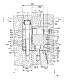
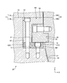
- FIG. 2 is a cross-sectional view showing the support device according to the first embodiment.
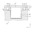
- FIG. 3 is a view taken along the line BB in FIG.
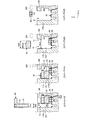
- FIG. 4 is a schematic diagram illustrating a steam turbine disassembling method according to the first embodiment.
- FIG. 5 is a schematic diagram showing a steam turbine assembling method according to the first embodiment.
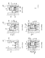
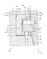
- FIG. 6 is a cross-sectional view showing a support device according to the second embodiment.
- FIG. 7 is a cross-sectional view illustrating a support device according to a third embodiment.
- FIG. 8 is a cross-sectional view showing a support device according to the fourth embodiment.
- FIG. 9 is a cross-sectional view illustrating a support device according to a fifth embodiment.
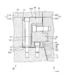
- FIG. 10 is a cross-sectional view illustrating a support device according to a sixth embodiment.
- FIG. 11 is a cross-sectional view illustrating a support device according to a seventh embodiment.
- FIG. 12 is a cross-sectional view illustrating a support device according to an eighth embodiment.
- FIG. 13 is a diagram illustrating a support device according to the ninth embodiment.
- FIG. 14 is a cross-sectional view illustrating a support device according to a ninth embodiment.
- FIG. 15 is a cross-sectional view showing a support device according to the tenth embodiment.
- an XYZ orthogonal coordinate system is set, and the positional relationship of each part will be described with reference to this XYZ orthogonal coordinate system.
- One direction in the horizontal plane is defined as the X-axis direction
- a direction orthogonal to the X-axis direction in the horizontal plane is defined as the Y-axis direction
- a vertical direction orthogonal to each of the X-axis direction and the Y-axis direction is defined as the Z-axis direction.
- the XY plane is parallel to the horizontal plane.
- the position in the Z-axis direction means the height.
- FIG. 1 is a cross-sectional view showing a steam turbine 1 which is a kind of rotating machine.
- the steam turbine 1 includes a rotating body 2 that rotates about a rotation axis AX, and a stationary body 3 that is disposed around the rotating body 2 and that can be divided vertically.
- the rotating body 2 has a rotor blade and a rotor that supports the rotor blade.
- the rotation axis AX is parallel to the Y axis.
- a direction perpendicular to the rotation axis AX is referred to as a radial direction
- a direction approaching the rotation axis AX is referred to as a radial inner side
- a direction away from the rotation axis AX is referred to as a radial outer side.
- the stationary body 3 includes a blade ring 10 that supports the stationary blade 4 and a casing 11 that is disposed around the blade ring 10.
- the casing 11 is supported by the gantry 100 and accommodates the rotor 2 and the blade ring 10.
- the blade ring 10 is an inner member disposed around the rotating body 2.
- the casing 11 is an outer member disposed outside the blade ring 10 with respect to the rotation axis AX.
- the blade ring 10 is divided into an upper half part 10A and a lower half part 10B, and the casing 11 is divided into an upper half part 11A and a lower half part 11B.
- the upper half 10A is the upper half of the inner member
- the lower half 10B is the lower half of the inner member.
- the upper half 11A is the upper half of the outer member, and the lower half 11B is the lower half of the outer member.
- the steam turbine 1 is provided in the passenger compartment 11 and includes a support device 5 that supports the blade ring 10.
- the support device 5 can support the blade ring 10 in the casing 11 and adjust the height of the blade ring 10. By adjusting the height of the blade ring 10 by the support device 5, the dimension of the gap between the rotor 2 and the blade ring 10 is adjusted.
- FIG. 2 is a cross-sectional view showing the support device 5 and shows a portion A of FIG.
- FIG. 3 is a view taken along the line BB in FIG. 2 and 3
- the support device 5 includes a support member 20 that supports the blade ring 10, an adjustment shim 40 that is a first adjustment member that adjusts the height of the support member 20, and a lower half portion 11B. And the lower liner 80 disposed between the support member 20 and the adjustment shim 40.
- the lower half portion 11B has an upper surface 16 joined to the lower surface of the upper half portion 11A and an inner surface 18 facing the outer surface 17 of the lower half portion 10B.
- a recess 12 is provided on the upper surface 16 of the lower half 11B.
- the recess 12 is formed so as to cut out a part of the upper surface 16 and a part of the inner surface 18.
- the concave portion 12 has a bottom surface 13 that faces the + Z direction and is parallel to the XY plane, an inner wall surface 14A that faces the + X direction that is radially inward of the rotation axis AX, and that is parallel to the YZ plane, and a -Y direction that faces the XZ plane. It has an inner wall surface 14B and an inner wall surface 14C that faces the + Y direction and is parallel to the XZ plane.
- a hole 15 extending in a horizontal direction is provided in the lower half 10B.
- the opening 15K of the hole 15 is formed on the outer surface 17 of the lower half 10B.
- the hole portion 15 has an inner wall surface 15A facing the ⁇ Z direction and parallel to the XY plane, and an inner wall surface 15B facing the + Z direction and parallel to the XY plane.
- the supporting member 20 is provided in the main body 21 disposed in the recess 12 and the main body 21 and protrudes from the front surface 21A of the main body 21 facing the lower half 10B toward the lower half 10B, and the lower half 10B. And a projecting portion 22 that is detachably disposed in a hole portion 15 provided in the base plate.
- the main body 21 has a front surface 21A facing the + Z direction that is radially inward of the rotation axis AX and parallel to the YZ plane, and a rear surface 21B facing the ⁇ X direction that is radially outward of the rotation axis AX and parallel to the YZ plane,
- the upper surface 21C faces the + Z direction and is parallel to the XY plane
- the lower surface 21D faces the ⁇ Z direction and is parallel to the XY plane.
- the front surface 21A of the main body 21 faces the outer surface 17 of the lower half 10B.
- the rear surface 21B of the main body portion 21 faces the front surface 62A of the vertical portion 62 of the upper liner 60 and can face the inner wall surface 14A of the recess 12.
- the upper surface 21 ⁇ / b> C of the main body portion 21 faces the lower surface 61 ⁇ / b> B of the horizontal portion 61 of the upper liner 60.
- the lower surface 21D of the main body 21 faces the upper surface 80A of the lower liner 80 and can face the bottom surface 13 provided in the recess 12.
- the protruding portion 22 protrudes in the + X direction from the front surface 21A.
- the protrusion 22 includes an upper surface 22A parallel to the XY plane and facing the inner wall surface 15A, a lower surface 22B parallel to the XY plane and facing the inner wall surface 15B, and a front surface 22C facing the + X direction and parallel to the YZ plane. Have.
- the lower surface 21D and the lower surface 22B are arranged in the same plane.
- the adjustment shim 40 is disposed between the bottom surface 13 provided in the recess 12 and the lower surface 21D provided in the main body portion 21 and facing the bottom surface 13, and adjusts the height of the support member 20.
- the adjustment shim 40 is a thin plate-like or film-like member.
- the adjustment shim 40 has an upper surface 40A facing the + Z direction and a lower surface 40B facing the ⁇ Z direction and contacting the bottom surface 13.
- the upper surface 40A of the adjustment shim 40 faces the lower surface 80B of the lower liner 80 and the lower surface 62C of the upper liner 60, and can face the lower surface 21D of the main body 21.
- the lower surface 40 ⁇ / b> B of the adjustment shim 40 faces the bottom surface 13 of the recess 12.
- the upper liner 60 is disposed above the main body portion 21 and is opposed to the upper surface 21C provided on the main body portion 21 via the first gap G1, the inner wall surface 14A provided on the concave portion 12, and the main body portion. 21 and a vertical portion 62 disposed between the rear surface 21 ⁇ / b> B and the rear surface 21 ⁇ / b> B. The support member 20 and the upper liner 60 are separated.
- the horizontal portion 61 extends in a direction that is perpendicular and horizontal to the rotation axis AX.
- the horizontal portion 61 has an upper surface 61A facing the + Z direction and parallel to the XY plane, a lower surface 61B facing the ⁇ Z direction and parallel to the XY plane, and a front surface 61C facing the + X direction and parallel to the YZ plane.
- the lower surface 61B of the horizontal part 61 and the upper surface 21C of the main body part 21 are opposed to each other via the first gap G1.
- the upper surface 61A of the horizontal part 61 is disposed in the same plane as the upper surface 16 of the lower half part 11B or below the upper surface 16 of the lower half part 11B.
- the vertical part 62 extends in the vertical direction.
- the vertical portion 62 has a front surface 62A facing the + X direction and parallel to the YZ plane, a rear surface 62B facing the ⁇ X direction and parallel to the YZ plane, and a lower surface 62C facing the ⁇ Z direction and parallel to the XY plane.
- the front surface 62A of the vertical portion 62 and the rear surface 21B of the main body portion 21 face each other via the second gap G2.
- the rear surface 62B of the vertical portion 62 and the inner wall surface 14A of the recess 12 are in contact with each other.
- the adjustment shim 40 is disposed between the bottom surface 13 and the main body portion 21 and between the bottom surface 13 and the vertical portion 62.
- the adjustment shim 40 adjusts the height of the support member 20 and the height of the horizontal portion 61 of the upper liner 60.
- the lower surface 62C of the vertical portion 62 and the upper surface 40A of the adjustment shim 40 are in contact with each other.
- the lower liner 80 is disposed between the main body 21 and the adjustment shim 40, and has an upper surface 80A that contacts the lower surface 21D of the main body 21 and a lower surface 80B that contacts the upper surface 40A of the adjustment shim 40. It has a front surface 80C parallel to the plane and a rear surface 80D facing the -X direction and parallel to the YZ plane.
- the distance between the upper surface 80A and the lower surface 80B, which is the thickness of the lower liner 80, is larger than the distance between the upper surface 40A and the lower surface 40B, which is the thickness of the adjustment shim 40.
- the lower liner 80 is a block-shaped member.
- the support member 20 is fixed to the lower half 10 ⁇ / b> B by a bolt 91 that penetrates the main body 21.
- the support member 20 has a bolt hole 23 that penetrates the main body portion 21 in a horizontal direction and into which the bolt 91 is inserted.
- the bolt hole 23 penetrates the front surface 21A and the rear surface 21B.
- the upper liner 60 is fixed to the lower half portion 11B by a bolt 92 penetrating the upper liner 60.
- the upper liner 60 has a bolt hole 63 that penetrates the vertical portion 62 in the vertical direction and into which the bolt 92 is inserted.
- Bolt hole 63 penetrates upper surface 61A and lower surface 62C.
- the lower liner 80 is fixed to the lower half 11 ⁇ / b> B by bolts 93 that penetrate the lower liner 80.
- the lower liner 80 has a bolt hole 83 that penetrates in the vertical direction and into which the bolt 93 is inserted.
- Bolt hole 83 penetrates upper surface 80A and lower surface 80B.
- the dimension W62 of the vertical part 62 in the horizontal direction (X-axis direction) is larger than the dimension W22 of the protruding part 22 in the horizontal direction (X-axis direction).
- the dimension W62 includes the distance between the front surface 62A and the rear surface 62B.
- the dimension W22 is the distance between the boundary between the front surface 21A and the upper surface 22A and the distance between the upper surface 22A and the front surface 22C.
- the dimension W22 of the protrusion 22 is a distance where the inner wall surface 15A of the hole 15 and the protrusion 22 overlap in the horizontal direction.
- the region of the outer surface 17 of the lower half 10B facing the front surface 21A of the main body 21 and the front surface 61C of the horizontal portion 61 is a plane parallel to the YZ plane.
- the distance W12 between the inner wall surface 14A of the recess 12 and the outer surface 17 of the lower half 10B, which is a surface disposed opposite to the inner wall surface 14A, is an outer dimension in a direction perpendicular to the rotation axis AX of the support member 20 and horizontal. It is larger than the dimension W20.
- the dimension W20 is the distance between the rear surface 21B and the front surface 22C in the horizontal direction (X-axis direction).
- WS is larger than the dimension W22 of the protrusion 22 in the direction vertical and horizontal to the rotation axis AX.
- the projecting portion 22 of the support member 20 is disposed in the hole portion 15, and the lower half portion 10 ⁇ / b> B of the blade ring 10 is supported by the support member 20 when the upper surface 22 ⁇ / b> A contacts the inner wall surface 15 ⁇ / b> A.
- the height of the support member 20 is adjusted by adjusting the thickness of the adjustment shim 40. By changing the adjustment shim 40, the height of the support member 20 is adjusted.
- FIG. 4 is a schematic diagram showing a method for disassembling the steam turbine 1.
- the fixing of the lower half part 11B and the upper liner 60 is released.
- the bolt 92 is disposed in the bolt hole 63 that penetrates the upper surface 61A and the lower surface 62C of the upper liner 60, and the fixing between the lower half portion 11B and the upper liner 60 is released by releasing the fixing by the bolt 92. Is done.
- the upper liner 60 is removed from the recess 12 (step S10).
- the dimension (distance) WS between the inner wall surface 14A and the rear surface 21B after the upper liner 60 is removed is larger than the dimension W62.
- the dimension WS is larger than the dimension W22.
- the support member 20 is moved in a direction perpendicular to the rotation axis AX ( ⁇ X direction) so that the inner wall surface 14A and the rear surface 21B approach each other.
- the protrusion part 22 is taken out from the hole part 15 (step S20).
- the dimension W22 is smaller than the dimension W62 and the dimension WS. Therefore, the protrusion 22 can be pulled out from the hole 15 by moving the support member 20 in the ⁇ X direction.
- the lower half portion 10B is supported by a support mechanism 200 such as a fixing mechanism that fixes the crane or the lower half portion 11B.
- the support mechanism 200 supports the lower half 10 ⁇ / b> B so that the weight of the lower half 10 ⁇ / b> B is not applied to the lower half 11 ⁇ / b> B via the support member 20.
- the protrusion 22 can be easily pulled out from the hole 15.
- the lower half 10B is supported by the support mechanism 200, the lower half 10B is prevented from falling after the protruding portion 22 is pulled out from the hole 15.
- the support member 20 is removed from the concave portion 12 (step S30).
- the distance W12 between the inner wall surface 14A and the outer surface 17 is larger than the dimension W20 of the support member 20 in the horizontal direction. Therefore, the support member 20 can be taken out of the recess 12 after the protruding portion 22 is pulled out from the hole 15.
- the lower liner 80 is removed (step S40).
- the adjustment shim 40 disposed below the support member 20 and the lower liner 80 can be accessed.
- the thickness of the adjustment shim 40 By adjusting the thickness of the adjustment shim 40, the height of the support member 20 is adjusted.
- the height of the support member 20 is adjusted by replacing the adjustment shim 40 disposed in the recess 12 with an adjustment shim 40 having a different thickness.
- FIG. 5 is a schematic diagram showing an assembly method of the steam turbine 1.
- the adjustment shim 40 is disposed on the bottom surface 13 formed in the recess 12 (step S50).
- the support member 20 having the main body 21 and the protrusion 22 is inserted into the recess 12.
- the protrusion 22 of the support member 20 inserted into the recess 12 is disposed in the opening 15K of the hole 15 (step S60). Since the distance W12 between the inner wall surface 14A of the recess 12 and the outer surface 17 of the lower half 10B is larger than the dimension W20 of the support member 20, the support member 20 is smoothly inserted into the recess 12.
- the support member 20 is moved in a direction (+ X direction) perpendicular to the rotation axis AX. Thereby, the protrusion part 22 is inserted in the hole part 15, and the main-body part 21 is arrange
- the protrusion 22 When the protrusion 22 is inserted into the hole 15 and the main body 21 is disposed on the adjustment shim 40, the protrusion in the horizontal direction is projected between the inner wall surface 14 ⁇ / b> A of the recess 12 and the rear surface 21 ⁇ / b> B of the main body 21.
- a space having a dimension (distance) WS larger than the dimension W22 of the portion 22 is formed.
- the main body portion 21 has the adjustment shim 40 so that the distance WS between the inner wall surface 14A of the recess 12 and the rear surface 21B of the main body portion 21 is larger than the dimension W22 perpendicular to the rotation axis AX of the protruding portion 22 and horizontal. Placed on top.
- the upper liner 60 is inserted into the recess 12.
- the horizontal portion 61 is disposed above the main body portion 21 so as to face the upper surface 21C provided on the main body portion 21 via the first gap G1.
- the vertical portion 62 is disposed between the inner wall surface 14 ⁇ / b> A of the recess 12 and the rear surface 21 ⁇ / b> B of the main body portion 21.
- step S90 the height of the upper surface 61A provided on the horizontal portion 61 with respect to the upper surface 16 of the lower half portion 11B is adjusted (step S90).
- the adjustment shim 40 has been replaced, and the upper surface 61A of the horizontal portion 61 is disposed above the upper surface 16 of the lower half portion 11B.
- the upper surface 61A of the horizontal part 61 is cut by using the processing tool 300 so that the upper surface 61A of the horizontal part 61 is disposed in the same plane as the upper surface 16 of the lower half part 11B or below the upper surface 16 of the lower half part 11B. Processed.
- the upper half part 11A is joined to the lower half part 11B. Since the upper surface 61A of the horizontal portion 61 is disposed in the same plane as the upper surface 16 of the lower half portion 11B or below the upper surface 16, the upper surface 16 of the lower half portion 11B and the lower surface of the upper half portion 11A are brought into close contact with each other. Can do.
- the distance W12 between the inner wall surface 14A of the recess 12 and the outer surface 17 of the lower half 10B is larger than the dimension W20 that is the outer dimension of the support member 20, so that the support member When accessing the adjustment shim 40 to adjust the height of the rotor 20, after removing the upper liner 60 from the recess 12, the rotor 15 is opened until the opening 15K of the hole 15 is positioned above the upper surface 16 of the lower half 11B.
- the support member 20 can be removed from the lower half portion 10B without lifting the 2 and the lower half portion 10B.
- the upper liner 60 is removed from the recess 12 to form a space having a dimension WS larger than the dimension W22 on the rear surface 21B side of the support member 20. Therefore, even if the rotor 2 and the blade ring 10 are not lifted until the opening 15K is disposed above the upper surface 16, the relative positions in the height direction of the lower half portion 11B and the lower half portion 10B are maintained while being supported. By moving the member 20 in the horizontal direction, the protruding portion 22 can be pulled out from the hole 15 and removed from the lower half portion 10B. When the support member 20 is removed, the adjustment shim 40 can be accessed and the adjustment shim 40 can be replaced. Therefore, the position adjustment of the blade ring 10 can be performed smoothly.
- the horizontal portion 61 is disposed above the main body portion 21, thereby preventing the blade ring 10 from being lifted when the casing 11 is released.
- the casing 11 is disassembled and the upper half 11A is lifted, if the upper half 10A is fitted into the upper half 11A due to thermal deformation or the like, the blade ring 10 is lifted together.
- the horizontal portion 61 of the upper liner 60 fixed to the lower half portion 11B is disposed above the main body portion 21 of the support member 20, the support member 20 is restrained by the horizontal portion 61, and the blade ring 10 is lifted. Is prevented.
- the horizontal portion 61 is disposed above the main body portion 21 to prevent the blade ring 10 from being lifted during the operation of the steam turbine 1.
- a force is applied to the blade ring 10 by the fluid flow, and the blade ring 10 also tries to move in the rotation direction. Since the horizontal portion 61 is provided, even if the blade ring 10 tries to move in the rotational direction, the support member 20 is restrained by the horizontal portion 61 and the blade ring 10 is prevented from being lifted.
- the vertical portion 62 is disposed on the rear surface 21B side of the main body portion 21, thereby preventing the protruding portion 22 of the support member 20 from coming out of the hole portion 15. Even if the bolt 91 is broken, the movement of the support member 20 to the outside in the radial direction of the rotation axis AX is suppressed by the vertical portion 62, and the protrusion 22 from the hole 15 is prevented from falling off.
- the height of the blade ring 10 can be adjusted with a small number of parts and a compact space.
- the support member 20 may move in the radial direction due to thermal deformation of the blade ring 10 or the like. In addition, the movement of the support member 20 is not hindered by providing the first gap G1 and the second gap G2.
- the height of the horizontal portion 61 is adjusted by the adjustment shim 40, the height of the upper surface 61A of the horizontal portion 61 relative to the upper surface 16 of the lower half portion 11B is adjusted, and the height of the support member 20 and the upper liner 60 is increased.
- the positional relationship between directions can be adjusted smoothly. Since the adjustment shim 40 is disposed between the bottom surface 13 of the recess 12 and the lower surface 62C of the vertical portion 62, the upper liner 60 is installed on the adjustment shim 40 after the adjustment shim 40 is installed on the bottom surface 13.
- the optimum first gap G1 can be kept constant, and the assembly work can be smoothly performed with a small number of parts. Further, since the number of parts is small, the disassembling work can be performed smoothly.
- both the height of the support member 20 and the height of the upper liner 60 are adjusted by the adjustment shim 40 that is a single member. Therefore, even if the thickness of the adjustment shim 40 changes, the relative position in the height direction between the support member 20 and the upper liner 60 is constant, so that the first gap G1 can be made constant. Moreover, since the number of parts is small, assembly work and disassembly work can be performed smoothly.
- the adjustment shim 40 is protected even if the support member 20 moves in the radial direction due to thermal deformation of the blade ring 10 or the like.
- the adjustment shim 40 is prevented from being damaged.
- the lower liner 80 has a thicker block shape than the adjustment shim 40 and is less likely to be damaged than the adjustment shim 40 even when rubbed by the support member 20. Since the lower liner 80 is replaceable, it can be replaced when it deteriorates due to friction with the support member 20.
- FIG. 6 is a cross-sectional view showing the support device 5A according to the present embodiment.
- the upper liner 60 is divided into a first portion 601 having an upper surface 61 ⁇ / b> A of the horizontal portion 61 and a second portion 602 disposed below at least a part of the first portion 601.
- the horizontal portion 61 is divided into a first portion 601 and a second portion 602, and the entire second portion 602 is disposed below the first portion 601.
- the first part 601 has a part of the horizontal part 61.
- the second part 602 has a part of the horizontal part 61 and a vertical part 62.
- An adjustment shim 50 which is a second adjustment member for adjusting the height of the upper surface 61A of the horizontal portion 61, is disposed between the first portion 601 and the second portion 602.
- the adjustment shim 50 adjusts the height of the horizontal portion 61 and does not adjust the height of the support member 20.
- the adjustment shim 50 for adjusting the height of the support member 20 and the adjustment shim 50 for adjusting the height of the upper surface 61A of the horizontal portion 61 are separately provided, so that the adjustment shim 50 is adjusted (replaced). By doing so, it is not necessary to perform cutting for adjusting the height of the upper surface 61A of the horizontal portion 61 with respect to the upper surface 16 of the lower half portion 11B.
- the optimal first gap G1 can be kept constant.
- FIG. 7 is a cross-sectional view showing the support device 5B according to the present embodiment.
- the upper liner 60 includes a first portion 601B having an upper surface 61A of the horizontal portion 61 and a second portion 602B disposed below the first portion 601B.
- the first portion 601B is the horizontal portion 61
- the second portion 602B is the vertical portion 62.
- the adjustment shim 40 is disposed between the main body portion 21 and the bottom surface 13 and is not disposed between the vertical portion 62 and the bottom surface 13.
- the adjustment shim 50 is disposed between the first portion 601B and the second portion 602B. The adjustment shim 50 adjusts the height of the horizontal portion 61 and does not adjust the height of the support member 20.
- the upper liner 60 is divided into a horizontal part 61 and a vertical part 62, and the adjustment shim 50 is disposed between the horizontal part 61 and the vertical part 62, so that the upper surface 61 ⁇ / b> A of the horizontal part 61 is used by using the adjustment shim 50.
- the height of the lower surface 61B of the horizontal portion 61 can be adjusted. By adjusting the height of the lower surface 61B of the horizontal portion 61, the dimension of the first gap G1 is adjusted.
- FIG. 8 is a cross-sectional view showing a support device 5C according to this embodiment.
- an adjustment shim 50 that adjusts the height of the lower surface 61 ⁇ / b> B of the horizontal portion 61 is provided on the upper liner 60.
- the adjustment shim 50 By fixing the adjustment shim 50 to the lower surface 61B of the horizontal part 61, the height of the lower surface 61B of the horizontal part 61 is adjusted.
- the lower surface of the adjustment shim 50 functions as the lower surface 61B of the horizontal portion 61 that forms the first gap G1 with the upper surface 21C of the main body portion 21.
- FIG. 9 is a cross-sectional view showing a support device 5D according to this embodiment.
- the upper liner 60 has a first portion 601D having an upper surface 61A of the horizontal portion 61 and a second portion 602D. At least a part of the first portion 601D is disposed above the second portion 602D.
- the horizontal portion 61 is divided into a first portion 601D and a second portion 602D.
- the first portion 601D has an upper surface 61A of the horizontal portion 61
- the second portion 602D has a lower surface 61B of the horizontal portion 61.
- the adjustment shim 50 is disposed between the first part 601D and the second part 602D.
- the adjustment shim 50 and the second portion 602D are fixed to the first portion 601D by a bolt 94.
- the thickness of the adjustment shim 50 By adjusting the thickness of the adjustment shim 50, the height of the lower surface 61B of the horizontal portion 61 is adjusted, and the dimension of the first gap G1 between the lower surface 61B and the upper surface 21C is adjusted.
- FIG. 10 is a cross-sectional view showing the support device 5E according to this embodiment.
- the support device 5 ⁇ / b> E includes an adjustment shim 40 that adjusts the height of the support member 20 and an adjustment shim 50 that adjusts the height of the horizontal portion 61.
- the adjustment shim 40 and the adjustment shim 50 are separate members.
- the adjustment shim 40 is disposed between the bottom surface 13 of the recess 12 and the lower surface 21D of the main body 21 so as to contact the lower surface 80B and the bottom surface 13 of the lower liner 80.
- the adjustment shim 50 is disposed between the bottom surface 13 of the recess 12 and the bottom surface 62C provided on the vertical portion 62 and facing the bottom surface 13 so as to contact the bottom surface 13 and the bottom surface 62C.
- the height of the support member 20 and the height of the horizontal portion 61 can be individually adjusted.
- the thickness of the adjustment shim 50 based on the thickness of the adjustment shim 40, the position of the upper surface 61A with respect to the first gap G1 and the upper surface 16 can be adjusted.
- the upper surface 61A may be adjusted by cutting.
- FIG. 11 is a cross-sectional view showing the support device 5F according to the present embodiment.
- the support device 5 ⁇ / b> F includes an adjustment shim 401 that is disposed between the bottom surface 13 of the recess 12 and the lower surface 21 ⁇ / b> D of the main body 21 and adjusts the height of the support member 20.
- the support device 5F does not have the lower liner 80, and the adjustment shim 401 is disposed so as to come into contact with the lower surface 21D of the main body portion 21.
- a part of the adjustment shim 401 is also arranged between the lower surface 62C and the bottom surface 13 of the vertical portion 62, and adjusts the height of the horizontal portion 61.
- the adjustment shim 401 having a thickness may be adopted and the lower liner 80 may be omitted. According to this embodiment, the number of parts can be reduced.
- FIG. 12 is a cross-sectional view showing the support device 5G according to this embodiment.
- the support device 5G does not have the lower liner 80 and includes an adjustment shim 401 that adjusts the height of the support member 20.
- the support device 5G is a member different from the adjustment shim 401, and includes an adjustment shim 50 that adjusts the height of the horizontal portion 61.
- the adjustment shim 401 is disposed between the bottom surface 13 and the bottom surface 21D so as to be in contact with the bottom surface 13 and the bottom surface 21D.
- the adjustment shim 50 is disposed between the bottom surface 13 and the lower surface 62C of the vertical portion 62 so as to come into contact with the bottom surface 13 and the lower surface 62C.
- both the adjustment shim 401 having a thickness and the adjustment shim 50 which is a member different from the adjustment shim 401 may be used.
- FIG. 13 is a view of the upper liner 60 of the support device 5H according to the present embodiment as viewed from the rear surface 62B
- FIG. 14 is a cross-sectional view showing the support device 5H.
- the upper liner 60 includes a projecting portion 64 that projects from the horizontal portion 61 in the Y-axis direction.
- a support surface 19 that faces the lower surface of the overhang portion 64 is provided in the concave portion 12 of the lower half portion 11B.
- the overhang portion 64 is supported by the support surface 19 and is fixed to the lower half portion 11 ⁇ / b> B by a bolt 95.
- the upper liner 60 is not a bolt 92 disposed in the bolt hole 63 of the vertical portion 62 but a lower half portion by a bolt 95 disposed in the bolt hole 65 penetrating the upper surface and the lower surface of the overhanging portion 64.
- 11B may be fixed.
- the upper surface 61A may be adjusted by cutting. According to the present embodiment, the distance W12 in the horizontal direction between the inner wall surface 14A of the recess 12 and the outer surface 17 of the lower half portion 10B can be further shortened, and the vehicle compartment 11 can be made compact.
- FIG. 15 is a cross-sectional view showing the support device 5I according to this embodiment.
- the upper liner 60 is separated into a first portion 601I having an upper surface 61A of the horizontal portion 61 and a second portion 602I having a lower surface 62C. At least a part of the second portion 602I is disposed below the first portion 601I.
- the first portion 601I is separated into a portion 601Ia having an upper surface 61A and a portion 601Ib having a lower surface 61B, and an adjustment shim 50 for adjusting the height of the horizontal portion 61 is provided between the portion 601Ia and the portion 601Ib. Be placed. The height of the upper surface 61A and the height of the lower surface 61B are adjusted by the adjustment shim 50. The portion 601Ia, the adjustment shim 50, and the portion 601Ib are fixed by a bolt 96. The first portion 601I including the portion 601Ia, the portion 601Ib, and the adjustment shim 50 is provided with an overhang portion as described with reference to FIG. 13, and is fixed to the lower half portion 11B through the overhang portion. Is done.
- the rotating machine is a steam turbine.
- the rotating machine may be a gas turbine.
- 1 steam turbine (rotary machine), 2 rotor (rotating body), 3 stationary body, 4 stationary blades, 5 support device, 10 blade ring (inner member), 10A upper half (upper half of inner member), 10B lower Half (lower half of inner member), 11 compartment (outer member), 11A upper half (upper half of outer member), 11B lower half (lower half of outer member), 12 recess, 13 bottom , 14A inner wall surface, 14B inner wall surface, 14C inner wall surface, 15 holes, 15A inner wall surface, 15B inner wall surface, 16 upper surface, 17 outer surface, 18 inner surface, 19 supporting surface, 20 supporting member, 21 main body, 21A front surface, 21B Rear surface, 21C upper surface, 21D lower surface, 22 protrusion, 22A upper surface, 22B lower surface, 22C front surface, 23 bolt hole, 40 adjustment shim (first adjustment member), 40A upper surface, 40B lower surface, 0 adjustment shim (second adjustment member), 60 upper liner, 61 horizontal portion, 61A upper surface, 61B lower surface
Landscapes
- Engineering & Computer Science (AREA)
- Mechanical Engineering (AREA)
- General Engineering & Computer Science (AREA)
- Turbine Rotor Nozzle Sealing (AREA)
- Structures Of Non-Positive Displacement Pumps (AREA)
Abstract
Description
図1は、回転機械の一種である蒸気タービン1を示す断面図である。図1に示すように、蒸気タービン1は、回転軸AXを中心に回転する回転体2と、回転体2の周囲に配置され、上下に分割可能な静止体3とを備える。回転体2は、動翼及び動翼を支持するロータを有する。回転軸AXはY軸と平行である。以下の説明では、回転軸AXに垂直な方向を径方向と称し、回転軸AXに近付く方向を径方向内側と称し、回転軸AXから遠ざかる方向を径方向外側と称する。
第2実施形態について説明する。以下の説明において、上述の実施形態と同一又は同等の構成要素については同一の符号を付し、その説明を簡略又は省略する。
第3実施形態について説明する。図7は、本実施形態に係る支持装置5Bを示す断面図である。図7に示すように、上部ライナ60は、水平部61の上面61Aを有する第1部分601Bと、第1部分601Bよりも下方に配置される第2部分602Bとを有する。本実施形態においては、第1部分601Bは、水平部61であり、第2部分602Bは、鉛直部62である。
第4実施形態について説明する。図8は、本実施形態に係る支持装置5Cを示す断面図である。図8に示すように、上部ライナ60に、水平部61の下面61Bの高さを調整する調整シム50が設けられる。水平部61の下面61Bに調整シム50が固定されることによって、水平部61の下面61Bの高さが調整される。本実施形態においては、調整シム50の下面が、本体部21の上面21Cとの間で第1間隙G1を形成する水平部61の下面61Bとして機能する。
第5実施形態について説明する。図9は、本実施形態に係る支持装置5Dを示す断面図である。図9に示すように、上部ライナ60は、水平部61の上面61Aを有する第1部分601Dと、第2部分602Dとを有する。第1部分601Dの少なくとも一部は、第2部分602Dの上方に配置される。本実施形態においては、水平部61が、第1部分601Dと第2部分602Dとに分割される。第1部分601Dは、水平部61の上面61Aを有し、第2部分602Dは、水平部61の下面61Bを有する。
第6実施形態について説明する。図10は、本実施形態に係る支持装置5Eを示す断面図である。図10に示すように、支持装置5Eは、支持部材20の高さを調整する調整シム40と、水平部61の高さを調整する調整シム50とを備える。調整シム40と調整シム50とは別々の部材である。調整シム40は、凹部12の底面13と本体部21の下面21Dとの間において、下部ライナ80の下面80B及び底面13と接触するように配置される。調整シム50は、凹部12の底面13と鉛直部62に設けられ底面13に対向する下面62Cとの間において、底面13及び下面62Cと接触するように配置される。本実施形態によれば、支持部材20の高さと水平部61の高さとを個別に調整することができる。調整シム40の厚みに基づいて調整シム50の厚みが調整されることにより、第1間隙G1及び上面16に対する上面61Aの位置を調整することができる。なお、上面61Aを切削加工して調整してもよい。
第7実施形態について説明する。図11は、本実施形態に係る支持装置5Fを示す断面図である。支持装置5Fは、凹部12の底面13と本体部21の下面21Dとの間に配置され、支持部材20の高さを調整する調整シム401を備えている。支持装置5Fは、下部ライナ80を有しておらず、調整シム401は、本体部21の下面21Dと接触するように配置される。また、調整シム401の一部は、鉛直部62の下面62Cと底面13との間にも配置され、水平部61の高さを調整する。このように、厚みがある調整シム401を採用して、下部ライナ80を省略してもよい。本実施形態によれば、部品点数を低減することができる。
第8実施形態について説明する。図12は、本実施形態に係る支持装置5Gを示す断面図である。支持装置5Gは、下部ライナ80を有しておらず、支持部材20の高さを調整する調整シム401を備える。支持装置5Gは、調整シム401とは別の部材であり、水平部61の高さを調整する調整シム50を備える。
第9実施形態について説明する。図13は、本実施形態に係る支持装置5Hの上部ライナ60を後面62Bから見た図であり、図14は、支持装置5Hを示す断面図である。上部ライナ60は、水平部61からY軸方向に張り出す張出部64を備えている。下半部11Bの凹部12には、張出部64の下面と対向する支持面19が設けられている。張出部64は、支持面19に支持され、ボルト95により下半部11Bと固定される。
第10実施形態について説明する。図15は、本実施形態に係る支持装置5Iを示す断面図である。上部ライナ60は、水平部61の上面61Aを有する第1部分601Iと、下面62Cを有する第2部分602Iとに分離される。第2部分602Iの少なくとも一部は、第1部分601Iよりも下方に配置される。
Claims (16)
- 回転軸を中心に回転する回転体の周囲に配置され上下に分割可能な外側部材及び内側部材を有する静止体の前記外側部材に前記内側部材を支持する回転機械の支持装置であって、
前記外側部材の下半部の上面に設けられた凹部に配置される本体部及び前記本体部に設けられ前記内側部材の下半部に対向する前面から前記内側部材の下半部に向けて突出し、前記内側部材の下半部に設けられた孔部に着脱自在に配置される突出部を有する支持部材と、
前記凹部に設けられた底面と前記本体部に設けられ前記底面に対向する下面との間に配置される第1調整部材と、
前記本体部の上方に配置され前記本体部に設けられた上面に第1間隙を介して対向する水平部及び前記凹部に設けられ前記回転軸の径方向内側を向く内壁面と、前記本体部に設けられ前記内壁面に対向する後面との間に配置される鉛直部を有し前記外側部材の下半部に固定される上部ライナと、
を備え、
前記凹部の前記内壁面と前記内壁面に対向して配置された面である前記内側部材の下半部の外面との距離は、前記支持部材の前記回転軸に垂直かつ水平な方向の外形寸法よりも大きい支持装置。 - 前記水平部の高さを調整する第2調整部材を備える請求項1に記載の支持装置。
- 前記第2調整部材は、前記凹部の前記底面と前記鉛直部に設けられ前記底面に対向する下面との間に配置される請求項2に記載の支持装置。
- 前記第1調整部材と前記第2調整部材とが単一部材で形成される請求項2又は請求項3に記載の支持装置。
- 前記上部ライナは、第1部分及び前記第1部分の少なくとも一部より下方に配置される第2部分に分割され、
前記第2調整部材は、前記第1部分と前記第2部分との間に配置される請求項2から請求項4のいずれか一項に記載の支持装置。 - 前記上部ライナに設けられた上面は、前記外側部材の下半部の前記上面と同一平面内又は前記外側部材の下半部の前記上面よりも下方に配置される請求項1から請求項5のいずれか一項に記載の支持装置。
- 前記本体部と前記第1調整部材との間に配置され、前記本体部の前記下面と接触する下部ライナを備える請求項1から請求項6のいずれか一項に記載の支持装置。
- 前記鉛直部は、前記本体部の前記後面と第2間隙を介して対向する請求項1から請求項7のいずれか一項に記載の支持装置。
- 前記上部ライナは、前記上部ライナを貫通するボルトによって前記外側部材の下半部に固定される請求項1から請求項8のいずれか一項に記載の支持装置。
- 前記上部ライナは、前記鉛直部に鉛直方向に貫通し前記ボルトが挿入されるボルト孔を有する請求項1から請求項9のいずれか一項に記載の支持装置。
- 請求項1から請求項10のいずれか一項に記載の支持装置と、
前記内側部材と、
前記外側部材と、
前記回転体と、
を備えるタービン。 - 回転軸を中心に回転する回転体の周囲に配置され上下に分割可能な外側部材及び内側部材を有する静止体の前記外側部材に前記内側部材を支持して回転機械を組み立てる回転機械の組立方法であって、
前記外側部材の下半部の上面に設けられた凹部に形成された底面に第1調整部材を配置するステップと、
本体部及び前記本体部に設けられた前面から前記内側部材の下半部に向けて突出する突出部を有する支持部材を前記凹部に挿入して、前記突出部を前記内側部材の下半部に設けられた孔部に挿入し、前記凹部に設けられ前記回転軸の径方向内側を向く内壁面と、前記本体部に設けられ前記内壁面に対向する後面との距離が前記突出部の前記回転軸に垂直かつ水平な方向の寸法よりも大きくなるように前記本体部を前記第1調整部材の上に配置するステップと、
前記回転軸に垂直かつ水平な方向に延在する水平部及び鉛直方向に延在する鉛直部を有する上部ライナを前記凹部に挿入して、前記本体部に設けられる上面と第1間隙を介して対向するように前記水平部を前記本体部の上方に配置し、前記凹部の前記内壁面と前記本体部の前記後面との間に前記鉛直部を配置して、前記上部ライナを前記外側部材の下半部に固定するステップと、
を含む回転機械の組立方法。 - 前記本体部を前記第1調整部材の上に配置するステップは、前記突出部を前記孔部の開口に配置して、前記支持部材を前記回転軸に垂直かつ水平な方向に移動することを含む請求項12に記載の回転機械の組立方法。
- 前記水平部の高さを調整するステップを含む請求項12又は請求項13に記載の回転機械の組立方法。
- 前記水平部の高さを調整するステップは、前記上部ライナが前記凹部に配置された後、前記外側部材の下半部の前記上面に対する前記水平部に設けられた上面の高さを調整することを含む請求項14に記載の回転機械の組立方法。
- 回転軸を中心に回転する回転体の周囲に配置され上下に分割可能な外側部材及び内側部材を含む静止体の前記外側部材に前記内側部材を支持する支持装置を有する回転機械の分解方法であって、
前記支持装置は、
前記外側部材の下半部の上面に設けられた凹部に配置される本体部、及び、前記本体部に設けられた前面から前記内側部材の下半部に向けて突出し、前記内側部材の下半部に設けられた孔部に着脱自在に配置される突出部を有する支持部材と、
前記凹部に設けられた底面と前記本体部に設けられ前記底面に対向する下面との間に配置され前記支持部材の高さを調整する第1調整部材と、
前記本体部の上方に配置され前記本体部に設けられた上面に第1間隙を介して対向する水平部及び前記凹部に設けられ前記回転軸の径方向内側を向く内壁面と、前記本体部に設けられ前記内壁面に対向する後面との間に配置される鉛直部を有し前記外側部材の下半部に固定される上部ライナと、
を備え、
前記凹部から前記上部ライナを取り除くステップと、
前記内壁面と前記後面とが接近するように前記支持部材を前記回転軸に垂直かつ水平な方向に移動して、前記孔部から前記突出部を取り出すステップと、
前記突出部が前記孔部から取り出された後、前記凹部から前記支持部材を取り除くステップと、
を含む回転機械の分解方法。
Priority Applications (4)
| Application Number | Priority Date | Filing Date | Title |
|---|---|---|---|
| KR1020177027024A KR101958135B1 (ko) | 2015-03-30 | 2016-03-18 | 지지 장치, 터빈, 회전 기계의 조립 방법, 및 회전 기계의 분해 방법 |
| DE112016001549.6T DE112016001549T5 (de) | 2015-03-30 | 2016-03-18 | Stützvorrichtung, Turbine, Verfahren zum Zusammenbauen einer Rotationsmaschine, und Verfahren zum Demontieren einer Rotationsmaschine |
| CN201680017344.0A CN107407163B (zh) | 2015-03-30 | 2016-03-18 | 支承装置、涡轮机、旋转机械的组装方法及拆卸方法 |
| US15/559,156 US10619516B2 (en) | 2015-03-30 | 2016-03-18 | Support device, turbine, method for assembling rotary machine, and method for disassembling rotary machine |
Applications Claiming Priority (2)
| Application Number | Priority Date | Filing Date | Title |
|---|---|---|---|
| JP2015-069505 | 2015-03-30 | ||
| JP2015069505A JP6509008B2 (ja) | 2015-03-30 | 2015-03-30 | 支持装置、タービン、回転機械の組立方法、及び回転機械の分解方法 |
Publications (1)
| Publication Number | Publication Date |
|---|---|
| WO2016158533A1 true WO2016158533A1 (ja) | 2016-10-06 |
Family
ID=57006145
Family Applications (1)
| Application Number | Title | Priority Date | Filing Date |
|---|---|---|---|
| PCT/JP2016/058862 Ceased WO2016158533A1 (ja) | 2015-03-30 | 2016-03-18 | 支持装置、タービン、回転機械の組立方法、及び回転機械の分解方法 |
Country Status (6)
| Country | Link |
|---|---|
| US (1) | US10619516B2 (ja) |
| JP (1) | JP6509008B2 (ja) |
| KR (1) | KR101958135B1 (ja) |
| CN (1) | CN107407163B (ja) |
| DE (1) | DE112016001549T5 (ja) |
| WO (1) | WO2016158533A1 (ja) |
Families Citing this family (3)
| Publication number | Priority date | Publication date | Assignee | Title |
|---|---|---|---|---|
| JP7064079B2 (ja) * | 2018-07-06 | 2022-05-10 | 三菱重工業株式会社 | 回転機械及び回転機械の分解方法 |
| CN109026210A (zh) * | 2018-10-10 | 2018-12-18 | 中国船舶重工集团公司第七0三研究所 | 一种低参数背压汽轮机新型隔板支承 |
| JP7222956B2 (ja) * | 2020-08-25 | 2023-02-15 | 三菱重工業株式会社 | 蒸気タービンの車室組立、分解方法 |
Citations (5)
| Publication number | Priority date | Publication date | Assignee | Title |
|---|---|---|---|---|
| JPS5768502A (en) * | 1980-10-15 | 1982-04-26 | Hitachi Ltd | Double flow type diaphragm structure |
| JPH10153265A (ja) * | 1996-09-27 | 1998-06-09 | General Electric Co <Ge> | 回転機械 |
| JP2005214052A (ja) * | 2004-01-28 | 2005-08-11 | Toshiba Corp | 蒸気タービンノズル支持装置および蒸気タービン |
| JP2012013046A (ja) * | 2010-07-02 | 2012-01-19 | Mitsubishi Heavy Ind Ltd | タービン翼環の真円状態保持方法及び装置 |
| JP2012107622A (ja) * | 2010-11-16 | 2012-06-07 | General Electric Co <Ge> | ノズル組立体 |
Family Cites Families (8)
| Publication number | Priority date | Publication date | Assignee | Title |
|---|---|---|---|---|
| JPS59170404A (ja) | 1983-03-16 | 1984-09-26 | Toshiba Corp | 地熱蒸気タ−ビン |
| JPH01216004A (ja) * | 1988-02-24 | 1989-08-30 | Hitachi Ltd | 蒸気タービンダイヤフラムのサポート装置 |
| JPH0681604A (ja) * | 1992-08-31 | 1994-03-22 | Mitsubishi Heavy Ind Ltd | タービン翼環支持装置 |
| US7887291B2 (en) * | 2007-05-15 | 2011-02-15 | General Electric Company | Support bar with adjustable shim design for turbine diaphragms |
| US8414258B2 (en) | 2009-11-13 | 2013-04-09 | General Electric Company | Support bar for turbine diaphragm that facilitates reduced maintenance cycle time and cost |
| US8834113B2 (en) * | 2011-07-19 | 2014-09-16 | General Electric Company | Alignment member for steam turbine nozzle assembly |
| US9121282B2 (en) | 2012-02-02 | 2015-09-01 | Honeywell International Inc. | Methods for the controlled reduction of turbine nozzle flow areas and turbine nozzle components having reduced flow areas |
| JP6194553B2 (ja) * | 2014-01-27 | 2017-09-13 | 三菱日立パワーシステムズ株式会社 | 位置調節装置、これを備えている回転機械、及び位置調節方法 |
-
2015
- 2015-03-30 JP JP2015069505A patent/JP6509008B2/ja active Active
-
2016
- 2016-03-18 US US15/559,156 patent/US10619516B2/en active Active
- 2016-03-18 WO PCT/JP2016/058862 patent/WO2016158533A1/ja not_active Ceased
- 2016-03-18 CN CN201680017344.0A patent/CN107407163B/zh active Active
- 2016-03-18 KR KR1020177027024A patent/KR101958135B1/ko active Active
- 2016-03-18 DE DE112016001549.6T patent/DE112016001549T5/de active Pending
Patent Citations (5)
| Publication number | Priority date | Publication date | Assignee | Title |
|---|---|---|---|---|
| JPS5768502A (en) * | 1980-10-15 | 1982-04-26 | Hitachi Ltd | Double flow type diaphragm structure |
| JPH10153265A (ja) * | 1996-09-27 | 1998-06-09 | General Electric Co <Ge> | 回転機械 |
| JP2005214052A (ja) * | 2004-01-28 | 2005-08-11 | Toshiba Corp | 蒸気タービンノズル支持装置および蒸気タービン |
| JP2012013046A (ja) * | 2010-07-02 | 2012-01-19 | Mitsubishi Heavy Ind Ltd | タービン翼環の真円状態保持方法及び装置 |
| JP2012107622A (ja) * | 2010-11-16 | 2012-06-07 | General Electric Co <Ge> | ノズル組立体 |
Also Published As
| Publication number | Publication date |
|---|---|
| KR101958135B1 (ko) | 2019-03-13 |
| JP6509008B2 (ja) | 2019-05-08 |
| JP2016188620A (ja) | 2016-11-04 |
| US10619516B2 (en) | 2020-04-14 |
| KR20170122225A (ko) | 2017-11-03 |
| US20180066542A1 (en) | 2018-03-08 |
| DE112016001549T5 (de) | 2018-01-04 |
| CN107407163B (zh) | 2019-05-10 |
| CN107407163A (zh) | 2017-11-28 |
Similar Documents
| Publication | Publication Date | Title |
|---|---|---|
| CN101423167B (zh) | 电梯以及该电梯使用的卷扬机和电动机 | |
| JP6509008B2 (ja) | 支持装置、タービン、回転機械の組立方法、及び回転機械の分解方法 | |
| US20230003130A1 (en) | Turbomachine blade system | |
| KR20140107137A (ko) | 회전형 유동 기계 및 그 분해 방법 | |
| WO2013047507A1 (ja) | 回転機械及び回転機械の内部ユニット | |
| WO2017119358A1 (ja) | 動翼の取外方法、この方法を実行するための取外装置、この取外装置を備えるロータセット | |
| JP6121617B2 (ja) | 支持装置、タービン及び支持方法 | |
| JP5731298B2 (ja) | 回転電機の冷却ファン、および回転電機 | |
| EP3173599B1 (en) | Variable nozzle mechanism and variable displacement turbocharger | |
| EP3324006B1 (en) | Gas turbine and method for replacing bearing thereof | |
| EP2735709B1 (en) | Turbine casing with service wedge | |
| JP6280884B2 (ja) | 可変静翼駆動装置、及び軸流流体機械 | |
| JP2002371805A (ja) | 静翼の着脱用治具 | |
| JP7398093B2 (ja) | カッターホルダ取付構造並びにカッターホルダ | |
| US8911152B2 (en) | Bearing | |
| JP6236725B2 (ja) | ロータ回転治具 | |
| JP2005171783A (ja) | 翼環構造 | |
| WO2015132850A1 (ja) | エレベータ用巻上機 | |
| US9303532B2 (en) | Adjustable gib shim | |
| JP2009287656A (ja) | 軸受ブロック | |
| JP7588553B2 (ja) | エレベーター巻上機のリングギヤ保護装置およびエレベーター巻上機のリングギヤの取替方法 | |
| JP2025174200A (ja) | 回転機械の分解組立方法、及び位置決めピンの挿抜治具 | |
| JP5893457B2 (ja) | 立軸型回転電機 | |
| CN115070662A (zh) | 涡轮盘组件的叶片挡环安装工具 | |
| WO2017187572A1 (ja) | 回転電機 |
Legal Events
| Date | Code | Title | Description |
|---|---|---|---|
| 121 | Ep: the epo has been informed by wipo that ep was designated in this application |
Ref document number: 16772415 Country of ref document: EP Kind code of ref document: A1 |
|
| WWE | Wipo information: entry into national phase |
Ref document number: 15559156 Country of ref document: US |
|
| ENP | Entry into the national phase |
Ref document number: 20177027024 Country of ref document: KR Kind code of ref document: A |
|
| WWE | Wipo information: entry into national phase |
Ref document number: 112016001549 Country of ref document: DE |
|
| 122 | Ep: pct application non-entry in european phase |
Ref document number: 16772415 Country of ref document: EP Kind code of ref document: A1 |