WO2016158217A1 - バナジウムレドックス電池 - Google Patents
バナジウムレドックス電池 Download PDFInfo
- Publication number
- WO2016158217A1 WO2016158217A1 PCT/JP2016/056981 JP2016056981W WO2016158217A1 WO 2016158217 A1 WO2016158217 A1 WO 2016158217A1 JP 2016056981 W JP2016056981 W JP 2016056981W WO 2016158217 A1 WO2016158217 A1 WO 2016158217A1
- Authority
- WO
- WIPO (PCT)
- Prior art keywords
- vanadium
- pentavalent
- ion exchange
- exchange membrane
- ion
- Prior art date
- Legal status (The legal status is an assumption and is not a legal conclusion. Google has not performed a legal analysis and makes no representation as to the accuracy of the status listed.)
- Ceased
Links
Images

Classifications
-
- H—ELECTRICITY
- H01—ELECTRIC ELEMENTS
- H01M—PROCESSES OR MEANS, e.g. BATTERIES, FOR THE DIRECT CONVERSION OF CHEMICAL ENERGY INTO ELECTRICAL ENERGY
- H01M8/00—Fuel cells; Manufacture thereof
- H01M8/02—Details
-
- H—ELECTRICITY
- H01—ELECTRIC ELEMENTS
- H01M—PROCESSES OR MEANS, e.g. BATTERIES, FOR THE DIRECT CONVERSION OF CHEMICAL ENERGY INTO ELECTRICAL ENERGY
- H01M10/00—Secondary cells; Manufacture thereof
- H01M10/36—Accumulators not provided for in groups H01M10/05-H01M10/34
-
- H—ELECTRICITY
- H01—ELECTRIC ELEMENTS
- H01M—PROCESSES OR MEANS, e.g. BATTERIES, FOR THE DIRECT CONVERSION OF CHEMICAL ENERGY INTO ELECTRICAL ENERGY
- H01M8/00—Fuel cells; Manufacture thereof
- H01M8/20—Indirect fuel cells, e.g. fuel cells with redox couple being irreversible
-
- Y—GENERAL TAGGING OF NEW TECHNOLOGICAL DEVELOPMENTS; GENERAL TAGGING OF CROSS-SECTIONAL TECHNOLOGIES SPANNING OVER SEVERAL SECTIONS OF THE IPC; TECHNICAL SUBJECTS COVERED BY FORMER USPC CROSS-REFERENCE ART COLLECTIONS [XRACs] AND DIGESTS
- Y02—TECHNOLOGIES OR APPLICATIONS FOR MITIGATION OR ADAPTATION AGAINST CLIMATE CHANGE
- Y02E—REDUCTION OF GREENHOUSE GAS [GHG] EMISSIONS, RELATED TO ENERGY GENERATION, TRANSMISSION OR DISTRIBUTION
- Y02E60/00—Enabling technologies; Technologies with a potential or indirect contribution to GHG emissions mitigation
- Y02E60/10—Energy storage using batteries
-
- Y—GENERAL TAGGING OF NEW TECHNOLOGICAL DEVELOPMENTS; GENERAL TAGGING OF CROSS-SECTIONAL TECHNOLOGIES SPANNING OVER SEVERAL SECTIONS OF THE IPC; TECHNICAL SUBJECTS COVERED BY FORMER USPC CROSS-REFERENCE ART COLLECTIONS [XRACs] AND DIGESTS
- Y02—TECHNOLOGIES OR APPLICATIONS FOR MITIGATION OR ADAPTATION AGAINST CLIMATE CHANGE
- Y02E—REDUCTION OF GREENHOUSE GAS [GHG] EMISSIONS, RELATED TO ENERGY GENERATION, TRANSMISSION OR DISTRIBUTION
- Y02E60/00—Enabling technologies; Technologies with a potential or indirect contribution to GHG emissions mitigation
- Y02E60/30—Hydrogen technology
- Y02E60/50—Fuel cells
Definitions
- the present invention relates to a vanadium redox battery.
- a vanadium redox flow battery using vanadium as an active material is known as one of secondary batteries (Patent Document 1).
- a vanadium redox flow battery is a battery that can be charged and discharged by utilizing an oxidation-reduction reaction of an active material in an electrolyte solution.
- the vanadium redox flow battery that uses divalent, trivalent, tetravalent, and pentavalent vanadium ions as the active material and circulates the vanadium sulfuric acid solution stored in the tank between the cells is a large power storage Used in the field.
- the vanadium redox flow battery includes a positive electrode liquid tank that stores a positive electrode liquid that is an active material on the positive electrode side, a negative electrode liquid tank that stores a negative electrode liquid that is an active material on the negative electrode side, and a stack that performs charge and discharge.
- the positive electrode solution and the negative electrode solution are circulated between the cell and the tank by a pump.
- the stack includes a positive electrode, a negative electrode, and an ion exchange membrane that partitions them.
- the battery reaction formulas in the positive electrode solution and the negative electrode solution are as shown in the following formulas (1) and (2), respectively.
- a liquid stationary vanadium redox battery is known as a conventional vanadium redox flow battery (Patent Document 2).
- a vanadium solid salt battery is known (Patent Document 3).
- vanadium redox batteries all redox batteries using vanadium, vanadium ions, vanadium-containing ions, or vanadium-containing compounds as active materials are referred to as “vanadium redox batteries”.
- the vanadium redox flow battery, the liquid static type vanadium redox battery, and the vanadium solid salt battery are included in the “vanadium redox battery”.
- an object of the present invention is to achieve a long life and high output of a vanadium redox battery.
- a vanadium redox battery has vanadium ions whose oxidation number changes between pentavalent and tetravalent or vanadium whose oxidation number changes between pentavalent and tetravalent by a redox reaction.
- a positive electrode containing a positive electrode active material containing a cation containing A negative electrode comprising a negative electrode active material containing a vanadium ion whose oxidation number changes between divalent and trivalent or a cation containing vanadium whose oxidation number changes between divalent and trivalent by a redox reaction;
- An ion exchange membrane that partitions the positive electrode and the negative electrode and allows hydrogen ions to pass therethrough,
- the ion-exchange membrane has a membrane resistance value at 1 kHz in 0.5 M sulfuric acid of 2.0 ⁇ ⁇ cm 2 or less and a pentavalent vanadium ion permeability of 600 ⁇ mol / (cm 2 ⁇ week) or less.
- the membrane resistance value is a value of electrical resistance when a membrane is disposed between two electrodes immersed in 0.5 M sulfuric acid and an AC voltage of 1 kHz is applied between the two electrodes. And the difference between the electrical resistance value when a 1 kHz AC voltage is applied between the two electrodes without placing a membrane between the two electrodes immersed in 0.5 M sulfuric acid.
- the membrane resistance value is a value representing the degree of ease with which ions such as hydrogen ions pass through the membrane.
- the ion exchange membrane may have pentavalent vanadium ion permeability of 500 ⁇ mol / (cm 2 ⁇ week) or less.
- the ion exchange membrane may have a membrane resistance value of 1.0 ⁇ ⁇ cm 2 or less at 1 kHz in 0.5 M sulfuric acid.
- a long life and high output of the vanadium redox battery can be achieved.
- the structural example of the vanadium solid salt battery is shown. It is a graph which shows the discharge rate characteristic of a vanadium solid salt battery. It is a graph which shows the self-discharge characteristic of a vanadium solid salt battery.
- the vanadium redox battery of this embodiment uses vanadium, vanadium ions, or a compound containing vanadium as an active material in the positive electrode and the negative electrode.
- Vanadium (V) is an element that can take a plurality of oxidation states including bivalent, trivalent, tetravalent, and pentavalent. Vanadium is an element that produces a potential difference of a magnitude that is useful for batteries.
- Examples of the vanadium redox battery include a vanadium redox flow battery, a liquid static vanadium redox battery, and a vanadium solid salt battery. Below, the example which applied this invention to the vanadium solid salt battery is demonstrated.
- the vanadium solid salt battery of the present embodiment includes a negative electrode active material and a positive electrode active material.
- the negative electrode active material contains vanadium whose oxidation number changes between divalent and trivalent by an oxidation-reduction reaction.
- the negative electrode active material contains vanadium ions whose oxidation number changes between divalent and trivalent by an oxidation-reduction reaction.
- the negative electrode active material includes a cation containing vanadium whose oxidation number changes between divalent and trivalent by an oxidation-reduction reaction.
- the negative electrode active material includes a solid vanadium salt containing vanadium whose oxidation number changes between divalent and trivalent by an oxidation-reduction reaction.
- the negative electrode active material includes a complex salt containing vanadium whose oxidation number changes between divalent and trivalent by an oxidation-reduction reaction.
- the positive electrode active material contains vanadium whose oxidation number changes between pentavalent and tetravalent by a reduction oxidation reaction.
- the positive electrode active material contains vanadium ions whose oxidation number changes between pentavalent and tetravalent by a reduction oxidation reaction.
- the positive electrode active material includes a cation containing vanadium whose oxidation number changes between pentavalent and tetravalent by an oxidation-reduction reaction.
- the positive electrode active material includes a solid vanadium salt containing vanadium whose oxidation number changes between pentavalent and tetravalent by a reduction oxidation reaction.
- the positive electrode active material includes a complex salt containing vanadium whose oxidation number changes between pentavalent and tetravalent by a reduction oxidation reaction.
- Vanadium solid salt batteries use a solid material as the active material for the positive and negative electrodes, so there is little concern about liquid leakage.
- the vanadium solid salt battery uses a solid material as the active material of the positive electrode and the negative electrode, the vanadium solid salt battery is excellent in safety and has a high energy density.
- the active material is not always present in a solid state, and the active material may coexist in both a solid state and a liquid state.
- Examples of the negative electrode active material that can be used in the vanadium solid salt battery include vanadium sulfate (II) .n hydrate, vanadium sulfate (III) .n hydrate, and the like.
- the negative electrode active material may be added to an electrolytic solution such as an aqueous sulfuric acid solution.
- Examples of the positive electrode active material that can be used in the vanadium solid salt battery include vanadium oxysulfate (IV) ⁇ n hydrate, vanadium dioxysulfate (V) ⁇ n hydrate, and the like.
- the positive electrode active material may be added to an electrolytic solution such as a sulfuric acid aqueous solution.
- reaction formula of the positive electrode active material during charging / discharging of the vanadium solid salt battery is, for example, as shown in the following formula (3).
- reaction formula of the negative electrode active material at the time of charging / discharging of the vanadium solid salt battery is, for example, as shown in the following formula (4).
- Negative electrode VX 3 ⁇ nH 2 O (s) + H + + e ⁇ V VX 2 ⁇ nH 2 O (s) + HX (4)
- X represents a monovalent anion.
- n can take various values.
- vanadium oxysulfate (IV) n-hydrate and vanadium dioxysulfate (V) n-hydrate do not necessarily have the same number of hydration waters. The same applies to chemical reaction formulas and substance names appearing below.
- FIG. 1 shows a configuration example of a vanadium solid salt battery.
- the vanadium solid salt battery 10 includes a positive electrode 20 and a negative electrode 30 that are partitioned by an ion exchange membrane 12.
- a first current collector 22 is disposed on the positive electrode 20.
- a second current collector 32 is disposed on the negative electrode 30.
- a first electrode 24 is disposed between the first current collector 22 and the ion exchange membrane 12.
- a second electrode 34 is disposed between the second current collector 32 and the ion exchange membrane 12.
- the positive electrode 20 is filled with a mixture of vanadium oxysulfate (IV) ⁇ n hydrate, a sulfuric acid aqueous solution (electrolytic solution), and carbon, which are positive electrode active materials.
- IV vanadium oxysulfate
- the negative electrode 30 is filled with a mixture of vanadium sulfate (III) n hydrate, a sulfuric acid aqueous solution (electrolytic solution), and carbon, which are negative electrode active materials.
- the battery is discharged by connecting an appropriate electrical resistance between the first current collector 22 and the second current collector 32.
- the battery is charged by applying a sufficiently large voltage between the first current collector 22 and the second current collector 32.
- the first current collector 22 is made of a conductive material such as copper, for example.
- the first current collector 22 is formed of, for example, a metal foil coated with conductive rubber, conductive resin, DLC, or the like.
- the shape of the 1st electrical power collector 22 is not restrict
- the surface of the first current collector 22 is in contact with the first electrode 24.
- carbon may be coated on the surface of copper so that the surface of copper may not be corroded.
- a graphite sheet may be affixed on the surface of copper so that the surface of copper may not be corroded.
- the second current collector 32 is formed of a conductive material such as copper, for example.
- the second current collector 32 is formed of a metal foil coated with, for example, conductive rubber, conductive resin, DLC, or the like.
- the shape of the second current collector 32 is not particularly limited, but is, for example, a flat plate shape.
- the surface of the second current collector 32 is in contact with the second electrode 34.
- the copper surface may be coated with carbon so that the copper surface is not corroded.
- a graphite sheet may be affixed on the surface of copper so that the surface of copper may not be corroded.
- the first electrode 24 is made of a carbon material.
- the carbon material for example, carbon black, carbon fiber, carbon nanotube, graphene, glassy carbon (registered trademark) powder, graphite powder, porous carbon powder, activated carbon, and / or carbon felt can be used.
- carbon black is particularly preferable.
- the first electrode 24 can be manufactured as follows, for example. After kneading the carbon material, the positive electrode active material, the binder, and the electrolytic solution, the kneaded product is rolled into a sheet shape. The first electrode 24 can be manufactured by punching the sheet-like molded product into a predetermined shape.
- the binder for example, PTFE, PVDF, fluorine binder, polyimide, polyamide, polyamideimide, rubber binder, acrylic binder, chlorine binder, and / or inorganic binder can be used.
- the second electrode 34 is made of a carbon material.
- the carbon material for example, carbon black, carbon fiber, carbon nanotube, graphene, glassy carbon (registered trademark) powder, graphite powder, porous carbon powder, activated carbon, and / or carbon felt can be used.
- carbon black is particularly preferable.
- the second electrode 34 can be manufactured as follows. After kneading the above-described carbon material, negative electrode active material, binder, and electrolytic solution, the kneaded product is rolled to form a sheet. The second electrode 34 can be manufactured by punching the sheet-like molded product into a predetermined shape.
- the binder for example, PTFE, PVDF, fluorine binder, polyimide, polyamide, polyamideimide, rubber binder, acrylic binder, chlorine binder, and / or inorganic binder can be used.
- the ion exchange membrane 12 is a membrane that can selectively pass ions other than vanadium ions (for example, hydrogen ions, sulfate ions, etc.) between the positive electrode 20 and the negative electrode 30.
- the ion exchange membrane 12 is preferably an anion exchange membrane that can selectively pass anions such as sulfate ions.
- the ion exchange membrane 12 can selectively pass ions other than vanadium ions, but may pass a small amount of vanadium ions.
- the ion exchange membrane 12 has a membrane resistance value at 1 kHz in 0.5 M sulfuric acid of 2.0 ⁇ ⁇ cm 2 or less, and permeability of pentavalent vanadium ions. Is 600 ⁇ mol / (cm 2 ⁇ week) or less.
- the ion exchange membrane 12 preferably has a membrane resistance value of 1.0 ⁇ ⁇ cm 2 or less at 1 kHz in 0.5 M sulfuric acid.
- the ion exchange membrane 12 preferably has a pentavalent vanadium ion permeability of 500 ⁇ mol / (cm 2 ⁇ week) or less.
- the membrane resistance value of the ion-exchange membrane 12 at 1 kHz in 0.5 M sulfuric acid can be measured using, for example, a membrane resistance measuring H-type cell and a battery high tester BT3562-01 manufactured by Hioki Electric Co., Ltd.
- the specification of the H-type cell for measuring membrane resistance is, for example, as follows. Effective membrane size: ⁇ 15 mm Effective membrane area: 1.77 cm 2 Electrode material: Pt (standard)
- the membrane resistance value of the ion exchange membrane 12 at 1 kHz in 0.5 M sulfuric acid can be measured by the following procedure.
- an H-type cell for measuring membrane resistance is assembled without sandwiching an ion exchange membrane between two cells.
- the cells on both sides of the membrane are each filled with 0.5M sulfuric acid.
- This measurement result is used as a reference.
- the ion-exchange membrane to be measured cut to ⁇ 37 mm is sandwiched between the two cells, and the membrane resistance measuring H-type cell is assembled.
- measure the AC resistance at 1 kHz As with the reference measurement procedure, measure the AC resistance at 1 kHz. The difference between this measurement result and the reference is defined as the resistance value of the ion exchange membrane.
- the permeability of pentavalent vanadium ions of the ion exchange membrane 12 can be measured by the following procedure.
- An ion exchange membrane as a measurement object is sandwiched between flange glass cells of an H-type cell, and the flange glass cell is fixed with a flange fixing clamp.
- the H-type cell for example, an H-type cell (model name: VB-9) manufactured by EC Frontier can be used.
- the inner diameter of the flange portion in the flange glass cell is 12 mm.
- One pole of the flange glass cell contains pentavalent vanadium ions with a vanadium element concentration of 1 M (mol / L) and sulfuric acid with a free sulfuric acid concentration of 2 M (mol / L).
- vanadium solid salt battery 10 of the present embodiment it is possible to achieve a long battery life and high output.
- the exchange membranes are A to E. That is, the vanadium solid salt battery manufactured using the ion exchange membranes A to E described below corresponds to an example of the present invention.
- a vanadium solid salt battery produced using the ion exchange membranes F to H corresponds to a comparative example of the present invention.
- ion exchange membranes satisfying the condition that the membrane resistance value at 1 kHz in 0.5 M sulfuric acid is 1.0 ⁇ ⁇ cm 2 or less are B to E.
- ion exchange membranes satisfying the condition that the permeability of pentavalent vanadium ions is 500 ⁇ mol / (cm 2 ⁇ week) or less are A, B, D, and E.
- the discharge rate characteristics of the vanadium solid salt battery produced using the ion exchange membranes A to H were measured. Specifically, the discharge capacity was measured when the battery was discharged from a start voltage of 1.45 V to a stop voltage of 1.20 V at a constant current density. The same experiment was repeated using the same battery while changing the current density, and a graph in which the discharge current density (mA / cm 2 ) was plotted on the horizontal axis and the discharge capacity (mAh) was plotted on the vertical axis was created. The same measurement was performed on all vanadium solid salt batteries produced using the ion exchange membranes A to H. The results are shown in FIG.
- the graph shown in FIG. 2 shows the discharge rate characteristics of the vanadium solid salt battery produced using the ion exchange membranes A to H.
- the larger the slope of the graph the closer the graph is to the horizontal
- the battery having excellent discharge rate characteristics is a vanadium solid salt battery manufactured using ion exchange membranes A to E.
- Discharge capacity retention rate (%) ⁇ Discharge capacity (mAh) when discharge current density is 50 (mA / cm 2 ) / Discharge capacity (mAh) when discharge current density is 2.5 (mA / cm 2 ) ⁇ ⁇ 100 Formula (1)
- the vanadium solid salt battery produced using the ion exchange membranes B to E has an excellent discharge capacity retention rate.
- the ion-exchange membranes B to E have a membrane resistance value at 1 kHz in 0.5 M sulfuric acid of 1.0 ⁇ ⁇ cm 2 or less, and the permeability of pentavalent vanadium ions is 40 ⁇ mol / (cm 2 ⁇ week)
- the graph shown in FIG. 3 shows the self-discharge characteristics of the vanadium solid salt battery produced using the ion exchange membranes A to H.
- the greater the slope of the graph the graph is closer to the horizontal
- the vanadium solid salt battery manufactured using the ion exchange membranes A, B, D, E, F, and G has excellent self-discharge characteristics.
- the ion exchange membranes A, B, D, E, F, and G have a membrane resistance value at 1 kHz in 0.5 M sulfuric acid of 0.3 ⁇ ⁇ cm 2 or more, and the permeability of pentavalent vanadium ions. It is an ion exchange membrane that satisfies the condition of 600 ⁇ mol / (cm 2 ⁇ week) or less.
- Voltage maintenance rate (%) ⁇ Voltage after 80 hours self-discharge (V) / Voltage at start of self-discharge (V) ⁇ ⁇ 100 Equation (2)
- vanadium solid salt batteries produced using ion exchange membranes A, B, D, E, F, and G have excellent voltage retention after 80 hours of self-discharge.
- the membrane resistance value at 1 kHz in 0.5 M sulfuric acid is 2.0 ⁇ ⁇ cm 2 or less, and the permeability of pentavalent vanadium ions is 600 ⁇ mol / (cm 2 ⁇ week) or less.
- the vanadium solid salt battery produced using the ion exchange membranes (A to E) satisfying a certain condition was excellent in discharge rate characteristics, and it was proved that it was excellent in self-discharge characteristics.
- the membrane resistance value of the ion exchange membrane is small means that ions other than vanadium ions easily pass through the ion exchange membrane.
- the membrane resistance value of the ion exchange membrane is too small, even vanadium ions that should not be passed from the viewpoint of the function of the battery pass through the ion exchange membrane.
- the membrane resistance value of the ion exchange membrane is preferably 0.3 [ ⁇ ⁇ cm 2 ] or more.
- the pentavalent vanadium ion permeability of the ion exchange membrane is small means that pentavalent vanadium ions hardly pass through the ion exchange membrane.
- ions other than vanadium ions hydroogen ions and sulfate ions
- the discharge capacity maintenance rate of the vanadium solid salt battery is deteriorated.
- the pentavalent vanadium ion permeability of the ion exchange membrane is preferably 40 ⁇ mol / (cm 2 ⁇ week) or more.
- Vanadium solid salt battery vanadium redox battery
- Ion Exchange Membrane Positive Electrode 22
- First Current Collector 24
- First Electrode 30
- Negative Electrode 32
- Second Current Collector 34 Second Electrode
Landscapes
- Engineering & Computer Science (AREA)
- Manufacturing & Machinery (AREA)
- Chemical & Material Sciences (AREA)
- Chemical Kinetics & Catalysis (AREA)
- Electrochemistry (AREA)
- General Chemical & Material Sciences (AREA)
- Life Sciences & Earth Sciences (AREA)
- Sustainable Development (AREA)
- Sustainable Energy (AREA)
- Fuel Cell (AREA)
- Secondary Cells (AREA)
Abstract
バナジウムレドックス電池であって、酸化還元反応によって、5価及び4価の間で酸化数が変化するバナジウムイオン又は5価及び4価の間で酸化数が変化するバナジウムを含む陽イオンを含有する正極活物質を含む正極と、酸化還元反応によって、2価及び3価の間で酸化数が変化するバナジウムイオン又は2価及び3価の間で酸化数が変化するバナジウムを含む陽イオンを含有する負極活物質を含む負極と、正極と負極とを区画するとともに、水素イオンを通過させるイオン交換膜と、を含み、前記イオン交換膜は、0.5M硫酸中での1kHzにおける膜抵抗値が2.0Ω・cm2以下であり、かつ、5価のバナジウムイオンの透過性が600μmol/(cm2・week)以下である。
Description
本発明は、バナジウムレドックス電池に関する。
従来、二次電池の1つとして、バナジウムを活物質として用いたバナジウム・レドックスフロー電池が知られている(特許文献1)。バナジウム・レドックスフロー電池は、電解質溶液中における活物質の酸化還元反応を利用して充放電を行うことのできる電池である。
特に、活物質として2価、3価、4価、及び5価のバナジウムイオンを用いるとともに、タンクに貯蔵したバナジウムの硫酸溶液をセルとの間で循環させるバナジウム・レドックスフロー電池は、大型電力貯蔵分野で使用されている。
バナジウム・レドックスフロー電池は、正極側の活物質である正極液を収容する正極液タンク、負極側の活物質である負極液を収容する負極液タンク、及び、充放電を行うスタックとからなる。正極液及び負極液は、ポンプによってセルとタンクの間を循環する。スタックは、正極、負極、及び、それらを仕切るイオン交換膜を備えている。正極液中及び負極液中の電池反応式は、それぞれ、以下の式(1)、(2)の通りである。
正極:VO2+(aq)+H2O ⇔ VO2
+(aq)+e-+2H+ …(1)
負極:V3+(aq)+e- ⇔ V2+(aq) …(2)
上式(1)及び(2)において、「⇔」は化学平衡を示す。またイオンの隣に記載された(aq)は、そのイオンが溶液中に存在することを意味する。
従来のバナジウム・レドックスフロー電池として、液静止型バナジウムレドックス電池が知られている(特許文献2)。また、バナジウム固体塩電池が知られている(特許文献3)。
本明細書では、バナジウム、バナジウムイオン、バナジウムを含むイオン、あるいはバナジウムを含む化合物を活物質として用いるレドックス電池全般のことを、「バナジウムレドックス電池」と呼ぶ。バナジウム・レドックスフロー電池、液静止型バナジウムレドックス電池、及びバナジウム固体塩電池は、「バナジウムレドックス電池」に含まれる。
バナジウムレドックス電池をさらに普及させるために、バナジウムレドックス電池の高寿命化及び高出力化が望まれている。
そこで、本発明は、バナジウムレドックス電池の高寿命化及び高出力化を達成することを目的とする。
そこで、本発明は、バナジウムレドックス電池の高寿命化及び高出力化を達成することを目的とする。
本発明の態様に従えば、バナジウムレドックス電池であって、酸化還元反応によって、5価及び4価の間で酸化数が変化するバナジウムイオン又は5価及び4価の間で酸化数が変化するバナジウムを含む陽イオンを含有する正極活物質を含む正極と、
酸化還元反応によって、2価及び3価の間で酸化数が変化するバナジウムイオン又は2価及び3価の間で酸化数が変化するバナジウムを含む陽イオンを含有する負極活物質を含む負極と、
正極と負極とを区画するとともに、水素イオンを通過させるイオン交換膜と、を含み、
前記イオン交換膜は、0.5M硫酸中での1kHzにおける膜抵抗値が2.0Ω・cm2以下であり、かつ、5価のバナジウムイオンの透過性が600μmol/(cm2・week)以下である、バナジウムレドックス電池が提供される。
本発明において、膜抵抗値とは、0.5M硫酸中に浸された2つの電極の間に膜を配置し、その2つの電極の間に1kHzの交流電圧を印加したときの電気抵抗の値と、0.5M硫酸中に浸された2つの電極の間に膜を配置せず、その2つの電極の間に1kHzの交流電圧を印加したときの電気抵抗の値との差を意味する。膜抵抗値とは、水素イオンなどのイオンが膜を通過する際の通りやすさの程度を表す値である。
酸化還元反応によって、2価及び3価の間で酸化数が変化するバナジウムイオン又は2価及び3価の間で酸化数が変化するバナジウムを含む陽イオンを含有する負極活物質を含む負極と、
正極と負極とを区画するとともに、水素イオンを通過させるイオン交換膜と、を含み、
前記イオン交換膜は、0.5M硫酸中での1kHzにおける膜抵抗値が2.0Ω・cm2以下であり、かつ、5価のバナジウムイオンの透過性が600μmol/(cm2・week)以下である、バナジウムレドックス電池が提供される。
本発明において、膜抵抗値とは、0.5M硫酸中に浸された2つの電極の間に膜を配置し、その2つの電極の間に1kHzの交流電圧を印加したときの電気抵抗の値と、0.5M硫酸中に浸された2つの電極の間に膜を配置せず、その2つの電極の間に1kHzの交流電圧を印加したときの電気抵抗の値との差を意味する。膜抵抗値とは、水素イオンなどのイオンが膜を通過する際の通りやすさの程度を表す値である。
上記バナジウムレドックス電池において、イオン交換膜は、5価のバナジウムイオンの透過性が500μmol/(cm2・week)以下であってもよい。
上記バナジウムレドックス電池において、イオン交換膜は、0.5M硫酸中での1kHzにおける膜抵抗値が1.0Ω・cm2以下であってもよい。
本発明によれば、バナジウムレドックス電池の高寿命化及び高出力化を達成することができる。
以下、本発明の実施形態について図面を参照しながら詳細に説明する。
本実施形態のバナジウムレドックス電池は、正極及び負極における活物質として、バナジウム、バナジウムイオン、あるいはバナジウムを含む化合物を用いている。バナジウム(V)は、2価、3価、4価、及び5価を含む複数の酸化状態を取り得る元素である。バナジウムは、電池に有用な程度の大きさの電位差を生じさせる元素である。
バナジウムレドックス電池には、バナジウム・レドックスフロー電池、液静止型バナジウムレドックス電池、及びバナジウム固体塩電池等が含まれる。
以下では、本発明をバナジウム固体塩電池に適用した例について説明する。
本実施形態のバナジウムレドックス電池は、正極及び負極における活物質として、バナジウム、バナジウムイオン、あるいはバナジウムを含む化合物を用いている。バナジウム(V)は、2価、3価、4価、及び5価を含む複数の酸化状態を取り得る元素である。バナジウムは、電池に有用な程度の大きさの電位差を生じさせる元素である。
バナジウムレドックス電池には、バナジウム・レドックスフロー電池、液静止型バナジウムレドックス電池、及びバナジウム固体塩電池等が含まれる。
以下では、本発明をバナジウム固体塩電池に適用した例について説明する。
本実施形態のバナジウム固体塩電池は、負極活物質及び正極活物質を含む。
負極活物質は、酸化還元反応によって2価及び3価の間で酸化数が変化するバナジウムを含む。または、負極活物質は、酸化還元反応によって2価及び3価の間で酸化数が変化するバナジウムイオンを含む。または、負極活物質は、酸化還元反応によって2価及び3価の間で酸化数が変化するバナジウムを含有する陽イオンを含む。または、負極活物質は、酸化還元反応によって2価及び3価の間で酸化数が変化するバナジウムを含む固体バナジウム塩を含む。または、負極活物質は、酸化還元反応によって2価及び3価の間で酸化数が変化するバナジウムを含む錯塩を含む。
負極活物質は、酸化還元反応によって2価及び3価の間で酸化数が変化するバナジウムを含む。または、負極活物質は、酸化還元反応によって2価及び3価の間で酸化数が変化するバナジウムイオンを含む。または、負極活物質は、酸化還元反応によって2価及び3価の間で酸化数が変化するバナジウムを含有する陽イオンを含む。または、負極活物質は、酸化還元反応によって2価及び3価の間で酸化数が変化するバナジウムを含む固体バナジウム塩を含む。または、負極活物質は、酸化還元反応によって2価及び3価の間で酸化数が変化するバナジウムを含む錯塩を含む。
正極活物質は、還元酸化反応によって5価及び4価の間で酸化数が変化するバナジウムを含む。または、正極活物質は、還元酸化反応によって5価及び4価の間で酸化数が変化するバナジウムイオンを含む。または、正極活物質は、酸化還元反応によって5価及び4価の間で酸化数が変化するバナジウムを含有する陽イオンを含む。または、正極活物質は、還元酸化反応によって5価及び4価の間で酸化数が変化するバナジウムを含む固体バナジウム塩を含む。または、正極活物質は、還元酸化反応によって5価及び4価の間で酸化数が変化するバナジウムを含む錯塩を含む。
バナジウム固体塩電池は、正極及び負極の活物質として固体物質を用いるため、液漏れなどの心配が少ない。また、バナジウム固体塩電池は、正極及び負極の活物質として固体物質を用いるため、安全性に優れ、かつ、高いエネルギー密度を有する。なお、バナジウム固体塩電池においては、活物質が全て固体状態で存在しているとは限らず、活物質が固体と液体の両方の状態で共存していることもある。
バナジウム固体塩電池に用いることのできる負極活物質の例として、硫酸バナジウム(II)・n水和物、及び、硫酸バナジウム(III)・n水和物等が挙げられる。負極活物質は、硫酸水溶液などの電解液に加えられてもよい。
バナジウム固体塩電池に用いることのできる正極活物質の例として、オキシ硫酸バナジウム(IV)・n水和物、及び、ジオキシ硫酸バナジウム(V)・n水和物等が挙げられる。正極活物質は、硫酸水溶液などの電解液に加えられてもよい。
バナジウム固体塩電池の充放電時における正極活物質の反応式は、例えば、以下の式(3)に示す通りである。
正極:VOX2・nH2O(s)⇔ VO2X・(n-1)H2O(s)+HX+H++e- …(3)
バナジウム固体塩電池の充放電時における負極活物質の反応式は、例えば、以下の式(4)に示す通りである。
負極:VX3・nH2O(s)+H++e- ⇔ VX2・nH2O(s)+HX …(4)
上記式(3)及び(4)において、Xは1価の陰イオンを表す。
上記式(3)及び(4)において、nは様々な値をとりうる。たとえば、オキシ硫酸バナジウム(IV)・n水和物とジオキシ硫酸バナジウム(V)・n水和物は、必ずしも同じ個数の水和水を持っているとは限らない。以下に登場する化学反応式や物質名においても同様である。
上記式(3)及び(4)において、nは様々な値をとりうる。たとえば、オキシ硫酸バナジウム(IV)・n水和物とジオキシ硫酸バナジウム(V)・n水和物は、必ずしも同じ個数の水和水を持っているとは限らない。以下に登場する化学反応式や物質名においても同様である。
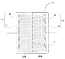
図1は、バナジウム固体塩電池の構成例を示している。
図1に示すように、バナジウム固体塩電池10は、イオン交換膜12によって仕切られた正極20及び負極30を備えている。正極20には、第1の集電体22が配置されている。負極30には、第2の集電体32が配置されている。第1の集電体22とイオン交換膜12の間には、第1の電極24が配置されている。第2の集電体32とイオン交換膜12の間には、第2の電極34が配置されている。正極20には、正極活物質であるオキシ硫酸バナジウム(IV)・n水和物と硫酸水溶液(電解液)とカーボンの混合物が充填されている。負極30には、負極活物質である硫酸バナジウム(III)・n水和物と硫酸水溶液(電解液)とカーボンの混合物が充填されている。第1の集電体22と第2の集電体32との間に適当な大きさの電気抵抗を接続することによって、電池の放電が行われる。第1の集電体22と第2の集電体32との間に十分な大きさの電圧を印加することによって、電池の充電が行われる。
図1に示すように、バナジウム固体塩電池10は、イオン交換膜12によって仕切られた正極20及び負極30を備えている。正極20には、第1の集電体22が配置されている。負極30には、第2の集電体32が配置されている。第1の集電体22とイオン交換膜12の間には、第1の電極24が配置されている。第2の集電体32とイオン交換膜12の間には、第2の電極34が配置されている。正極20には、正極活物質であるオキシ硫酸バナジウム(IV)・n水和物と硫酸水溶液(電解液)とカーボンの混合物が充填されている。負極30には、負極活物質である硫酸バナジウム(III)・n水和物と硫酸水溶液(電解液)とカーボンの混合物が充填されている。第1の集電体22と第2の集電体32との間に適当な大きさの電気抵抗を接続することによって、電池の放電が行われる。第1の集電体22と第2の集電体32との間に十分な大きさの電圧を印加することによって、電池の充電が行われる。
第1の集電体22は、例えば銅などの導電材料によって形成されている。あるいは、第1の集電体22は、例えば、導電性ゴム、導電性樹脂、DLC等によってコーティングされた金属箔によって形成されている。第1の集電体22の形状は、特に制限するものではないが、例えば平板状である。第1の集電体22の表面は、第1の電極24に接している。第1の集電体22が銅によって形成される場合、銅の表面が腐食されないように、銅の表面にカーボンがコーティングされてもよい。あるいは、銅の表面が腐食されないように、銅の表面にグラファイトシートが貼り付けられてもよい。
第2の集電体32は、例えば銅などの導電材料によって形成されている。あるいは、第2の集電体32は、例えば、導電性ゴム、導電性樹脂、DLC等によってコーティングされた金属箔によって形成されている。第2の集電体32の形状は、特に制限するものではないが、例えば平板状である。第2の集電体32の表面は、第2の電極34に接している。第2の集電体32が銅によって形成される場合、銅の表面が腐食されないように、銅の表面にカーボンがコーティングされてもよい。あるいは、銅の表面が腐食されないように、銅の表面にグラファイトシートが貼り付けられてもよい。
第1の電極24は、炭素材料によって形成されている。炭素材料としては、例えば、カーボンブラック、炭素繊維、カーボンナノチューブ、グラフェン、グラッシーカーボン(登録商標)の粉末、黒鉛粉末、多孔質カーボン粉末、活性炭、及び/又は、炭素フェルトを用いることができる。これらの炭素材料の中では、カーボンブラックが特に好ましい。
第1の電極24は、例えば、以下のように製造することができる。
上記した炭素材料、正極活物質、バインダー、及び電解液を混練した後に、この混練物を圧延することでシート状に成形する。このシート状の成形物を所定形状に打ち抜くことによって、第1の電極24を製造することができる。
バインダーとしては、例えば、PTFE、PVDF、フッ素系バインダー、ポリイミド、ポリアミド、ポリアミドイミド、ゴム系バインダー、アクリル系バインダー、塩素系バインダー、及び/又は、無機系バインダーを用いることができる。
上記した炭素材料、正極活物質、バインダー、及び電解液を混練した後に、この混練物を圧延することでシート状に成形する。このシート状の成形物を所定形状に打ち抜くことによって、第1の電極24を製造することができる。
バインダーとしては、例えば、PTFE、PVDF、フッ素系バインダー、ポリイミド、ポリアミド、ポリアミドイミド、ゴム系バインダー、アクリル系バインダー、塩素系バインダー、及び/又は、無機系バインダーを用いることができる。
第2の電極34は、炭素材料によって形成されている。炭素材料としては、例えば、カーボンブラック、炭素繊維、カーボンナノチューブ、グラフェン、グラッシーカーボン(登録商標)の粉末、黒鉛粉末、多孔質カーボン粉末、活性炭、及び/又は、炭素フェルトを用いることができる。これらの炭素材料の中では、カーボンブラックが特に好ましい。
第2の電極34は、例えば、以下のように製造することができる。
上記した炭素材料、負極活物質、バインダー、及び電解液を混練した後に、この混練物を圧延することでシート状に成形する。このシート状の成形物を所定形状に打ち抜くことによって、第2の電極34を製造することができる。
バインダーとしては、例えば、PTFE、PVDF、フッ素系バインダー、ポリイミド、ポリアミド、ポリアミドイミド、ゴム系バインダー、アクリル系バインダー、塩素系バインダー、及び/又は、無機系バインダーを用いることができる。
上記した炭素材料、負極活物質、バインダー、及び電解液を混練した後に、この混練物を圧延することでシート状に成形する。このシート状の成形物を所定形状に打ち抜くことによって、第2の電極34を製造することができる。
バインダーとしては、例えば、PTFE、PVDF、フッ素系バインダー、ポリイミド、ポリアミド、ポリアミドイミド、ゴム系バインダー、アクリル系バインダー、塩素系バインダー、及び/又は、無機系バインダーを用いることができる。
イオン交換膜12は、正極20及び負極30の間でバナジウムイオン以外のイオン(例えば、水素イオン、硫酸イオン等)を選択的に通過させることのできる膜である。イオン交換膜12は、硫酸イオン等の陰イオンを選択的に通過させることのできる陰イオン交換膜であることが好ましい。なお、イオン交換膜12は、バナジウムイオン以外のイオンを選択的に通過させることができるが、少量のバナジウムイオンを通過させてしまうこともある。
本実施形態のバナジウム固体塩電池10において、イオン交換膜12は、0.5M硫酸中での1kHzにおける膜抵抗値が2.0Ω・cm2以下であり、かつ、5価のバナジウムイオンの透過性が600μmol/(cm2・week)以下であることを特徴とする。
イオン交換膜12は、0.5M硫酸中での1kHzにおける膜抵抗値が1.0Ω・cm2以下であることが好ましい。
イオン交換膜12は、5価のバナジウムイオンの透過性が500μmol/(cm2・week)以下であることが好ましい。
イオン交換膜12の0.5M硫酸中での1kHzにおける膜抵抗値は、例えば、膜抵抗測定用H型セルと、日置電機株式会社製バッテリハイテスタBT3562-01を用いて測定することができる。
膜抵抗測定用H型セルの仕様は、例えば、以下の通りである。
有効膜寸法 : φ15 mm
有効膜面積 : 1.77 cm2
電極材質 : Pt(標準)
膜抵抗測定用H型セルの仕様は、例えば、以下の通りである。
有効膜寸法 : φ15 mm
有効膜面積 : 1.77 cm2
電極材質 : Pt(標準)
イオン交換膜12の0.5M硫酸中での1kHzにおける膜抵抗値は、以下の手順によって測定することができる。
まず、膜抵抗測定用H型セルを、2つのセルの間にイオン交換膜を挟まずに組み立てる。膜の両側のセルに、0.5M硫酸をそれぞれ充填する。膜の両側の電極に、バッテリハイテスタの端子を接続し、1kHzにおける交流抵抗値を測定する。この測定結果を、リファレンスとする。次に、膜抵抗測定用H型セルを解体した後、φ37mmにカットした測定対象となるイオン交換膜を2つのセルの間に挟んで、膜抵抗測定用H型セルを組み立てる。リファレンスの測定手順と同様に、1kHzにおける交流抵抗値を測定する。この測定結果と、リファレンスとの差を、イオン交換膜の抵抗値とする。
まず、膜抵抗測定用H型セルを、2つのセルの間にイオン交換膜を挟まずに組み立てる。膜の両側のセルに、0.5M硫酸をそれぞれ充填する。膜の両側の電極に、バッテリハイテスタの端子を接続し、1kHzにおける交流抵抗値を測定する。この測定結果を、リファレンスとする。次に、膜抵抗測定用H型セルを解体した後、φ37mmにカットした測定対象となるイオン交換膜を2つのセルの間に挟んで、膜抵抗測定用H型セルを組み立てる。リファレンスの測定手順と同様に、1kHzにおける交流抵抗値を測定する。この測定結果と、リファレンスとの差を、イオン交換膜の抵抗値とする。
イオン交換膜12の5価のバナジウムイオンの透過性は、以下の手順によって測定することができる。
(1)H型セルのフランジガラスセル同士の間に、隔膜として測定対象であるイオン交換膜を挟み込み、フランジ用固定クランプでフランジガラスセルを固定する。H型セルは、例えば、イーシーフロンティア社製のH型セル(型式名:VB-9)を用いることができる。フランジガラスセルにおけるフランジ部の内径は、12mmである。
(2)フランジガラスセルの片方の極に、バナジウム元素濃度が1M(mol/L)となる5価のバナジウムイオンと、遊離硫酸の濃度が2M(mol/L)となるだけの硫酸とを含む溶液を15mL入れ、対極に2M(mol/L)の硫酸を含む溶液を15mL入れる。硫酸溶液を入れた後、フランジガラスセルを25℃の環境に放置する。
(3)両方の極に硫酸溶液を入れてから1週間後に、5価のバナジウムイオンを入れてあった極から対極である2M硫酸が入っていた極に移動してきた5価のバナジウムイオンの濃度を測定する。バナジウムイオンの濃度の測定は、ICP発光分析装置(島津製作所社製ICPE-9000)により行うことができる。
(4)上記(3)で測定した濃度から、1週間当たりに膜の単位面積あたりで移動した5価のバナジウムイオンの物質量を算出する。
(1)H型セルのフランジガラスセル同士の間に、隔膜として測定対象であるイオン交換膜を挟み込み、フランジ用固定クランプでフランジガラスセルを固定する。H型セルは、例えば、イーシーフロンティア社製のH型セル(型式名:VB-9)を用いることができる。フランジガラスセルにおけるフランジ部の内径は、12mmである。
(2)フランジガラスセルの片方の極に、バナジウム元素濃度が1M(mol/L)となる5価のバナジウムイオンと、遊離硫酸の濃度が2M(mol/L)となるだけの硫酸とを含む溶液を15mL入れ、対極に2M(mol/L)の硫酸を含む溶液を15mL入れる。硫酸溶液を入れた後、フランジガラスセルを25℃の環境に放置する。
(3)両方の極に硫酸溶液を入れてから1週間後に、5価のバナジウムイオンを入れてあった極から対極である2M硫酸が入っていた極に移動してきた5価のバナジウムイオンの濃度を測定する。バナジウムイオンの濃度の測定は、ICP発光分析装置(島津製作所社製ICPE-9000)により行うことができる。
(4)上記(3)で測定した濃度から、1週間当たりに膜の単位面積あたりで移動した5価のバナジウムイオンの物質量を算出する。
本実施形態のバナジウム固体塩電池10によれば、電池の高寿命化及び高出力化を達成することができる。
以下、本発明の実施例について具体的に説明する。
実施例では、以下の8種類のイオン交換膜を使用した。
A:FuMA-Tech社製、VX-20、膜厚20μm
B:FuMA-Tech社製、VX-10、膜厚10μm
C:FuMA-Tech社製、VPMX-310、膜厚10μm
D:FuMA-Tech社製、VPMX-320、膜厚20μm
E:FuMA-Tech社製、VPMX-20、膜厚20μm
F:AGCエンジニアリング株式会社製、AMV、膜厚120μm
G:AGCエンジニアリング株式会社製、AMT、膜厚200μm
H:株式会社アストム製、AFX、膜厚170μm
実施例では、以下の8種類のイオン交換膜を使用した。
A:FuMA-Tech社製、VX-20、膜厚20μm
B:FuMA-Tech社製、VX-10、膜厚10μm
C:FuMA-Tech社製、VPMX-310、膜厚10μm
D:FuMA-Tech社製、VPMX-320、膜厚20μm
E:FuMA-Tech社製、VPMX-20、膜厚20μm
F:AGCエンジニアリング株式会社製、AMV、膜厚120μm
G:AGCエンジニアリング株式会社製、AMT、膜厚200μm
H:株式会社アストム製、AFX、膜厚170μm
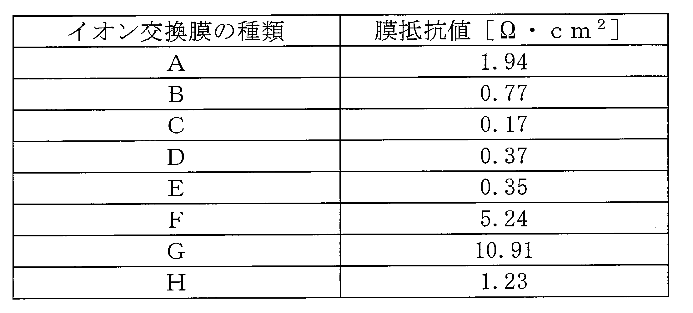
上記8種類のイオン交換膜(A~H)の0.5M硫酸中での1kHzにおける膜抵抗値を、上記で説明した方法によって測定した。測定結果を以下の表1に示す。
上記8種類のイオン交換膜(A~H)の5価のバナジウムイオンの透過性を、上記で説明した手順によって測定した。測定結果を以下の表2に示す。
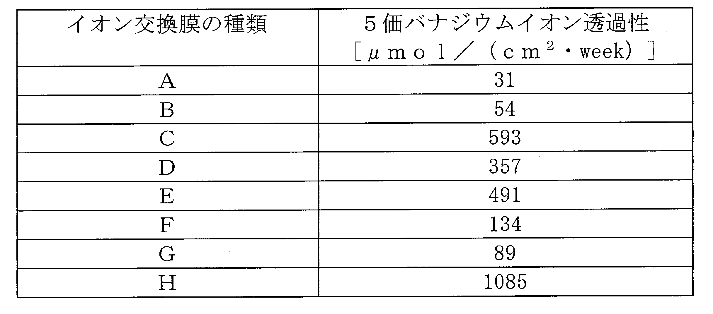
0.5M硫酸中での1kHzにおける膜抵抗値が2.0Ω・cm2以下であり、かつ、5価のバナジウムイオンの透過性が600μmol/(cm2・week)以下であるという条件を満たすイオン交換膜は、A~Eである。つまり、以下に説明する、イオン交換膜A~Eを用いて作製したバナジウム固体塩電池は、本発明の実施例に対応する。イオン交換膜F~Hを用いて作製したバナジウム固体塩電池は、本発明の比較例に対応する。
A~Eのうち、0.5M硫酸中での1kHzにおける膜抵抗値が1.0Ω・cm2以下であるという条件を満たすイオン交換膜は、B~Eである。
A~Eのうち、5価のバナジウムイオンの透過性が500μmol/(cm2・week)以下であるという条件を満たすイオン交換膜は、A、B、D、Eである。
(バナジウム固体塩電池の作製)
つぎに、イオン交換膜A~Hを用いて、バナジウム固体塩電池を作製した。
正極及び負極に用いた電極の組成は、以下の表3に記載の通りである。
つぎに、イオン交換膜A~Hを用いて、バナジウム固体塩電池を作製した。
正極及び負極に用いた電極の組成は、以下の表3に記載の通りである。

(放電レート特性の測定)
イオン交換膜A~Hを用いて作製したバナジウム固体塩電池の放電レート特性を測定した。
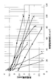
具体的には、一定の電流密度で開始電圧1.45Vから終止電圧1.20Vまで電池を放電させたときの放電容量を測定した。同一の電池を用いて電流密度を変化させて同様の実験を繰り返し、横軸に放電電流密度(mA/cm2)、縦軸に放電容量(mAh)をプロットしたグラフを作成した。イオン交換膜A~Hを用いて作製した全てのバナジウム固体塩電池について、同様の測定を行った。結果を図2に示す。
イオン交換膜A~Hを用いて作製したバナジウム固体塩電池の放電レート特性を測定した。
具体的には、一定の電流密度で開始電圧1.45Vから終止電圧1.20Vまで電池を放電させたときの放電容量を測定した。同一の電池を用いて電流密度を変化させて同様の実験を繰り返し、横軸に放電電流密度(mA/cm2)、縦軸に放電容量(mAh)をプロットしたグラフを作成した。イオン交換膜A~Hを用いて作製した全てのバナジウム固体塩電池について、同様の測定を行った。結果を図2に示す。
図2に示すグラフは、イオン交換膜A~Hを用いて作製したバナジウム固体塩電池の放電レート特性を示している。図2に示すグラフにおいて、グラフの傾きが大きい(グラフが水平に近い)ほど、そのグラフに対応する電池の放電レート特性は優れている。グラフの傾きが大きいほど、放電電流密度が大きくなった場合でも、放電容量があまり低下しないことを意味するからである。図2を見れば分かる通り、電池の放電レート特性が優れているのは、イオン交換膜A~Eを用いて作製したバナジウム固体塩電池である。
(放電容量維持率の算出)
以下の数式(1)により、放電容量維持率を算出した。結果を以下の表4に示す。
以下の数式(1)により、放電容量維持率を算出した。結果を以下の表4に示す。
放電容量維持率(%)={放電電流密度が50(mA/cm2)のときの放電容量(mAh)/放電電流密度が2.5(mA/cm2)のときの放電容量(mAh)}×100 … 数式(1)

表4を見れば分かる通り、放電容量維持率が優れているのは、イオン交換膜B~Eを用いて作製したバナジウム固体塩電池である。イオン交換膜B~Eは、0.5M硫酸中での1kHzにおける膜抵抗値が1.0Ω・cm2以下であり、かつ、5価のバナジウムイオンの透過性が40μmol/(cm2・week)~600μmol/(cm2・week)であるという条件を満たすイオン交換膜である。
(自己放電特性の測定)
イオン交換膜A~Hを用いて作製したバナジウム固体塩電池の自己放電特性を測定した。具体的には、正極と負極とを接続しないで電池を放置したときの自己放電時間及び電圧を測定した。結果を図3に示す。
イオン交換膜A~Hを用いて作製したバナジウム固体塩電池の自己放電特性を測定した。具体的には、正極と負極とを接続しないで電池を放置したときの自己放電時間及び電圧を測定した。結果を図3に示す。
図3に示すグラフは、イオン交換膜A~Hを用いて作製したバナジウム固体塩電池の自己放電特性を示している。図3に示すグラフにおいて、グラフの傾きが大きい(グラフが水平に近い)ほど、そのグラフに対応する電池の自己放電特性は優れている。グラフの傾きが大きいほど、電池があまり自己放電することなく、電池を放置した場合でも電池の電圧があまり低下しないことを意味するからである。図3を見れば分かる通り、電池の自己放電特性が優れているのは、イオン交換膜A、B、D、E、F、Gを用いて作製したバナジウム固体塩電池である。イオン交換膜A、B、D、E、F、Gは、0.5M硫酸中での1kHzにおける膜抵抗値が0.3Ω・cm2以上であり、かつ、5価のバナジウムイオンの透過性が600μmol/(cm2・week)以下であるという条件を満たすイオン交換膜である。
(80時間自己放電後の電圧維持率の測定)
イオン交換膜A~Hを用いて作製したバナジウム固体塩電池を80時間自己放電させたときの電圧を測定した。そして、以下の数式(2)により、80時間自己放電後の電圧維持率を算出した。結果を以下の表5に示す。
イオン交換膜A~Hを用いて作製したバナジウム固体塩電池を80時間自己放電させたときの電圧を測定した。そして、以下の数式(2)により、80時間自己放電後の電圧維持率を算出した。結果を以下の表5に示す。
電圧維持率(%)={80時間自己放電後の電圧(V)/自己放電開始時の電圧(V)}×100 … 数式(2)

表5を見ればわかる通り、80時間自己放電後の電圧維持率が優れているのは、イオン交換膜A、B、D、E、F、Gを用いて作製したバナジウム固体塩電池である。
以上の実施例より、0.5M硫酸中での1kHzにおける膜抵抗値が2.0Ω・cm2以下であり、かつ、5価のバナジウムイオンの透過性が600μmol/(cm2・week)以下であるという条件を満たすイオン交換膜(A~E)を用いて作製されたバナジウム固体塩電池は、放電レート特性に優れており、自己放電特性にも優れていることを実証することができた。
イオン交換膜の膜抵抗値が小さいということは、イオン交換膜をバナジウムイオン以外のイオンが通過しやすいことを意味する。しかし、イオン交換膜の膜抵抗値が小さすぎる場合、電池の機能の観点からは通過させるべきではないバナジウムイオンまでもがイオン交換膜を通過してしまう。この場合、正極と負極の間をバナジウムイオンが移動するため、バナジウム固体塩電池の80時間自己放電後電圧維持率が悪化してしまう。
したがって、イオン交換膜の膜抵抗値は、0.3[Ω・cm2]以上であることが好ましい。膜抵抗値が0.3[Ω・cm2]以上であるイオン交換膜を用いてバナジウム固体塩電池を作製することによって、80時間自己放電後電圧維持率にも優れるバナジウム固体塩電池を実現することができる。
したがって、イオン交換膜の膜抵抗値は、0.3[Ω・cm2]以上であることが好ましい。膜抵抗値が0.3[Ω・cm2]以上であるイオン交換膜を用いてバナジウム固体塩電池を作製することによって、80時間自己放電後電圧維持率にも優れるバナジウム固体塩電池を実現することができる。
イオン交換膜の5価バナジウムイオン透過性が小さいということは、イオン交換膜を5価バナジウムイオンが通過しにくいことを意味する。しかし、イオン交換膜の5価バナジウムイオン透過性が小さすぎる場合、電池の機能の観点からは通過させるべきであるバナジウムイオン以外のイオン(水素イオンや硫酸イオン)までもがイオン交換膜を通過できなくなってしまう。この場合、正極と負極の間をバナジウムイオン以外のイオンが移動できなくなるため、バナジウム固体塩電池の放電容量維持率が悪化してしまう。
したがって、イオン交換膜の5価バナジウムイオン透過性は、40μmol/ (cm2・week)以上であることが好ましい。5価バナジウムイオン透過性が40μmol/(cm2・week)以上であるイオン交換膜を用いてバナジウム固体塩電池を作製することによって、放電容量維持率にも優れるバナジウム固体塩電池を実現することができる。
したがって、イオン交換膜の5価バナジウムイオン透過性は、40μmol/ (cm2・week)以上であることが好ましい。5価バナジウムイオン透過性が40μmol/(cm2・week)以上であるイオン交換膜を用いてバナジウム固体塩電池を作製することによって、放電容量維持率にも優れるバナジウム固体塩電池を実現することができる。
10 バナジウム固体塩電池(バナジウムレドックス電池)
12 イオン交換膜
20 正極
22 第1の集電体
24 第1の電極
30 負極
32 第2の集電体
34 第2の電極
12 イオン交換膜
20 正極
22 第1の集電体
24 第1の電極
30 負極
32 第2の集電体
34 第2の電極
Claims (5)
- バナジウムレドックス電池であって、
酸化還元反応によって、5価及び4価の間で酸化数が変化するバナジウムイオン又は5価及び4価の間で酸化数が変化するバナジウムを含む陽イオンを含有する正極活物質を含む正極と、
酸化還元反応によって、2価及び3価の間で酸化数が変化するバナジウムイオン又は2価及び3価の間で酸化数が変化するバナジウムを含む陽イオンを含有する負極活物質を含む負極と、
正極と負極とを区画するとともに、水素イオンを通過させるイオン交換膜と、を含み、
前記イオン交換膜は、0.5M硫酸中での1kHzにおける膜抵抗値が2.0Ω・cm2以下であり、かつ、5価のバナジウムイオンの透過性が600μmol/(cm2・week)以下である、バナジウムレドックス電池。 - 前記イオン交換膜は、5価のバナジウムイオンの透過性が500μmol/(cm2・week)以下である、請求項1に記載のバナジウムレドックス電池。
- 前記イオン交換膜は、0.5M硫酸中での1kHzにおける膜抵抗値が1.0Ω・cm2以下である、請求項1または請求項2に記載のバナジウムレドックス電池。
- 前記イオン交換膜は、0.5M硫酸中での1kHzにおける膜抵抗値が0.3Ω・cm2以上である、請求項1~3のいずれか一項に記載のバナジウムレドックス電池。
- 前記イオン交換膜は、5価のバナジウムイオンの透過性が40μmol/(cm2・week)以上である、請求項1~4のいずれか一項に記載のバナジウムレドックス電池。
Applications Claiming Priority (2)
| Application Number | Priority Date | Filing Date | Title |
|---|---|---|---|
| JP2015-073341 | 2015-03-31 | ||
| JP2015073341A JP2016194974A (ja) | 2015-03-31 | 2015-03-31 | バナジウムレドックス電池 |
Publications (1)
| Publication Number | Publication Date |
|---|---|
| WO2016158217A1 true WO2016158217A1 (ja) | 2016-10-06 |
Family
ID=57004194
Family Applications (1)
| Application Number | Title | Priority Date | Filing Date |
|---|---|---|---|
| PCT/JP2016/056981 Ceased WO2016158217A1 (ja) | 2015-03-31 | 2016-03-07 | バナジウムレドックス電池 |
Country Status (2)
| Country | Link |
|---|---|
| JP (1) | JP2016194974A (ja) |
| WO (1) | WO2016158217A1 (ja) |
Cited By (2)
| Publication number | Priority date | Publication date | Assignee | Title |
|---|---|---|---|---|
| WO2017203921A1 (ja) * | 2016-05-25 | 2017-11-30 | ブラザー工業株式会社 | バナジウムレドックス二次電池、及びバナジウムレドックス二次電池の製造方法 |
| CN115198329A (zh) * | 2021-04-09 | 2022-10-18 | 国家能源投资集团有限责任公司 | 液流电池用无机氧化铝膜和复合膜及其制备方法和液流电池 |
Families Citing this family (1)
| Publication number | Priority date | Publication date | Assignee | Title |
|---|---|---|---|---|
| JP7576399B2 (ja) * | 2020-02-05 | 2024-10-31 | 三井化学株式会社 | イオン交換膜 |
Citations (4)
| Publication number | Priority date | Publication date | Assignee | Title |
|---|---|---|---|---|
| JPH10208767A (ja) * | 1996-11-22 | 1998-08-07 | Tokuyama Corp | バナジウム系レドックスフロー電池用隔膜及びその製造方法 |
| JP2006147374A (ja) * | 2004-11-19 | 2006-06-08 | Kansai Electric Power Co Inc:The | バナジウムレドックスフロー電池システムの運転方法 |
| JP2008027627A (ja) * | 2006-07-18 | 2008-02-07 | Kansai Electric Power Co Inc:The | レドックスフロー電池用隔膜 |
| WO2014126179A1 (ja) * | 2013-02-18 | 2014-08-21 | ブラザー工業株式会社 | バナジウム固体塩電池及びその製造方法 |
-
2015
- 2015-03-31 JP JP2015073341A patent/JP2016194974A/ja active Pending
-
2016
- 2016-03-07 WO PCT/JP2016/056981 patent/WO2016158217A1/ja not_active Ceased
Patent Citations (4)
| Publication number | Priority date | Publication date | Assignee | Title |
|---|---|---|---|---|
| JPH10208767A (ja) * | 1996-11-22 | 1998-08-07 | Tokuyama Corp | バナジウム系レドックスフロー電池用隔膜及びその製造方法 |
| JP2006147374A (ja) * | 2004-11-19 | 2006-06-08 | Kansai Electric Power Co Inc:The | バナジウムレドックスフロー電池システムの運転方法 |
| JP2008027627A (ja) * | 2006-07-18 | 2008-02-07 | Kansai Electric Power Co Inc:The | レドックスフロー電池用隔膜 |
| WO2014126179A1 (ja) * | 2013-02-18 | 2014-08-21 | ブラザー工業株式会社 | バナジウム固体塩電池及びその製造方法 |
Non-Patent Citations (1)
| Title |
|---|
| DOKYOUNG KIM ET AL.: "Test of ionic exchange membrane for Vanadium redox flow battery", KIST EUROPE ANNUAL REPORT 2013, 2013, pages 89, XP055320361, Retrieved from the Internet <URL:URL:http://www.kist-europe.com/index.php/en/publication/ect-3?task=document.viewdoc&id=80> [retrieved on 20160523] * |
Cited By (2)
| Publication number | Priority date | Publication date | Assignee | Title |
|---|---|---|---|---|
| WO2017203921A1 (ja) * | 2016-05-25 | 2017-11-30 | ブラザー工業株式会社 | バナジウムレドックス二次電池、及びバナジウムレドックス二次電池の製造方法 |
| CN115198329A (zh) * | 2021-04-09 | 2022-10-18 | 国家能源投资集团有限责任公司 | 液流电池用无机氧化铝膜和复合膜及其制备方法和液流电池 |
Also Published As
| Publication number | Publication date |
|---|---|
| JP2016194974A (ja) | 2016-11-17 |
Similar Documents
| Publication | Publication Date | Title |
|---|---|---|
| CN102668224B (zh) | 钒电池 | |
| JP5988269B2 (ja) | バナジウム固体塩電池 | |
| JP2014130778A (ja) | 静止型バナジウムレドックス電池 | |
| JP7016503B2 (ja) | 二次電池 | |
| JP2017117752A (ja) | レドックスフロー電池 | |
| JP6176761B2 (ja) | バナジウム固体塩電池 | |
| US20150357653A1 (en) | Vanadium Solid-Salt Battery and Method for Producing Same | |
| JP5979551B2 (ja) | バナジウムレドックス電池 | |
| JP2016194974A (ja) | バナジウムレドックス電池 | |
| JP2015062177A (ja) | バナジウム電解質、その製造方法及びバナジウムレドックス電池 | |
| WO2016158295A1 (ja) | バナジウムレドックス電池 | |
| WO2016158216A1 (ja) | バナジウムレドックス電池 | |
| WO2014156595A1 (ja) | バナジウム固体塩電池及びその製造方法 | |
| KR101514881B1 (ko) | 이차전지용 전해액 제조방법 | |
| JP2016186853A (ja) | バナジウムレドックス電池 | |
| JP7759680B1 (ja) | バナジウム固体電池 | |
| JP2016192255A (ja) | バナジウムレドックス電池 | |
| JP6083566B2 (ja) | バナジウム固体塩電池及びその製造方法 | |
| WO2018029991A1 (ja) | バナジウムレドックス二次電池、及び電池用イオン伝導性膜 | |
| Darling et al. | Pseudo-steady-state flow battery experiments | |
| JP2017212104A (ja) | バナジウムレドックス二次電池、及びバナジウムレドックス二次電池の製造方法 | |
| WO2018055857A1 (ja) | バナジウムレドックス二次電池、及びバナジウムレドックス二次電池用隔膜 | |
| JP2018166092A (ja) | バナジウムレドックス二次電池、隔膜の製造方法、バナジウムレドックス二次電池の製造方法、及び隔膜 | |
| JP2017183017A (ja) | バナジウムレドックス二次電池 | |
| WO2017203920A1 (ja) | バナジウムレドックス二次電池 |
Legal Events
| Date | Code | Title | Description |
|---|---|---|---|
| 121 | Ep: the epo has been informed by wipo that ep was designated in this application |
Ref document number: 16772101 Country of ref document: EP Kind code of ref document: A1 |
|
| NENP | Non-entry into the national phase |
Ref country code: DE |
|
| 122 | Ep: pct application non-entry in european phase |
Ref document number: 16772101 Country of ref document: EP Kind code of ref document: A1 |