WO2016158162A1 - 遠心式ポンプ装置 - Google Patents
遠心式ポンプ装置 Download PDFInfo
- Publication number
- WO2016158162A1 WO2016158162A1 PCT/JP2016/056219 JP2016056219W WO2016158162A1 WO 2016158162 A1 WO2016158162 A1 WO 2016158162A1 JP 2016056219 W JP2016056219 W JP 2016056219W WO 2016158162 A1 WO2016158162 A1 WO 2016158162A1
- Authority
- WO
- WIPO (PCT)
- Prior art keywords
- impeller
- permanent magnet
- dynamic pressure
- chamber
- wall
- Prior art date
- Legal status (The legal status is an assumption and is not a legal conclusion. Google has not performed a legal analysis and makes no representation as to the accuracy of the status listed.)
- Ceased
Links
Images


Classifications
-
- F—MECHANICAL ENGINEERING; LIGHTING; HEATING; WEAPONS; BLASTING
- F04—POSITIVE - DISPLACEMENT MACHINES FOR LIQUIDS; PUMPS FOR LIQUIDS OR ELASTIC FLUIDS
- F04D—NON-POSITIVE-DISPLACEMENT PUMPS
- F04D13/00—Pumping installations or systems
- F04D13/02—Units comprising pumps and their driving means
- F04D13/06—Units comprising pumps and their driving means the pump being electrically driven
-
- F—MECHANICAL ENGINEERING; LIGHTING; HEATING; WEAPONS; BLASTING
- F04—POSITIVE - DISPLACEMENT MACHINES FOR LIQUIDS; PUMPS FOR LIQUIDS OR ELASTIC FLUIDS
- F04D—NON-POSITIVE-DISPLACEMENT PUMPS
- F04D29/00—Details, component parts, or accessories
-
- F—MECHANICAL ENGINEERING; LIGHTING; HEATING; WEAPONS; BLASTING
- F04—POSITIVE - DISPLACEMENT MACHINES FOR LIQUIDS; PUMPS FOR LIQUIDS OR ELASTIC FLUIDS
- F04D—NON-POSITIVE-DISPLACEMENT PUMPS
- F04D29/00—Details, component parts, or accessories
- F04D29/04—Shafts or bearings, or assemblies thereof
- F04D29/046—Bearings
- F04D29/047—Bearings hydrostatic; hydrodynamic
-
- F—MECHANICAL ENGINEERING; LIGHTING; HEATING; WEAPONS; BLASTING
- F04—POSITIVE - DISPLACEMENT MACHINES FOR LIQUIDS; PUMPS FOR LIQUIDS OR ELASTIC FLUIDS
- F04D—NON-POSITIVE-DISPLACEMENT PUMPS
- F04D29/00—Details, component parts, or accessories
- F04D29/04—Shafts or bearings, or assemblies thereof
- F04D29/046—Bearings
- F04D29/048—Bearings magnetic; electromagnetic
-
- H—ELECTRICITY
- H02—GENERATION; CONVERSION OR DISTRIBUTION OF ELECTRIC POWER
- H02K—DYNAMO-ELECTRIC MACHINES
- H02K21/00—Synchronous motors having permanent magnets; Synchronous generators having permanent magnets
- H02K21/12—Synchronous motors having permanent magnets; Synchronous generators having permanent magnets with stationary armatures and rotating magnets
- H02K21/24—Synchronous motors having permanent magnets; Synchronous generators having permanent magnets with stationary armatures and rotating magnets with magnets axially facing the armatures, e.g. hub-type cycle dynamos
-
- H—ELECTRICITY
- H02—GENERATION; CONVERSION OR DISTRIBUTION OF ELECTRIC POWER
- H02K—DYNAMO-ELECTRIC MACHINES
- H02K7/00—Arrangements for handling mechanical energy structurally associated with dynamo-electric machines, e.g. structural association with mechanical driving motors or auxiliary dynamo-electric machines
- H02K7/08—Structural association with bearings
Definitions
- the present invention relates to a centrifugal pump device, and more particularly to a centrifugal pump device provided with an impeller that sends a liquid by a centrifugal force during rotation.
- a canned motor having a structure in which a motor drive chamber and a rotor chamber are separated by a partition wall is often used.
- Such a motor is used, for example, in a pump for transporting pure water in a semiconductor production line used in an environment where dust is not desired or a pump for transporting biological fluid.
- Patent Document 1 JP 2010-261394 A (Patent Document 1) describes an axial gap type centrifugal pump characterized by non-contact floating of an impeller by a fluid dynamic pressure bearing and a canned motor structure.
- a ring shape is formed on the opposite side of the impeller so as to cancel the axial suction force acting between the impeller and the motor. Balance of attractive force in the axial direction by permanent magnets.
- the attractive force by these permanent magnets or the like is a component of negative rigidity (unstable element) that tends to approach the impeller more in one direction.
- negative rigidity unstable element
- the impeller is eccentric from the rotation center of the motor in the radial direction.
- this centrifugal pump has an impeller that deviates from the normal levitation position due to disturbance and fluid force due to the mutual balance of the axial suction force on the drive motor side and the axial suction force on the ring magnet side to offset it. May end up.
- Patent Document 1 As described above, as a method for controlling the axial attractive force changed due to the eccentricity of the impeller, in Japanese Patent Application Laid-Open No. 2010-261394 (Patent Document 1), the motor-side attractive force is balanced with the attractive force change of the ring-shaped magnet portion. In addition, the motor current phase was adjusted. As a result, even if the impeller is eccentric in the radial direction due to disturbances or operating conditions, stable rotation can be maintained without changing the floating position of the impeller in the axial direction.
- changing the motor current phase may cause various problems. For example, if the current phase changes from the situation where the motor is operated at the maximum efficiency point, the motor efficiency may be reduced. Further, for example, when the current phase is changed from the situation where the operation is performed at the maximum torque point, the generated torque is reduced, and there is a possibility that the pump output is reduced or the motor is stepped out.
- the present invention has been made to solve the above-described problems, and an object thereof is to provide a centrifugal pump device capable of achieving both prevention of contamination and prevention of reduction in efficiency and performance. .
- the present invention is a centrifugal pump device comprising a housing, an impeller, a drive unit, a plurality of first permanent magnets, and ring-shaped second to fifth permanent magnets.
- the housing includes first and second chambers separated by a partition wall.
- the impeller is rotatably provided with an axis that intersects the partition wall as a rotation axis in the first chamber, and sends liquid by centrifugal force during rotation.
- the driving unit is provided in the second chamber and rotates the impeller through the partition wall.
- the plurality of first permanent magnets are provided on one surface of the impeller along the partition and are disposed along the same circle.
- the drive unit includes a plurality of air-core coils that are provided to face the plurality of first permanent magnets and generate a rotating magnetic field.
- a first dynamic pressure groove is formed on the other surface opposite to the one surface of the impeller or on the inner wall of the first chamber facing the other surface.
- a second dynamic pressure groove is formed on one surface of the impeller or a partition wall facing the one surface.
- the ring-shaped second permanent magnet is disposed on one surface of the impeller.
- the ring-shaped third permanent magnet is disposed on the other surface of the impeller.
- the ring-shaped fourth permanent magnet is provided on the partition wall and faces the second permanent magnet.
- the ring-shaped fifth permanent magnet is provided on the inner wall of the first chamber and faces the third permanent magnet.
- the second permanent magnet and the fourth permanent magnet are arranged so that the magnetic poles of the opposing surfaces are different.
- the third permanent magnet and the fifth permanent magnet are arranged so that the magnetic poles of the opposing surfaces are different.
- the coil of the drive unit has a coreless structure so that the axial suction force does not work.
- a configuration has been realized in which ring-shaped permanent magnets that have been arranged so as to offset the axial attractive force acting between the impeller and the motor can be arranged on both sides of the impeller, and the radial support force has been improved.
- Directional disturbance resistance can be increased.
- the driving unit further includes a magnetic body that is disposed on the side opposite to the partition walls of the plurality of air-core coils and is magnetically coupled to the plurality of air-core coils.
- the second and third permanent magnets are provided on the outer peripheral portions of one surface and the other surface of the impeller, respectively.
- the fourth permanent magnet is provided on the outer peripheral portion of the partition wall, and the fifth permanent magnet is provided on the outer peripheral portion of the inner wall of the first chamber.
- the second and third permanent magnets are provided on the inner peripheral portion of one surface and the other surface of the impeller, respectively.
- the fourth permanent magnet is provided on the inner peripheral portion of the partition wall, and the fifth permanent magnet is provided on the inner peripheral portion of the inner wall of the first chamber.
- a third dynamic pressure groove is formed on the outer peripheral surface of the impeller or the outer peripheral surface of the first chamber facing the impeller, or the inner peripheral surface of the impeller or the inner peripheral surface of the first chamber facing the impeller.
- the supporting force in the radial direction can be increased.
- the plurality of first permanent magnets are arranged along the same circle such that adjacent magnetic poles are different from each other.
- the attractive force on the drive motor side and the negative stiffness component in the axial direction of the attractive force on the ring magnet side to cancel it cause instability of the impeller behavior.
- the coil of the drive unit is an air-core coil so that the axial suction force from the drive unit does not act on the impeller.
- the ring-shaped permanent magnets that have been arranged to offset the axial attractive force in the conventional structure are designed for exclusive use to strengthen the radial support force, thereby enabling stable impeller rotation and rotation. It is.
- the cogging torque of the motor is reduced, so that the impeller can be started and rotated smoothly, and the restoring force in the radial direction is also increased, thereby improving the disturbance resistance of the impeller.
- FIG. 3 is a diagram showing a detailed arrangement of magnets embedded in a shroud of the impeller 10.
- FIG. 6 is a sectional view taken along line VI-VI in FIG. 3. It is the elements on larger scale which showed arrangement
- FIG. 6 is sectional drawing which shows the state which removed the impeller 10 from FIG. FIG.
- FIG. 4 is a cross-sectional view showing a state where an impeller is removed from the cross-sectional view taken along the line IX-IX in FIG. 3. It is a 1st modification of arrangement
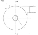
- FIG. 1 is a front view showing an appearance of a pump unit 1 of a centrifugal pump device according to an embodiment of the present invention.
- FIG. 2 is a side view of the pump unit 1 shown in FIG. 3 is a cross-sectional view taken along line III-III in FIG. 4 is a cross-sectional view taken along line IV-IV in FIG.
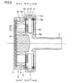
- the pump unit 1 of the centrifugal pump device includes a housing 2 formed of a nonmagnetic material.
- the housing 2 includes a columnar main body 3, a cylindrical inflow port 4 erected at the center of one end surface of the main body 3, and a cylindrical outflow port 5 provided on the outer peripheral surface of the main body 3. Including.
- the outflow port 5 extends in the tangential direction of the outer peripheral surface of the main body 3.
- a pump chamber 7 and a motor chamber 8 partitioned by a partition wall 6 are provided in the housing 2, as shown in FIG. 3, a pump chamber 7 and a motor chamber 8 partitioned by a partition wall 6 are provided.
- a disc-shaped impeller 10 having a through hole 10 a at the center is rotatably provided in the pump chamber 7.
- the impeller 10 includes two shrouds 11 and 12 each having a donut plate shape and a plurality of (for example, six) vanes 13 formed between the two shrouds 11 and 12.
- the shroud 11 is disposed on the inflow port 4 side, and the shroud 12 is disposed on the partition wall 6 side.
- the shrouds 11 and 12 and the vane 13 are made of a nonmagnetic material.
- a plurality of (in this case, six) passages 14 partitioned by a plurality of vanes 13 are formed between the two shrouds 11 and 12.
- the passage 14 communicates with the central through hole 10 a of the impeller 10, and starts from the through hole 10 a of the impeller 10 and extends so that the width gradually increases to the outer peripheral edge.
- the vane 13 is formed between two adjacent passages 14.
- the plurality of vanes 13 are provided at equiangular intervals and formed in the same shape. Therefore, the plurality of passages 14 are provided at equiangular intervals and are formed in the same shape.
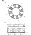
- FIG. 5 is a diagram showing a detailed arrangement of the magnets embedded in the shroud of the impeller 10.
- a plurality of (for example, eight) permanent magnets 17 are embedded in shroud 12.
- the plurality of permanent magnets 17 are arranged with gaps along the same circle at equal angular intervals so that adjacent magnetic poles are different from each other.
- the permanent magnet 17 with the N pole facing the motor chamber 8 side and the permanent magnet 17 with the S pole facing the motor chamber 8 side are alternately provided along the same circle with gaps provided at equal angular intervals. Has been placed.
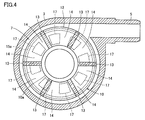
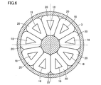
- FIG. 6 is a cross-sectional view taken along line VI-VI in FIG.
- a plurality of (for example, nine) air-core coils 20 are provided in the motor chamber 8.
- the plurality of air-core coils 20 are arranged along the same circle at equal angular intervals so as to face the plurality of permanent magnets 17 of the impeller 10 with a partition wall interposed therebetween.
- a coil wiring is wound around an air-core portion 18 on which no magnetic material or the like is disposed.
- a magnetic body 19 serving as a back yoke is arranged on the side opposite to the partition walls of the plurality of air-core coils, and the magnetic flux of the air-core coil 20 is strengthened.
- the back yoke may not be provided.
- the voltage is applied to the nine air-core coils 20 by, for example, a 120-degree energization method. That is, nine air-core coils 20 are grouped by three.
- the U-phase, V-phase, and W-phase three-phase voltages VU, VV, and VW are applied to the first to third air-core coils 20 of each group.
- a positive voltage is applied to the first air-core coil 20 during a period of 0 to 120 degrees
- 0 V is applied during a period of 120 to 180 degrees
- a negative voltage is applied during a period of 180 to 300 degrees
- 300 to 0V is applied during a period of 360 degrees.
- the front end face (end face on the impeller 10 side) of the first air-core coil 20 becomes the N pole during the period of 0 to 120 degrees and becomes the S pole during the period of 180 to 300 degrees.
- the phase of the voltage VV is 120 degrees behind the voltage VU
- the phase of the voltage VW is 120 degrees behind the voltage VV. Therefore, by applying the voltages VU, VV, and VW to the first to third air-core coils 20, respectively, a rotating magnetic field can be formed, and the plurality of air-core coils 20 and the plurality of permanent magnets 17 of the impeller 10 can be formed.
- the impeller 10 can be rotated by the suction force and the repulsive force.
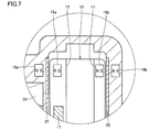
- FIG. 7 is a partially enlarged view showing the arrangement of the ring-shaped magnets of FIG.
- pump unit 1 includes ring-shaped permanent magnets 15a, 15b, 16a, 16b.
- ring-shaped permanent magnets 15 a and 15 b are embedded in the impeller 10
- ring-shaped permanent magnets 16 a and 16 b are embedded in the housing 2 so as to face each other.
- the impeller 10 is supported by ring-shaped permanent magnets 15 a and 15 b embedded in both surfaces (the shrouds 11 and 12) of the impeller 10 as shown in the partially enlarged portion of FIG. 7.
- the ring-shaped permanent magnets 15a and 15b and the ring-shaped permanent magnets 16a and 16b facing each other are arranged in the direction of the magnetic poles so that the axial attractive force acts on each other.
- the ring-shaped permanent magnet 15a is arranged such that the N pole is on the ring-shaped permanent magnet 16a side, and the S-pole is on the ring-shaped permanent magnet 15a side. Arrange as follows.
- the ring-shaped permanent magnet 15b is disposed so that the S pole is on the ring-shaped permanent magnet 16b side, and the ring-shaped permanent magnet 16b is disposed so that the N-pole is on the ring-shaped permanent magnet 15a side. Note that the magnetic poles may be reversed as appropriate.
- the ring magnet pair (15a, 16a) and the ring magnet pair (15b, 16b) on both sides of the impeller 10 have the same axial suction force (the difference in suction force is zero at the center floating position of the impeller 10).
- the impeller 10 can be stably rotated.
- the restoring force for returning the impeller 10 to the center position of the pump chamber 7 by the ring-shaped permanent magnets 15a, 15b, 16a, 16b becomes strong.
- the ring-shaped permanent magnets can be arranged on both surfaces of the impeller 10 so that the attractive force can be offset by both.
- the ring-shaped permanent magnet has a role of supporting the radial direction of the impeller 10, and the support force in the radial direction can be increased by arranging the ring-shaped permanent magnet on both surfaces of the impeller 10.
- the ring-shaped permanent magnets have a dedicated arrangement that strengthens the support force in the radial direction, enabling the impeller to stably float and rotate. As a result, the cogging torque of the motor is reduced, and the impeller can be started and rotated smoothly. Furthermore, the radial restoring force also increases, which increases the disturbance resistance of the impeller.
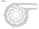
- FIG. 8 is a cross-sectional view showing a state where the impeller is removed from FIG. 4.
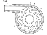
- FIG. 9 is a cross-sectional view showing a state where the impeller is removed from the cross-sectional view taken along the line IX-IX in FIG.
- a plurality of dynamic pressure grooves 21 are formed on the surface of the partition wall 6 facing the shroud 12 of the impeller 10, and a plurality of dynamic pressures are formed on the inner wall of the pump chamber 7 facing the shroud 11.
- a groove 22 is formed.
- the plurality of dynamic pressure grooves 21 are formed in a size corresponding to the shroud 12 of the impeller 10, as shown in FIG.
- Each dynamic pressure groove 21 has one end on the periphery (circumference) of a circular portion slightly spaced from the center of the partition wall 6 and has a width up to the vicinity of the outer edge of the partition wall 6 in a spiral shape (in other words, curved). It extends to gradually spread.
- the plurality of dynamic pressure grooves 21 have substantially the same shape and are arranged at substantially the same interval.
- the dynamic pressure groove 21 is a recess, and the depth of the dynamic pressure groove 21 is preferably about 0.005 to 0.4 mm.
- the number of the dynamic pressure grooves 21 is preferably about 6 to 36.
- ten dynamic pressure grooves 21 are arranged at an equal angle with respect to the central axis of the impeller 10. Since the dynamic pressure groove 21 has a so-called inward spiral groove shape, when the impeller 10 rotates in the clockwise direction, the liquid pressure increases from the outer diameter portion to the inner diameter portion of the dynamic pressure groove 21. For this reason, a repulsive force is generated between the impeller 10 and the partition wall 6, and this becomes a dynamic pressure.
- the impeller 10 is separated from the partition wall 6 and rotates in a non-contact state. For this reason, a liquid flow path is ensured between the impeller 10 and the partition wall 6. Further, in a normal state, a portion between the impeller 10 and the partition wall 6 is stirred by the dynamic pressure groove 21 and a liquid flow (leakage flow rate) due to a pressure difference between the inner and outer diameter portions of the impeller generated by the pump operation. Generation of typical liquid retention can be prevented.
- corner portion of the dynamic pressure groove 21 is preferably rounded so as to have an R of at least 0.05 mm.
- the plurality of dynamic pressure grooves 22 are formed in a size corresponding to the shroud 11 of the impeller 10 as with the plurality of dynamic pressure grooves 21.
- Each dynamic pressure groove 22 has one end on the periphery (circumference) of a circular portion slightly spaced from the center of the inner wall of the pump chamber 7, and spirally (in other words, curved) on the inner wall of the pump chamber 7. It extends so that the width gradually increases to the vicinity of the outer edge.
- the plurality of dynamic pressure grooves 22 have substantially the same shape and are arranged at substantially the same interval.
- the dynamic pressure groove 22 is a recess, and the depth of the dynamic pressure groove 22 is preferably about 0.005 to 0.4 mm.
- the number of the dynamic pressure grooves 22 is preferably about 6 to 36. In FIG. 9, ten dynamic pressure grooves 22 are arranged at an equal angle with respect to the central axis of the impeller 10.
- the corners of the dynamic pressure grooves 22 are preferably rounded so as to have an R of at least 0.05 mm.
- the impeller 10 is separated from the inner wall of the pump chamber 7 and rotates in a non-contact state. Moreover, when the pump part 1 receives an external impact or when the dynamic pressure by the dynamic pressure groove 21 becomes excessive, it is possible to prevent the impeller 10 from closely contacting the inner wall of the pump chamber 7.
- the dynamic pressure generated by the dynamic pressure groove 21 and the dynamic pressure generated by the dynamic pressure groove 22 may be different.
- the impeller 10 rotates with the gap between the shroud 12 of the impeller 10 and the partition wall 6 and the gap between the shroud 11 of the impeller 10 and the inner wall of the pump chamber 7 being substantially the same.
- the dynamic pressure by the dynamic pressure groove on the narrowing side is made larger than the dynamic pressure by the other dynamic pressure groove, To make the dynamic pressure grooves 21 and 22 different in shape.
- each of the dynamic pressure grooves 21 and 22 has an inward spiral groove shape, but other shapes of the dynamic pressure grooves 21 and 22 can also be used. However, when the liquid is circulated, it is preferable to adopt the inward spiral groove-shaped dynamic pressure grooves 21 and 22 that allow the liquid to flow smoothly.
- FIG. 5 shows an example in which a plurality of permanent magnets 17 are arranged with gaps along the same circle at equal angular intervals so that adjacent magnetic poles are different from each other.
- the impeller 10 is provided with a plurality of permanent magnets 17 and a plurality of permanent magnets 67.
- the number of permanent magnets 67 is the same as the number of permanent magnets 17.
- the permanent magnet 67 is magnetized in the circumferential direction (the rotation direction of the impeller 10).
- the plurality of permanent magnets 17 and the plurality of permanent magnets 67 are alternately arranged one by one at equal angular intervals along the same circle in a Halbach array structure.
- the permanent magnet 17 with the N pole facing the partition wall 6 side and the permanent magnet 17 with the S pole facing the partition wall 6 side are alternately arranged along the same circle with gaps provided at equal angular intervals.
- the N pole of each permanent magnet 67 is arranged toward the permanent magnet 17 with the N pole facing the partition 6 side, and the S pole of each permanent magnet 67 is arranged toward the permanent magnet 17 with the S pole facing the partition 6 side. Is done.
- the shapes of the plurality of permanent magnets 17 are the same, and the shapes of the plurality of permanent magnets 67 are the same.
- the shape of the permanent magnet 17 and the shape of the permanent magnet 67 may be the same or different.
- the attractive force between the permanent magnet 17 and the air-core coil 20 can be suppressed, and the magnetic flux that causes the torque can be strengthened, so that the permanent magnet can be most miniaturized. That is, the impeller 10 can be most lightweight and energy efficiency can be increased even when the motor gap is wide.
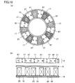
- the rotor (the shroud 12 of the impeller 10) includes a permanent magnet 17A magnetized in the direction of the rotation axis, a permanent magnet 67A magnetized in the circumferential direction, and a magnetic body 70A. It is out.
- the permanent magnet 17A is arranged so that the magnetic poles of adjacent magnets have different orientations, and the permanent magnet 67A is arranged so that the same magnetic pole as the permanent magnet 17A approaches the end face of the permanent magnet 17A on the partition wall 6 side.
- the number of permanent magnets 17A and the number of permanent magnets 67A is the same.
- the magnetizing direction length of the permanent magnet 67A is shorter than the width of the permanent magnet 17A, and if the center of the magnetizing direction length of the permanent magnet 67A is made coincident with the boundary between adjacent magnets of the permanent magnet 17A, a gap is formed in the circumferential direction.
- the magnetic body 70A is disposed in the gap. In this case, the magnetic flux is focused on the magnetic body 70A, and a stronger field magnetic flux can be obtained and the torque can be increased compared to the case where there is no magnetic body or the configuration of the normal Halbach arrangement (FIG. 10). Furthermore, in the arrangement of FIG. 11, it is possible to suppress a decrease in the permeance coefficient of the permanent magnets 17A and 67A.
- FIG. 12 shows that the magnetic body 72 is disposed on the end surface of the permanent magnet 17A opposite to the partition wall 6 in the configuration of FIG. Magnetic flux can be further strengthened by the effect of the magnetic body 72.
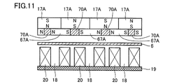
- FIG. 13 shows another magnet arrangement.
- the rotor is composed of a permanent magnet 17B magnetized in the rotation axis direction, a permanent magnet 67B magnetized in the circumferential direction, and a magnetic body 70B.
- the permanent magnets 17B are arranged with a gap in the direction of the magnetic poles of the adjacent magnets, and the permanent magnet 67B is arranged to protrude toward the partition wall 6 in the gap.
- this configuration allows the permeance coefficient to be larger than that in FIG. 11 because the flatness of the permanent magnet 17B is reduced.
- the number of permanent magnets 17B and the number of permanent magnets 67B is the same.
- the permanent magnet 67B is magnetized in the circumferential direction (rotation direction of the rotor).
- the plurality of permanent magnets 17B and the plurality of permanent magnets 67B are alternately arranged in a Halbach array structure along the same circle at equal angular intervals one by one.
- the permanent magnet 17B with the N pole facing the partition wall 6 and the permanent magnet 17B with the S pole facing the partition wall 6 are alternately arranged along the same circle with gaps provided at equal angular intervals.
- the N pole of each permanent magnet 67B is disposed toward the permanent magnet 17B with the N pole directed toward the partition wall 6, and the S pole of each permanent magnet 67B is disposed toward the permanent magnet 17B with the S pole directed toward the partition wall 6. Is done.
- the shapes of the plurality of permanent magnets 17B are the same, and the shapes of the plurality of permanent magnets 67B are the same.
- the axial length of the permanent magnet 17B is shorter than the width of the permanent magnet 67B.
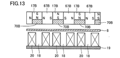
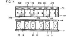
- the magnetic body 72 is arranged on the end surface of the permanent magnet 17 ⁇ / b> B opposite to the partition wall 6 in the configuration of FIG. 13. Magnetic flux can be further strengthened by the effect of the magnetic body 72.
- the plurality of permanent magnets 17 embedded in the shroud 12 may be arranged without providing gaps along the same circle at equal angular intervals so that adjacent magnetic poles are different from each other.
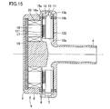
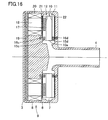
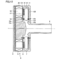
- FIG. 15 to 17 are cross-sectional views showing the main parts of the first to third modified examples of the pump unit 1 in which the arrangement of the ring magnets and the position where the dynamic pressure grooves are provided are changed.
- the dynamic pressure groove 121 may be provided on the surface of the shroud 12 of the impeller 10.
- the dynamic pressure groove 122 may be provided on the surface of the shroud 11 of the impeller 10.
- the ring-shaped permanent magnets 15c provided on the inner peripheral side of the impeller 10 are provided. 15d may be provided, and the ring-shaped permanent magnets 16c and 16d facing the ring-shaped permanent magnets 15c and 15d may be provided on the walls of the partition wall 6 and the pump chamber 7 instead of the ring-shaped permanent magnets 16a and 16b.
- Other configurations in FIG. 16 are the same as those in FIG. 3, and thus description thereof will not be repeated.
- the dynamic pressure groove 121 may be provided on the surface of the shroud 12 of the impeller 10.
- the dynamic pressure groove 122 may be provided on the surface of the shroud 11 of the impeller 10.
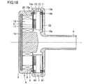
- FIG. 18 is a cross-sectional view illustrating a main part of a fourth modification of the pump unit 1 in which the arrangement of the ring-shaped magnets and the position where the dynamic pressure grooves are provided are changed.
- dynamic pressure grooves 61 and 62 are formed on the outer peripheral surface of the shroud in addition to the configuration of FIG. 3.
- Other configurations in FIG. 18 are the same as those in FIG.
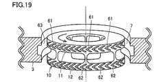
- FIG. 19 is a view showing a first example of a dynamic pressure groove formed on the outer peripheral surface of the shroud.
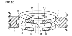
- FIG. 20 is a diagram illustrating a second example of the dynamic pressure grooves formed on the outer peripheral surface of the shroud.
- the dynamic pressure grooves 61 and 62 are formed on the outer peripheral surfaces of the shrouds 11 and 12, respectively.
- the tips of the dynamic pressure grooves 61 and 62 are directed in the direction opposite to the rotation direction of the impeller 10.
- the impeller 10 rotates in the direction of the arrow, the liquid pressure increases toward the tip portions of the dynamic pressure grooves 61 and 62. For this reason, a repulsive force is generated between the impeller 10 and the inner peripheral surface of the pump chamber 7, and this becomes a dynamic pressure.
- dynamic pressure grooves 64 and 65 are formed on the outer peripheral surfaces of the shrouds 11 and 12, respectively.
- the depth of each of the dynamic pressure grooves 64 and 65 is gradually shallower in the direction opposite to the rotation direction of the impeller 10.
- the pressure of the liquid increases toward the tips of the dynamic pressure grooves 64 and 65. For this reason, a repulsive force is generated between the impeller 10 and the inner peripheral surface of the pump chamber 7, and this becomes a dynamic pressure.
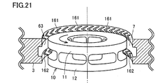
- dynamic pressure grooves may be provided on the wall surface of the pump chamber 7 facing the shrouds 11 and 12 instead of being provided on the outer peripheral surfaces of the shrouds 11 and 12.
- FIG. 21 is a view showing a first example of a dynamic pressure groove formed on the wall surface of the pump chamber.
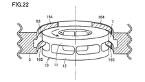
- FIG. 22 is a diagram illustrating a second example of the dynamic pressure grooves formed on the wall surface of the pump chamber.
- dynamic pressure grooves 161 and 162 similar in shape to the dynamic pressure grooves 61 and 62 shown in FIG. 19 are formed on the wall surface of the pump chamber 7 facing the outer peripheral surfaces of the shrouds 11 and 12.
- dynamic pressure grooves 164 and 165 having the same shape as the dynamic pressure grooves 64 and 65 shown in FIG. 20 are formed on the wall surface of the pump chamber 7 facing the outer peripheral surfaces of the shrouds 11 and 12.
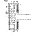
- 23 to 25 are cross-sectional views respectively showing main parts of fifth to seventh modified examples of the pump unit 1 in which the arrangement of the ring magnets and the position where the dynamic pressure grooves are provided are changed.
- FIG. 23 has dynamic pressure grooves 261 and 262 formed in place of the dynamic pressure grooves 61 and 62 in the configuration shown in FIG.
- the configuration of other parts in FIG. 23 is the same as that in FIG.
- the dynamic pressure grooves 261 and 262 instead of providing the dynamic pressure grooves 61 and 62 on the outer peripheral surface of the shroud 11 and 12 of the impeller, the dynamic pressure grooves 261 and 262 are provided on the inner peripheral surface of the shroud 11 and 12 of the impeller 10. Also good.
- the ring-shaped permanent magnets 15c, 15d, 16c, and 16d are arranged in place of the ring-shaped permanent magnets 15a, 15b, 16a, and 16b in the configuration shown in FIG.
- the configuration of other parts in FIG. 24 is the same as that in FIG.
- the position where the ring-shaped magnet is arranged may be changed to the inner peripheral side of the shroud 11, 12 of the impeller 10 instead of being provided on the outer peripheral side of the shroud 11, 12 of the impeller 10.
- the dynamic pressure grooves 261 and 262 are formed instead of the dynamic pressure grooves 61 and 62 in the configuration shown in FIG.
- the configuration of other parts in FIG. 25 is the same as that in FIG.
- the dynamic pressure grooves 261 and 262 instead of providing the dynamic pressure grooves 61 and 62 on the outer peripheral surface of the shroud 11 and 12 of the impeller, the dynamic pressure grooves 261 and 262 are provided on the inner peripheral surface of the shroud 11 and 12 of the impeller 10. Also good.
- the dynamic pressure groove may be provided on the impeller 10 or on the wall surface of the pump chamber 7. Further, it may be either whether the ring-shaped magnet is provided on the outer peripheral side of the impeller or on the outer peripheral side. The combination of the position of the dynamic pressure groove and the position of the ring-shaped magnet may be applied to the pump unit 1 even for a combination not shown.
- the attractive force of the drive unit and the negative stiffness component in the axial direction of the attractive force of the ring-shaped magnet for offsetting it cause instability of the impeller behavior.
- the ring-shaped permanent magnet is arranged to cancel out the attractive force from the drive unit.
- the coil of the drive unit has a coreless structure so that the axial attractive force from the drive unit does not work, and the ring-shaped permanent magnet has a dedicated arrangement that strengthens the support force in the radial direction.
- the impeller can be stably levitated and rotated.
- the cogging torque of the motor is reduced, the impeller can be started and rotated smoothly, and the restoring force in the radial direction is also increased, thereby improving the disturbance resistance of the impeller.
- the centrifugal pump device of the present embodiment includes a housing 2, an impeller 10, a drive unit 9, a plurality of first permanent magnets 17, and ring-shaped second to fifth permanent magnets 15a to 15d, 16a. To 16d.
- the housing 2 includes a pump chamber 7 and a motor chamber 8 partitioned by a partition wall 6.
- the impeller 10 is rotatably provided with the axis intersecting the partition wall 6 in the pump chamber 7 as a rotation axis, and sends liquid by centrifugal force during rotation.
- the driving unit 9 is provided in the motor chamber 8 and rotates the impeller 10 through the partition wall 6.
- the plurality of first permanent magnets 17 are provided on one surface of the impeller 10 along the partition wall 6 and are disposed along the same circle.
- the drive unit 9 includes a plurality of air-core coils 20 that are provided to face the plurality of first permanent magnets 17 and generate a rotating magnetic field.
- First dynamic pressure grooves 22 and 122 are formed on the other surface opposite to the one surface of the impeller 10 or the inner wall of the pump chamber 7 facing the other surface.
- Second dynamic pressure grooves 21 and 121 are formed on one surface of the impeller 10 or the partition wall 6 facing the one surface.
- the ring-shaped second permanent magnet 15 a is disposed on one surface of the impeller 10.
- the ring-shaped third permanent magnet 15 b is disposed on the other surface of the impeller 10.
- the ring-shaped fourth permanent magnet 16a is provided on the partition wall 6 and faces the second permanent magnet 15a.
- the ring-shaped fifth permanent magnet 16b is provided on the inner wall of the pump chamber 7 and faces the third permanent magnet 15b.
- the second permanent magnet 15a and the fourth permanent magnet 16a are arranged so that the magnetic poles of the opposing surfaces are different (one is an N pole and the other is an S pole).
- the 3rd permanent magnet 15b and the 5th permanent magnet 16b are arrange
- the drive unit 9 further includes a magnetic body 19 that is disposed on the side opposite to the partition wall 6 of the plurality of air-core coils 20 and is magnetically coupled to the plurality of air-core coils 20.
- the second and third permanent magnets 15 a and 15 b are provided on the outer peripheral portions of one surface and the other surface of the impeller 10, respectively.
- the fourth permanent magnet 16 a is provided on the outer peripheral portion of the partition wall 6, and the fifth permanent magnet 16 b is provided on the outer peripheral portion of the inner wall of the pump chamber 7.
- the second and third permanent magnets 15 c and 15 c are provided on the inner peripheral portions of one surface and the other surface of the impeller 10, respectively.
- the fourth permanent magnet 16 c is provided on the inner peripheral portion of the partition wall 6, and the fifth permanent magnet 16 d is provided on the inner peripheral portion of the inner wall of the pump chamber 7.
- the third dynamic pressure grooves 61, 62, 161 are formed on the outer peripheral surface of the impeller 10 or the outer peripheral surface of the pump chamber 7 facing the impeller 10, or the inner peripheral surface of the impeller 10 or the inner peripheral surface of the pump chamber 7 facing the impeller 10. 162, 261, and 262 are formed.
- the plurality of first permanent magnets 17 are arranged along the same circle so that adjacent magnetic poles are different from each other.
Landscapes
- Engineering & Computer Science (AREA)
- Mechanical Engineering (AREA)
- General Engineering & Computer Science (AREA)
- Power Engineering (AREA)
- Physics & Mathematics (AREA)
- Fluid Mechanics (AREA)
- Electromagnetism (AREA)
- Structures Of Non-Positive Displacement Pumps (AREA)
- Connection Of Motors, Electrical Generators, Mechanical Devices, And The Like (AREA)
- Permanent Magnet Type Synchronous Machine (AREA)
Applications Claiming Priority (2)
| Application Number | Priority Date | Filing Date | Title |
|---|---|---|---|
| JP2015068605A JP6452518B2 (ja) | 2015-03-30 | 2015-03-30 | 遠心式ポンプ装置 |
| JP2015-068605 | 2015-03-30 |
Publications (1)
| Publication Number | Publication Date |
|---|---|
| WO2016158162A1 true WO2016158162A1 (ja) | 2016-10-06 |
Family
ID=57007081
Family Applications (1)
| Application Number | Title | Priority Date | Filing Date |
|---|---|---|---|
| PCT/JP2016/056219 Ceased WO2016158162A1 (ja) | 2015-03-30 | 2016-03-01 | 遠心式ポンプ装置 |
Country Status (2)
| Country | Link |
|---|---|
| JP (1) | JP6452518B2 (OSRAM) |
| WO (1) | WO2016158162A1 (OSRAM) |
Families Citing this family (1)
| Publication number | Priority date | Publication date | Assignee | Title |
|---|---|---|---|---|
| CN112392738A (zh) * | 2020-11-27 | 2021-02-23 | 浙江鸿吉智能控制有限公司 | 一种新式非接触式电磁驱动泵 |
Citations (3)
| Publication number | Priority date | Publication date | Assignee | Title |
|---|---|---|---|---|
| JP2008132131A (ja) * | 2006-11-28 | 2008-06-12 | Terumo Corp | センサレス磁気軸受型血液ポンプ装置 |
| JP2010261394A (ja) * | 2009-05-08 | 2010-11-18 | Ntn Corp | 遠心式ポンプ装置 |
| WO2013108681A1 (ja) * | 2012-01-18 | 2013-07-25 | テルモ株式会社 | 遠心式ポンプ装置 |
-
2015
- 2015-03-30 JP JP2015068605A patent/JP6452518B2/ja not_active Expired - Fee Related
-
2016
- 2016-03-01 WO PCT/JP2016/056219 patent/WO2016158162A1/ja not_active Ceased
Patent Citations (3)
| Publication number | Priority date | Publication date | Assignee | Title |
|---|---|---|---|---|
| JP2008132131A (ja) * | 2006-11-28 | 2008-06-12 | Terumo Corp | センサレス磁気軸受型血液ポンプ装置 |
| JP2010261394A (ja) * | 2009-05-08 | 2010-11-18 | Ntn Corp | 遠心式ポンプ装置 |
| WO2013108681A1 (ja) * | 2012-01-18 | 2013-07-25 | テルモ株式会社 | 遠心式ポンプ装置 |
Also Published As
| Publication number | Publication date |
|---|---|
| JP2016188592A (ja) | 2016-11-04 |
| JP6452518B2 (ja) | 2019-01-16 |
Similar Documents
| Publication | Publication Date | Title |
|---|---|---|
| JP5577506B2 (ja) | 遠心式ポンプ装置 | |
| JP5656835B2 (ja) | 回転駆動装置およびそれを用いた遠心式ポンプ装置 | |
| JP5681403B2 (ja) | 遠心式ポンプ装置 | |
| US9366261B2 (en) | Centrifugal pump device | |
| JP5443197B2 (ja) | 遠心式ポンプ装置 | |
| CN102341600B (zh) | 离心式泵装置 | |
| JP5378010B2 (ja) | 遠心式ポンプ装置 | |
| JP5969979B2 (ja) | 回転駆動装置およびそれを用いた遠心式ポンプ装置 | |
| JP5378012B2 (ja) | 遠心式ポンプ装置 | |
| WO2016158173A1 (ja) | 遠心式ポンプ装置 | |
| JP6452518B2 (ja) | 遠心式ポンプ装置 | |
| JP2016188593A (ja) | 遠心式ポンプ装置 | |
| JP6698278B2 (ja) | 遠心式ポンプ装置 | |
| JP5693812B2 (ja) | 遠心式ポンプ装置 | |
| JP2016188591A (ja) | 遠心式ポンプ装置 | |
| JP5378060B2 (ja) | 遠心式ポンプ装置 | |
| WO2016158172A1 (ja) | 遠心式ポンプ装置 | |
| WO2016158185A1 (ja) | 遠心式ポンプ装置 | |
| JP2012013043A (ja) | 回転駆動装置およびそれを用いた遠心式ポンプ装置 |
Legal Events
| Date | Code | Title | Description |
|---|---|---|---|
| 121 | Ep: the epo has been informed by wipo that ep was designated in this application |
Ref document number: 16772046 Country of ref document: EP Kind code of ref document: A1 |
|
| NENP | Non-entry into the national phase |
Ref country code: DE |
|
| 122 | Ep: pct application non-entry in european phase |
Ref document number: 16772046 Country of ref document: EP Kind code of ref document: A1 |