WO2016158152A1 - 液冷式圧縮機 - Google Patents
液冷式圧縮機 Download PDFInfo
- Publication number
- WO2016158152A1 WO2016158152A1 PCT/JP2016/056084 JP2016056084W WO2016158152A1 WO 2016158152 A1 WO2016158152 A1 WO 2016158152A1 JP 2016056084 W JP2016056084 W JP 2016056084W WO 2016158152 A1 WO2016158152 A1 WO 2016158152A1
- Authority
- WO
- WIPO (PCT)
- Prior art keywords
- gas
- compressor
- liquid
- flow path
- oil
- Prior art date
- Legal status (The legal status is an assumption and is not a legal conclusion. Google has not performed a legal analysis and makes no representation as to the accuracy of the status listed.)
- Ceased
Links
Images









Classifications
-
- F—MECHANICAL ENGINEERING; LIGHTING; HEATING; WEAPONS; BLASTING
- F04—POSITIVE - DISPLACEMENT MACHINES FOR LIQUIDS; PUMPS FOR LIQUIDS OR ELASTIC FLUIDS
- F04B—POSITIVE-DISPLACEMENT MACHINES FOR LIQUIDS; PUMPS
- F04B39/00—Component parts, details, or accessories, of pumps or pumping systems specially adapted for elastic fluids, not otherwise provided for in, or of interest apart from, groups F04B25/00 - F04B37/00
-
- F—MECHANICAL ENGINEERING; LIGHTING; HEATING; WEAPONS; BLASTING
- F04—POSITIVE - DISPLACEMENT MACHINES FOR LIQUIDS; PUMPS FOR LIQUIDS OR ELASTIC FLUIDS
- F04B—POSITIVE-DISPLACEMENT MACHINES FOR LIQUIDS; PUMPS
- F04B39/00—Component parts, details, or accessories, of pumps or pumping systems specially adapted for elastic fluids, not otherwise provided for in, or of interest apart from, groups F04B25/00 - F04B37/00
- F04B39/06—Cooling; Heating; Prevention of freezing
-
- F—MECHANICAL ENGINEERING; LIGHTING; HEATING; WEAPONS; BLASTING
- F04—POSITIVE - DISPLACEMENT MACHINES FOR LIQUIDS; PUMPS FOR LIQUIDS OR ELASTIC FLUIDS
- F04C—ROTARY-PISTON, OR OSCILLATING-PISTON, POSITIVE-DISPLACEMENT MACHINES FOR LIQUIDS; ROTARY-PISTON, OR OSCILLATING-PISTON, POSITIVE-DISPLACEMENT PUMPS
- F04C18/00—Rotary-piston pumps specially adapted for elastic fluids
- F04C18/08—Rotary-piston pumps specially adapted for elastic fluids of intermeshing-engagement type, i.e. with engagement of co-operating members similar to that of toothed gearing
- F04C18/12—Rotary-piston pumps specially adapted for elastic fluids of intermeshing-engagement type, i.e. with engagement of co-operating members similar to that of toothed gearing of other than internal-axis type
- F04C18/14—Rotary-piston pumps specially adapted for elastic fluids of intermeshing-engagement type, i.e. with engagement of co-operating members similar to that of toothed gearing of other than internal-axis type with toothed rotary pistons
- F04C18/16—Rotary-piston pumps specially adapted for elastic fluids of intermeshing-engagement type, i.e. with engagement of co-operating members similar to that of toothed gearing of other than internal-axis type with toothed rotary pistons with helical teeth, e.g. chevron-shaped, screw type
-
- F—MECHANICAL ENGINEERING; LIGHTING; HEATING; WEAPONS; BLASTING
- F04—POSITIVE - DISPLACEMENT MACHINES FOR LIQUIDS; PUMPS FOR LIQUIDS OR ELASTIC FLUIDS
- F04C—ROTARY-PISTON, OR OSCILLATING-PISTON, POSITIVE-DISPLACEMENT MACHINES FOR LIQUIDS; ROTARY-PISTON, OR OSCILLATING-PISTON, POSITIVE-DISPLACEMENT PUMPS
- F04C29/00—Component parts, details or accessories of pumps or pumping installations, not provided for in groups F04C18/00 - F04C28/00
- F04C29/04—Heating; Cooling; Heat insulation
-
- F—MECHANICAL ENGINEERING; LIGHTING; HEATING; WEAPONS; BLASTING
- F04—POSITIVE - DISPLACEMENT MACHINES FOR LIQUIDS; PUMPS FOR LIQUIDS OR ELASTIC FLUIDS
- F04C—ROTARY-PISTON, OR OSCILLATING-PISTON, POSITIVE-DISPLACEMENT MACHINES FOR LIQUIDS; ROTARY-PISTON, OR OSCILLATING-PISTON, POSITIVE-DISPLACEMENT PUMPS
- F04C29/00—Component parts, details or accessories of pumps or pumping installations, not provided for in groups F04C18/00 - F04C28/00
- F04C29/06—Silencing
Definitions
- the present invention relates to a liquid cooled compressor.
- a coolant is supplied to cool the inside of the compressor body.
- oil-cooled screw compressor using oil as a coolant, the following cooling is performed.
- the oil-cooled screw compressor includes a pair of male and female screw rotors engaged with each other in a rotor casing, and the screw rotors are rotatably supported by bearings on the suction side and the discharge side.
- Refueling holes are respectively provided in a rotor chamber, a bearing portion and the like which are gas compression spaces in the screw compressor.
- the oil supplied to the rotor chamber through the feed holes serves to cool the screw rotors and to seal and lubricate between the screw rotors and between the screw rotors and the inner wall of the rotor casing.
- Patent Document 1 As a vibration and noise countermeasure technology according to the prior art in a compressor, for example, Patent Document 1 is known.
- Patent Document 1 mixes pressure gas separated by an oil separator with working fluid oil flowing in an oil injection pipe through a gas pipe to make the working fluid oil compressible, thereby causing pressure pulsation inside the oil injection pipe.
- a screw compressor that absorbs
- gas piping is additionally provided, and a throttling valve and a throttling valve are provided in each of the gas piping and the oil injection piping, and a certain amount of gas is mixed in the working fluid oil. , Throttle valve and throttle stop valve are adjusted.
- the technology disclosed in Patent Document 1 is very complicated because the control of the throttling valve and the throttling valve is performed by providing the gas pipe, the throttling valve, and the throttling valve. ing.
- the technical problem to be solved by the present invention is to reduce vibration of piping and noise from an apparatus connected to the piping by a simple configuration in a liquid-cooled compressor.
- the following liquid-cooled compressor is provided.
- the liquid-cooled compressor comprises a compressor body for compressing a gas, and a liquid supply flow path communicating with a liquid supply hole for supplying a coolant into the gas compression space formed in the compressor body. And a gas buffer unit having a gas storage unit for storing a gas that receives the pressure of the cooling fluid flowing through the liquid supply flow passage.
- the pressure of the cooling fluid flowing through the liquid supply flow path fluctuates and pulsation occurs
- the pressure of the pulsation is received by the gas stored in the gas storage portion of the gas buffer portion, and the gas is compressed. Pulsation can be absorbed and attenuated by action. As a result, the vibration of the pipe and the noise from the device connected to the pipe can be reduced by the simple configuration.
- the present invention can have the following features in addition to the features described above.
- the gas buffer portion is provided in at least one of the compressor body and the liquid supply flow path close to the compressor body. According to the said structure, since the gas buffer part is provided near the generation source of pulsation, the vibration and noise by pulsation can be suppressed more effectively.
- the gas buffer portion is a tubular body branched at a branching portion from the liquid supply flow path close to the compressor body, and the distal end portion of the tubular body is closed. According to the said structure, since existing piping can be utilized as a gas buffer part, a gas buffer part can be comprised simply and at low cost.
- the gas buffer portion is a space branched from the liquid supply flow path of the compressor body at a branching portion, and is a space provided in the compressor body, and the end of the space is closed. According to the said structure, since a compressor main body can be utilized as a gas buffer part, a gas buffer part can be comprised simply and at low cost.
- the gas buffer portion is branched from the liquid supply flow path at a branch portion. According to the said structure, since a liquid supply flow path can be utilized as a gas buffer part, a gas buffer part can be comprised simply and at low cost.
- the gas storage portion of the gas buffer portion is located above the liquid supply flow path where the branch portion is located. According to the structure, the gas contained in the cooling fluid flowing through the liquid supply flow path is retained in the gas storage portion, so that the gas buffer portion can operate stably.
- An opening communicating with the gas storage portion of the gas buffer portion is disposed at a position facing the flow direction of the coolant. According to the structure, the gas contained in the cooling fluid flowing through the liquid supply flow path easily flows into the gas buffer portion, so the retention of the gas in the gas storage portion becomes easy, and the gas buffer portion operates stably. can do.
- the compressor body incorporates a pair of male and female screw rotors engaged with each other. According to the said structure, the screw compressor by which the vibration and noise resulting from the pulsation in a liquid supply flow path were suppressed is provided.
- FIG. 1st Embodiment of this invention The figure which shows schematic structure of the liquid cooling type compressor which concerns on 1st Embodiment of this invention.
- the figure which shows schematic structure of the liquid cooling type compressor which concerns on 6th Embodiment of this invention The figure which shows the 1st example of the principal part of the liquid cooling compressor of this invention.
- the typical perspective view of the principal part shown in FIG. The figure which shows the 2nd example of the principal part of the liquid cooling compressor of this invention.
- the typical perspective view of the principal part shown in FIG. The figure which shows the 3rd example of the principal part of the liquid cooling compressor of this invention.
- the figure which shows the 4th example of the principal part of the liquid cooling compressor of this invention The figure which shows the 5th example of the principal part of the liquid cooling compressor of this invention.
- the figure which shows the 6th example of the principal part of the liquid cooling compressor of this invention The figure which shows the 7th example of the principal part of the liquid cooling compressor of this invention.
- the typical perspective view of the principal part shown in FIG. The figure which shows the 3rd example of the principal part of the liquid cooling compressor of this invention.
- the figure which shows the 9th example of the principal part of the liquid cooling compressor of this invention The figure which shows the 10th example of the principal part of the liquid cooling compressor of this invention.
- the figure which shows the 11th example of the principal part of the liquid cooling compressor of this invention The figure which shows the 12th example of the principal part of the liquid cooling compressor of this invention.
- the figure which shows the 13th example of the principal part of the liquid cooling compressor of this invention The figure which shows the 14th example of the principal part of the liquid cooling compressor of this invention.
- the schematic diagram which shows the 15th example of the principal part of the liquid cooling compressor of this invention The schematic diagram which shows the 16th example of the principal part of the liquid cooling compressor of this invention.
- the schematic diagram which shows the 17th example of the principal part of the liquid cooling compressor of this invention The figure which shows the 10th example of the principal part of the liquid cooling compressor of this invention.
- the figure which shows the 11th example of the principal part of the liquid cooling compressor of this invention The figure which shows the 12th example of the principal part of the liquid cooling
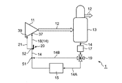
- FIG. 1 shows a schematic configuration of a liquid-cooled compressor 1.
- the liquid-cooled compressor 1 includes, for example, a compressor body 11, an oil separation and recovery device 13, an oil filter 17, an oil cooler 15, and a temperature control valve 19, as shown in FIG.
- the liquid-cooled compressor 1 uses oil as a coolant and compresses a gas (for example, air) to be compressed with a pair of male and female screw rotors 34 that intermesh with each other. It is a cold screw compressor.
- a pair of male and female screw rotors 34 engaging with each other is accommodated in a rotor chamber (gas compression space) 33 formed in a rotor casing 32 of the compressor main body 11.
- an oil separation and recovery device 13 is provided in the discharge flow passage 12 extending from the compressor body 11.
- compressed gas is discharged from the compressor body 11 with oil and separated into compressed gas and oil by the oil separation and recovery device 13.
- the compressed gas flows from the portion of the discharge flow passage 12 connected to the upper portion of the oil separation and recovery unit 13 toward the demand facility.
- the oil separated by the oil separation and recovery device 13 is temporarily stored in an oil reservoir formed at the lower part of the oil separation and recovery device 13.
- a main oil supply flow path (liquid supply flow path) 14 is formed in which the oil separated by the oil separation and recovery unit 13 flows from the oil separation and recovery unit 13 to the gas compression space of the compressor body 11. ing.
- An oil filter 17 and a temperature control valve 19 are sequentially provided on the downstream side of the oil separation and recovery device 13 in the main oil supply flow path 14 (hereinafter simply referred to as the main flow path 14).
- the main flow passage 14 is branched into the cooling branch flow passage 14A and the bypass flow passage 14B in the temperature control valve 19, and the cooling branch flow passage 14A and the bypass flow passage 14B join at the cooling joining point 51.
- An oil cooler 15 is disposed on the cooling branch flow channel 14A.
- the temperature control valve 19 causes the oil to flow through the cooling branch channel 14A when the oil temperature is high, and the oil to flow through the bypass channel 14B when the oil temperature is low.
- a refueling branch point 52 is provided in the main flow path 14.
- a bearing oil supply flow path 21 communicating with the bearing and shaft seal portion in the compressor body 11 is branched from the main flow path 14.
- the rotor chamber (gas compression space) 33 is provided through the main body oil supply hole 37 communicating with the main body oil supply flow path (liquid supply flow path) 18 which is the main flow path 14 downstream from the branch point.
- the bearing / shaft seal portion is refueled through the bearing refueling hole 39 of the bearing refueling flow passage 21.
- the oil from the main oil supply channel 18 is used for cooling of the compressed gas, sealing between the screw rotors 34 and lubrication.
- the oil from the bearing oil supply channel 21 is used to lubricate and seal the bearing / shaft seal.
- the gas buffer unit 20 is provided in the middle of the main flow path 14.
- the gas buffer unit 20 includes a damper main body 24 which is a tubular body which is branched from the main flow path (liquid supply flow path) 14 by a T-shaped branch which is a branch portion 22 and is connected to the branch portion 22. .
- the end of the damper body 24 is closed by a cap 26.
- the pipe joint which is the branch portion 22 has an inlet 23, an outlet 25 and a branch connection port 27.
- the upstream side piping of the main flow passage 14 is connected to the inlet 23, the downstream side piping of the main flow passage 14 is connected to the outlet 25, and the damper main body 24 is connected to the branch connection port 27.
- a gas storage portion 28 for storing gas is formed in the internal space of the damper main body 24, a gas storage portion 28 for storing gas is formed.
- the pressure of the oil flowing through the main flow channel 14 fluctuates and pulsation occurs, the pressure of the pulsation is received by the gas stored in the gas storage unit 28 of the gas buffer unit 20, and the pulsation is absorbed by the compression action of the gas. It can be attenuated.
- the oil flows along the main flow path 14 extending from the lower side to the upper side and then to the right side.
- the gas storage portion 28 of the gas buffer portion 20 is located above the main flow path 14 where the branch portion 22 is located. Since the gas contained in the oil flowing through the main flow passage 14 is retained in the gas storage unit 28, the gas buffer unit 20 can operate stably. Further, the opening of the tubular body communicating with the gas storage portion 28 connected to the branch connection port 27 is disposed at a position facing the flow direction of the oil. Since the gas contained in the oil flowing through the main flow path 14 easily flows into the gas storage portion 28 of the damper main body 24, the retention of the gas in the gas storage portion 28 becomes easy, and the gas buffer portion 20 operates stably. be able to. As a result, vibration and noise due to pulsation can be suppressed by the gas accumulated in the gas storage unit 28.
- the inner diameter of the damper main body 24 which is a tubular body may be the same as or different from the inner diameter of the main flow path 14.
- the inside diameter of the damper main body 24 can be, for example, in the range of 0.5 times to 2.0 times the inside diameter of the piping of the main flow passage 14, but is limited to the numerical value Not.
- the gas accumulated in the gas storage portion 28 of the damper main body 24 is not easily degassed unless the cap 26 is loosened to positively degas the gas. Therefore, if the gas storage portion 28 is filled with gas before the operation of the liquid-cooled compressor 1, it is necessary to wait for the gas to be received by being supplied from the gas contained in the oil flowing through the main flow path 14. There is no.
- a gas buffer portion 20 is provided in the main flow path 14 close to the compressor main body 11, that is, at a midway position of the main body oil supply flow path 18 located between the main body oil supply hole 37 and the oil supply branch point 52.
- the gas buffer unit 20 is provided near the main body oil supply hole 37 of the compressor main body 11 which is a generation source of pulsation, vibration and noise due to pulsation can be more effectively suppressed. it can.
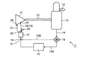
- FIG. 2 shows a liquid-cooled compressor 1 according to a second embodiment of the present invention
- the same reference numerals as in FIG. 1 denote the same parts as in the liquid-cooled compressor 1 according to the first embodiment. Description is omitted. The same applies to the third to sixth embodiments.
- the gas buffer unit 20 is provided at the refueling branch point 52 of the main flow passage 14.
- the main flow path 14 is branched into the main body oil supply channel 18 and the bearing oil supply channel 21.
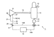
- the oil filter 17 is provided between the cooling junction point 51 and the oil supply branch point 52.
- the second embodiment and the third embodiment are compared, only the arrangement position of the oil filter 17 is different, and there is no difference in the other configurations.
- the liquid-cooled compressor 1 according to the third embodiment is also capable of suppressing vibration and noise due to pulsation and changing the configuration at a minimum. Become.
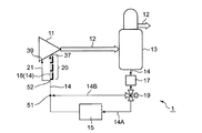
- the gas buffer unit 20 is provided at the cooling junction point 51 of the main flow passage 14.
- the gas buffer portion 20 is provided at the cooling junction point 51 which is the downstream end of the aggregated part, thereby suppressing vibration and noise due to pulsation. And configuration changes with minimal effort.
- a plurality of gas buffer sections 20 are provided in series at a midway position of the main oil supply passage 18 of the main passage 14. According to the said structure, the suppression effect of the vibration and noise by pulsation can be enlarged more.
- the gas buffer unit 20 of the second to fourteenth examples shown in FIGS. 9 to 22 can be used.
- a cross-shaped pipe joint can be appropriately used as the branch portion 22 instead of the T-shaped pipe joint.
- the gas buffer portion 20 of the second example is branched from the main flow path (liquid supply flow path) 14 by a T-shaped pipe joint which is a branch portion 22.
- the inlet 23 and the outlet 25 of the branch portion 22 are connected in the middle of the main flow path 14.
- An elbow pipe joint 45 which is a tubular body leading to the gas storage portion 28 is connected to the branch connection port 27 of the branch portion 22.
- the damper main body 24 is connected to the connection port 47 of the elbow pipe joint 45. That is, the damper main body 24 is connected to the branch portion 22 via the elbow pipe joint 45.
- the gas storage portion 28 of the gas buffer portion 20 is located above the main flow path 14 where the branch portion 22 is located.
- the oil flows along the main flow path 14 extending in the direction perpendicular to the paper surface after extending from the left to the right.
- the opening of the tubular body (elbow pipe joint 45) communicating with the gas storage portion 28 connected to the branch connection port 27 of the branch portion 22 is disposed at a position facing the flow direction of the oil. Since the gas contained in the oil flowing through the main flow path 14 easily flows into the gas storage portion 28 of the damper main body 24, the retention of the gas in the gas storage portion 28 becomes easy, and the gas buffer portion 20 operates stably. be able to. As a result, vibration and noise due to pulsation can be suppressed by the gas accumulated in the gas storage unit 28.
- the gas buffer portion 20 of the third example shown in FIG. 11 is branched from the main flow path (liquid supply flow path) 14 by a T-shaped pipe joint which is a branch portion 22.
- the damper main body 24 is connected to a branch connection port 27 located above the T-shaped branch portion 22.
- the gas storage portion 28 of the damper main body 24 is located above the main flow path 14 in which the branch portion 22 is located.
- the oil flows along the main flow path 14 extending from the left to the right. Since the gas contained in the oil flowing in the main flow passage 14 is retained in the gas storage portion 28, the gas buffer portion 20 can operate stably, and the gas retained in the gas storage portion 28 causes vibration or noise due to pulsation. Can be suppressed.
- the gas buffer unit 20 of the fourth example shown in FIG. 12 uses a branch unit 22 branched in three axial directions orthogonal to the X axis, Y axis, and Z axis.
- the gas storage portion 28 of the damper main body 24 is located above the main flow path 14 in which the branch portion 22 is located.
- the oil flows along the main flow path 14 extending from the left to the right and then in the direction perpendicular to the paper surface. Since the gas contained in the oil flowing in the main flow passage 14 is retained in the gas storage portion 28, the gas buffer portion 20 can operate stably, and the gas retained in the gas storage portion 28 causes vibration or noise due to pulsation. Can be suppressed.
- the gas buffer portion 20 of the fifth example shown in FIG. 13 is branched from the main flow path (liquid supply flow path) 14 by a Y-shaped pipe joint which is a branch portion 22.
- the damper main body 24 is connected to a branch connection port 27 located obliquely upward to the right of the Y-shaped branch portion 22.
- the gas storage portion 28 of the damper main body 24 is located above the main flow path 14 in which the branch portion 22 is located.
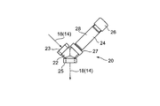
- the oil flows along the main flow path 14 which extends diagonally upward from the lower left. Since the gas contained in the oil flowing in the main flow passage 14 is retained in the gas storage portion 28, the gas buffer portion 20 can operate stably, and the gas retained in the gas storage portion 28 causes vibration or noise due to pulsation. Can be suppressed.
- the gas buffer portion 20 of the sixth example shown in FIG. 14 is branched from the main flow path (liquid supply flow path) 14 by a Y-shaped pipe joint which is a branch portion 22.
- the damper main body 24 is connected to a branch connection port 27 located obliquely upward to the right of the Y-shaped branch portion 22.
- the gas storage portion 28 of the damper main body 24 is located above the main flow path 14 in which the branch portion 22 is located.
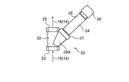
- the oil flows along the main flow path 14 extending obliquely from the upper left to the lower side. Since the gas contained in the oil flowing in the main flow passage 14 is retained in the gas storage portion 28, the gas buffer portion 20 can operate stably, and the gas retained in the gas storage portion 28 causes vibration or noise due to pulsation. Can be suppressed.
- the gas buffer portion 20 of the seventh example shown in FIG. 15 is a T-shaped pipe joint having a branch connection portion 29 extending obliquely downward to the right which is the branch portion 22 and branched from the main flow path (liquid supply flow path) 14 doing.
- a nipple pipe joint 40 is connected obliquely downward to the branch connection port 27 of the branch connection portion 29.
- An elbow pipe joint 45 is connected to the connection port 46 of the nipple pipe joint 40, and a damper main body 24 is connected to the connection port 47 of the elbow pipe joint 45.
- the inclination angles of the branch connection portion 29 and the nipple pipe joint 40 are configured such that the gas contained in the oil flowing through the main flow passage 14 can be introduced into the gas storage portion 28 of the damper main body 24.
- the inclination angle depends on the flow rate of the oil flowing through the main flow channel 14 but is, for example, an angle smaller than 20 degrees with respect to the main flow channel 14 extending in the substantially horizontal direction.
- the gas storage portion 28 of the damper main body 24 is located above the main flow path 14 where the branch portion 22 is located.
- the oil flows along the main flow path 14 extending from the left to the right. Since the gas contained in the oil flowing in the main flow passage 14 is retained in the gas storage portion 28, the gas buffer portion 20 can operate stably, and the gas retained in the gas storage portion 28 causes vibration or noise due to pulsation. Can be suppressed.
- the pipe length of the nipple pipe joint 40 is short. As the pipe length of the nipple pipe joint 40 is shorter, the gas contained in the oil flowing through the main flow passage 14 can be more easily introduced into the gas storage portion 28 of the damper main body 24. Since the gas contained in the oil flowing in the main flow path 14 is easily retained in the gas storage portion 28, the gas buffer portion 20 can operate stably, and the gas retained in the gas storage portion 28 causes vibration due to pulsation. And noise can be suppressed.
- the gas buffer portion 20 of the ninth example shown in FIG. 17 is a Y-shaped pipe joint having a branch connection portion 29A extending obliquely upward and rightward which is the branch portion 22 and branched from the main flow channel (liquid supply flow channel) 14 doing.
- the damper main body 24 is connected obliquely upward to the right with respect to the branch connection port 27 of the branch connection portion 29A.
- the gas storage portion 28 of the damper main body 24 is located above the main flow path 14 in which the branch portion 22 is located.
- the oil flows along the main flow path 14 extending downward from above. Since the gas contained in the oil flowing in the main flow passage 14 is retained in the gas storage portion 28, the gas buffer portion 20 can operate stably, and the gas retained in the gas storage portion 28 causes vibration or noise due to pulsation. Can be suppressed.
- the same one as the branch section 22 shown in FIG. 17 is used, but the oil flow direction is reverse to that shown in FIG.
- the oil flows along the main flow path 14 extending from the lower side to the upper side.
- the gas storage portion 28 of the damper main body 24 is located above the main flow path 14 in which the branch portion 22 is located. Since the gas contained in the oil flowing in the main flow passage 14 is retained in the gas storage portion 28, the gas buffer portion 20 can operate stably, and the gas retained in the gas storage portion 28 causes vibration or noise due to pulsation. Can be suppressed.
- the gas buffer portion 20 of the eleventh example shown in FIG. 19 is branched from the main flow path (liquid supply flow path) 14 by a T-shaped pipe joint which is a branch portion 22.
- the damper main body 24 is connected to the branch connection port 27 located above the pipe joint via the nipple pipe joint 40 and the elbow pipe joint 45. That is, the elbow pipe joint 45 bent at a right angle is connected to the connection port 46 of the nipple pipe joint 40, and the damper main body 24 is connected to the connection port 47 of the elbow pipe joint 45.
- the damper main body 24 is located above the branch portion 22 and extends in a substantially horizontal direction.
- the gas storage portion 28 of the damper main body 24 is located above the main flow path 14 in which the branch portion 22 is located.
- the oil flows along the main flow path 14 extending from the left to the right. Since the gas contained in the oil flowing in the main flow passage 14 is retained in the gas storage portion 28, the gas buffer portion 20 can operate stably, and the gas retained in the gas storage portion 28 causes vibration or noise due to pulsation. Can be suppressed.
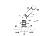
- the gas buffer unit 20 of the twelfth example shown in FIG. 20 has a configuration similar to that shown in FIG. 19, but differs in that elbow pipe fittings 45 having different bending angles are used.
- the bending angle is about 45 degrees, the bending angle can be any angle from 0 to 90 degrees.
- the damper main body 24 is positioned above the branch portion 22 and extends obliquely upward.
- the gas storage portion 28 of the damper main body 24 is located above the main flow path 14 in which the branch portion 22 is located.
- the oil flows along the main flow path 14 extending from the left to the right. Since the gas contained in the oil flowing in the main flow passage 14 is retained in the gas storage portion 28, the gas buffer portion 20 can operate stably, and the gas retained in the gas storage portion 28 causes vibration or noise due to pulsation. Can be suppressed.
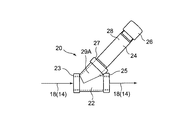
- the gas buffer portion 20 of the thirteenth example shown in FIG. 21 is a Y-shaped pipe joint having a branch connection portion 29A extending obliquely upward to the right which is the branch portion 22 and branched from the main flow channel (liquid supply flow channel) 14 doing.
- the damper main body 24 is connected obliquely upward to the right with respect to the branch connection port 27 of the branch connection portion 29A.
- the gas storage portion 28 of the damper main body 24 is located above the main flow path 14 in which the branch portion 22 is located.
- the oil flows along the main flow path 14 extending from the left to the right. Since the gas contained in the oil flowing in the main flow passage 14 is retained in the gas storage portion 28, the gas buffer portion 20 can operate stably, and the gas retained in the gas storage portion 28 causes vibration or noise due to pulsation. Can be suppressed.
- the gas buffer portion 20 of the fourteenth example shown in FIG. 22 is a Y-shaped pipe joint having a branch connection portion 29A extending obliquely upward to the left, which is the branch portion 22, and is branched from the main flow channel (liquid supply flow channel) 14 doing.
- the damper main body 24 is connected obliquely upward to the right with respect to the branch connection port 27 of the branch connection portion 29A.
- the gas storage portion 28 of the damper main body 24 is located above the main flow path 14 in which the branch portion 22 is located.
- the oil flows along the main flow path 14 extending from the left to the right. Since the gas contained in the oil flowing in the main flow passage 14 is retained in the gas storage portion 28, the gas buffer portion 20 can operate stably, and the gas retained in the gas storage portion 28 causes vibration or noise due to pulsation. Can be suppressed.
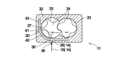
- the gas buffer unit 20 is provided inside the rotor casing 32 of the compressor body 11. Inside the rotor casing 32, an internal oil supply passage 35 which is a main passage (liquid supply passage) 14 is formed.
- the internal oil supply passage 35 is a passage that connects the oil supply connection hole 36 connected to the main body oil supply passage 18 and the main body oil supply hole 37.
- the internal oil supply flow passage 35 is formed such that the two main oil supply holes 37 communicate with one oil supply connection hole 36 provided on the lower side of the rotor casing 32. ing.
- the main body oil supply flow path 18 is connected to the internal oil supply flow path 35 via the oil supply connection hole 36, and the rotor chamber (gas compression space) 33 is supplied with oil through the main body oil supply hole 37.
- a damper space 41 branched from an internal branch point (branch portion) 38 provided in the middle of the internal oil supply flow path 35 is formed inside the rotor casing 32.
- the damper space 41 according to the sixth embodiment is a hollow formed inside the rotor casing 32 and works as a gas storage portion in the gas buffer portion 20.
- the damper space 41 of the fifteenth example shown in FIG. 23 has a curved portion 42 and a vertical straight portion 43, and although the lower end side is open at the internal branch point 38, the upper end side is closed.
- the curved portion 42 extends upward while communicating with the vertical straight portion 43 while curving from the inner branch point 38.
- the vertical straight portion 43 of the damper space 41 serving as the gas storage portion is located above the internal oil supply flow passage 35 in which the internal branch point 38 is located. Since the curved portion 42 is rounded, the gas contained in the oil flowing through the internal oil supply flow path 35 is easily guided to the damper space 41 and retained in the damper space 41, so the gas buffer portion 20 operates stably. can do. And the vibration and noise by pulsation can be suppressed by the gas which has stayed in the damper space 41.
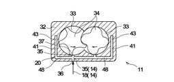
- the gas buffer unit 20 according to the sixteenth to twentieth examples illustrated in FIGS. 24 to 28 can be used.
- a plurality of damper spaces 41 having a horizontal straight 48 and a vertical straight portion 43 are used.
- the left and right lateral straights 48 extend in the lateral direction from the left and right internal branch points 38 and respectively communicate with the left and right vertical straight portions 43.
- the upper end sides of the left and right vertical straight portions 43 are respectively closed.
- the vertical straight portion 43 of the damper space 41 serving as the gas storage portion is located above the internal oil supply flow passage 35 in which the internal branch point 38 is located. Since the gas contained in the oil flowing through the internal oil supply flow passage 35 is retained in the left and right damper spaces 41, it can operate stably as the gas buffer portion 20, and the gas stagnated in the left and right damper spaces 41 causes pulsation. Vibration and noise due to
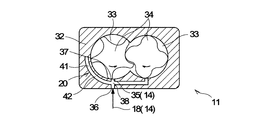
- a damper space 41 formed of a curved portion 42 which curves upward from the inner branch point 38 is used.
- the upper end side of the bending portion 42 shown in FIG. 25 is closed.
- the damper space 41 serving as the gas storage portion is located above the internal oil supply passage 35 in which the internal branch point 38 is located. Since the gas contained in the oil flowing through the internal oil flow passage 35 is retained in the damper space 41, the gas buffer unit 20 can operate stably, and the gas retained in the damper space 41 causes vibration or noise due to pulsation. Can be suppressed.
- a damper space 41 having an inclined straight portion 44 and a vertical straight portion 43 is used.
- the inclined straight portion 44 extends obliquely upward from the inner branch point 38 and communicates with the vertical straight portion 43.
- the upper end side of the vertical straight portion 43 is closed.
- the vertical straight portion 43 of the damper space 41 serving as the gas storage portion is located above the internal oil supply flow passage 35 in which the internal branch point 38 is located. Since the gas contained in the oil flowing through the internal oil flow passage 35 is retained in the damper space 41, the gas buffer unit 20 can operate stably, and the gas retained in the damper space 41 causes vibration or noise due to pulsation. Can be suppressed.
- a damper space 41 formed of an inclined straight portion 44 extending obliquely upward from the internal branch point 38 is used.
- the upper end side of the inclined straight portion 44 shown in FIG. 27 is closed.
- the inclined straight portion 44 of the damper space 41 serving as the gas storage portion is located above the internal oil supply flow passage 35 in which the internal branch point 38 is located. Since the gas contained in the oil flowing through the internal oil flow passage 35 is retained in the damper space 41, the gas buffer unit 20 can operate stably, and the gas retained in the damper space 41 causes vibration or noise due to pulsation. Can be suppressed.
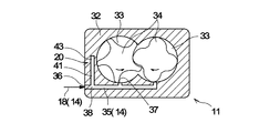
- the damper space 41 is provided upright with respect to the internal oil supply flow path 35 extending in the lateral direction from the left to the right.
- the damper space 41 includes a vertical straight portion 43 extending upward from the internal branch point 38, and the upper end side of the vertical straight portion 43 is closed.
- the vertical straight portion 43 of the damper space 41 serving as the gas storage portion is located above the internal oil supply flow passage 35 in which the internal branch point 38 is located. Since the gas contained in the oil flowing through the internal oil flow passage 35 is retained in the damper space 41, the gas buffer unit 20 can operate stably, and the gas retained in the damper space 41 causes vibration or noise due to pulsation. Can be suppressed.
- the structure in which the gas is retained in the inside of the damper space 41 made of a tubular body and the coolant is in direct contact with the retained gas has been described.
- a so-called accumulator in which the cooling fluid is in direct contact with the gas in the bladder by filling the gas in the bladder made of an elastically deformable film such as rubber as the gas buffer portion 20 and is there. That is, in the accumulator, the coolant and the gas are separated by the elastic membrane, and the pressure of the coolant is received by the gas through the elastic membrane.
- the said accumulator is used connecting to the middle of the piping which comprises the main flow path 14 in the oil-cooled-type screw compressor 1 of 1st Embodiment to 5th Embodiment mentioned above.
- the twin screw compressor which incorporated the screw rotor 34 of a male-female pair which meshes mutually was demonstrated.
- the present invention is suitably applied to a compressor having oil pulsation due to the fact that the teeth of the screw rotor 34 cross the main body oil supply hole (liquid supply hole) 37 and oil supply is interrupted. Therefore, the present invention is also applicable to a single screw compressor in which the gate of the gate rotor is engaged with the spiral groove of the screw rotor and the oil supply between the wall surface of the spiral groove and the gate is interrupted.
- cooling fluid may be water.
- air is exemplified as the gas to be compressed, the gas to be compressed may be nitrogen gas, oxygen gas, natural gas, city gas, hydrocarbon gas, refrigerant gas for a refrigerator, or the like.
- the gas storage portion 28 of the gas buffer portion 20 is a tubular body connected to a branch pipe branched from the main flow channel 14.
- the damper space 41 serving as the gas storage unit of the gas buffer unit 20 is a cavity formed inside the rotor casing 32 of the compressor main body 11.
- the gas storage part of the gas buffer part 20 may be an aspect provided with both a tubular body and a cavity.
- Oil-cooled screw compressor (liquid-cooled compressor) 11 compressor body 12 discharge flow path 13 oil separation and recovery unit 14 main refueling flow path (liquid supply flow path) 14A Cooling branch flow path 14B Bypass flow path 15 Oil cooler 17 Oil filter 18 Main body oil supply flow path (liquid supply flow path) Reference Signs List 19 temperature control valve 20 gas buffer portion 21 bearing oil supply passage 22 branch portion 23 inlet 24 damper main body (straight pipe) Reference Signs List 25 outlet 26 cap 27 branch connection port 28 gas storage unit 29 branch connection section 29A branch connection section 32 rotor casing 33 rotor chamber (gas compression space) 34 Screw rotor 35 Internal oil supply flow path (liquid supply flow path) 36 Oil supply connection hole 37 Main body oil supply hole (liquid supply hole) 38 Internal branch point 39 Bearing oil supply hole 40 Nipple pipe joint 41 Damper space 42 Curved portion 43 Vertical straight portion 44 Inclined straight portion 45 Elbow pipe joint 46, 47 Connection port 48 Horizontal straight portion 51 Cooling junction point 52 Oiling branch point
Landscapes
- Engineering & Computer Science (AREA)
- Mechanical Engineering (AREA)
- General Engineering & Computer Science (AREA)
- Applications Or Details Of Rotary Compressors (AREA)
- Compressor (AREA)
Abstract
液冷式圧縮機において、簡易な構成によって、配管の振動、及び、配管に接続された装置からの騒音を低減させる。油冷式スクリュ圧縮機(1)は、ガスを圧縮する圧縮機本体(11)と、圧縮機本体に形成されたガス圧縮空間(33)内に冷却液を供給する液供給孔(37)と連通する液供給流路(14)と、液供給流路を流れる冷却液の圧力を受けるガスを貯留するガス貯留部(28)を有するガス緩衝部(20)と、を備える。
Description
本発明は、液冷式圧縮機に関する。
液冷式圧縮機では、流体が圧縮されるのに伴って、流体温度が上昇するため、圧縮機本体内を冷却するために、冷却液を供給することが行われている。例えば、冷却液として油を用いた油冷式スクリュ圧縮機では、以下のような冷却が行われている。
油冷式スクリュ圧縮機は、ロータケーシング内に互いに噛み合う雌雄一対のスクリュロータを備え、このスクリュロータは、吸込側及び吐出側の軸受部によって回転可能に支持されている。スクリュ圧縮機内のガス圧縮空間であるロータ室及び軸受部等には、それぞれ、給油孔が設けられている。給油孔を通じてロータ室に供給された油は、スクリュロータを冷却する働きと、スクリュロータ同士の間、及びスクリュロータとロータケーシングの内壁部との間をシール及び潤滑する働きをしている。
スクリュロータが回転すると、スクリュロータの歯部が、ロータケーシングの内壁部に設けられた給油孔を横切ることにより、給油孔の開閉がなされる。給油孔の開閉で、油の流れが一時的に遮断されるため、油の脈動が生じる。油の脈動は、油を供給する配管に伝わって、配管が振動するようになる。そして、配管の振動に起因して、配管に接続された装置から騒音が発生する。圧縮機における従来技術に係る振動・騒音対策技術として、例えば、特許文献1が公知である。
特許文献1は、油分離器で分離されたガスを、ガス配管を通じて、油噴射配管を流れる作動流体油に混入させて作動流体油に圧縮性を持たせることにより、油噴射配管内部の圧力脈動を吸収させるスクリュ圧縮機を開示する。
しかしながら、特許文献1に開示された技術では、ガス配管を増設し、ガス配管及び油噴射配管のそれぞれに絞り弁及び絞り止弁を設けるとともに、一定量のガスを作動流体油に混入させるために、絞り弁及び絞り止弁を調整している。このように、特許文献1に開示された技術は、ガス配管、絞り弁及び絞り止弁を具備して、絞り弁及び絞り止弁の制御を行っていることから、非常に複雑なものになっている。
したがって、本発明の解決すべき技術的課題は、液冷式圧縮機において、簡易な構成によって、配管の振動、及び、配管に接続された装置からの騒音を低減させることである。
上記技術的課題を解決するために、本発明によれば、以下の液冷式圧縮機が提供される。
すなわち、本発明の液冷式圧縮機は、ガスを圧縮する圧縮機本体と、前記圧縮機本体に形成されたガス圧縮空間内に冷却液を供給する液供給孔と連通する液供給流路と、前記液供給流路を流れる冷却液の圧力を受けるガスを貯留するガス貯留部を有するガス緩衝部と、を備えることを特徴とする。
上記構成によれば、液供給流路を流れる冷却液の圧力が変動して脈動が発生したとき、脈動の圧力がガス緩衝部のガス貯留部に貯留されたガスで受けられて、ガスの圧縮作用により、脈動を吸収・減衰することができる。その結果、簡易な構成によって、配管の振動、及び、配管に接続された装置からの騒音を低減させることができる。
本発明は、上記特徴に加えて次のような特徴を備えることができる。
前記ガス緩衝部が、前記圧縮機本体及び前記圧縮機本体寄りの前記液供給流路の少なくとも1つに設けられている。当該構造によれば、ガス緩衝部が、脈動の発生源の近くに設けられているので、脈動による振動や騒音をより効果的に抑制することができる。
前記ガス緩衝部が、前記圧縮機本体寄りの前記液供給流路から分岐部で分岐された管状体であり、該管状体の末端部が閉じられている。当該構造によれば、ガス緩衝部として、既存の配管を利用することができるので、ガス緩衝部を簡易に且つ低コストで構成することができる。
前記ガス緩衝部が、前記圧縮機本体の前記液供給流路から分岐部で分岐され、当該圧縮機本体内に設けられた空間であり、該空間の末端部が閉じられている。当該構造によれば、ガス緩衝部として、圧縮機本体を利用することができるので、ガス緩衝部を簡易に且つ低コストで構成することができる。
前記ガス緩衝部が、前記液供給流路から分岐部で分岐して設けられている。当該構造によれば、ガス緩衝部として、液供給流路を利用することができるので、ガス緩衝部を簡易に且つ低コストで構成することができる。
前記ガス緩衝部の前記ガス貯留部が、前記分岐部の位置する前記液供給流路よりも上方に位置する。当該構造によれば、液供給流路を流れる冷却液に含まれるガスが、ガス貯留部に滞留するので、ガス緩衝部が安定して動作することができる。
前記ガス緩衝部の前記ガス貯留部に連通する開口部が、前記冷却液の流れ方向と対面する位置に配置されている。当該構造によれば、液供給流路を流れる冷却液に含まれるガスがガス緩衝部に流入しやすくなるので、ガス貯留部へのガスの滞留が容易になり、ガス緩衝部が安定して動作することができる。
前記圧縮機本体が、互いに噛み合う雌雄一対のスクリュロータを内蔵する。当該構造によれば、液供給流路での脈動に起因した振動や騒音が抑制されたスクリュ圧縮機が提供される。
本発明によれば、簡易な構成によって、配管の振動、及び、配管に接続された装置からの騒音を低減させることができる。
本発明に係る液冷式圧縮機1について、以下、液冷式圧縮機1として油冷式スクリュ圧縮機を用いた例で説明する。
(第1実施形態)
本発明の第1実施形態に係る液冷式圧縮機1について、図1を参照しながら説明する。図1は、液冷式圧縮機1の概略構成を示す。
(第1実施形態)
本発明の第1実施形態に係る液冷式圧縮機1について、図1を参照しながら説明する。図1は、液冷式圧縮機1の概略構成を示す。
液冷式圧縮機1は、図1に示すように、例えば、圧縮機本体11と油分離回収器13と油フィルタ17と油クーラ15と温度調整弁19とを備える。
液冷式圧縮機1は、例えば、図23等に示すように、冷却液として油を用いるとともに、互いに噛み合う雌雄一対のスクリュロータ34で、圧縮対象のガス(例えば、空気)を圧縮する、油冷式スクリュ圧縮機である。油冷式スクリュ圧縮機1は、互いに噛み合う雌雄一対のスクリュロータ34が、圧縮機本体11のロータケーシング32に形成されたロータ室(ガス圧縮空間)33内に収容されている。
図1に示すように、圧縮機本体11から延びる吐出流路12に油分離回収器13が設けられている。油冷式スクリュ圧縮機1の場合、圧縮機本体11から圧縮ガスが、油を伴って吐出され、油分離回収器13によって圧縮ガス及び油に分離される。圧縮ガスは、油分離回収器13の上部に接続された吐出流路12の部分から需要設備に向けて流れる。油分離回収器13で分離された油は、油分離回収器13の下部に形成される油溜まり部に一旦溜められる。
液冷式圧縮機1においては、油分離回収器13で分離された油が油分離回収器13から圧縮機本体11のガス圧縮空間まで流れる主給油流路(液供給流路)14が形成されている。主給油流路14(以下、単に主流路14という。)において、油分離回収器13の下流側には、油フィルタ17及び温度調整弁19が順に設けられている。主流路14が、温度調整弁19において、冷却分岐流路14Aとバイパス流路14Bとに分岐され、冷却分岐流路14A及びバイパス流路14Bが冷却合流ポイント51で合流する。冷却分岐流路14A上には、油クーラ15が配設されている。温度調整弁19により、油温が高い場合には油が冷却分岐流路14Aを流れ、油温が低い場合には油がバイパス流路14Bを流れる。
主流路14には、給油分岐ポイント52が設けられている。給油分岐ポイント52において、圧縮機本体11内の軸受・軸封部に通じる軸受給油流路21が主流路14から分岐している。圧縮機本体11のロータケーシング32においては、分岐ポイントから下流側の主流路14である本体給油流路(液供給流路)18に連通する本体給油孔37を通じてロータ室(ガス圧縮空間)33に給油される。そして、軸受給油流路21の軸受給油孔39を通じて軸受・軸封部に給油される。本体給油流路18からの油は、圧縮されるガスの冷却、スクリュロータ34間のシール及び潤滑のために使用される。軸受給油流路21からの油は、軸受・軸封部の潤滑及び軸封のために使用される。
図7及び図8は、ガス緩衝部20の第1例を示す。ガス緩衝部20は、主流路14の途中に設けられている。ガス緩衝部20は、分岐部22であるT字状に分岐した管継手で主流路(液供給流路)14から分岐しており分岐部22に接続された管状体であるダンパ本体24を備える。該ダンパ本体24の末端部がキャップ26で閉じられている。分岐部22である管継手は、入口23と出口25と分岐接続口27とを有する。入口23には主流路14の上流側配管が接続され、出口25には主流路14の下流側配管が接続され、分岐接続口27にはダンパ本体24が接続されている。ダンパ本体24の内部空間には、ガスを貯留するガス貯留部28が形成されている。主流路14を流れる油の圧力が変動して脈動が発生したとき、脈動の圧力がガス緩衝部20のガス貯留部28に貯留されたガスで受けられて、ガスの圧縮作用により、脈動を吸収・減衰することができる。
図7に示したガス緩衝部20では、油は、下方から上方に延在したあと右方に延在する主流路14に沿って流れる。ガス緩衝部20のガス貯留部28が、分岐部22の位置する主流路14よりも上方に位置する。主流路14を流れる油に含まれるガスが、ガス貯留部28に滞留するので、ガス緩衝部20が安定して動作することができる。また、分岐接続口27に接続されているガス貯留部28に通じる管状体の開口部が、油の流れ方向と対面する位置に配置されている。主流路14を流れる油に含まれるガスがダンパ本体24のガス貯留部28に流入しやすくなるので、ガス貯留部28へのガスの滞留が容易になり、ガス緩衝部20が安定して動作することができる。その結果、ガス貯留部28に滞留したガスによって、脈動による振動や騒音を抑制することができる。
なお、管状体であるダンパ本体24の内径は、主流路14の配管内径と同じであっても、異なっていてもよい。管径が異なる場合、ダンパ本体24の内径は、主流路14の配管内径に対して、例えば、0.5倍から2.0倍の範囲とすることができるが、当該数値に限定されるものでは無い。また、ダンパ本体24のガス貯留部28に滞留したガスは、キャップ26を緩めて積極的に脱気しない限り、容易に脱気されるものではない。そのため、液冷式圧縮機1の運転前にガス貯留部28をガスで充填した状態にしておけば、主流路14を流れる油に含まれるガスからの供給を受けてガスが溜まるのを待つ必要はない。
図1に戻って、第1実施形態に係る、主流路14におけるガス緩衝部20の配置位置について説明する。ガス緩衝部20が、圧縮機本体11寄りの主流路14に、すなわち、本体給油孔37と給油分岐ポイント52との間に位置する本体給油流路18の途中位置に設けられている。当該構成によれば、ガス緩衝部20が、脈動の発生源である圧縮機本体11の本体給油孔37の近くに設けられているので、脈動による振動や騒音をより効果的に抑制することができる。
実際に、上記ガス緩衝部20を有さない比較例と上記ガス緩衝部20を有する本発明の油冷式スクリュ圧縮機1とを準備して、定格の20%の回転数で運転させたときの両者の振動値を実測した。冷却合流ポイント51と給油分岐ポイント52との間に位置する主流路14(配管)の振動を振動分析計(株式会社リオン製VA-12)で計測した。その結果、比較例と比べ、本発明のガス緩衝部20を有する油冷式スクリュ圧縮機1では、振動のオーバーオール値が約85%小さくなることを確認した。
(第2実施形態)
図2は、本発明の第2実施形態に係る液冷式圧縮機1を示し、図1に示す第1実施形態に係る液冷式圧縮機1と共通する部分については、同一番号を付して説明を省略する。以下、第3実施形態から第6実施形態についても同様である。
図2は、本発明の第2実施形態に係る液冷式圧縮機1を示し、図1に示す第1実施形態に係る液冷式圧縮機1と共通する部分については、同一番号を付して説明を省略する。以下、第3実施形態から第6実施形態についても同様である。
第2実施形態の液冷式圧縮機1では、ガス緩衝部20が、主流路14の給油分岐ポイント52に設けられている。給油分岐ポイント52では、主流路14が、本体給油流路18と軸受給油流路21とに分岐されている。ガス緩衝部20を給油分岐ポイント52に設けることにより、既存の構成の変更(すなわち、配管の長さの変更)が最小限で済むため、低コスト化を実現することができる。したがって、第2実施形態においては、脈動による振動や騒音の抑制に加えて、既存構成の最小限の変更による低コスト化を実現することができる。
(第3実施形態)
図3に示す第3実施形態に係る液冷式圧縮機1では、油フィルタ17が、冷却合流ポイント51と給油分岐ポイント52との間に設けられている。第2実施形態と第3実施形態とを比較すると、油フィルタ17の配置位置が異なるだけであり、その他の構成においては差違が無い。上記第2実施形態の液冷式圧縮機1と同様に、第3実施形態に係る液冷式圧縮機1も、脈動による振動や騒音の抑制と、最小限での構成の変更とが可能になる。
図3に示す第3実施形態に係る液冷式圧縮機1では、油フィルタ17が、冷却合流ポイント51と給油分岐ポイント52との間に設けられている。第2実施形態と第3実施形態とを比較すると、油フィルタ17の配置位置が異なるだけであり、その他の構成においては差違が無い。上記第2実施形態の液冷式圧縮機1と同様に、第3実施形態に係る液冷式圧縮機1も、脈動による振動や騒音の抑制と、最小限での構成の変更とが可能になる。
(第4実施形態)
図4に示す第4実施形態に係る液冷式圧縮機1では、ガス緩衝部20が、主流路14の冷却合流ポイント51に設けられている。温度調整弁19及びバイパス流路14Bが一体的に構成される集合部品からなる場合、集合部品の下流端である冷却合流ポイント51にガス緩衝部20が設けることにより、脈動による振動や騒音の抑制と、最小限での構成の変更とが可能になる。
図4に示す第4実施形態に係る液冷式圧縮機1では、ガス緩衝部20が、主流路14の冷却合流ポイント51に設けられている。温度調整弁19及びバイパス流路14Bが一体的に構成される集合部品からなる場合、集合部品の下流端である冷却合流ポイント51にガス緩衝部20が設けることにより、脈動による振動や騒音の抑制と、最小限での構成の変更とが可能になる。
(第5実施形態)
図5に示す第5実施形態の液冷式圧縮機1では、複数のガス緩衝部20が、主流路14の本体給油流路18の途中位置に直列で設けられている。当該構成によれば、脈動による振動や騒音の抑制効果をより大きくすることができる。
図5に示す第5実施形態の液冷式圧縮機1では、複数のガス緩衝部20が、主流路14の本体給油流路18の途中位置に直列で設けられている。当該構成によれば、脈動による振動や騒音の抑制効果をより大きくすることができる。
上述した第1実施形態から第5実施形態の液冷式圧縮機1では、例えば、図9から図22に示した、第2例から第14例のガス緩衝部20を用いることができる。なお、第2実施形態及び第3実施形態においては、分岐部22として、T字状の管継手の代わりに十字状の管継手を適宜用いることができる。
まず、図9及び図10を参照しながら、第2例のガス緩衝部20を説明する。第2例のガス緩衝部20は、分岐部22であるT字状の管継手で主流路(液供給流路)14から分岐している。主流路14の途中に分岐部22の入口23と出口25とが接続されている。ガス貯留部28に通じる管状体であるエルボ管継手45が、分岐部22の分岐接続口27に接続されている。ダンパ本体24が、エルボ管継手45の接続口47に接続されている。すなわち、ダンパ本体24が、エルボ管継手45を介して分岐部22に接続されている。ガス緩衝部20のガス貯留部28が、分岐部22の位置する主流路14よりも上方に位置する。
図9において、油は、左方から右方に延在したあと紙面直交手前方向に延在する主流路14に沿って流れる。分岐部22の分岐接続口27に接続されているガス貯留部28に通じる管状体(エルボ管継手45)の開口部が、油の流れ方向と対面する位置に配置されている。主流路14を流れる油に含まれるガスがダンパ本体24のガス貯留部28に流入しやすくなるので、ガス貯留部28へのガスの滞留が容易になり、ガス緩衝部20が安定して動作することができる。その結果、ガス貯留部28に滞留したガスによって、脈動による振動や騒音を抑制することができる。
図11に示した第3例のガス緩衝部20は、分岐部22であるT字状の管継手で主流路(液供給流路)14から分岐している。T字状の分岐部22の上方に位置する分岐接続口27に対してダンパ本体24が接続されている。ガス緩衝部20において、ダンパ本体24のガス貯留部28が、分岐部22の位置する主流路14よりも上方に位置する。油は、左方から右方に延在する主流路14に沿って流れる。主流路14を流れる油に含まれるガスが、ガス貯留部28に滞留するので、ガス緩衝部20が安定して動作することができ、ガス貯留部28に滞留したガスによって、脈動による振動や騒音を抑制することができる。
図12に示した第4例のガス緩衝部20では、X軸,Y軸,Z軸の直交する3軸方向に分岐された分岐部22が使用されている。ガス緩衝部20において、ダンパ本体24のガス貯留部28が、分岐部22の位置する主流路14よりも上方に位置する。油は、左方から右方に延在したあと紙面直交手前方向に延在する主流路14に沿って流れる。主流路14を流れる油に含まれるガスが、ガス貯留部28に滞留するので、ガス緩衝部20が安定して動作することができ、ガス貯留部28に滞留したガスによって、脈動による振動や騒音を抑制することができる。
図13に示した第5例のガス緩衝部20は、分岐部22であるY字形の管継手で主流路(液供給流路)14から分岐している。ダンパ本体24が、Y字形の分岐部22の右斜め上方に位置する分岐接続口27に接続されている。ガス緩衝部20において、ダンパ本体24のガス貯留部28が、分岐部22の位置する主流路14よりも上方に位置する。油は、下方から左斜め上方に延在する主流路14に沿って流れる。主流路14を流れる油に含まれるガスが、ガス貯留部28に滞留するので、ガス緩衝部20が安定して動作することができ、ガス貯留部28に滞留したガスによって、脈動による振動や騒音を抑制することができる。
図14に示した第6例のガス緩衝部20は、分岐部22であるY字形の管継手で主流路(液供給流路)14から分岐している。ダンパ本体24が、Y字形の分岐部22の右斜め上方に位置する分岐接続口27に接続されている。ガス緩衝部20において、ダンパ本体24のガス貯留部28が、分岐部22の位置する主流路14よりも上方に位置する。油は、左斜め上方から下方に延在する主流路14に沿って流れる。主流路14を流れる油に含まれるガスが、ガス貯留部28に滞留するので、ガス緩衝部20が安定して動作することができ、ガス貯留部28に滞留したガスによって、脈動による振動や騒音を抑制することができる。
図15に示した第7例のガス緩衝部20は、分岐部22である右斜め下方に延在する分岐接続部29を有するT字形の管継手で主流路(液供給流路)14から分岐している。分岐接続部29の分岐接続口27に対して、ニップル管継手40が斜め下方に接続されている。エルボ管継手45が、ニップル管継手40の接続口46に接続され、ダンパ本体24が、エルボ管継手45の接続口47に接続されている。分岐接続部29及びニップル管継手40の傾斜角度は、主流路14を流れる油に含まれるガスが、ダンパ本体24のガス貯留部28に導入することができるように構成されている。当該傾斜角度は、主流路14を流れる油の流速に依存するが、例えば、略水平横方向に延びる主流路14に対して20度よりも小さい角度である。ダンパ本体24のガス貯留部28のが、分岐部22の位置する主流路14よりも上方に位置する。油は、左方から右方に延在する主流路14に沿って流れる。主流路14を流れる油に含まれるガスが、ガス貯留部28に滞留するので、ガス緩衝部20が安定して動作することができ、ガス貯留部28に滞留したガスによって、脈動による振動や騒音を抑制することができる。
図16に示した第8例のガス緩衝部20では、図15に示した分岐部22と同様のものが使用されているが、ニップル管継手40の管長が短く構成されている。ニップル管継手40の管長が短いほど、主流路14を流れる油に含まれるガスが、ダンパ本体24のガス貯留部28に導入しやすくなる。主流路14を流れる油に含まれるガスが、ガス貯留部28に滞留し易くなるので、ガス緩衝部20が安定して動作することができ、ガス貯留部28に滞留したガスによって、脈動による振動や騒音を抑制することができる。
図17に示した第9例のガス緩衝部20は、分岐部22である右斜め上方に延在する分岐接続部29Aを有するY字形の管継手で主流路(液供給流路)14から分岐している。分岐接続部29Aの分岐接続口27に対して、ダンパ本体24が右斜め上方に接続されている。ガス緩衝部20において、ダンパ本体24のガス貯留部28が、分岐部22の位置する主流路14よりも上方に位置する。油は、上方から下方に延在する主流路14に沿って流れる。主流路14を流れる油に含まれるガスが、ガス貯留部28に滞留するので、ガス緩衝部20が安定して動作することができ、ガス貯留部28に滞留したガスによって、脈動による振動や騒音を抑制することができる。
図18に示した第10例のガス緩衝部20では、図17に示した分岐部22と同様のものが使用されているが、油の流れ方向が図17に示したものと逆であり、油は、下方から上方に延在する主流路14に沿って流れる。ガス緩衝部20において、ダンパ本体24のガス貯留部28が、分岐部22の位置する主流路14よりも上方に位置する。主流路14を流れる油に含まれるガスが、ガス貯留部28に滞留するので、ガス緩衝部20が安定して動作することができ、ガス貯留部28に滞留したガスによって、脈動による振動や騒音を抑制することができる。
図19に示した第11例のガス緩衝部20は、分岐部22であるT字状の管継手で主流路(液供給流路)14から分岐している。管継手の上方に位置する分岐接続口27に対して、ニップル管継手40及びエルボ管継手45を介して、ダンパ本体24が接続されている。すなわち、ニップル管継手40の接続口46に対して、直角に曲がるエルボ管継手45が接続され、エルボ管継手45の接続口47に対して、ダンパ本体24が接続されている。ダンパ本体24は、分岐部22よりも上方に位置して、略水平横方向に延びている。ガス緩衝部20において、ダンパ本体24のガス貯留部28が、分岐部22の位置する主流路14よりも上方に位置する。油は、左方から右方に延在する主流路14に沿って流れる。主流路14を流れる油に含まれるガスが、ガス貯留部28に滞留するので、ガス緩衝部20が安定して動作することができ、ガス貯留部28に滞留したガスによって、脈動による振動や騒音を抑制することができる。
図20に示した第12例のガス緩衝部20では、図19に示したものと類似した構成であるが、曲がり角度の異なるエルボ管継手45が使用されている点が相違している。図20に示したエルボ管継手45では、曲がり角度が約45度であるが、曲がり角度は、0度から90度までの任意の角度とすることができる。ダンパ本体24は、分岐部22よりも上方に位置して、斜め上方に延びている。ガス緩衝部20において、ダンパ本体24のガス貯留部28が、分岐部22の位置する主流路14よりも上方に位置する。油は、左方から右方に延在する主流路14に沿って流れる。主流路14を流れる油に含まれるガスが、ガス貯留部28に滞留するので、ガス緩衝部20が安定して動作することができ、ガス貯留部28に滞留したガスによって、脈動による振動や騒音を抑制することができる。
図21に示した第13例のガス緩衝部20は、分岐部22である右斜め上方に延在する分岐接続部29Aを有するY字形の管継手で主流路(液供給流路)14から分岐している。分岐接続部29Aの分岐接続口27に対して、ダンパ本体24が右斜め上方に接続されている。ガス緩衝部20において、ダンパ本体24のガス貯留部28が、分岐部22の位置する主流路14よりも上方に位置する。油は、左方から右方に延在する主流路14に沿って流れる。主流路14を流れる油に含まれるガスが、ガス貯留部28に滞留するので、ガス緩衝部20が安定して動作することができ、ガス貯留部28に滞留したガスによって、脈動による振動や騒音を抑制することができる。
図22に示した第14例のガス緩衝部20は、分岐部22である左斜め上方に延在する分岐接続部29Aを有するY字形の管継手で主流路(液供給流路)14から分岐している。分岐接続部29Aの分岐接続口27に対して、ダンパ本体24が右斜め上方に接続されている。ガス緩衝部20において、ダンパ本体24のガス貯留部28が、分岐部22の位置する主流路14よりも上方に位置する。油は、左方から右方に延在する主流路14に沿って流れる。主流路14を流れる油に含まれるガスが、ガス貯留部28に滞留するので、ガス緩衝部20が安定して動作することができ、ガス貯留部28に滞留したガスによって、脈動による振動や騒音を抑制することができる。
次に、図6及び図23を参照しながら、第6実施形態の液冷式圧縮機1を説明する。
(第6実施形態)
図6に示す第6実施形態の液冷式圧縮機1では、ガス緩衝部20が、圧縮機本体11のロータケーシング32の内部に設けられている。ロータケーシング32の内部には、主流路(液供給流路)14である内部給油流路35が形成されている。内部給油流路35は、本体給油流路18に接続される給油接続孔36と、本体給油孔37とを連通する流路である。図23に示すように、本実施形態では、ロータケーシング32の下側に設けられた1つの給油接続孔36に対して2つの本体給油孔37が連通するように内部給油流路35が形成されている。ロータケーシング32においては、本体給油流路18が給油接続孔36を介して内部給油流路35と接続され、本体給油孔37を通じてロータ室(ガス圧縮空間)33に給油される。
図6に示す第6実施形態の液冷式圧縮機1では、ガス緩衝部20が、圧縮機本体11のロータケーシング32の内部に設けられている。ロータケーシング32の内部には、主流路(液供給流路)14である内部給油流路35が形成されている。内部給油流路35は、本体給油流路18に接続される給油接続孔36と、本体給油孔37とを連通する流路である。図23に示すように、本実施形態では、ロータケーシング32の下側に設けられた1つの給油接続孔36に対して2つの本体給油孔37が連通するように内部給油流路35が形成されている。ロータケーシング32においては、本体給油流路18が給油接続孔36を介して内部給油流路35と接続され、本体給油孔37を通じてロータ室(ガス圧縮空間)33に給油される。
ロータケーシング32の内部では、内部給油流路35の途中に設けられた内部分岐ポイント(分岐部)38から分岐したダンパ空間41が形成されている。第6実施形態に係るダンパ空間41は、ロータケーシング32の内部に形成された空洞であり、ガス緩衝部20におけるガス貯留部として働く。図23に示す第15例のダンパ空間41は、湾曲部42と縦ストレート部43とを有し、下端側は内部分岐ポイント38で開口しているものの、上端側は閉じられている。湾曲部42は、内部分岐ポイント38から湾曲しながら上方に延在して縦ストレート部43に連通している。ガス貯留部となるダンパ空間41の縦ストレート部43は、内部分岐ポイント38の位置する内部給油流路35よりも上方に位置している。湾曲部42が丸みを持っているので、内部給油流路35を流れる油に含まれるガスが、ダンパ空間41に導かれてダンパ空間41に滞留し易いので、ガス緩衝部20として安定して動作することができる。そして、ダンパ空間41に滞留したガスによって、脈動による振動や騒音を抑制することができる。
上述した第6実施形態の液冷式圧縮機1では、図24から図28に例示した、第16例から第20例のガス緩衝部20を用いることができる。
図24に示す第16例のガス緩衝部20では、横ストレート48と縦ストレート部43とを有する複数のダンパ空間41が使用されている。左右の横ストレート48は、左右の内部分岐ポイント38から横方向に延在して左右の縦ストレート部43にそれぞれ連通している。左右の縦ストレート部43の上端側は、それぞれ閉じられている。ガス貯留部となるダンパ空間41の縦ストレート部43は、内部分岐ポイント38の位置する内部給油流路35よりも上方に位置している。内部給油流路35を流れる油に含まれるガスが、左右のダンパ空間41に滞留するので、ガス緩衝部20として安定して動作することができ、左右のダンパ空間41に滞留したガスによって、脈動による振動や騒音を抑制することができる。
図25に示す第17例のガス緩衝部20では、内部分岐ポイント38から湾曲しながら上方に延在する湾曲部42からなるダンパ空間41が使用されている。図25に示す湾曲部42の上端側は、閉じられている。ガス貯留部となるダンパ空間41は、内部分岐ポイント38の位置する内部給油流路35よりも上方に位置している。内部給油流路35を流れる油に含まれるガスが、ダンパ空間41に滞留するので、ガス緩衝部20として安定して動作することができ、ダンパ空間41に滞留したガスによって、脈動による振動や騒音を抑制することができる。
図26に示す第18例のガス緩衝部20では、傾斜ストレート部44と縦ストレート部43とを有するダンパ空間41が使用されている。傾斜ストレート部44は、内部分岐ポイント38から斜め上方向に延在して縦ストレート部43に連通している。縦ストレート部43の上端側は、閉じられている。ガス貯留部となるダンパ空間41の縦ストレート部43は、内部分岐ポイント38の位置する内部給油流路35よりも上方に位置している。内部給油流路35を流れる油に含まれるガスが、ダンパ空間41に滞留するので、ガス緩衝部20が安定して動作することができ、ダンパ空間41に滞留したガスによって、脈動による振動や騒音を抑制することができる。
図27に示す第19例のガス緩衝部20では、内部分岐ポイント38から斜め上方に延在する傾斜ストレート部44からなるダンパ空間41が使用されている。図27に示す傾斜ストレート部44の上端側は、閉じられている。ガス貯留部となるダンパ空間41の傾斜ストレート部44は、内部分岐ポイント38の位置する内部給油流路35よりも上方に位置している。内部給油流路35を流れる油に含まれるガスが、ダンパ空間41に滞留するので、ガス緩衝部20が安定して動作することができ、ダンパ空間41に滞留したガスによって、脈動による振動や騒音を抑制することができる。
図28に示す第20例のガス緩衝部20では、左方から右方に横方向に延びる内部給油流路35に対してダンパ空間41が立設されている。ダンパ空間41は、内部分岐ポイント38から上方に延在する縦ストレート部43からなり、縦ストレート部43の上端側は、閉じられている。ガス貯留部となるダンパ空間41の縦ストレート部43は、内部分岐ポイント38の位置する内部給油流路35よりも上方に位置している。内部給油流路35を流れる油に含まれるガスが、ダンパ空間41に滞留するので、ガス緩衝部20として安定して動作することができ、ダンパ空間41に滞留したガスによって、脈動による振動や騒音を抑制することができる。
本発明の理解を容易にするために、具体的な構成や数字を用いて説明したが、この発明は、上述した各実施形態の具体的な構成や数字に限定されるものではなく、特許請求の範囲に記載した内容を逸脱しない範囲で考えられる各種の変形例を含むことができる。
上記第1実施形態から第5実施形態では、ガス緩衝部20として、管状体からなるダンパ空間41の内部にガスを滞留させて、冷却液が、滞留したガスと直接的に接する構成について説明した。しかしながら、ガス緩衝部20として、ゴムのような弾性的に変形可能な膜からなるブラダ内にガスを充填して、冷却液が、ブラダ内のガスと間接的に接する、いわゆるアキュムレータも利用可能である。すなわち、アキュムレータにおいては、弾性膜によって冷却液とガスとが仕切られて、冷却液の圧力は、弾性膜を介してガスで受けられる。当該アキュムレータは、上述した第1実施形態から第5実施形態の油冷式スクリュ圧縮機1において、主流路14を構成する配管の途中に接続して使用される。
また、上記各実施形態においては、互いに噛み合う雌雄一対のスクリュロータ34を内蔵する2軸スクリュ圧縮機について説明した。本発明は、スクリュロータ34の歯部が本体給油孔(液供給孔)37を横切って給油が断続されることに起因した、油の脈動を有する圧縮機に対して好適に適用される。したがって、スクリュロータの螺旋溝にゲートロータのゲートが噛み合い、螺旋溝の壁面とゲートとの間での給油が断続されるシングルスクリュ圧縮機にも適用可能である。
冷却液として油を例示したが、冷却液は水であってもよい。また、圧縮対象のガスとして空気を例示したが、圧縮対象のガスは、窒素ガス、酸素ガス、天然ガス、都市ガス、炭化水素ガス、冷凍機用冷媒ガス等であってもよい。
第1実施形態から第5実施形態では、ガス緩衝部20のガス貯留部28は、主流路14から分岐された分岐配管に接続された管状体である。第6実施形態では、ガス緩衝部20のガス貯留部として働くダンパ空間41は、圧縮機本体11のロータケーシング32の内部に形成された空洞である。ガス緩衝部20のガス貯留部は、管状体と空洞の両方を備える態様であってもよい。
1 油冷式スクリュ圧縮機(液冷式圧縮機)
11 圧縮機本体
12 吐出流路
13 油分離回収器
14 主給油流路(液供給流路)
14A 冷却分岐流路
14B バイパス流路
15 油クーラ
17 油フィルタ
18 本体給油流路(液供給流路)
19 温度調整弁
20 ガス緩衝部
21 軸受給油流路
22 分岐部
23 入口
24 ダンパ本体(直管)
25 出口
26 キャップ
27 分岐接続口
28 ガス貯留部
29 分岐接続部
29A 分岐接続部
32 ロータケーシング
33 ロータ室(ガス圧縮空間)
34 スクリュロータ
35 内部給油流路(液供給流路)
36 給油接続孔
37 本体給油孔(液供給孔)
38 内部分岐ポイント
39 軸受給油孔
40 ニップル管継手
41 ダンパ空間
42 湾曲部
43 縦ストレート部
44 傾斜ストレート部
45 エルボ管継手
46,47 接続口
48 横ストレート部
51 冷却合流ポイント
52 給油分岐ポイント
11 圧縮機本体
12 吐出流路
13 油分離回収器
14 主給油流路(液供給流路)
14A 冷却分岐流路
14B バイパス流路
15 油クーラ
17 油フィルタ
18 本体給油流路(液供給流路)
19 温度調整弁
20 ガス緩衝部
21 軸受給油流路
22 分岐部
23 入口
24 ダンパ本体(直管)
25 出口
26 キャップ
27 分岐接続口
28 ガス貯留部
29 分岐接続部
29A 分岐接続部
32 ロータケーシング
33 ロータ室(ガス圧縮空間)
34 スクリュロータ
35 内部給油流路(液供給流路)
36 給油接続孔
37 本体給油孔(液供給孔)
38 内部分岐ポイント
39 軸受給油孔
40 ニップル管継手
41 ダンパ空間
42 湾曲部
43 縦ストレート部
44 傾斜ストレート部
45 エルボ管継手
46,47 接続口
48 横ストレート部
51 冷却合流ポイント
52 給油分岐ポイント
Claims (8)
- ガスを圧縮する圧縮機本体と、
前記圧縮機本体に形成されたガス圧縮空間内に冷却液を供給する液供給孔と連通する液供給流路と、
前記液供給流路を流れる冷却液の圧力を受けるガスを貯留するガス貯留部を有するガス緩衝部と、を備える、液冷式圧縮機。 - 前記ガス緩衝部が、前記圧縮機本体及び前記圧縮機本体寄りの前記液供給流路の少なくとも1つに設けられている、請求項1に記載の液冷式圧縮機。
- 前記ガス緩衝部が、前記圧縮機本体寄りの前記液供給流路から分岐部で分岐された管状体であり、該管状体の末端部が閉じられている、請求項2に記載の液冷式圧縮機。
- 前記ガス緩衝部が、前記圧縮機本体の前記液供給流路から分岐部で分岐され、当該圧縮機本体内に設けられた空間であり、該空間の末端部が閉じられている、請求項2に記載の液冷式圧縮機。
- 前記ガス緩衝部が、前記液供給流路から分岐部で分岐して設けられている、請求項1に記載の液冷式圧縮機。
- 前記ガス緩衝部の前記ガス貯留部が、前記分岐部の位置する前記液供給流路よりも上方に位置する、請求項3から5のいずれか1項に記載の液冷式圧縮機。
- 前記ガス緩衝部の前記ガス貯留部に連通する開口部が、前記冷却液の流れ方向と対面する位置に配置されている、請求項3に記載の液冷式圧縮機。
- 前記圧縮機本体が、互いに噛み合う雌雄一対のスクリュロータを内蔵する、請求項1に記載の液冷式圧縮機。
Priority Applications (1)
| Application Number | Priority Date | Filing Date | Title |
|---|---|---|---|
| CN201680019994.9A CN107429681B (zh) | 2015-04-03 | 2016-02-29 | 液冷式压缩机 |
Applications Claiming Priority (2)
| Application Number | Priority Date | Filing Date | Title |
|---|---|---|---|
| JP2015-077257 | 2015-04-03 | ||
| JP2015077257A JP6472700B2 (ja) | 2015-04-03 | 2015-04-03 | 液冷式圧縮機 |
Publications (1)
| Publication Number | Publication Date |
|---|---|
| WO2016158152A1 true WO2016158152A1 (ja) | 2016-10-06 |
Family
ID=57005618
Family Applications (1)
| Application Number | Title | Priority Date | Filing Date |
|---|---|---|---|
| PCT/JP2016/056084 Ceased WO2016158152A1 (ja) | 2015-04-03 | 2016-02-29 | 液冷式圧縮機 |
Country Status (3)
| Country | Link |
|---|---|
| JP (1) | JP6472700B2 (ja) |
| CN (1) | CN107429681B (ja) |
| WO (1) | WO2016158152A1 (ja) |
Families Citing this family (1)
| Publication number | Priority date | Publication date | Assignee | Title |
|---|---|---|---|---|
| FI131891B1 (en) * | 2021-06-29 | 2026-02-02 | Tamturbo Oyj | Compressor |
Citations (3)
| Publication number | Priority date | Publication date | Assignee | Title |
|---|---|---|---|---|
| JPS5956312U (ja) * | 1982-10-06 | 1984-04-12 | トヨタ自動車株式会社 | サイドブランチ形消音器 |
| JPH1193875A (ja) * | 1997-07-25 | 1999-04-06 | Kobe Steel Ltd | 2段形油冷式スクリュ圧縮機 |
| JP2003193977A (ja) * | 2001-10-19 | 2003-07-09 | Denso Corp | 気体圧縮装置 |
Family Cites Families (7)
| Publication number | Priority date | Publication date | Assignee | Title |
|---|---|---|---|---|
| JP2710369B2 (ja) * | 1988-12-05 | 1998-02-10 | 電源開発株式会社 | 砂スラリー輸送用ピストンポンプの圧力脈動防止装置 |
| JPH11336683A (ja) * | 1998-05-21 | 1999-12-07 | Mayekawa Mfg Co Ltd | 油冷スクリュー圧縮機 |
| JP3891844B2 (ja) * | 2002-01-10 | 2007-03-14 | 株式会社神戸製鋼所 | 油冷式圧縮機 |
| JP4145830B2 (ja) * | 2004-04-09 | 2008-09-03 | 株式会社神戸製鋼所 | 油冷式圧縮機 |
| WO2009114820A2 (en) * | 2008-03-13 | 2009-09-17 | Aaf-Mcquay Inc. | High capacity chiller compressor |
| JP5650922B2 (ja) * | 2010-04-14 | 2015-01-07 | 株式会社神戸製鋼所 | 圧縮機 |
| CN103850941B (zh) * | 2012-11-29 | 2017-06-06 | 珠海格力电器股份有限公司 | 压缩机喷油装置、压缩机、压缩机润滑系统和制冷系统 |
-
2015
- 2015-04-03 JP JP2015077257A patent/JP6472700B2/ja active Active
-
2016
- 2016-02-29 WO PCT/JP2016/056084 patent/WO2016158152A1/ja not_active Ceased
- 2016-02-29 CN CN201680019994.9A patent/CN107429681B/zh active Active
Patent Citations (3)
| Publication number | Priority date | Publication date | Assignee | Title |
|---|---|---|---|---|
| JPS5956312U (ja) * | 1982-10-06 | 1984-04-12 | トヨタ自動車株式会社 | サイドブランチ形消音器 |
| JPH1193875A (ja) * | 1997-07-25 | 1999-04-06 | Kobe Steel Ltd | 2段形油冷式スクリュ圧縮機 |
| JP2003193977A (ja) * | 2001-10-19 | 2003-07-09 | Denso Corp | 気体圧縮装置 |
Also Published As
| Publication number | Publication date |
|---|---|
| CN107429681B (zh) | 2021-05-18 |
| JP2016196856A (ja) | 2016-11-24 |
| CN107429681A (zh) | 2017-12-01 |
| JP6472700B2 (ja) | 2019-02-20 |
Similar Documents
| Publication | Publication Date | Title |
|---|---|---|
| CN103486768B (zh) | 压缩装置以及包括该压缩装置的热力学系统 | |
| CN104220757B (zh) | 压缩机设备以及此种压缩机设备的应用 | |
| CN104897386B (zh) | 油气混输泵性能测试系统 | |
| JP4880517B2 (ja) | オイルバイパス付きコンプレッサ | |
| CN100373055C (zh) | 注水螺旋压缩机的部件 | |
| CN101581304A (zh) | 二级螺杆式压缩机及冷冻装置 | |
| CN105020119B (zh) | 流体阀 | |
| CN103518066B (zh) | 制冷循环装置 | |
| CN102369401A (zh) | 制冷循环装置 | |
| WO2014083901A1 (ja) | 圧縮機、冷凍サイクル装置およびヒートポンプ給湯装置 | |
| WO2016158152A1 (ja) | 液冷式圧縮機 | |
| CN102155406A (zh) | 一种涡旋压缩机的回油方法和回油结构 | |
| WO2019111650A1 (ja) | 液冷式圧縮機 | |
| JP4699501B2 (ja) | 容積形圧縮機 | |
| CN201330724Y (zh) | 用于离心式压缩机的轴封结构 | |
| JP2011202817A (ja) | 冷凍サイクル装置 | |
| CN109854502B (zh) | 具有以多个体积比的油喷射的螺杆式压缩机 | |
| CN104990307B (zh) | 空调器、压缩模块及压缩模块组 | |
| CN206917855U (zh) | 水蒸气螺杆式压缩机组 | |
| CN102455084B (zh) | 多个高压腔压缩机并联系统 | |
| CN207728563U (zh) | 具有回油结构的涡旋压缩机 | |
| CN104564784B (zh) | 一种用于离心压缩机油箱和吸气口的压力平衡结构 | |
| CN104074726B (zh) | 压缩机系统及其控制方法 | |
| CN222208282U (zh) | 截止装置、气液分离器和压缩机组件 | |
| CN104564824A (zh) | 泵及泵的使用方法 |
Legal Events
| Date | Code | Title | Description |
|---|---|---|---|
| 121 | Ep: the epo has been informed by wipo that ep was designated in this application |
Ref document number: 16772036 Country of ref document: EP Kind code of ref document: A1 |
|
| NENP | Non-entry into the national phase |
Ref country code: DE |
|
| 122 | Ep: pct application non-entry in european phase |
Ref document number: 16772036 Country of ref document: EP Kind code of ref document: A1 |