WO2016158098A1 - 光走査制御装置 - Google Patents
光走査制御装置 Download PDFInfo
- Publication number
- WO2016158098A1 WO2016158098A1 PCT/JP2016/055390 JP2016055390W WO2016158098A1 WO 2016158098 A1 WO2016158098 A1 WO 2016158098A1 JP 2016055390 W JP2016055390 W JP 2016055390W WO 2016158098 A1 WO2016158098 A1 WO 2016158098A1
- Authority
- WO
- WIPO (PCT)
- Prior art keywords
- light
- laser
- light amount
- scanning
- optical scanning
- Prior art date
- Legal status (The legal status is an assumption and is not a legal conclusion. Google has not performed a legal analysis and makes no representation as to the accuracy of the status listed.)
- Ceased
Links
Images


Classifications
-
- G—PHYSICS
- G02—OPTICS
- G02B—OPTICAL ELEMENTS, SYSTEMS OR APPARATUS
- G02B26/00—Optical devices or arrangements for the control of light using movable or deformable optical elements
- G02B26/08—Optical devices or arrangements for the control of light using movable or deformable optical elements for controlling the direction of light
- G02B26/10—Scanning systems
Definitions
- the present invention relates to an optical scanning control device.
- the optical scanning control device includes first detection means for directly detecting light emitted from the light source without going through the optical system, and second detection means for detecting light emitted from the light source through the optical system. .
- abnormality determination etc. can be performed based on the combination of the detection result of a 1st detection means and a 2nd detection means (for example, refer patent document 1).
- the first detection means and the second detection means both detect the amount of light before scanning the laser beam, so information such as the characteristic variation of the mirror that scans the laser beam. It is not possible to detect accurate light quantity information corresponding to an image actually displayed on a screen or the like. Therefore, there has been a problem that accurate light quantity control cannot be performed.
- This invention is made in view of said point, and makes it a subject to provide the optical scanning control apparatus which can perform exact light quantity control.
- the optical scanning control device (1) uses lasers (211R, 211G, 211B) that change the amount of light emitted according to the current value, and the light emitted from the lasers (211R, 211G, 211B) according to the video signal.
- Scanning means (310) that scans and forms an image on the screen (50), light quantity detection means (60) that detects the light quantity after scanning by the scanning means (310), and light quantity detection means (60) It is necessary to have control means (12) for controlling the current value of the laser (211R, 211G, 211B) based on the detected light quantity.
- an optical scanning control device capable of performing accurate light amount control.
- 1 is an external view (part 1) illustrating an optical scanning control device according to an embodiment; 1 is an external view (part 1) illustrating an optical scanning control device according to an embodiment; It is an external view (the 2) which illustrates the optical scanning control apparatus which concerns on this Embodiment. It is an external view (the 2) which illustrates the optical scanning control apparatus which concerns on this Embodiment.
- FIG. 1 is a block diagram illustrating an optical scanning control apparatus according to this embodiment.
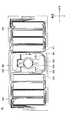
- FIG. 2 is a plan view illustrating an optical scanning unit constituting the optical scanning control device.
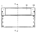
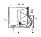
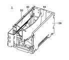
- 3A, 3B, 4A, and 4B are external views illustrating the optical scanning control device according to this embodiment.
- the optical scanning control device 1 includes, as main components, a circuit unit 10, a light source unit 20, an optical scanning unit 30, an optical unit 40, a screen 50, and a light quantity detection sensor 60. It is stored in the body 100.
- the optical scanning control device 1 is, for example, a laser scanning projector.
- the circuit unit 10 is a part that controls the light source unit 20 and the optical scanning unit 30, and can be configured by, for example, a system controller 11, a CPU (Central Processing Unit) 12, various driving circuits, and the like.
- a system controller 11 a CPU (Central Processing Unit) 12, various driving circuits, and the like.
- CPU Central Processing Unit
- the light source unit 20 includes an LD module 21, a temperature control unit 22, a temperature sensor 23, and a neutral density filter 24.
- the LD module 21 is a light amount detection sensor that monitors the light amounts of the lasers 211R, 211G, and 211B, and the lasers 211R, 211G, and 211B that change the amount of light emitted according to the current value (immediately after laser light emission). 215 and the like.
- the laser 211R is, for example, a red semiconductor laser, and can emit light having a wavelength ⁇ R (for example, 640 nm).
- the laser 211G is, for example, a green semiconductor laser, and can emit light having a wavelength ⁇ G (for example, 530 nm).
- the laser 211G is, for example, a blue semiconductor laser, and can emit light having a wavelength ⁇ B (for example, 445 nm).
- As the light quantity detection sensor 215, for example, a photodiode or the like can be used.
- the light quantity detection sensor 215 is a typical example of the second light quantity detection means according to the present invention.
- the light amount detection sensor 215 can be arranged at an arbitrary position where the light amount before scanning by the optical scanning unit 30 can be detected.
- the temperature control unit 22 can control the lasers 211R, 211G, and 211B to a predetermined temperature.
- the temperature sensor 23 can detect the temperatures of the lasers 211R, 211G, and 211B.
- a Peltier element can be used.
- a thermistor can be used.
- the optical scanning unit 30 is, for example, a MEMS (Micro Electro Mechanical System) that drives the mirror 310 with a piezoelectric element.
- the mirror 310 reflects the light (combined light) emitted from the lasers 211R, 211G, and 211B, scans the incident light in two dimensions in the horizontal and vertical directions according to the video signal, and couples it to the screen 50. It functions as scanning means for imaging.
- the mirror 310 is supported from both sides by torsion beams 331 and 332 constituting an axis (vertical axis for horizontal oscillation).
- Drive beams 351 and 352 are provided in pairs so as to sandwich the mirror 310 in a direction orthogonal to the torsion beams 331 and 332.
- the mirror 310 can be swung around the axis with the torsion beams 331 and 332 as axes.
- the direction in which the mirror 310 swings about the axes of the torsion beams 331 and 332 is hereinafter referred to as the horizontal direction.
- the horizontal displacement sensor 391 is a sensor that detects the horizontal tilt of the mirror 310 when the mirror 310 is oscillating in the horizontal direction.
- driving beams 371 and 372 are provided in pairs outside the driving beams 351 and 352.
- the piezoelectric element formed on each surface of the drive beams 371 and 372 can swing the mirror 310 in the vertical direction, which is a direction orthogonal to the horizontal direction.
- the vertical displacement sensors 395 and 396 are sensors that detect the vertical inclination of the mirror 310 in a state where the mirror 310 is swinging in the vertical direction.
- the optical scanning unit 30 is mounted on a ceramic package together with a drive circuit and the like, and is covered with a ceramic cover.
- the optical unit 40 is an optical system for projecting the light scanned by the light scanning unit 30 onto the screen 50.
- the reflection mirror 41, the reflection mirror 42, the reflection mirror 43, and the concave surface It can be configured including the mirror 44 and the like.
- the light incident on the optical unit 40 from the optical scanning unit 30 is converted into substantially parallel light by the concave mirror 44 and forms an image on the screen 50, and an image corresponding to the video signal is drawn on the screen 50.
- the screen 50 preferably has a function (such as a microlens array) that removes noise in a granular image called speckle.
- the light quantity detection sensor 60 is disposed at an arbitrary position where the light quantity after being scanned by the optical scanning unit 30 can be detected.
- the light amount detection sensor 60 can independently detect the respective light amounts of the lasers 211R, 211G, and 211B after being scanned by the optical scanning unit 30.
- the light quantity detection sensor 60 for example, one or a plurality of photodiodes can be used.
- the system controller 11 can control the deflection angle of the mirror 310.
- the system controller 11 monitors, for example, the horizontal and vertical inclinations of the mirror 310 obtained by the horizontal displacement sensor 391 and the vertical displacement sensors 395 and 396 via the buffer circuit 13, and sends an angle control signal to the mirror drive circuit 14.
- the mirror drive circuit 14 supplies a predetermined drive signal to the drive beams 351 and 352 and the drive beams 371 and 372 based on the angle control signal from the system controller 11 to drive (scan) the mirror 310 at a predetermined angle. can do.
- the system controller 11 can supply a digital video signal to the laser drive circuit 15, for example.
- the laser drive circuit 15 supplies a predetermined current to the lasers 211R, 211G, and 211B based on the video signal from the system controller 11. Accordingly, the lasers 211R, 211G, and 211B emit red, green, and blue light modulated according to the video signal, and a color image can be formed by combining these light.
- the CPU 12 can monitor the amount of light emitted from the bases of the lasers 211R, 211G, and 211B (immediately after the laser light is emitted) by the output of the light amount detection sensor 215 and supply a light amount control signal to the LD module 21, for example.
- the lasers 211 ⁇ / b> R, 211 ⁇ / b> G, and 211 ⁇ / b> B are current-controlled so as to obtain a predetermined output (light quantity) based on the light quantity control signal from the CPU 12.
- the light amount detection sensor 215 can include three sensors that independently detect the emitted light amounts of the lasers 211R, 211G, and 211B.
- the light amount detection sensor 215 may be composed of only one sensor.
- the emitted light amounts of the lasers 211R, 211G, and 211B can be controlled by sequentially emitting the lasers 211R, 211G, and 211B and sequentially detecting them with one sensor.
- the CPU 12 can monitor the temperatures of the lasers 211 R, 211 G, and 211 B based on the output of the temperature sensor 23 and supply a temperature control signal to the temperature control circuit 16. Then, the temperature control circuit 16 supplies a predetermined current to the temperature control unit 22 based on the temperature control signal from the CPU 12. Thereby, the temperature control part 22 is heated or cooled, and it can control so that each laser may become predetermined
- the light of each wavelength emitted from the lasers 211R, 211G, and 211B is synthesized by a dichroic mirror or the like, is reduced to a predetermined light quantity by the neutral density filter 24, and enters the mirror 310.
- the mirror 310 scans incident light two-dimensionally, and the scanning light is irradiated onto the screen 50 via the optical unit 40, and a two-dimensional image is formed on the screen 50.
- the function of the light quantity detection sensor 60 will be described later.
- the light amount detection sensor 215 for adjusting the light amount of each laser is mounted in the LD module 21, and the amount of light emitted from the bases of the lasers 211R, 211G, and 211B (immediately after laser light emission) is measured. Detected. However, since the image actually displayed by the optical scanning control device 1 is based on the light imaged on the screen 50, there is a case where correct adjustment cannot be performed by adjustment based on the laser light amount at the root (immediately after the laser light is emitted).
- the neutral density filter 24 since the neutral density filter 24 is provided on the optical path, the expected attenuation ratio cannot be obtained depending on the characteristics of the neutral density filter 24. Therefore, the amount of light after passing through the neutral density filter 24 is as expected. It may not be possible. Further, when there is a variation in the R / G / B dimming ratio of the neutral density filter 24, the white balance after passing through the neutral density filter 24 may be lost. Further, the characteristics of the optical scanning unit 30 may fluctuate due to temperature and aging degradation. Such a problem cannot be solved no matter how precisely the amount of light before passing through the optical scanning unit 30 is controlled by the light amount detection sensor 215.
- a light amount detection sensor 60 is provided as a light amount detection means for detecting the light amount after scanning by the optical scanning unit 30.
- the detection result of the light quantity detection sensor 60 is input to the CPU 12 which is a control means, and the CPU 12 supplies a light quantity control signal for controlling the current value of each laser to the LD module 21 based on the light quantity detected by the light quantity detection sensor 60.
- the CPU 12 supplies a light quantity control signal for controlling the current value of each laser to the LD module 21 based on the light quantity detected by the light quantity detection sensor 60.
- the light amount detection sensor 60 can independently detect the respective light amounts of the lasers 211R, 211G, and 211B, and the CPU 12 determines the current values of the respective lasers based on the respective light amounts detected by the light amount detection sensor 60. Can be controlled.
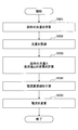
- FIG. 5 is an example of a flowchart of light amount control using the light amount detection sensor 60.
- the CPU 12 determines the expected amount of light after passing through the optical scanning unit 30 for the lasers 211R, 211G, and 211B based on the current laser current setting value and the setting value of the neutral density filter 24. Calculate
- step S502 the CPU 12 causes the lasers 211R, 211G, and 211B to emit light and actually measures the output value of the light amount detection sensor 60 corresponding to each laser.
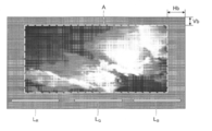
- the timing at which the CPU 12 causes the lasers 211R, 211G, and 211B to emit light in order to actually measure the output value of the light amount detection sensor 60 will be described with reference to FIG. FIG. 6 schematically shows an image and the like drawn on the screen 50.
- Hb and Vb shown in gray are a horizontal blanking interval and a vertical blanking interval, respectively.
- the horizontal blanking section Hb and the vertical blanking section Vb are areas scanned by the optical scanning unit 30, but this part is blocked by the housing 100. Therefore, what can be visually recognized as an image actually drawn on the screen 50 is only in the area A surrounded by a dotted line.
- the output value of the light quantity detection sensor 60 is measured without affecting the image drawn on the screen 50. be able to.
- the lasers 211R, 211G, and 211B can be sequentially turned on in the lower vertical blanking section Vb.
- L R is the light by the laser 211R
- the L B shows the light by the laser 211B.
- the light quantity detection sensor 60 three photodiodes having sensitivity to each wavelength of the laser beam L R , the laser beam L G , and the laser beam L B may be disposed.
- the light quantity detection sensor 60 is provided with a wavelength filter or the like, and a photodiode or the like that can simultaneously detect the wavelengths of the laser light L R , the laser light L G , and the laser light L B is disposed, the lasers 211R and 211G , And 211B may be turned on simultaneously.
- step S503 the CPU 12 determines the expected light amount calculated in step S501 and the light amount actually measured in step S502 (the output value of the light amount detection sensor 60) for the lasers 211R, 211G, and 211B. And calculate the difference.
- step S504 the CPU 12 calculates current change values of the lasers 211R, 211G, and 211B so that the difference calculated in step S503 is zero.
- step S505 the CPU 12 changes the current values of the lasers 211R, 211G, and 211B to the current change values calculated in step S504.
- the lasers 211R, 211G, and 211B are controlled by the CPU 12 so that the amount of light after scanning by the optical scanning unit 30 matches the expected amount of light.
- the control using the light quantity detection sensor 60 is used in combination with the control using the light quantity detection sensor 215, and the current value of each laser is controlled based on the light quantity detected by the light quantity detection sensor 60 and the light quantity detected by the light quantity detection sensor 215.
- the control can be performed based on the difference between the output value of the light amount detection sensor 215 and the output value of the light amount detection sensor 60.
- the control using the light amount detection sensor 215 is not performed, and the control can be performed using only the light amount detection sensor 60.
- the temperature characteristics of the lasers 211R, 211G, and 211B themselves, the change in the light amount due to aging, the variation or aging of the dimming ratio of the neutral density filter 24, the frequency characteristics of the neutral density filter 24, the temperature and the aging degradation. It is possible to compensate for the characteristic variation of the optical scanning unit 30 due to the above.
- the frequency characteristic of the neutral density filter 24 is a difference in dimming ratio with respect to each of R / G / B light.
- the light amount detection sensor 60 is disposed at a stage after the optical scanning unit 30, and the light amount after the scanning by the optical scanning unit 30 is controlled to be constant, thereby reducing the neutral density filter. 24 and the light quantity of the laser light including the fluctuation of the characteristics of the optical scanning unit 30 can be controlled. As a result, the correct light amount control necessary for the image actually displayed on the screen 50 can be performed, and a more precise color balance can be obtained.
- the light amount detection sensor 60 may be disposed at any position as long as the light amount after scanning by the optical scanning unit 30 can be detected. However, if it is arranged between the optical unit 40 and the screen 50 (for example, the rear stage of the concave mirror 44 in FIG. 3B), the amount of light after passing through the optical unit 40 can be detected, and therefore included in the optical unit 40. This is preferable in that it can compensate for characteristic variations of each optical device.
- the optical scanning control device according to the present invention is applied to a laser scanning projector.
- the optical scanning control device according to the present invention can be applied to various devices in which it is preferable to control the amount of light after scanning to be constant. Examples of such devices include an on-vehicle head-up display, a laser printer, a laser scanning epilator, a laser head lamp, and a laser radar.
Landscapes
- Physics & Mathematics (AREA)
- General Physics & Mathematics (AREA)
- Optics & Photonics (AREA)
- Mechanical Optical Scanning Systems (AREA)
Abstract
本光走査制御装置は、電流値に応じて出射する光量が変化するレーザと、前記レーザから出射された光を映像信号に応じて走査し、スクリーンに結像させる走査手段と、前記走査手段で走査した後の光量を検出する光量検出手段と、前記光量検出手段で検出した光量に基づいて、前記レーザの電流値を制御する制御手段と、を有する。
Description
本発明は、光走査制御装置に関する。
レーザ光を走査して画像を表示する光走査制御装置が知られている。この光走査制御装置は、光源から発せられる光を光学系を介さずに直接検出する第1検出手段と、光源から発せられる光を光学系を介して検出する第2検出手段とを備えている。そして、第1検出手段と第2検出手段との検出結果の組み合わせに基づいて、異常判定等を行うことができる(例えば、特許文献1参照)。
しかしながら、上記の光走査制御装置では、第1検出手段と第2検出手段は、何れもレーザ光を走査する前の光量を検出しているため、レーザ光を走査するミラーの特性変動等の情報を含めた、実際にスクリーン等に表示される画像に対応した正確な光量の情報を検出できない。そのため、正確な光量制御を行うことができないという問題があった。
本発明は、上記の点に鑑みてなされたもので、正確な光量制御を行うことが可能な光走査制御装置を提供することを課題とする。
本光走査制御装置(1)は、電流値に応じて出射する光量が変化するレーザ(211R、211G、211B)と、前記レーザ(211R、211G、211B)から出射された光を映像信号に応じて走査し、スクリーン(50)に結像させる走査手段(310)と、前記走査手段(310)で走査した後の光量を検出する光量検出手段(60)と、前記光量検出手段(60)で検出した光量に基づいて、前記レーザ(211R、211G、211B)の電流値を制御する制御手段(12)と、を有することを要件とする。
なお、上記括弧内の参照符号は、理解を容易にするために付したものであり、一例にすぎず、図示の態様に限定されるものではない。
開示の技術によれば、正確な光量制御を行うことが可能な光走査制御装置を提供できる。
以下、図面を参照して発明を実施するための形態について説明する。各図面において、同一構成部分には同一符号を付し、重複した説明を省略する場合がある。
図1は、本実施の形態に係る光走査制御装置を例示するブロック図である。図2は、光走査制御装置を構成する光走査部を例示する平面図である。図3A、図3B、図4A及び図4Bは、本実施の形態に係る光走査制御装置を例示する外観図である。
(光走査制御装置の概略構成)
まず、図1~図4Bを参照して、光走査制御装置1の概略構成について説明する。光走査制御装置1は、主要な構成要素として、回路部10と、光源部20と、光走査部30と、光学部40と、スクリーン50と、光量検出センサ60とを有し、これらは筐体100に格納されている。光走査制御装置1は、例えば、レーザ走査型プロジェクタである。
まず、図1~図4Bを参照して、光走査制御装置1の概略構成について説明する。光走査制御装置1は、主要な構成要素として、回路部10と、光源部20と、光走査部30と、光学部40と、スクリーン50と、光量検出センサ60とを有し、これらは筐体100に格納されている。光走査制御装置1は、例えば、レーザ走査型プロジェクタである。
回路部10は、光源部20や光走査部30を制御する部分であり、例えば、システムコントローラ11やCPU(Central Processing Unit)12、各種駆動回路等により構成することができる。
光源部20は、LDモジュール21と、温度制御部22と、温度センサ23と、減光フィルタ24とを有する。
LDモジュール21は、電流値に応じて出射する光量が変化するレーザ211R、211G、及び211Bや、レーザ211R、211G、及び211Bの夫々の直近(レーザー光出射直後)の光量をモニタする光量検出センサ215等を備えている。レーザ211Rは、例えば、赤色半導体レーザであり、波長λR(例えば、640nm)の光を出射することができる。レーザ211Gは、例えば、緑色半導体レーザであり、波長λG(例えば、530nm)の光を出射することができる。レーザ211Gは、例えば、青色半導体レーザであり、波長λB(例えば、445nm)の光を出射することができる。光量検出センサ215としては、例えば、フォトダイオード等を用いることができる。
なお、光量検出センサ215は、本発明に係る第2の光量検出手段の代表的な一例である。光量検出センサ215は、光走査部30で走査する前の光量を検出できる任意の位置に配置することができる。
温度制御部22は、レーザ211R、211G、及び211Bを所定の温度に制御することができる。温度センサ23は、レーザ211R、211G、及び211Bの夫々の温度を検出することができる。温度制御部22としては、例えば、ペルチェ素子を用いることができる。温度センサ23としては、例えば、サーミスタを用いることができる。
光走査部30は、例えば、圧電素子によりミラー310を駆動させるMEMS(Micro Electro Mechanical System)である。ミラー310は、レーザ211R、211G、及び211Bから出射された光(合成後の光)を反射させ、映像信号に応じて入射光を水平方向及び垂直方向の2次元に走査してスクリーン50に結像させる走査手段として機能する。
具体的には、図2に示すように、ミラー310は、軸(水平揺動用垂直軸)を構成する捻れ梁331及び332により両側から支持されている。捻れ梁331及び332と直交する方向に、ミラー310を挟むように、駆動梁351及び352が対をなして設けられている。駆動梁351及び352の夫々の表面に形成された圧電素子により、捻れ梁331及び332を軸として、ミラー310を軸周りに揺動させることができる。ミラー310が捻れ梁331及び332の軸周りに揺動する方向を、以後、水平方向と呼ぶ。駆動梁351及び352による水平駆動には、例えば共振振動が用いられ、高速にミラー310を駆動することができる。水平変位センサ391は、ミラー310が水平方向に揺動している状態におけるミラー310の水平方向の傾き具合を検出するセンサである。
又、駆動梁351及び352の外側には、駆動梁371及び372が対をなして設けられている。駆動梁371及び372の夫々の表面に形成された圧電素子により、ミラー310を水平方向と直交する方向である垂直方向に揺動させることができる。垂直変位センサ395及び396は、ミラー310が垂直方向に揺動している状態におけるミラー310の垂直方向の傾き具合を検出するセンサである。なお、光走査部30は、例えば、ユニット150(図3B参照)において、駆動回路等と共にセラミックパッケージに搭載され、セラミックカバーに覆われている。
光学部40は、光走査部30に走査された光をスクリーン50に投射するための光学系であり、例えば、図3B等に示すように、反射ミラー41、反射ミラー42、反射ミラー43、凹面ミラー44等を含んで構成することができる。光走査部30から光学部40に入射した光は、凹面ミラー44により略平行光とされてスクリーン50に結像し、スクリーン50に映像信号に応じた画像が描画される。スクリーン50は、スペックルと呼ばれる粒状に見える画像のノイズを除去する機能(マイクロレンズアレイ等)を備えていることが好ましい。
光量検出センサ60は、光走査部30で走査した後の光量を検出できる任意の位置に配置されている。光量検出センサ60は、光走査部30で走査した後のレーザ211R、211G、及び211Bの夫々の光量を独立に検出可能である。光量検出センサ60としては、例えば、1つ又は複数のフォトダイオード等を用いることができる。
(光走査制御装置の概略動作)
次に、光走査制御装置1の概略動作について説明する。システムコントローラ11は、例えば、ミラー310の振れ角制御を行うことができる。システムコントローラ11は、例えば、水平変位センサ391、垂直変位センサ395及び396で得られるミラー310の水平方向及び垂直方向の傾きをバッファ回路13を介してモニタし、ミラー駆動回路14に角度制御信号を供給することができる。そして、ミラー駆動回路14は、システムコントローラ11からの角度制御信号に基づいて、駆動梁351及び352、駆動梁371及び372に所定の駆動信号を供給し、ミラー310を所定角度に駆動(走査)することができる。
次に、光走査制御装置1の概略動作について説明する。システムコントローラ11は、例えば、ミラー310の振れ角制御を行うことができる。システムコントローラ11は、例えば、水平変位センサ391、垂直変位センサ395及び396で得られるミラー310の水平方向及び垂直方向の傾きをバッファ回路13を介してモニタし、ミラー駆動回路14に角度制御信号を供給することができる。そして、ミラー駆動回路14は、システムコントローラ11からの角度制御信号に基づいて、駆動梁351及び352、駆動梁371及び372に所定の駆動信号を供給し、ミラー310を所定角度に駆動(走査)することができる。
又、システムコントローラ11は、例えば、ディジタルの映像信号をレーザ駆動回路15に供給することができる。そして、レーザ駆動回路15は、システムコントローラ11からの映像信号に基づいて、レーザ211R、211G、及び211Bに所定の電流を供給する。これにより、レーザ211R、211G、及び211Bが映像信号に応じて変調された赤色、緑色、及び青色の光を発し、これらを合成することでカラーの画像を形成することができる。
CPU12は、例えば、レーザ211R、211G、及び211Bの根元(レーザー光出射直後)の出射光量を光量検出センサ215の出力によりモニタし、LDモジュール21に光量制御信号を供給することができる。レーザ211R、211G、及び211Bは、CPU12からの光量制御信号に基づいて、所定の出力(光量)になるように電流制御される。
なお、光量検出センサ215は、レーザ211R、211G、及び211Bの出射光量を独立に検出する3つのセンサを含む構成とすることができる。或いは、光量検出センサ215は、1つのセンサのみから構成してもよい。この場合には、レーザ211R、211G、及び211Bを順次発光させて、1つのセンサで順次検出することで、レーザ211R、211G、及び211Bの出射光量の制御が可能となる。
又、CPU12は、レーザ211R、211G、及び211Bの温度を温度センサ23の出力によりモニタし、温度制御回路16に温度制御信号を供給することができる。そして、温度制御回路16は、CPU12から温度制御信号に基づいて、温度制御部22に所定の電流を供給する。これにより、温度制御部22が加熱又は冷却され、各レーザが所定の温度になるように制御することができる。
レーザ211R、211G、及び211Bから出射された各波長の光は、ダイクロイックミラー等により合成され、減光フィルタ24により所定の光量に減光されてミラー310に入射する。ミラー310は、入射光を2次元に走査し、走査光は光学部40を介してスクリーン50に照射され、スクリーン50に2次元像が形成される。なお、光量検出センサ60の機能については、後述する。
(レーザの光量制御)
前述のように、各レーザの光量調整を実施するための光量検出センサ215はLDモジュール21の中に実装されており、レーザ211R、211G、及び211Bの根元(レーザー光出射直後)の出射光量を検出している。しかしながら、光走査制御装置1で実際に表示される画像はスクリーン50に結像した光によるので、根元(レーザー光出射直後)のレーザ光量による調整では正しい調整ができない場合がある。
前述のように、各レーザの光量調整を実施するための光量検出センサ215はLDモジュール21の中に実装されており、レーザ211R、211G、及び211Bの根元(レーザー光出射直後)の出射光量を検出している。しかしながら、光走査制御装置1で実際に表示される画像はスクリーン50に結像した光によるので、根元(レーザー光出射直後)のレーザ光量による調整では正しい調整ができない場合がある。
例えば、光路上に減光フィルタ24を設けているので、減光フィルタ24の特性によっては、期待通りの減光比が得られないことから、減光フィルタ24を通過後の光量が期待通りにならない場合がある。又、減光フィルタ24のR/G/B夫々の減光比にばらつきがある場合に至っては、減光フィルタ24を通過後のホワイトバランスが崩れてしまうおそれがある。又、温度や経年劣化により、光走査部30の特性が変動する場合もある。このような問題は、光量検出センサ215により、光走査部30を通過前の光量を如何に精密に制御しても解決することはできない。
そこで、光走査制御装置1では、光走査部30で走査した後の光量を検出する光量検出手段として、光量検出センサ60を設けている。光量検出センサ60の検出結果は制御手段であるCPU12に入力され、CPU12は光量検出センサ60で検出した光量に基づいて、各レーザの電流値を制御する光量制御信号をLDモジュール21に供給することができる。これにより、減光フィルタ24や光走査部30の特性の変動を含めたレーザ光の光量を検出できるため、スクリーン50に実際に表示される画像に対応した正確な光量制御を行うことが可能となる。なお、光量検出センサ60は、レーザ211R、211G、及び211Bの夫々の光量を独立に検出可能であり、CPU12は、光量検出センサ60で検出した夫々の光量に基づいて、夫々のレーザの電流値を制御すことができる。
以下、図5及び図6を参照しながら、光走査制御装置1における光量検出センサ60を用いた光量制御について更に詳しく説明する。図5は、光量検出センサ60を用いた光量制御のフローチャートの一例である。まず、ステップS501において、CPU12は、レーザ211R、211G、及び211Bについて、現在のレーザの電流設定値と、減光フィルタ24の設定値とに基づいて、光走査部30を通過後の期待の光量を計算する。
次に、ステップS502において、CPU12は、レーザ211R、211G、及び211Bを発光させ、各レーザに対応する光量検出センサ60の出力値を実測する。ここで、図6を参照しながら、CPU12が、光量検出センサ60の出力値を実測するために、レーザ211R、211G、及び211Bを発光させるタイミングについて説明する。図6では、スクリーン50に描画される画像等を模式的に示している。
図6において、グレーで示したHb及びVbは、夫々、水平ブランキング区間及び垂直ブランキング区間である。水平ブランキング区間Hb及び垂直ブランキング区間Vbは、光走査部30により走査される領域であるが、この部分は筐体100で遮られる。そのため、実際にスクリーン50に描画された画像として視認できるのは、点線で囲んだ領域A内のみである。
そこで、水平ブランキング区間Hb又は垂直ブランキング区間Vbで、光量実測用のレーザを発光させれば、スクリーン50に描画された画像に影響を与えることなく、光量検出センサ60の出力値を実測することができる。
例えば、図6に示すように、下側の垂直ブランキング区間Vbで、レーザ211R、211G、及び211Bを順次点灯させることができる。ここで、LRはレーザ211Rによる光、LGはレーザ211Gによる光、LBはレーザ211Bによる光を示している。
この場合には、光量検出センサ60として、レーザ光LR、レーザ光LG、レーザ光LBの各波長に感度を有する3つのフォトダイオード等を配置しておけばよい。
この場合には、光量検出センサ60として、レーザ光LR、レーザ光LG、レーザ光LBの各波長に感度を有する3つのフォトダイオード等を配置しておけばよい。
或いは、光量検出センサ60として、波長フィルタ等を備えており、レーザ光LR、レーザ光LG、レーザ光LBの波長を同時に検出できるフォトダイオード等を配置した場合には、レーザ211R、211G、及び211Bを同時に点灯させてもよい。
図5の説明に戻り、次に、ステップS503において、CPU12は、レーザ211R、211G、及び211Bについて、ステップS501で計算した期待の光量とステップS502で実測した光量(光量検出センサ60の出力値)との差異を計算する。
次に、ステップS504において、CPU12は、ステップS503で計算した差異がゼロとなるような、レーザ211R、211G、及び211Bの夫々の電流変更値を計算する。次に、ステップS505において、CPU12は、レーザ211R、211G、及び211Bの電流値を、ステップS504で計算した電流変更値に変更する。
これにより、レーザ211R、211G、及び211Bは、光走査部30で走査した後の光量が期待の光量と一致するように、CPU12により制御される。光量検出センサ60を用いた制御を、光量検出センサ215を用いた制御と併用し、光量検出センサ60で検出した光量及び光量検出センサ215で検出した光量に基づいて各レーザの電流値を制御することで、より精度の高い光量制御を行うことが可能である。この場合、例えば、光量検出センサ215の出力値と光量検出センサ60の出力値との差分に基づいて制御することができる。
但し、光量検出センサ215を用いた制御は行わず、光量検出センサ60のみを用いて制御することも可能である。この場合にも、レーザ211R、211G、及び211B自身の温度特性や経年変化による光量の変化、減光フィルタ24の減光比のばらつきや経年変化、減光フィルタ24の周波数特性、温度や経年劣化による光走査部30の特性変動を補償可能である。なお、減光フィルタ24の周波数特性とは、R/G/B夫々の光に対する減光比の差異である。
このように、光走査制御装置1において、光走査部30よりも後段に光量検出センサ60を配置し、光走査部30で走査した後の光量を一定に保つ制御を行うことにより、減光フィルタ24や光走査部30の特性の変動を含めたレーザ光の光量を制御できる。その結果、スクリーン50に実際に表示される画像に必要な正しい光量制御が可能となり、より精密なカラーバランスを得ることができる。
なお、光量検出センサ60は、光走査部30で走査した後の光量を検出できれば何れの位置に配置しても構わない。但し、光学部40とスクリーン50との間(例えば、図3Bの凹面ミラー44の後段)に配置した場合には、光学部40を通過した後の光量を検出できるため、光学部40に含まれる各光学デバイスの特性ばらつきも補償できる点で好適である。
以上、好ましい実施の形態について詳説したが、上述した実施の形態に制限されることはなく、特許請求の範囲に記載された範囲を逸脱することなく、上述した実施の形態に種々の変形及び置換を加えることができる。
例えば、上記の実施の形態では、本発明に係る光走査制御装置をレーザ走査型プロジェクタに適用する例を示した。しかし、これは一例であり、本発明に係る光走査制御装置は、走査後の光量を一定に制御することが好ましい様々な機器に適用可能である。このような機器としては、例えば、車載用のヘッドアップディスプレイ、レーザプリンタ、レーザ走査型脱毛器、レーザヘッドランプ、レーザーレーダ等を挙げることができる。
又、上記の実施の形態では、3つのレーザを有する例を示したが、レーザは最低1つ有していればよい。この場合、単色の光走査制御装置を実現できる。
1 光走査制御装置
10 回路部
11 システムコントローラ
12 CPU
13 バッファ回路
14 ミラー駆動回路
15 レーザ駆動回路
16 温度制御回路
20 光源部
21 LDモジュール
22 温度制御部
23 温度センサ
24 減光フィルタ
30 光走査部
40 光学部
41、42、43 反射ミラー
44 凹面ミラー
50 スクリーン
60 光量検出センサ
100 筐体
150 ユニット
211R、211G、211B レーザ
215 光量検出センサ
310 ミラー
351、352、371、372 駆動梁
391 水平変位センサ
395、396 垂直変位センサ
以上本発明の好ましい実施例について詳述したが、本発明は係る特定の実施形態に限定されるものではなく、特許請求の範囲に記載された本発明の要旨の範囲内において、種々の変形、変更が可能である。
10 回路部
11 システムコントローラ
12 CPU
13 バッファ回路
14 ミラー駆動回路
15 レーザ駆動回路
16 温度制御回路
20 光源部
21 LDモジュール
22 温度制御部
23 温度センサ
24 減光フィルタ
30 光走査部
40 光学部
41、42、43 反射ミラー
44 凹面ミラー
50 スクリーン
60 光量検出センサ
100 筐体
150 ユニット
211R、211G、211B レーザ
215 光量検出センサ
310 ミラー
351、352、371、372 駆動梁
391 水平変位センサ
395、396 垂直変位センサ
以上本発明の好ましい実施例について詳述したが、本発明は係る特定の実施形態に限定されるものではなく、特許請求の範囲に記載された本発明の要旨の範囲内において、種々の変形、変更が可能である。
本国際出願は、2015年3月31日に出願した日本国特許出願2015-071823号に基づく優先権を主張するものであり、日本国特許出願2015-071823号の全内容をここに本国際出願に援用する。
Claims (8)
- 電流値に応じて出射する光量が変化するレーザと、
前記レーザから出射された光を映像信号に応じて走査し、スクリーンに結像させる走査手段と、
前記走査手段で走査した後の光量を検出する光量検出手段と、
前記光量検出手段で検出した光量に基づいて、前記レーザの電流値を制御する制御手段と、を有する光走査制御装置。 - 前記レーザを複数有し、
前記光量検出手段は、夫々の前記レーザが出射して前記走査手段で走査した後の夫々の光量を検出可能に構成され、
前記制御手段は、前記光量検出手段で検出した夫々の光量に基づいて、夫々の前記レーザの電流値を制御する請求項1記載の光走査制御装置。 - 前記レーザは、赤色レーザ、緑色レーザ、及び青色レーザを含む請求項2記載の光走査制御装置。
- 前記制御手段は、前記走査手段で走査した後の光量が期待の光量と一致するように、前記レーザの電流値を制御する請求項1記載の光走査制御装置。
- 前記走査手段と前記スクリーンとの間の光路上に光学部を有し、
前記光量検出手段は、前記光学部を通過した後の光量を検出する請求項1記載の光走査制御装置。 - 前記走査手段には、減光フィルタを介した光が入射する請求項1記載の光走査制御装置。
- 前記制御手段は、前記レーザの電流値を制御するために、水平ブランキング区間又は垂直ブランキング区間において、前記レーザを発光させる請求項1記載の光走査制御装置。
- 前記走査手段で走査する前の光量を検出する第2の光量検出手段を有し、
前記制御手段は、前記光量検出手段で検出した光量、及び前記第2の光量検出手段で検出した光量に基づいて、前記レーザの電流値を制御する請求項1記載の光走査制御装置。
Applications Claiming Priority (2)
| Application Number | Priority Date | Filing Date | Title |
|---|---|---|---|
| JP2015-071823 | 2015-03-31 | ||
| JP2015071823A JP6663102B2 (ja) | 2015-03-31 | 2015-03-31 | 光走査制御装置 |
Publications (1)
| Publication Number | Publication Date |
|---|---|
| WO2016158098A1 true WO2016158098A1 (ja) | 2016-10-06 |
Family
ID=57004154
Family Applications (1)
| Application Number | Title | Priority Date | Filing Date |
|---|---|---|---|
| PCT/JP2016/055390 Ceased WO2016158098A1 (ja) | 2015-03-31 | 2016-02-24 | 光走査制御装置 |
Country Status (2)
| Country | Link |
|---|---|
| JP (1) | JP6663102B2 (ja) |
| WO (1) | WO2016158098A1 (ja) |
Citations (5)
| Publication number | Priority date | Publication date | Assignee | Title |
|---|---|---|---|---|
| JP2008233562A (ja) * | 2007-03-20 | 2008-10-02 | Brother Ind Ltd | 光走査装置及び光走査型画像表示装置及び網膜走査型画像表示装置 |
| WO2014013142A1 (fr) * | 2012-07-18 | 2014-01-23 | Valeo Études Électroniques | Dispositif et procede d'emission d'un faisceau lumineux destine a former une image, systeme de projection et afficheur utilisant ledit dispositif |
| JP2014235268A (ja) * | 2013-05-31 | 2014-12-15 | 日本精機株式会社 | ヘッドアップディスプレイ装置 |
| JP2015049266A (ja) * | 2013-08-30 | 2015-03-16 | 株式会社リコー | 画像形成装置、車両、及び画像形成装置の制御方法 |
| JP2015056600A (ja) * | 2013-09-13 | 2015-03-23 | 日本精機株式会社 | レーザ光源制御装置および車両用表示装置 |
Family Cites Families (1)
| Publication number | Priority date | Publication date | Assignee | Title |
|---|---|---|---|---|
| US6183092B1 (en) * | 1998-05-01 | 2001-02-06 | Diane Troyer | Laser projection apparatus with liquid-crystal light valves and scanning reading beam |
-
2015
- 2015-03-31 JP JP2015071823A patent/JP6663102B2/ja active Active
-
2016
- 2016-02-24 WO PCT/JP2016/055390 patent/WO2016158098A1/ja not_active Ceased
Patent Citations (5)
| Publication number | Priority date | Publication date | Assignee | Title |
|---|---|---|---|---|
| JP2008233562A (ja) * | 2007-03-20 | 2008-10-02 | Brother Ind Ltd | 光走査装置及び光走査型画像表示装置及び網膜走査型画像表示装置 |
| WO2014013142A1 (fr) * | 2012-07-18 | 2014-01-23 | Valeo Études Électroniques | Dispositif et procede d'emission d'un faisceau lumineux destine a former une image, systeme de projection et afficheur utilisant ledit dispositif |
| JP2014235268A (ja) * | 2013-05-31 | 2014-12-15 | 日本精機株式会社 | ヘッドアップディスプレイ装置 |
| JP2015049266A (ja) * | 2013-08-30 | 2015-03-16 | 株式会社リコー | 画像形成装置、車両、及び画像形成装置の制御方法 |
| JP2015056600A (ja) * | 2013-09-13 | 2015-03-23 | 日本精機株式会社 | レーザ光源制御装置および車両用表示装置 |
Also Published As
| Publication number | Publication date |
|---|---|
| JP6663102B2 (ja) | 2020-03-11 |
| JP2016191825A (ja) | 2016-11-10 |
Similar Documents
| Publication | Publication Date | Title |
|---|---|---|
| CN107533239B (zh) | 光扫描控制装置 | |
| JP6135389B2 (ja) | 画像表示装置および光学部品 | |
| US10473924B2 (en) | Optical scanning device, manufacturing method of optical scanning device, and optical scanning control device | |
| JP2009244797A (ja) | 画像表示装置 | |
| JP6754074B2 (ja) | 光走査制御装置 | |
| JP5163321B2 (ja) | 画像表示装置 | |
| US10523908B2 (en) | Light projection device | |
| US11146764B2 (en) | Control device, optical scanning device, display apparatus, and control method | |
| US9395613B2 (en) | Optical device | |
| JP5000914B2 (ja) | 映像プロジェクション装置 | |
| JP2011075948A (ja) | 画像表示装置 | |
| CN110268321B (zh) | 投影型显示装置、控制方法、存储控制程序的存储介质 | |
| JP6663102B2 (ja) | 光走査制御装置 | |
| WO2016194513A1 (ja) | 光走査制御装置 | |
| JP2014059522A (ja) | 画像表示装置 | |
| JP6813785B2 (ja) | 光走査制御装置 | |
| US11997432B2 (en) | Display apparatus | |
| JP2006186066A (ja) | レーザ光源及びレーザ表示装置 | |
| JP2014197059A (ja) | プロジェクタ |
Legal Events
| Date | Code | Title | Description |
|---|---|---|---|
| 121 | Ep: the epo has been informed by wipo that ep was designated in this application |
Ref document number: 16771982 Country of ref document: EP Kind code of ref document: A1 |
|
| NENP | Non-entry into the national phase |
Ref country code: DE |
|
| 122 | Ep: pct application non-entry in european phase |
Ref document number: 16771982 Country of ref document: EP Kind code of ref document: A1 |