WO2016158035A1 - 調光装置及び光源装置 - Google Patents
調光装置及び光源装置 Download PDFInfo
- Publication number
- WO2016158035A1 WO2016158035A1 PCT/JP2016/054260 JP2016054260W WO2016158035A1 WO 2016158035 A1 WO2016158035 A1 WO 2016158035A1 JP 2016054260 W JP2016054260 W JP 2016054260W WO 2016158035 A1 WO2016158035 A1 WO 2016158035A1
- Authority
- WO
- WIPO (PCT)
- Prior art keywords
- value
- dimming
- light source
- laser light
- region
- Prior art date
- Legal status (The legal status is an assumption and is not a legal conclusion. Google has not performed a legal analysis and makes no representation as to the accuracy of the status listed.)
- Ceased
Links
Images



Classifications
-
- H—ELECTRICITY
- H05—ELECTRIC TECHNIQUES NOT OTHERWISE PROVIDED FOR
- H05B—ELECTRIC HEATING; ELECTRIC LIGHT SOURCES NOT OTHERWISE PROVIDED FOR; CIRCUIT ARRANGEMENTS FOR ELECTRIC LIGHT SOURCES, IN GENERAL
- H05B47/00—Circuit arrangements for operating light sources in general, i.e. where the type of light source is not relevant
- H05B47/10—Controlling the light source
-
- H—ELECTRICITY
- H01—ELECTRIC ELEMENTS
- H01S—DEVICES USING THE PROCESS OF LIGHT AMPLIFICATION BY STIMULATED EMISSION OF RADIATION [LASER] TO AMPLIFY OR GENERATE LIGHT; DEVICES USING STIMULATED EMISSION OF ELECTROMAGNETIC RADIATION IN WAVE RANGES OTHER THAN OPTICAL
- H01S5/00—Semiconductor lasers
- H01S5/06—Arrangements for controlling the laser output parameters, e.g. by operating on the active medium
- H01S5/062—Arrangements for controlling the laser output parameters, e.g. by operating on the active medium by varying the potential of the electrodes
Definitions
- the present invention relates to a light control device for controlling power supplied to a laser light source, and a light source device including the light control device.
- a dimming device that controls power supplied to a light source such as an LED or an organic EL based on an input dimming value is known as a dimming device (for example, Patent Document 1).
- the dimming device controls the current value supplied to the light source when the input dimming value is the value of the brightest region, and when the input dimming value is the value of the next bright region.
- the ratio of the on time for supplying power to the light source and the off time for stopping the supply is controlled.
- the light source When the input dimming value is in the darkest region, the light source does not emit light or emits little light. Therefore, when the input dimming value is a value in the darkest region, there is no request for dimming of the light source. As a result, the light control device has not performed light control of the light source when the input light control value is the darkest region value.
- a laser light source that emits laser light is known as a light source. Since the laser light source has a higher output than the light source of the LED or organic EL, it emits light sufficiently even when the input light control value is the darkest region value. Therefore, in order to realize wide dimming, there is a demand for dimming a laser light source that emits laser light even if the dimming value to be inputted is a value in the darkest region.
- an object of the present invention is to provide a light control device and a light source device capable of realizing a wide range of light control.
- the light control device includes a control unit that controls the power supplied to the laser light source based on the input light control value in order to control the brightness of the laser light source that emits the laser light.
- a first power control unit that controls a power value supplied to the laser light source based on the dimming value
- the dimming value is the A ratio of an on time for supplying power to the laser light source and an off time for stopping the supply based on the dimming value when the second dimming value region is darker than the first dimming value region
- a second power control unit for controlling the light source and when the dimming value is a value of a third dimming value region darker than the second dimming value region, the laser light source is controlled based on the dimming value.
- a third power control unit that controls a power value to be supplied.
- the third power control unit is configured such that the laser light source emits light by spontaneous emission when the dimming value is the darkest value in the third dimming value region. May be supplied to the laser light source.
- the third power control unit is configured such that the laser light source emits light by stimulated emission when the dimming value is the brightest value in the third dimming value region. May be supplied to the laser light source.
- the light source device includes a laser light source that emits laser light, and the dimming device that controls electric power supplied to the laser light source based on an input dimming value.
- the light control device and the light source device according to the present invention have an excellent effect that a wide range of light control can be realized.
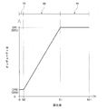
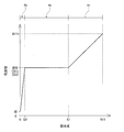
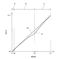
- FIG. 1 is an overall view of a light source device according to an embodiment, and is a control block diagram. It is a figure explaining control of the light modulation apparatus which concerns on the same embodiment, Comprising: It is a figure which shows the relationship of on-duty ratio with respect to a light control value. It is a figure explaining control of the light modulation apparatus which concerns on the same embodiment, Comprising: It is a figure which shows the relationship of the electric current value with respect to the light control value. It is a figure explaining the characteristic of the laser light source concerning the embodiment, Comprising: It is a figure which shows the relationship of the optical output with respect to an electric current value.
- the light source device 1 includes a laser light source 2 that emits laser light, and an input device 3 that inputs information on a dimming value for dimming the laser light source 2. Yes.
- the light source device 1 includes a light control device 4 that controls the brightness of the laser light source 2 based on the light control value input to the input device 3.
- the laser light source 2 includes at least one semiconductor laser that emits laser light.
- the semiconductor laser may be a CAN type having one emitter, an array type having a plurality of emitters, or an external resonator type semiconductor laser.
- the light source device 1 is used for, for example, a projection device (a projector or the like), an illumination device (a fiber illumination device, a spot illumination device, or the like).
- the input device 3 includes an operation unit 3a operated by the user in order for the user to input a desired dimming value.
- the operation unit 3a is a slide switch.
- the operation unit 3a is not limited to such a configuration, and may be a rotary switch, a numeric key switch, or the like.
- the input device 3 detects, for example, the switch position of the operation unit 3a as an analog voltage value, converts the analog voltage value into digital data, and then adjusts the light to the light control device 4 by serial communication such as DMX communication. Send value data.
- the input device 3 continuously transmits the dimming value to the dimming device 4 at a predetermined cycle regardless of whether or not the operation unit 3a is operated.
- the input device 3 may be configured to transmit data of the light control value to the light control device 4 when the light control value is changed by operating the operation unit 3a.
- the light control value is data of the number of bits corresponding to the number of gradations (light control value change amount) of the laser light source 2.
- the dimming value is 8-bit data when the gradation of the laser light source 2 is 256 gradations, and is 9 bits when the gradation of the laser light source 2 is 512 gradations. It becomes the data of.
- the light control device 4 includes an input unit 5 that receives the light control value transmitted from the input device 3 and inputs it as an input value, and a storage unit 6 that stores various data. In addition, the light control device 4 controls the direct current power supplied to the laser light source 2 based on the light control value input to the input unit 5 in order to control the brightness of the laser light source 2; And an output unit 8 that outputs electric power toward the laser light source 2.
- the control unit 7 controls the power supplied to the laser light source 2 and the dimming value is in the first dimming value region. And a second power control unit 7b for controlling the power supplied to the laser light source 2 when the value of the second dimming value region is darker.
- the control unit 7 also includes a third power control unit 7c that controls the power supplied to the laser light source 2 when the dimming value is a value in the third dimming value region that is darker than the second dimming value region. I have.
- the configuration of the light source device 1 according to the present embodiment is as described above. Next, a control method of the light control device 4 according to the present embodiment will be described with reference to FIGS.
- the gradation of the laser light source 2 is 512 gradations, the maximum dimming value is “511”, and the minimum dimming value is , “0”. And the larger the numerical value of the light control value, the brighter the laser light source 2 is.
- the information on the relationship between the light control value and the on-duty ratio according to FIG. 2 and the information on the relationship between the light control value and the current value according to FIG. 3 are stored in the storage unit 6.
- the dimming value in the first dimming value region R1 ranges from the maximum value “511” to the first set value “S1” (for example, 40% to 80% of the maximum value “511”).
- the dimming value in the light value region R2 is in a range from the first set value “S1” to the second set value “S2” (for example, 3% to 10% of the maximum value “511”).
- the dimming of the value region R3 is a range from the second set value “S2” to the minimum value “0”.
- the first and second set values S1 and S2 are stored in the storage unit 6 and may be set as default values or may be changed by being input through the input device 3, for example.
- the first power control unit 7a is configured to output a laser light source based on the dimming value.
- the current value supplied to 2 is controlled.
- the dimming value and the current value are in a proportional relationship.
- the current value is “I511” (for example, the laser light source 2
- the rated current is 70% to 100%).
- the dimming value is the darkest value in the first dimming value region R1 (that is, the minimum value and the first set value “S1”)
- the current value is “IS1” (for example, 30% to 80% of the rated current of the laser light source 2).
- the second power control unit 7b When the dimming value input to the input unit 5 is the value of the second dimming value region R2, the second power control unit 7b is turned on to supply power to the laser light source 2 based on the dimming value.
- the ratio between the time and the off time when supply is stopped, that is, the on-duty ratio is controlled.
- the dimming value and the on-duty ratio are in a proportional relationship.
- the on-duty ratio is “DS1”.
- the on-duty ratio “DS1” when the dimming value is the brightest value in the second dimming value region R2 is the on-duty ratio “DS1” when the dimming value is the value of the first dimming value region R1.
- DR1 ".
- the on-duty ratio is “DS2” (for example, 5% to 15%).
- the on-duty ratio “DS2” when the dimming value is the darkest value (that is, the minimum value and the second set value “S2”) in the second dimming region R2 is the human eye. It is determined by the PWM frequency (approximately 100 Hz or more) that does not feel flickering or the like, and the on-time that can be realized by the turn-on time, turn-off time, and time constant of the switching element of the output unit 8.
- the second power control unit 7b sets the current value supplied to the laser light source 2 to a constant value “IR2”. That is, in the control of the second power control unit 7b, the current value supplied to the laser light source 2 is constant regardless of the dimming value.
- the current value “IR2” when the dimming value is the value of the second dimming value region R2 is the current value “IR2” when the dimming value is the darkest value of the first dimming value region R1. It is the same as “IS1”.
- the third power control unit 7c determines the current value supplied to the laser light source 2 based on the dimming value. I have control. In the control of the third power control unit 7c, the dimming value and the current value are in a proportional relationship.
- the current value is “IS2”.
- the current value “IS2” when the dimming value is the brightest value in the third dimming value region R3 is the current value “IR2” when the dimming value is the value in the second dimming value region R2. The same.
- the current value is “I0” (for example, laser 5% to 30% of the rated current of the light source 2).
- the laser light source 2 emits light even when the dimming value is the darkest value in the third dimming value region R3.
- the third power control unit 7 c sets the ratio between the on time for supplying power to the laser light source 2 and the off time for stopping the supply, that is, the on duty ratio as a constant value “DR3”. Yes. That is, in the control of the third power control unit 7c, the on-duty ratio of the power supplied to the laser light source 2 is constant regardless of the dimming value.
- the on-duty ratio “DR3” when the dimming value is the value in the third dimming value region R3 is the on-duty ratio “DR3” when the dimming value is the darkest value in the second dimming value region R2.
- DS2 is the same.
- the laser light source 2 is a light source that emits laser light. Therefore, as shown in FIG. 4, the laser light source 2 emits light by dielectric emission (also referred to as “laser emission”) when the supplied current is equal to or greater than the threshold current value It (dielectric emission region), and the threshold current When it is less than the value It (spontaneous emission region), it emits light by spontaneous emission (also referred to as “LED emission”).
- dielectric emission also referred to as “laser emission”
- It spontaneous emission
- the current value supplied to the laser light source 2 is the value of the dielectric emission region and the current value supplied to the laser light source 2 is the value of the spontaneous emission region
- the current value and the optical output are Proportional relationship.
- the change in light output with respect to the current value in the stimulated emission region is larger than the change in light output with respect to the current value in the spontaneous emission region. Therefore, the current value and the light output in the laser light source 2 are not a simple proportional relationship (a relationship in which the relationship between the current value and the light output is linear over the entire area) as in a light source such as an LED.
- the third power control unit 7 c is configured such that when the dimming value is the darkest value in the third dimming value region R3 (that is, the dimming value “0”), A current value such that the laser light source 2 emits light by spontaneous emission is supplied to the laser light source 2. That is, the current value “I0” when the light control value is “0” is a current value smaller than the threshold current value It.
- the third power control unit 7c causes the laser light source 2 to emit light by stimulated emission when the dimming value is the brightest value in the third dimming value region R3 (that is, the second set value “S2”).
- a current value is supplied to the laser light source 2. That is, the current value “IS2” when the dimming value is the second set value “S2” is a current value larger than the threshold current value It.
- a solid line A1 indicates dimming that can be realized by control of the dimming device 4 according to the present embodiment.
- An alternate long and short dash line A0 indicates ideal light control with linearity (light control in which the relationship between the light control value and the light output is linear over the entire area).
- the first power control unit 7a controls the current value supplied to the laser light source 2 based on the dimming value.
- the light control of the laser light source 2 can be performed with a high on-duty ratio. Therefore, as compared with the case where the on-duty ratio is controlled, it is possible to suppress flickering (brightness / darkness) of light that is not felt by human eyes but appears in image data of a camera or the like having a short scan time.
- the current value and the light output in the laser light source 2 are not in a simple proportional relationship as in a light source such as an LED (see FIG. 4). Therefore, as shown in FIG. 5, in the first dimming value region R1, as the dimming value decreases, the difference between the light output of the actual dimming A1 and the light output of the ideal dimming A0 increases. Become.
- the second power control unit 7b controls the on-duty ratio of the power supplied to the laser light source 2.
- region R2 the difference between the light output of actual light control A1 and the light output of ideal light control A0 becomes small as a light control value becomes small. Therefore, light control close to ideal light control A0, that is, light control with linearity can be realized from the first light control value region R1 to the second light control value region R2.
- the third power control unit 7c controls the current value supplied to the laser light source 2 based on the dimming value. Therefore, even if the light control value is 3rd light control value area
- the solid line A11 and the two-dot chain line A12 both indicate the relationship of the light output with respect to the current value in the laser light sources 2 and 2.
- the relationship indicated by the solid line A11 and the two-dot chain line A12 has a slightly different individual difference.
- the individual error is caused by a manufacturing error. Occurs when it exists.
- the threshold current value “ A current value “I 0” smaller than “It (It 11, It 12)” is supplied to the laser light source 2. That is, when the dimming value is “0”, the current value “I0” in the spontaneous emission region is supplied to the laser light source 2.
- the change in light output with respect to the current value in the spontaneous emission region is smaller than the change in light output with respect to the current value in the stimulated emission region. Accordingly, the difference “ ⁇ P0” in the light output between the laser light sources 2 and 2 when the current value “I0” in the spontaneous emission region is supplied to the laser light source 2 indicates that the current value “I0a” in the stimulated emission region is the laser light source 2. Is smaller than the difference “ ⁇ P0a” in the light output between the laser light sources 2 and 2 when supplied to the laser beam. As a result, the light output at the darkest dimming value “0” in the third dimming value region R3 can be stabilized.
- the dimming value is the brightest value in the third dimming value region R3 (that is, the dimming value is the second set value “S2”).
- the current value “IS2” in the stimulated emission region is supplied to the laser light source 2 (see FIGS. 3 and 4).
- the change in light output with respect to the current value in the stimulated emission region is larger than the change in light output with respect to the current value in the spontaneous emission region.
- the light source device 1 includes the laser light source 2 that emits laser light, and the light control device 4 that controls the power supplied to the laser light source 2 based on the input light control value. Prepare.
- the light control apparatus 4 which concerns on this embodiment controls the electric power supplied to the said laser light source 2 based on the input light control value, in order to control the brightness of the laser light source 2 which emits a laser beam.
- the control unit 7 controls a power value supplied to the laser light source 2 based on the light control value.
- the laser light source is based on the light control value.
- the power value supplied to the laser light source 2 is controlled based on the dimming value. That comprises a third power control unit 7c, a.
- the first power control unit 7a uses the power of the power supplied to the laser light source 2 based on the dimming value. The value is controlled. Thereby, compared with the case where on-duty ratio is controlled, the flicker of the light by the laser light source 2 can be suppressed reliably in 1st light control value area
- the second power control unit 7b applies the laser light source 2 based on the dimming value.
- the ratio of the on time for supplying power and the off time for stopping the supply is controlled. Thereby, light control with linearity can be realized from the first light control value region R1 to the second light control value region R2.
- the third power control unit 7c applies the laser light source 2 to the laser light source 2 based on the dimming value.
- the power value of the supplied power is controlled. Therefore, it is possible to dim the laser light source 2 even in the third dimming value region R3. Therefore, wide light control can be realized
- the third power control unit 7c causes the laser to emit light when the dimming value is the darkest value “0” in the third dimming value region R3.
- a power value such that the light source 2 emits light by spontaneous emission is supplied to the laser light source 2.
- the third power control unit 7c supplies a predetermined power value, whereby the laser light source 2 Emits light by spontaneous emission.
- the change in light output with respect to the supplied power value is small.
- the third power control unit 7c causes the laser when the dimming value is the brightest value “S2” in the third dimming value region R3.
- a power value such that the light source 2 emits light by stimulated emission is supplied to the laser light source 2.
- the third power control unit 7c supplies a predetermined power value, whereby the laser light source 2 Emits light by stimulated emission.
- the change in the light output with respect to the supplied power value is large.
- the light control device and the light source device are not limited to the configuration of the above-described embodiment, and are not limited to the above-described effects.
- the light control device and the light source device can be variously modified without departing from the gist of the present invention.
- configurations, methods, and the like according to various modifications described below may be arbitrarily selected and employed in the configurations, methods, and the like according to the above-described embodiments.
- the light control device 4 uses a power value (specifically, a current value) such that the laser light source 2 emits light when the light control value is the darkest value “0”. It is the structure of supplying to.
- the light control device is not limited to such a configuration.
- the light control device may be configured such that power is not supplied to the laser light source 2 when the light control value is the darkest value “0”. In such a configuration, the darkest dimming value in the third dimming value region R3 is not “0” but the darkest dimming value among the dimming values emitted by the laser light source 2.
- the 1st electric power control part 7a is the structure of controlling an electric power value indirectly by controlling the electric current value supplied to the laser light source 2.
- the light control device is not limited to such a configuration.
- the first power control unit 7 a may be configured to indirectly control the power value by controlling the voltage value supplied to the laser light source 2.
- a configuration in which the power value to be supplied is directly controlled may be employed.
- the 3rd electric power control part 7c is the structure of controlling an electric power value indirectly by controlling the electric current value supplied to the laser light source 2.
- the light control device is not limited to such a configuration.
- the third power control unit 7 c may be configured to indirectly control the power value by controlling the voltage value supplied to the laser light source 2.
- a configuration in which the power value to be supplied is directly controlled may be employed.
- the third power control unit 7c is configured such that the laser light source 2 is natural when the dimming value is the darkest value “0” in the third dimming value region R3.
- a power value that emits light by emission (specifically, a current value “I0”) is supplied to the laser light source 2.
- the light control device is not limited to such a configuration.
- the third power control unit 7c sets a power value such that the laser light source 2 emits light by stimulated emission when the light control value is the darkest value in the third light control value region R3.
- the laser light source 2 may be supplied.
- the third power control unit 7c guides the laser light source 2 when the dimming value is the brightest value “S2” in the third dimming value region R3.
- a power value that emits light by emission (specifically, a current value “IS2”) is supplied to the laser light source 2.
- the light control device is not limited to such a configuration.
- the third power control unit 7c sets a power value such that the laser light source 2 emits light by spontaneous emission when the light control value is the brightest value in the third light control value region R3.
- the laser light source 2 may be supplied.
- the light control device 4 is configured separately from the input device 3 and receives light control value data from the input device 3 through communication.
- the light control device is not limited to such a configuration.
- the dimming device may be integrated with the input device 3 and may be configured such that the dimming value is input as an input value to the input unit 5 without going through communication by an operation on the operation unit 3a. .
- the output unit 8 is configured to output power toward the laser light source 2.
- the light control device is not limited to such a configuration.
- the output unit 8 may be configured to output an output value (data) toward the laser light source 2.
- the laser light source 2 may control the supplied power based on the output value output from the output unit 8.
Landscapes
- Physics & Mathematics (AREA)
- Condensed Matter Physics & Semiconductors (AREA)
- General Physics & Mathematics (AREA)
- Electromagnetism (AREA)
- Optics & Photonics (AREA)
- Circuit Arrangement For Electric Light Sources In General (AREA)
- Semiconductor Lasers (AREA)
Abstract
光源装置は、レーザ光を発するレーザ光源と、レーザ光源に供給する電力を制御する調光装置とを備える。調光装置は、調光値が第1調光値領域の値である際に、当該調光値に基づいて、レーザ光源に供給する電力値を制御する第1電力制御部と、調光値が第1調光値領域よりも暗い第2調光値領域の値である際に、当該調光値に基づいて、レーザ光源に電力を供給するオン時間と供給を停止するオフ時間との比を制御する第2電力制御部と、調光値が第2調光値領域よりも暗い第3調光値領域の値である際に、当該調光値に基づいて、レーザ光源に供給する電力値を制御する第3電力制御部と、を備える。
Description
本発明は、レーザ光源に供給する電力を制御する調光装置と、該調光装置を備える光源装置に関する。
従来、調光装置として、入力される調光値に基づいて、LEDや有機EL等の光源に供給する電力を制御する調光装置が、知られている(例えば、特許文献1)。該調光装置は、入力される調光値が最も明るい領域の値である際に、光源に供給する電流値を制御し、入力される調光値が次に明るい領域の値である際に、光源に電力を供給するオン時間と供給を停止するオフ時間との比を制御している。
なお、入力される調光値が最も暗い領域の値である際には、光源は、発光しない、又は、殆ど発光しない。したがって、入力される調光値が最も暗い領域の値である際には、光源の調光の要望が無かった。それにより、調光装置も、入力される調光値が最も暗い領域の値である際には、光源の調光を実施していなかった。
ところで、最近、光源として、レーザ光を発するレーザ光源が、知られている。該レーザ光源は、LEDや有機ELの光源よりも高出力であるため、入力される調光値が最も暗い領域の値である際でも、充分に発光する。したがって、幅広い調光を実現するために、レーザ光を発するレーザ光源に対しては、入力される調光値が最も暗い領域の値であっても、調光の要望がある。
よって、本発明は、斯かる事情に鑑み、幅広い調光を実現することができる調光装置及び光源装置を提供することを課題とする。
調光装置は、レーザ光を発するレーザ光源の明るさを制御するために、入力される調光値に基づいて、前記レーザ光源に供給する電力を制御する制御部を備え、前記制御部は、前記調光値が第1調光値領域の値である際に、当該調光値に基づいて、前記レーザ光源に供給する電力値を制御する第1電力制御部と、前記調光値が前記第1調光値領域よりも暗い第2調光値領域の値である際に、当該調光値に基づいて、前記レーザ光源に電力を供給するオン時間と供給を停止するオフ時間との比を制御する第2電力制御部と、前記調光値が前記第2調光値領域よりも暗い第3調光値領域の値である際に、当該調光値に基づいて、前記レーザ光源に供給する電力値を制御する第3電力制御部と、を備える。
また、調光装置においては、前記第3電力制御部は、前記調光値が前記第3調光値領域における最も暗い値である際に、前記レーザ光源が自然放出により発光するような電力値を、前記レーザ光源に供給する、という構成でもよい。
また、調光装置においては、前記第3電力制御部は、前記調光値が前記第3調光値領域における最も明るい値である際に、前記レーザ光源が誘導放出により発光するような電力値を、前記レーザ光源に供給する、という構成でもよい。
また、光源装置は、レーザ光を発するレーザ光源と、入力される調光値に基づいて、前記レーザ光源に供給する電力を制御する前記調光装置と、を備える。
以上の如く、本発明に係る調光装置及び光源装置は、幅広い調光を実現することができる、という優れた効果を奏する。
以下、調光装置及び光源装置における一実施形態について、図1~図6を参酌して説明する。
図1に示すように、本実施形態に係る光源装置1は、レーザ光を発するレーザ光源2と、レーザ光源2を調光するために調光値の情報を入力する入力装置3とを備えている。そして、光源装置1は、入力装置3に入力される調光値に基づいて、レーザ光源2の明るさを制御する調光装置4を備えている。
レーザ光源2は、レーザ光を発する少なくとも一つの半導体レーザを備えている。該半導体レーザは、1つのエミッタを有するCANタイプでもよく、複数のエミッタを有するアレイタイプでもよく、また、外部共振器型半導体レーザであってもよい。そして、光源装置1は、例えば、投影装置(プロジェクタ等)、照明装置(ファイバ照明装置、スポット照明装置等)等に用いられる。
入力装置3は、ユーザが所望の調光値を入力するために、ユーザに操作される操作部3aを備えている。本実施形態においては、操作部3aは、スライドスイッチとしているが、斯かる構成に限られず、例えば、回転スイッチ、テンキースイッチ等でもよい。そして、入力装置3は、例えば、操作部3aのスイッチ位置をアナログ電圧値として検出し、当該アナログ電圧値をデジタルデータに変換した後、DMX通信等のシリアル通信にて調光装置4に調光値のデータを送信する。
なお、入力装置3は、操作部3aの操作の有無に関わらず、調光値を、所定の周期で連続的に調光装置4へ送信している。そして、調光値は、通信周波数に応じた周期で、入力装置3から調光装置4に連続的に送信される。例えば、調光値は、通信周波数が44Hzである場合には、22.7ms(=1/44Hz)ごとに、入力装置3から調光装置4に送信される。なお、入力装置3は、操作部3aが操作されて調光値が変更された際に、調光値のデータを調光装置4へ送信する、という構成でもよい。
また、調光値は、レーザ光源2の階調(調光値変化量)の数に応じたビット数のデータである。例えば、調光値は、レーザ光源2の階調が256階調である場合には、8ビットのデータであり、また、レーザ光源2の階調が512階調である場合には、9ビットのデータとなる。
調光装置4は、入力装置3から送信された調光値を受信して入力値として入力される入力部5と、各種データを記憶する記憶部6とを備えている。また、調光装置4は、レーザ光源2の明るさを制御するために、入力部5に入力される調光値に基づいて、レーザ光源2に供給する直流電力を制御する制御部7と、レーザ光源2に向けて電力を出力する出力部8とを備えている。
制御部7は、調光値が第1調光値領域の値である際に、レーザ光源2に供給する電力を制御する第1電力制御部7aと、調光値が第1調光値領域よりも暗い第2調光値領域の値である際に、レーザ光源2に供給する電力を制御する第2電力制御部7bとを備えている。また、制御部7は、調光値が第2調光値領域よりも暗い第3調光値領域の値である際に、レーザ光源2に供給する電力を制御する第3電力制御部7cを備えている。
本実施形態に係る光源装置1の構成については以上の通りであり、次に、本実施形態に係る調光装置4の制御方法について、図2及び図3を参酌して説明する。
図2及び図3に示すように、本実施形態においては、レーザ光源2の階調は、512階調とし、調光値の最大値は、「511」であり、調光値の最小値は、「0」である。そして、調光値の数値が大きいほど、レーザ光源2が明るいことを示している。なお、図2に係る調光値とオンデューティ比との関係の情報、及び、図3に係る調光値と電流値との関係の情報は、記憶部6に記憶されている。
第1調光値領域R1の調光値は、最大値「511」から第1設定値「S1」(例えば、最大値「511」の40%~80%)までの範囲であり、第2調光値領域R2の調光値は、第1設定値「S1」から第2設定値「S2」(例えば、最大値「511」の3%~10%)までの範囲であり、第3調光値領域R3の調光は、第2設定値「S2」から最小値「0」までの範囲である。なお、第1及び第2設定値S1,S2は、記憶部6に記憶されており、既定値としてもよく、また、例えば、入力装置3で入力されることで変更可能であってもよい。
第1電力制御部7aは、図3に示すように、入力部5に入力される調光値が第1調光値領域R1の値である際に、当該調光値に基づいて、レーザ光源2に供給する電流値を制御している。第1電力制御部7aの制御においては、調光値と電流値とは、比例関係である。
例えば、調光値が第1調光値領域R1における最も明るい値(即ち、最大値であって、調光値「511」)の際に、電流値は、「I511」(例えば、レーザ光源2の定格電流の70%~100%)である。そして、例えば、調光値が第1調光値領域R1における最も暗い値(即ち、最小値であって、第1設定値「S1」)の際に、電流値は、「IS1」(例えば、レーザ光源2の定格電流の30%~80%)である。
また、第1電力制御部7aは、図2に示すように、レーザ光源2に電力を供給するオン時間と供給を停止するオフ時間との比、即ち、オンデューティ比(=オン時間/(オン時間+オフ時間))を一定値「DR1」(例えば、90%~100%)としている。即ち、第1電力制御部7aの制御においては、調光値に関わらず、レーザ光源2に供給する電力のオンデューティ比は、一定である。
第2電力制御7b部は、入力部5に入力される調光値が第2調光値領域R2の値である際に、当該調光値に基づいて、レーザ光源2に電力を供給するオン時間と供給を停止するオフ時間との比、即ち、オンデューティ比を制御している。第2電力制御部7bの制御においては、調光値とオンデューティ比とは、比例関係である。
例えば、調光値が第2調光値領域R2における最も明るい値(即ち、最大値であって、第1設定値「S1」)の際に、オンデューティ比は、「DS1」である。なお、調光値が第2調光値領域R2における最も明るい値である際のオンデューティ比「DS1」は、調光値が第1調光値領域R1の値である際のオンデューティ比「DR1」と同じである。
また、例えば、調光値が第2設定値「S2」の際に、オンデューティ比は、「DS2」(例えば、5%~15%)である。なお、調光値が第2調光領域R2における最も暗い値(即ち、最小値であって、第2設定値「S2」)である際の、オンデューティ比「DS2」は、人間の目でちらつきなどを感じないPWM周波数(概ね100Hz以上)で、出力部8のスイッチング素子のターンオン時間、ターンオフ時間や時定数で実現可能なオン時間で決定される。
また、第2電力制御部7bは、図3に示すように、レーザ光源2に供給する電流値を一定値「IR2」としている。即ち、第2電力制御部7bの制御においては、調光値に関わらず、レーザ光源2に供給する電流値は、一定である。なお、調光値が第2調光値領域R2の値である際の電流値「IR2」は、調光値が第1調光値領域R1の値の最も暗い値である際の電流値「IS1」と同じである。
第3電力制御部7cは、入力部5に入力される調光値が第3調光値領域R3の値である際に、当該調光値に基づいて、レーザ光源2に供給する電流値を制御している。第3電力制御部7cの制御においては、調光値と電流値とは、比例関係である。
例えば、調光値が第3調光値領域R3における最も明るい値(即ち、最大値であって、第2設定値「S2」)の際に、電流値は、「IS2」である。なお、調光値が第3調光値領域R3における最も明るい値の際の電流値「IS2」は、調光値が第2調光値領域R2の値である際の電流値「IR2」と同じである。
また、例えば、調光値が第3調光値領域R3における最も暗い値(即ち、最小値であって、調光値「0」)の際に、電流値は、「I0」(例えば、レーザ光源2の定格電流の5%~30%)である。本実施形態においては、調光値が第3調光値領域R3における最も暗い値である際も、レーザ光源2は、発光している。
また、第3電力制御部7cは、図2に示すように、レーザ光源2に電力を供給するオン時間と供給を停止するオフ時間との比、即ち、オンデューティ比を一定値「DR3」としている。即ち、第3電力制御部7cの制御においては、調光値に関わらず、レーザ光源2に供給する電力のオンデューティ比は、一定である。なお、調光値が第3調光値領域R3の値である際のオンデューティ比「DR3」は、調光値が第2調光値領域R2の最も暗い値である際のオンデューティ比「DS2」と同じである。
次に、調光値が第3調光値領域R3の値である際に、レーザ光源2に供給する電流値について、図3及び図4を参酌して説明する。
まず、レーザ光源2は、レーザ光を発する光源である。したがって、レーザ光源2は、図4に示すように、供給される電流が閾値電流値It以上(誘電放出領域)である際に、誘電放出により発光(「レーザ発光」ともいう)し、閾値電流値It未満(自然放出領域)である際に、自然放出により発光(「LED発光」ともいう)する。
そして、レーザ光源2に供給される電流値が誘電放出領域の値である際も、レーザ光源2に供給される電流値が自然放出領域の値である際も、電流値と光出力とは、比例関係である。しかしながら、誘導放出領域における電流値に対する光出力の変化は、自然放出領域における電流値に対する光出力の変化よりも、大きい。したがって、レーザ光源2における電流値と光出力とは、LED等の光源のような単純な比例関係(電流値と光出力との関係が全域に亘って一直線状となる関係)ではない。
そこで、図3及び図4に示すように、第3電力制御部7cは、調光値が第3調光値領域R3における最も暗い値(即ち、調光値「0」)である際に、レーザ光源2が自然放出により発光するような電流値を、レーザ光源2に供給する。即ち、調光値「0」である際の電流値「I0」は、閾値電流値Itより小さい電流値である。
また、第3電力制御部7cは、調光値が第3調光値領域R3における最も明るい値(即ち、第2設定値「S2」)である際に、レーザ光源2が誘導放出により発光するような電流値を、レーザ光源2に供給する。即ち、調光値が第2設定値「S2」である際の電流値「IS2」は、閾値電流値Itより大きい電流値である。
次に、本実施形態に係る調光装置4の制御による効果について、図5を参酌して説明する。
図5において、実線A1は、本実施形態に係る調光装置4の制御により実現できる調光を示している。なお、1点鎖線A0は、リニアリティのある理想的な調光(調光値と光出力との関係が全域に亘って一直線状となるような調光)を示している。
まず、調光値が第1調光値領域R1の値である際に、第1電力制御部7aは、当該調光値に基づいて、レーザ光源2に供給する電流値を制御している。これにより、高いオンデューティ比でレーザ光源2の調光を行うことができる。したがって、オンデューティ比を制御する場合と比較して、人間の目で感じないものの、スキャンタイムが短いカメラ等での撮像データで現れるような光のちらつき(明暗)も、抑制することができる。
ところで、レーザ光源2における電流値と光出力とが、LED等の光源のような単純な比例関係ではない(図4参照)。したがって、図5に示すように、第1調光値領域R1において、調光値が小さくなるにつれて、実際の調光A1の光出力と理想的な調光A0の光出力との差が、大きくなる。
そこで、調光値が第2調光値領域R2の値である際に、第2電力制御部7bは、レーザ光源2に供給する電力のオンデューティ比を制御している。これにより、第2調光値領域R2において、調光値が小さくなるにつれて、実際の調光A1の光出力と理想的な調光A0の光出力との差が、小さくなる。したがって、第1調光値領域R1から第2調光値領域R2にかけて、理想的な調光A0に近い調光、即ち、リニアリティのある調光を実現することができる。
そして、調光値が第3調光値領域R3の値である際に、第3電力制御部7cは、当該調光値に基づいて、レーザ光源2に供給する電流値を制御している。これにより、調光値が第3調光値領域R3であっても、レーザ光源2に対して調光することができている。したがって、幅広い調光を実現することができている。
次に、本実施形態に係る調光装置4の第3電力制御部7cの制御による効果について、図6を参酌して説明する。
図6において、実線A11と2点鎖線A12は、双方ともレーザ光源2,2における電流値に対する光出力の関係を示している。斯かる実線A11と2点鎖線A12とで示す関係は、若干相違する個体差を有する関係であるが、この個体差は、例えば、同じ設計に基づいて製造されたレーザ光源2において、製造誤差が存在した場合に発生する。
そして、本実施形態に係る第3電力制御部7cにおいては、調光値が第3調光値領域R3における最も暗い値(即ち、調光値「0」)である際に、閾値電流値「It(It11,It12)」よりも小さい電流値「I0」を、レーザ光源2に供給している。即ち、調光値が「0」である際に、自然放出領域の電流値「I0」を、レーザ光源2に供給している。
ところで、自然放出領域における電流値に対する光出力の変化は、誘導放出領域における電流値に対する光出力の変化よりも、小さい。したがって、自然放出領域の電流値「I0」をレーザ光源2に供給した際の、レーザ光源2,2間の光出力の相違「ΔP0」は、誘導放出領域の電流値「I0a」をレーザ光源2に供給した際の、レーザ光源2,2間の光出力の相違「ΔP0a」よりも、小さくなる。これにより、第3調光値領域R3における最も暗い調光値「0」における光出力を安定させることができる。
また、本実施形態に係る第3電力制御部7cにおいては、調光値が第3調光値領域R3における最も明るい値(即ち、調光値が第2設定値「S2」)である際に、誘導放出領域の電流値「IS2」を、レーザ光源2に供給している(図3及び図4参照)。そして、誘導放出領域における電流値に対する光出力の変化は、自然放出領域における電流値に対する光出力の変化よりも、大きい。
これにより、第3調光値領域R3においても、レーザ光源2の明暗の差が表れるため、調光を実現することができる。したがって、第3調光値領域R3においても、幅広い調光を実現することができる。
このように、第3調光値領域R3において、誘導放出領域の電流のみを用いる調光では、レーザ光源2の個体差により、最小の電流値「I0a」でも大きな光出力の相違「ΔP0a」が発生するのに対して、誘導放出領域の電流だけでなく、自然放出領域の電流を用いる調光では、最小の電流値「I0」では光出力の相違「ΔP0」が殆ど発生しないようにすることが可能となり、しかも、広い範囲での調光が可能となる。
以上より、本実施形態に係る光源装置1は、レーザ光を発するレーザ光源2と、入力される調光値に基づいて、前記レーザ光源2に供給する電力を制御する調光装置4と、を備える。
そして、本実施形態に係る調光装置4は、レーザ光を発するレーザ光源2の明るさを制御するために、入力される調光値に基づいて、前記レーザ光源2に供給する電力を制御する制御部7を備え、前記制御部7は、前記調光値が第1調光値領域R1の値である際に、当該調光値に基づいて、前記レーザ光源2に供給する電力値を制御する第1電力制御部7aと、前記調光値が前記第1調光値領域R1よりも暗い第2調光値領域R2の値である際に、当該調光値に基づいて、前記レーザ光源2に電力を供給するオン時間と供給を停止するオフ時間との比を制御する第2電力制御部7bと、前記調光値が前記第2調光値領域R2よりも暗い第3調光値領域R3の値である際に、当該調光値に基づいて、前記レーザ光源2に供給する電力値を制御する第3電力制御部7cと、を備える。
斯かる構成によれば、調光値が第1調光値領域R1の値である際に、第1電力制御部7aは、当該調光値に基づいて、レーザ光源2に供給する電力の電力値を制御している。これにより、オンデューティ比を制御する場合と比較して、第1調光値領域R1において、レーザ光源2による光のちらつきを確実に抑制することができる。
そして、調光値が第1調光値領域R1よりも暗い第2調光値領域R2の値である際に、第2電力制御部7bは、当該調光値に基づいて、レーザ光源2に電力を供給するオン時間と供給を停止するオフ時間との比を制御している。これにより、第1調光値領域R1から第2調光値領域R2に亘って、リニアリティのある調光を実現することができる。
さらに、調光値が第2調光値領域R2よりも暗い第3調光値領域R3の値である際に、第3電力制御部7cは、当該調光値に基づいて、レーザ光源2に供給する電力の電力値を制御している。これにより、第3調光値領域R3であっても、レーザ光源2に対して調光することができる。したがって、幅広い調光を実現することができる
また、本実施形態に係る調光装置4においては、前記第3電力制御部7cは、前記調光値が前記第3調光値領域R3における最も暗い値「0」である際に、前記レーザ光源2が自然放出により発光するような電力値を、前記レーザ光源2に供給する、という構成である。
斯かる構成によれば、調光値が第3調光値領域R3における最も暗い値「0」である際に、第3電力制御部7cが所定の電力値を供給することで、レーザ光源2は、自然放出により発光する。そして、レーザ光源2の自然放出の領域においては、供給する電力値に対する光出力の変化が小さい。これにより、例えば、レーザ光源2に供給する電力値に対する光出力に、個体差が存在していても、第3調光値領域R3における最も暗い調光値「0」における光出力を安定させることができる。
また、本実施形態に係る調光装置4においては、前記第3電力制御部7cは、前記調光値が前記第3調光値領域R3における最も明るい値「S2」である際に、前記レーザ光源2が誘導放出により発光するような電力値を、前記レーザ光源2に供給する、という構成である。
斯かる構成によれば、調光値が第3調光値領域R3における最も明るい値「S2」である際に、第3電力制御部7cが所定の電力値を供給することで、レーザ光源2は、誘導放出により発光する。そして、レーザ光源2の誘導放出の領域においては、供給する電力値に対する光出力の変化が大きい。これにより、第3調光値領域R3においても、十分に幅広い調光を実現することができる。
なお、調光装置及び光源装置は、上記した実施形態の構成に限定されるものではなく、また、上記した作用効果に限定されるものではない。また、調光装置及び光源装置は、本発明の要旨を逸脱しない範囲内において種々変更を加え得ることは勿論である。例えば、下記する各種の変更例に係る構成や方法等を任意に選択して、上記した実施形態に係る構成や方法等に採用してもよいことは勿論である。
上記実施形態に係る調光装置4は、調光値が最も暗い値「0」である際に、レーザ光源2が発光するような電力値(具体的には、電流値)を、レーザ光源2に供給する、という構成である。しかしながら、調光装置は、斯かる構成に限られない。例えば、調光装置は、調光値が最も暗い値「0」である際に、レーザ光源2に電力を供給しない、という構成でもよい。斯かる構成においては、第3調光値領域R3の最も暗い調光値は、「0」ではなく、レーザ光源2が発光する調光値のうち、最も暗い値となる。
また、上記実施形態に係る調光装置4においては、第1電力制御部7aは、レーザ光源2に供給する電流値を制御することで、間接的に電力値を制御する、という構成である。しかしながら、調光装置は、斯かる構成に限られない。例えば、調光装置においては、第1電力制御部7aは、レーザ光源2に供給する電圧値を制御することで、間接的に電力値を制御する、という構成でもよく、また、レーザ光源2に供給する電力値を直接的に制御する、という構成でもよい。
また、上記実施形態に係る調光装置4においては、第3電力制御部7cは、レーザ光源2に供給する電流値を制御することで、間接的に電力値を制御する、という構成である。しかしながら、調光装置は、斯かる構成に限られない。例えば、調光装置においては、第3電力制御部7cは、レーザ光源2に供給する電圧値を制御することで、間接的に電力値を制御する、という構成でもよく、また、レーザ光源2に供給する電力値を直接的に制御する、という構成でもよい。
また、上記実施形態に係る調光装置4においては、第3電力制御部7cは、調光値が第3調光値領域R3における最も暗い値「0」である際に、レーザ光源2が自然放出により発光するような電力値(具体的には、電流値「I0」)を、レーザ光源2に供給する、という構成である。しかしながら、調光装置は、斯かる構成に限られない。例えば、調光装置においては、第3電力制御部7cは、調光値が第3調光値領域R3における最も暗い値である際に、レーザ光源2が誘導放出により発光するような電力値を、レーザ光源2に供給する、という構成でもよい。
また、上記実施形態に係る調光装置4においては、第3電力制御部7cは、調光値が第3調光値領域R3における最も明るい値「S2」である際に、レーザ光源2が誘導放出により発光するような電力値(具体的には、電流値「IS2」)を、レーザ光源2に供給する、という構成である。しかしながら、調光装置は、斯かる構成に限られない。例えば、調光装置においては、第3電力制御部7cは、調光値が第3調光値領域R3における最も明るい値である際に、レーザ光源2が自然放出により発光するような電力値を、レーザ光源2に供給する、という構成でもよい。
また、上記実施形態に係る調光装置4は、入力装置3と別体であって、通信を経由することで、入力装置3から調光値のデータを受信する、という構成である。しかしながら、調光装置は、斯かる構成に限られない。例えば、調光装置は、入力装置3と一体であって、操作部3aでの操作により、通信を経由することなく、調光値が入力部5に入力値として入力される、という構成でもよい。
また、上記実施形態に係る調光装置4においては、出力部8は、レーザ光源2に向けて電力を出力する、という構成である。しかしながら、調光装置は、斯かる構成に限られない。例えば、調光装置においては、出力部8は、レーザ光源2に向けて出力値(データ)を出力する、という構成でもよい。そして、レーザ光源2は、出力部8から出力された出力値に基づいて、供給される電力を制御してもよい。
1…光源装置、2…レーザ光源、3…入力装置、3a…操作部、4…調光装置、5…入力部、6…記憶部、7…制御部、7a…第1電力制御部、7b…第2電力制御部、7c…第3電力制御部、8…出力部、R1…第1調光値領域、R2…第2調光値領域、R3…第3調光値領域
Claims (4)
- レーザ光を発するレーザ光源の明るさを制御するために、入力される調光値に基づいて、前記レーザ光源に供給する電力を制御する制御部を備え、
前記制御部は、
前記調光値が第1調光値領域の値である際に、当該調光値に基づいて、前記レーザ光源に供給する電力値を制御する第1電力制御部と、
前記調光値が前記第1調光値領域よりも暗い第2調光値領域の値である際に、当該調光値に基づいて、前記レーザ光源に電力を供給するオン時間と供給を停止するオフ時間との比を制御する第2電力制御部と、
前記調光値が前記第2調光値領域よりも暗い第3調光値領域の値である際に、当該調光値に基づいて、前記レーザ光源に供給する電力値を制御する第3電力制御部と、を備える調光装置。 - 前記第3電力制御部は、前記調光値が前記第3調光値領域における最も暗い値である際に、前記レーザ光源が自然放出により発光するような電力値を、前記レーザ光源に供給する請求項1に記載の調光装置。
- 前記第3電力制御部は、前記調光値が前記第3調光値領域における最も明るい値である際に、前記レーザ光源が誘導放出により発光するような電力値を、前記レーザ光源に供給する請求項2に記載の調光装置。
- レーザ光を発するレーザ光源と、
入力される調光値に基づいて、前記レーザ光源に供給する電力を制御する請求項1~3の何れか1項に記載の調光装置と、を備える光源装置。
Applications Claiming Priority (2)
| Application Number | Priority Date | Filing Date | Title |
|---|---|---|---|
| JP2015-073418 | 2015-03-31 | ||
| JP2015073418A JP6015799B1 (ja) | 2015-03-31 | 2015-03-31 | 調光装置及び光源装置 |
Publications (1)
| Publication Number | Publication Date |
|---|---|
| WO2016158035A1 true WO2016158035A1 (ja) | 2016-10-06 |
Family
ID=57004920
Family Applications (1)
| Application Number | Title | Priority Date | Filing Date |
|---|---|---|---|
| PCT/JP2016/054260 Ceased WO2016158035A1 (ja) | 2015-03-31 | 2016-02-15 | 調光装置及び光源装置 |
Country Status (2)
| Country | Link |
|---|---|
| JP (1) | JP6015799B1 (ja) |
| WO (1) | WO2016158035A1 (ja) |
Cited By (1)
| Publication number | Priority date | Publication date | Assignee | Title |
|---|---|---|---|---|
| US11223184B2 (en) * | 2017-09-06 | 2022-01-11 | Ricoh Electronic Devices Co., Ltd. | Semiconductor laser driver having electronic dimming function without using optical components |
Families Citing this family (2)
| Publication number | Priority date | Publication date | Assignee | Title |
|---|---|---|---|---|
| JP6564538B1 (ja) * | 2018-02-27 | 2019-08-21 | オリンパス株式会社 | 内視鏡用光源装置 |
| CN114650764B (zh) | 2019-11-13 | 2025-05-06 | 索尼奥林巴斯医疗解决方案公司 | 光源设备与被检体观察系统 |
Citations (2)
| Publication number | Priority date | Publication date | Assignee | Title |
|---|---|---|---|---|
| JP2013168585A (ja) * | 2012-02-16 | 2013-08-29 | Sharp Corp | 発光装置、半導体レーザ素子、車両用前照灯、および照明装置 |
| JP2014186972A (ja) * | 2013-03-25 | 2014-10-02 | Yamaha Corp | 制御信号生成装置及び音響信号処理装置 |
Family Cites Families (1)
| Publication number | Priority date | Publication date | Assignee | Title |
|---|---|---|---|---|
| JP2011165496A (ja) * | 2010-02-10 | 2011-08-25 | Panasonic Electric Works Co Ltd | 点灯装置 |
-
2015
- 2015-03-31 JP JP2015073418A patent/JP6015799B1/ja not_active Expired - Fee Related
-
2016
- 2016-02-15 WO PCT/JP2016/054260 patent/WO2016158035A1/ja not_active Ceased
Patent Citations (2)
| Publication number | Priority date | Publication date | Assignee | Title |
|---|---|---|---|---|
| JP2013168585A (ja) * | 2012-02-16 | 2013-08-29 | Sharp Corp | 発光装置、半導体レーザ素子、車両用前照灯、および照明装置 |
| JP2014186972A (ja) * | 2013-03-25 | 2014-10-02 | Yamaha Corp | 制御信号生成装置及び音響信号処理装置 |
Cited By (1)
| Publication number | Priority date | Publication date | Assignee | Title |
|---|---|---|---|---|
| US11223184B2 (en) * | 2017-09-06 | 2022-01-11 | Ricoh Electronic Devices Co., Ltd. | Semiconductor laser driver having electronic dimming function without using optical components |
Also Published As
| Publication number | Publication date |
|---|---|
| JP2016194981A (ja) | 2016-11-17 |
| JP6015799B1 (ja) | 2016-10-26 |
Similar Documents
| Publication | Publication Date | Title |
|---|---|---|
| CN101536607B (zh) | 用于确定驱动值以驱动照明装置的方法和驱动器 | |
| JP2008060222A (ja) | 発光素子駆動装置およびその方法 | |
| JP5299722B2 (ja) | Led照明装置 | |
| US11259377B2 (en) | Color temperature and intensity configurable lighting fixture using de-saturated color LEDs | |
| KR100628721B1 (ko) | 디스플레이장치 및 그 제어방법 | |
| CN109922572A (zh) | 一种μLED电流模式像素驱动电路系统 | |
| JP2014186972A (ja) | 制御信号生成装置及び音響信号処理装置 | |
| JP6015799B1 (ja) | 調光装置及び光源装置 | |
| US8664869B2 (en) | Method for controlling an electrical load | |
| KR100661661B1 (ko) | 디스플레이장치 및 그 제어방법 | |
| US9137875B2 (en) | Method for operating at least one light-emitting diode and lighting device for carrying out the method | |
| JP2013191522A (ja) | 照明装置 | |
| US10368415B2 (en) | Lighting apparatus | |
| CN114651529B (zh) | 布置为发射跟随颜色空间中的普朗克轨迹的特定发射光的基于发光二极管led的照明设备 | |
| JP2008171983A (ja) | 光源装置、画像表示装置、プロジェクタおよび光源制御方法 | |
| JP2010206085A (ja) | 発光装置、照明装置及び該照明装置の駆動方法 | |
| WO2023090058A1 (ja) | 照明装置、照明装置の駆動方法、車両用灯具 | |
| US20090026983A1 (en) | Lighting Device and Display System with a Lighting Device | |
| JPWO2012153594A1 (ja) | 照明装置 | |
| KR20180011036A (ko) | 조명 장치 | |
| JP6756804B2 (ja) | 光源駆動装置および照明システム | |
| JP2019053905A (ja) | 照明装置 | |
| JP2025102016A (ja) | 点灯装置及び照明装置 | |
| JP2024136986A (ja) | 点灯装置及び照明装置 | |
| JP2015088386A (ja) | Led駆動装置及び照明器具 |
Legal Events
| Date | Code | Title | Description |
|---|---|---|---|
| 121 | Ep: the epo has been informed by wipo that ep was designated in this application |
Ref document number: 16771919 Country of ref document: EP Kind code of ref document: A1 |
|
| NENP | Non-entry into the national phase |
Ref country code: DE |
|
| 122 | Ep: pct application non-entry in european phase |
Ref document number: 16771919 Country of ref document: EP Kind code of ref document: A1 |