WO2016157789A1 - 車両用空調設定装置 - Google Patents
車両用空調設定装置 Download PDFInfo
- Publication number
- WO2016157789A1 WO2016157789A1 PCT/JP2016/001531 JP2016001531W WO2016157789A1 WO 2016157789 A1 WO2016157789 A1 WO 2016157789A1 JP 2016001531 W JP2016001531 W JP 2016001531W WO 2016157789 A1 WO2016157789 A1 WO 2016157789A1
- Authority
- WO
- WIPO (PCT)
- Prior art keywords
- range
- wind
- wind range
- touch panel
- image
- Prior art date
- Legal status (The legal status is an assumption and is not a legal conclusion. Google has not performed a legal analysis and makes no representation as to the accuracy of the status listed.)
- Ceased
Links
Images










Classifications
-
- B—PERFORMING OPERATIONS; TRANSPORTING
- B60—VEHICLES IN GENERAL
- B60H—ARRANGEMENTS OF HEATING, COOLING, VENTILATING OR OTHER AIR-TREATING DEVICES SPECIALLY ADAPTED FOR PASSENGER OR GOODS SPACES OF VEHICLES
- B60H1/00—Heating, cooling or ventilating devices
-
- G—PHYSICS
- G06—COMPUTING OR CALCULATING; COUNTING
- G06F—ELECTRIC DIGITAL DATA PROCESSING
- G06F3/00—Input arrangements for transferring data to be processed into a form capable of being handled by the computer; Output arrangements for transferring data from processing unit to output unit, e.g. interface arrangements
- G06F3/01—Input arrangements or combined input and output arrangements for interaction between user and computer
- G06F3/03—Arrangements for converting the position or the displacement of a member into a coded form
- G06F3/041—Digitisers, e.g. for touch screens or touch pads, characterised by the transducing means
-
- G—PHYSICS
- G06—COMPUTING OR CALCULATING; COUNTING
- G06F—ELECTRIC DIGITAL DATA PROCESSING
- G06F3/00—Input arrangements for transferring data to be processed into a form capable of being handled by the computer; Output arrangements for transferring data from processing unit to output unit, e.g. interface arrangements
- G06F3/01—Input arrangements or combined input and output arrangements for interaction between user and computer
- G06F3/048—Interaction techniques based on graphical user interfaces [GUI]
- G06F3/0481—Interaction techniques based on graphical user interfaces [GUI] based on specific properties of the displayed interaction object or a metaphor-based environment, e.g. interaction with desktop elements like windows or icons, or assisted by a cursor's changing behaviour or appearance
Definitions
- FIG. 7 is a diagram illustrating a wind range designation image in which the position of the occupant image is different from that in FIG. 6.
- FIG. 8 is a diagram illustrating a wind range graphic corresponding to the wind range set by the tap operation.
- FIG. 9 is a diagram illustrating a state where an oblique operation, which is an example of a miss operation, is performed.
- FIG. 10 is a diagram showing a wind range graphic displayed on the display unit corresponding to the wind range set after the oblique operation of FIG. 9 is performed.
- FIG. 11 is a diagram illustrating a state where a face start point operation, which is an example of a miss operation, is performed.
- FIG. 12 is a diagram showing a wind range graphic 5 displayed on the display unit corresponding to the wind range set after the face start point operation of FIG. 11 is performed.
- FIG. 13 is a diagram illustrating a state in which a protrusion operation is performed, which is an example of a mistake operation.
- FIG. 14 is a diagram showing a wind range graphic displayed on the display unit corresponding to the wind range set after the protrusion operation of FIG. 13 is performed.
- FIG. 15 is a display example of the second embodiment, and is a display example when a drag operation is performed by multi-touch.
- FIG. 16 is a display example after the operation of FIG.
- FIG. 17 is a display example of the second embodiment, which is a display example immediately before a strong pressing operation is performed on the center portion of the wind range designation image.
- FIG. 18 shows a display example after the strong pressing operation is performed at the position of the index finger in FIG.
- FIG. 19 is a display example of the second embodiment, and is a display example immediately before the left end portion of the wind range designation image is strongly pressed.
- FIG. 20 is a display example after the strong pressing operation is performed at the position of the index finger in FIG.
- a vehicle air conditioning system 100 shown in FIG. 1 is mounted on a vehicle.
- the vehicle air conditioning system 100 includes a vehicle air conditioner (hereinafter referred to as an air conditioner) 1, a setting device 2, and a face position recognition device 3.
- a vehicle equipped with the vehicle air conditioning system 100 is referred to as a host vehicle.
- the vertical louver 14 is provided in the vicinity of the horizontal louver 12 on the upstream side of the air flow path from the air outlet or the air outlet.
- the vertical louver 14 includes a plurality of long plates formed so as to extend in the arrangement direction of the horizontal louvers 12.
- the plurality of long plates are arranged at intervals in the longitudinal direction of the long plate of the horizontal louver 12.
- Each long plate of the vertical louver 14 is disposed so as to be rotatable about a shaft extending in the longitudinal direction of the long plate.
- the horizontal direction of the wind blown from the air outlet located downstream of the vertical louver 14 and the concentrated diffusion degree of the wind are adjusted.
- the width in the left-right direction of the blown-out wind becomes narrower.
- the width of the blown-out wind in the left-right direction is increased.
- the direction of the horizontal louver 12 is controlled by the horizontal louver motor 13, so that the vertical direction of the wind blown from the air outlet located downstream of the horizontal louver 12 is adjusted.
- the explanation will be made assuming that the concentrated diffusion degree in the vertical direction of the wind blown from the outlet is not adjusted. However, you may make it adjust the concentrated diffusion degree of the up-down direction of the wind which blows off from a blower outlet. If the distance between adjacent long plates of the horizontal louver 12 becomes narrower toward the blowing direction, the vertical width of the blown-out wind can be reduced. On the contrary, if the distance between the adjacent long plates of the horizontal louver 12 is increased toward the blowing direction, the vertical width of the blown-out wind can be increased.
- the setting device 2 that is a vehicle air conditioning setting device includes a display ECU 21, a display unit 22, and a touch panel 23.
- the display unit 22 is capable of color display and can be configured using a liquid crystal display or the like.
- a touch panel 23 is overlaid on the display unit 22.
- the display unit 22 on which the touch panel 23 is superimposed is disposed at a position where the driver's hand seated in the driver's seat can reach.
- the display ECU 21 includes a CPU, a memory such as a ROM and a RAM, and the display ECU 21 executes a control program stored in the ROM while using a temporary storage function of the RAM. It functions as the setting unit 212.
- the display ECU 21 functions as the display control unit 211 and the air conditioning setting unit 212, but separate ECUs may function as the display control unit 211 and the air conditioning setting unit 212, respectively. Further, some or all of the functions executed by the display ECU 21 may be configured in hardware by one or a plurality of ICs.
- the display control unit 211 causes the display unit 22 to display various setting images for performing settings for the air conditioner 1.
- This setting image includes a wind range designation image 4 shown in FIG. Further, a screen showing the state of air conditioning performed by the air conditioner 1 is also displayed on the display unit 22.
- Settings for the air conditioner 1 include temperature setting, air outlet selection, and air volume setting. There is also a setting of the direction of the wind near the driver's seat and the concentration and diffusion degree of the wind, the setting of the direction of the wind near the passenger seat and the concentration and diffusion degree of the wind. Therefore, the air conditioning setting unit 212 corresponds to a wind range setting unit in the claims.
- the setting of the wind direction to the vicinity of the driver's seat and the concentrated diffusion degree of the wind is performed while the display control unit 211 displays the wind range designation image 4 on the display unit 22. Further, the setting of the direction of the wind near the passenger seat and the concentration and diffusion level of the wind is also performed in a state where the display control unit 211 displays the wind range designation image 4 on the display unit 22.
- the face position recognition device 3 determines the face position of the front seat occupant by analyzing a camera that captures the face of the front seat occupant (that is, the driver and the passenger in the passenger seat) and the vicinity thereof, and an image captured by the camera. It is a well-known structure provided with the control part which performs. The face position recognition device 3 sequentially outputs a signal representing the determined face position of the front seat occupant to the display control unit 211 of the display ECU 21.
- the operation for displaying the wind range designation image 4 can be performed on the driver seat and the passenger seat, respectively.
- the wind range near the driver seat can be set using the wind range designating image 4 for the driver seat
- the wind range near the passenger seat can be set using the wind range designating image 4 for the passenger seat.
- the method for setting the wind range near the driver's seat after the wind range specifying image 4 is displayed is the same as the method for setting the wind range near the passenger seat.
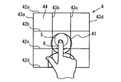
- the wind range designating image 4 of the present embodiment is square and includes an occupant image 41, grid horizontal lines 42, and grid vertical lines 43.
- the occupant image 41 is an image representing an occupant seated in the front seat.
- the occupant image 41 of the present embodiment is not an image obtained by actually photographing the front seat occupant but an image prepared in advance. However, an image obtained by actually photographing the driver or the passenger on the front passenger seat may be used as the passenger image 41.
- a plurality of grid horizontal lines 42 are displayed in the wind range designation image 4. Specifically, in FIG. 2, four grid horizontal lines 42a, 42b, 42c, and 42d are displayed. When the plurality of grid horizontal lines 42a, 42b, 42c, and 42d are not distinguished, they are simply referred to as grid horizontal lines 42.
- the four grid horizontal lines 42 all extend in the vehicle width direction, are parallel to each other, and are arranged at equal intervals. The interval between the grid horizontal lines 42 is longer than the contact length in the vertical direction of the fingertip with respect to the touch panel 23 when the touch panel 23 is touched with the fingertip, and is, for example, about twice the contact length.
- the start point is the lower left rectangular range 44
- the lower right rectangular range 44 is the end point
- the grid horizontal lines 42c and 42d are not crossed from the start point to the end point between the grid horizontal lines 42c and 42d. In this way, the index finger 6 moves.
- the wind range designation image 4 is associated with the range in which the front seat occupant is normally located. Specifically, the wind range designation image 4 when the driver's seat is designated corresponds to the range where the driver seated on the driver's seat is the position of the normal occupant image 41. The wind range designation image 4 when the passenger seat is designated corresponds to the range in which the occupant seated in the passenger seat is the position of the normal occupant image 41.
- the wind range graphic 5 superimposed on the wind range designating image 4 represents the range of wind blown out near the driver or passenger in the passenger seat.
- the wind range in the vertical direction is based on the range between the two grid horizontal lines 42.
- the wind range in the left-right direction is from the start point to the end point of the drag operation on the wind range designation image 4 regardless of the grid vertical line 43.
- the vertical direction of the wind blown from the outlet toward the front seat occupant is two as shown in FIG. 3 and FIG.
- the corresponding orientation is between the grid horizontal lines 42c and 42d.
- the horizontal direction and the degree of concentrated diffusion are the direction and the degree of diffusion corresponding to almost the entire horizontal range of the wind range designation image 4. Note that one or a plurality of outlets for blowing wind to the front seat occupant may be used.
- wind range graphic 5 and 6 are also display examples of the wind range graphic 5 after the drag operation is completed when the drag operation is a normal operation.
- the vertical direction of the wind blown from the outlet toward the front seat occupant corresponds between the two grid horizontal lines 42 a and 42 b. It becomes the direction.
- the horizontal direction and the concentration diffusion degree are the direction and the concentration diffusion degree from between the grid vertical lines 43a and 43b to between the grid vertical lines 43b and 43c.
- the wind range graphic 5 When the wind range graphic 5 is displayed at the position of FIG. 6, the wind blown out from the outlet toward the front seat occupant has the same vertical direction as FIG.
- the horizontal direction and the degree of concentrated diffusion are the direction and the degree of concentrated diffusion from between the grid vertical lines 43a and 43b to between the grid vertical lines 43c and 43d.
- the degree of concentrated diffusion is the same as that in FIG.
- the display position and size of the wind range graphic 5 are the same as those in FIG. 6, but the position of the occupant image 41 is different from that in FIG. 6.
- the reason why the position of the occupant image 41 in FIG. 7 is different from that in FIG. 6 is that the display control unit 211 changes the occupant image 41 in the wind range designation image 4 based on the signal input from the face position recognition device 3 This is because it is displayed at a position corresponding to the position of the front seat occupant.
- the display example of FIG. 8 is a display example of the wind range graphic 5 after the end of the tap operation when the tap operation is performed instead of the drag operation.
- the air conditioning setting unit 212 sets the minimum range determined based on the tap operation as the wind range.
- the horizontal range of the wind range is set regardless of the grid vertical line 43. Therefore, when a tap operation is performed, the range of the minimum length in the left-right direction including the position determined by the tap operation is set as the range in the left-right direction of the wind range.
- the minimum length in the left-right direction is determined based on the length in the left-right direction of the wind when the air conditioner 1 blows the most concentrated wind. Since the range of the wind in the vertical direction is based on the range sandwiched by the two grid horizontal lines 42, the range in the vertical direction of the wind range when the tap operation is performed is the two that sandwich the position where the tap operation is performed. Between the grid horizontal lines 42.
- the miss operation is a drag operation that designates a wind range that cannot be set by the air conditioner 1.
- the miss operation in the present embodiment is the following (1) to (3).
- this operation is referred to as an oblique operation.
- this operation is referred to as a face start point operation.
- this operation is referred to as a protrusion operation.
- the wind range is set based on a part of the drag operation range. For example, in the case of an oblique operation and not a face start point operation, the drag operation start point on the wind range designation image 4 is used as part of the drag operation range, and the range determined based on this drag operation start point is Range.
- FIG. 9 is an example in which the drag operation crosses the grid horizontal line 42c because the direction of the drag operation is diagonally downward to the right. As shown in FIG. 9, even if the drag operation is a miss operation, the wind range graphic 5 is updated and displayed as the index finger 6 moves while the drag operation is being performed.
- FIG. 10 shows a wind range designation image 4 in which a wind range graphic 5 displayed after the drag operation is completed from the state of FIG. 9 is superimposed.
- the wind range graphic 5 shown in FIG. 10 is displayed in a rectangular range 44 including the starting point of the drag operation.
- the length of the wind range graphic 5 in the vertical direction is the same as that of the normal wind range graphic 5, and the length in the left-right direction is a preset left-right length set at the time of a mistake operation.
- the wind direction in the vertical direction is between the grid horizontal lines 42b and 42c, and the wind direction in the horizontal direction is It is within the rectangular range 44 that includes the starting point of the drag operation. Further, the concentrated diffusion degree is the most concentrated state.
- FIG. 9 is also a protruding operation because the end point of the drag operation is located outside the wind range designation image 4.
- the treatment for the oblique operation is given priority over the treatment for the protrusion operation.
- a part or all of the right side of the occupant image 41 on the wind range designation image 4 in the drag operation range is set as the wind range. Then, the wind range graphic 5 corresponding to the wind range is superimposed and displayed on the wind range designating image 4.
- a part of the drag operation range on the right side of the occupant image 41 is, for example, a rectangular range 44 on the right side of the occupant image 41.
- the occupant image 41 may have moved from the center of the wind range designation image 4, and there may be no right portion of the drag operation range from the occupant image 41. In that case, the wind range is not set.
- the rectangular range 44 in the middle of the right end row is the rectangular range 44 closer to the end point of the drag operation range than the face position of the occupant image 41.
- the wind range graphic 5 is displayed in 44. A range corresponding to the wind range graphic 5 is set as the wind range.
- FIG. 11 is also an oblique operation because the drag operation crosses the grid horizontal line 42b.
- the treatment for the face position start point operation is given priority over the treatment for the oblique operation. Therefore, when the drag operation of FIG. 11 is performed, the wind range graphic 5 is displayed at the position shown in FIG. 12, and the range corresponding to the wind range graphic 5 displayed in FIG. 12 is set as the wind range.
- the air conditioning setting unit 212 sets the range on the wind range designation image 4 in the drag operation range as the wind range, and instructs the display control unit 211 to set the wind range graphic 5 corresponding to the wind range. Is superimposed on the wind range designation image 4.
- FIG. 13 is a display example during the drag operation when both the start point and the end point of the drag operation range are located outside the wind range designation image 4.
- FIG. 14 shows a wind range designation image 4 on which the wind range graphic 5 is displayed in a superimposed manner, which is displayed after the drag operation is completed from the state of FIG.
- the display control unit 211 displays the display on which the touch panel 23 is superimposed.
- the wind range designation image 4 is displayed on the unit 22.
- the air conditioning setting unit 212 wind direction and wind concentration diffusion based on the dragged range.
- the air conditioning setting unit 212 sets the minimum range determined based on the tap operation when the touch panel 23 is tapped with the wind range designation image 4 displayed on the display unit 22. Set to range. Therefore, it is possible to easily perform the operation of setting the wind blown from the outlet to the most concentrated state and setting the direction of the most concentrated wind.
- the air conditioning setting unit 212 performs a drag operation on the wind range designation image 4 and the drag operation does not cross the grid horizontal line 42, the air condition setting unit 212 sets the wind range as if the drag operation was performed in a straight line in the horizontal direction. Set. As a result, even if the occupant intends to specify the wind range in a straight line in the horizontal direction and the drag operation is slightly curved, the wind range is set in a straight line as intended by the occupant. .
- the air conditioning setting unit 212 when the drag operation is a mistake operation that designates a wind range that cannot be set by the air conditioner 1, the air conditioning setting unit 212 includes a part of the drag operation range on the wind range designation image 4.
- the wind range is set based on a range including one of the start point and the end point on the wind range designation image 4. Therefore, the wind range can be set even in a mistake operation.
- the air conditioning setting unit 212 sets the wind range based on the start point on the wind range designation image 4 in the drag operation range.
- the end side of the drag operation is often shifted from the intended position rather than the start side of the drag operation. Therefore, in the case of an oblique operation, if the wind range is set based on the start point on the wind range designation image 4 in the drag operation range, there is a possibility that the wind range relatively reflects the intention of the drag operator. Get higher.
- the portion of the occupant image 41 is not set to the wind range. Therefore, even if the drag operation becomes the face start point operation, it is possible to prevent wind from hitting the face of the front seat occupant.
- the occupant who has performed the drag operation that has become the face start point operation may actually try to start from the left side of the occupant image 41, and also try to start from the right side of the occupant image 41. There is also a possibility. Therefore, there is a possibility that the wind range set when the face start point operation is performed is contrary to the occupant's intention on both the right side and the left side of the occupant image 41. Therefore, when the face start point operation is performed, there is a high possibility that the occupant will perform the drag operation again.
- ⁇ Dragging is easier to move when moving your finger from left to right than moving your finger from right to left, whether you are right-handed or left-handed. Therefore, when the drag operation is performed again, the drag operation is performed from left to right.
- the wind range graphic 5 is displayed on the left side of the occupant image 41 that is the starting point of the drag operation at the time of the drag operation again, it is difficult to psychologically perform the drag operation again.
- the touch panel 23 is configured to detect multi-touch and to detect the pressing force applied to the touch panel 23 in a plurality of levels.
- the number of levels is 3 corresponding to the number of rectangular ranges 44 in the left-right direction in the wind range designation image 4.
- the touch panel 23 of the second embodiment can be used in various known configurations. For example, a touch panel in which a capacitive sensor and a pressure sensor are stacked may be used.
- the touch panel 23 according to the first embodiment does not need to be able to detect multi-touch, and only needs to be able to detect that the touch panel 23 has been touched. Therefore, a capacitance type that does not detect pressing force can be used. However, the same touch panel 23 as that used in the second embodiment may be used in the first embodiment.
- the air conditioning setting unit 212 has the same function as in the first embodiment.
- the wind range is set in the same manner as in the first embodiment when the touch panel 23 is single-touched and the pressing force level is the lowest.
- the air conditioning setting unit 212 sets a different wind range from that of the first embodiment.
- multi-touch is a state in which a plurality of positions on the touch panel 23 are touched simultaneously.
- FIG. 15 shows a state where the index finger 6 and the middle finger 7 are dragging on the wind range designation image 4.
- the drag operation with the index finger 6 has a start point in the lower left rectangular area 44 and an end point in the lower right rectangular area 44.
- the drag operation by the middle finger 7 has a start point in the rectangular range 44 in the upper and lower center of the left column and an end point in the rectangular range 44 in the upper and lower center of the right column.
- the wind range figures 5a and 5b extending from the start point of the drag operation to the index finger 6 and the middle finger 7 are sequentially updated as the index finger 6 and the middle finger 7 move. It is displayed superimposed on the wind range designation image 4.
- the drag operation with the index finger 6 and the middle finger 7 is determined as a normal operation or a miss operation, and the wind range is set in a range corresponding to the normal operation or the miss operation.
- FIG. 16 shows wind range graphics 5a and 5b displayed when the drag operation with the index finger 6 and the drag operation with the middle finger 7 are both normal operations. Since the drag operation is a normal operation, the wind range figures 5a and 5b shown in FIG. 16 extend from the drag operation start point to the drag operation end point.
- the air conditioning setting unit 212 sets a wind range corresponding to the wind range graphics 5a and 5b shown in FIG.
- the wind range set by the air conditioning setting unit 212 when the pressing force on the touch panel 23 is the second or higher pressing force level will be described.
- an operation on the touch panel 23 having the second or higher pressing force level is referred to as a strong pressing operation. It should be noted that if the pressing force level is the lowest pressing force and the operation on the touch panel 23 is finished without being dragged, it is determined as a tap operation. Therefore, the strong pressing operation is an operation having a larger pressing force than the tap operation, and corresponds to a large operation amount operation in the claims.
- the reference range in the present embodiment is the same as the minimum range set at the time of tapping. Whether to extend the wind range in the left or right direction with respect to the reference range depends on the position where the strong pressing operation is performed.
- the pressing force level is the third lowest pressing force level, in other words, if the pressing force level is the second lowest pressing force level, the length corresponding to the rectangular range 44 for two is compared to the reference range.
- the extended range is the wind range. Note that the length in the vertical direction is not changed from the reference range.
- the wind range designating image 4 is the central row of the three rectangular ranges 44 included in the wind range designating image 4. However, the central portion may be wider than the rectangular range 44 of the central row, or conversely, may be narrower than the rectangular range of the central row.
- the wind range can also be set by a strong pressing operation. Therefore, it is possible to easily set the direction of the wind blown out from the outlet and the concentrated diffusion degree of the wind by one operation called a strong press operation.
- the number of grid horizontal lines 42 and grid vertical lines 43 is four, but the number of grid horizontal lines 42 and grid vertical lines 43 may be five or more. Further, the number of grid horizontal lines 42 and the number of grid vertical lines 43 may not be the same.
- the wind range in the left-right direction is set regardless of the grid vertical line 43.
- the wind range in the left-right direction is set in units of the range between the two grid vertical lines 43.
- a range may be set.
- the oblique operation is a misoperation.
- the wind range may be set obliquely without using the oblique operation as a misoperation.
- the wind range is adjusted by adjusting the angle of each long plate of the horizontal louver 12 and each long plate of the vertical louver 14, but instead of the louver or in addition to the louver, the Coanda The wind range may be adjusted using the effect.
- the step of extending the wind range is determined according to the pressing force level, and accordingly, the pressing force applied to the touch panel 23 can be detected by dividing it into three levels.
- the detection group of the pressing force applied to the touch panel 23 may be two stages, or may be four stages or more, and the number of stages for extending the wind range may be set according to the number of stages.
- the wind range graphic 5 may be added within a predetermined time after the operating body is separated from the touch panel 23. In this way, the drag operation is performed with one finger to display the wind range graphic 5a shown in FIG. 15, and then the drag operation is performed to display the wind range graphic 5b.
- the wind range corresponding to the wind range figures 5a and 5b can be set.
- the wind range is extended in the order of the right side and the left side.
- the right side and the left side may be extended simultaneously.
- the length of extending the wind range in the first stage is, for example, the sum of the right side and the left side so as to be the same as the length of extending the wind range to the right side in the second embodiment.
- the total length extending to the right side and the left side may be longer than the length extending to the right side in the second embodiment.
- you may extend a wind range in order of the left side and the right side.
Landscapes
- Engineering & Computer Science (AREA)
- General Engineering & Computer Science (AREA)
- Theoretical Computer Science (AREA)
- Physics & Mathematics (AREA)
- Human Computer Interaction (AREA)
- General Physics & Mathematics (AREA)
- Thermal Sciences (AREA)
- Mechanical Engineering (AREA)
- Air-Conditioning For Vehicles (AREA)
Abstract
吹き出し口から吹き出される風の向き、および、風の集中拡散度合いを設定できる車両用空調装置(1)とともに用いられる車両用空調設定装置を提供する。車両用空調設定装置は、車両の座席に着座している乗員を表した乗員画像(41)を含む風範囲指定画像(4)を表示する表示部(22)と、表示部(22)に重畳されたタッチパネル(23)と、風範囲指定画像(4)上のタッチパネル(23)の操作範囲に基づいて、風の向きおよび風の集中拡散度合いを表す風範囲を設定する空調設定部(212)とを備え、空調設定部(212)は、タッチパネル(23)がドラッグ操作された場合、ドラッグ操作の範囲に基づいて風範囲を設定する。
Description
本出願は、2015年4月2日に出願された日本国特許出願2015-76214号および2016年2月19日に出願された日本国特許出願2016-29763号に基づくものであり、これらの開示をここに参照により援用する。
本開示は、車両において空調に関する設定をする車両用空調設定装置に関し、特に、吹き出し口から吹き出される風の方向を設定する技術に関する。
従来、車両において吹き出し口から吹き出される風の方向を設定する技術として、特許文献1に開示の技術が知られている。特許文献1に開示されている技術では、車両の乗員の画像をタッチパネルが重ねられている表示装置に表示し、乗員がタッチパネル上で送風対象領域として設定したい箇所を指で触れると、その箇所を送風対象領域として設定する。
また、特許文献2-5に開示されているように、吹き出し口から吹き出される風の上下左右の向きの設定、風の集中拡散度合いの設定、風の流路の開閉を電子制御する技術も広く知られている。
特許文献1の技術により、乗員は、吹き出し口から吹き出される風の向きを容易に設定することができる。しかし、特許文献1の技術を適用して、吹き出し口から吹き出される風の集中拡散度合いを設定しようとすると、風を拡散させようとする場合には、タッチパネル上の複数の箇所を順番に指で触れる必要があり、面倒である。
本開示の目的の一つは、この事情に鑑みて、乗員が簡単な操作で、吹き出し口から吹き出される風の向きと、集中拡散度合いとを設定することができる車両用空調設定装置を提供することにある。
本開示の一例に係る車両用空調設定装置は、車両に搭載され、吹き出し口から吹き出される風の向き、および、風の集中拡散度合いを設定できる車両用空調装置とともに用いられる車両用空調設定装置であって、車両の座席に着座している乗員を表した乗員画像を含む風範囲指定画像を表示する表示部と、表示部に重畳されたタッチパネルと、風範囲指定画像上のタッチパネルの操作範囲に基づいて、風の向きおよび風の集中拡散度合いを表す風範囲を設定する風範囲設定部と、を備える。風範囲設定部は、タッチパネルに対する、タッチパネルの表面に沿った方向への操作距離、およびタッチパネルへの押圧力のいずれか一方である操作量が、タップ操作に比べて大きい操作量大操作がされた場合に、操作量大操作の操作量に基づいて、風範囲を設定する。
この車両用空調設定装置によれば、タッチパネルに対して、タッチパネルの表面に沿った方向への操作距離およびタッチパネルへの押圧力のいずれか一方である操作量が、タップ操作に比べて大きい操作量大操作がされた場合、その操作量大操作の操作量に基づいて、風の向きおよび風の集中拡散度合いを表す風範囲を設定する。すなわち、操作量大操作という1つの操作により、風の向きおよび風の集中拡散度合いを設定する。よって、吹き出し口から吹き出される風の向きと、集中拡散度合いとを簡単な操作で設定できる。
本開示についての上記および他の目的、特徴や利点は、添付図面を参照した下記詳細な説明から、より明確になる。添付図面において、
図1は、車両用空調システムの構成を示すブロック図である。
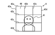
図2は、表示部に表示される風範囲指定画像を例示する図である。
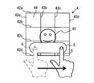
図3は、風範囲指定画像をドラッグ操作している状態を示す図である。
図4は、設定された風範囲に対応する風範囲図形が風範囲指定画像に重畳表示されている状態を示す図である。
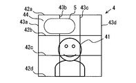
図5は、図4とは別の風範囲図形の表示例である。
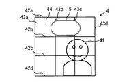
図6は、図4、5とは別の風範囲図形の表示例である。
図7は、乗員画像の位置が図6とは異なっている風範囲指定画像を示す図である。
図8は、タップ操作により設定された風範囲に対応する風範囲図形を例示する図である。
図9は、ミス操作の一例である斜め操作がされている状態を示す図である。
図10は、図9の斜め操作がされた後に設定される風範囲に対応して表示部に表示される風範囲図形を示す図である。
図11は、ミス操作の一例である顔始点操作がされている状態を示す図である。
図12は、図11の顔始点操作がされた後に設定される風範囲に対応して表示部に表示される風範囲図形5を示す図である。
図13は、ミス操作の一例である、はみ出し操作がされている状態を示す図である。
図14は、図13のはみ出し操作がされた後に設定される風範囲に対応して表示部に表示される風範囲図形を示す図である。
図15は、第2実施形態の表示例であり、マルチタッチによりドラッグ操作された場合の表示例である。
図16は、図15の操作が終わった後の表示例である。
図17は、第2実施形態の表示例であり、風範囲指定画像の中央部が強押し操作がされる直前の表示例である。
図18は、図17の人差し指の位置で強押し操作がされた後の表示例である。
図19は、第2実施形態の表示例であり、風範囲指定画像の左端部が強押し操作がされる直前の表示例である。
図20は、図19の人差し指の位置で強押し操作がされた後の表示例である。
<第1実施形態>
以下、実施形態を図面に基づいて説明する。
以下、実施形態を図面に基づいて説明する。
(車両用空調システム100の構成)
図1に示す車両用空調システム100は、車両に搭載される。この車両用空調システム100は、車両用空調装置(以下、空調装置)1、設定装置2、顔位置認識装置3を含んでいる。以降では、車両用空調システム100を搭載した車両を自車と呼ぶ。
図1に示す車両用空調システム100は、車両に搭載される。この車両用空調システム100は、車両用空調装置(以下、空調装置)1、設定装置2、顔位置認識装置3を含んでいる。以降では、車両用空調システム100を搭載した車両を自車と呼ぶ。
空調装置1は、自車の車室内を空調する装置である。空調装置1は、図1に示すように、エアコンECU11、横ルーバ12、横ルーバ用モータ13、縦ルーバ14、縦ルーバ用モータ15、温度調整部16、ブロア17を備えている。
横ルーバ12は、吹き出し口、あるいは、吹き出し口よりも風の流路の上流側に設けられており、横方向すなわち自車の車幅方向に延びるように形成されている複数の長板を備える。これら複数の長板は、その長板の長手方向に対して交差する方向に、互いに間隔をおいて配列されている。横ルーバ12の各長板は、その長板の長手方向に延びたシャフトを中心に回動可能に配置されている。
横ルーバ用モータ13は、横ルーバ12の各長板のシャフト駆動用のモータであって、各長板のシャフトを個別に駆動できるように例えば複数個のモータからなる。
縦ルーバ14は、吹き出し口、あるいは、吹き出し口よりも風の流路の上流側において、横ルーバ12の付近に設けられている。縦ルーバ14は、横ルーバ12の配列方向に延びるように形成されている複数の長板を備える。これら複数の長板は、横ルーバ12の長板の長手方向に互いに間隔をおいて配列されている。縦ルーバ14の各長板は、その長板の長手方向に延びたシャフトを中心に回動可能に配置されている。
縦ルーバ用モータ15は、縦ルーバ14の各長板のシャフト駆動用のモータであって、各長板のシャフトを個別に駆動できるように例えば複数個のモータからなる。
縦ルーバ14の向きが縦ルーバ用モータ15により制御されることで、その縦ルーバ14の下流にある吹き出し口から吹き出される風の左右方向の向き、および、風の集中拡散度合いが調整される。
具体的には、縦ルーバ14の隣接する長板同士の間隔が、吹き出し方向に向かうほど狭くなるようにすると、吹き出す風の左右方向の幅が狭くなる。反対に、縦ルーバ14の隣接する長板同士の間隔が、吹き出し方向に向かうほど広くなるようにすると、吹き出す風の左右方向の幅が広くなる。
また、縦ルーバ14の各長板間の吹き出し口側の間隔を維持したまま、縦ルーバ14の各長板を回動させると、風の集中拡散度合いが保持されたまま、風向きが自車の右方向や左方向に調整される。
横ルーバ12の向きが横ルーバ用モータ13により制御されることで、その横ルーバ12の下流にある吹き出し口から吹き出される風の上下方向の向きが調整される。なお、本実施形態では、吹き出し口から吹き出される風の上下方向の集中拡散度合いは調整しないとして説明する。ただし、吹き出し口から吹き出される風の上下方向の集中拡散度合いを調整するようにしてもよい。横ルーバ12の隣接する長板同士の間隔が、吹き出し方向に向かうほど狭くなるようにすれば、吹き出す風の上下方向の幅を狭くできる。反対に、横ルーバ12の隣接する長板同士の間隔が、吹き出し方向に向かうほど広くなるようにすれば、吹き出す風の上下方向の幅を広くできる。
温度調整部16は、熱交換器を備えており、吹き出し口から吹き出す風の温度を調整する。ブロア17は、吹き出し口から吹き出される風の風量を調整する。
エアコンECU11は、CPU、ROMやRAM等のメモリなどを備え、設定装置2から入力される信号をもとに、ROMに記憶された制御プログラムを実行することで、自車の空調に関する処理を実行する。なお、エアコンECU11が実行する機能の一部または全部を、一つあるいは複数のIC等によりハードウェア的に構成してもよい。
空調に関する処理としては、温度調整部16を用いた車室の温度制御、ブロア17を用いた風量の制御、横ルーバ12、横ルーバ用モータ13、縦ルーバ14、縦ルーバ用モータ15を用いた風の向きおよび風の集中拡散度合いの調整などがある。
車両用空調設定装置である設定装置2は、ディスプレイECU21、表示部22、タッチパネル23を備えている。表示部22は、カラー表示が可能なものであり、液晶ディスプレイ等を用いて構成することができる。この表示部22にタッチパネル23が重ねられている。タッチパネル23が重ねられている表示部22は、運転席に着座した運転者の手が届く位置に配置されている。
ディスプレイECU21は、CPU、ROMやRAM等のメモリなどを備え、CPUがRAMの一時記憶機能を利用しつつ、ROMに記憶された制御プログラムを実行することで、ディスプレイECU21は表示制御部211、空調設定部212として機能する。なお、本実施形態では、ディスプレイECU21が表示制御部211、空調設定部212として機能するが、別々のECUが、それぞれ表示制御部211、空調設定部212として機能してもよい。また、ディスプレイECU21が実行する機能の一部または全部を、一つあるいは複数のIC等によりハードウェア的に構成してもよい。
表示制御部211は、表示部22に、空調装置1に対する設定を行うための種々の設定画像を表示させる。この設定画像には、図2などに示す風範囲指定画像4が含まれる。また、空調装置1が行なっている空調の状態を示す画面も、表示部22に表示させる。
空調設定部212は、表示部22に、空調装置1に対する設定を行うための設定画面が表示されている状態で、タッチパネル23から入力される信号に基づいて、空調装置1に対する種々の設定を行う。
空調装置1に対する設定としては、温度設定、吹き出し口の選択、風量の設定などがある。また、運転席付近への風の向き、および、その風の集中拡散度合いの設定、助手席付近への風の向き、および、その風の集中拡散度合いの設定もある。したがって、空調設定部212は請求項の風範囲設定部に相当する。
運転席付近への風の向き、および、その風の集中拡散度合いの設定は、表示制御部211が表示部22に風範囲指定画像4を表示している状態で行う。また、助手席付近への風の向き、および、その風の集中拡散度合いの設定も、表示制御部211が表示部22に風範囲指定画像4を表示している状態で行う。
顔位置認識装置3は、前席乗員(すなわち運転者と助手席の乗員)の顔およびその付近を撮影するカメラと、そのカメラが撮影した画像を解析して、前席乗員の顔位置を決定する制御部とを備えた公知の構成である。顔位置認識装置3は、決定した前席乗員の顔位置を表す信号をディスプレイECU21の表示制御部211に逐次出力する。
(風範囲の設定)
次に、空調設定部212が行う運転席付近への風の向き、および、その風の集中拡散度合いの設定、助手席付近への風の向き、およびその風の集中拡散度合いの設定について説明する。
次に、空調設定部212が行う運転席付近への風の向き、および、その風の集中拡散度合いの設定、助手席付近への風の向き、およびその風の集中拡散度合いの設定について説明する。
風の向き、風の集中拡散度合いを設定するために、本実施形態では、風範囲を設定する。空調設定部212は、タッチパネル23に対して風範囲指定画像4を表示させる操作が行われた場合、表示制御部211に対して、図2に示す風範囲指定画像4を表示部22に表示させる指示を出力する。
風範囲指定画像4を表示させる操作は、運転席および助手席に対して、それぞれ行うことができる。運転席に対する風範囲指定画像4を用いて、運転席付近への風範囲が設定でき、助手席に対する風範囲指定画像4を用いて、助手席付近への風範囲が設定できる。風範囲指定画像4が表示された後の運転席付近への風範囲の設定方法と、助手席付近への風範囲の設定方法は同じである。
本実施形態の風範囲指定画像4は、正方形状であり、乗員画像41と、グリッド横線42と、グリッド縦線43とを含んでいる。乗員画像41は、前席に着座している乗員を表した画像である。本実施形態の乗員画像41は、前席乗員を実際に撮影した画像ではなく、予め用意された画像である。ただし、実際に運転者あるいは助手席乗員を撮影した画像を乗員画像41としてもよい。
表示制御部211には、前述したように、顔位置認識装置3が認識した前席乗員の顔位置を表す信号が入力される。表示制御部211は、この信号に基づいて、風範囲指定画像4内における乗員画像41の位置が、実際の前席乗員の位置に対応するように、乗員画像41の表示位置を更新する。
グリッド横線42は、風範囲指定画像4に複数表示されている。具体的には、図2には4本のグリッド横線42a、42b、42c、42dが表示されている。複数のグリッド横線42a、42b、42c、42dを区別しないときは単にグリッド横線42とする。4本のグリッド横線42は、いずれも車幅方向に延びており、互いに平行であり、かつ、等間隔に配置されている。グリッド横線42の間隔は、タッチパネル23を指先で触れたときのタッチパネル23に対する指先の上下方向の接触長さよりも長く、たとえば、その接触長さの2倍程度である。
グリッド縦線43も、風範囲指定画像4に複数、具体的には、4本のグリッド縦線43a、43b、43c、43dが表示されている。複数のグリッド縦線43a、43b、43c、43dを区別しないときは単にグリッド縦線43とする。これら4本のグリッド縦線43は上下方向に延びており、互いに平行であり、かつ、等間隔に配置されている。
さらに、本実施形態では、グリッド横線42の間隔と、グリッド縦線43の間隔は等しい。したがって、2本のグリッド横線42と、2本のグリッド縦線43とにより囲まれる矩形範囲44は正方形となる。図2に示す風範囲指定画像4は、各4本のグリッド横線42、グリッド縦線43により、3行、3列の矩形範囲44が形成されている。
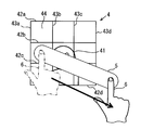
図3は、風範囲指定画像4上を、人差し指6によりドラッグ操作している状態を示している。広く知られているように、ドラッグ操作は、指などの操作体をタッチパネル23の表面に接触させたまま、その操作体をタッチパネル23の表面に沿って移動させる操作である。これに対してタップ操作は、操作体によりタッチパネル23に触れた後、その操作体をスライドさせないでタッチパネル23から離す。よって、ドラッグ操作は、タップ操作よりも、タッチパネル23の表面に沿った方向への操作距離が大きい操作であり、請求項の操作量大操作に相当する。
図3に示すドラッグ操作は、始点が左下の矩形範囲44であり、右下の矩形範囲44を終点として、始点から終点まで、グリッド横線42c、42dの間を、グリッド横線42c、42dを横切らないように人差し指6が移動する操作である。
このドラッグ操作が行われている過程では、図3に示すように、ドラッグ操作の始点から人差し指6の位置まで延びる風範囲図形5が、人差し指6の移動に伴い逐次更新されて、風範囲指定画像4に重畳して表示される。風範囲図形5も表示制御部211が表示部22に表示させる。
図3に示したドラッグ操作は、始点、終点の間をそのまま風範囲に設定できる正常操作である。ドラッグ操作が正常操作である場合には、ドラッグ操作が終了すると、すなわち、人差し指6が図3には図示しないタッチパネル23から離れると、図4に示すように、ドラッグ操作始点からドラッグ操作終点まで延びる風範囲図形5がそのまま表示される。
第1実施形態では、タッチパネル23から操作体が離れると、その時点で、風範囲図形5および風範囲が確定する。風範囲図形5が表示されている状態で新たに風範囲指定画像4上がタッチ操作されると、表示制御部211は、それまで表示されていた風範囲図形5を消去して、新たなタッチ操作に基づいて定まる風範囲図形5を表示する。空調設定部212は、新たに表示された風範囲図形5に対応した風範囲を設定する。
(正常操作の場合の風範囲)
空調設定部212は、ドラッグ操作が正常操作であれば、そのドラッグ操作の始点から終点までの範囲に基づいて風範囲を設定する。ドラッグ操作が正常操作ではない場合、ドラッグ操作された範囲をそのまま風範囲に設定できない。正常操作ではないドラッグ操作を、以下、ミス操作という。具体的なミス操作およびミス操作であった場合に設定する風範囲は後述する。まず、正常操作である場合に設定する風範囲について説明する。
空調設定部212は、ドラッグ操作が正常操作であれば、そのドラッグ操作の始点から終点までの範囲に基づいて風範囲を設定する。ドラッグ操作が正常操作ではない場合、ドラッグ操作された範囲をそのまま風範囲に設定できない。正常操作ではないドラッグ操作を、以下、ミス操作という。具体的なミス操作およびミス操作であった場合に設定する風範囲は後述する。まず、正常操作である場合に設定する風範囲について説明する。
風範囲指定画像4は、前席乗員が通常位置している範囲と対応付けられている。具体的には、運転席が指定された場合の風範囲指定画像4は、運転席に着座した運転者が通常乗員画像41の位置となる範囲と対応している。助手席が指定された場合の風範囲指定画像4は、助手席に着座した乗員が通常乗員画像41の位置となる範囲と対応している。
したがって、風範囲指定画像4に重畳表示される風範囲図形5は、運転者あるいは助手席乗員の付近に吹き出される風の範囲を表している。本実施形態では、上下方向における風の範囲は、2本のグリッド横線42により挟まれる範囲を単位とする。一方、左右方向における風の範囲は、グリッド縦線43とは関係なく、風範囲指定画像4上のドラッグ操作の始点から終点までを範囲とする。
図3に示したドラッグ操作がされて風範囲が設定された場合には、前席乗員に向けて吹き出し口から吹き出される風は、上下方向の向きが、図3、図4に示す2本のグリッド横線42c、42dの間に対応する向きとなる。また、左右方向の向きおよび集中拡散度合いは、風範囲指定画像4の左右方向のほぼ全体に対応する向きおよび拡散度合いとなる。なお、前席乗員に風を吹き出す吹き出し口は、1つでも複数でもよい。
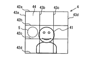
図5、図6も、ドラッグ操作が正常操作であった場合におけるドラッグ操作終了後の風範囲図形5の表示例である。図5の位置に風範囲図形5が表示されている場合、前席乗員に向けて吹き出し口から吹き出される風は、上下方向の向きが、2本のグリッド横線42a、42bの間に対応する向きとなる。左右方向の向きおよび集中拡散度合いは、グリッド縦線43a、43bの間から、グリッド縦線43b、43cの間までの向きおよび集中拡散度合いとなる。
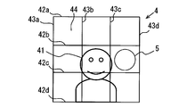
図6の位置に風範囲図形5が表示されている場合、前席乗員に向けて吹き出し口から吹き出される風は、上下方向の向きは図5と同じである。左右方向の向きおよび集中拡散度合いは、グリッド縦線43a、43bの間から、グリッド縦線43c、43dの間までの向きおよび集中拡散度合いとなる。なお、左右方向の風の向きは図5と異なるが、集中拡散度合いは図5と同じである。
図7の表示例は、風範囲図形5の表示位置および大きさは図6と同じであるが、乗員画像41の位置が、図6と異なる。図7における乗員画像41の位置が図6と異なる理由は、表示制御部211は、顔位置認識装置3から入力された信号に基づいて、風範囲指定画像4内における乗員画像41を、実際の前席乗員の位置に対応する位置に表示するからである。
図8の表示例は、ドラッグ操作ではなく、タップ操作が行われた場合におけるタップ操作終了後の風範囲図形5の表示例である。タップ操作が行われた場合には、空調設定部212は、タップ操作に基づいて定まる最小範囲を風範囲に設定する。
前述したように、本実施形態では、風範囲の左右方向の範囲はグリッド縦線43とは関係なく設定する。したがって、タップ操作された場合には、タップ操作により定まる位置を含み、左右方向の最小長さの範囲を、風範囲の左右方向の範囲とする。左右方向の最小長さは、空調装置1が最も集中した風を吹き出したときの、その風の左右方向の長さに基づいて定める。上下方向における風の範囲は、2本のグリッド横線42により挟まれる範囲を単位としているので、タップ操作された場合における風範囲の上下方向の範囲は、タップ操作された位置を挟んでいる2本のグリッド横線42の間とする。
(ミス操作の場合の風範囲)
次に、ドラッグ操作がミス操作であった場合に設定する風範囲について説明する。ミス操作は、空調装置1が設定できない風の範囲を指定するドラッグ操作である。本実施形態におけるミス操作は、具体的には、下記(1)~(3)である。(1)ドラッグ操作がグリッド横線42を横切る操作。以下、この操作を斜め操作という。(2)ドラッグ操作の始点が乗員画像41の顔の位置である操作。以下、この操作を顔始点操作という。(3)ドラッグ操作の始点および終点の少なくとも一方が風範囲指定画像4の外に位置している操作。以下、この操作をはみ出し操作という。
次に、ドラッグ操作がミス操作であった場合に設定する風範囲について説明する。ミス操作は、空調装置1が設定できない風の範囲を指定するドラッグ操作である。本実施形態におけるミス操作は、具体的には、下記(1)~(3)である。(1)ドラッグ操作がグリッド横線42を横切る操作。以下、この操作を斜め操作という。(2)ドラッグ操作の始点が乗員画像41の顔の位置である操作。以下、この操作を顔始点操作という。(3)ドラッグ操作の始点および終点の少なくとも一方が風範囲指定画像4の外に位置している操作。以下、この操作をはみ出し操作という。
ドラッグ操作がミス操作である場合には、ドラッグ操作範囲の一部に基づいて風範囲を設定する。たとえば、斜め操作であって、かつ、顔始点操作でない場合には、ドラッグ操作範囲の一部として、風範囲指定画像4上のドラッグ操作始点を用い、このドラッグ操作始点に基づいて定まる範囲を風範囲とする。
図9は、ドラッグ操作の方向が右斜め下に向かう方向であるため、ドラッグ操作がグリッド横線42cを横切っている例である。この図9に示すように、ドラッグ操作がミス操作であっても、ドラッグ操作が行われている間は、風範囲図形5は、人差し指6の移動に伴い逐次更新されて表示される。
図10は、図9の状態からドラッグ操作が終了した後に表示される風範囲図形5が重畳表示された風範囲指定画像4を示している。図10に示す風範囲図形5は、ドラッグ操作の始点が含まれている矩形範囲44内に表示されている。この風範囲図形5の上下方向の長さは、正常時の風範囲図形5と同じであり、左右方向の長さは、ミス操作時に設定する予め設定された左右方向長さになっている。
この図10に示す風範囲図形5が表示部22に表示されている場合の風範囲は、上下方向の風の向きが、グリッド横線42b、42cの間であり、左右方向の風の向きは、ドラッグ操作の始点が含まれている矩形範囲44内である。また、集中拡散度合いは、最も集中した状態である。
なお、図9は、ドラッグ操作の終点が風範囲指定画像4の外に位置していることから、はみ出し操作でもある。しかし、本実施形態では、斜め操作に対する処置を、はみ出し操作に対する処置よりも優先させる。
ミス操作が顔始点操作である場合、ドラッグ操作範囲のうち、風範囲指定画像4上において乗員画像41よりも右側部分の一部または全部を風範囲に設定する。そして、この風範囲に対応する風範囲図形5を風範囲指定画像4に重畳表示する。ドラッグ操作範囲のうち、乗員画像41よりも右側部分の一部は、たとえば、乗員画像41よりも右側にある矩形範囲44である。
なお、乗員位置によっては、乗員画像41が風範囲指定画像4の中心から移動しており、ドラッグ操作範囲のうち、乗員画像41よりも右側部分がない場合もある。その場合には、風範囲は設定しない。
図11は、顔位置始点操作が行われている途中の表示例である。図12は、図11の状態からドラッグ操作が終了した後に表示される、風範囲図形5が重畳表示された風範囲指定画像4を示している。
ドラッグ操作の始点が乗員画像41の顔位置であれば、図12に示すように、乗員画像41の顔位置よりもドラッグ操作範囲の終点に近い矩形範囲44である、右端列の中段の矩形範囲44内に風範囲図形5が表示される。そして、この風範囲図形5に対応する範囲が風範囲に設定される。
なお、図11は、ドラッグ操作がグリッド横線42bを横切っていることから、斜め操作でもある。しかし、本実施形態では、顔位置始点操作に対する処置を、斜め操作に対する処置よりも優先させる。したがって、図11のドラッグ操作が行われた場合、図12に示す位置に風範囲図形5を表示し、図12に表示した風範囲図形5対応する範囲を風範囲に設定する。
はみ出し操作の場合には、空調設定部212は、ドラッグ操作範囲のうち、風範囲指定画像4上の範囲を風範囲に設定し、表示制御部211に、その風範囲に対応する風範囲図形5を風範囲指定画像4に重畳表示させる。
図13は、ドラッグ操作範囲の始点および終点ともに風範囲指定画像4の外に位置している場合におけるドラッグ操作中の表示例である。図14は、図13の状態からドラッグ操作が終了した後に表示される、風範囲図形5が重畳表示された風範囲指定画像4を示している。
図13に示すように、ドラッグ操作範囲が、グリッド横線42は横切っていないが、その始点および終点が風範囲指定画像4の外に位置している場合、図14に示すように、ドラッグ操作範囲のうち、風範囲指定画像4上の始点から終点までの範囲が風範囲に設定され、その風範囲に対応する風範囲図形5が、風範囲指定画像4に重畳表示される。
(第1実施形態まとめ)
以上、説明した本実施形態では、前席乗員に対して吹き出し口から吹き出される風の向きおよび風の集中拡散度合いを調整する場合には、表示制御部211は、タッチパネル23が重畳された表示部22に、風範囲指定画像4を表示する。
以上、説明した本実施形態では、前席乗員に対して吹き出し口から吹き出される風の向きおよび風の集中拡散度合いを調整する場合には、表示制御部211は、タッチパネル23が重畳された表示部22に、風範囲指定画像4を表示する。
空調設定部212は、表示部22に風範囲指定画像4が表示された状態で、タッチパネル23がドラッグ操作された場合には、ドラッグ操作された範囲に基づいて、風の向きおよび風の集中拡散度合いを表す風範囲を設定する。よって、ドラッグ操作という1つの操作により、風の向きおよび風の集中拡散度合いが設定できるので、簡単な操作で、吹き出し口から吹き出される風の向きと集中拡散度合いとを設定できる。
また、本実施形態では、空調設定部212は、表示部22に風範囲指定画像4が表示された状態で、タッチパネル23がタップ操作された場合には、タップ操作に基づいて定まる最小範囲を風範囲に設定する。したがって、吹き出し口から吹き出される風を最も集中した状態に設定し、かつ、その最も集中した状態の風の向きを設定する操作も簡単に行える。
また、乗車中に、人が、正確に横方向に一直線にドラッグ操作をすることは困難であり、一直線にドラッグ操作をしようとしても、ドラッグ操作の範囲は、少し湾曲した形状となる。一方、意図的に、少し湾曲した形状でドラッグ操作をすることはほとんどないと考えられる。そこで、本実施形態では、空調設定部212は、風範囲指定画像4上がドラッグ操作され、そのドラッグ操作がグリッド横線42を横切らない場合、横方向に一直線にドラッグ操作がされたとして風範囲を設定する。これにより、乗員は、横方向に一直線に風範囲を指定する意図があったにも関わらず、ドラッグ操作が少し湾曲してしまったとしても、乗員の意図通りに一直線に風範囲が設定される。
また、本実施形態では、ドラッグ操作が、空調装置1が設定できない風の範囲を指定するミス操作である場合、空調設定部212は、ドラッグ操作の範囲のうち、風範囲指定画像4上の一部分であって、風範囲指定画像4上の始点および終点のいずれか一方を含む範囲に基づいて、風範囲を設定する。したがって、ミス操作であっても、風範囲を設定することができる。
ミス操作のうち、斜め操作であって、顔位置始点操作でない場合、空調設定部212は、ドラッグ操作範囲のうち、風範囲指定画像4上の始点に基づいて風範囲を設定する。斜め操作になってしまった場合、ドラッグ操作の開始側よりも、ドラッグ操作の終了側が意図した位置からずれている場合が多い。したがって、斜め操作である場合に、ドラッグ操作範囲のうち、風範囲指定画像4上の始点に基づいて風範囲を設定すれば、ドラッグ操作者の意図を比較的反映した風範囲となる可能性が高くなる。
また、意図せずに、前席乗員の顔に風が当たってしまうと、前方の視認性が低下してしまう恐れがある。そこで、本実施形態では、顔始点操作である場合、乗員画像41の部分は風範囲に設定しない。これにより、ドラッグ操作が顔始点操作になってしまったとしても、前席乗員の顔に風が当たってしまうことを防止できる。
ここで、顔始点操作となってしまったドラッグ操作をした乗員は、実際には、乗員画像41の左側を始点としようとした可能性もあり、また、乗員画像41の右側を始点としようとした可能性もある。したがって、顔始点操作がされた場合に設定する風範囲を、乗員画像41の右側としても、また、左側としても、乗員の意図に反する可能性がある。そのため、顔始点操作がされた場合には、乗員は再度、ドラッグ操作をやり直す可能性も高い。
ドラッグ操作は、右利きでも、また、左利きでも、文字を書く場合と同じく、左から右へ指を移動させる方が、右から左へ指を移動させるよりも、行いやすい。したがって、再度、ドラッグ操作をする場合には、左から右へドラッグ操作をすることになる。その再度のドラッグ操作の際に、ドラッグ操作の始点となる乗員画像41の左側に、風範囲図形5が表示されていると、心理的に、再度のドラッグ操作を行いにくくなる。
しかし、本実施形態では、顔始点操作である場合、ドラッグ操作範囲のうち、風範囲指定画像4上において乗員画像41よりも右側部分の一部または全部を風範囲に設定する。したがって、再度のドラッグ操作が行いやすくなる。
<第2実施形態>
次に、第2実施形態を説明する。この第2実施形態以下の説明において、それまでに使用した符号と同一番号の符号を有する要素は、特に言及する場合を除き、それ以前の実施形態における同一符号の要素と同一である。また、構成の一部のみを説明している場合、構成の他の部分については先に説明した実施形態を適用できる。
次に、第2実施形態を説明する。この第2実施形態以下の説明において、それまでに使用した符号と同一番号の符号を有する要素は、特に言及する場合を除き、それ以前の実施形態における同一符号の要素と同一である。また、構成の一部のみを説明している場合、構成の他の部分については先に説明した実施形態を適用できる。
第2実施形態では、タッチパネル23は、マルチタッチを検出することができ、かつ、タッチパネル23への押圧力を複数レベルに区分して検出できる構成である。レベル数は、本実施形態では、風範囲指定画像4において左右方向の矩形範囲44の数に対応して3である。第2実施形態のタッチパネル23には公知の種々の構成のものを用いることができる。たとえば、静電容量式のセンサと圧力センサを積層したタッチパネルを用いればよい。
なお、第1実施形態のタッチパネル23は、マルチタッチを検出できる必要はなく、また、タッチパネル23にタッチされたことを検出できればよいので、押圧力は検出しない静電容量式を用いることができる。ただし、第1実施形態にも、第2実施形態で用いるものと同じタッチパネル23を用いてもよい。
第2実施形態において、空調設定部212は、第1実施形態と同じ機能を備える。第1実施形態と同様にして風範囲が設定されるのは、タッチパネル23がシングルタッチされ、かつ、押圧力が最も低い押圧力レベルである場合である。
タッチパネル23がマルチタッチされた場合、および、タッチパネル23への押圧力が2番目以上の押圧力レベルである場合には、空調設定部212は、第1実施形態と異なる風範囲を設定する。なお、マルチタッチは、タッチパネル23上の複数の位置が同時にタッチされる状態である。
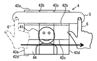
タッチパネル23がマルチタッチされた場合には、複数のタッチ位置のそれぞれに基づいて第1実施形態と同じ風範囲を設定する。したがって、マルチタッチによりドラッグ操作された場合には、それぞれのドラッグ操作に対して第1実施形態と同じ処理を行って風範囲を設定する。図15は、人差し指6と中指7が、風範囲指定画像4上をドラッグ操作している状態を示している。人差し指6によるドラッグ操作は、始点が左下の矩形範囲44内であり、終点は右下の矩形範囲44内である。中指7によるドラッグ操作は、始点が左列の上下中央の矩形範囲44内であり、終点が右列の上下中央の矩形範囲44内である。
人差し指6と中指7によりそれぞれドラッグ操作が行われている過程でも、ドラッグ操作の始点から人差し指6と中指7まで延びる風範囲図形5a、5bが、人差し指6と中指7移動に伴い逐次更新されて、風範囲指定画像4に重畳して表示される。
人差し指6と中指7によるドラッグ操作は、それぞれ、第1実施形態と同様に、正常操作かミス操作かが判断され、正常操作、ミス操作に応じた範囲に風範囲が設定される。図16は、人差し指6によるドラッグ操作、および、中指7によるドラッグ操作がともに正常操作であった場合に表示される風範囲図形5a、5bである。ドラッグ操作が正常操作であるので、図16に示す風範囲図形5a、5bは、ドラッグ操作始点からドラッグ操作終点まで延びている。空調設定部212は、この図16に示す風範囲図形5a、5bに対応する風範囲を設定する。
次に、タッチパネル23への押圧力が2番目以上の押圧力レベルである場合に、空調設定部212が設定する風範囲を説明する。2番目以上の押圧力レベルであるタッチパネル23への操作を、以下、強押し操作という。なお、押圧力が最も低い押圧力レベルであり、ドラッグ操作されることなく、タッチパネル23への操作が終了した場合はタップ操作と判断する。よって、強押し操作は、タップ操作よりも押圧力が大きい操作であり、請求項の操作量大操作に相当する。
タッチパネル23に対して強押し操作がされた場合には、強押し操作の操作位置が風範囲指定画像4内であれば、強押し操作がされた位置に基づいて定まる基準範囲に加えて、基準範囲の左右いずれか一方に延びた範囲を風範囲に設定する。
本実施形態における基準範囲は、タップ操作時に設定される最小範囲と同じである。この基準範囲に対して左右いずれの方向に風範囲を延ばすかは、強押し操作が行われた位置により異なる。
強押し操作が行われた位置が風範囲指定画像4の右端部であれば、風範囲を基準範囲から左方向に延ばす。反対に、強押し操作が行われた位置が風範囲指定画像4の左端部であれば、風範囲を基準範囲から右方向に延ばす。なお、本実施形態における端部は矩形範囲44の1つ分とする。ただし、本実施形態とは異なり、端部を矩形範囲44よりも小さくしたり、矩形範囲44よりも大きくしたりしてもよい。
基準範囲に対して延ばす部分の風範囲の左右方向の長さは、押圧力のレベルに応じて定まる。具体的には、押圧力レベルが2番目に低い押圧力レベル、換言すれば、強押し操作としては最も低い押圧力レベルであれば、一つ分の矩形範囲44に相当する長さを、基準範囲から延ばす。
押圧力レベルが3番目に低い押圧力レベル、換言すれば、強押し操作としては2番目に低い押圧力レベルであれば、2つ分の矩形範囲44に相当する長さだけ、基準範囲に対して延ばした範囲を風範囲とする。なお、上下方向の長さは、基準範囲から変更しない。
強押し操作が行われた位置が風範囲指定画像4の中央部であれば、風範囲を左右方向両側に延ばす。ただし、本実施形態では、風範囲を左右同時に延ばすのではなく、タッチパネル23に対する押圧力が2番目の押圧力レベルであれば右側に風範囲を延ばす。風範囲指定画像4の中央部は、本実施形態では、風範囲指定画像4に含まれる3列の矩形範囲44のうち中央の列である。ただし、中央部を、中央の列の矩形範囲44よりも広くしても良いし、反対に、中央の列の矩形範囲よりも狭くしてもよい。
タッチパネル23に対する押圧力がさらに強くなり、3番目に低い押圧力レベルであれば、右側に加えて左側にも風範囲を延ばす。風範囲を延ばす長さは、1つ分の矩形範囲44に相当する長さである。
強押し操作が行われたときも、その操作中に、風範囲に対応する風範囲図形5が風範囲指定画像4の上に重畳表示される。図17は、風範囲指定画像4内の乗員画像41の顔が表示されている部分に人差し指6が触った状態を示している。操作当初は、押圧力が最も低い押圧力レベルであるので、タップ操作された場合と同じ範囲の風範囲図形5が表示される。
その後、押圧力が2番目に低い押圧力レベルになったことが検出されると、風範囲図形5は図17の範囲から右側に延びる。さらに、押圧力が3番目に低い押圧力レベルになったことが検出されると、風範囲図形5は、図18に示すように、図17に示した風範囲図形5に対して左右に延びた形状となる。
図19は、風範囲指定画像4内の左端列の上下中央の矩形範囲44内に、人差し指6が触った状態を示している。この状態では表示される風範囲図形5は、人差し指6が触れている位置がタップ操作された場合と同じである。その後、押圧力が2番目に低い押圧力レベルになったことが検出されると、風範囲図形5は、図20に示すように、図19に示した風範囲図形に対して、右側に、矩形範囲44、1つ分延びた形状となる。
この第2実施形態では、タッチパネル23の風範囲指定画像4上の位置が、マルチタッチによりドラッグ操作された場合、それぞれのドラッグ操作に基づいて風範囲を設定する。よって、シングルタッチによるドラッグ操作で指定する風範囲よりも広い風範囲を、簡単な操作で設定できる。
また、第2実施形態では、強押し操作によっても風範囲を設定できる。よって、吹き出し口から吹き出される風の向きと風の集中拡散度合いを、強押し操作という一つの操作で簡単に設定できる。
以上、実施形態を例示したが、実施形態は上述の実施形態に限定されるものではなく、次の変形例を含む種々な態様に変更できる。
<変形例1>
たとえば、前述の実施形態では、グリッド横線42、グリッド縦線43の数は、それぞれ4本ずつであったが、グリッド横線42、グリッド縦線43の数は5本以上であってもよい。また、グリッド横線42の数とグリッド縦線43の数が同じでなくてもよい。
たとえば、前述の実施形態では、グリッド横線42、グリッド縦線43の数は、それぞれ4本ずつであったが、グリッド横線42、グリッド縦線43の数は5本以上であってもよい。また、グリッド横線42の数とグリッド縦線43の数が同じでなくてもよい。
<変形例2>
また、前述の実施形態では、左右方向における風の範囲は、グリッド縦線43とは関係なく設定されていたが、2本のグリッド縦線43で挟まれる範囲を単位として、左右方向における風の範囲を設定してもよい。
また、前述の実施形態では、左右方向における風の範囲は、グリッド縦線43とは関係なく設定されていたが、2本のグリッド縦線43で挟まれる範囲を単位として、左右方向における風の範囲を設定してもよい。
<変形例3>
前述の実施形態では、斜め操作をミス操作としていたが、斜め操作をミス操作とせずに、斜めに風範囲を設定してもよい。
前述の実施形態では、斜め操作をミス操作としていたが、斜め操作をミス操作とせずに、斜めに風範囲を設定してもよい。
<変形例4>
前述の実施形態では、横ルーバ12の各長板、縦ルーバ14の各長板の角度を調整することにより風範囲を調整していたが、ルーバに代えて、あるいは、ルーバに加えて、コアンダ効果を利用して、風範囲を調整してもよい。
前述の実施形態では、横ルーバ12の各長板、縦ルーバ14の各長板の角度を調整することにより風範囲を調整していたが、ルーバに代えて、あるいは、ルーバに加えて、コアンダ効果を利用して、風範囲を調整してもよい。
<変形例5>
第2実施形態では、風範囲を延ばす段階を押圧力レベルに応じて決定しており、それに伴い、タッチパネル23に加えられる押圧力を3つのレベルに区分して検出できるようにしていた。しかし、タッチパネル23に加えられる押圧力の検出区分は2段階でもよいし、4段階以上とし、これらの段階数に応じて、風範囲を延ばす段階数を設定してもよい。
第2実施形態では、風範囲を延ばす段階を押圧力レベルに応じて決定しており、それに伴い、タッチパネル23に加えられる押圧力を3つのレベルに区分して検出できるようにしていた。しかし、タッチパネル23に加えられる押圧力の検出区分は2段階でもよいし、4段階以上とし、これらの段階数に応じて、風範囲を延ばす段階数を設定してもよい。
<変形例6>
前述の実施形態では、タッチパネル23から操作体が離れると、その時点で、風範囲図形5および風範囲を確定させていた。そして、風範囲図形5が表示されている状態で、新たに風範囲指定画像4上がタッチ操作されると、それまで表示されていた風範囲図形5を消去して、新たなタッチ操作に基づいて定まる風範囲図形5を表示していた。
前述の実施形態では、タッチパネル23から操作体が離れると、その時点で、風範囲図形5および風範囲を確定させていた。そして、風範囲図形5が表示されている状態で、新たに風範囲指定画像4上がタッチ操作されると、それまで表示されていた風範囲図形5を消去して、新たなタッチ操作に基づいて定まる風範囲図形5を表示していた。
しかし、タッチパネル23から操作体が離れた後、予め設定した一定時間内であれば、風範囲図形5を追加できるようにしてもよい。このようにすれば、1本の指でドラッグ操作を行って、図15に示す風範囲図形5aを表示させた後、続いてドラッグ操作を行って風範囲図形5bを表示させて、これら2つの風範囲図形5a、5bに対応した風範囲を設定することができる。
<変形例7>
第2実施形態では、強押し操作が行われた位置が風範囲指定画像4の中央部である場合に、右側、左側の順に風範囲を延ばしていた。しかし、右側と左側を同時に延ばしてもよい。この場合、1段目に風範囲を延ばす長さは、たとえば、右側、左側を合計して第2実施形態において右側に風範囲を延ばす長さと同じになるようにする。また、右側、左側に延ばす長さを合計すると、第2実施形態において右側に延ばす長さよりも長くなるようにしてもよい。また、左側、右側の順に風範囲を延ばしてもよい。
第2実施形態では、強押し操作が行われた位置が風範囲指定画像4の中央部である場合に、右側、左側の順に風範囲を延ばしていた。しかし、右側と左側を同時に延ばしてもよい。この場合、1段目に風範囲を延ばす長さは、たとえば、右側、左側を合計して第2実施形態において右側に風範囲を延ばす長さと同じになるようにする。また、右側、左側に延ばす長さを合計すると、第2実施形態において右側に延ばす長さよりも長くなるようにしてもよい。また、左側、右側の順に風範囲を延ばしてもよい。
Claims (12)
- 車両に搭載され、吹き出し口から吹き出される風の向き、および、前記風の集中拡散度合いを設定できる車両用空調装置(1)とともに用いられ、
前記車両の座席に着座している乗員を表した乗員画像(41)を含む風範囲指定画像(4)を表示する表示部(22)と、
前記表示部に重畳されたタッチパネル(23)と、
前記風範囲指定画像上の前記タッチパネルの操作範囲に基づいて、前記風の向きおよび前記風の集中拡散度合いを表す風範囲を設定する風範囲設定部(212)とを備え、
前記風範囲設定部は、前記タッチパネルに対する、前記タッチパネルの表面に沿った方向への操作距離、および前記タッチパネルへの押圧力のいずれか一方である操作量が、タップ操作に比べて大きい操作量大操作がされた場合に、前記操作量大操作の操作量に基づいて、前記風範囲を設定する、
車両用空調設定装置。 - 請求項1において、
前記操作量大操作として、前記タッチパネルの表面に沿った方向への操作量が前記タップ操作に比べて大きい操作であるドラッグ操作を含み、
前記風範囲設定部は、前記タッチパネルが前記ドラッグ操作された場合、前記ドラッグ操作の範囲に基づいて、前記風範囲を設定する、
車両用空調設定装置。 - 請求項2において、
前記風範囲設定部は、前記タッチパネルが前記タップ操作された場合、前記タップ操作がされた位置に基づいて定まる最小範囲を前記風範囲に設定する、
車両用空調設定装置。 - 請求項2または3において、
前記タッチパネルが、マルチタッチにより前記ドラッグ操作された場合、複数の前記ドラッグ操作の範囲のそれぞれに基づいて、前記風範囲を設定する、
車両用空調設定装置。 - 請求項2~4のいずれか1項において、
前記風範囲指定画像は、複数の互いに平行な横線(42)を含んでおり、
前記風範囲設定部は、前記風範囲指定画像上の前記タッチパネルが前記ドラッグ操作された場合であって、前記ドラッグ操作が前記横線を横切らない場合、横方向に一直線に前記ドラッグ操作がされたとして、前記風範囲を設定する、
車両用空調設定装置。 - 請求項2~5のいずれか1項において、
前記風範囲設定部は、前記ドラッグ操作が、前記車両用空調装置が設定できない風の範囲を指定するミス操作である場合、前記ドラッグ操作の範囲のうち、前記風範囲指定画像上の一部分であって、前記風範囲指定画像上の始点および終点のいずれか一方を含む範囲に基づいて、前記風範囲を設定する、
車両用空調設定装置。 - 請求項6において、
前記風範囲設定部は、前記ドラッグ操作が前記ミス操作であり、かつ、前記乗員画像が前記ドラッグ操作の始点でない場合、前記ドラッグ操作の範囲のうち、前記風範囲指定画像上の一部分であって、前記風範囲指定画像上の始点を含む範囲に基づいて、前記風範囲を設定する、
車両用空調設定装置。 - 請求項6または7において、
前記風範囲設定部は、前記ドラッグ操作が前記ミス操作であり、かつ、前記乗員画像が前記ドラッグ操作の始点である場合、前記ドラッグ操作の範囲のうち、前記風範囲指定画像上において前記乗員画像よりも右側部分に基づいて、前記風範囲を設定する、
車両用空調設定装置。 - 請求項1~8のいずれか1項において、
前記操作量大操作として、前記タッチパネルへの押圧力が前記タップ操作に比べて大きい操作である強押し操作を含み、
前記タッチパネルは前記タップ操作と前記強押し操作とを区別可能に構成され、
前記風範囲設定部は、前記タッチパネルに対して前記強押し操作が行われた場合であって、前記強押し操作の操作位置が前記風範囲指定画像内であれば、前記強押し操作がされた位置に基づいて定まる基準範囲に加えて、前記基準範囲の左右いずれか少なくとも一方に延びた範囲を前記風範囲に設定する、
車両用空調設定装置。 - 請求項9において、
前記風範囲設定部は、前記タッチパネルに対して前記強押し操作が行われた場合であって、前記強押し操作の操作位置が前記風範囲指定画像内の左右方向端部であれば、前記基準範囲、および、前記基準範囲から前記風範囲指定画像の左右方向中央側に延びる範囲を前記風範囲に設定する、
車両用空調設定装置。 - 請求項9または10において、
前記風範囲設定部は、前記タッチパネルに対して前記強押し操作が行われた場合であって、前記強押し操作の操作位置が前記風範囲指定画像内の中央部であれば、前記基準範囲に加えて、前記基準範囲から前記風範囲指定画像の左右方向両側に延びる範囲を前記風範囲に設定可能である、
車両用空調設定装置。 - 請求項9~11のいずれか1項において、
前記タッチパネルは、前記強押し操作として複数段階の押圧力を検出可能であり、
前記風範囲設定部は、前記風範囲の左右方向の長さを、前記強押し操作の押圧力の大きさに応じて決定する、
車両用空調設定装置。
Priority Applications (1)
| Application Number | Priority Date | Filing Date | Title |
|---|---|---|---|
| US15/562,176 US10576807B2 (en) | 2015-04-02 | 2016-03-17 | Vehicle air conditioning setting device |
Applications Claiming Priority (4)
| Application Number | Priority Date | Filing Date | Title |
|---|---|---|---|
| JP2015-076214 | 2015-04-02 | ||
| JP2015076214 | 2015-04-02 | ||
| JP2016029763A JP6418176B2 (ja) | 2015-04-02 | 2016-02-19 | 車両用空調設定装置 |
| JP2016-029763 | 2016-02-19 |
Publications (1)
| Publication Number | Publication Date |
|---|---|
| WO2016157789A1 true WO2016157789A1 (ja) | 2016-10-06 |
Family
ID=57004220
Family Applications (1)
| Application Number | Title | Priority Date | Filing Date |
|---|---|---|---|
| PCT/JP2016/001531 Ceased WO2016157789A1 (ja) | 2015-04-02 | 2016-03-17 | 車両用空調設定装置 |
Country Status (1)
| Country | Link |
|---|---|
| WO (1) | WO2016157789A1 (ja) |
Cited By (2)
| Publication number | Priority date | Publication date | Assignee | Title |
|---|---|---|---|---|
| CN107477771A (zh) * | 2017-07-20 | 2017-12-15 | 广东美的制冷设备有限公司 | 导风板的控制方法、空调器以及控制装置和存储介质 |
| WO2022168579A1 (ja) * | 2021-02-05 | 2022-08-11 | 株式会社デンソー | 車両用制御装置及び車両用制御方法 |
Citations (6)
| Publication number | Priority date | Publication date | Assignee | Title |
|---|---|---|---|---|
| JP3952852B2 (ja) * | 2002-05-24 | 2007-08-01 | 日産自動車株式会社 | 空調システム |
| JP2008265675A (ja) * | 2007-04-24 | 2008-11-06 | Toyota Motor Corp | 車両用空調装置 |
| JP2010055598A (ja) * | 2008-07-31 | 2010-03-11 | Sony Corp | 情報処理装置および方法、並びにプログラム |
| JP2012118825A (ja) * | 2010-12-01 | 2012-06-21 | Fujitsu Ten Ltd | 表示装置 |
| JP2013076493A (ja) * | 2011-09-30 | 2013-04-25 | Hitachi Appliances Inc | 空調制御端末および空調制御の設定操作方法 |
| JP2015032276A (ja) * | 2013-08-06 | 2015-02-16 | 株式会社アスコ | 指示入力装置、指示入力検出方法、プログラムおよび記録媒体 |
-
2016
- 2016-03-17 WO PCT/JP2016/001531 patent/WO2016157789A1/ja not_active Ceased
Patent Citations (6)
| Publication number | Priority date | Publication date | Assignee | Title |
|---|---|---|---|---|
| JP3952852B2 (ja) * | 2002-05-24 | 2007-08-01 | 日産自動車株式会社 | 空調システム |
| JP2008265675A (ja) * | 2007-04-24 | 2008-11-06 | Toyota Motor Corp | 車両用空調装置 |
| JP2010055598A (ja) * | 2008-07-31 | 2010-03-11 | Sony Corp | 情報処理装置および方法、並びにプログラム |
| JP2012118825A (ja) * | 2010-12-01 | 2012-06-21 | Fujitsu Ten Ltd | 表示装置 |
| JP2013076493A (ja) * | 2011-09-30 | 2013-04-25 | Hitachi Appliances Inc | 空調制御端末および空調制御の設定操作方法 |
| JP2015032276A (ja) * | 2013-08-06 | 2015-02-16 | 株式会社アスコ | 指示入力装置、指示入力検出方法、プログラムおよび記録媒体 |
Cited By (5)
| Publication number | Priority date | Publication date | Assignee | Title |
|---|---|---|---|---|
| CN107477771A (zh) * | 2017-07-20 | 2017-12-15 | 广东美的制冷设备有限公司 | 导风板的控制方法、空调器以及控制装置和存储介质 |
| CN107477771B (zh) * | 2017-07-20 | 2020-04-21 | 广东美的制冷设备有限公司 | 导风板的控制方法、空调器以及控制装置和存储介质 |
| WO2022168579A1 (ja) * | 2021-02-05 | 2022-08-11 | 株式会社デンソー | 車両用制御装置及び車両用制御方法 |
| JP2022120636A (ja) * | 2021-02-05 | 2022-08-18 | 株式会社デンソー | 車両用制御装置及び車両用制御方法 |
| JP7491232B2 (ja) | 2021-02-05 | 2024-05-28 | 株式会社デンソー | 車両用制御装置及び車両用制御方法 |
Similar Documents
| Publication | Publication Date | Title |
|---|---|---|
| JP6418176B2 (ja) | 車両用空調設定装置 | |
| US9304676B2 (en) | Multi-use segments of touch screen control | |
| JPWO2022254665A5 (ja) | ||
| EP4350494A1 (en) | Equipment control device, equipment control method, and program | |
| US12508904B2 (en) | Display control apparatus and display control method | |
| US20100327070A1 (en) | Touch sensitive interface for heating or air conditioning a vehicle, and method for adjusting same | |
| JP6201824B2 (ja) | 操作装置 | |
| JP2017049788A (ja) | 車載情報処理装置 | |
| JP4858206B2 (ja) | 車載機器の操作支援装置、操作支援方法 | |
| CN107466395B (zh) | 具有触摸屏操纵的机动车-操纵装置 | |
| JP2016196287A5 (ja) | ||
| JPWO2022254664A5 (ja) | 表示制御装置及び表示制御方法 | |
| JP2024169679A (ja) | 車載機器制御装置及び車載機器制御方法 | |
| WO2016157789A1 (ja) | 車両用空調設定装置 | |
| JP2017121866A (ja) | 空調制御装置 | |
| CN104709198B (zh) | 用于通过机动车中的操作体操作机动车功能的装置和设备 | |
| US20170212584A1 (en) | Sight line input apparatus | |
| CN106926697A (zh) | 用于车辆的显示系统及显示装置 | |
| JP7574135B2 (ja) | 情報処理装置及びプログラム | |
| US20250162385A1 (en) | Interior Camera Active HVAC Modulation | |
| EP3671417B1 (en) | A vehicle window adjustment control system, a computer-implemented method and a computer program, for controlling a plurality of windows on a vehicle | |
| US10318132B2 (en) | Display device and display method | |
| US12050737B2 (en) | Operation device enabling both push and swipe operation | |
| US11052728B2 (en) | Air inlet apparatus and method for operating an air inlet | |
| CN106406653B (zh) | 信息处理装置 |
Legal Events
| Date | Code | Title | Description |
|---|---|---|---|
| 121 | Ep: the epo has been informed by wipo that ep was designated in this application |
Ref document number: 16771682 Country of ref document: EP Kind code of ref document: A1 |
|
| WWE | Wipo information: entry into national phase |
Ref document number: 15562176 Country of ref document: US |
|
| NENP | Non-entry into the national phase |
Ref country code: DE |
|
| 122 | Ep: pct application non-entry in european phase |
Ref document number: 16771682 Country of ref document: EP Kind code of ref document: A1 |