WO2016157609A1 - カプセル放出装置およびカプセル放出システム - Google Patents
カプセル放出装置およびカプセル放出システム Download PDFInfo
- Publication number
- WO2016157609A1 WO2016157609A1 PCT/JP2015/082907 JP2015082907W WO2016157609A1 WO 2016157609 A1 WO2016157609 A1 WO 2016157609A1 JP 2015082907 W JP2015082907 W JP 2015082907W WO 2016157609 A1 WO2016157609 A1 WO 2016157609A1
- Authority
- WO
- WIPO (PCT)
- Prior art keywords
- capsule
- cylindrical
- capsule endoscope
- discharge device
- subject
- Prior art date
- Legal status (The legal status is an assumption and is not a legal conclusion. Google has not performed a legal analysis and makes no representation as to the accuracy of the status listed.)
- Ceased
Links
Images










Classifications
-
- A—HUMAN NECESSITIES
- A61—MEDICAL OR VETERINARY SCIENCE; HYGIENE
- A61B—DIAGNOSIS; SURGERY; IDENTIFICATION
- A61B1/00—Instruments for performing medical examinations of the interior of cavities or tubes of the body by visual or photographical inspection, e.g. endoscopes; Illuminating arrangements therefor
Definitions
- the present invention relates to a capsule release device and a capsule release system for releasing a capsule endoscope and inserting it into a subject.
- Patent Document 1 described above, since the capsule endoscope is inserted into the subject via the endoscope and placed, it is difficult to accurately position the capsule endoscope with respect to the subject. . Further, the above-described Patent Document 1 has a problem in that work is complicated because many tools are necessary for inserting the capsule endoscope into the subject.
- the present invention has been made in view of the above, and an object of the present invention is to provide a capsule release device and a capsule release system capable of accurately arranging a capsule endoscope in the large intestine with a simple operation. .
- a capsule discharge device includes a cylindrical cylindrical portion having an inner diameter larger than an outer diameter of a capsule endoscope that can be introduced into a subject, A tubular distal end provided on the distal end side of the cylindrical portion and having an inner diameter of an end portion not in contact with the cylindrical portion that is equal to or smaller than an outer diameter of the capsule endoscope; and a predetermined distance from the distal end portion A cylinder portion having a positioning portion provided on an outer peripheral side of the proximal end side of the cylindrical portion for determining a position for inserting the capsule endoscope with respect to the subject; An insertion portion that is slidably inserted; a pressing portion that presses the capsule endoscope toward the distal end portion; and a proximal end side of the insertion portion that is gripped by an operator to hold the pressing portion A piston portion having an operation portion for pushing into the distal end side. Characterized in that was.
- the distal end portion gradually decreases in inner diameter from the distal end side of the cylindrical portion, and the thickness in the thickness direction gradually increases from the distal end side of the cylindrical portion.
- the operation portion is larger than the outer diameter of the insertion portion.
- At least a part of the positioning portion extends toward an outer peripheral side of the cylindrical portion on the proximal end side of the cylindrical portion. It is characterized by.
- the capsule endoscope has an imaging unit that images the subject, and the distal end portion has a longitudinal direction of the capsule endoscope.
- the cylindrical portion is held so as to coincide with the longitudinal direction of the cylindrical portion, and the imaging direction of the imaging portion is held toward the insertion direction of the subject.
- the capsule discharge device is characterized in that, in the above-mentioned invention, the capsule discharge device further comprises a lubricant disposed between the tip portion and the capsule endoscope.
- the capsule discharge device further includes a reduced diameter portion provided on the inner peripheral side of the cylindrical portion in the above invention, wherein the pressing portion has an outer diameter larger than an outer diameter of the insertion portion, and The inner diameter of the reduced diameter portion is smaller than the outer diameter of the pressing portion and smaller than the outer diameter of the insertion portion.
- the capsule discharge device is provided on the inner peripheral side of the cylindrical portion, is smaller than the outer diameter of the pressing portion, and gradually increases in inner diameter from the distal end side of the cylindrical portion.
- the claw portion further formed with an inclined and elastically deformable claw portion, the claw portion abuts on the pressing portion, and at least one of the pressing portion or the claw portion elastically deforms and passes the pressing portion, The pressing portion presses the capsule endoscope after passing through the claw portion.
- the capsule discharge device is characterized in that, in the above invention, the capsule discharge device further includes a support member disposed between the claw portion and the tip portion and supporting the capsule endoscope in the axial direction. To do.
- the capsule discharge device further includes a holding state releasing unit that releases the state in which the distal end portion holds the capsule endoscope by an operation of inserting the insertion unit. It is characterized by that.
- the holding state release portion is provided on an inner peripheral side of the cylindrical portion, is smaller than an outer diameter of the distal end portion, and gradually from the distal end side of the cylindrical portion. And a groove portion provided on the outer peripheral side of the cylindrical portion corresponding to the portion provided with the claw portion.
- the cylindrical portion is accommodated in a cylindrical first cylindrical member and the first cylindrical member, and the first cylindrical member A second cylindrical member that is slidable with respect to the first cylindrical member, and a first stopper that maintains a state in which the second cylindrical member is extended from the first cylindrical member.
- the capsule discharge device is characterized in that, in the above-described invention, a plurality of the first stopper portions are provided at a predetermined interval on an outer peripheral side of the second cylindrical member.
- the capsule discharge device is characterized in that, in the above invention, the first cylindrical member is provided with a plurality of holes communicating the inner peripheral side and the outer peripheral side.
- a capsule discharge system according to the present invention is characterized by comprising the capsule discharge device described above and the capsule endoscope.
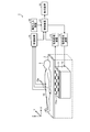
- FIG. 1 is a diagram illustrating a configuration example of a capsule endoscope system according to Embodiment 1 of the present invention.
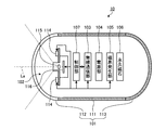
- FIG. 2 is a schematic diagram showing an example of the internal structure of the capsule endoscope according to the first embodiment of the present invention.
- FIG. 3 is a cross-sectional view showing a schematic configuration of the capsule discharge device according to Embodiment 1 of the present invention.
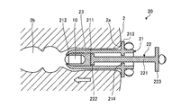
- FIG. 4A is a diagram schematically showing a process for releasing the capsule endoscope into the subject using the capsule releasing apparatus according to Embodiment 1 of the present invention.
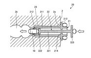
- FIG. 4B is a diagram schematically illustrating a process for releasing the capsule endoscope into the subject using the capsule discharge device according to Embodiment 1 of the present invention.
- FIG. 1 is a diagram illustrating a configuration example of a capsule endoscope system according to Embodiment 1 of the present invention.
- FIG. 2 is a schematic diagram showing an example of the internal structure of the capsule endoscope according to the first embodiment
- FIG. 4C is a diagram schematically illustrating a process for releasing the capsule endoscope into the subject using the capsule discharge device according to Embodiment 1 of the present invention.
- FIG. 5 is a cross-sectional view showing a schematic configuration of a capsule discharge device according to a modification of the first embodiment of the present invention.
- FIG. 6 is a cross-sectional view showing a schematic configuration of a capsule discharge device according to Embodiment 2 of the present invention.
- FIG. 7A is a diagram schematically showing a process for releasing a capsule endoscope into a subject using the capsule releasing apparatus according to Embodiment 2 of the present invention.
- FIG. 7B is a diagram schematically showing processing for releasing the capsule endoscope into the subject using the capsule releasing apparatus according to Embodiment 2 of the present invention.
- FIG. 7C is a diagram schematically showing a process for releasing the capsule endoscope into the subject using the capsule releasing apparatus according to Embodiment 2 of the present invention.
- FIG. 8 is a cross-sectional view showing a schematic configuration of a capsule discharge device according to a modification of the second embodiment of the present invention.
- FIG. 9A is a diagram schematically showing a process for releasing a capsule endoscope into a subject using a capsule releasing apparatus according to a modification of the second embodiment of the present invention.
- FIG. 9B is a diagram schematically showing a process for releasing the capsule endoscope into the subject using the capsule discharge device according to the modification of the second embodiment of the present invention.
- FIG. 10 is a cross-sectional view showing a schematic configuration of a capsule discharge device according to Embodiment 3 of the present invention.
- FIG. 11A is a diagram schematically showing a process for releasing a capsule endoscope into a subject using the capsule releasing apparatus according to Embodiment 3 of the present invention.
- FIG. 11B is a diagram schematically showing a process for releasing the capsule endoscope into the subject using the capsule releasing apparatus according to Embodiment 3 of the present invention.
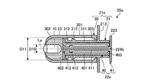
- FIG. 12 is a cross-sectional view showing a schematic configuration of a capsule discharge device according to Embodiment 4 of the present invention.
- FIG. 13 is sectional drawing which shows schematic structure of the capsule discharge
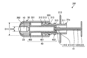
- FIG. 14 is a cross-sectional view showing a schematic configuration of a capsule discharge device according to Modification 1 of Embodiment 4 of the present invention.
- FIG. 15 is a cross-sectional view showing a schematic configuration of a capsule discharge device according to Modification 1 of Embodiment 4 of the present invention.
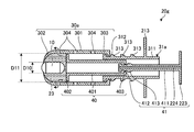
- FIG. 16 is sectional drawing which shows schematic structure of the capsule discharge
- FIG. 17 is a cross-sectional view showing a schematic configuration of a capsule discharge device according to Modification 2 of Embodiment 4 of the present invention.
- a capsule endoscope system according to an embodiment of the present invention will be described with reference to the drawings.
- a capsule endoscope that is introduced together with an isotonic solution from the anus of the subject and moves in the subject by magnetic induction is illustrated, but it moves by peristaltic movement from the esophagus to the anus of the subject.
- Various capsule endoscopes such as a capsule endoscope that images the inside of the digestive tract or a self-propelled capsule endoscope that can self-propell in the subject can be used.
- each figure has shown only the shape, magnitude
- FIG. 1 is a diagram illustrating a configuration example of a capsule endoscope system according to Embodiment 1 of the present invention.
- a capsule endoscope system 1 shown in FIG. 1 wirelessly transmits an image signal (image information) that is inserted into the large intestine of a subject 2 via a capsule release device, which will be described later, and acquired by imaging the inside of the subject 2.
- a capsule endoscope 10 that detects the position of the capsule endoscope 10 through a plurality of sense coils 11a provided below the bed 3 on which the subject 2 is placed;
- a magnetic field generator 12 that generates a magnetic field acting on the capsule endoscope 10,
- a signal processor 13 that processes a signal output from the position detector 11, and a signal for operating the magnetic field generator 12 are generated.
- the receiving device 15 that receives the image signal wirelessly transmitted from the capsule endoscope 10 via the plurality of receiving antennas 15a, and the capsule endoscope 10.
- the image signal received by the receiving device 15 a control device 17 that performs processing for displaying an image in the subject 2 (hereinafter referred to as “in-vivo image”), an in-vivo image, and the like Display device 18 for displaying the information.
- the bed 3 is arranged such that the upper surface (the surface on which the subject 2 is placed) is parallel to the horizontal surface (the surface perpendicular to the direction of gravity).
- the longitudinal direction of the bed 3 is the X direction
- the short direction of the bed 3 is the Y direction
- the vertical direction (gravity direction) is the Z direction.
- the magnetic field generator 12 functions as a magnetic field generator.
- FIG. 2 is a schematic diagram illustrating an example of the internal structure of the capsule endoscope 10.
- the capsule endoscope 10 shown in FIG. 2 captures a capsule-type casing 101 that is an exterior formed in a size that can be easily introduced into the subject 2 and an imaging that generates an image signal by imaging the subject 2.
- Unit 102 a wireless communication unit 103 that wirelessly transmits an image signal generated by the imaging unit 102 to the outside, a power supply unit 104 that supplies power to each component of the capsule endoscope 10, and a capsule endoscope
- a magnetic field generator 105 that generates an alternating magnetic field for position detection 10, a permanent magnet 106 that enables magnetic induction by the magnetic field generator 12, and a controller that controls each component of the capsule endoscope 10. 107.
- the capsule-type casing 101 is an exterior case formed to have a size that can be introduced into the organ of the subject 2 and is realized by closing both side opening ends of the cylindrical casing 111 with dome-shaped casings 112 and 113. Is done.
- the dome-shaped housing 112 is a dome-shaped optical member that is transparent to light in a predetermined wavelength band such as visible light.
- the cylindrical casing 111 and the dome-shaped casing 113 are colored casings that are substantially opaque to visible light.
- the capsule-type casing 101 formed by the cylindrical casing 111 and the dome-shaped casings 112 and 113 includes an imaging unit 102, a wireless communication unit 103, a power supply unit 104, and a magnetic field generation unit 105.
- the permanent magnet 106 and the control unit 107 are contained in a liquid-tight manner.
- the imaging unit 102 includes an illumination unit 114 such as an LED (Light Emitting Diode), an optical system 115 such as a condenser lens, and an imaging element 116 such as a CMOS (Complementary Metal Oxide Semiconductor) or a CCD (Charge Coupled Device).
- the illumination unit 114 emits illumination light such as white light to the imaging field of the imaging element 116 under the control of the control unit 107, and illuminates the subject 2 in the imaging field through the dome-shaped housing 112.
- the optical system 115 focuses the reflected light from the imaging field of view on the imaging surface of the imaging element 116 to form a subject image.
- the optical system 115 is configured using at least one lens.
- the image sensor 116 receives reflected light from the imaging field focused on the imaging surface, and photoelectrically converts the received optical signal, thereby representing an object image in the imaging field, that is, an in-vivo image of the subject 2. Generate a signal.
- the imaging unit 102 is also provided on the dome-shaped casing 113 side, and the axis La of the capsule endoscope 10 is provided. It is good also as a structure which can image the front and back of.
- the dome-shaped casing 113 is also formed by an optical member that is transparent to light of a predetermined wavelength band such as visible light.
- each optical axis is substantially parallel or substantially coincident with the axis La that is the central axis in the longitudinal direction of the capsule casing 101, and the imaging fields of view are directed in opposite directions.
- the wireless communication unit 103 sequentially wirelessly transmits the image signal generated by the imaging unit 102 to the outside via an antenna (not shown). Specifically, the wireless communication unit 103 acquires the image signal generated by the imaging unit 102 from the control unit 107, and performs signal processing such as modulation on the image signal to generate a wireless signal. The wireless communication unit 103 transmits this wireless signal to the receiving device 15 provided outside the subject 2.
- the power supply unit 104 is a power storage unit such as a button-type battery or a capacitor, and includes a magnetic switch, an optical switch, or a switch unit (not shown) that is switched by a command from the control unit 107.
- the power supply unit 104 receives a high-frequency signal having a specific pattern as a command for switching the switch unit applied from the outside, for example, via the wireless communication unit 103, and the power is turned on / off by the control of the control unit 107 based on the high-frequency signal.
- the state is switched, and the power of the power storage unit is supplied to each unit of the capsule endoscope 10 in the on state.
- the power supply part 104 stops the electric power supply to each part of the capsule endoscope 10 in an OFF state.
- the magnetic field generation unit 105 includes a transmission coil that forms a part of the resonance circuit and generates a magnetic field when a current flows, and a capacitor that forms a resonance circuit together with the transmission coil, and supplies power from the power supply unit 104. In response, an alternating magnetic field having a predetermined frequency is generated.
- the permanent magnet 106 is fixedly arranged inside the capsule endoscope 10 so that the magnetization direction has an inclination with respect to the axis La.
- the permanent magnet 106 is arranged so that the magnetization direction is orthogonal to the axis La.
- the permanent magnet 106 operates following a magnetic field applied from the outside. As a result, magnetic guidance of the capsule endoscope 10 by the magnetic field generator 12 described later is realized.
- the control unit 107 is configured using a CPU (Central Processing Unit) or the like, and controls each operation of the imaging unit 102 and the wireless communication unit 103, and also controls input / output of signals between these respective components. Specifically, every time the image sensor 116 generates an image signal, the control unit 107 acquires the image signal, performs predetermined signal processing, and further wirelessly sequentially transmits the image signal to the outside in time series.
- the wireless communication unit 103 is controlled to transmit.
- FIG. 3 is a cross-sectional view showing a schematic configuration of the capsule discharge device.
- the capsule discharge device 20 shown in FIG. 3 is used as a disposable system in a state where the capsule endoscope 10 and a lubricant are loaded.
- the capsule discharge device 20 shown in FIG. 3 accommodates the capsule endoscope 10 therein and is inserted into the large intestine of the subject 2 via the anus of the subject 2.
- the piston part 22 inserted slidably and the lubricant 23 for moving the capsule endoscope 10 smoothly are provided.
- the lubricant 23 is configured using a material applicable to a living body such as glycerin, petrolatum, gel, and lidocaine jelly.
- the cylinder part 21 has a cylinder part 211, a tip part 212, a positioning part 213, and a reduced diameter part 214.
- the cylindrical portion 211, the tip portion 212, the positioning portion 213, and the reduced diameter portion 214 are formed using an elastically deformable resin or the like. This formation may be an integral formation.
- the cylinder part 211 has a cylindrical shape.
- the cylindrical portion 211 has an inner diameter larger than the outer diameter of the capsule endoscope 10 that can be introduced into the subject.
- the cylindrical portion 211 is formed with a predetermined length so that the distal end portion 212 is disposed at a desired site of the large intestine of the subject 2.
- the distal end portion 212 is provided on the distal end side of the cylindrical portion 211 and has a tubular shape in which the inner diameter of the end portion not in contact with the cylindrical portion is equal to or smaller than the outer diameter of the capsule endoscope 10.
- the distal end portion 212 has a tubular shape that is equal to or smaller than the outer diameter of the capsule endoscope 10, and the inner diameter gradually decreases from the distal end side of the cylindrical portion 211, and the thickness of the cylindrical portion 211 increases. It gradually decreases from the tip side of the.
- the distal end portion 212 is configured to hold the capsule endoscope 10 on the inner diameter side thereof.
- the distal end portion 212 holds the longitudinal axis La of the capsule endoscope 10 and the longitudinal direction of the cylindrical portion 211 so as to coincide with each other and controls the imaging direction of the imaging unit 102 of the capsule endoscope 10.
- the sample 2 is held in the direction of insertion.
- An inner diameter D2 of the distal end portion 212 is smaller than an inner diameter D1 of the cylindrical portion 211.
- the positioning portion 213 is provided on the outer peripheral side of the proximal end side of the cylindrical portion 211 at a position having a predetermined length from the distal end portion 212, and determines the position where the capsule endoscope 10 is inserted into the subject 2. It becomes the standard.
- the predetermined length is a length set by taking into account the distance from the anus of the subject 2 to a predetermined position, for example, the colon.
- the positioning portion 213 has a flange shape, and is provided extending toward at least the outer peripheral side of the tubular portion 211 on the proximal end side of the tubular portion 211.
- the positioning portion 213 may be configured to extend not only in a flange shape but only in a part of the outer periphery, or only as a display that clearly indicates the insertion position such as a line, a symbol, a mark, or a character. It is good also as a structure which does not provide.
- the reduced diameter portion 214 is provided on the inner peripheral side of the cylindrical portion 211 corresponding to the portion where the positioning portion 213 is provided.
- the reduced diameter portion 214 has an inner diameter that is smaller than the outer diameter of the pressing portion 222 of the piston portion 22 described later and larger than the outer diameter of the insertion portion 221.
- the reduced diameter portion 214 prevents a pressing portion of the piston portion 22 described later from falling off from the cylinder portion 21.
- the piston part 22 has an insertion part 221, a pressing part 222, and an operation part 223.
- the insertion part 221, the pressing part 222, and the operation part 223 are formed of resin or the like. This formation may be an integral formation.
- the insertion part 221 has a cylindrical shape and is slidably inserted into the reduced diameter part 214 in the cylindrical part 211.
- the pressing portion 222 is provided on the distal end side of the insertion portion 221, and the outer diameter thereof is larger than the outer diameter of the insertion portion 221 and smaller than the inner diameter of the cylindrical portion 211.
- the outer diameter portion of the insertion portion 221 is formed to be slidable with respect to the inner diameter portion of the cylindrical portion 211.
- the operation unit 223 is provided on the proximal side proximal end portion of the insertion portion 221, and the outer diameter thereof is larger than the outer diameter of the insertion portion 221.
- FIG. 4A to 4C are diagrams schematically showing processing for releasing the capsule endoscope 10 into the subject 2 using the capsule releasing device 20.
- FIG. 4A to 4C are diagrams schematically showing processing for releasing the capsule endoscope 10 into the subject 2 using the capsule releasing device 20.
- the operator inserts the capsule discharge device 20 into the anus 2a of the subject 2 in a state where the capsule endoscope 10 is loaded in the cylinder portion 21 together with the lubricant 23 in advance.
- the positioning unit 213 is brought into contact with the subject 2.
- the operator needs to insert the sphincter of the anus 2a of the subject 2 with a force that overcomes the sphincter, and grasps the cylindrical portion 211 so as not to accidentally release the capsule endoscope 10 into the subject 2.
- the positioning part 213 of the cylinder part 21 is pushed toward the subject 2 and inserted into the anus 2 a of the subject 2.
- the positioning unit 213 is finally pressed against and contacted with the body wall around the anus, and the position of the capsule discharge device 20 with respect to the subject 2 can be determined.
- the surgeon further presses the operation portion 223 of the piston portion 22 in the insertion direction of the subject 2, thereby bringing the pressing portion 222 of the piston portion 22 into contact with the capsule endoscope 10 and bringing them into contact with each other.
- the capsule endoscope 10 is released from the distal end portion 212 of the cylinder portion 21 into the living body (FIG. 4B ⁇ FIG. 4C).
- the capsule endoscope 10 is arranged at a desired position of the large intestine 2b of the subject 2.
- the lubricant 23 is also released together with the capsule endoscope 10 by the movement of the piston portion 22, the capsule endoscope 10 can be smoothly inserted into the living body.
- the lubricant 23 may be applied to the surface of the cylinder portion 21. Thereby, the capsule discharge device 20 can be more easily inserted into the subject 2.
- the capsule endoscope 10 can be easily placed at a desired position in the large intestine 2b of the subject 2. Can be easily inserted by operation.
- the distal end portion 212 holds the capsule endoscope 10 with the longitudinal direction of the capsule endoscope 10 aligned with the longitudinal direction of the cylindrical portion 211, and the imaging of the capsule endoscope 10. Since the side is held in the direction in which the subject 2 is inserted, insertion can be performed while viewing the image transmitted from the capsule endoscope 10 when the capsule endoscope 10 is inserted.
- the lubricant 23 is accommodated in the capsule discharge device 20, when the capsule endoscope 10 is inserted into the subject 2, it can be smoothly inserted. .
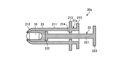
- FIG. 5 is a cross-sectional view showing a schematic configuration of a capsule discharge device according to a modification of the first embodiment of the present invention.
- a capsule discharge device 20a shown in FIG. 5 includes a cylinder part 21a that houses the capsule endoscope 10 and is inserted into the large intestine 2b of the subject 2 through the anus of the subject 2, a piston part 22, And a lubricant 23.
- the cylinder part 21a includes a cylinder part 211, a tip part 212, a positioning part 213, a reduced diameter part 214, and a flange part 215.
- the flange portion 215 is provided to extend toward the outer peripheral side on the proximal end side of the cylindrical portion 211.
- the tube portion 211, the tip portion 212, the positioning portion 213, the reduced diameter portion 214, and the flange portion 215 are integrally formed.
- the operator can take a gripping position like a syringe by placing a finger between the flange portion 215 and the positioning portion 213.
- the operation of the piston portion 22 can be easily performed.
- the release operation of the capsule endoscope 10 can be easily performed with a simple operation.
- the capsule discharge device according to the second embodiment is different in configuration from the capsule discharge device 20 according to the first embodiment described above. For this reason, below, the structure of the capsule discharge
- symbol is attached
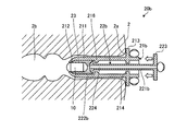
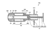
- FIG. 6 is a cross-sectional view showing a schematic configuration of a capsule discharge device according to Embodiment 2 of the present invention.
- the capsule discharge device 20b shown in FIG. 6 accommodates the capsule endoscope 10 therein and is inserted into the large intestine of the subject 2 through the anus of the subject 2, and the cylinder portion 21b.
- the piston part 22b inserted slidably and the lubricant 23 are provided.
- the cylinder part 21b includes a cylinder part 211, a tip part 212, a positioning part 213, a reduced diameter part 214, and a claw part 216.
- claw part 216 is provided in the inner peripheral side of the cylinder part 211, and the internal diameter is smaller than the outer diameter of the press part 222b mentioned later.
- the claw portion 216 is formed using an elastically deformable member.
- the claw portion 216 is formed to be inclined so that the inner diameter gradually increases from the tip side.
- the claw portion 216 prevents the piston portion 22b from entering, and when pressed by the piston portion 22b, at least one of the pressing portion 222b or the claw portion 216 described later is elastically deformed.
- the claw portion 216 is provided on the entire inner circumference side of the cylindrical portion 211, but may be configured to be provided on a part of the inner circumferential side of the cylindrical portion 211.
- the piston portion 22b is slidably inserted into the cylindrical portion 211, and is provided at the distal end side of the insertion portion 221b, with an insertion portion 221b in which a space 224 is formed, A pressing portion 222b having an outer diameter smaller than the inner diameter of the cylindrical portion 211 and an operation portion 223 are provided.
- the space 224 is formed so as to penetrate the longitudinal direction of the insertion portion 221b.
- the pressing portion 222 b is formed in a tapered shape so that the diameter gradually increases from the distal end toward the proximal end side, and the maximum outer diameter is larger than the minimum inner diameter of the claw portion 216.
- the lubricant 23 is filled on the tip side of the claw portion 216.
- FIGS. 7A to 7C are diagrams schematically showing a process for releasing the capsule endoscope 10 into the subject 2 using the capsule discharge device 20b.
- the operator inserts the capsule discharge device 20b into the anus 2a of the subject 2 in a state where the capsule endoscope 10 and the lubricant 23 are loaded in the cylinder portion 21b in advance.
- the positioning unit 213 is brought into contact with the subject 2. In this case, it is necessary for the operator to insert the sphincter of the anus 2a of the subject 2 with a force that overcomes the sphincter, and while grasping the positioning unit 213 so as not to accidentally release the capsule endoscope 10 into the subject 2. Insert into the anus 2a of the subject 2. Thereby, the position of the capsule discharge device 20b with respect to the subject 2 is determined.
- the surgeon pushes the operating portion 223 of the piston portion 22b strongly in the insertion direction of the subject 2 to get over the pressing portion 222b of the piston portion 22b over the claw portion 216 of the cylinder portion 21b (FIG. 7A). ⁇ FIG. 7B).
- the pressing portion 222b of the piston portion 22b is elastically deformed so as to shrink toward the center in the radial direction, thereby moving over the claw portion 216 and moving to the position on the tip end portion 212 side. That is, in order to get over the claw portion 216, it is necessary to press the operation portion 223 by applying a large force, so that the piston portion 22b may be accidentally pressed during transport of the capsule discharge device 20b.
- the capsule endoscope 10 can be prevented from being released at an undesired location.
- the surgeon further presses the operation portion 223 of the piston portion 22b in the insertion direction of the subject 2, thereby bringing the pressing portion 222b of the piston portion 22b into contact with the capsule endoscope 10 and in contact with the capsule endoscope 10.
- the capsule endoscope 10 is released from the distal end portion 212 of the cylinder portion 21b into the living body (FIG. 7B ⁇ FIG. 7C).
- the capsule endoscope 10 is arranged at a desired position of the large intestine 2b of the subject 2.
- the capsule endoscope 10 is erroneously not desired when transporting the capsule discharge device 20b. It can be prevented from being released.
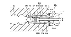
- FIG. 8 is a cross-sectional view showing a schematic configuration of a capsule releasing apparatus according to a modification of the second embodiment of the present invention. 8 includes a cylinder portion 21b, a piston portion 22b, and a support member 24 that holds the capsule endoscope 10.
- the support member 24 maintains the position of the capsule endoscope 10 in the cylinder portion 21b.
- the support member 24 prevents the capsule endoscope 10 from dropping into the cylinder portion 21b even when an external force is applied from the digestive tract or the like when the capsule discharge device 20c is inserted into the subject 2.
- the support member 24 has a columnar shape, and a groove portion that supports the capsule endoscope 10 therein is provided on the distal end side.
- the support member 24 is formed using, for example, a sponge. Further, the support member 24 prevents damage caused by the capsule endoscope 10 coming into contact with the pressing portion 222b of the piston portion 22b. Further, the support member 24 is disposed inside the cylinder portion 21b in a state of being in contact with the claw portion 216.
- FIG. 9A and FIG. 9B are diagrams schematically showing processing for releasing the capsule endoscope 10 into the subject 2 using the capsule releasing device 20c.
- the operator inserts the capsule discharge device 20c into the anus 2a of the subject 2 in a state where the capsule endoscope 10 is loaded together with the support member 24 in the cylinder portion 21b in advance.
- the positioning unit 213 is brought into contact with the subject 2.
- the support member 24 supports the capsule endoscope 10 even when an external force is applied from the sphincter of the anus 2a of the subject 2. Thereby, it is possible to prevent the capsule endoscope 10 from falling into the cylinder portion 21b.
- the surgeon strongly pushes the operation portion 223 of the piston portion 22b in the insertion direction of the subject 2, thereby getting over the pressing portion 222b of the piston portion 22b with respect to the claw portion 216 of the cylinder portion 21b.
- the pressing part 222b of 22b is brought into contact with the support member 24, and the capsule part 10 is further released from the tip part 212 of the cylinder part 21b by further pushing the piston part 22b in the contacted state (FIG. 9A). ⁇ FIG. 9B).
- the capsule endoscope 10 is arranged at a desired position of the large intestine 2b of the subject 2.
- the capsule endoscope 10 is provided with the cylinder portion. It is possible to prevent falling into 21b.
- the lubricant 23 may be loaded between the cylinder portion 21b and the capsule endoscope 10.
- the capsule discharge device according to the third embodiment is different in configuration from the capsule discharge device 20b according to the second embodiment described above. Therefore, the configuration of the capsule discharge device according to the third embodiment will be described below.
- symbol is attached
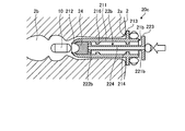
- FIG. 10 is a cross-sectional view showing a schematic configuration of a capsule discharge device according to Embodiment 3 of the present invention.
- a capsule release device 20d shown in FIG. 10 includes a cylinder part 21d that accommodates the capsule endoscope 10 therein and is inserted into the large intestine of the subject 2 through the anus of the subject 2, and a piston part 22b.
- the lubricant 23 may be disposed in the cylinder portion 21d.
- the cylinder part 21d includes a cylinder part 211, a tip part 212, a positioning part 213, a reduced diameter part 214, and a holding state releasing part 400.
- the holding state release unit 400 releases the state in which the distal end portion 212 holds the capsule endoscope 10 by the operation of inserting the insertion portion 221b.
- the holding state release unit 400 includes a claw portion 216 and a groove portion 217.
- the groove portion 217 is provided by forming a groove on the outer peripheral side of the cylindrical portion 211 so as to go around the center of the cylindrical portion 211.
- the thickness dimension of the cylinder part 211 in the groove part 217 is smaller than the thickness dimension of the other part of the cylinder part 211.
- the groove portion 217 is provided on the outer peripheral side of the cylindrical portion 211 corresponding to the portion where the claw portion 216 is provided.
- FIG. 11A and FIG. 11B are diagrams schematically showing processing for releasing the capsule endoscope 10 into the subject 2 using the capsule discharge device 20d.
- the operator inserts the capsule discharge device 20d into the anus 2a of the subject 2 with the capsule endoscope 10 loaded in the cylinder portion 21d, and covers the positioning portion 213. Contact with the specimen 2.
- the capsule endoscope 10 is previously held by the distal end portion 212.
- the operator presses the pressing portion 222b of the piston portion 22b against the claw portion 216 of the cylinder portion 21d by strongly pressing the operation portion 223 of the piston portion 22b in the insertion direction of the subject 2.
- the inclined surface of the pressing portion 222b of the piston portion 22b presses the inclined surface of the claw portion 216.
- a force that pushes the distal end portion 212 toward the outer edge side acts on the distal end portion 212 of the cylinder portion 21d, so that the distal end portion 212 spreads to the outer peripheral side with respect to the groove portion 217, and the capsule endoscope 10 is released.
- FIG. 11A ⁇ FIG. 11B As a result, the capsule endoscope 10 is placed at a desired position on the large intestine 2b of the subject 2.
- the capsule endoscope 10 can be easily inserted into the large intestine 2b of the subject 2 by a simple operation.
- the capsule discharge device according to the fourth embodiment is different in configuration from the capsule discharge devices according to the first to third embodiments described above. Specifically, the capsule discharge device according to the fourth embodiment has a shape that can be expanded and contracted. For this reason, below, the structure of the capsule discharge
- symbol is attached
- FIG. 12 is a cross-sectional view showing a schematic configuration of the capsule discharge device according to Embodiment 4 of the present invention, and is a cross-sectional view showing a contracted state.
- FIG. 13 is sectional drawing which shows schematic structure of the capsule discharge
- a cylinder part 21e that accommodates the capsule endoscope 10 therein and is inserted into the large intestine of the subject 2 through the anus of the subject 2, and a cylinder part 21e. And a piston portion 22e slidably inserted.
- the cylinder portion 21e includes a cylindrical first cylindrical member 30 and a second cylindrical member 31 that is slidably disposed inside the first cylindrical member 30 and has a cylindrical shape.
- the first cylindrical member 30 has a cylindrical first cylindrical portion 301 and an inner diameter that gradually decreases from the distal end side of the first cylindrical portion 301 (D11 ⁇ D10), and the thickness of the first cylindrical member 30 And a distal end portion 302 that is smaller in outer diameter than the outer diameter of the capsule endoscope 10 and can be elastically deformed, and a proximal end side of the first cylindrical portion 301 from the inner peripheral side. And an annular reduced diameter portion 303 provided extending toward the center. The distal end 302 side of the reduced diameter portion 303 is an inclined surface.
- the second cylindrical member 31 includes a cylindrical second cylindrical portion 311, a first convex portion 312 and a second convex portion 313 provided to extend toward the outer circumference in the radial direction of the second cylindrical portion 311. And having.
- the second convex portion 313 gradually decreases in diameter toward the proximal end side of the second cylindrical member 31 and forms an inclined surface.
- the first convex portion 312 and the second convex portion 313 are engaged with the reduced diameter portion 303 of the first cylindrical member 30 to extend the second cylindrical member 31 from the first cylindrical member 30. It functions as a first stopper for maintaining.
- the piston portion 22e includes a cylindrical first insertion member 40 and a second insertion member 41 that is slidably disposed inside the first insertion member 40 and has a cylindrical shape.
- the first insertion member 40 includes a cylindrical first insertion member 401 that is slidably inserted into the second cylindrical portion 311, and an inner diameter of the first cylindrical portion 301 that is larger than the outer diameter of the first insertion member 401.
- the third convex portion 403 is formed such that the diameter gradually decreases from the proximal end side to the distal end side of the first insertion member 40, and has an inclined surface.
- the second insertion member 41 includes a cylindrical second insertion portion 411, a fourth convex portion 412 that is larger than the outer diameter of the second insertion portion 411 and smaller than the inner diameter of the third convex portion 403, and a fifth convex portion 413. It has the operation part 223 provided in the base end side of the 2nd insertion part 411, and the through-hole 224b penetrated in the longitudinal direction of a 2nd insertion member.
- the 5th convex part 413 is formed so that a diameter may become small gradually toward the base end side of the 2nd insertion part 411, and has an inclined surface.
- the 4th convex part 412 and the 5th convex part 413 maintain the state which extended the 2nd insertion member 41 from the 1st insertion member 40 by fitting with the 3rd convex part 403 of the 1st insertion member 40. It functions as a second stopper portion for this purpose.
- the surgeon extends the second cylindrical member 31 from the first cylindrical member 30, whereby the first convex portion 312 and the second convex portion 313 are moved to the first. It fits in the reduced diameter part 303 of the cylindrical member 30.
- the capsule releasing device 20e is configured such that the operator extends the second insertion member 41 from the first insertion member 40, thereby changing the fourth protrusion 412 and the fifth protrusion 413 to the third protrusion of the first insertion member 40. 403 is fitted (see FIG. 12 ⁇ FIG. 13).
- the capsule endoscope can be placed at a desired position of the large intestine of the subject by performing the same operation as in the above-described embodiments.
- the capsule discharge device 20e can be downsized.
- the claw portion 216 of the second embodiment described above may be provided on the inner peripheral side of the second cylindrical member 31. Thereby, it is possible to prevent the capsule endoscope from being accidentally released at an undesired location when the capsule releasing device 20e is transported.
- Modification 1 of Embodiment 4 Modification 1 of Embodiment 4 of the present invention will be described.
- Modification 1 according to the fourth embodiment is different in the configuration of the cylinder portion 21e in the capsule discharge device 20e of the fourth embodiment described above. For this reason, below, the structure of the capsule discharge
- symbol is attached
- FIG. 14 is a cross-sectional view showing a schematic configuration of a capsule discharge device according to Modification 1 of Embodiment 4 of the present invention, and is a cross-sectional view showing a contracted state.
- FIG. 15 is sectional drawing which shows schematic structure of the capsule discharge device which concerns on the modification 1 of Embodiment 4 of this invention, and is sectional drawing which shows an expansion
- the second cylindrical member 31a includes a second cylindrical portion 311, a first convex portion 312, and a plurality of second convex portions 313.
- the plurality of second convex portions 313 are provided at predetermined equal intervals from the distal end side of the second cylindrical member 31a.
- the surgeon extends the second cylindrical member 31a from the first cylindrical member 30, whereby the first convex portion 312 and the second convex portion 313 are moved to the first. It fits in the reduced diameter part 303 of the cylindrical member 30.
- the surgeon changes the position of the second convex portion 313 to be fitted to the reduced diameter portion 303 of the first cylindrical member 30 according to the subject 2.
- the length of the capsule discharge device 20f can be changed and extended according to the subject 2.
- the insertion length of the capsule discharge device 20f can be changed in accordance with the subject 2, and the size can be reduced during storage.
- the claw portion of the second embodiment described above may be provided on the inner peripheral side of the second cylindrical member 31a.
- FIG. 16 is a cross-sectional view showing a schematic configuration of a capsule discharge device according to Modification 2 of Embodiment 4 of the present invention, and is a cross-sectional view showing a contracted state.
- FIG. 17 is sectional drawing which shows schematic structure of the capsule discharge
- the 16 has a first cylindrical member 30a in place of the first cylindrical member 30 of the capsule discharging apparatus 20f according to Modification 1 of Embodiment 4 described above.
- the first cylindrical member 30a is provided with a plurality of holes 304 that communicate the inner peripheral side and the outer peripheral side at predetermined intervals.
- the hole 304 is provided with two or more by the 1st cylindrical member 30a, only the front end side of the 1st cylindrical member 30a may be sufficient.
- the capsule discharge device 20g configured as described above, when the piston portion 22e is inserted into the cylinder portion 21g, the lubricant 23 stored in the cylinder portion 21g is discharged to the outside through the hole 304. As a result, the capsule discharge device 20g can be inserted into the subject 2 more smoothly than when the lubricant 23 is discharged from the distal end portion 302.
- the lubricant 23 is introduced from the hole 304 into the subject 2 by providing the first cylindrical member 30a with the plurality of holes 304 connected to the outside. Since the discharge is performed, the capsule discharge device 20g can be inserted into the subject 2 more smoothly than when the lubricant 23 is discharged from the distal end portion 302.
- a cushioning material such as sponge or rubber may be further provided on the pressing portion of the piston portion. Thereby, it is possible to prevent the capsule endoscope from being damaged by the sliding operation of the piston portion.
- a non-slip structure for example, a groove or a taper shape may be provided on the outer periphery of the operation portion of the piston portion.
- the present invention is not limited to the above-described embodiments as they are, and in the implementation stage, the constituent elements can be modified and embodied without departing from the gist of the invention.
- Various inventions can be formed by appropriately combining a plurality of constituent elements disclosed in the above-described embodiments. For example, some constituent elements may be deleted from all the constituent elements described in the above-described embodiments without departing from the gist of the present invention. Furthermore, the constituent elements described in the embodiments may be combined as appropriate.
Landscapes
- Health & Medical Sciences (AREA)
- Life Sciences & Earth Sciences (AREA)
- Surgery (AREA)
- Nuclear Medicine, Radiotherapy & Molecular Imaging (AREA)
- Biomedical Technology (AREA)
- Optics & Photonics (AREA)
- Pathology (AREA)
- Radiology & Medical Imaging (AREA)
- Biophysics (AREA)
- Engineering & Computer Science (AREA)
- Physics & Mathematics (AREA)
- Heart & Thoracic Surgery (AREA)
- Medical Informatics (AREA)
- Molecular Biology (AREA)
- Animal Behavior & Ethology (AREA)
- General Health & Medical Sciences (AREA)
- Public Health (AREA)
- Veterinary Medicine (AREA)
- Endoscopes (AREA)
Abstract
カプセル型内視鏡を大腸内に簡易な操作で正確に配置することができるカプセル放出装置およびカプセル放出システムを提供する。カプセル放出装置20は、筒部211の先端側に設けられ、筒部211に接していない側の端部の内径がカプセル型内視鏡10の外径以下である管状をなす先端部212と、筒部211の基端側の外周側に設けられ、被検体に対してカプセル型内視鏡10を挿入する位置を決めるための位置決め部213と、を有するシリンダ部21と、筒部211内に対して摺動可能に挿入される挿入部221と、挿入部221の先端側に設けられ、外径が挿入部221の外径より大きく、かつ筒部211の内径より小さい押圧部222と、挿入部221の基端側に設けられ、挿入部221の外径より大きい操作部223と、を有するピストン部22と、を備える。
Description
本発明は、カプセル型内視鏡を放出して被検体内に挿入するカプセル放出装置およびカプセル放出システムに関する。
従来、カプセル型内視鏡は、経口摂取するため、被検体の口から大腸に達するまで、かなりの時間を要する。このため、従来においては、カプセル型内視鏡を被検体の肛門から挿入して大腸を観察する技術が知られている(特許文献1参照)。この技術では、内視鏡を介して、カプセル型内視鏡を把持するガイドワイヤを被検体の肛門に挿入することによって、カプセル型内視鏡を被検体の大腸内に挿入する。
しかしながら、上述した特許文献1では、内視鏡を介してカプセル型内視鏡を被検体内に挿入して配置するので、被検体に対するカプセル型内視鏡の位置決めを正確に行うことが難しかった。また、上述した特許文献1では、カプセル型内視鏡を被検体内に挿入するために必要な器具も多いため、作業が煩雑になるという問題点があった。
本発明は、上記に鑑みてなされたものであって、カプセル型内視鏡を大腸内に簡易な操作で正確に配置することができるカプセル放出装置およびカプセル放出システムを提供することを目的とする。
上述した課題を解決し、目的を達成するために、本発明に係るカプセル放出装置は、被検体に導入可能なカプセル型内視鏡の外径より内径が大きい筒状をなす筒部と、前記筒部の先端側に設けられ、前記筒部に接していない側の端部の内径が前記カプセル型内視鏡の外径以下である管状をなす先端部と、前記先端部から所定の距離の前記筒部における基端側の外周側に設けられ、前記被検体に対して前記カプセル型内視鏡を挿入する位置を決めるための位置決め部と、を有するシリンダ部と、前記筒部内に対して摺動可能に挿入される挿入部と、前記カプセル型内視鏡を前記先端部側へ押圧する押圧部と、前記挿入部の基端側に設けられ、操作者が把持して前記押圧部を前記先端側へ押し込むための操作部と、を有するピストン部と、を備えたことを特徴とする。
また、本発明に係るカプセル放出装置は、上記発明において、前記先端部は、前記筒部の先端側から徐々に内径が小さくなるとともに、肉厚方向の厚さが前記筒部の先端側から徐々に減少し、前記操作部は、前記挿入部の外径より大きいことを特徴とする。
また、本発明に係るカプセル放出装置は、上記発明において、前記位置決め部は、前記筒部の基端側において少なくとも一部が前記筒部の外周側に向けて延在して設けられていることを特徴とする。
また、本発明に係るカプセル放出装置は、上記発明において、前記カプセル型内視鏡は、前記被検体を撮像する撮像部を有し、前記先端部は、前記カプセル型内視鏡の長手方向と前記筒部の長手方向とを一致させて保持するとともに、前記撮像部の撮像方向を前記被検体の挿入方向に向けて保持することを特徴とする。
また、本発明に係るカプセル放出装置は、上記発明において、前記先端部と前記カプセル型内視鏡の間に配置された潤滑剤をさらに備えたことを特徴とする。
また、本発明に係るカプセル放出装置は、上記発明において、前記筒部の内周側に設けられる縮径部をさらに備え、前記押圧部は、外径が前記挿入部の外径より大きく、かつ前記筒部の内径より小さく、前記縮径部は、内径が前記押圧部の外径より小さく、かつ、前記挿入部の外径より大きいことを特徴とする。
また、本発明に係るカプセル放出装置は、上記発明において、前記筒部の内周側に設けられ、前記押圧部の外径より小さく、前記筒部の先端側から徐々に内径が大きくなるように傾斜して形成され、弾性変形可能な爪部をさらに備え、前記爪部は、前記押圧部が当接して前記押圧部または当該爪部の少なくとも一方が弾性変形して前記押圧部を通過させ、前記押圧部は、前記爪部を通過した後に、前記カプセル型内視鏡に押圧することを特徴とする。
また、本発明に係るカプセル放出装置は、上記発明において、前記爪部と前記先端部の間に配置され、前記カプセル型内視鏡を軸方向に支持する支持部材をさらに備えたことを特徴とする。
また、本発明に係るカプセル放出装置は、上記発明において、前記挿入部が挿入される操作により前記先端部が前記カプセル型内視鏡を保持している状態を解除する保持状態解除部をさらに備えたことを特徴とする。
また、本発明に係るカプセル放出装置は、上記発明において、前記保持状態解除部は、前記筒部の内周側に設けられ、前記先端部の外径より小さく、前記筒部の先端側から徐々に内径が大きくなるように傾斜して形成された爪部と、前記爪部が設けられた部分に対応する前記筒部の外周側に設けられた溝部と、を有することを特徴とする。
また、本発明に係るカプセル放出装置は、上記発明において、前記筒部は、筒状をなす第1筒状部材と、前記第1筒状部材の内部に収容され、前記第1筒状部材に対して摺動可能な第2筒状部材と、前記第1筒状部材から前記第2筒状部材を伸長させた状態を維持する第1ストッパ部と、を有し、前記挿入部は、筒状をなす第1挿入部材と、前記第1挿入部材の内部に収容され、前記第1挿入部材に対して摺動可能な第2挿入部材と、前記第1挿入部材から前記第2挿入部材を伸長させた状態を維持する第2ストッパ部と、を有することを特徴とする。
また、本発明に係るカプセル放出装置は、上記発明において、前記第1ストッパ部は、前記第2筒状部材の外周側に所定の間隔で複数設けられていることを特徴とする。
また、本発明に係るカプセル放出装置は、上記発明において、前記第1筒状部材は、内周側と外周側とを連通する複数の孔が設けられていることを特徴とする。
また、本発明に係るカプセル放出システムは、上記のカプセル放出装置と、前記カプセル型内視鏡と、を備えたことを特徴とする。
本発明によれば、カプセル型内視鏡を大腸内に簡易な操作で正確に挿入することができるという効果を奏する。
以下、本発明の実施の形態に係るカプセル型内視鏡システムについて、図面を参照しながら説明する。なお、以下の説明においては被検体の肛門から等張液とともに導入されて磁気誘導によって被検体内を移動するカプセル型内視鏡を例示するが、被検体の食道から肛門にかけて蠕動運動により移動しつつ消化管内を撮像するカプセル型内視鏡または被検体内を自走可能な自走式のカプセル型内視鏡など、種々のカプセル型内視鏡を用いることが可能である。また、以下の説明において、各図は本発明の内容を理解でき得る程度に形状、大きさ、および位置関係を概略的に示してあるに過ぎない。従って、本発明は各図で例示された形状、大きさ、および位置関係のみに限定されるものではない。なお、図面の記載において、同一部分には同一の符号を付している。
(実施の形態1)
〔カプセル型内視鏡システムの構成〕
図1は、本発明の実施の形態1に係るカプセル型内視鏡システムの構成例を示す図である。図1に示すカプセル型内視鏡システム1は、後述するカプセル放出装置を介して被検体2の大腸に挿入され、被検体2内を撮像することにより取得した画像信号(画像情報)を無線送信するカプセル型内視鏡10と、被検体2が載置されるベッド3の下方に設けられた複数のセンスコイル11aを介してカプセル型内視鏡10の位置を検出する位置検出装置11と、カプセル型内視鏡10に作用する磁界を発生する磁界発生装置12と、位置検出装置11から出力された信号を処理する信号処理装置13と、磁界発生装置12を動作させるための信号を発生する信号発生装置14と、複数の受信アンテナ15aを介してカプセル型内視鏡10から無線送信された画像信号を受信する受信装置15と、カプセル型内視鏡10を誘導操作するための操作入力装置16と、受信装置15が受信した画像信号に基づいて、被検体2内の画像(以下、「体内画像」という)を表示するための処理を行う制御装置17と、体内画像やその他の情報を表示する表示装置18と、を備える。なお、ベッド3は、上面(被検体2の載置面)が水平面(重力方向の直交面)と平行になるように配置されている。以下においては、ベッド3の長手方向をX方向、ベッド3の短手方向をY方向、鉛直方向(重力方向)をZ方向とする。また、本実施の形態1では、磁界発生装置12が磁界発生部として機能する。
〔カプセル型内視鏡システムの構成〕
図1は、本発明の実施の形態1に係るカプセル型内視鏡システムの構成例を示す図である。図1に示すカプセル型内視鏡システム1は、後述するカプセル放出装置を介して被検体2の大腸に挿入され、被検体2内を撮像することにより取得した画像信号(画像情報)を無線送信するカプセル型内視鏡10と、被検体2が載置されるベッド3の下方に設けられた複数のセンスコイル11aを介してカプセル型内視鏡10の位置を検出する位置検出装置11と、カプセル型内視鏡10に作用する磁界を発生する磁界発生装置12と、位置検出装置11から出力された信号を処理する信号処理装置13と、磁界発生装置12を動作させるための信号を発生する信号発生装置14と、複数の受信アンテナ15aを介してカプセル型内視鏡10から無線送信された画像信号を受信する受信装置15と、カプセル型内視鏡10を誘導操作するための操作入力装置16と、受信装置15が受信した画像信号に基づいて、被検体2内の画像(以下、「体内画像」という)を表示するための処理を行う制御装置17と、体内画像やその他の情報を表示する表示装置18と、を備える。なお、ベッド3は、上面(被検体2の載置面)が水平面(重力方向の直交面)と平行になるように配置されている。以下においては、ベッド3の長手方向をX方向、ベッド3の短手方向をY方向、鉛直方向(重力方向)をZ方向とする。また、本実施の形態1では、磁界発生装置12が磁界発生部として機能する。
〔カプセル型内視鏡の構成〕
次に、カプセル型内視鏡10の構成について説明する。図2は、カプセル型内視鏡10の内部構造の一例を示す模式図である。図2に示すカプセル型内視鏡10は、被検体2の内部に導入し易い大きさに形成された外装であるカプセル型筐体101と、被検体2を撮像して画像信号を生成する撮像部102と、撮像部102によって生成された画像信号を外部に無線送信する無線通信部103と、カプセル型内視鏡10の各構成部に電力を供給する電源部104と、カプセル型内視鏡10の位置検出用の交番磁界を発生する磁界発生部105と、磁界発生装置12による磁気誘導を可能にするための永久磁石106と、カプセル型内視鏡10の各構成部を制御する制御部107と、を備える。
次に、カプセル型内視鏡10の構成について説明する。図2は、カプセル型内視鏡10の内部構造の一例を示す模式図である。図2に示すカプセル型内視鏡10は、被検体2の内部に導入し易い大きさに形成された外装であるカプセル型筐体101と、被検体2を撮像して画像信号を生成する撮像部102と、撮像部102によって生成された画像信号を外部に無線送信する無線通信部103と、カプセル型内視鏡10の各構成部に電力を供給する電源部104と、カプセル型内視鏡10の位置検出用の交番磁界を発生する磁界発生部105と、磁界発生装置12による磁気誘導を可能にするための永久磁石106と、カプセル型内視鏡10の各構成部を制御する制御部107と、を備える。
カプセル型筐体101は、被検体2の臓器内部に導入可能な大きさに形成された外装ケースであり、筒状筐体111の両側開口端をドーム形状筐体112,113によって塞ぐことによって実現される。ドーム形状筐体112は、可視光等の所定波長帯域の光に対して透明なドーム形状の光学部材である。また、筒状筐体111およびドーム形状筐体113は、可視光に対して略不透明な有色の筐体である。これらの筒状筐体111およびドーム形状筐体112,113によって形成されるカプセル型筐体101は、図2に示すように、撮像部102、無線通信部103、電源部104、磁界発生部105、永久磁石106および制御部107、を液密に内包する。
撮像部102は、LED(Light Emitting Diode)等の照明部114と、集光レンズ等の光学系115と、CMOS(Complementary Metal Oxide Semiconductor)またはCCD(Charge Coupled Device)等の撮像素子116と、を有する。照明部114は、制御部107の制御のもと、撮像素子116の撮像視野に白色光等の照明光を発光して、ドーム形状筐体112越しに撮像視野内の被検体2を照明する。光学系115は、撮像視野からの反射光を撮像素子116の撮像面に集光して被検体像を結像させる。光学系115は、少なくとも1以上のレンズを用いて構成される。撮像素子116は、撮像面に集光された撮像視野からの反射光を受光し、受光した光信号を光電変換することにより、撮像視野の被検体像、即ち被検体2の体内画像を表す画像信号を生成する。
なお、本実施の形態においては、カプセル型内視鏡10に撮像部102を1つのみ設けたが、ドーム形状筐体113側にも撮像部102を設け、カプセル型内視鏡10の軸Laの前方および後方を撮像可能な構成としても良い。この場合、ドーム形状筐体113も可視光等の所定波長帯域の光に対して透明な光学部材によって形成する。また、この場合、2つの撮像部102は、各々の光軸がカプセル型筐体101の長手方向の中心軸である軸Laと略平行または略一致し、且つ各撮像視野が互いに反対方向を向くように配置される。
無線通信部103は、撮像部102が生成した画像信号を、図示しないアンテナを介して外部に順次無線送信する。具体的には、無線通信部103は、撮像部102が生成した画像信号を制御部107から取得し、この画像信号に変調等の信号処理を施して無線信号を生成する。無線通信部103は、この無線信号を、被検体2外に設けられた受信装置15に送信する。
電源部104は、ボタン型電池またはキャパシタ等の蓄電部であって、磁気スイッチや光スイッチ、あるいは制御部107からのコマンドによって切り替えられるスイッチ部(図示せず)を有する。電源部104は、例えば無線通信部103を介して外部から印加されたスイッチ部を切り替えるコマンドとなる特定のパターンの高周波信号を受信すると共に、この高周波信号に基づく制御部107の制御によって電源のオンオフ状態を切り替え、オン状態の場合に、蓄電部の電力をカプセル型内視鏡10の各部に供給する。また、電源部104は、オフ状態の場合に、カプセル型内視鏡10の各部への電力供給を停止する。
磁界発生部105は、共振回路の一部をなし、電流が流れることにより磁界を発生する送信コイルと、この送信コイルと共に共振回路を形成するコンデンサと、を含み、電源部104からの電力供給を受けて所定の周波数の交番磁界を発生する。
永久磁石106は、磁化方向が軸Laに対して傾きを持つように、カプセル型内視鏡10の内部に固定配置される。本実施の形態1において、永久磁石106は、磁化方向が軸Laに対して直交するように配置されている。永久磁石106は、外部から印加された磁界に追従して動作し、この結果、後述する磁界発生装置12によるカプセル型内視鏡10の磁気誘導が実現する。
制御部107は、CPU(Central Processing Unit)等を用いて構成され、撮像部102および無線通信部103の各動作を制御すると共に、これらの各構成部間における信号の入出力を制御する。具体的には、制御部107は、撮像素子116が画像信号を生成する都度、この画像信号を取得して所定の信号処理を施し、さらに、この画像信号を時系列に沿って外部に順次無線送信するように無線通信部103を制御する。
〔カプセル放出装置の構成〕
次に、カプセル型内視鏡10を被検体2の内部に挿入して放出するためのカプセル放出装置の構成について説明する。図3は、カプセル放出装置の概略構成を示す断面図である。図3に示すカプセル放出装置20は、カプセル型内視鏡10および潤滑剤が装填された状態でディスポーザブル型のシステムとして使用される。
次に、カプセル型内視鏡10を被検体2の内部に挿入して放出するためのカプセル放出装置の構成について説明する。図3は、カプセル放出装置の概略構成を示す断面図である。図3に示すカプセル放出装置20は、カプセル型内視鏡10および潤滑剤が装填された状態でディスポーザブル型のシステムとして使用される。
図3に示すカプセル放出装置20は、カプセル型内視鏡10を内部に収容して被検体2の肛門を介して被検体2の大腸へ挿入されるシリンダ部21と、シリンダ部21に対して摺動可能に挿入されたピストン部22と、カプセル型内視鏡10をなめらかに移動させるための潤滑剤23と、を備える。潤滑剤23は、例えばグリセリン、ワセリン、ジェルおよびリドカインゼリー等の生体に適用可能なものを用いて構成される。
シリンダ部21は、筒部211と、先端部212と、位置決め部213と、縮径部214と、有する。筒部211、先端部212、位置決め部213および縮径部214は、弾性変形可能な樹脂等を用いて形成される。なお、この形成は、一体的な形成であってもよい。
筒部211は、筒状をなす。筒部211は、被検体に導入可能なカプセル型内視鏡10の外径より内径が大きい。筒部211は、先端部212が被検体2の大腸の所望の部位に配置されるようにその長さが予め規定されて形成される。
先端部212は、筒部211の先端側に設けられ、筒部に接していない側の端部の内径がカプセル型内視鏡10の外径以下である管状をなす。具体的には、先端部212の最先端は、カプセル型内視鏡10の外径以下となる管状をなし、筒部211の先端側から徐々に内径が小さくなるとともに、肉厚が筒部211の先端側から徐々に減少する。先端部212は、その内径側にカプセル型内視鏡10を保持するよう構成される。また、先端部212は、カプセル型内視鏡10の長手方向の軸Laと筒部211の長手方向とを一致させて保持するとともに、カプセル型内視鏡10の撮像部102の撮像方向を被検体2の挿入方向に向けて保持する。先端部212の内径D2は、筒部211の内径D1より小さい。
位置決め部213は、先端部212から所定の長さを有する位置における筒部211の基端側の外周側に設けられ、被検体2に対してカプセル型内視鏡10を挿入する位置を決めるための基準となる。ここで、上記所定の長さとは、被検体2の肛門から所定の位置、例えば結腸までの距離を考量されて設定された長さである。位置決め部213は、フランジ状をなし、筒部211の基端側において少なくとも筒部211の外周側に向けて延在して設けられる。なお、位置決め部213は、フランジ状ではなく、外周の一部のみに延在させる構成としても良いし、あるいは、ライン、記号、マークおよび文字等のようにその挿入位置を明示する表示のみとしてフランジを設けない構成としてもよい。
縮径部214は、位置決め部213が設けられた部分に対応した筒部211の内周側に設けられる。縮径部214は、内径が後述するピストン部22の押圧部222の外径より小さく、かつ、挿入部221の外径より大きい。縮径部214は、後述するピストン部22の押圧部がシリンダ部21から抜け落ちることを防止する。
ピストン部22は、挿入部221と、押圧部222と、操作部223と、を有する。挿入部221、押圧部222および操作部223は、樹脂等によって形成される。なお、この形成は、一体的な形成であってもよい。
挿入部221は、円柱状をなし、筒部211内の縮径部214に対して摺動可能に挿入される。押圧部222は、挿入部221の先端側に設けられ、その外径は、挿入部221の外径より大きく、かつ筒部211の内径より小さい。挿入部221の外径部分は筒部211の内径部に対して摺動可能に形成される。操作部223は、挿入部221の手元側基端部に設けられ、その外径は挿入部221の外径より大きい。
〔カプセル放出装置を用いた放出操作〕
次に、カプセル放出装置20を用いてカプセル型内視鏡10を被検体2内に放出するための放出操作について説明する。図4A~図4Cは、カプセル放出装置20を用いてカプセル型内視鏡10を被検体2内に放出するための処理を模式的に示す図である。
次に、カプセル放出装置20を用いてカプセル型内視鏡10を被検体2内に放出するための放出操作について説明する。図4A~図4Cは、カプセル放出装置20を用いてカプセル型内視鏡10を被検体2内に放出するための処理を模式的に示す図である。
図4Aに示すように、まず、術者は、カプセル型内視鏡10が潤滑剤23と共に予めシリンダ部21内に装填された状態で被検体2の肛門2aにカプセル放出装置20を挿入して位置決め部213を被検体2に当接させる。この場合、術者は、被検体2の肛門2aの括約筋に打ち勝つ力で挿入する必要があり、誤ってカプセル型内視鏡10を被検体2内に放出しないように筒部211を把持しながらシリンダ部21の位置決め部213を被検体2に向けて押下しつつ、被検体2の肛門2aに挿入する。これにより、最終的に位置決め部213が肛門の周囲の体壁に押し付けられて当接した状態になり、被検体2に対するカプセル放出装置20の位置を決定することができる。
続いて、術者は、ピストン部22の操作部223を被検体2の挿入方向にさらに押し込むことによって、ピストン部22の押圧部222をカプセル型内視鏡10に当接させ、当接させた状態のままさらにピストン部22を押し込むことにより、カプセル型内視鏡10をシリンダ部21の先端部212から生体内部に放出させる(図4B→図4C)。これにより、カプセル型内視鏡10が被検体2の大腸2bの所望の位置に配置される。さらに、潤滑剤23もピストン部22の移動によってカプセル型内視鏡10とともに放出されるので、カプセル型内視鏡10を滑らかに生体内に挿入することができる。なお、カプセル放出装置20を被検体2に挿入する場合、シリンダ部21の表面へも潤滑剤23を塗布してもよい。これにより、カプセル放出装置20を被検体2に対してさらに容易に挿入することができる。
以上説明した本発明の実施の形態1によれば、シリンダ部21の外周側に位置決め部213を設けたので、カプセル型内視鏡10を被検体2の大腸2b内の所望の位置に簡易な操作で容易に挿入することができる。
さらに、本発明の実施の形態1によれば、先端部212がカプセル型内視鏡10の長手方向と筒部211の長手方向とを一致させて保持するとともに、カプセル型内視鏡10の撮像側を被検体2の挿入方向に向けて保持するので、カプセル型内視鏡10の挿入時にカプセル型内視鏡10から送信された画像を見ながら挿入することができる。
また、本発明の実施の形態1によれば、カプセル放出装置20内に潤滑剤23を収容したので、カプセル型内視鏡10を被検体2内に挿入する場合、滑らかに挿入することができる。
(実施の形態1の変形例)
次に、本発明の実施の形態1に係る変形例について説明する。本発明の実施の形態1に係る変形例は、上述した実施の形態1に係るカプセル放出装置20のシリンダ部の構成のみ異なる。このため、以下においては、本実施の形態1の変形例に係るカプセル放出装置の構成について説明する。なお、上述した実施の形態1に係るカプセル放出装置20と同一の構成には同一の符号を付して説明を省略する。
次に、本発明の実施の形態1に係る変形例について説明する。本発明の実施の形態1に係る変形例は、上述した実施の形態1に係るカプセル放出装置20のシリンダ部の構成のみ異なる。このため、以下においては、本実施の形態1の変形例に係るカプセル放出装置の構成について説明する。なお、上述した実施の形態1に係るカプセル放出装置20と同一の構成には同一の符号を付して説明を省略する。
図5は、本発明の実施の形態1の変形例に係るカプセル放出装置の概略構成を示す断面図である。図5に示すカプセル放出装置20aは、カプセル型内視鏡10を内部に収容して被検体2の肛門を介して被検体2の大腸2bへ挿入されるシリンダ部21aと、ピストン部22と、潤滑剤23と、を備える。
シリンダ部21aは、筒部211と、先端部212と、位置決め部213と、縮径部214と、フランジ部215と、を備える。フランジ部215は、筒部211の基端側における外周側に向けて延在して設けられる。筒部211、先端部212、位置決め部213、縮径部214およびフランジ部215は、一体的に形成される。
以上説明した本発明の実施の形態1の変形例によれば、術者がフランジ部215と位置決め部213との間に指を置くことで、シリンジのような把持ポジションをとることができるため、ピストン部22の動作を容易に行うことができる。この結果、カプセル型内視鏡10の放出動作を簡易な操作で容易に行うことができる。
(実施の形態2)
次に、本発明の実施の形態2について説明する。本実施の形態2に係るカプセル放出装置は、上述した実施の形態1に係るカプセル放出装置20と構成が異なる。このため、以下においては、本実施の形態2に係るカプセル放出装置の構成について説明する。なお、上述した実施の形態1に係るカプセル放出装置20と同一の構成には同一の符号を付して説明を省略する。
次に、本発明の実施の形態2について説明する。本実施の形態2に係るカプセル放出装置は、上述した実施の形態1に係るカプセル放出装置20と構成が異なる。このため、以下においては、本実施の形態2に係るカプセル放出装置の構成について説明する。なお、上述した実施の形態1に係るカプセル放出装置20と同一の構成には同一の符号を付して説明を省略する。
〔カプセル放出装置の構成〕
図6は、本発明の実施の形態2に係るカプセル放出装置の概略構成を示す断面図である。図6に示すカプセル放出装置20bは、カプセル型内視鏡10を内部に収容して被検体2の肛門を介して被検体2の大腸へ挿入されるシリンダ部21bと、シリンダ部21bに対して摺動可能に挿入されたピストン部22bと、潤滑剤23と、を備える。
図6は、本発明の実施の形態2に係るカプセル放出装置の概略構成を示す断面図である。図6に示すカプセル放出装置20bは、カプセル型内視鏡10を内部に収容して被検体2の肛門を介して被検体2の大腸へ挿入されるシリンダ部21bと、シリンダ部21bに対して摺動可能に挿入されたピストン部22bと、潤滑剤23と、を備える。
シリンダ部21bは、筒部211と、先端部212と、位置決め部213と、縮径部214と、爪部216と、を有する。
爪部216は、筒部211の内周側に設けられ、その内径が後述する押圧部222bの外径より小さい。爪部216は、弾性変形可能な部材を用いて形成される。また、爪部216は、先端側から徐々に内径が大きくなるように傾斜して形成される。爪部216は、ピストン部22bの進入を防止するとともに、ピストン部22bから押圧されることによって、後述する押圧部222bまたは爪部216の少なくとも一方が弾性変形する。なお、爪部216は、筒部211の内周側の周全体に設けられるが、筒部211の内周側の一部に設けられる構成としてもよい。
ピストン部22bは、筒部211内に摺動可能に挿入され、内部に空間224が形成された挿入部221bと、挿入部221bの先端側に設けられ、挿入部221bの外径より大きく、かつ筒部211の内径より小さい外径を有する押圧部222bと、操作部223と、を有する。空間224は挿入部221bの長手方向を貫通するよう形成されている。また、押圧部222bは、先端から基端側に向けて徐々に径が大きくなり、かつ、最大外径が爪部216の最小内径よりも大きくなるようテーパー状に形成される。潤滑剤23は爪部216よりも先端側に充填される。
〔カプセル放出装置を用いた放出操作〕
次に、カプセル放出装置20bを用いてカプセル型内視鏡10を被検体2内に放出するための放出操作について説明する。図7A~図7Cは、カプセル放出装置20bを用いてカプセル型内視鏡10を被検体2内に放出するための処理を模式的に示す図である。
次に、カプセル放出装置20bを用いてカプセル型内視鏡10を被検体2内に放出するための放出操作について説明する。図7A~図7Cは、カプセル放出装置20bを用いてカプセル型内視鏡10を被検体2内に放出するための処理を模式的に示す図である。
図7Aに示すように、まず、術者は、予めカプセル型内視鏡10および潤滑剤23がシリンダ部21b内に装填された状態で被検体2の肛門2aにカプセル放出装置20bを挿入して位置決め部213を被検体2に当接させる。この場合、術者は、被検体2の肛門2aの括約筋に打ち勝つ力で挿入する必要があり、誤ってカプセル型内視鏡10を被検体2内に放出しないように位置決め部213を把持しながら被検体2の肛門2aに挿入する。これにより、被検体2に対するカプセル放出装置20bの位置が決定される。
続いて、術者は、ピストン部22bの操作部223を被検体2の挿入方向に強く押し込むことによって、シリンダ部21bの爪部216に対してピストン部22bの押圧部222bを乗り越えさせる(図7A→図7B)。この時、ピストン部22bの押圧部222bは、その径方向の中心に向かって縮小するよう弾性変形することによって、爪部216を乗り越えて先端部212側の位置に移動する。即ち、爪部216を乗り越えさせるためには、大きな力を加えて操作部223を押圧する必要があるため、カプセル放出装置20bの輸送時に誤ってピストン部22bを押下するようなことが発生しても、カプセル型内視鏡10が所望しない場所で放出されてしまうことを防止することができる。
その後、術者は、ピストン部22bの操作部223をさらに被検体2の挿入方向に押し込むことによって、ピストン部22bの押圧部222bをカプセル型内視鏡10に当接させ、当接させた状態のままさらにピストン部22bを押し込むことにより、カプセル型内視鏡10をシリンダ部21bの先端部212から生体内部に放出させる(図7B→図7C)。これにより、カプセル型内視鏡10が被検体2の大腸2bの所望の位置に配置される。
以上説明した本発明の実施の形態2によれば、シリンダ部21bの内周側に爪部216を設けることによって、カプセル放出装置20bの輸送時に誤ってカプセル型内視鏡10が所望しない場所で放出されてしまうことを防止することができる。
(実施の形態2の変形例)
次に、本発明の実施の形態2に係る変形例について説明する。本発明の実施の形態2に係る変形例は、上述した実施の形態2に係るカプセル放出装置20bに装填された潤滑剤23に換えてカプセル型内視鏡10を保持す支持部材をシリンダ部21bに収容する。このため、以下においては、本実施の形態2の変形例に係るカプセル放出装置の構成について説明する。なお、上述した実施の形態2に係るカプセル放出装置20bと同一の構成には同一の符号を付して説明を省略する。
次に、本発明の実施の形態2に係る変形例について説明する。本発明の実施の形態2に係る変形例は、上述した実施の形態2に係るカプセル放出装置20bに装填された潤滑剤23に換えてカプセル型内視鏡10を保持す支持部材をシリンダ部21bに収容する。このため、以下においては、本実施の形態2の変形例に係るカプセル放出装置の構成について説明する。なお、上述した実施の形態2に係るカプセル放出装置20bと同一の構成には同一の符号を付して説明を省略する。
図8は、本発明の実施の形態2に係る変形例のカプセル放出装置の概略構成を示す断面図である。図8に示すカプセル放出装置20cは、シリンダ部21bと、ピストン部22bと、カプセル型内視鏡10を保持する支持部材24と、を備える。
支持部材24は、シリンダ部21b内におけるカプセル型内視鏡10の位置を維持する。支持部材24は、カプセル放出装置20cが被検体2内に挿入された際に、消化管等から外力が付加された場合であっても、カプセル型内視鏡10がシリンダ部21b内に脱落しないように放出時までカプセル型内視鏡10を軸方向に支持する。支持部材24は、円柱状をなし、先端側においてカプセル型内視鏡10をその内部に支持する溝部が設けられる。支持部材24は、例えばスポンジ等を用いて形成される。また、支持部材24は、カプセル型内視鏡10がピストン部22bの押圧部222bに接触することによって生じる傷を防止する。さらに、支持部材24は、爪部216に当接した状態でシリンダ部21b内部に配置される。
〔カプセル放出装置を用いたカプセル放出操作〕
次に、カプセル放出装置20cを用いてカプセル型内視鏡10を被検体2内に放出するための放出操作について説明する。図9Aおよび図9Bは、カプセル放出装置20cを用いてカプセル型内視鏡10を被検体2内に放出するための処理を模式的に示す図である。
次に、カプセル放出装置20cを用いてカプセル型内視鏡10を被検体2内に放出するための放出操作について説明する。図9Aおよび図9Bは、カプセル放出装置20cを用いてカプセル型内視鏡10を被検体2内に放出するための処理を模式的に示す図である。
図9Aに示すように、まず、術者は、カプセル型内視鏡10が予めシリンダ部21b内に支持部材24と共に装填された状態で被検体2の肛門2aにカプセル放出装置20cを挿入して位置決め部213を被検体2に当接させる。この場合、支持部材24は、被検体2の肛門2aの括約筋から外力が加わっても、カプセル型内視鏡10を支持する。これにより、カプセル型内視鏡10がシリンダ部21b内に脱落することを防止することができる。
続いて、術者は、ピストン部22bの操作部223を被検体2の挿入方向に強く押し込むことによって、シリンダ部21bの爪部216に対してピストン部22bの押圧部222bを乗り越えさせ、ピストン部22bの押圧部222bを支持部材24に当接させ、当接させた状態のままさらにピストン部22bを押し込むことにより、カプセル型内視鏡10をシリンダ部21bの先端部212から放出させる(図9A→図9B)。これにより、カプセル型内視鏡10が被検体2の大腸2bの所望の位置に配置される。
以上説明した本発明の実施の形態2の変形例によれば、シリンダ部21b内にカプセル型内視鏡10の位置を維持する支持部材24を設けることによって、カプセル型内視鏡10がシリンダ部21b内に脱落することを防止することができる。
なお、本発明の実施の形態2の変形例では、シリンダ部21bとカプセル型内視鏡10との間に潤滑剤23を装填してもよい。
(実施の形態3)
次に、本発明の実施の形態3について説明する。本実施の形態3に係るカプセル放出装置は、上述した実施の形態2に係るカプセル放出装置20bと構成が異なる。このため、以下において、本実施の形態3に係るカプセル放出装置の構成について説明する。なお、上述した実施の形態2に係るカプセル放出装置20bと同一の構成には同一の符号を付して説明を省略する。
次に、本発明の実施の形態3について説明する。本実施の形態3に係るカプセル放出装置は、上述した実施の形態2に係るカプセル放出装置20bと構成が異なる。このため、以下において、本実施の形態3に係るカプセル放出装置の構成について説明する。なお、上述した実施の形態2に係るカプセル放出装置20bと同一の構成には同一の符号を付して説明を省略する。
〔カプセル放出装置の構成〕
図10は、本発明の実施の形態3に係るカプセル放出装置の概略構成を示す断面図である。図10に示すカプセル放出装置20dは、カプセル型内視鏡10を内部に収容して被検体2の肛門を介して被検体2の大腸へ挿入されるシリンダ部21dと、ピストン部22bと、を備える。なお、カプセル放出装置20dは、シリンダ部21d内に潤滑剤23を配置してもよい。
図10は、本発明の実施の形態3に係るカプセル放出装置の概略構成を示す断面図である。図10に示すカプセル放出装置20dは、カプセル型内視鏡10を内部に収容して被検体2の肛門を介して被検体2の大腸へ挿入されるシリンダ部21dと、ピストン部22bと、を備える。なお、カプセル放出装置20dは、シリンダ部21d内に潤滑剤23を配置してもよい。
シリンダ部21dは、筒部211と、先端部212と、位置決め部213と、縮径部214と、保持状態解除部400と、を有する。
保持状態解除部400は、挿入部221bが挿入される操作により先端部212がカプセル型内視鏡10を保持している状態を解除する。保持状態解除部400は、爪部216と、溝部217と、を有する。
溝部217は、筒部211の外周側に筒部211の中心を周回するように溝が形成されることによって設けられる。溝部217における筒部211の肉厚の寸法は、筒部211の他の部分の肉厚の寸法より小さい。溝部217は、爪部216が設けられた部位に対応する筒部211の外周側に設けられる。
〔カプセル放出装置を用いた放出操作〕
次に、カプセル放出装置20dを用いてカプセル型内視鏡10を被検体2内に放出するための放出操作について説明する。図11Aおよび図11Bは、カプセル放出装置20dを用いてカプセル型内視鏡10を被検体2内に放出するための処理を模式的に示す図である。
次に、カプセル放出装置20dを用いてカプセル型内視鏡10を被検体2内に放出するための放出操作について説明する。図11Aおよび図11Bは、カプセル放出装置20dを用いてカプセル型内視鏡10を被検体2内に放出するための処理を模式的に示す図である。
図11Aに示すように、まず、術者は、カプセル型内視鏡10がシリンダ部21d内に装填された状態で被検体2の肛門2aにカプセル放出装置20dを挿入して位置決め部213を被検体2に当接させる。カプセル型内視鏡10は、予め先端部212に挟持されている。
続いて、術者は、ピストン部22bの操作部223を被検体2の挿入方向に強く押し込むことによって、シリンダ部21dの爪部216に対してピストン部22bの押圧部222bを押しつける。この場合、カプセル放出装置20dは、ピストン部22bの押圧部222bの傾斜面が爪部216の傾斜面を押圧する。これにより、シリンダ部21dの先端部212に対して先端部212を外縁側に押し広げる力が働くことで、溝部217を基準に先端部212が外周側に広がり、カプセル型内視鏡10が放出される(図11A→図11B)。この結果、カプセル型内視鏡10が被検体2の大腸2bの所望の位置に配置される。
以上説明した本発明の実施の形態3によれば、カプセル型内視鏡10を被検体2の大腸2b内に簡易な操作で容易に挿入することができる。
(実施の形態4)
次に、本発明の実施の形態4について説明する。本実施の形態4に係るカプセル放出装置は、上述した実施の形態1~3に係るカプセル放出装置と構成が異なる。具体的には、本実施の形態4に係るカプセル放出装置は、伸縮可能な形状を有する。このため、以下においては、本実施の形態4に係るカプセル放出装置の構成について説明する。なお、上述した実施の形態1に係るカプセル放出装置20と同一の構成には同一の符号を付して説明を省略する。
次に、本発明の実施の形態4について説明する。本実施の形態4に係るカプセル放出装置は、上述した実施の形態1~3に係るカプセル放出装置と構成が異なる。具体的には、本実施の形態4に係るカプセル放出装置は、伸縮可能な形状を有する。このため、以下においては、本実施の形態4に係るカプセル放出装置の構成について説明する。なお、上述した実施の形態1に係るカプセル放出装置20と同一の構成には同一の符号を付して説明を省略する。
図12は、本発明の実施の形態4に係るカプセル放出装置の概略構成を示す断面図であり、収縮状態を示す断面図である。図13は、本発明の実施の形態4に係るカプセル放出装置の概略構成を示す断面図であり、伸長状態を示す断面図である。
図12および図13に示すカプセル放出装置20eは、カプセル型内視鏡10を内部に収容して被検体2の肛門を介して被検体2の大腸へ挿入されるシリンダ部21eと、シリンダ部21eに対して摺動可能に挿入されたピストン部22eと、を備える。
シリンダ部21eは、筒状をなす第1筒状部材30と、第1筒状部材30の内部に摺動可能に配置され、筒状をなす第2筒状部材31と、を有する。
第1筒状部材30は、筒状をなす第1筒部301と、第1筒部301の先端側から内径が徐々に小さくなるとともに(D11→D10)、第1筒状部材30の肉厚の寸法よりも肉厚が徐々に薄く形成され、カプセル型内視鏡10の外径より内径が小さく、弾性変形可能な先端部302と、第1筒部301の基端側において内周側から中心に向けて延在して設けられた円環状の縮径部303と、を有する。縮径部303の先端部302側は傾斜面となっている。
第2筒状部材31は、筒状をなす第2筒部311と、第2筒部311の径方向の外周に向けて延在して設けられた第1凸部312,第2凸部313と、を有する。第2凸部313は、第2筒状部材31の基端側に向けて徐々に径が小さくなり、傾斜面を形成している。第1凸部312および第2凸部313は、第1筒状部材30の縮径部303と嵌合することによって、第1筒状部材30から第2筒状部材31を伸長させた状態で維持するための第1ストッパ部として機能する。
ピストン部22eは、筒状をなす第1挿入部材40と、第1挿入部材40の内部に摺動可能に配置され、筒状をなす第2挿入部材41と、を有する。
第1挿入部材40は、第2筒部311内に摺動可能に挿入される筒状の第1挿入部材401と、第1挿入部材401の外径より大きく、かつ第1筒部301の内径より小さい外径を有する押圧部402と、第1挿入部材401の基端側の内周側に設けられ、第1挿入部材401の中心に向けて形成された第3凸部403と、を有する、第3凸部403は、第1挿入部材40の基端側から先端側に向けて徐々に径が小さくなるよう形成されており、傾斜面を有する。
第2挿入部材41は、筒状の第2挿入部411と、第2挿入部411の外径より大きく、第3凸部403の内径より小さい第4凸部412,第5凸部413と、第2挿入部411の基端側に設けられた操作部223と、第2挿入部材の長手方向に貫通する貫通孔224bを有する。第5凸部413は、第2挿入部411の基端側に向けて徐々に径が小さくなるよう形成されており、傾斜面を有する。第4凸部412および第5凸部413は、第1挿入部材40の第3凸部403と嵌合することによって、第1挿入部材40から第2挿入部材41を伸長させた状態で維持するための第2ストッパ部として機能する。
このように構成されたカプセル放出装置20eは、まず、術者が第2筒状部材31を第1筒状部材30から伸長させることによって、第1凸部312および第2凸部313を第1筒状部材30の縮径部303に嵌合させる。その後、カプセル放出装置20eは、術者が第1挿入部材40から第2挿入部材41を伸長させることによって、第4凸部412および第5凸部413を第1挿入部材40の第3凸部403と嵌合させる(図12→図13を参照)。それぞれの嵌合作業が終了した後は、上述の各実施の形態と同様の操作を行うことにより、カプセル型内視鏡を被検体の大腸の所望の位置に配置することができる。
以上説明した本発明の実施の形態4によれば、カプセル放出装置20eの小型化を行うことができる。
また、本発明の実施の形態4では、上述した実施の形態2の爪部216を第2筒状部材31の内周側に設けてもよい。これにより、カプセル放出装置20eの輸送時に誤ってカプセル型内視鏡が所望しない場所で放出されてしまうことを防止することができる。
(実施の形態4の変形例1)
次に、本発明の実施の形態4の変形例1について説明する。本実施の形態4に係る変形例1は、上述した実施の形態4のカプセル放出装置20eにおけるシリンダ部21eの構成が異なる。このため、以下においては、本実施の形態4の変形例1に係るカプセル放出装置の構成について説明する。なお、上述した実施の形態4に係るカプセル放出装置20eと同一の構成には同一の符号を付して説明を省略する。
次に、本発明の実施の形態4の変形例1について説明する。本実施の形態4に係る変形例1は、上述した実施の形態4のカプセル放出装置20eにおけるシリンダ部21eの構成が異なる。このため、以下においては、本実施の形態4の変形例1に係るカプセル放出装置の構成について説明する。なお、上述した実施の形態4に係るカプセル放出装置20eと同一の構成には同一の符号を付して説明を省略する。
図14は、本発明の実施の形態4の変形例1に係るカプセル放出装置の概略構成を示す断面図であり、収縮状態を示す断面図である。図15は、本発明の実施の形態4の変形例1に係るカプセル放出装置の概略構成を示す断面図であり、伸長状態を示す断面図である。
図14および図15に示すカプセル放出装置20fのシリンダ部21fは、上述した実施の形態4に係るカプセル放出装置20eの第2筒状部材31に換えて、第2筒状部材31aを有する。
第2筒状部材31aは、第2筒部311と、第1凸部312と、複数の第2凸部313と、を有する。複数の第2凸部313は、第2筒状部材31aの先端側から所定の等間隔で設けられる。
このように構成されたカプセル放出装置20fは、まず、術者が第2筒状部材31aを第1筒状部材30から伸長させることによって、第1凸部312および第2凸部313を第1筒状部材30の縮径部303に嵌合させる。この場合において、術者は、被検体2に応じて、第1筒状部材30の縮径部303に嵌合させる第2凸部313の位置を変更する。これにより、被検体2に合わせてカプセル放出装置20fの長さを可変して伸長させることができる。
以上説明した本発明の実施の形態4の変形例1によれば、被検体2に合わせてカプセル放出装置20fの挿入長を変更することができるうえ、収納時において小型化を行うことができる。
また、本発明の実施の形態4の変形例1では、上述した実施の形態2の爪部を第2筒状部材31aの内周側に設けてもよい。これにより、カプセル放出装置の輸送時に誤ってカプセル型内視鏡が所望しない場所で放出されてしまうことを防止することができる。
(実施の形態4の変形例2)
次に、本発明の実施の形態4の変形例2について説明する。本実施の形態4に係る変形例2は、上述した実施の形態4に係る変形例1のカプセル放出装置20fの構成が異なる。このため、以下においては、本実施の形態4の変形例2に係るカプセル放出装置の構成について説明する。なお、上述した実施の形態4の変形例1に係るカプセル放出装置20fと同一の構成には同一の符号を付して説明を省略する。
次に、本発明の実施の形態4の変形例2について説明する。本実施の形態4に係る変形例2は、上述した実施の形態4に係る変形例1のカプセル放出装置20fの構成が異なる。このため、以下においては、本実施の形態4の変形例2に係るカプセル放出装置の構成について説明する。なお、上述した実施の形態4の変形例1に係るカプセル放出装置20fと同一の構成には同一の符号を付して説明を省略する。
図16は、本発明の実施の形態4の変形例2のカプセル放出装置の概略構成を示す断面図であり、収縮状態を示す断面図である。図17は、本発明の実施の形態4の変形例2に係るカプセル放出装置の概略構成を示す断面図であり、伸長状態を示す断面図である。
図16に示すカプセル放出装置20gは、上述した実施の形態4の変形例1に係るカプセル放出装置20fの第1筒状部材30に換えて、第1筒状部材30aを有する。第1筒状部材30aは、所定の間隔毎に内周側と外周側とを連通する複数の孔304が設けられている。なお、孔304は、第1筒状部材30aに複数設けられているが、第1筒状部材30aの先端側のみであってもよい。
このように構成されたカプセル放出装置20gは、ピストン部22eをシリンダ部21gに挿入した場合、シリンダ部21g内に収納された潤滑剤23が孔304を介して外部に吐出される。これにより、先端部302から潤滑剤23が吐出される場合に比して、より滑らかにカプセル放出装置20gを被検体2内に挿入することができる。
以上説明した本発明の実施の形態4の変形例2によれば、第1筒状部材30aに外部と連結する複数の孔304を設けることによって、潤滑剤23を孔304から被検体2内に吐出させるので、先端部302から潤滑剤23が吐出される場合に比して、より滑らかにカプセル放出装置20gを被検体2内に挿入することができる。
(その他の実施の形態)
上述した本発明の実施の形態1~4では、ピストン部の押圧部にスポンジやゴム等の緩衝材をさらに設けてもよい。これにより、カプセル型内視鏡がピストン部の摺動動作によって傷つくことを防止することができる。
上述した本発明の実施の形態1~4では、ピストン部の押圧部にスポンジやゴム等の緩衝材をさらに設けてもよい。これにより、カプセル型内視鏡がピストン部の摺動動作によって傷つくことを防止することができる。
また、本発明の実施の形態1~4では、ピストン部の操作部の外周に滑り止め構造、例えば溝を設けたり、テーパー状に形成したりしてもよい。これにより、術者は、確実にピストン部を把持することができるので、挿入動作を容易に行うことができる。
また、本発明は、上述した実施の形態そのままに限定されるものではなく、実施段階では、発明の要旨を逸脱しない範囲内で構成要素を変形して具体化することができる。また、上述した実施の形態に開示されている複数の構成要素を適宜組み合わせることによって、種々の発明を形成することができる。例えば、上述した実施の形態に記載した全構成要素から本発明の主旨を逸脱しない範囲で、いくつかの構成要素を削除してもよい。さらに、各実施の形態で説明した構成要素を適宜組み合わせてもよい。
また、明細書または図面において、少なくとも一度、より広義または同義な異なる用語とともに記載された用語は、明細書または図面のいかなる箇所においても、その異なる用語に置き換えることができる。このように、発明の主旨を逸脱しない範囲内において種々の変形や応用が可能である。
1 カプセル型内視鏡システム
2 被検体
2a 肛門
2b 大腸
3 ベッド
10 カプセル型内視鏡
11 位置検出装置
12 磁界発生装置
13 信号処理装置
14 信号発生装置
15 受信装置
15a 受信アンテナ
16 操作入力装置
17 制御装置
18 表示装置
20,20a~20g カプセル放出装置
21,21a,21b,21d,21e,21f,21g シリンダ部
22,22b,22e ピストン部
23 潤滑剤
24 支持部材
30,30a 第1筒状部材
31,31a 第2筒状部材
40 第1挿入部材
41 第2挿入部材
101 カプセル型筐体
102 撮像部
211 筒部
212,302 先端部
213 位置決め部
214,303 縮径部
215 フランジ部
216 爪部
217 溝部
221,221b 挿入部
222,222b,402 押圧部
223 操作部
301 第1筒部
304 孔
311 第2筒部
312 第1凸部
313 第2凸部
400 保持状態解除部
401 第1挿入部材
403 第3凸部
411 第2挿入部
412 第4凸部
413 第5凸部
2 被検体
2a 肛門
2b 大腸
3 ベッド
10 カプセル型内視鏡
11 位置検出装置
12 磁界発生装置
13 信号処理装置
14 信号発生装置
15 受信装置
15a 受信アンテナ
16 操作入力装置
17 制御装置
18 表示装置
20,20a~20g カプセル放出装置
21,21a,21b,21d,21e,21f,21g シリンダ部
22,22b,22e ピストン部
23 潤滑剤
24 支持部材
30,30a 第1筒状部材
31,31a 第2筒状部材
40 第1挿入部材
41 第2挿入部材
101 カプセル型筐体
102 撮像部
211 筒部
212,302 先端部
213 位置決め部
214,303 縮径部
215 フランジ部
216 爪部
217 溝部
221,221b 挿入部
222,222b,402 押圧部
223 操作部
301 第1筒部
304 孔
311 第2筒部
312 第1凸部
313 第2凸部
400 保持状態解除部
401 第1挿入部材
403 第3凸部
411 第2挿入部
412 第4凸部
413 第5凸部
Claims (14)
- 被検体に導入可能なカプセル型内視鏡の外径より内径が大きい筒状をなす筒部と、前記筒部の先端側に設けられ、前記筒部に接していない側の端部の内径が前記カプセル型内視鏡の外径以下である管状をなす先端部と、前記先端部から所定の距離の前記筒部における基端側の外周側に設けられ、前記被検体に対して前記カプセル型内視鏡を挿入する位置を決めるための位置決め部と、を有するシリンダ部と、
前記筒部内に対して摺動可能に挿入される挿入部と、前記カプセル型内視鏡を前記先端部側へ押圧する押圧部と、前記挿入部の基端側に設けられ、操作者が把持して前記押圧部を前記先端側へ押し込むための操作部と、を有するピストン部と、
を備えたことを特徴とするカプセル放出装置。 - 前記先端部は、前記筒部の先端側から徐々に内径が小さくなるとともに、肉厚方向の厚さが前記筒部の先端側から徐々に減少し、
前記操作部は、前記挿入部の外径より大きいことを特徴とする請求項1に記載のカプセル放出装置。 - 前記位置決め部は、前記筒部の基端側において少なくとも一部が前記筒部の外周側に向けて延在して設けられていることを特徴とする請求項1に記載のカプセル放出装置。
- 前記カプセル型内視鏡は、前記被検体を撮像する撮像部を有し、
前記先端部は、前記カプセル型内視鏡の長手方向と前記筒部の長手方向とを一致させて保持するとともに、前記撮像部の撮像方向を前記被検体の挿入方向に向けて保持することを特徴とする請求項1に記載のカプセル放出装置。 - 前記先端部と前記カプセル型内視鏡の間に配置された潤滑剤をさらに備えたことを特徴とする請求項1に記載のカプセル放出装置。
- 前記筒部の内周側に設けられる縮径部をさらに備え、
前記押圧部は、外径が前記挿入部の外径より大きく、かつ前記筒部の内径より小さく、
前記縮径部は、内径が前記押圧部の外径より小さく、かつ、前記挿入部の外径より大きいことを特徴とする請求項1に記載のカプセル放出装置。 - 前記筒部の内周側に設けられ、前記押圧部の外径より小さく、前記筒部の先端側から徐々に内径が大きくなるように傾斜して形成され、弾性変形可能な爪部をさらに備え、
前記爪部は、前記押圧部が当接して前記押圧部または当該爪部の少なくとも一方が弾性変形して前記押圧部を通過させ、
前記押圧部は、前記爪部を通過した後に、前記カプセル型内視鏡に押圧することを特徴とする請求項1に記載のカプセル放出装置。 - 前記爪部と前記先端部の間に配置され、前記カプセル型内視鏡を軸方向に支持する支持部材をさらに備えたことを特徴とする請求項7に記載のカプセル放出装置。
- 前記挿入部が挿入される操作により前記先端部が前記カプセル型内視鏡を保持している状態を解除する保持状態解除部をさらに備えたことを特徴とする請求項1に記載のカプセル放出装置。
- 前記保持状態解除部は、
前記筒部の内周側に設けられ、前記先端部の外径より小さく、前記筒部の先端側から徐々に内径が大きくなるように傾斜して形成された爪部と、
前記爪部が設けられた部分に対応する前記筒部の外周側に設けられた溝部と、
を有することを特徴とする請求項9に記載のカプセル放出装置。 - 前記筒部は、
筒状をなす第1筒状部材と、
前記第1筒状部材の内部に収容され、前記第1筒状部材に対して摺動可能な第2筒状部材と、
前記第1筒状部材から前記第2筒状部材を伸長させた状態を維持する第1ストッパ部と、
を有し、
前記挿入部は、
筒状をなす第1挿入部材と、
前記第1挿入部材の内部に収容され、前記第1挿入部材に対して摺動可能な第2挿入部材と、
前記第1挿入部材から前記第2挿入部材を伸長させた状態を維持する第2ストッパ部と、
を有することを特徴とする請求項1に記載のカプセル放出装置。 - 前記第1ストッパ部は、前記第2筒状部材の外周側に所定の間隔で複数設けられていることを特徴とする請求項11に記載のカプセル放出装置。
- 前記第1筒状部材は、内周側と外周側とを連通する複数の孔が設けられていることを特徴とする請求項12に記載のカプセル放出装置。
- 請求項1に記載のカプセル放出装置と、
前記カプセル型内視鏡と、
を備えたことを特徴とするカプセル放出システム。
Priority Applications (1)
| Application Number | Priority Date | Filing Date | Title |
|---|---|---|---|
| JP2016555798A JP6072391B1 (ja) | 2015-03-30 | 2015-11-24 | カプセル放出装置およびカプセル放出システム |
Applications Claiming Priority (2)
| Application Number | Priority Date | Filing Date | Title |
|---|---|---|---|
| JP2015-070164 | 2015-03-30 | ||
| JP2015070164 | 2015-03-30 |
Publications (1)
| Publication Number | Publication Date |
|---|---|
| WO2016157609A1 true WO2016157609A1 (ja) | 2016-10-06 |
Family
ID=57005419
Family Applications (1)
| Application Number | Title | Priority Date | Filing Date |
|---|---|---|---|
| PCT/JP2015/082907 Ceased WO2016157609A1 (ja) | 2015-03-30 | 2015-11-24 | カプセル放出装置およびカプセル放出システム |
Country Status (2)
| Country | Link |
|---|---|
| JP (1) | JP6072391B1 (ja) |
| WO (1) | WO2016157609A1 (ja) |
Cited By (1)
| Publication number | Priority date | Publication date | Assignee | Title |
|---|---|---|---|---|
| CN110856649A (zh) * | 2018-08-23 | 2020-03-03 | 上海安翰医疗技术有限公司 | 用于辅助胶囊内窥镜放入弹性夹紧件的扩张器 |
Citations (4)
| Publication number | Priority date | Publication date | Assignee | Title |
|---|---|---|---|---|
| JPS596053A (ja) * | 1982-06-22 | 1984-01-13 | タンパツクス・インコ−ポレ−テツド | 生理用タンポン插入器 |
| JP2005230449A (ja) * | 2004-02-23 | 2005-09-02 | Olympus Corp | カプセル内視鏡用ガイドワイヤ |
| JP2010051722A (ja) * | 2008-08-29 | 2010-03-11 | Uni Charm Corp | タンポン用アプリケータ |
| WO2013018655A1 (ja) * | 2011-07-29 | 2013-02-07 | ユニ・チャーム株式会社 | タンポン用アプリケータ |
Family Cites Families (1)
| Publication number | Priority date | Publication date | Assignee | Title |
|---|---|---|---|---|
| JP5631072B2 (ja) * | 2010-06-25 | 2014-11-26 | ロート製薬株式会社 | アプリケータ |
-
2015
- 2015-11-24 JP JP2016555798A patent/JP6072391B1/ja not_active Expired - Fee Related
- 2015-11-24 WO PCT/JP2015/082907 patent/WO2016157609A1/ja not_active Ceased
Patent Citations (4)
| Publication number | Priority date | Publication date | Assignee | Title |
|---|---|---|---|---|
| JPS596053A (ja) * | 1982-06-22 | 1984-01-13 | タンパツクス・インコ−ポレ−テツド | 生理用タンポン插入器 |
| JP2005230449A (ja) * | 2004-02-23 | 2005-09-02 | Olympus Corp | カプセル内視鏡用ガイドワイヤ |
| JP2010051722A (ja) * | 2008-08-29 | 2010-03-11 | Uni Charm Corp | タンポン用アプリケータ |
| WO2013018655A1 (ja) * | 2011-07-29 | 2013-02-07 | ユニ・チャーム株式会社 | タンポン用アプリケータ |
Cited By (1)
| Publication number | Priority date | Publication date | Assignee | Title |
|---|---|---|---|---|
| CN110856649A (zh) * | 2018-08-23 | 2020-03-03 | 上海安翰医疗技术有限公司 | 用于辅助胶囊内窥镜放入弹性夹紧件的扩张器 |
Also Published As
| Publication number | Publication date |
|---|---|
| JP6072391B1 (ja) | 2017-02-01 |
| JPWO2016157609A1 (ja) | 2017-04-27 |
Similar Documents
| Publication | Publication Date | Title |
|---|---|---|
| JP5188880B2 (ja) | カプセル型医療装置およびカプセル型医療装置の充電方法 | |
| EP2033569B1 (en) | Capsule medical device and capsule medical device system | |
| JP6084339B2 (ja) | カプセル型内視鏡システム及びカプセル型内視鏡システムの作動方法 | |
| WO2008066036A1 (en) | Position detection system, medical device guidance system and position detection method | |
| JP2008289724A (ja) | カプセル内視鏡用検査装置及びこのカプセル内視鏡用検査装置を用いたカプセル内視鏡システム | |
| JP2007330404A (ja) | 無線給電システム及びこれを適用したカプセル内視鏡システム | |
| JP2005334251A (ja) | 位置関係検出装置および位置関係検出システム | |
| JP6091118B2 (ja) | 医療システム | |
| WO2018105221A1 (ja) | 内視鏡システム、受信装置、ワークステーション、設定方法およびプログラム | |
| JP6072391B1 (ja) | カプセル放出装置およびカプセル放出システム | |
| WO2015182185A1 (ja) | カプセル型内視鏡装置 | |
| JP2008284303A (ja) | 位置検出システムおよび位置検出方法 | |
| CN101478910A (zh) | 胶囊医疗装置以及胶囊医疗装置系统 | |
| US20170280977A1 (en) | Capsule endoscope and capsule endoscope system | |
| WO2006030772A1 (ja) | 被検体内導入システム、受信装置および被検体内導入装置 | |
| US10777881B2 (en) | Receiving antenna, receiving antenna unit, and receiving system | |
| US20160317002A1 (en) | Capsule endoscope apparatus | |
| JP4472401B2 (ja) | 被検体内情報取得装置 | |
| JP5620121B2 (ja) | 生体情報取得システム | |
| JP2010240144A (ja) | 体内観察システム | |
| JP2010094442A (ja) | 生体観察システム及び生体観察システムの駆動方法 | |
| JP2006149686A (ja) | 位置検出装置および被検体内導入システム | |
| JP2006149685A (ja) | 被検体内導入装置および被検体内導入システム | |
| JP4710492B2 (ja) | 内視鏡装置 | |
| JP4665671B2 (ja) | 内視鏡装置 |
Legal Events
| Date | Code | Title | Description |
|---|---|---|---|
| ENP | Entry into the national phase |
Ref document number: 2016555798 Country of ref document: JP Kind code of ref document: A |
|
| 121 | Ep: the epo has been informed by wipo that ep was designated in this application |
Ref document number: 15887751 Country of ref document: EP Kind code of ref document: A1 |
|
| NENP | Non-entry into the national phase |
Ref country code: DE |
|
| 122 | Ep: pct application non-entry in european phase |
Ref document number: 15887751 Country of ref document: EP Kind code of ref document: A1 |