WO2016152844A1 - ジェスチャー作動車両照明システムを含む車両パネルアッセンブリ - Google Patents
ジェスチャー作動車両照明システムを含む車両パネルアッセンブリ Download PDFInfo
- Publication number
- WO2016152844A1 WO2016152844A1 PCT/JP2016/058956 JP2016058956W WO2016152844A1 WO 2016152844 A1 WO2016152844 A1 WO 2016152844A1 JP 2016058956 W JP2016058956 W JP 2016058956W WO 2016152844 A1 WO2016152844 A1 WO 2016152844A1
- Authority
- WO
- WIPO (PCT)
- Prior art keywords
- sensor
- light
- vehicle
- panel assembly
- vehicle panel
- Prior art date
- Legal status (The legal status is an assumption and is not a legal conclusion. Google has not performed a legal analysis and makes no representation as to the accuracy of the status listed.)
- Ceased
Links
Images




Classifications
-
- B—PERFORMING OPERATIONS; TRANSPORTING
- B60—VEHICLES IN GENERAL
- B60R—VEHICLES, VEHICLE FITTINGS, OR VEHICLE PARTS, NOT OTHERWISE PROVIDED FOR
- B60R13/00—Elements for body-finishing, identifying, or decorating; Arrangements or adaptations for advertising purposes
- B60R13/02—Internal Trim mouldings ; Internal Ledges; Wall liners for passenger compartments; Roof liners
- B60R13/0237—Side or rear panels
-
- B—PERFORMING OPERATIONS; TRANSPORTING
- B60—VEHICLES IN GENERAL
- B60Q—ARRANGEMENT OF SIGNALLING OR LIGHTING DEVICES, THE MOUNTING OR SUPPORTING THEREOF OR CIRCUITS THEREFOR, FOR VEHICLES IN GENERAL
- B60Q3/00—Arrangement of lighting devices for vehicle interiors; Lighting devices specially adapted for vehicle interiors
- B60Q3/20—Arrangement of lighting devices for vehicle interiors; Lighting devices specially adapted for vehicle interiors for lighting specific fittings of passenger or driving compartments; mounted on specific fittings of passenger or driving compartments
- B60Q3/217—Doors, e.g. door sills; Steps
-
- B—PERFORMING OPERATIONS; TRANSPORTING
- B60—VEHICLES IN GENERAL
- B60Q—ARRANGEMENT OF SIGNALLING OR LIGHTING DEVICES, THE MOUNTING OR SUPPORTING THEREOF OR CIRCUITS THEREFOR, FOR VEHICLES IN GENERAL
- B60Q3/00—Arrangement of lighting devices for vehicle interiors; Lighting devices specially adapted for vehicle interiors
- B60Q3/20—Arrangement of lighting devices for vehicle interiors; Lighting devices specially adapted for vehicle interiors for lighting specific fittings of passenger or driving compartments; mounted on specific fittings of passenger or driving compartments
- B60Q3/225—Small compartments, e.g. glove compartments
-
- B—PERFORMING OPERATIONS; TRANSPORTING
- B60—VEHICLES IN GENERAL
- B60Q—ARRANGEMENT OF SIGNALLING OR LIGHTING DEVICES, THE MOUNTING OR SUPPORTING THEREOF OR CIRCUITS THEREFOR, FOR VEHICLES IN GENERAL
- B60Q3/00—Arrangement of lighting devices for vehicle interiors; Lighting devices specially adapted for vehicle interiors
- B60Q3/50—Mounting arrangements
- B60Q3/51—Mounting arrangements for mounting lighting devices onto vehicle interior, e.g. onto ceiling or floor
-
- B—PERFORMING OPERATIONS; TRANSPORTING
- B60—VEHICLES IN GENERAL
- B60Q—ARRANGEMENT OF SIGNALLING OR LIGHTING DEVICES, THE MOUNTING OR SUPPORTING THEREOF OR CIRCUITS THEREFOR, FOR VEHICLES IN GENERAL
- B60Q3/00—Arrangement of lighting devices for vehicle interiors; Lighting devices specially adapted for vehicle interiors
- B60Q3/80—Circuits; Control arrangements
-
- B—PERFORMING OPERATIONS; TRANSPORTING
- B60—VEHICLES IN GENERAL
- B60R—VEHICLES, VEHICLE FITTINGS, OR VEHICLE PARTS, NOT OTHERWISE PROVIDED FOR
- B60R7/00—Stowing or holding appliances inside vehicle primarily intended for personal property smaller than suit-cases, e.g. travelling articles, or maps
- B60R7/04—Stowing or holding appliances inside vehicle primarily intended for personal property smaller than suit-cases, e.g. travelling articles, or maps in driver or passenger space, e.g. using racks
- B60R7/046—Stowing or holding appliances inside vehicle primarily intended for personal property smaller than suit-cases, e.g. travelling articles, or maps in driver or passenger space, e.g. using racks mounted on door
-
- B—PERFORMING OPERATIONS; TRANSPORTING
- B60—VEHICLES IN GENERAL
- B60R—VEHICLES, VEHICLE FITTINGS, OR VEHICLE PARTS, NOT OTHERWISE PROVIDED FOR
- B60R13/00—Elements for body-finishing, identifying, or decorating; Arrangements or adaptations for advertising purposes
- B60R13/02—Internal Trim mouldings ; Internal Ledges; Wall liners for passenger compartments; Roof liners
- B60R2013/0287—Internal Trim mouldings ; Internal Ledges; Wall liners for passenger compartments; Roof liners integrating other functions or accessories
Definitions
- the present invention relates to a vehicle panel assembly including a vehicle lighting system that operates with gestures. More specifically, the present invention relates to a vehicle panel assembly that includes a system that operates upon detecting the presence of an object approaching a recessed storage area in a vehicle trim panel to irradiate visible light toward the recessed storage area.
- a vehicle may have one or more room lights to illuminate the entire interior of the vehicle and other lights to illuminate specific areas, such as reading lights, visor lights, glove box lights, trunks or hatches. May include lights, door lights, and the like. These lights are typically selective by manipulating switches or other actions associated with the vehicle, such as opening the vehicle door, opening the glove box, opening the trunk or hatch, etc. Can be activated.
- one aspect of the present invention provides a vehicle panel assembly that includes a trim assembly, lights, and sensors.
- the trim assembly defines a concave storage area.
- the light is arranged on the trim assembly and is configured to emit visible light toward the concave storage area.
- the sensor is provided on the trim assembly in proximity to the concave storage area, and when detecting the presence of an object that has entered the area close to the sensor including the concave storage area, the light is activated to emit visible light. It is configured.
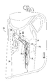
- FIG. 1 shows an example of a vehicle panel assembly configured as a vehicle door that includes a portion of a passenger compartment and a gesture-activated vehicle lighting system according to the disclosed embodiments.
- FIG. 2 is an enlarged view of the vehicle door of FIG.
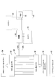
- FIG. 3 is a block diagram illustrating an example of components of a gesture-operated vehicle lighting system according to disclosed embodiments.
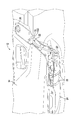
- FIG. 4 is a vehicle door breakout diagram illustrating an example of a gesture-operated vehicle lighting system mounting and wiring structure.
- FIG. 5 is an enlarged breakout view of the vehicle door shown in FIG.
- FIG. 6 shows an example of the operation of one embodiment of the gesture-activated vehicle lighting system.
- FIG. 7 shows an example of the operation of another embodiment of the gesture activated vehicle lighting system.
- FIG. 1 to 5 show a vehicle 10 of an automobile, van, truck, SUV, or other vehicle type, and a vehicle panel assembly 12 configured as a door of the vehicle 10, for example.
- the vehicle panel assembly 12 of this example is configured as a vehicle door on the driver's seat side of the vehicle 10.
- the individual vehicle panel assembly 12 may be used as any or each of the vehicle doors of the vehicle 10, or for example, an interior sidewall panel, a center console, a rear console, a dashboard, an exterior, It can be configured as another vehicle panel of the vehicle 10 such as a vehicle panel or other vehicle trim member.
- the vehicle panel assembly 12 includes a trim assembly 14 that defines a recessed storage area 16.
- the trim assembly 14 is configured as a vehicle door trim assembly 14 that defines a recessed storage area 16 in the vehicle door trim assembly 14.
- the concave storage area 16 can be configured as a storage pocket for a vehicle door.
- the vehicle panel assembly 12 further includes at least one light 18 disposed on the trim assembly 14 and configured to irradiate visible light toward the concave storage area 16, and the concave storage area 16 on the trim assembly 14. And a sensor 20 disposed in close proximity.
- the light 18 can be, for example, a light emitting diode (LED) or other type of light well known in the art.
- the light 18 includes a light emitting surface 18D, and is disposed close to the concave storage region 16 so that the light emitting surface 18D faces the concave storage region 16.
- the sensor 20 of this example may include a proximity sensor, such as an infrared sensor or other type of touchless sensor, configured to detect the presence of an object without touching the sensor 20.
- the sensor 20 may alternatively or additionally be configured to detect the presence of an object in a region proximate to the sensor 20 when the object contacts the sensor 20, eg, a capacitive touch sensor or other type Touch sensors such as touch sensors.
- a region 20 a in FIGS. 1 and 2 is an example of a detection region of a proximity sensor that the sensor 20 can include.
- the light 18 and the sensor 20 are separated from each other and are disposed vertically above the concave storage area 16.
- the sensor 20 is arranged closer to the concave storage area 16 than the light 18.
- the light 18 and the sensor 20 can be arranged at any position suitable for achieving the operation described below. That is, as will be described in detail below, the sensor 20 is configured to activate the light 18 upon detecting the presence of an object that has entered a region close to the sensor 20 including the concave storage region 16. .
- the vehicle door trim assembly 14 includes a door handle portion 22 positioned vertically above the concave storage area 16.
- the light 18 is disposed between the door handle portion 22 and the concave storage area 16.
- the door handle portion 22 includes a lower end 24 and an upper tip 26.
- the light 18 is disposed close to the upper tip 26, and the concave storage area 16 is disposed below the lower end 24.
- the light 18 is disposed close to the lower end 24 of the door handle portion 22, and the concave storage area 16 is disposed below the lower end 24.
- two or more lights 18 can be arranged in both positions or in other positions suitable for illuminating the concave storage area 16.
- the light 18 and the sensor 20 can be electrically connected to, for example, a wire harness 28 disposed in the vehicle door trim assembly 14. As shown, the light 18 and the sensor 20 can be electrically connected to a ground line GND and to an ignition power line IGN that supplies power when the start switch of the vehicle 10 is turned on. Alternatively or additionally, the light 18, sensor 20, or both may be electrically connected to a battery 30 that is independent of the vehicle 10 electrical system.
- the wire harness 28 may be any type of harness having a male connector 32 and a female connector 36, for example.
- the male connector 32 of the wire harness 28 can be fitted with the female connector 34 of a power harness (for example, a power window switch (PWS) harness (not shown)), and the female connector 36 of the wire harness 28 is a vehicle door trim. It can be connected to the male connector 38 of the power window switch 40 of the assembly 14. Therefore, the wire harness 28 can provide power from the power harness to the power window switch 40, and when the dedicated wire harness is not provided to the light 18 and the sensor 20, One skilled in the art will appreciate that the sensor 20 can be connected. 4 and 5 show examples of positions of the light 18, the sensor 20, the wire harness 28, and the power window switch 40 in the vehicle door trim assembly 14. FIG.
- the senor 20 and the light 18 can be configured as a sensor light assembly 42 that includes both the sensor 20 and the light 18 in a common housing.
- control unit 44 can be electrically connected to the light 18 and the sensor 20 and receives electric power from the wire harness 28 through the connection between the ignition power supply line IGN and the ground line GND.
- the control unit 44 preferably includes a microcomputer having a control program for controlling the light 18 and the sensor 20.
- the controller 44 may also include other conventional components such as, for example, input interface circuits, output interface circuits, eg storage devices such as ROM (Read Only Memory) devices, RAM (Random Access Memory) devices, and the like.
- the RAM and ROM store the processing result and a control program executed by the control unit 44.
- the control unit 44 is connected to the light 18 and the sensor 20 and the components of the vehicle 10 so as to be appropriately operable in a conventional manner. It will be apparent to those skilled in the art from this disclosure that the configuration and algorithm of the controller 44 can be any combination of hardware and software that performs the functions of the present invention. As with the light 18 and the sensor 20, the controller 44 can also receive power from the battery 30 or other battery (not shown) as desired. For the purpose of explanation here, the term “sensor” may be used to refer to the combination of the sensor 20 and the controller 44 in terms of a method of controlling the light 18.
- FIG. 6 and 7 show examples of the operation of the light 18 and the sensor 20.
- the light 18 and the sensor 20 are arranged apart from each other.
- the light 18 and the sensor 20 are arranged close to each other, for example, on the sensor light assembly 42.
- the sensor 20 is activated and detected.
- the control unit 44 receives a signal indicating that the object 46 has entered the area from the sensor 20, the control unit 44 can activate the light 18 to irradiate the concave storage area 16.
- the controller 44 can be configured to maintain the operation of the light 18 as long as the sensor 20 continues to detect the presence of the object 46 in the area.
- the controller 44 can be further configured to automatically stop the operation of the light 18 at a predetermined time after the operation of the light. For example, when the sensor 20 no longer detects the presence of the object 46 in the area, the control unit 44 automatically activates the light 18 after a predetermined time has elapsed since the sensor 20 no longer detects the presence of the object 46. Can be stopped. Alternatively or additionally, if the sensor 20 detects the presence of an object 46 that has entered an area proximate to the sensor 20 while the sensor 20 is already operating the light 18, the light 18 is deactivated.
- the control unit 44 can be configured. For example, the controller 44 can activate the light 18 when the sensor 20 indicates that the object 46 is detected, and then activate the light 18 even if the sensor 20 no longer detects the object 46.
- the control unit 44 can stop the operation of the light 18. Therefore, by this operation, the user can operate the light 18 with one gesture, and then can stop the operation of the light 18 with another gesture.
- the control unit 44 may also stop the operation of the light 18 after a predetermined time even if no additional gesture is made, that is, even when the sensor 20 does not detect the object 46 while the light 18 is operating. it can.
- the light 18 can be configured as a type of light that can radiate visible light with different intensities.
- the controller 44 operates the light 18, when the sensor 20 detects the object 46 that enters the area close to the sensor 20, the light 18 is controlled to control the visible light emitted from the light 18.
- the control unit 44 can be further configured to change the intensity. Therefore, the user can change the intensity of the light 18 by performing a plurality of gestures.
- the detection area of the sensor 20 and the irradiation area 18a of the light 18 may be different.
- the detection area 20a of the proximity sensor or the detection area of the touch sensor that can be included in the sensor 20 and the irradiation area 18a of the light 18 do not have to overlap. By doing so, it is possible to prevent the object 46 detected by the sensor 20 from blocking the irradiation of visible light by the light 18.
- the control unit 44 is configured to stop the operation of the light 18 when the sensor 20 detects the object 46, an object in the concave storage region 16 is taken out while the light 18 is operated. It becomes easier.
- the controller 44 can be configured to disable the lights 18 under certain operating conditions of the vehicle 10. For example, if the vehicle door trim assembly 14 is configured as a vehicle door trim assembly on the driver's seat side, the control unit 44 controls the lights 18 until the vehicle 10 travels below a predetermined speed or the vehicle transmission is parked. Can be maintained in a non-operating state. Further, when a sensor (not shown) of the vehicle 10 indicates to the control unit 44 that there is sufficient ambient light in the vehicle interior of the vehicle 10, the control unit 44 can maintain the light 18 in an inoperative state.
- the term “comprising” and its derivatives, as used herein, is an open-ended specification that identifies the existence of a described configuration, element, component, group, integer, and / or process. It is intended to be a term and does not exclude the presence of other structures, elements, components, groups, integers, and / or steps not described. The above also applies to terms having the same meaning as, for example, “including”, “having”, and derivatives thereof. Also, the terms “parts”, “sections”, “parts”, “members”, or “elements” may have the meaning of both a single part or multiple parts even when used in the singular.
- the term “detect” as used herein to describe operations or functions performed by components, sections, devices, etc. includes components, sections, devices, etc. that do not require physical detection. Rather, it includes determination, measurement, modeling, prediction, calculation, etc. to perform an operation or function.
- the term “configured” as used herein to describe a component, section, or portion of a device refers to hardware and / or combination and / or programmed software for performing a desired function. including.
- the terms “substantially”, “about”, and “approximately” with respect to the extent used herein mean that they deviate within a reasonable range from the modified term, and the final result will be significantly different. is not.
- One aspect of the present disclosure includes a trim assembly that defines a recessed storage area, a light provided on the trim assembly and configured to emit visible light toward the recessed storage area, and a recessed storage on the trim assembly.
- a vehicle panel assembly comprising a sensor provided proximate to the region. The sensor is configured to activate a light to irradiate visible light upon detecting the presence of an object that has entered an area close to the sensor, including a concave storage area.
- the light may be arranged close to the concave storage area with its light emitting surface facing the concave storage area.
- the trim assembly may be configured as a vehicle door trim assembly, and the vehicle door trim assembly may define a concave storage area in the vehicle door trim assembly.
- the vehicle door trim assembly may include a door handle portion positioned vertically above the concave storage region, and the light may be disposed between the door handle portion and the concave storage region.
- the door handle portion may include a lower end and an upper tip, the light may be disposed near the upper tip of the door handle portion, and the concave storage area may be disposed below the lower end of the door handle portion. Further, the light may be disposed in the vicinity of the lower end of the door handle portion, and the concave storage area may be disposed separately below the lower end of the door handle portion.
- the light and sensor may be installed vertically above the concave storage area.
- the sensor may be located closer to the concave storage area than the light.
- the sensor and the light may be arranged away from each other.
- At least one of the light and the sensor may be electrically connected to a power window switch of the vehicle door trim assembly. In addition, at least one of the light and the sensor may be electrically connected to a battery that is independent of the electric system of the vehicle.
- the vehicle door trim assembly may be configured as a driver side vehicle door trim assembly.
- the vehicle panel assembly may further include a sensor light assembly including a sensor and a light in a common housing.
- the sensor may include a proximity sensor configured to detect the presence of the object without the object contacting the sensor.
- the proximity sensor may include an infrared sensor.
- the sensor may include a touch sensor configured to detect the presence of an object in a region proximate to the sensor when the object contacts the sensor.
- the sensor may include a capacitive touch sensor.
- the sensor may be further configured to automatically stop the operation of the light at a predetermined time after the operation of the light.
- the senor may be configured to stop the operation of the light when the sensor detects the presence of an object that has entered the area close to the sensor while the sensor is operating the light.
- the light is configured to emit visible light at different intensities, and the sensor turns on the light when the sensor detects the presence of an object that has entered the area proximate to the sensor while the sensor is operating. It may be configured to control and change the intensity with which the light emits visible light.
- the irradiation area where the light emits visible light may be different from the detection area where the sensor detects the presence of an object that has entered the area close to the sensor.
- a vehicle panel assembly including a vehicle lighting system that operates by a gesture.
Landscapes
- Engineering & Computer Science (AREA)
- Mechanical Engineering (AREA)
- Arrangements Of Lighting Devices For Vehicle Interiors, Mounting And Supporting Thereof, Circuits Therefore (AREA)
- Vehicle Interior And Exterior Ornaments, Soundproofing, And Insulation (AREA)
Abstract
車両パネルアッセンブリは、トリムアッセンブリ、ライト、及びセンサーを備える。トリムアッセンブリは、凹状収納領域を規定する。ライトは、トリムアッセンブリ上に配置され、凹状収納領域に向けて可視光線を照射するように構成される。センサーは、トリムアッセンブリ上に凹状収納領域に近接して配置され、凹状収納領域を含む、センサーに近接した領域に入ってきた物体の存在を検出すると、ライトを作動させて可視光線を照射させるように構成されている。
Description
本発明は、ジェスチャーで作動する車両照明システムを含む車両パネルアッセンブリに関する。より具体的には、本発明は、車両トリムパネル内の凹状収納領域に近づく物体の存在を検出すると作動して当該凹状収納領域に向かって可視光線を照射するシステムを含む車両パネルアッセンブリに関する。
今日、殆どの車両は、車室内の様々な領域を照らすための照明装置を含む。例えば、車両は、車室内を全体的に照らすための一つあるいはそれ以上の室内灯、及び特定の領域を照らすための他の照明、例えば、読書灯、バイザーライト、グローブボックスライト、トランク又はハッチライト、ドアライト等を含み得る。これらの照明は、一般に、スイッチを操作することで、又は車両に関連する他の動作、例えば、車両ドアを開ける、グローブボックスを開ける、トランク又はハッチを開ける等の動作を行うことで、選択的に作動させることが可能である。
既知の技術水準に鑑みて、ジェスチャーを行うだけで、車両照明を作動させることが望まれる。例えば、車両ドアパネルのような、車両トリムパネルの凹状収納コンパートメントに関連した照明は、車内にいる人が当該収納コンパートメントにある物を取ろうとした際、又は当該収納コンパートメントに物を入れようとした際、収納コンパートメントが照らされて見やすくなるように、自動的に作動することが望ましい。したがって、本発明の一つの態様は、トリムアッセンブリ、ライト、及びセンサーを備える車両パネルアッセンブリを提供する。トリムアッセンブリは、凹状収納領域を規定する。ライトは、トリムアッセンブリ上に配置され、凹状収納領域に向けて可視光線を照射するように構成されている。センサーは、トリムアッセンブリ上に凹状収納領域に近接して設けられ、凹状収納領域を含む、センサーに近接した領域に入ってきた物体の存在を検出すると、ライトを作動させて可視光線を照射させるように構成されている。
本発明のこれら並びに他の目的、特徴、態様、及び優位性は、添付図面に関連付けて本発明の好適な実施形態を開示する以下の詳細な説明から、当業者に明らかになるであろう。
図面を参照しながら、選択された実施形態を説明する。実施形態の以下の記述は、説明のためにのみ提供されており、請求の範囲により定義される発明及びそれらと均等のものを限定する目的で提供されているのではないことは、本開示から当業者には分かるはずである。
図1から図5は、自動車、バン、トラック、SUV、又はその他の車種の車両10と、例えば、車両10のドアとして構成される車両パネルアッセンブリ12とを示す。詳細には、本例の車両パネルアッセンブリ12は、車両10の運転席側の車両ドアとして構成される。しかしながら、以下の説明から分かるように、個々の車両パネルアッセンブリ12は、車両10の車両ドアの何れか又はその各々として、若しくは、例えば、内装サイドウォールパネル、センターコンソール、リアコンソール、ダッシュボード、外装車両パネル、又はその他の車両トリム部材などの車両10の他の車両パネルとして構成可能である。
更に示されるように、車両パネルアッセンブリ12は、凹状収納領域16を規定するトリムアッセンブリ14を含む。本例では、トリムアッセンブリ14は、車両ドアトリムアッセンブリ14に凹状収納領域16を規定する車両ドアトリムアッセンブリ14として構成される。例えば、凹状収納領域16は、車両ドアの収納ポケットとして構成可能である。車両パネルアッセンブリ12は、更に、トリムアッセンブリ14上に配置され、凹状収納領域16に向かって可視光線を照射するように構成された少なくとも1つのライト18と、トリムアッセンブリ14上に凹状収納領域16に近接して配置されたセンサー20とを含む。
ライト18は、例えば、発光ダイオード(LED)、又は、当該技術分野でよく知られる他の種類のライトであり得る。ライト18は、発光面18Dを含み、発光面18Dが凹状収納領域16に向くように、凹状収納領域16に近接して配置される。本例のセンサー20は、物体がセンサー20に接触することなくその存在を検出するように構成された、例えば、赤外線センサーや他の種類のタッチレスセンサーのような近接センサーを含み得る。センサー20は、代替として又は追加で、センサー20に近接した領域内の物体の存在を、物体がセンサー20と接触すると検出するように構成された、例えば、静電容量式タッチセンサーや他の種類の接触センサーのようなタッチセンサーを含み得る。図1及び図2における領域20aは、センサー20が含み得る近接センサーの検出領域の一例である。
本例では、ライト18及びセンサー20は、互いに離れており、かつ、凹状収納領域16の鉛直上方に配置されている。センサー20は、ライト18よりも凹状収納領域16の近くに配置される。しかしながら、ライト18とセンサー20は、後述する操作を達成するために適した任意の位置に配置可能である。つまり、以下に詳細に説明するように、センサー20は、凹状収納領域16を含む、センサー20に近接した領域に入ってきた物体の存在を検出すると、ライト18を作動させるように構成されている。
車両ドアトリムアッセンブリ14は、凹状収納領域16の鉛直上方に位置するドアハンドル部22を含む。ライト18は、ドアハンドル部22と凹状収納領域16との間に配置される。ドアハンドル部22は、下端24、及び上部先端26を含む。図1、図2、及び図6に示される例では、ライト18は上部先端26に近接して配置され、凹状収納領域16は下端24の下方に離れて配置される。図7に示される例では、替わりに、ライト18はドアハンドル部22の下端24に近接して配置され、凹状収納領域16は下端24の下方に離れて配置される。もちろん、二つ以上のライト18を、両位置、又は、凹状収納領域16を照らすために適した他の位置に配置することも可能である。
図3のブロック図に示されるように、ライト18とセンサー20は、例えば、車両ドアトリムアッセンブリ14内に配置されたワイヤハーネス28に電気的に接続され得る。図示されるように、ライト18とセンサー20は、接地線GNDと、車両10の始動スイッチがオンになると電力を供給するイグニッション電源線IGNとに電気的に接続され得る。代替として又は追加で、ライト18、センサー20、もしくはその両者は、車両10の電気系統から独立したバッテリー30に電気的に接続され得る。
ワイヤハーネス28は、例えば、雄コネクタ32及び雌コネクタ36を有する任意の種類のハーネスでもあり得る。本例では、ワイヤハーネス28の雄コネクタ32は、パワーハーネス(例えば、図示しないパワーウインドウスイッチ(PWS)ハーネス)の雌コネクタ34と嵌合可能であり、ワイヤハーネス28の雌コネクタ36は、車両ドアトリムアッセンブリ14のパワーウインドウスイッチ40の雄コネクタ38に接続可能である。よって、ワイヤハーネス28は、パワーハーネスからパワーウインドウスイッチ40に電力を提供可能であり、ライト18とセンサー20に専用ワイヤハーネスが提供されていない場合は、ワイヤハーネス28により送られる電力にライト18とセンサー20をつなぐことが可能であることは、当業者であれば理解できるであろう。図4及び図5は、車両ドアトリムアッセンブリ14における、ライト18、センサー20、ワイヤハーネス28、及びパワーウインドウスイッチ40の位置の一例を示す。もちろん、これら及び他のコンポーネントを、後述する操作を達成するために適した任意の方法で、車両ドアトリムアッセンブリ14に位置づけることが可能である。更に、センサー20とライト18は、共通のハウジングにセンサー20とライト18を共に備えるセンサーライトアッセンブリ42として構成可能である。
更に、図示されるように、制御部44は、ライト18とセンサー20に電気的に接続可能であり、イグニッション電源線IGNと接地線GNDとの接続を介して、ワイヤハーネス28から電力を受けることが可能である。制御部44は、好ましくは、ライト18とセンサー20を制御する制御プログラムを有するマイクロコンピュータを含む。制御部44はまた、例えば、入力インタフェース回路、出力インタフェース回路、例えば、ROM(読み出し専用メモリ)装置、RAM(ランダムアクセスメモリ)装置のような記憶装置など、他の従来のコンポーネントを含み得る。RAM及びROMは、処理結果と、制御部44により実行される制御プログラムとを記憶する。制御部44は、ライト18及びセンサー20、並びに車両10のコンポーネントに、従来の方法で適宜動作可能に接続される。制御部44の構成及びアルゴリズムが、本発明の機能を実行するハードウェア及びソフトウェアの任意の組合せであり得ることは、本開示から当業者には明らかである。ライト18及びセンサー20と同じように、制御部44も、所望により、バッテリー30又は他のバッテリー(不図示)から電力の供給を受けることが可能である。なお、ここでの説明のため、「センサー」の語は、ライト18を制御する方法という観点から、センサー20と制御部44の組合せに言及するために用いられ得る。
図6及び図7に、ライト18とセンサー20の操作例を示す。図6に示される例では、ライト18とセンサー20は、互いに離れて配置されている。図7に示される例では、ライト18とセンサー20は、互いに近接して配置され、例えば、センサーライトアッセンブリ42上に配置されている。両例に示されるように、例えば、車両10の乗員の手など物体46が、凹状収納領域16を含むセンサー20に近接した領域に入ってくると、センサー20が働いて検出する。制御部44は、センサー20から、物体46が当該領域に入ってきたことを示す信号を受け取ると、ライト18を作動させ、凹状収納領域16を照射させることができる。制御部44は、センサー20が領域内に物体46の存在を検出し続けている限り、ライト18の作動を維持するように構成可能である。
制御部44は、更に、ライトの作動後、所定時間で、自動的にライト18の作動を停止させるように構成可能である。例えば、センサー20が領域内に物体46の存在を検出しなくなった場合、センサー20が物体46の存在を検出しなくなった時から所定時間経過した後に、制御部44が自動的にライト18の作動を停止させることが可能である。代替として又は追加で、センサー20が既にライト18を作動させている間に、センサー20に近接した領域に入ってきた物体46の存在をセンサー20が検出すると、ライト18の作動を停止させるように、制御部44を構成可能である。例えば、制御部44は、物体46が検出されていることをセンサー20から示されると、ライト18を作動させることができ、その後、センサー20が物体46を検出しなくなっても、ライト18を作動状態に維持することができる。しかしながら、ライト18が作動状態である間にセンサー20が物体46を再び検出した場合、制御部44はライト18の作動を停止させることができる。したがって、本操作により、ユーザは、一つのジェスチャーによりライト18を作動させることができ、その後、もう一つのジェスチャーによりライト18の作動を停止させることができる。制御部44は、また、追加のジェスチャーがなされなくとも、つまり、ライト18が作動している間に、センサー20が物体46を検出しない場合でも、所定時間後にライト18の作動を停止させることができる。
更に、ライト18は、異なる強度で可視光線を照射することができる種類のライトとして構成可能である。これにより、制御部44がライト18を作動させている間に、センサー20がセンサー20に近接した領域に入る物体46を検出すると、ライト18を制御して、ライト18から照射される可視光線の強度を変更させるように、制御部44を更に構成可能である。したがって、ユーザは、複数のジェスチャーを行うことで、ライト18の強度を変更することができる。
なお、図6及び図7に示すように、センサー20の検出領域とライト18の照射領域18aとは異なり得る。例えば、センサー20が含み得る近接センサーの検出領域20aやタッチセンサーの検出領域と、ライト18の照射領域18aとは、重なっていなくてもよい。このようにすることで、センサー20が検出した物体46によって、ライト18による可視光線の照射が遮られることを防止できる。また、例えば、センサー20が物体46を検出した際にライト18の作動を停止させるように制御部44を構成した場合に、ライト18を作動させたまま、凹状収納領域16内にある物を取り出すことがより容易になる。
更に、車両10のある種の操作条件下では、ライト18を使用不可とするように、制御部44を構成可能であることは、当業者であれば理解できるであろう。例えば、車両ドアトリムアッセンブリ14が運転席側の車両ドアトリムアッセンブリとして構成されている場合、制御部44は、車両10が所定の速度以下で走行するか、車両の変速機がパーキングになるまで、ライト18を非作動状態に維持可能である。また、車両10のセンサー(不図示)が、車両10の車室内に十分な周辺光があることを制御部44に示す場合、制御部44は、ライト18を非作動状態に維持可能である。
本発明の権利範囲を理解するにあたり、本明細書で使用する用語「備える」及びその派生語は、記載した構成、要素、コンポーネント、グループ、整数、及び/又は工程の存在を特定する開放型の用語であることを意図しており、記載されていない他の構成、要素、コンポーネント、グループ、整数、及び/又は工程の存在を排除するものではない。また、上記は、例えば、「含む」、「有する」、及びその派生語と同様の意味を持つ用語にも当てはまる。また、「部」、「セクション」、「部分」、「部材」、または「要素」の用語は、単数で使用されていても単一の部または複数の部の両方の意味を持ちうる。また、コンポーネント、セクション、装置等により実行される操作又は機能を説明するために本明細書で使用される用語「検出する」は、物理的な検出を必要としないコンポーネント、セクション、装置等を含むが、むしろ、操作又は機能を実行するための、決定、測定、モデル化、予測、又は算出等を含む。デバイスのコンポーネント、セクション、または部の説明のために本明細書で使用される用語「構成される」は、所望の機能を実行するためのハードウェア並びに/又は、組合せ及び/又はプログラムされたソフトウェアを含む。本明細書で使用する程度に関する用語「実質的」、「約」、及び「およそ」は、修飾された用語から妥当な範囲で離れることを意味し、最終的な結果が著しく異なるものとなるものではない。
本発明を例示するために実施形態をいくつか選択したが、別紙の請求項に記載する本発明の権利範囲から逸脱することなく様々な変更及び変形が可能であることは本開示から当業者にとって明らかである。例えば、様々なコンポーネントの大きさ、形、位置または向きは、必要に応じ、及び/又は所望により変更可能である。互いに直接接続または接触するコンポーネントは中間的な構造を間に置くことも可能である。ある一つの要素の機能を二つの要素により実施しても良く、またその反対も可能である。一つの実施形態の構造及び機能は他の実施形態に適用可能である。すべての利点を特定の実施形態において同時に存在させる必要はない。また、単独または他の構成との組合せにより先行技術に類のない各構成は、そのような構成により具現化された構造的及び/又は機能的な概念を含んだ、出願人により更になされた個々の発明を説明するものとして考慮されるべきである。よって、本発明に係る実施形態の上記説明は例示のために提供するに過ぎず、別紙の請求項及びその均等物により定義される発明の限定を目的とするものではない。
本開示の一つの局面は、凹状収納領域を規定するトリムアッセンブリと、トリムアッセンブリ上に設けられ、凹状収納領域に向けて可視光線を照射するように構成されたライトと、トリムアッセンブリ上に凹状収納領域に近接して設けられたセンサーと、を備えた車両パネルアッセンブリである。センサーは、凹状収納領域を含む、センサーに近接した領域に入ってきた物体の存在を検出すると、ライトを作動させて可視光線を照射させるように構成される。
ライトは、その発光面を凹状収納領域に向けて凹状収納領域に近接して配置されてもよい。
トリムアッセンブリは、車両ドアトリムアッセンブリとして構成され、該車両ドアトリムアッセンブリが、凹状収納領域を車両ドアトリムアッセンブリに規定してもよい。
車両ドアトリムアッセンブリは、凹状収納領域の鉛直上方に位置づけられたドアハンドル部を含み、ライトは、ドアハンドル部及び凹状収納領域の間に配置されてもよい。
ドアハンドル部は、下端及び上部先端を含み、ライトは、ドアハンドル部の上部先端に近接して配置され、凹状収納領域は、ドアハンドル部の下端の下方に離れて配置されてもよい。また、ライトは、ドアハンドル部の下端に近接して配置され、凹状収納領域は、ドアハンドル部の下端の下方に離れて配置されてもよい。
ライト及びセンサーは、凹状収納領域の鉛直上方に設置されてもよい。センサーは、ライトよりも凹状収納領域の近くに配置されてもよい。センサー及びライトは、互いに離れて配置されてもよい。
ライト及びセンサーの少なくとも一つは、車両ドアトリムアッセンブリのパワーウインドウスイッチに電気的に接続されてもよい。また、ライト及びセンサーの少なくとも一つは、車両の電気系統から独立したバッテリーに電気的に接続されてもよい。
車両ドアトリムアッセンブリは、運転手側車両ドアトリムアッセンブリとして構成されてもよい。
車両パネルアッセンブリは、共通のハウジングにセンサー及びライトを備えるセンサーライトアッセンブリを更に備えてもよい。
センサーは、物体の存在を、物体がセンサーと接触することなく検出するように構成された近接センサーを含んでもよい。近接センサーは、赤外線センサーを含んでもよい。
センサーは、物体がセンサーと接触すると、センサーに近接した領域の物体の存在を検出するように構成されたタッチセンサーを含んでもよい。センサーは、静電容量式タッチセンサーを含んでもよい。
センサーは更に、ライトを作動させた後、所定の時間で、自動的にライトの作動を停止させるように構成されてもよい。
また、センサーは、センサーがライトを作動させている間に、センサーがセンサーに近接した領域に入ってきた物体の存在を検出すると、ライトの作動を停止させるように構成されてもよい。
ライトは、異なる強度で可視光線を照射するように構成され、センサーは、センサーがライトを作動させている間に、センサーがセンサーに近接した領域に入ってきた物体の存在を検出すると、ライトを制御して、ライトが可視光線を照射する強度を変更させるように構成されてもよい。
ライトが可視光線を照射する照射領域と、センサーがセンサーに近接した領域に入ってきた物体の存在を検出する検出領域とは異なっていてもよい。
本出願は、2015年3月25日に出願された米国特許出願第14/668,548号に基づく優先権を主張しており、該出願の全内容が援用により本明細書に組み込まれる。
本発明によれば、ジェスチャーで作動する車両照明システムを含む車両パネルアッセンブリを提供できる。
12 車両パネルアッセンブリ
14 車両ドアトリムアッセンブリ
16 凹状収納領域
18 ライト
18D 発光面
20 センサー
22 ドアハンドル部
24 下端
26 上部先端
30 バッテリー
40 パワーウインドウスイッチ
42 センサーライトアッセンブリ
46 物体
14 車両ドアトリムアッセンブリ
16 凹状収納領域
18 ライト
18D 発光面
20 センサー
22 ドアハンドル部
24 下端
26 上部先端
30 バッテリー
40 パワーウインドウスイッチ
42 センサーライトアッセンブリ
46 物体
Claims (21)
- 凹状収納領域を規定するトリムアッセンブリと、
前記トリムアッセンブリ上に設けられ、前記凹状収納領域に向けて可視光線を照射するように構成されたライトと、
前記トリムアッセンブリ上に前記凹状収納領域に近接して設けられたセンサーと、
を備え、
前記センサーが、前記凹状収納領域を含む、前記センサーに近接した領域に入ってきた物体の存在を検出すると、前記ライトを作動させて前記可視光線を照射させるように構成されていることを特徴とする車両パネルアッセンブリ。 - 前記ライトは、発光面を含み、
前記ライトは、前記発光面を前記凹状収納領域に向けて前記凹状収納領域に近接して配置されていることを特徴とする請求項1に記載の車両パネルアッセンブリ。 - 前記トリムアッセンブリは、車両ドアトリムアッセンブリとして構成され、
前記車両ドアトリムアッセンブリは、前記凹状収納領域を前記車両ドアトリムアッセンブリに規定することを特徴とする請求項1に記載の車両パネルアッセンブリ。 - 前記車両ドアトリムアッセンブリは、前記凹状収納領域の鉛直上方に位置づけられたドアハンドル部を含み、
前記ライトは、前記ドアハンドル部及び前記凹状収納領域の間に配置されていることを特徴とする請求項3に記載の車両パネルアッセンブリ。 - 前記ドアハンドル部は、下端及び上部先端を含み、
前記ライトは、前記上部先端に近接して配置され、
前記凹状収納領域は、前記下端の下方に離れて配置されていることを特徴とする請求項4に記載の車両パネルアッセンブリ。 - 前記ドアハンドル部は、下端及び上部先端を含み、
前記ライトは、前記下端に近接して配置され、
前記凹状収納領域は、前記下端の下方に離れて配置されていることを特徴とする請求項4に記載の車両パネルアッセンブリ。 - 前記ライト及び前記センサーは、前記凹状収納領域の鉛直上方に設置されていることを特徴とする請求項3に記載の車両パネルアッセンブリ。
- 前記センサーは、前記ライトよりも前記凹状収納領域の近くに配置されていることを特徴とする請求項7に記載の車両パネルアッセンブリ。
- 前記ライト及び前記センサーの少なくとも一つは、前記車両ドアトリムアッセンブリのパワーウインドウスイッチに電気的に接続されていることを特徴とする請求項3に記載の車両パネルアッセンブリ。
- 前記ライト及び前記センサーの少なくとも一つは、前記車両の電気系統から独立したバッテリーに電気的に接続されていることを特徴とする請求項3に記載の車両パネルアッセンブリ。
- 前記車両ドアトリムアッセンブリは、運転手側車両ドアトリムアッセンブリとして構成されていることを特徴とする請求項3に記載の車両パネルアッセンブリ。
- 前記センサー及び前記ライトは、互いに離れて配置されていることを特徴とする請求項1に記載の車両パネルアッセンブリ。
- 共通のハウジングに前記センサー及び前記ライトを備えるセンサーライトアッセンブリを更に備えたことを特徴とする請求項1に記載の車両パネルアッセンブリ。
- 前記センサーは、前記物体の前記存在を、前記物体が前記センサーと接触することなく検出するように構成された近接センサーを含むことを特徴とする請求項1に記載の車両パネルアッセンブリ。
- 前記近接センサーは、赤外線センサーを含むことを特徴とする請求項14に記載の車両パネルアッセンブリ。
- 前記センサーは、前記物体が前記センサーと接触すると、前記センサーに近接した前記領域の前記物体の前記存在を検出するように構成されたタッチセンサーを含むことを特徴とする請求項1に記載の車両パネルアッセンブリ。
- 前記センサーは、静電容量式タッチセンサーを含むことを特徴とする請求項1に記載の車両パネルアッセンブリ。
- 前記センサーは更に、前記ライトを作動させた後、所定の時間で、自動的に前記ライトの作動を停止させるように構成されていることを特徴とする請求項1に記載の車両パネルアッセンブリ。
- 前記センサーは更に、前記センサーが前記ライトを作動させている間に、前記センサーが前記センサーに近接した前記領域に入ってきた物体の前記存在を検出すると、前記ライトの作動を停止させるように構成されていることを特徴とする請求項1に記載の車両パネルアッセンブリ。
- 前記ライトは、異なる強度で前記可視光線を照射するように構成され、
前記センサーは更に、前記センサーが前記ライトを作動させている間に、前記センサーが前記センサーに近接した前記領域に入ってきた物体の前記存在を検出すると、前記ライトを制御して、前記ライトが前記可視光線を照射する強度を変更させるように構成されたことを特徴とする請求項1に記載の車両パネルアッセンブリ。 - 前記ライトが前記可視光線を照射する照射領域と、前記センサーが前記センサーに近接した領域に入ってきた物体の存在を検出する検出領域とが異なることを特徴とする請求項1に記載の車両パネルアッセンブリ。
Applications Claiming Priority (2)
| Application Number | Priority Date | Filing Date | Title |
|---|---|---|---|
| US14/668,548 US9694742B2 (en) | 2015-03-25 | 2015-03-25 | Vehicle panel assembly including a gesture activated vehicle lighting system |
| US14/668,548 | 2015-03-25 |
Publications (1)
| Publication Number | Publication Date |
|---|---|
| WO2016152844A1 true WO2016152844A1 (ja) | 2016-09-29 |
Family
ID=56976245
Family Applications (1)
| Application Number | Title | Priority Date | Filing Date |
|---|---|---|---|
| PCT/JP2016/058956 Ceased WO2016152844A1 (ja) | 2015-03-25 | 2016-03-22 | ジェスチャー作動車両照明システムを含む車両パネルアッセンブリ |
Country Status (2)
| Country | Link |
|---|---|
| US (1) | US9694742B2 (ja) |
| WO (1) | WO2016152844A1 (ja) |
Families Citing this family (20)
| Publication number | Priority date | Publication date | Assignee | Title |
|---|---|---|---|---|
| US10195925B2 (en) * | 2017-02-09 | 2019-02-05 | GM Global Technology Operations LLC | Vehicle door assembly including storage bin that is translatable in fore-aft direction |
| JP1590470S (ja) * | 2017-03-13 | 2018-07-09 | ||
| USD847711S1 (en) * | 2017-03-22 | 2019-05-07 | Ningbo Geely Automobile Research & Development Co., Ltd. | Side skirt for a vehicle |
| ZAA201701740S (en) * | 2017-05-10 | 2019-03-27 | Bayerische Motoren Werke Ag | Motor vehicles |
| USD854978S1 (en) * | 2017-05-24 | 2019-07-30 | Jaguar Land Rover Limited | Combined rear valance and bumper for a vehicle |
| US20180339651A1 (en) * | 2017-05-26 | 2018-11-29 | Ford Global Technologies, Llc | Vehicle lighting system with directional control |
| USD852105S1 (en) * | 2017-06-15 | 2019-06-25 | Jaguar Land Rover Limited | Roof for a vehicle |
| USD899334S1 (en) * | 2017-08-29 | 2020-10-20 | Jaguar Land Rover Limited | Vehicle trunk lid |
| USD940020S1 (en) * | 2017-09-06 | 2022-01-04 | Jaguar Land Rover Limited | Rear spoiler for a vehicle |
| USD839164S1 (en) * | 2017-10-17 | 2019-01-29 | GM Global Technology Operations LLC | Vehicle side door |
| USD898633S1 (en) * | 2018-10-25 | 2020-10-13 | Jaguar Land Rover Limited | Combined front bumper and grille for a vehicle |
| JP1634439S (ja) * | 2018-11-16 | 2019-06-17 | ||
| USD899991S1 (en) * | 2018-12-29 | 2020-10-27 | Guangzhou Automobile Group Co., Ltd. | Automobile door |
| USD928678S1 (en) * | 2019-01-24 | 2021-08-24 | Dv8, Llc | Pair of front doors |
| USD901350S1 (en) * | 2019-09-26 | 2020-11-10 | Ausa Center, S.L.U. | Vehicle body component |
| DE102020100041A1 (de) * | 2020-01-03 | 2021-07-08 | Bayerische Motoren Werke Aktiengesellschaft | Vorrichtung und System zum zeitweisen und antizipierenden Akzentuieren mindestens eines in einem Kraftfahrzeug befindlichen Ablagemittels sowie hiermit ausgestattetes Kraftfahrzeug |
| CN115056745B (zh) * | 2021-12-16 | 2024-05-17 | 博泰车联网科技(上海)股份有限公司 | 车辆、控制车辆的方法以及识别车辆外部手势的方法 |
| DE102022206655A1 (de) | 2022-06-30 | 2024-01-04 | Volkswagen Aktiengesellschaft | Interieurelement für ein Kraftfahrzeug, Verfahren zum Steuern eines Leuchtmittels des Interieurelements sowie Kraftfahrzeug mit einem solchen Interieurelement |
| US12044391B1 (en) * | 2022-07-26 | 2024-07-23 | Apple Inc. | Systems with adjustable lights |
| EP4704924A1 (en) | 2023-04-23 | 2026-03-11 | Translational And Fundamental Technologies Institute Llc | Radionuclide-loaded nanoparticles for focal tissue ablation |
Citations (4)
| Publication number | Priority date | Publication date | Assignee | Title |
|---|---|---|---|---|
| JP2005019155A (ja) * | 2003-06-25 | 2005-01-20 | Ichikoh Ind Ltd | 車両用照明装置 |
| JP2007314073A (ja) * | 2006-05-26 | 2007-12-06 | Toyota Boshoku Corp | 車両用ドアトリム |
| JP2007331648A (ja) * | 2006-06-16 | 2007-12-27 | Piolax Inc | 照明装置 |
| JP2014227018A (ja) * | 2013-05-22 | 2014-12-08 | 本田技研工業株式会社 | 照明装置 |
Family Cites Families (11)
| Publication number | Priority date | Publication date | Assignee | Title |
|---|---|---|---|---|
| US4959637A (en) * | 1989-08-07 | 1990-09-25 | National Safety Devices, Inc. | Emergency signaling device |
| JP3067092B2 (ja) * | 1995-12-08 | 2000-07-17 | 矢崎総業株式会社 | 自動車用ドア |
| DE10360729B4 (de) | 2003-12-23 | 2007-03-01 | Daimlerchrysler Ag | Innenraumleuchte für ein Verkehrsmittel |
| US7185999B2 (en) * | 2005-05-12 | 2007-03-06 | Eric Beare Associates Ltd. | Flashlight with touch sensing on/off operation |
| WO2006130543A2 (en) | 2005-06-02 | 2006-12-07 | Johnson Controls Technology Company | Roof system for a vehicle |
| US8475017B2 (en) * | 2009-02-22 | 2013-07-02 | Ford Global Technologies, Llc | Hidden lamp manufacture process |
| US20100296304A1 (en) * | 2009-05-19 | 2010-11-25 | Marc Hayes | Combination for a vehicle including a self-contained light |
| US8454181B2 (en) | 2010-08-25 | 2013-06-04 | Ford Global Technologies, Llc | Light bar proximity switch |
| US8840288B2 (en) | 2010-11-02 | 2014-09-23 | Nissan North America, Inc. | Vehicle window assembly |
| US9371035B2 (en) * | 2014-03-25 | 2016-06-21 | Ford Global Technologies, Llc | Lighted vehicle bin assembly and method of calibrating same |
| US20160107566A1 (en) * | 2014-10-20 | 2016-04-21 | Nissan North America, Inc. | Vehicle interior lighting structure |
-
2015
- 2015-03-25 US US14/668,548 patent/US9694742B2/en active Active
-
2016
- 2016-03-22 WO PCT/JP2016/058956 patent/WO2016152844A1/ja not_active Ceased
Patent Citations (4)
| Publication number | Priority date | Publication date | Assignee | Title |
|---|---|---|---|---|
| JP2005019155A (ja) * | 2003-06-25 | 2005-01-20 | Ichikoh Ind Ltd | 車両用照明装置 |
| JP2007314073A (ja) * | 2006-05-26 | 2007-12-06 | Toyota Boshoku Corp | 車両用ドアトリム |
| JP2007331648A (ja) * | 2006-06-16 | 2007-12-27 | Piolax Inc | 照明装置 |
| JP2014227018A (ja) * | 2013-05-22 | 2014-12-08 | 本田技研工業株式会社 | 照明装置 |
Also Published As
| Publication number | Publication date |
|---|---|
| US9694742B2 (en) | 2017-07-04 |
| US20160280129A1 (en) | 2016-09-29 |
Similar Documents
| Publication | Publication Date | Title |
|---|---|---|
| US9694742B2 (en) | Vehicle panel assembly including a gesture activated vehicle lighting system | |
| JP6814260B2 (ja) | 自動車用の組立体モジュール | |
| US9982474B2 (en) | Method and system for operating a closure panel of a vehicle | |
| JP6684724B2 (ja) | 光学センサシステムと緊急作動手段とを備える自動車用組立体モジュール | |
| US8975903B2 (en) | Proximity switch having learned sensitivity and method therefor | |
| RU2620713C2 (ru) | Бесконтактный переключатель с управлением чувствительностью и способ управления чувствительностью | |
| CN104812622B (zh) | 包括多个用于机动车侧方或后方周边环境照明的照明器件的机动车 | |
| RU115307U1 (ru) | Бесконтактный датчик с улучшенной активацией | |
| US8994228B2 (en) | Proximity switch having wrong touch feedback | |
| US10160380B1 (en) | Enhanced informational vehicle puddle lamp assemblies | |
| US20150019083A1 (en) | Method and system for hands-free operation of a power window of a vehicle | |
| US8378575B2 (en) | Motor vehicle having a hatchback | |
| JP2017515024A (ja) | 組立体モジュール | |
| US8882174B2 (en) | Operating system and method for a vehicle having an automatically closing hatch | |
| EP3090900B1 (en) | Method and vehicle illumination system for control of vehicle lights | |
| JP2017508986A (ja) | 自動車用の組立体モジュール | |
| US20170167180A1 (en) | Hands-free rear vechicle access system and improvements thereto | |
| US20090066255A1 (en) | Lighting control apparatus for vehicle | |
| US10794107B2 (en) | Vehicle door entry system and method | |
| EP3587186B1 (en) | Vehicle interior lighting system | |
| CN109677358B (zh) | 用于机动车辆的由传感器控制的钥匙系统以及用于对机动车辆进行节能的周围监测的方法 | |
| CN108791041A (zh) | 车辆侧边照明装置 | |
| JP6451390B2 (ja) | 動き検出システム | |
| KR101457071B1 (ko) | 자동차의 트렁크 자동 개폐 장치 | |
| US20240393882A1 (en) | Apparatus for the Contactless Triggering of at Least One Function of a Motor Vehicle |
Legal Events
| Date | Code | Title | Description |
|---|---|---|---|
| 121 | Ep: the epo has been informed by wipo that ep was designated in this application |
Ref document number: 16768747 Country of ref document: EP Kind code of ref document: A1 |
|
| NENP | Non-entry into the national phase |
Ref country code: DE |
|
| 122 | Ep: pct application non-entry in european phase |
Ref document number: 16768747 Country of ref document: EP Kind code of ref document: A1 |
|
| NENP | Non-entry into the national phase |
Ref country code: JP |