WO2016152607A1 - 車両制御装置及び車両の制御方法 - Google Patents
車両制御装置及び車両の制御方法 Download PDFInfo
- Publication number
- WO2016152607A1 WO2016152607A1 PCT/JP2016/057920 JP2016057920W WO2016152607A1 WO 2016152607 A1 WO2016152607 A1 WO 2016152607A1 JP 2016057920 W JP2016057920 W JP 2016057920W WO 2016152607 A1 WO2016152607 A1 WO 2016152607A1
- Authority
- WO
- WIPO (PCT)
- Prior art keywords
- coasting control
- coasting
- clutch
- control end
- vehicle
- Prior art date
- Legal status (The legal status is an assumption and is not a legal conclusion. Google has not performed a legal analysis and makes no representation as to the accuracy of the status listed.)
- Ceased
Links
Images



Classifications
-
- F—MECHANICAL ENGINEERING; LIGHTING; HEATING; WEAPONS; BLASTING
- F16—ENGINEERING ELEMENTS AND UNITS; GENERAL MEASURES FOR PRODUCING AND MAINTAINING EFFECTIVE FUNCTIONING OF MACHINES OR INSTALLATIONS; THERMAL INSULATION IN GENERAL
- F16D—COUPLINGS FOR TRANSMITTING ROTATION; CLUTCHES; BRAKES
- F16D48/00—External control of clutches
- F16D48/02—Control by fluid pressure
-
- F—MECHANICAL ENGINEERING; LIGHTING; HEATING; WEAPONS; BLASTING
- F16—ENGINEERING ELEMENTS AND UNITS; GENERAL MEASURES FOR PRODUCING AND MAINTAINING EFFECTIVE FUNCTIONING OF MACHINES OR INSTALLATIONS; THERMAL INSULATION IN GENERAL
- F16H—GEARING
- F16H61/00—Control functions within control units of change-speed- or reversing-gearings for conveying rotary motion ; Control of exclusively fluid gearing, friction gearing, gearings with endless flexible members or other particular types of gearing
- F16H61/02—Control functions within control units of change-speed- or reversing-gearings for conveying rotary motion ; Control of exclusively fluid gearing, friction gearing, gearings with endless flexible members or other particular types of gearing characterised by the signals used
-
- Y—GENERAL TAGGING OF NEW TECHNOLOGICAL DEVELOPMENTS; GENERAL TAGGING OF CROSS-SECTIONAL TECHNOLOGIES SPANNING OVER SEVERAL SECTIONS OF THE IPC; TECHNICAL SUBJECTS COVERED BY FORMER USPC CROSS-REFERENCE ART COLLECTIONS [XRACs] AND DIGESTS
- Y02—TECHNOLOGIES OR APPLICATIONS FOR MITIGATION OR ADAPTATION AGAINST CLIMATE CHANGE
- Y02T—CLIMATE CHANGE MITIGATION TECHNOLOGIES RELATED TO TRANSPORTATION
- Y02T10/00—Road transport of goods or passengers
- Y02T10/60—Other road transportation technologies with climate change mitigation effect
Definitions
- the present disclosure relates to a vehicle control device and a vehicle control method, and more particularly to coasting control in which power transmission between an engine and driving wheels is interrupted to cause the vehicle to coast.
- the coasting control end condition may be satisfied, and immediately after that, shifting may be performed.
- the coasting control is terminated when the coasting control termination condition is satisfied, and the clutch is brought into the engaged state, so that a state where torque is applied between the clutch and the gear is maintained. For this reason, a shock is generated when the clutch is disengaged again for shifting, or when the gear before shifting is removed.
- the present disclosure provides a vehicle control device that can reduce the occurrence of shock when performing a gear shift.
- the vehicle control device includes a coasting control start execution unit that starts coasting control by setting the clutch disengaged and reducing the engine speed when satisfying a predetermined coasting control start condition.
- Coasting control end execution means for restricting the execution of coasting control end processing for increasing the engine speed and bringing the clutch into a contact state until a predetermined time elapses after starting coasting control.
- the coasting control end execution means does not determine whether a predetermined coasting control end condition, which is a condition for executing coasting control end processing, is satisfied until a predetermined time has elapsed after the start of coasting control. It may be.
- the coasting control end execution means starts coasting control even when it detects that the predetermined coasting control termination condition, which is a condition for executing coasting control termination processing, is satisfied. You may make it wait for execution of the end process of coasting control until predetermined time passes.
- the predetermined time may be equal to or longer than the time until the clutch by the coasting control start execution means is completely disengaged.
- the vehicle control device may further include shift execution means for switching to a predetermined gear stage before the clutch is engaged by the coasting control end execution means.
- the control method starts the coasting control by disengaging the clutch and reducing the engine speed to start the coasting control. Until the predetermined time elapses, the execution of coasting control end processing for increasing the engine speed and bringing the clutch into contact is restricted.
- the vehicle control device of the present disclosure it is possible to reduce the occurrence of shock when performing a shift.
- FIG. 1 is a schematic overall configuration diagram illustrating a vehicle according to an embodiment of the present disclosure.
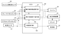
- FIG. 2 is a functional block diagram illustrating an electronic control unit and related configurations according to an embodiment of the present disclosure.
- FIG. 3 is a flowchart of a vehicle control process according to an embodiment of the present disclosure.
- FIG. 4 is a timing chart of control by the vehicle control apparatus according to the conventional example.
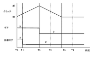
- FIG. 5 is a timing chart of control by the vehicle control device according to an embodiment of the present disclosure.
- FIG. 1 is a schematic overall configuration diagram showing a vehicle 1 according to the present embodiment.
- the output shaft of the engine 10 is connected to the input shaft of the transmission 12 via the clutch 11.
- the output shaft of the transmission 12 is connected to drive wheels (left and right rear wheels) 16L and 16R via a propeller shaft 13, a differential device 14, and a drive shaft 15, respectively.
- the clutch 11 connects and disconnects a power transmission path between the output shaft of the engine 10 and the input shaft of the transmission 12.
- the clutch 11 connects and disconnects the power transmission path according to the hydraulic pressure supplied from the hydraulic control device 18.
- the hydraulic control device 18 generates hydraulic pressure to be supplied to the clutch 11 using the driving force of the engine 10.
- the transmission 12 is, for example, an automatically controlled manual transmission (AMT).
- AMT automatically controlled manual transmission
- the vehicle 1 includes left and right front wheels 17L and 17R, an engine speed sensor 20, a vehicle speed sensor 21, an accelerator pedal sensor 22, a brake pedal sensor 23, and an electronic control unit (hereinafter referred to as an ECU) 50 as an example of a vehicle control device. .
- an ECU electronice control unit
- the engine speed sensor 20 detects a rotation speed Ne of a crankshaft (not shown) of the engine 10.
- the vehicle speed sensor 21 detects the traveling speed VT of the vehicle 1 from the rotational speed of the propeller shaft 13.
- the accelerator pedal sensor 22 detects the accelerator opening Q from the depression amount of the accelerator pedal 31.
- the brake pedal sensor 23 detects the presence or absence of a brake operation by the driver from the amount of depression of the brake pedal 32. The sensor values of these various sensors 20 to 23 are transmitted to the electrically connected ECU 50.
- the ECU 50 performs various controls of the engine 10, the clutch 11, the transmission 12, the hydraulic control device 18, and the like, and includes a known CPU, ROM, RAM, input port, output port, and the like.
- FIG. 2 is a functional block diagram illustrating an electronic control unit and related configurations according to an embodiment of the present disclosure.
- the ECU 50 includes a coasting control start execution unit 51 as an example of coasting control start execution means, a coasting control end execution unit 52 as an example of coasting control end execution means, and a shift execution unit 53 as an example of shift execution means.
- a coasting control start execution unit 51 as an example of coasting control start execution means
- a coasting control end execution unit 52 as an example of coasting control end execution means
- a shift execution unit 53 as an example of shift execution means.
- these functional elements are described as being included in the ECU 50, which is an integral piece of hardware. However, any one of these functional elements may be provided in separate hardware.
- the coasting control start execution unit 51 determines whether or not a predetermined coasting control start condition is satisfied based on the input sensor value.
- the coasting control start condition for example, the accelerator opening may be decreased by a predetermined amount or more.
- the coasting control start condition is not limited to this, and may be various conditions. For example, when the engine 10 having one or more sensor values indicates a driving state in which the driving wheel does not perform positive work on the driving wheel. As a condition.
- the coasting control start execution unit 51 starts coasting control when determining that the coasting control start condition is satisfied. That is, the coasting control start execution unit 51 performs control to reduce the rotational speed of the engine 10 to a predetermined rotational speed (for example, a rotational speed lower than the normal rotational speed of the engine 10 (when the vehicle is stopped)), and Control is performed to cause the hydraulic control device 18 to disengage the clutch 11.
- a predetermined rotational speed for example, a rotational speed lower than the normal rotational speed of the engine 10 (when the vehicle is stopped)
- the coasting control end execution unit 52 determines whether or not a predetermined coasting control end condition is satisfied based on the input sensor value.
- the coasting control end condition for example, the accelerator opening may be increased by a predetermined amount or more.
- the coasting control end condition is not limited to this, and can be various conditions. For example, an operation state in which one or more sensor values do not cause the engine 10 to perform positive work on the drive wheels has been eliminated. This may be a condition.
- the coasting control end execution unit 52 determines that the coasting control end condition is satisfied, the coasting control end process, that is, the rotational speed of the engine 10 is adjusted to, for example, the rotational speed of the input shaft of the transmission 12. And a process of controlling the clutch control unit 52 to bring the clutch 11 into the engaged state.
- the coasting control end execution unit 52 limits the execution of the coasting control end process until a predetermined time (also referred to as the shortest duration) elapses after the coasting control start execution unit 51 starts coasting control.
- the shortest duration may be equal to or longer than the time until the clutch 11 is completely disengaged by the control by the coasting control start execution unit 51.
- the coasting control end execution unit 52 does not perform the determination as to whether or not the coasting control end condition is satisfied until the shortest duration has elapsed since the coasting control start execution unit 51 started the coasting control. By doing so, the execution of coasting control end processing is restricted.
- the coasting control end condition is determined before the coasting control is started before the minimum duration has elapsed, and coasting control end processing is performed after the minimum duration has elapsed. Thus, execution of coasting control end processing may be limited.
- the gear shift execution unit 53 determines a target gear position based on the accelerator opening from the accelerator pedal sensor 22 and the vehicle speed from the vehicle speed sensor 21.
- a method for determining the target shift speed for example, a shift map that prescribes a suitable shift speed corresponding to the accelerator opening and the vehicle speed is stored in the shift execution unit 53 in advance, and the accelerator opening from the accelerator pedal sensor 22 is stored.
- there is a method of identifying an optimum shift stage by referring to a shift map based on the vehicle speed from the vehicle speed sensor 21 and determining the optimum shift stage as a target shift stage.
- the method for determining the target shift speed is not limited to this, and any method can be used.
- a shift speed corresponding to an operation of a shift lever (not shown) by the driver of the vehicle 1 may be set as the target shift speed.
- the shift execution unit 53 performs control to switch the shift stage of the transmission 12 when the current shift stage is different from the determined target shift stage.
- the coasting control end execution unit 52 performs control for bringing the clutch into an engaged state. Before the execution is started, control for switching the gear position is performed. In this way, since the clutch is already in the disengaged state during the shortest duration, it is not necessary to again disengage the clutch for the control to switch the gear position. For this reason, there is no occurrence of a shock that occurs when the clutch is disengaged from the clutch-engaged state and the gear position is released. As a result, the occurrence of shock at the time of shifting can be reduced.
- FIG. 3 is a flowchart of a vehicle control process according to an embodiment of the present disclosure.
- This vehicle control process is started, for example, at the same time as starting the engine 10 (ignition switch key switch ON).
- the coasting control start execution unit 51 determines whether or not the state of the vehicle matches the coasting control start condition (S10). As a result, when the state of the vehicle does not match the coasting control start condition, the coasting control start execution unit 51 repeats the process of step S10 (S10: NO).
- the coasting control start execution unit 51 starts coasting control (S11). Specifically, the coasting control execution unit 51 performs control to reduce the rotational speed of the engine 10 to a predetermined rotational speed (for example, a rotational speed lower than the idle rotational speed of the engine 10), and controls the hydraulic control device 18. Control is performed so that the clutch 11 is disengaged. As a result, fuel consumption in the engine 10 can be appropriately reduced.
- a predetermined rotational speed for example, a rotational speed lower than the idle rotational speed of the engine 10
- the coasting control end execution unit 52 determines whether or not a predetermined time (shortest duration) has elapsed since the coasting control was started (S12). As a result, when the shortest duration has not elapsed (S12: NO), the coasting control end execution unit 52 maintains the coasting control state and repeats the process of step S12.
- the coasting control end execution unit 52 determines whether or not the state of the vehicle matches the coasting control end condition (S13). As a result, when the state of the vehicle does not match the coasting control end condition (S13: NO), the coasting control end execution unit 52 maintains the state of coasting control and repeats the process of step S13.
- the coasting control end execution unit 52 shifts the control to the execution of the shift process by the shift execution unit 53.
- the shift execution unit 53 detects that the current shift stage is different from the determined target shift stage during the shortest duration, the shift execution unit 53 performs control to switch the shift stage, and then performs control.
- the process returns to the coasting control end execution unit 52 (S14).
- the clutch 11 is completely disengaged, so that almost no shock is generated when the gear position is changed. If the current shift speed is not different from the determined target shift speed, the shift execution section 53 immediately returns control to the coasting control end execution section 52.
- the coasting control end execution unit 52 performs coasting control end processing when the control is returned from the shift execution unit 53 (S15).
- the coasting control end execution unit 52 starts control to increase the rotational speed of the engine 10 so as to match the rotational speed of the input shaft of the transmission 12, for example, and causes the hydraulic control device 18 to 11 is controlled to be in a contact state.
- the clutch 11 is brought into the engaged state in a state where the transmission 12 is at the target shift stage.
- FIG. 4 is a timing chart of control by the vehicle control device according to the conventional example.
- FIG. 5 is a timing chart of control by the vehicle control device according to an embodiment of the present disclosure.
- the coasting control is immediately terminated. That is, the process for bringing the clutch 11 into the engaged state is started.
- the control to bring the clutch 11 into the engaged state is started from the time when the change of the gear position is completed (time T3), and at the time T4, the clutch is completely in the engaged state, and the shift is completed.
- a shock is generated at the time of shifting immediately after the coasting control is finished.
- the process of ending coasting control (the process of bringing the clutch into an engaged state) until the time T5 when the shortest duration has elapsed from the time T0 when the coasting control was started.
- the process of increasing the engine speed is limited.
- the clutch 11 is completely disengaged.
- the shift execution unit 53 performs the shift before the clutch 11 is brought into the engaged state by the coasting control end processing. Stage switching is performed. At this time, the clutch 11 is completely disengaged, so that even when the gear shift execution unit 53 switches the gear position, the shock hardly occurs.
- the process of bringing the clutch 11 into the engaged state is started from the time (time T5) when the shift stage is switched by the shift execution unit 53.
- the clutch is completely engaged at time T6 earlier than time T4 at which the shift is completed in the conventional example, and the shift is completed.
- the coasting control is continued until the minimum duration time has elapsed since the coasting control was started. There is no need to disengage the clutch again, and the occurrence of shocks related to shifting can be reduced. Further, the shift can be completed earlier than in the past.
- the AMT has been described as an example.
- the transmission may be another type of automatic transmission (for example, a torque controller) as long as the clutch can be automatically connected and disconnected.
- Type transmission for example, a torque controller
- the vehicle control device of the present disclosure can be used to reduce the occurrence of a shock when performing a shift.
- Vehicle 10 Engine 11 Clutch 12 Transmission 13 Propeller Shaft 14 Differential Device 15 Drive Shaft 50 ECU 51 coasting control start execution unit 52 coasting control end execution unit 53 shift execution unit
Landscapes
- Engineering & Computer Science (AREA)
- General Engineering & Computer Science (AREA)
- Mechanical Engineering (AREA)
- Physics & Mathematics (AREA)
- Fluid Mechanics (AREA)
- Hydraulic Clutches, Magnetic Clutches, Fluid Clutches, And Fluid Joints (AREA)
- Control Of Transmission Device (AREA)
Abstract
車両制御装置は、所定の惰行制御開始条件を充足する際に、クラッチ(11)を断状態にするとともにエンジン回転数を低下させて惰行制御を開始する惰行制御開始実行部(51)と、惰行制御を開始してから所定時間が経過するまで、エンジン回転数を上昇させるとともにクラッチ(11)を接状態にさせる惰行制御の終了処理の実行を制限する惰行制御終了実行部(52)と、を有する。
Description
本開示は、車両制御装置及び車両の制御方法に関し、特に、エンジンと駆動輪との間の動力伝達を遮断して車両を惰行走行させる惰行制御に関する。
車両の走行時に、クラッチを断状態にして、もしくは、変速機をニュートラルにすることによりエンジンと駆動輪との間の動力伝達を遮断し、その間、エンジンの回転数を低下させることにより、燃料の消費を低減する惰行制御が知られている。
このような惰行制御を行う車両において、変速を行う場合における種々の技術が開示されている(例えば、特許文献1、特許文献2参照)。
例えば、惰行制御を行う車両においては、所定の惰行制御の終了条件を満たした場合には、エンジン回転数を上昇させて、クラッチを接状態にさせて惰行制御を終了する。また、惰行制御を終了した後に、人為的又は自動的に変速する可能性がある。この場合には、再度クラッチを断状態にさせて、ギアを変えて、クラッチを接状態にさせることとなる。
例えば、惰行制御を開始した直後に、惰行制御の終了条件を満たし、その直後に、変速が行われることがあり得る。この場合には、惰行制御の終了条件を満たしたことにより惰行制御が終了されて、クラッチが接状態にされるのでクラッチとギアとの間にトルクがかかった状態が維持される。このため、変速を行うために再びクラッチを断状態にする際や、変速前のギアを抜く際にショックが発生する。
本開示は、変速を行う際のショックの発生を低減することのできる車両制御装置を提供する。
本開示の一観点に係る車両制御装置は、所定の惰行制御開始条件を充足する際に、クラッチを断状態にするとともにエンジン回転数を低下させて惰行制御を開始する惰行制御開始実行手段と、惰行制御を開始してから所定時間が経過するまで、エンジン回転数を上昇させるとともにクラッチを接状態にさせる惰行制御の終了処理の実行を制限する惰行制御終了実行手段と、を有する。
上記車両制御装置において、惰行制御終了実行手段は、惰行制御を開始してから所定時間が経過するまで、惰行制御の終了処理を実行する条件である所定の惰行制御終了条件の充足を判定しないようにしてもよい。
上記車両制御装置において、惰行制御終了実行手段は、惰行制御の終了処理を実行する条件である所定の惰行制御終了条件を充足することを検知した場合であっても、惰行制御を開始してから所定時間が経過するまで、惰行制御の終了処理の実行を待機するようにしてもよい。
上記車両制御装置において、所定時間は、惰行制御開始実行手段によるクラッチが完全に断状態になるまでの時間以上であってもよい。
上記車両制御装置において、惰行制御終了実行手段によってクラッチが接状態になるまでに、所定の変速段に切り替える変速実行手段をさらに有するようにしてもよい。
本開示の一観点に係る制御方法は、所定の惰行制御開始条件を充足する際に、クラッチを断状態にするとともにエンジン回転数を低下させて惰行制御を開始し、前記惰行制御を開始してから所定時間が経過するまで、エンジン回転数を上昇させるとともに前記クラッチを接状態にさせる惰行制御の終了処理の実行を制限する。
本開示の車両制御装置によれば、変速を行う際のショックの発生を低減することができる。
以下、添付図面に基づいて、本開示の一実施形態に係る車両制御装置を説明する。同一の部品には同一の符号を付してあり、それらの名称および機能も同じである。したがって、それらについての詳細な説明は繰返さない。
図1は、本実施形態に係る車両1を示す模式的な全体構成図である。エンジン10の出力軸は、クラッチ11を介して変速機12の入力軸に接続されている。変速機12の出力軸は、プロペラシャフト13、差動装置14、ドライブシャフト15を介して駆動輪(左右後輪)16L,16Rにそれぞれ接続されている。
クラッチ11は、エンジン10の出力軸と、変速機12の入力軸との間の動力伝達経路を断接する。本実施形態では、クラッチ11は、油圧制御装置18から供給される油圧に応じて動力伝達経路を断接する。油圧制御装置18は、エンジン10の駆動力を利用してクラッチ11に供給する油圧を生成する。
変速機12は、例えば、自動制御式マニュアルトランスミッション(AMT)である。
車両1は、左右前輪17L,17R、エンジン回転数センサ20、車速センサ21、アクセルペダルセンサ22、ブレーキペダルセンサ23、車両制御装置の一例としての電子制御ユニット(以下、ECUと称する)50を備える。
エンジン回転数センサ20は、エンジン10の図示しないクランクシャフトの回転数Neを検出する。車速センサ21は、プロペラシャフト13の回転速度から車両1の走行速度VTを検出する。アクセルペダルセンサ22は、アクセルペダル31の踏み込み量からアクセル開度Qを検出する。ブレーキペダルセンサ23は、ブレーキペダル32の踏み込み量から運転者によるブレーキ操作の有無を検出する。これら各種センサ類20~23のセンサ値は、電気的に接続されたECU50に送信される。
ECU50は、エンジン10、クラッチ11、変速機12、油圧制御装置18等の各種制御を行うもので、公知のCPUやROM、RAM、入力ポート、出力ポート等を備える。
図2は、本開示の一実施形態に係る電子制御ユニット及び関連する構成を示す機能ブロック図である。
ECU50は、惰行制御開始実行手段の一例としての惰行制御開始実行部51と、惰行制御終了実行手段の一例としての惰行制御終了実行部52と、変速実行手段の一例としての変速実行部53とを一部の機能要素として有する。これら各機能要素は、本実施形態では一体のハードウェアであるECU50に含まれるものとして説明するが、これらのいずれか一部を別体のハードウェアに設けることもできる。
惰行制御開始実行部51は、入力されるセンサ値に基づいて、所定の惰行制御開始条件を満たすか否かを判定する。惰行制御開始条件としては、例えば、アクセル開度が所定量以上低下した場合としてもよい。なお、惰行制御開始条件としては、これに限られず、種々の条件とすることができ、例えば、1以上のセンサ値がのエンジン10が駆動輪に対して正の仕事をしない運転状態を示す場合を条件としてもよい。
惰行制御開始実行部51は、惰行制御開始条件を満たすと判定した場合には、惰行制御を開始する。すなわち、惰行制御開始実行部51は、エンジン10の回転数を所定の回転数(例えば、エンジン10の通常(車両停止時)のアイドル回転数よりも低い回転数)に低下させる制御を行うとともに、油圧制御装置18にクラッチ11を断状態にさせるように制御する。
惰行制御終了実行部52は、入力されるセンサ値に基づいて、所定の惰行制御終了条件を満たすか否かを判定する。惰行制御終了条件としては、例えば、アクセル開度が所定量以上増加した場合としてもよい。なお、惰行制御終了条件としては、これに限られず、種々の条件とすることができ、例えば、1以上のセンサ値がエンジン10が駆動輪に対して正の仕事をしない運転状態が解消されたことを示す場合を条件としてもよい。
惰行制御終了実行部52は、惰行制御終了条件を満たすと判定した場合には、惰行制御の終了処理、すなわち、エンジン10の回転数を、例えば、変速機12のインプットシャフトの回転数に合わせるように上昇させる制御を行うとともに、クラッチ制御部52にクラッチ11を接状態にさせるように制御する処理を実行する。
惰行制御終了実行部52は、惰行制御開始実行部51により惰行制御が開始されてから所定時間(最短継続時間ともいう。)が経過するまで、上述の惰行制御の終了処理の実行を制限する。ここで、最短継続時間は、惰行制御開始実行部51による制御により、クラッチ11が完全に断状態となるまでの時間以上としてもよい。本実施形態では、惰行制御終了実行部52は、惰行制御開始実行部51により惰行制御が開始されてから最短継続時間が経過するまで、惰行制御終了条件を満たすか否かの判定を実行しないようにすることにより、惰行制御の終了処理の実行を制限している。なお、惰行制御が開始されてから最短継続時間が経過する前に惰行制御終了条件を満たすか否かの判定を実行しておき、最短継続時間が経過した後に惰行制御の終了処理を行うようにして、惰行制御の終了処理の実行を制限するようにしてもよい。
変速実行部53は、アクセルペダルセンサ22からのアクセル開度と、車速センサ21からの車速とに基づいて、目標変速段を決定する。目標変速段を決定する方法としては、例えば、アクセル開度及び車速に対応する好適な変速段を規定する変速マップを予め変速実行部53に記憶させておき、アクセルペダルセンサ22からのアクセル開度及び車速センサ21からの車速とに基づいて変速マップを参照することにより、最適な変速段を特定し、この最適な変速段を目標変速段として決定する方法がある。なお、目標変速段を決定する方法としては、これに限られず任意の方法を用いることができる。また、車両1の運転者による図示しないシフトレバーの操作に対応する変速段を目標変速段としてもよい。
変速実行部53は、現在の変速段が、決定した目標変速段と異なる場合に、変速機12の変速段を切り替える制御を行う。なお、本実施形態では、最短継続時間中において、現在の変速段が、決定した目標変速段と異なることを検出した場合には、惰行制御終了実行部52により、クラッチを接状態にする制御の実行が開始される前に、変速段を切り替える制御を行う。このようにすると、最短継続期間中にすでにクラッチが断状態となっているので、変速段を切り替える制御のために、改めてクラッチを断状態とする必要がない。このため、クラッチ接の状態からクラッチを断状態にするとともに変速段を抜く際に発生してしまうショックが発生することがない。これにより、変速時のショックの発生を低減することができる。
次に、本開示の一実施形態に係る車両制御処理について説明する。
図3は、本開示の一実施形態に係る車両制御処理のフローチャートである。
この車両制御処理は、例えば、エンジン10の始動(イグニッションスイッチのキースイッチON)と同時に開始される。
惰行制御開始実行部51は、車両の状態が惰行制御開始条件に合致するか否かを判定する(S10)。この結果、車両の状態が惰行制御開始条件に合致しない場合には、惰行制御開始実行部51は、ステップS10の処理を繰り返す(S10:NO)。
一方、車両の状態が惰行制御開始条件に合致する場合(S10:YES)には、惰行制御開始実行部51は、惰行制御を開始する(S11)。具体的には、惰行制御実行部51は、エンジン10の回転数を所定の回転数(例えば、エンジン10のアイドル回転数よりも低い回転数)に低下させる制御を行うとともに、油圧制御装置18にクラッチ11を断状態にさせるように制御する。この結果、エンジン10における燃料消費を適切に低減することができる。
次いで、惰行制御終了実行部52は、惰行制御が開始されてから所定時間(最短継続時間)経過しているか否かを判定する(S12)。この結果、最短継続時間を経過していない場合(S12:NO)には、惰行制御終了実行部52は、惰行制御の状態を維持し、ステップS12の処理を繰り返す。
一方、最短継続時間を経過している場合(S12:YES)には、惰行制御終了実行部52は、車両の状態が惰行制御終了条件に合致するか否かを判定する(S13)。この結果、車両の状態が惰行制御終了条件に合致しない場合(S13:NO)には、惰行制御終了実行部52は、惰行制御の状態を維持し、ステップS13の処理を繰り返す。
一方、車両の状態が惰行制御終了条件に合致する場合(S13:YES)には、惰行制御終了実行部52は、変速実行部53による変速処理の実行に制御を移す。この場合、変速実行部53は、最短継続時間中に、現在の変速段が、決定した目標変速段と異なることを検出している場合には、変速段を切り替える制御を行い、その後、制御を惰行制御終了実行部52に戻す(S14)。この時点においては、クラッチ11は完全に断状態となっているので、変速段の切り替え時には、ショックがほとんど発生しない。なお、現在の変速段が、決定した目標変速段と異ならない場合には、変速実行部53は、すぐに制御を惰行制御終了実行部52に戻す。
惰行制御終了実行部52は、変速実行部53から制御を戻されると、惰行制御終了処理を行う(S15)。惰行制御終了処理においては、惰行制御終了実行部52は、エンジン10の回転数を、例えば変速機12のインプットシャフトの回転数に合わせるように上昇させる制御を開始するとともに、油圧制御装置18にクラッチ11を接状態にさせるように制御する。これにより、変速機12が目標変速段となった状態で、クラッチ11が接状態となる。
次に、本開示の一実施形態に係る車両制御装置による作用効果について説明する。
図4は従来例に係る車両制御装置による制御のタイミングチャートである。図5は、本開示の一実施形態に係る車両制御装置による制御のタイミングチャートである。
従来例に係る車両制御装置においては、時刻T0に惰行制御が開始されると、クラッチ11を断状態にするように制御が開始される。ここで、惰行制御が開始された直後の時刻T1において、車両の状態が惰行制御終了条件に合致するようになったものとし、また、変速実行部53は、目標変速段(目標ギア)を3速から2速に変えたものとする。
時刻T1においては、クラッチ11は、完全には断状態になっていない。
この場合には、直ちに惰行制御を終了する処理が行われる。すなわち、クラッチ11を接状態にする処理が開始される。
時刻T2において、クラッチ11が完全に接状態となり、目標変速段が変わっており変速をする必要があるので、その時点からクラッチ11を断状態にする制御が開始され、時刻T3において、クラッチ11が完全に断状態となる。時刻T2においては、クラッチ11には、エンジン10と駆動輪とを接続することによるトルクが発生しており、クラッチ11を断状態にする際には、このトルクの影響により、ショックが発生する。また、クラッチ11が完全に断状態となっていない時点(時刻T3より前)に、変速段の切り替えを開始するようにすると、変速段を抜く場合にショックが発生する。
変速段の切り替えが終了した時点(時刻T3)からクラッチ11を接状態にする制御が開始されて、時刻T4において、クラッチが完全に接状態となり、変速が完了する。
このように、従来例に係る車両制御装置においては、惰行制御を終了した直後における変速時に、ショックが発生する。
一方、本実施形態に係る車両制御装置においては、時刻T0に惰行制御が開始されると、クラッチ11を断状態にする制御が開始される。ここで、惰行制御が開始された直後の時刻T1において、車両の状態が惰行制御終了条件に合致するようになったものとし、また、変速実行部53は、目標変速段(目標ギア)を3速から2速に変えたものとする。
本実施形態に係る車両制御装置においては、惰行制御が開始された時刻T0から最短継続時間が経過した時刻T5になるまでの間は、惰行制御を終了する処理(クラッチを接状態にする処理と、エンジン回転数を上昇させる処理)が制限される。時刻T5においては、クラッチ11は、完全に断状態となる。
そして、最短継続時間が経過した時刻T5において、車両の状態が惰行制御終了条件に合致すると判定されると、惰行制御の終了処理によりクラッチ11を接状態にする前に、変速実行部53による変速段の切り替えが実行される。この時点においては、クラッチ11は完全に断状態となっているので、変速実行部53による変速段の切り替えが行われてもショックはほとんど発生しない。
そして、変速実行部53による変速段の切り替えが行われた時点(時刻T5)からクラッチ11を接状態にする処理が開始される。この結果、本実施形態では、従来例で変速が完了した時刻T4よりも早い時刻T6において、クラッチが完全に接状態となり、変速が完了する。
このように、本実施形態に係る車両制御装置によると、惰行制御が開始されてから最短継続時間が経過するまで惰行制御を継続するようにしているので、惰行制御の終了時に変速を行う場合において改めてクラッチを断状態とする必要がなく、変速に係るショックの発生を低減することができる。また、従来よりも早期に変速を完了することができる。
なお、本開示は、上述の実施形態に限定されるものではなく、本開示の趣旨を逸脱しない範囲で、適宜変形して実施することが可能である。
例えば、上記実施形態では、AMTを例に説明していたが、本開示はこれに限られず、自動でクラッチを断接することができれば、トランスミッションは、他の方式の自動式トランスミッション(例えば、トルクコントローラ式トランスミッション)であってもよい。
本出願は、2015年03月26日付で出願された日本国特許出願(特願2015-063952)に基づくものであり、その内容はここに参照として取り込まれる。
本開示の車両制御装置は、変速を行う際のショックの発生を低減することに利用できる。
1 車両
10 エンジン
11 クラッチ
12 変速機
13 プロペラシャフト
14 差動装置
15 ドライブシャフト
50 ECU
51 惰行制御開始実行部
52 惰行制御終了実行部
53 変速実行部
10 エンジン
11 クラッチ
12 変速機
13 プロペラシャフト
14 差動装置
15 ドライブシャフト
50 ECU
51 惰行制御開始実行部
52 惰行制御終了実行部
53 変速実行部
Claims (6)
- 所定の惰行制御開始条件を充足する際に、クラッチを断状態にするとともにエンジン回転数を低下させて惰行制御を開始する惰行制御開始実行手段と、
前記惰行制御を開始してから所定時間が経過するまで、エンジン回転数を上昇させるとともに前記クラッチを接状態にさせる惰行制御の終了処理の実行を制限する惰行制御終了実行手段と、を有する
車両制御装置。 - 前記惰行制御終了実行手段は、前記惰行制御を開始してから所定時間が経過するまで、前記惰行制御の終了処理を実行する条件である所定の惰行制御終了条件の充足を判定しない
請求項1に記載の車両制御装置。 - 前記惰行制御終了実行手段は、前記惰行制御の終了処理を実行する条件である所定の惰行制御終了条件を充足することを検知した場合であっても、前記惰行制御を開始してから所定時間が経過するまで、前記惰行制御の終了処理の実行を待機する請求項1に記載の車両制御装置。
- 前記所定時間は、前記惰行制御開始実行手段によるクラッチが完全に断状態となるまでの時間以上である請求項1から3の何れか一項に記載の車両制御装置。
- 前記惰行制御終了実行手段によって前記クラッチの接状態となるまでに、所定の変速段に切り替える変速実行手段をさらに有する請求項1から4の何れか一項に記載の車両制御装置。
- 所定の惰行制御開始条件を充足する際に、クラッチを断状態にするとともにエンジン回転数を低下させて惰行制御を開始し、
前記惰行制御を開始してから所定時間が経過するまで、エンジン回転数を上昇させるとともに前記クラッチを接状態にさせる惰行制御の終了処理の実行を制限する、
車両の制御方法。
Applications Claiming Priority (2)
| Application Number | Priority Date | Filing Date | Title |
|---|---|---|---|
| JP2015063952A JP2016183715A (ja) | 2015-03-26 | 2015-03-26 | 車両制御装置 |
| JP2015-063952 | 2015-03-26 |
Publications (1)
| Publication Number | Publication Date |
|---|---|
| WO2016152607A1 true WO2016152607A1 (ja) | 2016-09-29 |
Family
ID=56977542
Family Applications (1)
| Application Number | Title | Priority Date | Filing Date |
|---|---|---|---|
| PCT/JP2016/057920 Ceased WO2016152607A1 (ja) | 2015-03-26 | 2016-03-14 | 車両制御装置及び車両の制御方法 |
Country Status (2)
| Country | Link |
|---|---|
| JP (1) | JP2016183715A (ja) |
| WO (1) | WO2016152607A1 (ja) |
Citations (3)
| Publication number | Priority date | Publication date | Assignee | Title |
|---|---|---|---|---|
| JP2006342832A (ja) * | 2005-06-07 | 2006-12-21 | Isuzu Motors Ltd | 走行体の制御装置及び制御方法 |
| JP2008106829A (ja) * | 2006-10-24 | 2008-05-08 | Toyota Motor Corp | 車両用自動変速機の変速制御装置 |
| JP2012031942A (ja) * | 2010-07-30 | 2012-02-16 | Isuzu Motors Ltd | 惰行制御装置 |
-
2015
- 2015-03-26 JP JP2015063952A patent/JP2016183715A/ja active Pending
-
2016
- 2016-03-14 WO PCT/JP2016/057920 patent/WO2016152607A1/ja not_active Ceased
Patent Citations (3)
| Publication number | Priority date | Publication date | Assignee | Title |
|---|---|---|---|---|
| JP2006342832A (ja) * | 2005-06-07 | 2006-12-21 | Isuzu Motors Ltd | 走行体の制御装置及び制御方法 |
| JP2008106829A (ja) * | 2006-10-24 | 2008-05-08 | Toyota Motor Corp | 車両用自動変速機の変速制御装置 |
| JP2012031942A (ja) * | 2010-07-30 | 2012-02-16 | Isuzu Motors Ltd | 惰行制御装置 |
Also Published As
| Publication number | Publication date |
|---|---|
| JP2016183715A (ja) | 2016-10-20 |
Similar Documents
| Publication | Publication Date | Title |
|---|---|---|
| JP5648698B2 (ja) | ハイブリッド車両の制御装置 | |
| JP6336805B2 (ja) | ハイブリッド車両の変速制御方法 | |
| KR101651032B1 (ko) | 프리휠링 엔진 정지 기능을 가진 차량의 구동 트레인을 작동하기 위한 방법, 제어장치 및 차량 | |
| EP2949528B1 (en) | Hybrid vehicle control device | |
| CN103608228B (zh) | 用于使车辆加速的方法以及混合动力车辆 | |
| JP2016101874A (ja) | 四輪駆動車の制御装置 | |
| WO2015132643A1 (en) | Start-stop control in a vehicle with mechanical gear shift lever for quickly starting the engine after an automatic stop | |
| JP6408881B2 (ja) | 駆動力制御装置 | |
| JP2005030400A (ja) | 内燃機関の始動=停止=作動の制御のための方法及び制御装置 | |
| JP2014201220A (ja) | ハイブリッド車の駆動制御装置 | |
| WO2013179753A1 (ja) | エンジン制御装置 | |
| WO2016152613A1 (ja) | 車両制御装置及び車両の制御方法 | |
| JP7206600B2 (ja) | 走行制御装置および車両 | |
| WO2016152604A1 (ja) | 車両制御装置及び車両の制御方法 | |
| JP2016183715A (ja) | 車両制御装置 | |
| JP2018141425A (ja) | 駆動力制御装置 | |
| JP5355164B2 (ja) | 自動変速機の制御装置 | |
| JP2017067205A (ja) | 車両用制御装置 | |
| JP6036328B2 (ja) | ハイブリッド車両の制御装置 | |
| JP2015194111A (ja) | アイドルストップ制御装置 | |
| JP6187402B2 (ja) | 車両駆動ユニットの制御装置 | |
| JP6089951B2 (ja) | ハイブリッド車の駆動制御装置 | |
| EP3483482B1 (en) | Driving-force control device | |
| JP2019094820A (ja) | 車両の制御装置 | |
| JP2018141424A (ja) | 駆動力制御装置 |
Legal Events
| Date | Code | Title | Description |
|---|---|---|---|
| 121 | Ep: the epo has been informed by wipo that ep was designated in this application |
Ref document number: 16768510 Country of ref document: EP Kind code of ref document: A1 |
|
| NENP | Non-entry into the national phase |
Ref country code: DE |
|
| 122 | Ep: pct application non-entry in european phase |
Ref document number: 16768510 Country of ref document: EP Kind code of ref document: A1 |