WO2016152578A1 - Inductor and protection circuit - Google Patents
Inductor and protection circuit Download PDFInfo
- Publication number
- WO2016152578A1 WO2016152578A1 PCT/JP2016/057746 JP2016057746W WO2016152578A1 WO 2016152578 A1 WO2016152578 A1 WO 2016152578A1 JP 2016057746 W JP2016057746 W JP 2016057746W WO 2016152578 A1 WO2016152578 A1 WO 2016152578A1
- Authority
- WO
- WIPO (PCT)
- Prior art keywords
- coil
- inductor
- short
- current
- circuit
- Prior art date
Links
- XEEYBQQBJWHFJM-UHFFFAOYSA-N Iron Chemical compound [Fe] XEEYBQQBJWHFJM-UHFFFAOYSA-N 0.000 claims abstract description 38
- 238000004804 winding Methods 0.000 claims abstract description 25
- 229910052742 iron Inorganic materials 0.000 claims abstract description 16
- 230000007423 decrease Effects 0.000 claims abstract description 13
- 230000008878 coupling Effects 0.000 claims description 14
- 238000010168 coupling process Methods 0.000 claims description 14
- 238000005859 coupling reaction Methods 0.000 claims description 14
- 230000000670 limiting effect Effects 0.000 claims description 9
- 239000000696 magnetic material Substances 0.000 claims description 7
- 230000009471 action Effects 0.000 claims description 3
- 230000000694 effects Effects 0.000 abstract description 4
- 239000003822 epoxy resin Substances 0.000 description 35
- 229920000647 polyepoxide Polymers 0.000 description 35
- 229920005989 resin Polymers 0.000 description 20
- 239000011347 resin Substances 0.000 description 20
- 238000001723 curing Methods 0.000 description 16
- 239000000843 powder Substances 0.000 description 10
- 238000001746 injection moulding Methods 0.000 description 9
- 239000000463 material Substances 0.000 description 9
- 239000004734 Polyphenylene sulfide Substances 0.000 description 8
- 239000003795 chemical substances by application Substances 0.000 description 8
- 239000006247 magnetic powder Substances 0.000 description 8
- 229920000069 polyphenylene sulfide Polymers 0.000 description 8
- WABPQHHGFIMREM-UHFFFAOYSA-N lead(0) Chemical compound [Pb] WABPQHHGFIMREM-UHFFFAOYSA-N 0.000 description 7
- 238000000034 method Methods 0.000 description 7
- 229920005992 thermoplastic resin Polymers 0.000 description 7
- 239000011248 coating agent Substances 0.000 description 6
- 238000000576 coating method Methods 0.000 description 6
- 230000035699 permeability Effects 0.000 description 6
- 230000008859 change Effects 0.000 description 5
- 230000000052 comparative effect Effects 0.000 description 5
- -1 polyethylene Polymers 0.000 description 5
- 239000002994 raw material Substances 0.000 description 5
- 229920001187 thermosetting polymer Polymers 0.000 description 5
- RYGMFSIKBFXOCR-UHFFFAOYSA-N Copper Chemical compound [Cu] RYGMFSIKBFXOCR-UHFFFAOYSA-N 0.000 description 4
- 239000004593 Epoxy Substances 0.000 description 4
- 239000004020 conductor Substances 0.000 description 4
- 230000004907 flux Effects 0.000 description 4
- 239000011230 binding agent Substances 0.000 description 3
- IISBACLAFKSPIT-UHFFFAOYSA-N bisphenol A Chemical compound C=1C=C(O)C=CC=1C(C)(C)C1=CC=C(O)C=C1 IISBACLAFKSPIT-UHFFFAOYSA-N 0.000 description 3
- PXKLMJQFEQBVLD-UHFFFAOYSA-N bisphenol F Chemical compound C1=CC(O)=CC=C1CC1=CC=C(O)C=C1 PXKLMJQFEQBVLD-UHFFFAOYSA-N 0.000 description 3
- 238000006243 chemical reaction Methods 0.000 description 3
- 229910052802 copper Inorganic materials 0.000 description 3
- 239000010949 copper Substances 0.000 description 3
- RAXXELZNTBOGNW-UHFFFAOYSA-N imidazole Natural products C1=CNC=N1 RAXXELZNTBOGNW-UHFFFAOYSA-N 0.000 description 3
- 239000002245 particle Substances 0.000 description 3
- 238000010248 power generation Methods 0.000 description 3
- 230000001681 protective effect Effects 0.000 description 3
- 229920006395 saturated elastomer Polymers 0.000 description 3
- 229910000531 Co alloy Inorganic materials 0.000 description 2
- 239000004696 Poly ether ether ketone Substances 0.000 description 2
- 239000004952 Polyamide Substances 0.000 description 2
- 239000004642 Polyimide Substances 0.000 description 2
- 229910000676 Si alloy Inorganic materials 0.000 description 2
- 238000000748 compression moulding Methods 0.000 description 2
- 210000003298 dental enamel Anatomy 0.000 description 2
- QGBSISYHAICWAH-UHFFFAOYSA-N dicyandiamide Chemical compound NC(N)=NC#N QGBSISYHAICWAH-UHFFFAOYSA-N 0.000 description 2
- 239000000428 dust Substances 0.000 description 2
- 230000006872 improvement Effects 0.000 description 2
- 238000002347 injection Methods 0.000 description 2
- 239000007924 injection Substances 0.000 description 2
- 239000011810 insulating material Substances 0.000 description 2
- 239000012212 insulator Substances 0.000 description 2
- 238000002156 mixing Methods 0.000 description 2
- 239000000203 mixture Substances 0.000 description 2
- 229920002647 polyamide Polymers 0.000 description 2
- 229920002530 polyetherether ketone Polymers 0.000 description 2
- 229920001721 polyimide Polymers 0.000 description 2
- 230000001012 protector Effects 0.000 description 2
- 229910000859 α-Fe Inorganic materials 0.000 description 2
- JYEUMXHLPRZUAT-UHFFFAOYSA-N 1,2,3-triazine Chemical group C1=CN=NN=C1 JYEUMXHLPRZUAT-UHFFFAOYSA-N 0.000 description 1
- HECLRDQVFMWTQS-RGOKHQFPSA-N 1755-01-7 Chemical group C1[C@H]2[C@@H]3CC=C[C@@H]3[C@@H]1C=C2 HECLRDQVFMWTQS-RGOKHQFPSA-N 0.000 description 1
- VPWNQTHUCYMVMZ-UHFFFAOYSA-N 4,4'-sulfonyldiphenol Chemical compound C1=CC(O)=CC=C1S(=O)(=O)C1=CC=C(O)C=C1 VPWNQTHUCYMVMZ-UHFFFAOYSA-N 0.000 description 1
- 229910000521 B alloy Inorganic materials 0.000 description 1
- ZOXJGFHDIHLPTG-UHFFFAOYSA-N Boron Chemical compound [B] ZOXJGFHDIHLPTG-UHFFFAOYSA-N 0.000 description 1
- 229910001339 C alloy Inorganic materials 0.000 description 1
- JOYRKODLDBILNP-UHFFFAOYSA-N Ethyl urethane Chemical compound CCOC(N)=O JOYRKODLDBILNP-UHFFFAOYSA-N 0.000 description 1
- 229910001030 Iron–nickel alloy Inorganic materials 0.000 description 1
- 229920000106 Liquid crystal polymer Polymers 0.000 description 1
- 239000004977 Liquid-crystal polymers (LCPs) Substances 0.000 description 1
- 229910001199 N alloy Inorganic materials 0.000 description 1
- 229910001096 P alloy Inorganic materials 0.000 description 1
- 229920003171 Poly (ethylene oxide) Polymers 0.000 description 1
- 229930182556 Polyacetal Natural products 0.000 description 1
- 239000004695 Polyether sulfone Substances 0.000 description 1
- 239000004697 Polyetherimide Substances 0.000 description 1
- 239000004698 Polyethylene Substances 0.000 description 1
- 239000004721 Polyphenylene oxide Substances 0.000 description 1
- 239000004954 Polyphthalamide Substances 0.000 description 1
- 239000004743 Polypropylene Substances 0.000 description 1
- 239000004372 Polyvinyl alcohol Substances 0.000 description 1
- VYPSYNLAJGMNEJ-UHFFFAOYSA-N Silicium dioxide Chemical compound O=[Si]=O VYPSYNLAJGMNEJ-UHFFFAOYSA-N 0.000 description 1
- PJANXHGTPQOBST-VAWYXSNFSA-N Stilbene Natural products C=1C=CC=CC=1/C=C/C1=CC=CC=C1 PJANXHGTPQOBST-VAWYXSNFSA-N 0.000 description 1
- GWEVSGVZZGPLCZ-UHFFFAOYSA-N Titan oxide Chemical compound O=[Ti]=O GWEVSGVZZGPLCZ-UHFFFAOYSA-N 0.000 description 1
- QVYYOKWPCQYKEY-UHFFFAOYSA-N [Fe].[Co] Chemical compound [Fe].[Co] QVYYOKWPCQYKEY-UHFFFAOYSA-N 0.000 description 1
- KGWWEXORQXHJJQ-UHFFFAOYSA-N [Fe].[Co].[Ni] Chemical compound [Fe].[Co].[Ni] KGWWEXORQXHJJQ-UHFFFAOYSA-N 0.000 description 1
- NIXOWILDQLNWCW-UHFFFAOYSA-N acrylic acid group Chemical group C(C=C)(=O)O NIXOWILDQLNWCW-UHFFFAOYSA-N 0.000 description 1
- 239000000853 adhesive Substances 0.000 description 1
- 230000001070 adhesive effect Effects 0.000 description 1
- 125000002723 alicyclic group Chemical group 0.000 description 1
- 229910045601 alloy Inorganic materials 0.000 description 1
- 239000000956 alloy Substances 0.000 description 1
- ILRRQNADMUWWFW-UHFFFAOYSA-K aluminium phosphate Chemical compound O1[Al]2OP1(=O)O2 ILRRQNADMUWWFW-UHFFFAOYSA-K 0.000 description 1
- 150000004982 aromatic amines Chemical class 0.000 description 1
- YYXHRUSBEPGBCD-UHFFFAOYSA-N azanylidyneiron Chemical compound [N].[Fe] YYXHRUSBEPGBCD-UHFFFAOYSA-N 0.000 description 1
- 230000005540 biological transmission Effects 0.000 description 1
- 230000015572 biosynthetic process Effects 0.000 description 1
- 229910052796 boron Inorganic materials 0.000 description 1
- ZDVYABSQRRRIOJ-UHFFFAOYSA-N boron;iron Chemical compound [Fe]#B ZDVYABSQRRRIOJ-UHFFFAOYSA-N 0.000 description 1
- 239000001506 calcium phosphate Substances 0.000 description 1
- 229910000389 calcium phosphate Inorganic materials 0.000 description 1
- 235000011010 calcium phosphates Nutrition 0.000 description 1
- 239000013065 commercial product Substances 0.000 description 1
- 239000013078 crystal Substances 0.000 description 1
- 230000003111 delayed effect Effects 0.000 description 1
- 238000007580 dry-mixing Methods 0.000 description 1
- 230000005674 electromagnetic induction Effects 0.000 description 1
- 229920006332 epoxy adhesive Polymers 0.000 description 1
- 239000012530 fluid Substances 0.000 description 1
- 125000003983 fluorenyl group Chemical group C1(=CC=CC=2C3=CC=CC=C3CC12)* 0.000 description 1
- LNEPOXFFQSENCJ-UHFFFAOYSA-N haloperidol Chemical compound C1CC(O)(C=2C=CC(Cl)=CC=2)CCN1CCCC(=O)C1=CC=C(F)C=C1 LNEPOXFFQSENCJ-UHFFFAOYSA-N 0.000 description 1
- CPSYWNLKRDURMG-UHFFFAOYSA-L hydron;manganese(2+);phosphate Chemical compound [Mn+2].OP([O-])([O-])=O CPSYWNLKRDURMG-UHFFFAOYSA-L 0.000 description 1
- 150000003949 imides Chemical class 0.000 description 1
- 238000009413 insulation Methods 0.000 description 1
- 229910000398 iron phosphate Inorganic materials 0.000 description 1
- XWHPIFXRKKHEKR-UHFFFAOYSA-N iron silicon Chemical compound [Si].[Fe] XWHPIFXRKKHEKR-UHFFFAOYSA-N 0.000 description 1
- WBJZTOZJJYAKHQ-UHFFFAOYSA-K iron(3+) phosphate Chemical compound [Fe+3].[O-]P([O-])([O-])=O WBJZTOZJJYAKHQ-UHFFFAOYSA-K 0.000 description 1
- 239000000395 magnesium oxide Substances 0.000 description 1
- CPLXHLVBOLITMK-UHFFFAOYSA-N magnesium oxide Inorganic materials [Mg]=O CPLXHLVBOLITMK-UHFFFAOYSA-N 0.000 description 1
- AXZKOIWUVFPNLO-UHFFFAOYSA-N magnesium;oxygen(2-) Chemical compound [O-2].[Mg+2] AXZKOIWUVFPNLO-UHFFFAOYSA-N 0.000 description 1
- 230000005415 magnetization Effects 0.000 description 1
- 229910044991 metal oxide Inorganic materials 0.000 description 1
- 150000004706 metal oxides Chemical class 0.000 description 1
- 229910001463 metal phosphate Inorganic materials 0.000 description 1
- QMQXDJATSGGYDR-UHFFFAOYSA-N methylidyneiron Chemical compound [C].[Fe] QMQXDJATSGGYDR-UHFFFAOYSA-N 0.000 description 1
- 238000000465 moulding Methods 0.000 description 1
- 125000001624 naphthyl group Chemical group 0.000 description 1
- 150000007524 organic acids Chemical class 0.000 description 1
- TWNQGVIAIRXVLR-UHFFFAOYSA-N oxo(oxoalumanyloxy)alumane Chemical compound O=[Al]O[Al]=O TWNQGVIAIRXVLR-UHFFFAOYSA-N 0.000 description 1
- RVTZCBVAJQQJTK-UHFFFAOYSA-N oxygen(2-);zirconium(4+) Chemical compound [O-2].[O-2].[Zr+4] RVTZCBVAJQQJTK-UHFFFAOYSA-N 0.000 description 1
- 230000000149 penetrating effect Effects 0.000 description 1
- 239000005011 phenolic resin Substances 0.000 description 1
- 229920003055 poly(ester-imide) Polymers 0.000 description 1
- 229920002492 poly(sulfone) Polymers 0.000 description 1
- 229920001707 polybutylene terephthalate Polymers 0.000 description 1
- 239000004417 polycarbonate Substances 0.000 description 1
- 229920000515 polycarbonate Polymers 0.000 description 1
- 229920000728 polyester Polymers 0.000 description 1
- 229920006393 polyether sulfone Polymers 0.000 description 1
- 229920001601 polyetherimide Polymers 0.000 description 1
- 229920000573 polyethylene Polymers 0.000 description 1
- 229920000139 polyethylene terephthalate Polymers 0.000 description 1
- 239000005020 polyethylene terephthalate Substances 0.000 description 1
- 229920000098 polyolefin Polymers 0.000 description 1
- 229920006324 polyoxymethylene Polymers 0.000 description 1
- 229920006380 polyphenylene oxide Polymers 0.000 description 1
- 229920006375 polyphtalamide Polymers 0.000 description 1
- 229920001155 polypropylene Polymers 0.000 description 1
- 229920002451 polyvinyl alcohol Polymers 0.000 description 1
- 238000004382 potting Methods 0.000 description 1
- 238000004663 powder metallurgy Methods 0.000 description 1
- 238000003825 pressing Methods 0.000 description 1
- 230000002265 prevention Effects 0.000 description 1
- 230000002441 reversible effect Effects 0.000 description 1
- 239000004065 semiconductor Substances 0.000 description 1
- 229910000702 sendust Inorganic materials 0.000 description 1
- 229910052814 silicon oxide Inorganic materials 0.000 description 1
- 229920002050 silicone resin Polymers 0.000 description 1
- 239000007787 solid Substances 0.000 description 1
- PJANXHGTPQOBST-UHFFFAOYSA-N stilbene Chemical compound C=1C=CC=CC=1C=CC1=CC=CC=C1 PJANXHGTPQOBST-UHFFFAOYSA-N 0.000 description 1
- 235000021286 stilbenes Nutrition 0.000 description 1
- 150000003512 tertiary amines Chemical class 0.000 description 1
- 238000001029 thermal curing Methods 0.000 description 1
- OGIDPMRJRNCKJF-UHFFFAOYSA-N titanium oxide Inorganic materials [Ti]=O OGIDPMRJRNCKJF-UHFFFAOYSA-N 0.000 description 1
- QORWJWZARLRLPR-UHFFFAOYSA-H tricalcium bis(phosphate) Chemical compound [Ca+2].[Ca+2].[Ca+2].[O-]P([O-])([O-])=O.[O-]P([O-])([O-])=O QORWJWZARLRLPR-UHFFFAOYSA-H 0.000 description 1
- XLYOFNOQVPJJNP-UHFFFAOYSA-N water Substances O XLYOFNOQVPJJNP-UHFFFAOYSA-N 0.000 description 1
- LRXTYHSAJDENHV-UHFFFAOYSA-H zinc phosphate Chemical compound [Zn+2].[Zn+2].[Zn+2].[O-]P([O-])([O-])=O.[O-]P([O-])([O-])=O LRXTYHSAJDENHV-UHFFFAOYSA-H 0.000 description 1
- 229910000165 zinc phosphate Inorganic materials 0.000 description 1
- 229910001928 zirconium oxide Inorganic materials 0.000 description 1
Images


Classifications
-
- H—ELECTRICITY
- H01—ELECTRIC ELEMENTS
- H01F—MAGNETS; INDUCTANCES; TRANSFORMERS; SELECTION OF MATERIALS FOR THEIR MAGNETIC PROPERTIES
- H01F27/00—Details of transformers or inductances, in general
- H01F27/42—Circuits specially adapted for the purpose of modifying, or compensating for, electric characteristics of transformers, reactors, or choke coils
-
- H—ELECTRICITY
- H01—ELECTRIC ELEMENTS
- H01F—MAGNETS; INDUCTANCES; TRANSFORMERS; SELECTION OF MATERIALS FOR THEIR MAGNETIC PROPERTIES
- H01F37/00—Fixed inductances not covered by group H01F17/00
-
- H—ELECTRICITY
- H01—ELECTRIC ELEMENTS
- H01F—MAGNETS; INDUCTANCES; TRANSFORMERS; SELECTION OF MATERIALS FOR THEIR MAGNETIC PROPERTIES
- H01F17/00—Fixed inductances of the signal type
- H01F17/04—Fixed inductances of the signal type with magnetic core
- H01F17/043—Fixed inductances of the signal type with magnetic core with two, usually identical or nearly identical parts enclosing completely the coil (pot cores)
-
- H—ELECTRICITY
- H01—ELECTRIC ELEMENTS
- H01F—MAGNETS; INDUCTANCES; TRANSFORMERS; SELECTION OF MATERIALS FOR THEIR MAGNETIC PROPERTIES
- H01F27/00—Details of transformers or inductances, in general
- H01F27/24—Magnetic cores
-
- H—ELECTRICITY
- H01—ELECTRIC ELEMENTS
- H01F—MAGNETS; INDUCTANCES; TRANSFORMERS; SELECTION OF MATERIALS FOR THEIR MAGNETIC PROPERTIES
- H01F27/00—Details of transformers or inductances, in general
- H01F27/28—Coils; Windings; Conductive connections
-
- H—ELECTRICITY
- H01—ELECTRIC ELEMENTS
- H01F—MAGNETS; INDUCTANCES; TRANSFORMERS; SELECTION OF MATERIALS FOR THEIR MAGNETIC PROPERTIES
- H01F27/00—Details of transformers or inductances, in general
- H01F27/34—Special means for preventing or reducing unwanted electric or magnetic effects, e.g. no-load losses, reactive currents, harmonics, oscillations, leakage fields
- H01F27/38—Auxiliary core members; Auxiliary coils or windings
-
- H—ELECTRICITY
- H01—ELECTRIC ELEMENTS
- H01F—MAGNETS; INDUCTANCES; TRANSFORMERS; SELECTION OF MATERIALS FOR THEIR MAGNETIC PROPERTIES
- H01F27/00—Details of transformers or inductances, in general
- H01F27/40—Structural association with built-in electric component, e.g. fuse
- H01F27/402—Association of measuring or protective means
-
- H—ELECTRICITY
- H02—GENERATION; CONVERSION OR DISTRIBUTION OF ELECTRIC POWER
- H02H—EMERGENCY PROTECTIVE CIRCUIT ARRANGEMENTS
- H02H3/00—Emergency protective circuit arrangements for automatic disconnection directly responsive to an undesired change from normal electric working condition with or without subsequent reconnection ; integrated protection
- H02H3/02—Details
- H02H3/025—Disconnection after limiting, e.g. when limiting is not sufficient or for facilitating disconnection
Definitions
- the present invention relates to an inductor and a protection circuit, and more particularly to an inductor such as a transformer, a reactor, a choke coil, a filter, and a sensor under a large current and a high magnetizing force, and a protection circuit using the inductor.
- an inductor such as a transformer, a reactor, a choke coil, a filter, and a sensor under a large current and a high magnetizing force
- the current flowing in the circuit has been increased in current and frequency.
- the inductors such as reactors, choke coils, and transformers used in the circuit are also required to cope with high current and high frequency.
- Applications that handle large currents such as converters for solar power generation and wind power generation, data centers, etc. are also expanding, and for these devices, countermeasures against instantaneous large current noise such as lightning, which is called surge current, are becoming important.
- a magnetic core is inserted inside the winding to increase the amount of generated magnetic flux and reduce the amount of leakage magnetic flux, thereby realizing downsizing and high efficiency of the inductor.
- a noise current superimposed on a conductor line such as a power supply line and a ground line is consumed by a resistor arranged in the circuit on the winding side and a part of the noise power is consumed by electromagnetic induction between the conductor line and the winding, and the conductor line.
- the cylindrical core uses a ferrite material with low loss even in the high-frequency region.
- Patent Document 1 a noise attenuator in which a winding penetrating a hollow portion is wound and an impedance element is arranged in the winding.
- the fuse is damaged by fusing especially when it operates, so that a spare part for replacement and replacement work are necessary, and there is a need to use a protective device other than the fuse.
- Circuit breakers and relays that do not require replacement are difficult to cut off quickly compared to fuses because switches are mechanically operated using thermal deformation of electromagnets and materials. In order to operate quickly, it was necessary to increase the current value. Therefore, when a circuit breaker or relay is used against a short circuit, it may take time to be interrupted compared to a fuse, and a large short-circuit current will flow in the circuit to be protected. There is a risk that it cannot be protected.
- Non-Patent Document 1 and Patent Document 2 a method of connecting inductors called current limiting coils in series is known (for example, Non-Patent Document 1 and Patent Document 2).
- the present invention has been made to cope with such a problem. Even under a large current of several thousand A such as a surge current, the inductance is reduced even under a high current without magnetic saturation of the magnetic core.
- An object of the present invention is to provide an inductor capable of suppressing the above. Another object of the present invention is to shorten the time until the circuit breaker operates in the initial stage of occurrence of a short circuit in a DC circuit, so that the short circuit current does not become too large while rapidly increasing the current value.
- An object of the present invention is to provide a protection circuit using a circuit interrupting inductor capable of controlling the current waveform.
- the inductor of the present invention is an inductor comprising a magnetic core with a built-in main coil, and is characterized by comprising a short-circuited coil having an action of canceling out a magnetic field generated by a current applied to the main coil.
- the short-circuit coil is arranged concentrically with the main coil.
- the short-circuited coil is a coil in which a coil winding start and a winding end are connected through a short circuit or a minute resistance.
- the magnetic core is an iron-based magnetic body.
- the protection circuit of the present invention is a protection circuit used in a DC circuit in which a circuit breaker is connected between a DC power supply and a load, and a current-limiting inductor is connected in series to the circuit breaker.
- the current limiting inductor is the inductor of the present invention.
- the short-circuiting coil having the function of canceling out the magnetic field generated by the applied current applied to the main coil is disposed concentrically with the main coil, so that the following effects can be obtained.
- (2) The magnetizing force generated in the short circuit coil can be controlled by the coupling coefficient, the number of turns of the short circuit coil, the DC resistance value of the short circuit coil, and the like. As a result, the magnetic permeability under the operating current can be controlled and high inductance can be maintained.
- a current limiting inductor is connected in series to the circuit breaker. Since this inductor has a short-circuited coil that has the effect of canceling the magnetic field generated by the applied current applied to the main coil, the time until the circuit breaker operates can be shortened at the initial stage of occurrence of a short circuit in the DC circuit.
- the current that can operate the circuit breaker quickly such as the instantaneous operation mode of the circuit breaker, can be supplied to the electromagnet coil of the circuit breaker, and the increase in current after the required current value is exceeded is suppressed. can do.
- a circuit breaker can be used more safely as a substitute for a fuse in a DC circuit.
- FIG. 6 is a plan view of an inductor used in Example 4.
- FIG. It is the figure which measured the electric current change at the time of applying electric power. It is a figure which shows the coupling coefficient K between a main coil and a short circuit coil.
- FIG. 1A is a perspective view of a pot type inductor
- FIG. 1B is a cross-sectional view taken along line AA.
- the lead wire from the coil is not shown.
- the inductor 1 includes a main coil 2 in which a lead wire is not shown in a cylindrical magnetic core 3.
- a short-circuit coil 4 having an action of canceling the magnetic field generated by the main coil 2 is disposed concentrically with the main coil 2 and inside the main coil 2.
- the short-circuit coil 4 may be outside the main coil 2 as long as it is concentric.
- the concentric arrangement means that the directions of the coil central axes of the wound coils are arranged in substantially the same direction.
- the directions of the coil central axes are the same.
- Concentric arrangement means that the main coil and the short-circuit coil are arranged in the magnetic core so that the direction of the lines of magnetic force passing through the coil central axis of the coil being wound is substantially the same in the forward direction or the reverse direction. This includes cases where Reference numeral 5 denotes an abutting surface when the magnetic core 3 is manufactured.
- a copper enameled wire can be used as the winding constituting the main coil 2, and the types thereof are urethane wire (UEW), formal wire (PVF), polyester wire (PEW), polyesterimide wire (EIW), polyamide.
- An imide wire (AIW), a polyimide wire (PIW), a double coated wire combining these, a self-bonding wire, a litz wire, or the like can be used.
- a round wire or a square wire can be used as the cross-sectional shape of the copper enamel wire.
- a coil having an improved winding density can be obtained by overlappingly winding the short axis side of the cross-sectional shape of the rectangular wire in contact with the magnetic core.
- the main coil 2 is preferably embedded in resin and integrated.
- any resin that can fix the main coil 2 and impart insulation can be used.
- a thermosetting resin such as an epoxy resin or silicone resin that can be sealed by potting or injection, or a thermoplastic resin that can be injection-molded can be used.
- Thermoplastic resins include polyolefins such as polyethylene and polypropylene, polyvinyl alcohol, polyethylene oxide, polyphenylene sulfide (PPS), liquid crystal polymer, polyether ether ketone (PEEK), polyimide, polyether imide, polyacetal, polyether sulfone, and polysulfone.
- PPS polyphenylene sulfide
- Injection molding can be performed by, for example, a method in which a movable mold and a fixed mold are abutted and a resin body is injected into a mold of a coil in which the main coil 2 is placed.
- the injection molding conditions vary depending on the type of thermoplastic resin.
- the resin temperature is preferably 290 to 350 ° C. and the mold temperature is preferably 100 to 150 ° C.
- thermoplastic resin As the resin body in which the main coil 2 is embedded, in addition to the thermoplastic resin, an epoxy resin used as a binder for the magnetic core 3 or a thermosetting resin such as a phenol resin can be used.
- the short-circuit coil 4 can be used as long as the coil winding start and winding end are short-circuited.
- the short-circuit coil 4 is preferably arranged concentrically with the main coil 2. By arranging them concentrically, the magnetic field generated by energization of the main coil 2 acts on the short-circuiting coil 4, and the magnetic field can be canceled out efficiently.
- produces in the short circuit coil 4 is controllable by changing the coupling coefficient by the number of turns of a coil, the diameter of a copper wire, and the perspective arrangement of the main coil 2 and the short circuit coil 4. FIG. Thereby, the magnetic permeability of the magnetic core 3 under the current applied to the main coil 2 is controlled, and an inductor that can maintain a high inductance even under a high current is obtained.
- the same winding as the main coil 2 can be used.
- the cylindrical thing made with the conductor can also be utilized as a short circuit coil.
- the short-circuit coil 4 is preferably embedded and integrated with resin in the same manner as the main coil 2.
- the magnetic core 3 is preferably an iron-based magnetic material.
- iron-based magnetic materials include pure iron, iron-silicon alloys, iron-nitrogen alloys, iron-nickel alloys, iron-carbon alloys, iron-boron alloys, iron-cobalt alloys, iron -It can be manufactured by insulating and compressing powder surfaces of phosphorus alloys, iron-nickel-cobalt alloys and iron-aluminum-silicon alloys (Sendust alloys), iron amorphous materials, fine crystal materials, etc. it can.
- pure iron is preferable, and reduced iron powder or atomized iron powder used in powder metallurgy is particularly preferable.
- water atomized iron powder is preferable from the viewpoint of cost and ease of treatment of the insulating coating.
- the surface of the magnetic powder particles is preferably coated with an inorganic insulator.
- an inorganic insulator There is no limitation in particular in the kind of inorganic insulating material, The thing conventionally used in the dust core can be used.
- preferable insulating materials include metal phosphates such as iron phosphate, manganese phosphate, zinc phosphate, calcium phosphate, and aluminum phosphate, metal oxides such as silicon oxide, magnesium oxide, aluminum oxide, titanium oxide, and zirconium oxide. Things.
- As a commercial product of iron-based soft magnetic powder coated with an inorganic insulator there is a trade name manufactured by Höganäs; Somaloy.
- the magnetic material to be the magnetic core 3 is formed by, for example, pressing the raw material powder having an insulating coating on the particle surface, or a powder in which a thermosetting resin such as an epoxy resin is blended into the raw material powder. It can be manufactured by baking this green compact into powder. Thermosetting resins such as epoxy resins are blended when there is a risk of problems in strength.
- the epoxy resin that can be used in the present invention is a resin that can be used as an adhesive epoxy resin and preferably has a softening temperature of 100 to 120 ° C.
- an epoxy resin that is solid at room temperature becomes a paste at 50 to 60 ° C., becomes fluid at 130 to 140 ° C., and starts a curing reaction when further heated can be used.
- This curing reaction starts even at around 120 ° C., but the temperature at which the curing reaction is completed within a practical curing time, for example within 2 hours, is preferably 170 to 190 ° C. In this temperature range, the curing time is 45 to 80 minutes.
- Examples of the resin component of the epoxy resin include bisphenol A type epoxy resin, bisphenol F type epoxy resin, bisphenol S type epoxy resin, hydrogenated bisphenol A type epoxy resin, hydrogenated bisphenol F type epoxy resin, stilbene type epoxy resin, and triazine skeleton.
- epoxy resin fluorene skeleton-containing epoxy resin, alicyclic epoxy resin, novolac-type epoxy resin, acrylic epoxy resin, glycidylamine-type epoxy resin, triphenolphenolmethane-type epoxy resin, alkyl-modified triphenolmethane-type epoxy resin, biphenyl-type
- examples thereof include an epoxy resin, a dicyclopentadiene skeleton-containing epoxy resin, a naphthalene skeleton-containing epoxy resin, and an arylalkylene type epoxy resin.
- the curing agent component of the epoxy resin is preferably a latent epoxy curing agent.
- the softening temperature can be set to 100 to 120 ° C, and the curing temperature can be set to 170 to 190 ° C. Formation of an insulating coating on iron powder and subsequent compression Molding and thermosetting can be performed.
- the latent epoxy curing agent include dicyandiamide, boron trifluoride-amine complex, and organic acid hydrazide. Of these, dicyandiamide that meets the above-mentioned curing conditions is preferred.
- hardening accelerators such as tertiary amine, an imidazole, and an aromatic amine
- curing agent can be included with a latent epoxy hardening
- the epoxy resin containing the latent curing agent is latent so that the curing conditions are 160 ° C. for 2 hours, 170 ° C. for 80 minutes, 180 ° C. for 55 minutes, 190 ° C. for 45 minutes, and 200 ° C. for 30 minutes. Add a functional curing agent.
- the blending ratio of the iron-based soft magnetic powder whose surface is treated with the inorganic insulating coating and the epoxy resin is 95 to 99% by mass of the iron-based soft magnetic powder with respect to the total amount of these.
- the epoxy resin containing the latent curing agent is 1 to 5% by mass. If the epoxy resin is less than 1% by mass, the desired improvement in strength cannot be expected, and if it exceeds 5% by mass, a decrease in magnetic properties and a resin-rich coarse aggregate are generated.
- the magnetic material blended with the epoxy resin is obtained by dry-mixing the iron-based soft magnetic material powder whose surface is treated with an inorganic insulating coating and the epoxy resin at a temperature of 100 to 120 ° C. An uncured resin film is formed on the inorganic insulating film formed on the surface. An iron-based soft magnetic powder with an insulating coating formed on its surface is formed into a compact by compression molding using a mold, and then heat-cured at a temperature equal to or higher than the thermal curing start temperature of the epoxy resin. The body is obtained.
- the magnetic body used as the magnetic core 3 can also be manufactured by blending a binder resin with iron-based soft magnetic powder and injection molding the mixture.
- a binder resin a thermoplastic resin capable of injection molding can be used.
- a thermoplastic resin the same thing as the case of the resin body which embeds the above-mentioned coil can be used.
- PPS polyphenylene sulfide
- the ratio of the raw material powder is preferably 80 to 95% by mass, where the total amount of the raw material powder and the thermoplastic resin is 100% by mass. If it is less than 80% by mass, magnetic properties cannot be obtained, and if it exceeds 95% by mass, the injection moldability is poor.
- a method of injecting and molding the raw material powder into a mold in which a movable mold and a fixed mold are abutted can be used.
- the inductor of the present invention shown in FIG. 1 is obtained by disposing the main coil 2 and the short-circuit coil 4 inside a magnetic core 3 that is divided into two vertically in the cross-sectional view shown in FIG.
- the two divided magnetic cores 3 are bonded to each other at the abutting surface 5 using a solventless epoxy adhesive or the like.
- the inductor of the present invention can be used in surge protection circuits, short-circuit prevention circuits, high current noise filter circuits, DC circuit protection circuits connected with circuit breakers, and the like.
- FIG. 3 shows an example of a DC circuit to which a protection circuit is connected.
- a current limiting inductor 1 ′ as a protection circuit
- a circuit breaker 8 and a load 7 are sequentially connected in series.
- the circuit breaker 8 used in the present invention is a complete electromagnetic wiring breaker, and has a feature that the time until the break is shortened as the value of the current flowing through the relay part of the breaker increases.
- the current limiting inductor 1 'connected in series with the circuit breaker 8 has a main coil 2' and a short-circuit coil 4 'magnetically coupled, and connects the main coil 2' to a DC main circuit.
- the short circuit coil 4 ' is activated.
- the circuit breaker 8 is operated at a desired time.
- the current value to be increased is quickly increased by slightly suppressing the influence of the inductor 1 ', and the current increase is suppressed after exceeding an arbitrary current value.
- the coupling coefficient K does not change depending on the current value.
- the effect of suppressing the current at the time of a large current can be realized by designing the current-limiting inductor so that the value of the coupling coefficient K at an arbitrary current value is 0.5 or less.
- ⁇ can be arbitrarily controlled by the shape of the magnetic core, the number of turns of the main coil, the number of turns of the short-circuit coil, and the electric resistance value of the coil. For example, increase the number of turns of the short circuit coil, decrease the magnetic resistance of the magnetic circuit, increase the saturation magnetic flux density value of the magnetic core, and / or increase the number of short circuit coils or increase the wire diameter of the short circuit coil By reducing the resistance value of the coil, the current value at which ⁇ changes abruptly can be shifted to the large current side.
- the protection circuit of the present invention can control the current waveform so that the short-circuit current does not become too large while the current value is increased rapidly in order to quickly operate the circuit breaker at the initial stage of occurrence of the short-circuit in the DC circuit. It can be used for battery chargers such as EV quick chargers, high-voltage DC power transmission systems (HVDC) used in data centers, smart houses, etc., and DC generators such as solar power generation.
- HVDC high-voltage DC power transmission systems
- Example 1 A pod type magnetic core 3 having a space in which a coil can be arranged in the interior shown in FIG. 1 using iron powder particles whose surface is covered with an inorganic insulating film (Somaloy: Insulative film-treated iron powder manufactured by Höganäs).
- the dimensions of the magnetic core 3 are an inner diameter (t 1 ) of 28 mm, an outer diameter (t 2 ) of 120 mm, a height (t 3 ) of 36.5 mm, a lateral thickness of the space (t 4 ) of 12 mm, and a vertical thickness of the space. (T 5 ) 10 mm pod type, and two were produced.
- a rectangular insulated winding having a width and thickness of 5 ⁇ 4.5 mm was prepared, and this was edgewise wound to produce a coil having an inner diameter of 80 mm, an outer diameter of 90 mm, and a height of 50 mm.
- the coil was placed on one side of the magnetic core 3 and the lead wire was fixed.
- the coil size is 54 mm inside diameter, 64 mm outside diameter, and 50 mm height, and the turn ratio of the coil (main coil 2) having the lead wire and the short-circuit coil (coil 4) is 10:
- a short-circuit coil to be 1 was produced. This short-circuited coil electrically connected the coil winding start and winding end.
- the short-circuited coil was placed inside the coil having the lead wire, and the other magnetic core 3 was used to cover the entire coil to produce the inductor shown in FIG.
- the coil interval (t 6 ) between both coils was 7 mm.
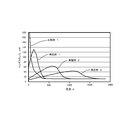
- Example 2 An inductor similar to that in Example 1 was manufactured except that the turns ratio of the coil having the lead wire and the short-circuit coil was set to 10: 3. Inductance was measured by the same method as in Example 1. The results are shown in FIG.
- Example 3 An inductor similar to that in Example 1 was manufactured except that the turns ratio of the coil having the lead wire and the short-circuit coil was set to 10: 5. Inductance was measured by the same method as in Example 1. The results are shown in FIG.
- Comparative Example 1 An inductor similar to that in Example 1 was produced except that no short-circuiting coil was disposed. Inductance was measured by the same method as in Example 1. The results are shown in FIG.
- each example has a short-circuiting coil, so that the inductance is small when the current is small, but the inductance increases as the current increases.
- the inductance peak changes to the high current side.
- the kind of the magnetic material is not particularly limited, and the same tendency can be observed with the materials described in Japanese Patent No. 4763609, Japanese Patent No. 5069962, and Japanese Patent Application No. 2014-62230.
- Example 4 The inductor used in Example 4 is shown in FIG.
- FIG. 4 is a plan view of the inductor.
- the short-circuit coil 4 ′ electrically connected the coil winding start and winding end.
- the coupling coefficient K was set to 0.2 at 700 A by adjusting the wire diameter of the short-circuit coil 4 ′, the turn ratio of the main coil 2 ′ and the short-circuit coil 4 ′, and the number of turns of each.
- Comparative Example 2 An inductor similar to that in Example 4 was produced except that no short-circuiting coil was disposed. The change in current was measured by the same method as in Example 4. The results are shown in FIG.
- the inductor of Example 4 exhibited a current limiting effect that suppressed current increase at a point in time when an arbitrary current value was exceeded after quickly increasing the current in the initial stage.
- the current waveform can be controlled so that the short circuit current does not become too large while rapidly increasing the current value for the circuit breaker operation.
- Comparative Example 2 which is an inductor having a general form that does not have a short-circuit coil, magnetic saturation occurred when the current exceeded several tens of amperes, a significant current increase started, and the current waveform could not be controlled.
- the inductor of the present invention Since the inductor of the present invention has a built-in short-circuit coil at a predetermined position, it can be used as an inductor for electric equipment that is used without being magnetically saturated under a large current. Further, by using the DC circuit protection circuit for the inductor of the present invention, the circuit breaker can be used more safely as a fuse replacement.
Abstract
Provided are an inductor with which it is possible to suppress a decrease in inductance without causing magnetic saturation of a magnetic core even under a large current of the order of several 1000 A, such as a surge current, and a protection circuit using the inductor. The inductor comprises an iron-based magnetic core 3 incorporating a main coil 2, with a short-circuited coil 4, in which a coil—winding start is short-circuited to a coil-winding end, disposed in the magnetic core 3 concentrically with the main coil 2, the short-circuited coil having the effect of cancelling out a magnetic field created by an applied current which is applied to the main coil 2, wherein the magnetic core 3 comprises magnetic cores of the same shape which abut one another at an abutting plane 5. The protection circuit comprises a circuit breaker connected between a direct-current power supply and a load, with a current-limiting inductor connected in series with the circuit breaker.
Description
本発明はインダクタおよび保護回路に関し、特に大電流および高磁化力下におけるトランス、リアクトル、チョークコイル、フィルタ、センサ等のインダクタおよびこのインダクタを用いた保護回路に関する。
The present invention relates to an inductor and a protection circuit, and more particularly to an inductor such as a transformer, a reactor, a choke coil, a filter, and a sensor under a large current and a high magnetizing force, and a protection circuit using the inductor.
近年、スイッチング素子やダイオード等のパワー半導体の機能向上に伴い、回路に流れる電流は大電流、高周波数化してきている。これに伴い回路中で使用されるリアクトルやチョークコイル、トランス等のインダクタについても大電流、高周波数化への対応が求められている。
また太陽光発電や風力発電用のコンバータ、データセンター等の大電流を扱う用途も拡大してきており、これら機器はサージ電流と呼ばれる、雷等の瞬時の大電流ノイズへの対策も重要になってきている。
従来のインダクタは巻線の内側に磁心を挿入することで、発生磁束量を増加させ、漏れ磁束量を減らすことで、インダクタの小型化、高効率化を実現している。 In recent years, with the improvement of functions of power semiconductors such as switching elements and diodes, the current flowing in the circuit has been increased in current and frequency. Along with this, the inductors such as reactors, choke coils, and transformers used in the circuit are also required to cope with high current and high frequency.
Applications that handle large currents such as converters for solar power generation and wind power generation, data centers, etc. are also expanding, and for these devices, countermeasures against instantaneous large current noise such as lightning, which is called surge current, are becoming important. ing.
In the conventional inductor, a magnetic core is inserted inside the winding to increase the amount of generated magnetic flux and reduce the amount of leakage magnetic flux, thereby realizing downsizing and high efficiency of the inductor.
一方、電源線やアース線などの導体線に重畳したノイズ電流を導体線と巻線間の電磁誘導により、そのノイズ電力の一部を巻線側回路に配された抵抗で消費すると共に導体線に重畳するノイズ電流を抑制することにより、医療機器やコンピュータ制御精密電子装置に生じるノイズ障害を低減するノイズ減衰器として、筒状コアに高周波領域においても損失の少ないフェライト材を用い、筒状コアの中空部を貫通した巻線を巻き付け、その巻線にインピーダンス素子を配しているノイズ減衰器が知られている(特許文献1)。
On the other hand, a noise current superimposed on a conductor line such as a power supply line and a ground line is consumed by a resistor arranged in the circuit on the winding side and a part of the noise power is consumed by electromagnetic induction between the conductor line and the winding, and the conductor line. As a noise attenuator that reduces noise disturbances occurring in medical equipment and computer-controlled precision electronic devices by suppressing the noise current superimposed on the cylindrical core, the cylindrical core uses a ferrite material with low loss even in the high-frequency region. There is known a noise attenuator in which a winding penetrating a hollow portion is wound and an impedance element is arranged in the winding (Patent Document 1).
また、電気機器では短絡や漏電等の電気事故からの装置や人の保護が必要であり、保護のために用いる機器は必要時に迅速に動作する必要がある。一方、電気機器では、スイッチや回路遮断器のON/OFF操作時や瞬停発生時に突入電流が発生するが、これらの保護器が突入電流で誤作動しないようにする必要もある。このような相反する要求を満足させるために、ヒューズや回路遮断器、リレーといった各種保護機器が回路の仕様に合わせて使用されている。
Also, electrical equipment needs to protect equipment and people from electrical accidents such as short circuits and leakage, and equipment used for protection needs to operate quickly when necessary. On the other hand, in an electric device, an inrush current is generated when an ON / OFF operation of a switch or a circuit breaker or an instantaneous power failure occurs, but it is also necessary to prevent these protectors from malfunctioning due to the inrush current. In order to satisfy such conflicting requirements, various protective devices such as fuses, circuit breakers, and relays are used in accordance with circuit specifications.
上記保護機器の中で、特にヒューズは動作すると溶断により破損することから、交換のための予備品と交換作業が必要となるため、ヒューズ以外の保護機器を使用したいというニーズがある。
交換の必要のない回路遮断器やリレーは、電磁石や材料の熱変形等を利用して機械的にスイッチを動作させるためヒューズに比べると迅速な遮断が困難である。迅速に動作させるには電流値を高める必要があった。このことから短絡に対して回路遮断器やリレーを用いた場合には、ヒューズに比べて遮断されるまでに時間を要することもあり、保護すべき回路に大きな短絡電流が流れてしまい装置等を保護できない恐れがある。このようなことから、一般に、特に数百ボルト以上の高電圧の直流回路では短絡保護器としてヒューズが多く利用されている。
このような用途でヒューズの代替として回路遮断器を利用するためには、回路に流れる短絡電流があまり大きな値にならないうちに遮断する、もしくは遮断されるまでの間に短絡電流が大きくなり過ぎないように抑制する必要がある。このため、短絡による突入電流が遮断器の定格電流を超えにくくするために、限流コイルと呼ばれるインダクタを直列に接続する方法が知られている(例えば非特許文献1、特許文献2)。 Among the above protective devices, the fuse is damaged by fusing especially when it operates, so that a spare part for replacement and replacement work are necessary, and there is a need to use a protective device other than the fuse.
Circuit breakers and relays that do not require replacement are difficult to cut off quickly compared to fuses because switches are mechanically operated using thermal deformation of electromagnets and materials. In order to operate quickly, it was necessary to increase the current value. Therefore, when a circuit breaker or relay is used against a short circuit, it may take time to be interrupted compared to a fuse, and a large short-circuit current will flow in the circuit to be protected. There is a risk that it cannot be protected. For this reason, in general, fuses are often used as short circuit protectors, particularly in high voltage DC circuits of several hundred volts or more.
In order to use a circuit breaker as an alternative to a fuse in such an application, the short circuit current flowing in the circuit is cut off before the value becomes too large, or the short circuit current does not become too large before it is cut off. Need to be suppressed. For this reason, in order to make the inrush current due to a short circuit difficult to exceed the rated current of the circuit breaker, a method of connecting inductors called current limiting coils in series is known (for example, Non-PatentDocument 1 and Patent Document 2).
交換の必要のない回路遮断器やリレーは、電磁石や材料の熱変形等を利用して機械的にスイッチを動作させるためヒューズに比べると迅速な遮断が困難である。迅速に動作させるには電流値を高める必要があった。このことから短絡に対して回路遮断器やリレーを用いた場合には、ヒューズに比べて遮断されるまでに時間を要することもあり、保護すべき回路に大きな短絡電流が流れてしまい装置等を保護できない恐れがある。このようなことから、一般に、特に数百ボルト以上の高電圧の直流回路では短絡保護器としてヒューズが多く利用されている。
このような用途でヒューズの代替として回路遮断器を利用するためには、回路に流れる短絡電流があまり大きな値にならないうちに遮断する、もしくは遮断されるまでの間に短絡電流が大きくなり過ぎないように抑制する必要がある。このため、短絡による突入電流が遮断器の定格電流を超えにくくするために、限流コイルと呼ばれるインダクタを直列に接続する方法が知られている(例えば非特許文献1、特許文献2)。 Among the above protective devices, the fuse is damaged by fusing especially when it operates, so that a spare part for replacement and replacement work are necessary, and there is a need to use a protective device other than the fuse.
Circuit breakers and relays that do not require replacement are difficult to cut off quickly compared to fuses because switches are mechanically operated using thermal deformation of electromagnets and materials. In order to operate quickly, it was necessary to increase the current value. Therefore, when a circuit breaker or relay is used against a short circuit, it may take time to be interrupted compared to a fuse, and a large short-circuit current will flow in the circuit to be protected. There is a risk that it cannot be protected. For this reason, in general, fuses are often used as short circuit protectors, particularly in high voltage DC circuits of several hundred volts or more.
In order to use a circuit breaker as an alternative to a fuse in such an application, the short circuit current flowing in the circuit is cut off before the value becomes too large, or the short circuit current does not become too large before it is cut off. Need to be suppressed. For this reason, in order to make the inrush current due to a short circuit difficult to exceed the rated current of the circuit breaker, a method of connecting inductors called current limiting coils in series is known (for example, Non-Patent
しかしながら、巻線コイルの内側に磁心を配置しているインダクタの場合、磁心が磁気飽和しないようギャップを設ける、磁性コアの形状を大きくするなど、インダクタの形状が大きくなってしまう。また、高磁化力下でも飽和しにくい材料は高価である。さらに、サージ電流に代表される様な、非常に大きな電流がインダクタに流れる場合には、高磁化力下でも飽和しにくい材料であっても、磁心が磁気飽和してしまいインダクタとして機能しなくなる場合がある。特許文献1に記載されているノイズ減衰器の場合、電流の増加に伴い磁化力が高まると、磁束密度が増加して透磁率が減少する。そのため高磁化力下で高インダクタンスを確保することが困難になるという問題がある。
However, in the case of an inductor in which a magnetic core is arranged inside the winding coil, the shape of the inductor becomes large, such as providing a gap so that the magnetic core is not magnetically saturated, or increasing the shape of the magnetic core. In addition, materials that do not easily saturate even under a high magnetizing force are expensive. Furthermore, when a very large current such as a surge current flows through the inductor, even if the material is difficult to saturate even under a high magnetizing force, the magnetic core will be magnetically saturated and will not function as an inductor. There is. In the case of the noise attenuator described in Patent Document 1, when the magnetizing force increases with an increase in current, the magnetic flux density increases and the magnetic permeability decreases. Therefore, there is a problem that it is difficult to ensure a high inductance under a high magnetizing force.
また、電気機器の保護回路において、限流コイルと呼ばれるインダクタを回路遮断器とともに直列に接続する方法の場合、回路遮断器が動作するまでの時間が長くなるという問題がある。
Also, in the protection circuit for electrical equipment, there is a problem that the time until the circuit breaker operates becomes long when the inductor called a current limiting coil is connected in series with the circuit breaker.
本発明は、このような問題に対処するためになされたものであり、サージ電流のような数1000Aにも及ぶ大電流下でも、磁心を磁気飽和させることなく、高電流下でもインダクタスの低下を抑えることができるインダクタの提供を目的とする。
また、本発明の他の目的は、直流回路において短絡発生初期に、回路遮断器が動作するまでの時間を短くするために、迅速に電流値を大きくしながらも、短絡電流が大きくなり過ぎないように電流波形を制御できる回路遮断用インダクタを用いた保護回路の提供を目的とする。 The present invention has been made to cope with such a problem. Even under a large current of several thousand A such as a surge current, the inductance is reduced even under a high current without magnetic saturation of the magnetic core. An object of the present invention is to provide an inductor capable of suppressing the above.
Another object of the present invention is to shorten the time until the circuit breaker operates in the initial stage of occurrence of a short circuit in a DC circuit, so that the short circuit current does not become too large while rapidly increasing the current value. An object of the present invention is to provide a protection circuit using a circuit interrupting inductor capable of controlling the current waveform.
本発明のインダクタは、主コイルを内蔵する磁性コアからなるインダクタであって、上記主コイルに印加される電流が作る磁界を打ち消す作用を有する短絡コイルを備えていることを特徴とする。特に短絡コイルが主コイルと同心に配置されていることを特徴とする。上記短絡コイルは、コイル巻始めと巻終わりとが、短絡、もしくは微小な抵抗を介して接続されているコイルであることを特徴とする。また、上記磁性コアが鉄系の磁性体であることを特徴とする。
The inductor of the present invention is an inductor comprising a magnetic core with a built-in main coil, and is characterized by comprising a short-circuited coil having an action of canceling out a magnetic field generated by a current applied to the main coil. In particular, the short-circuit coil is arranged concentrically with the main coil. The short-circuited coil is a coil in which a coil winding start and a winding end are connected through a short circuit or a minute resistance. The magnetic core is an iron-based magnetic body.
本発明の保護回路は、直流電源と負荷との間に回路遮断器が接続されている直流回路に用いられ、上記回路遮断器に限流用のインダクタが直列に接続されている保護回路である。この保護回路において、上記限流用のインダクタが本発明のインダクタであることを特徴とする。特にこの限流用のインダクタは、主コイルと短絡コイルとの間の結合係数Kが印加電流の増加に伴い低下することを特徴とする。また、印加電流の増加に伴い低下する結合係数Kの低下する割合α(α=-dK/dA)がK=0.5を境にして、Kが0.5超のαより大きくなることを特徴とする。
The protection circuit of the present invention is a protection circuit used in a DC circuit in which a circuit breaker is connected between a DC power supply and a load, and a current-limiting inductor is connected in series to the circuit breaker. In this protection circuit, the current limiting inductor is the inductor of the present invention. In particular, the current-limiting inductor is characterized in that the coupling coefficient K between the main coil and the short-circuit coil decreases as the applied current increases. Further, the ratio α (α = −dK / dA) at which the coupling coefficient K that decreases as the applied current increases decreases from K = 0.5 to K that is greater than α exceeding 0.5. Features.
本発明のインダクタは、主コイルに印加される印加電流が作る磁界を打ち消す作用を有する短絡コイルが上記主コイルと同心に配置されているので、以下の作用効果が得られる。
(1)磁性コアに発生する磁化力を減らすことができる。
(2)結合係数、短絡コイルの巻き数、短絡コイルの直流抵抗値等により短絡コイルに発生する磁化力を制御することができる。これにより使用電流下における透磁率を制御し、高いインダクタンスを保持させることができる。
(3)低磁化力下でしか高い透磁率を得られないフェライト等の安価な材料を用いた場合でも、高電流下でも発生磁化力を低減できることから、高い透磁率、および高いインダクタンスを持つことができる。
(4)高電流下でも高い透磁率を得られるため、小さい形状のインダクタの設計が可能となる。これらによりたとえば、サージ電流のような数1000Aにも及ぶ大電流下でも、安価な材料を用いる小さな形状のインダクタであっても、高いインダクタンスを確保できるようになる。 In the inductor according to the present invention, the short-circuiting coil having the function of canceling out the magnetic field generated by the applied current applied to the main coil is disposed concentrically with the main coil, so that the following effects can be obtained.
(1) Magnetization force generated in the magnetic core can be reduced.
(2) The magnetizing force generated in the short circuit coil can be controlled by the coupling coefficient, the number of turns of the short circuit coil, the DC resistance value of the short circuit coil, and the like. As a result, the magnetic permeability under the operating current can be controlled and high inductance can be maintained.
(3) Even when using an inexpensive material such as ferrite that can only obtain a high magnetic permeability only under a low magnetic force, the generated magnetic force can be reduced even under a high current, so that it has a high magnetic permeability and a high inductance. Can do.
(4) Since a high magnetic permeability can be obtained even under a high current, a small inductor can be designed. Thus, for example, even under a large current of several thousand A such as a surge current, a high inductance can be secured even with a small-shaped inductor using an inexpensive material.
本発明の保護回路は、回路遮断器に限流用のインダクタが直列に接続されている。このインダクタは主コイルに印加される印加電流が作る磁界を打ち消す作用を有する短絡コイルを有しているので、直流回路における短絡発生初期に、回路遮断器が動作するまでの時間を短くできる。また、遮断器の瞬時動作モード等の迅速に遮断器を動作させることが可能な電流を遮断器の電磁石用コイルに供給することができ、かつ必要な電流値を超えてからの電流増加を抑制することができる。本発明の保護回路を用いることで、直流回路においてヒューズ代替として回路遮断器がより安全に使用できるようになる。
In the protection circuit of the present invention, a current limiting inductor is connected in series to the circuit breaker. Since this inductor has a short-circuited coil that has the effect of canceling the magnetic field generated by the applied current applied to the main coil, the time until the circuit breaker operates can be shortened at the initial stage of occurrence of a short circuit in the DC circuit. In addition, the current that can operate the circuit breaker quickly, such as the instantaneous operation mode of the circuit breaker, can be supplied to the electromagnet coil of the circuit breaker, and the increase in current after the required current value is exceeded is suppressed. can do. By using the protection circuit of the present invention, a circuit breaker can be used more safely as a substitute for a fuse in a DC circuit.
本発明に係るインダクタの一例を図1に示す。図1(a)はポット型インダクタの斜視図であり、図1(b)はA-A断面図である。コイルからの引き出し線は図示を省略してある。
インダクタ1は、円筒形磁性コア3内に引き出し線の図示が省略された主コイル2が内蔵されている。この主コイル2による磁界を打ち消す作用を有する短絡コイル4が主コイル2と同心に、かつ主コイル2の内側に配置されている。なお、短絡コイル4は同心であれば主コイル2の外側であってもよい。本発明において、同心に配置とは、巻回されているコイルのコイル中心軸の方向が略同一方向に配置されていることを表す。好ましくはコイル中心軸の方向が同一である。また、同心に配置とは、巻回されているコイルのコイル中心軸を通る磁力線の方向が順方向または逆方向で略同一方向になるように、主コイルおよび短絡コイルが磁性コア内に配置されている場合も含む。5は磁性コア3の製造時における衝合面である。 An example of the inductor according to the present invention is shown in FIG. FIG. 1A is a perspective view of a pot type inductor, and FIG. 1B is a cross-sectional view taken along line AA. The lead wire from the coil is not shown.
Theinductor 1 includes a main coil 2 in which a lead wire is not shown in a cylindrical magnetic core 3. A short-circuit coil 4 having an action of canceling the magnetic field generated by the main coil 2 is disposed concentrically with the main coil 2 and inside the main coil 2. The short-circuit coil 4 may be outside the main coil 2 as long as it is concentric. In the present invention, the concentric arrangement means that the directions of the coil central axes of the wound coils are arranged in substantially the same direction. Preferably, the directions of the coil central axes are the same. Concentric arrangement means that the main coil and the short-circuit coil are arranged in the magnetic core so that the direction of the lines of magnetic force passing through the coil central axis of the coil being wound is substantially the same in the forward direction or the reverse direction. This includes cases where Reference numeral 5 denotes an abutting surface when the magnetic core 3 is manufactured.
インダクタ1は、円筒形磁性コア3内に引き出し線の図示が省略された主コイル2が内蔵されている。この主コイル2による磁界を打ち消す作用を有する短絡コイル4が主コイル2と同心に、かつ主コイル2の内側に配置されている。なお、短絡コイル4は同心であれば主コイル2の外側であってもよい。本発明において、同心に配置とは、巻回されているコイルのコイル中心軸の方向が略同一方向に配置されていることを表す。好ましくはコイル中心軸の方向が同一である。また、同心に配置とは、巻回されているコイルのコイル中心軸を通る磁力線の方向が順方向または逆方向で略同一方向になるように、主コイルおよび短絡コイルが磁性コア内に配置されている場合も含む。5は磁性コア3の製造時における衝合面である。 An example of the inductor according to the present invention is shown in FIG. FIG. 1A is a perspective view of a pot type inductor, and FIG. 1B is a cross-sectional view taken along line AA. The lead wire from the coil is not shown.
The
主コイル2を構成する巻線としては銅エナメル線を使用することができ、その種類としてはウレタン線(UEW)、ホルマール線(PVF)、ポリエステル線(PEW)、ポリエステルイミド線(EIW)、ポリアミドイミド線(AIW)、ポリイミド線(PIW)、これらを組み合わせた二重被複線、または自己融着線、リッツ線等を使用できる。銅エナメル線の断面形状としては丸線や角線を使用できる。特に、平角線の断面形状の短径側を磁性コアに接して重ね巻きすることにより、巻線密度を向上させたコイルが得られる。
A copper enameled wire can be used as the winding constituting the main coil 2, and the types thereof are urethane wire (UEW), formal wire (PVF), polyester wire (PEW), polyesterimide wire (EIW), polyamide. An imide wire (AIW), a polyimide wire (PIW), a double coated wire combining these, a self-bonding wire, a litz wire, or the like can be used. A round wire or a square wire can be used as the cross-sectional shape of the copper enamel wire. In particular, a coil having an improved winding density can be obtained by overlappingly winding the short axis side of the cross-sectional shape of the rectangular wire in contact with the magnetic core.
主コイル2は樹脂に埋設して一体化することが好ましい。主コイル2を埋設する樹脂体としては、主コイル2を固定し、絶縁性を付与できる樹脂であれば使用できる。好ましくは、ポッティングや注入により樹脂封止可能なエポキシ樹脂やシリコーン樹脂等の熱硬化性樹脂、射出成形が可能な熱可塑性樹脂を使用できる。熱可塑性樹脂としては、ポリエチレン、ポリプロピレン等のポリオレフィン、ポリビニルアルコール、ポリエチレンオキサイド、ポリフェニレンサルファイド(PPS)、液晶ポリマー、ポリエーテルエーテルケトン(PEEK)、ポリイミド、ポリエーテルイミド、ポリアセタール、ポリエーテルサルホン、ポリサルホン、ポリカーボネート、ポリエチレンテレフタレート、ポリブチレンテレフタレート、ポリフェニレンオキサイド、ポリフタールアミド、ポリアミド、これらの混合物が挙げられる。これらの中で、射出成形時の流動性に優れ、射出成形後の成形体の表面を樹脂層で覆うことができると共に、耐熱性などに優れるポリフェニレンサルファイド(PPS)が好ましい。
The main coil 2 is preferably embedded in resin and integrated. As the resin body in which the main coil 2 is embedded, any resin that can fix the main coil 2 and impart insulation can be used. Preferably, a thermosetting resin such as an epoxy resin or silicone resin that can be sealed by potting or injection, or a thermoplastic resin that can be injection-molded can be used. Thermoplastic resins include polyolefins such as polyethylene and polypropylene, polyvinyl alcohol, polyethylene oxide, polyphenylene sulfide (PPS), liquid crystal polymer, polyether ether ketone (PEEK), polyimide, polyether imide, polyacetal, polyether sulfone, and polysulfone. , Polycarbonate, polyethylene terephthalate, polybutylene terephthalate, polyphenylene oxide, polyphthalamide, polyamide, and mixtures thereof. Among these, polyphenylene sulfide (PPS), which has excellent fluidity during injection molding, can cover the surface of the molded article after injection molding with a resin layer, and is excellent in heat resistance and the like, is preferable.
射出成形は、例えば可動型および固定型が衝合され、内部に主コイル2が載置されたコイルの金型内に樹脂体を射出して成形する方法を用いることができる。射出成形条件としては熱可塑性樹脂の種類によっても異なるが、例えばポリフェニレンサルファイド(PPS)の場合、樹脂温度が290~350℃、金型温度が100~150℃であることが好ましい。
Injection molding can be performed by, for example, a method in which a movable mold and a fixed mold are abutted and a resin body is injected into a mold of a coil in which the main coil 2 is placed. The injection molding conditions vary depending on the type of thermoplastic resin. For example, in the case of polyphenylene sulfide (PPS), the resin temperature is preferably 290 to 350 ° C. and the mold temperature is preferably 100 to 150 ° C.
主コイル2を埋設する樹脂体としては、上記熱可塑性樹脂以外に、磁性コア3の結着材として使用されるエポキシ樹脂、またはフェノール樹脂等の熱硬化性樹脂を使用できる。
As the resin body in which the main coil 2 is embedded, in addition to the thermoplastic resin, an epoxy resin used as a binder for the magnetic core 3 or a thermosetting resin such as a phenol resin can be used.
短絡コイル4は、コイル巻始めと巻終わりとが短絡されているコイルであれば使用することができる。また、短絡コイル4は、主コイル2と同心に配置されていることが好ましい。同心に配置することにより、主コイル2の通電により発生する磁界が短絡コイル4に作用して、該磁界を効率的に打ち消すことができる。また、コイルの巻数、銅線の径、さらに主コイル2と短絡コイル4との遠近配置による結合係数を変化させることにより短絡コイル4に発生する磁化力を制御できる。これにより主コイル2に印加される電流下における磁性コア3の透磁率を制御し、高電流下においても高いインダクタンスを保持できるインダクタが得られる。
The short-circuit coil 4 can be used as long as the coil winding start and winding end are short-circuited. The short-circuit coil 4 is preferably arranged concentrically with the main coil 2. By arranging them concentrically, the magnetic field generated by energization of the main coil 2 acts on the short-circuiting coil 4, and the magnetic field can be canceled out efficiently. Moreover, the magnetizing force which generate | occur | produces in the short circuit coil 4 is controllable by changing the coupling coefficient by the number of turns of a coil, the diameter of a copper wire, and the perspective arrangement of the main coil 2 and the short circuit coil 4. FIG. Thereby, the magnetic permeability of the magnetic core 3 under the current applied to the main coil 2 is controlled, and an inductor that can maintain a high inductance even under a high current is obtained.
短絡コイル4を構成する巻線としては、主コイル2と同様の巻線を使用することができる。また、導体で造られた円筒物も短絡コイルとして利用できる。短絡コイル4は、主コイル2と同様に樹脂で埋設して一体化することが好ましい。
As the winding constituting the short-circuit coil 4, the same winding as the main coil 2 can be used. Moreover, the cylindrical thing made with the conductor can also be utilized as a short circuit coil. The short-circuit coil 4 is preferably embedded and integrated with resin in the same manner as the main coil 2.
磁性コア3は鉄系の磁性体であることが好ましい。鉄系の磁性体としては、例えば、純鉄、鉄-シリコン系合金、鉄-窒素系合金、鉄-ニッケル系合金、鉄-炭素系合金、鉄-ホウ素系合金、鉄-コバルト系合金、鉄-リン系合金、鉄-ニッケル-コバルト系合金および鉄-アルミニウム-シリコン系合金(センダスト合金)、鉄アモルファス系材料、微細結晶材料などの粉末表面を絶縁処理し、圧縮成形して製造することができる。これら磁性体粉末の中でも、純鉄が好ましく、特に粉末冶金に用いられている還元鉄粉またはアトマイズ鉄粉が好ましい。また、コスト面と絶縁被膜処理のしやすさから、水アトマイズ鉄粉が好ましい。
The magnetic core 3 is preferably an iron-based magnetic material. Examples of iron-based magnetic materials include pure iron, iron-silicon alloys, iron-nitrogen alloys, iron-nickel alloys, iron-carbon alloys, iron-boron alloys, iron-cobalt alloys, iron -It can be manufactured by insulating and compressing powder surfaces of phosphorus alloys, iron-nickel-cobalt alloys and iron-aluminum-silicon alloys (Sendust alloys), iron amorphous materials, fine crystal materials, etc. it can. Among these magnetic powders, pure iron is preferable, and reduced iron powder or atomized iron powder used in powder metallurgy is particularly preferable. Moreover, water atomized iron powder is preferable from the viewpoint of cost and ease of treatment of the insulating coating.
上記磁性体粉末粒子の表面は無機絶縁体で被覆されていることが好ましい。無機絶縁材料の種類に特に限定はなく、従来から圧粉磁心において用いられているものを使用することができる。好ましい絶縁材料の例としては、リン酸鉄、リン酸マンガン、リン酸亜鉛、リン酸カルシウム、リン酸アルミニウム等のリン酸金属塩、酸化ケイ素、酸化マグネシウム、酸化アルミニウム、酸化チタン、酸化ジルコニウム等の金属酸化物が挙げられる。無機絶縁体で被覆されている鉄系軟磁性体粉末の市販品としては、ヘガネス社製商品名;Somaloyが挙げられる。
The surface of the magnetic powder particles is preferably coated with an inorganic insulator. There is no limitation in particular in the kind of inorganic insulating material, The thing conventionally used in the dust core can be used. Examples of preferable insulating materials include metal phosphates such as iron phosphate, manganese phosphate, zinc phosphate, calcium phosphate, and aluminum phosphate, metal oxides such as silicon oxide, magnesium oxide, aluminum oxide, titanium oxide, and zirconium oxide. Things. As a commercial product of iron-based soft magnetic powder coated with an inorganic insulator, there is a trade name manufactured by Höganäs; Somaloy.
磁性コア3となる磁性体は、例えば、粒子表面に絶縁被覆が形成された上記原料粉末単体、または上記原料粉末にエポキシ樹脂などの熱硬化性樹脂が配合された粉末を加圧成形して圧粉体とし、この圧粉体を焼成して製造できる。エポキシ樹脂などの熱硬化性樹脂は、強度面で問題が生じるおそれがある場合に配合する。
The magnetic material to be the magnetic core 3 is formed by, for example, pressing the raw material powder having an insulating coating on the particle surface, or a powder in which a thermosetting resin such as an epoxy resin is blended into the raw material powder. It can be manufactured by baking this green compact into powder. Thermosetting resins such as epoxy resins are blended when there is a risk of problems in strength.
本発明に使用できるエポキシ樹脂は、接着用エポキシ樹脂として使用できる樹脂であって軟化温度が100~120℃の樹脂が好ましい。例えば、室温では固体であるが、50~60℃でペースト状になり、130~140℃で流動性になり、さらに加熱を続けると硬化反応が始まるエポキシ樹脂であれば使用できる。この硬化反応は120℃付近でも始まるが、実用的な硬化時間、例えば2時間以内で硬化反応が終了する温度としては170~190℃であることが好ましい。この温度範囲であると、硬化時間は45~80分である。
The epoxy resin that can be used in the present invention is a resin that can be used as an adhesive epoxy resin and preferably has a softening temperature of 100 to 120 ° C. For example, an epoxy resin that is solid at room temperature, becomes a paste at 50 to 60 ° C., becomes fluid at 130 to 140 ° C., and starts a curing reaction when further heated can be used. This curing reaction starts even at around 120 ° C., but the temperature at which the curing reaction is completed within a practical curing time, for example within 2 hours, is preferably 170 to 190 ° C. In this temperature range, the curing time is 45 to 80 minutes.
エポキシ樹脂の樹脂成分としては、例えばビスフェノールA型エポキシ樹脂、ビスフェノールF型エポキシ樹脂、ビスフェノールS型エポキシ樹脂、水添ビスフェノールA型エポキシ樹脂、水添ビスフェノールF型エポキシ樹脂、スチルベン型エポキシ樹脂、トリアジン骨格含有エポキシ樹脂、フルオレン骨格含有エポキシ樹脂、脂環式エポキシ樹脂、ノボラック型エポキシ樹脂、アクリルエポキシ樹脂、グリシジルアミン型エポキシ樹脂、トリフェノールフェノールメタン型エポキシ樹脂、アルキル変性トリフェノールメタン型エポキシ樹脂、ビフェニル型エポキシ樹脂、ジシクロペンタジエン骨格含有エポキシ樹脂、ナフタレン骨格含有エポキシ樹脂、アリールアルキレン型エポキシ樹脂等が挙げられる。
Examples of the resin component of the epoxy resin include bisphenol A type epoxy resin, bisphenol F type epoxy resin, bisphenol S type epoxy resin, hydrogenated bisphenol A type epoxy resin, hydrogenated bisphenol F type epoxy resin, stilbene type epoxy resin, and triazine skeleton. -Containing epoxy resin, fluorene skeleton-containing epoxy resin, alicyclic epoxy resin, novolac-type epoxy resin, acrylic epoxy resin, glycidylamine-type epoxy resin, triphenolphenolmethane-type epoxy resin, alkyl-modified triphenolmethane-type epoxy resin, biphenyl-type Examples thereof include an epoxy resin, a dicyclopentadiene skeleton-containing epoxy resin, a naphthalene skeleton-containing epoxy resin, and an arylalkylene type epoxy resin.
エポキシ樹脂の硬化剤成分は潜在性エポキシ硬化剤が好ましい。潜在性エポキシ硬化剤を用いることにより、軟化温度を100~120℃に、また硬化温度を170~190℃に設定することができ、鉄粉粉末への絶縁性塗膜の形成と、その後の圧縮成形および熱硬化を行なうことができる。
潜在性エポキシ硬化剤としては、ジシアンジアミド、三フッ化ホウ素-アミン錯体、有機酸ヒドラジド等が挙げられる。これらの中で、上記硬化条件に適合するジシアンジアミドが好ましい。
また、潜在性エポキシ硬化剤と共に、三級アミン、イミダゾール、芳香族アミンなどの硬化促進剤を含むことができる。
なお、上記潜在性硬化剤を含むエポキシ樹脂は、160℃で2時間、170℃で80分、180℃で55分、190℃で45分、200℃で30分の硬化条件となるように潜在性硬化剤を配合する。 The curing agent component of the epoxy resin is preferably a latent epoxy curing agent. By using a latent epoxy curing agent, the softening temperature can be set to 100 to 120 ° C, and the curing temperature can be set to 170 to 190 ° C. Formation of an insulating coating on iron powder and subsequent compression Molding and thermosetting can be performed.
Examples of the latent epoxy curing agent include dicyandiamide, boron trifluoride-amine complex, and organic acid hydrazide. Of these, dicyandiamide that meets the above-mentioned curing conditions is preferred.
Moreover, hardening accelerators, such as tertiary amine, an imidazole, and an aromatic amine, can be included with a latent epoxy hardening | curing agent.
The epoxy resin containing the latent curing agent is latent so that the curing conditions are 160 ° C. for 2 hours, 170 ° C. for 80 minutes, 180 ° C. for 55 minutes, 190 ° C. for 45 minutes, and 200 ° C. for 30 minutes. Add a functional curing agent.
エポキシ樹脂を配合する場合、表面が無機絶縁被膜処理された鉄系軟磁性体粉末とエポキシ樹脂の配合割合は、これらの合計量に対して、鉄系軟磁性体粉末が95~99質量%、潜在性硬化剤を含むエポキシ樹脂が1~5質量%である。エポキシ樹脂が1質量%未満であると、強度面の所望の向上が望めず、5質量%を超えると磁気特性の低下と樹脂リッチな粗大な凝集体が発生するからである。
When the epoxy resin is blended, the blending ratio of the iron-based soft magnetic powder whose surface is treated with the inorganic insulating coating and the epoxy resin is 95 to 99% by mass of the iron-based soft magnetic powder with respect to the total amount of these. The epoxy resin containing the latent curing agent is 1 to 5% by mass. If the epoxy resin is less than 1% by mass, the desired improvement in strength cannot be expected, and if it exceeds 5% by mass, a decrease in magnetic properties and a resin-rich coarse aggregate are generated.
エポキシ樹脂を配合した磁性体は、上記表面が無機絶縁被膜処理された鉄系軟磁性体粉末と、上記エポキシ樹脂とを100~120℃の温度で乾式混合することで、鉄系軟磁性体粉末表面に形成された無機絶縁被膜上に未硬化樹脂被膜を形成する。絶縁被膜が表面に形成された鉄系軟磁性体粉末は、金型を用いる圧縮成形により成形体となし、その後エポキシ樹脂の熱硬化開始温度以上の温度で熱硬化させることで一体化された磁性体が得られる。
The magnetic material blended with the epoxy resin is obtained by dry-mixing the iron-based soft magnetic material powder whose surface is treated with an inorganic insulating coating and the epoxy resin at a temperature of 100 to 120 ° C. An uncured resin film is formed on the inorganic insulating film formed on the surface. An iron-based soft magnetic powder with an insulating coating formed on its surface is formed into a compact by compression molding using a mold, and then heat-cured at a temperature equal to or higher than the thermal curing start temperature of the epoxy resin. The body is obtained.
また、磁性コア3となる磁性体は、鉄系軟磁性体粉末に結着樹脂を配合して、この混合物を射出成形することによっても製造できる。結着樹脂としては、射出成形が可能な熱可塑性樹脂を使用できる。熱可塑性樹脂としては、上述のコイルを埋設する樹脂体の場合と同じものを使用できる。その中でも、鉄系軟磁性体粉末に混合したときの射出成形時の流動性に優れ、射出成形後の成形体の表面を樹脂層で覆うことができると共に、耐熱性などに優れるポリフェニレンサルファイド(PPS)が好ましい。
原料粉末の割合は、原料粉末と熱可塑性樹脂との合計量を100質量%として、80~95質量%であることが好ましい。80質量%未満であると磁気特性が得られず、95質量%をこえると射出成形性に劣る。
射出成形は、例えば可動型および固定型が衝合された金型内に上記原料粉末を射出して成形する方法を用いることができる。 Moreover, the magnetic body used as themagnetic core 3 can also be manufactured by blending a binder resin with iron-based soft magnetic powder and injection molding the mixture. As the binder resin, a thermoplastic resin capable of injection molding can be used. As a thermoplastic resin, the same thing as the case of the resin body which embeds the above-mentioned coil can be used. Among them, polyphenylene sulfide (PPS) is excellent in fluidity at the time of injection molding when mixed with iron-based soft magnetic powder, the surface of the molded article after injection molding can be covered with a resin layer, and excellent in heat resistance and the like. ) Is preferred.
The ratio of the raw material powder is preferably 80 to 95% by mass, where the total amount of the raw material powder and the thermoplastic resin is 100% by mass. If it is less than 80% by mass, magnetic properties cannot be obtained, and if it exceeds 95% by mass, the injection moldability is poor.
For the injection molding, for example, a method of injecting and molding the raw material powder into a mold in which a movable mold and a fixed mold are abutted can be used.
原料粉末の割合は、原料粉末と熱可塑性樹脂との合計量を100質量%として、80~95質量%であることが好ましい。80質量%未満であると磁気特性が得られず、95質量%をこえると射出成形性に劣る。
射出成形は、例えば可動型および固定型が衝合された金型内に上記原料粉末を射出して成形する方法を用いることができる。 Moreover, the magnetic body used as the
The ratio of the raw material powder is preferably 80 to 95% by mass, where the total amount of the raw material powder and the thermoplastic resin is 100% by mass. If it is less than 80% by mass, magnetic properties cannot be obtained, and if it exceeds 95% by mass, the injection moldability is poor.
For the injection molding, for example, a method of injecting and molding the raw material powder into a mold in which a movable mold and a fixed mold are abutted can be used.
図1に示す本発明のインダクタは、主コイル2および短絡コイル4を図1(b)に示す断面図で上下に2分割された磁性コア3の内部に配置することで得られる。2分割された磁性コア3は衝合面5で相互に無溶剤型のエポキシ系接着剤等を用いて接着される。
The inductor of the present invention shown in FIG. 1 is obtained by disposing the main coil 2 and the short-circuit coil 4 inside a magnetic core 3 that is divided into two vertically in the cross-sectional view shown in FIG. The two divided magnetic cores 3 are bonded to each other at the abutting surface 5 using a solventless epoxy adhesive or the like.
本発明のインダクタは、サージ対策用回路内、短絡防止用回路内、大電流時ノイズフィルタ回路、回路遮断器が接続されている直流回路の保護回路等に使用できる。
The inductor of the present invention can be used in surge protection circuits, short-circuit prevention circuits, high current noise filter circuits, DC circuit protection circuits connected with circuit breakers, and the like.
直流回路の保護回路に用いた場合の一例を図3に示す。図3は保護回路が接続された直流回路の例である。
直流電源6と負荷7との間に、保護回路としての限流用のインダクタ1’、回路遮断器8および負荷7が順に直列に接続されている。本発明で使用される回路遮断器8は完全電磁式の配線遮断器であり、遮断器のリレー部に流れる電流値が大きいほど、遮断までの時間が短くなる特徴をもつ。この回路遮断器8と直列に接続される限流用のインダクタ1’は主コイル2’と磁気的に結合された短絡コイル4’とを有し、主コイル2’を直流のメイン回路に接続して使用する。負荷7などの短絡により直流回路に大きな電流変化が生じると短絡コイル4’が作動する。短絡コイル4’は、直流の遮断回路で利用する回路遮断器8の特性に合わせて1次側の電流値の増加を抑制するもので、具体的には回路遮断器8を所望の時間で動作させる電流値までは、インダクタ1’の影響を軽微に抑えることで迅速に増加させ、任意の電流値を超えてから電流増加を抑制するためのものである。 An example in the case of using for a protection circuit of a DC circuit is shown in FIG. FIG. 3 shows an example of a DC circuit to which a protection circuit is connected.
Between theDC power source 6 and the load 7, a current limiting inductor 1 ′ as a protection circuit, a circuit breaker 8, and a load 7 are sequentially connected in series. The circuit breaker 8 used in the present invention is a complete electromagnetic wiring breaker, and has a feature that the time until the break is shortened as the value of the current flowing through the relay part of the breaker increases. The current limiting inductor 1 'connected in series with the circuit breaker 8 has a main coil 2' and a short-circuit coil 4 'magnetically coupled, and connects the main coil 2' to a DC main circuit. To use. When a large current change occurs in the DC circuit due to a short circuit of the load 7 or the like, the short circuit coil 4 'is activated. The short-circuit coil 4 'suppresses an increase in the primary current value in accordance with the characteristics of the circuit breaker 8 used in the DC breaker circuit. Specifically, the circuit breaker 8 is operated at a desired time. The current value to be increased is quickly increased by slightly suppressing the influence of the inductor 1 ', and the current increase is suppressed after exceeding an arbitrary current value.
直流電源6と負荷7との間に、保護回路としての限流用のインダクタ1’、回路遮断器8および負荷7が順に直列に接続されている。本発明で使用される回路遮断器8は完全電磁式の配線遮断器であり、遮断器のリレー部に流れる電流値が大きいほど、遮断までの時間が短くなる特徴をもつ。この回路遮断器8と直列に接続される限流用のインダクタ1’は主コイル2’と磁気的に結合された短絡コイル4’とを有し、主コイル2’を直流のメイン回路に接続して使用する。負荷7などの短絡により直流回路に大きな電流変化が生じると短絡コイル4’が作動する。短絡コイル4’は、直流の遮断回路で利用する回路遮断器8の特性に合わせて1次側の電流値の増加を抑制するもので、具体的には回路遮断器8を所望の時間で動作させる電流値までは、インダクタ1’の影響を軽微に抑えることで迅速に増加させ、任意の電流値を超えてから電流増加を抑制するためのものである。 An example in the case of using for a protection circuit of a DC circuit is shown in FIG. FIG. 3 shows an example of a DC circuit to which a protection circuit is connected.
Between the
通常のトランス等において結合係数Kは電流値によって変化しないことが重要であるが、本発明に係る限流用のインダクタ1’を構成する主コイル2’と短絡コイル4’との間の結合係数Kは、主コイル2’に流れる電流が大きくなるにつれて低下し、K≦0.5付近において電流増加を急激に遅くできることを見出した(図6参照)。すなわち、結合係数Kの低下する割合α(α=-dK/dA)がK=0.5を境にして、Kが0.5超のαより大きくなることが分かった。その結果、大電流時に電流を抑制する効果は、任意の電流値における結合係数Kの値を0.5以下になるよう限流用のインダクタを設計することで実現できる。なお、αは、磁心の形状、主コイルの巻き数、短絡コイルの巻き数や、コイルの電気抵抗値により任意に制御できる。例えば、短絡コイルの巻き数を増やす、磁気回路の磁気抵抗を下げる、磁心の飽和磁束密度値を高くする、および/または、短絡コイルの数を増やしたり、短絡コイルの線径を大きくして短絡コイルの抵抗値を下げることで、αが急激に変化する電流値を大電流側にシフトすることができる。
In a normal transformer or the like, it is important that the coupling coefficient K does not change depending on the current value. However, the coupling coefficient K between the main coil 2 ′ and the short-circuit coil 4 ′ constituting the current-limiting inductor 1 ′ according to the present invention. Has been found to decrease as the current flowing through the main coil 2 ′ increases, and the current increase can be rapidly delayed in the vicinity of K ≦ 0.5 (see FIG. 6). That is, it has been found that the rate α (α = −dK / dA) at which the coupling coefficient K decreases is greater than α exceeding K of 0.5 at the boundary of K = 0.5. As a result, the effect of suppressing the current at the time of a large current can be realized by designing the current-limiting inductor so that the value of the coupling coefficient K at an arbitrary current value is 0.5 or less. Α can be arbitrarily controlled by the shape of the magnetic core, the number of turns of the main coil, the number of turns of the short-circuit coil, and the electric resistance value of the coil. For example, increase the number of turns of the short circuit coil, decrease the magnetic resistance of the magnetic circuit, increase the saturation magnetic flux density value of the magnetic core, and / or increase the number of short circuit coils or increase the wire diameter of the short circuit coil By reducing the resistance value of the coil, the current value at which α changes abruptly can be shifted to the large current side.
本発明の保護回路は、直流回路において短絡発生初期には、回路遮断器を素早く動作させるために迅速に電流値を大きくしながらも、短絡電流が大きくなり過ぎないように電流波形を制御できるので、EV用急速充電器等のバッテリー充電器、データセンターやスマートハウス等に利用される高圧直流送電システム(HVDC)、太陽光発電等の直流発電機器等に利用できる。
The protection circuit of the present invention can control the current waveform so that the short-circuit current does not become too large while the current value is increased rapidly in order to quickly operate the circuit breaker at the initial stage of occurrence of the short-circuit in the DC circuit. It can be used for battery chargers such as EV quick chargers, high-voltage DC power transmission systems (HVDC) used in data centers, smart houses, etc., and DC generators such as solar power generation.
実施例1
粒子表面が無機絶縁被膜で覆われた鉄粉粒子(ヘガネス社製、Somaloy:絶縁性被膜処理鉄粉)を用いて、図1に示す内部にコイルを配置できる空間部を有するポッド型磁性コア3を作製した。磁性コア3の寸法は内径(t1)28mm、外径(t2)120mm、高さ(t3)36.5mm、空間部の横方向厚さ(t4)12mm、空間部の縦方向厚さ(t5)10mmのポッド型であり、これを2個作製した。 Example 1
A pod typemagnetic core 3 having a space in which a coil can be arranged in the interior shown in FIG. 1 using iron powder particles whose surface is covered with an inorganic insulating film (Somaloy: Insulative film-treated iron powder manufactured by Höganäs). Was made. The dimensions of the magnetic core 3 are an inner diameter (t 1 ) of 28 mm, an outer diameter (t 2 ) of 120 mm, a height (t 3 ) of 36.5 mm, a lateral thickness of the space (t 4 ) of 12 mm, and a vertical thickness of the space. (T 5 ) 10 mm pod type, and two were produced.
粒子表面が無機絶縁被膜で覆われた鉄粉粒子(ヘガネス社製、Somaloy:絶縁性被膜処理鉄粉)を用いて、図1に示す内部にコイルを配置できる空間部を有するポッド型磁性コア3を作製した。磁性コア3の寸法は内径(t1)28mm、外径(t2)120mm、高さ(t3)36.5mm、空間部の横方向厚さ(t4)12mm、空間部の縦方向厚さ(t5)10mmのポッド型であり、これを2個作製した。 Example 1
A pod type
巾と厚みの寸法が5×4.5mmの平角絶縁巻線を準備して、これをエッジワイズ巻きして、コイル寸法が内径80mm、外径90mm、高さ50mmのコイルを作製した。コイルを磁性コア3の一方に配置し、引き出し線を固定した。
一方、上記平角絶縁巻線を用いて、コイル寸法が内径54mm、外径64mm、高さ50mmであり、引き出し線を有するコイル(主コイル2)と短絡コイル(コイル4)の巻数比が10:1となる短絡コイルを作製した。この短絡コイルは、コイル巻始めと巻終わりとを電気的に接続した。この短絡コイルを上記引き出し線を有するコイルの内側に配置し、他方の磁性コア3を用いて、コイル全体を覆い、図1に示すインダクタを作製した。両コイルのコイル間隔(t6)は7mmであった。 A rectangular insulated winding having a width and thickness of 5 × 4.5 mm was prepared, and this was edgewise wound to produce a coil having an inner diameter of 80 mm, an outer diameter of 90 mm, and a height of 50 mm. The coil was placed on one side of themagnetic core 3 and the lead wire was fixed.
On the other hand, using the above-described flat insulated winding, the coil size is 54 mm inside diameter, 64 mm outside diameter, and 50 mm height, and the turn ratio of the coil (main coil 2) having the lead wire and the short-circuit coil (coil 4) is 10: A short-circuit coil to be 1 was produced. This short-circuited coil electrically connected the coil winding start and winding end. The short-circuited coil was placed inside the coil having the lead wire, and the othermagnetic core 3 was used to cover the entire coil to produce the inductor shown in FIG. The coil interval (t 6 ) between both coils was 7 mm.
一方、上記平角絶縁巻線を用いて、コイル寸法が内径54mm、外径64mm、高さ50mmであり、引き出し線を有するコイル(主コイル2)と短絡コイル(コイル4)の巻数比が10:1となる短絡コイルを作製した。この短絡コイルは、コイル巻始めと巻終わりとを電気的に接続した。この短絡コイルを上記引き出し線を有するコイルの内側に配置し、他方の磁性コア3を用いて、コイル全体を覆い、図1に示すインダクタを作製した。両コイルのコイル間隔(t6)は7mmであった。 A rectangular insulated winding having a width and thickness of 5 × 4.5 mm was prepared, and this was edgewise wound to produce a coil having an inner diameter of 80 mm, an outer diameter of 90 mm, and a height of 50 mm. The coil was placed on one side of the
On the other hand, using the above-described flat insulated winding, the coil size is 54 mm inside diameter, 64 mm outside diameter, and 50 mm height, and the turn ratio of the coil (main coil 2) having the lead wire and the short-circuit coil (coil 4) is 10: A short-circuit coil to be 1 was produced. This short-circuited coil electrically connected the coil winding start and winding end. The short-circuited coil was placed inside the coil having the lead wire, and the other
電流値を変化させて、得られたインダクタのインダクタンスをLCRメータで測定した。結果を図2に示す。
The current value was changed and the inductance of the obtained inductor was measured with an LCR meter. The results are shown in FIG.
実施例2
引き出し線を有するコイルと短絡コイルとの巻数比を10:3とする以外は実施例1と同様のインダクタを作製した。実施例1と同様の方法にてインダクタンスを測定した。結果を図2に示す。 Example 2
An inductor similar to that in Example 1 was manufactured except that the turns ratio of the coil having the lead wire and the short-circuit coil was set to 10: 3. Inductance was measured by the same method as in Example 1. The results are shown in FIG.
実施例3
引き出し線を有するコイルと短絡コイルとの巻数比を10:5とする以外は実施例1と同様のインダクタを作製した。実施例1と同様の方法にてインダクタンスを測定した。結果を図2に示す。 Example 3
An inductor similar to that in Example 1 was manufactured except that the turns ratio of the coil having the lead wire and the short-circuit coil was set to 10: 5. Inductance was measured by the same method as in Example 1. The results are shown in FIG.
比較例1
短絡コイルを配置しない以外は実施例1と同様のインダクタを作製した。実施例1と同様の方法にてインダクタンスを測定した。結果を図2に示す。 Comparative Example 1
An inductor similar to that in Example 1 was produced except that no short-circuiting coil was disposed. Inductance was measured by the same method as in Example 1. The results are shown in FIG.
短絡コイルを配置しない以外は実施例1と同様のインダクタを作製した。実施例1と同様の方法にてインダクタンスを測定した。結果を図2に示す。 Comparative Example 1
An inductor similar to that in Example 1 was produced except that no short-circuiting coil was disposed. Inductance was measured by the same method as in Example 1. The results are shown in FIG.
図2に示すように、比較例1のインダクタの場合、印加電流が小さいとき大きなインダクタンスが得られるが、電流が増加に伴いインダクタンスが減少する。短絡コイルを設けない比較例1に対し、各実施例は短絡コイルを配置することにより、電流が小さいときインダクタンスは小さいが、電流が大きくなるにつれインダクタンスが大きくなっている。実施例1~実施例3に示すように、結合係数を高めるとインダクタンスのピークが高電流側に変動する。
As shown in FIG. 2, in the case of the inductor of Comparative Example 1, a large inductance is obtained when the applied current is small, but the inductance decreases as the current increases. In contrast to Comparative Example 1 in which no short-circuiting coil is provided, each example has a short-circuiting coil, so that the inductance is small when the current is small, but the inductance increases as the current increases. As shown in the first to third embodiments, when the coupling coefficient is increased, the inductance peak changes to the high current side.
また、本発明は特に磁性材料の種類に制限はなく、特許第4763609号、特許第5069962号、特願2014-62230に記載の材料でも同様の傾向が観測できた。
In the present invention, the kind of the magnetic material is not particularly limited, and the same tendency can be observed with the materials described in Japanese Patent No. 4763609, Japanese Patent No. 5069962, and Japanese Patent Application No. 2014-62230.
実施例4
実施例4で用いたインダクタを図4に示す。図4はインダクタの平面図である。
外径φ20.2mm×内径φ12.5mm×厚さt6.4mmのアモルファス製ダストコア3’(圧粉体密度5.6g/cm3)にそれぞれ16ターン巻いた主コイル2’、および短絡コイル4’を有するインダクタ1’を作製した。主コイル2’および短絡コイル4’は直径0.6mmの銅エナメル線を使用した。短絡コイル4’は、コイル巻始めと巻終わりとを電気的に接続した。また、短絡コイル4’の線径、主コイル2’と短絡コイル4’の巻き数比、それぞれの巻き数を調整することにより、700A時に結合係数Kが0.2になるよう設定した。 Example 4
The inductor used in Example 4 is shown in FIG. FIG. 4 is a plan view of the inductor.
A main coil 2 'wound around an amorphous dust core 3' (green compact density 5.6 g / cm 3 ) having an outer diameter φ20.2 mm × inner diameter φ12.5 mm × thickness t6.4 mm, and ashort coil 4 ′ Inductor 1 ′ having The main coil 2 ′ and the short-circuit coil 4 ′ were made of copper enamel wires having a diameter of 0.6 mm. The short-circuit coil 4 ′ electrically connected the coil winding start and winding end. Further, the coupling coefficient K was set to 0.2 at 700 A by adjusting the wire diameter of the short-circuit coil 4 ′, the turn ratio of the main coil 2 ′ and the short-circuit coil 4 ′, and the number of turns of each.
実施例4で用いたインダクタを図4に示す。図4はインダクタの平面図である。
外径φ20.2mm×内径φ12.5mm×厚さt6.4mmのアモルファス製ダストコア3’(圧粉体密度5.6g/cm3)にそれぞれ16ターン巻いた主コイル2’、および短絡コイル4’を有するインダクタ1’を作製した。主コイル2’および短絡コイル4’は直径0.6mmの銅エナメル線を使用した。短絡コイル4’は、コイル巻始めと巻終わりとを電気的に接続した。また、短絡コイル4’の線径、主コイル2’と短絡コイル4’の巻き数比、それぞれの巻き数を調整することにより、700A時に結合係数Kが0.2になるよう設定した。 Example 4
The inductor used in Example 4 is shown in FIG. FIG. 4 is a plan view of the inductor.
A main coil 2 'wound around an amorphous dust core 3' (green compact density 5.6 g / cm 3 ) having an outer diameter φ20.2 mm × inner diameter φ12.5 mm × thickness t6.4 mm, and a
得られたインダクタ1’に短絡事故を模擬し、無通電状態から電圧60Vの電力を印加した際の電流変化を測定した。結果を図5に示す。
A short-circuit accident was simulated in the obtained inductor 1 ', and a current change when a voltage of 60 V was applied from a non-energized state was measured. The results are shown in FIG.
比較例2
短絡コイルを配置しない以外は実施例4と同様のインダクタを作製した。実施例4と同様の方法にて電流変化を測定した。結果を図5に示す。 Comparative Example 2
An inductor similar to that in Example 4 was produced except that no short-circuiting coil was disposed. The change in current was measured by the same method as in Example 4. The results are shown in FIG.
短絡コイルを配置しない以外は実施例4と同様のインダクタを作製した。実施例4と同様の方法にて電流変化を測定した。結果を図5に示す。 Comparative Example 2
An inductor similar to that in Example 4 was produced except that no short-circuiting coil was disposed. The change in current was measured by the same method as in Example 4. The results are shown in FIG.
実施例4のインダクタは、初期に素早く電流増加したのち、任意の電流値を超えた時点で電流増加を抑制する限流効果が発現した。その結果、直流回路において短絡発生初期には、回路遮断器動作のために迅速に電流値を大きくしながらも、短絡電流が大きくなり過ぎないように電流波形を制御できる。
一方、短絡コイルを有しない一般的な形態のインダクタである比較例2では、数10Aをこえた時点で磁気飽和が発生し、著しい電流上昇がはじまり、電流波形を制御できなかった。 The inductor of Example 4 exhibited a current limiting effect that suppressed current increase at a point in time when an arbitrary current value was exceeded after quickly increasing the current in the initial stage. As a result, at the initial stage of occurrence of a short circuit in the DC circuit, the current waveform can be controlled so that the short circuit current does not become too large while rapidly increasing the current value for the circuit breaker operation.
On the other hand, in Comparative Example 2, which is an inductor having a general form that does not have a short-circuit coil, magnetic saturation occurred when the current exceeded several tens of amperes, a significant current increase started, and the current waveform could not be controlled.
本発明のインダクタは、所定の位置に短絡コイルが内蔵されているので、大電流下で磁気飽和させることなく使用される電気機器のインダクタとして利用できる。また、本発明のインダクタを直流回路の保護回路を用いることで、ヒューズ代替として回路遮断器がより安全に使用できる。
Since the inductor of the present invention has a built-in short-circuit coil at a predetermined position, it can be used as an inductor for electric equipment that is used without being magnetically saturated under a large current. Further, by using the DC circuit protection circuit for the inductor of the present invention, the circuit breaker can be used more safely as a fuse replacement.
1 インダクタ
2 コイル
3 磁性コア
4 短絡コイル
5 衝合面
6 直流電源
7 負荷
8 回路遮断器 DESCRIPTION OFSYMBOLS 1 Inductor 2 Coil 3 Magnetic core 4 Short-circuit coil 5 Abutting surface 6 DC power supply 7 Load 8 Circuit breaker
2 コイル
3 磁性コア
4 短絡コイル
5 衝合面
6 直流電源
7 負荷
8 回路遮断器 DESCRIPTION OF
Claims (7)
- 主コイルを内蔵する磁性コアからなるインダクタであって、
前記主コイルに印加される印加電流が作る磁界を打ち消す作用を有する短絡コイルを備えていることを特徴とするインダクタ。 An inductor composed of a magnetic core containing a main coil,
An inductor comprising: a short-circuit coil having an action of canceling a magnetic field created by an applied current applied to the main coil. - 前記短絡コイルが前記主コイルと同心に配置されていることを特徴とする請求項1記載のインダクタ。 The inductor according to claim 1, wherein the short-circuit coil is disposed concentrically with the main coil.
- 前記短絡コイルは、コイル巻始めと巻終わりとが短絡されているコイルであることを特徴とする請求項1記載のインダクタ。 The inductor according to claim 1, wherein the short-circuited coil is a coil in which a coil winding start and a winding end are short-circuited.
- 前記磁性コアが鉄系の磁性体であることを特徴とする請求項1記載のインダクタ。 The inductor according to claim 1, wherein the magnetic core is an iron-based magnetic material.
- 直流電源と負荷との間に回路遮断器が接続され、この回路遮断器に限流用のインダクタが直列に接続されている保護回路であって、
前記インダクタが請求項1記載のインダクタであることを特徴とする保護回路。 A circuit breaker is connected between the DC power supply and the load, and a current limiting inductor is connected in series to this circuit breaker,
The protection circuit according to claim 1, wherein the inductor is an inductor according to claim 1. - 前記限流用のインダクタは、前記主コイルと前記短絡コイルとの間の結合係数Kが前記印加電流の増加に伴い低下することを特徴とする請求項5記載の保護回路。 6. The protection circuit according to claim 5, wherein in the current limiting inductor, a coupling coefficient K between the main coil and the short-circuiting coil decreases as the applied current increases.
- 下記式で定義されるαがK=0.5を境にして、Kが0.5超のαより大きくなることを特徴とする請求項5記載の保護回路。
α=-dK/dA
ここで、αは印加電流の増加に伴い低下する結合係数Kの低下する割合、Kは主コイルと短絡コイルとの間の結合係数、Aは印加電流をそれぞれ表す。 6. The protection circuit according to claim 5, wherein [alpha] defined by the following equation is larger than [alpha] exceeding K of 0.5 with K = 0.5 as a boundary.
α = -dK / dA
Here, α represents the rate of decrease of the coupling coefficient K that decreases with increasing applied current, K represents the coupling coefficient between the main coil and the short-circuited coil, and A represents the applied current.
Priority Applications (3)
| Application Number | Priority Date | Filing Date | Title |
|---|---|---|---|
| US15/561,512 US20180061562A1 (en) | 2015-03-23 | 2016-03-11 | Inductor and protection circuit |
| DE112016001360.4T DE112016001360T5 (en) | 2015-03-23 | 2016-03-11 | Inductor and protection circuit |
| CN201680017512.6A CN107430930A (en) | 2015-03-23 | 2016-03-11 | Inductor and protection circuit |
Applications Claiming Priority (2)
| Application Number | Priority Date | Filing Date | Title |
|---|---|---|---|
| JP2015060191 | 2015-03-23 | ||
| JP2015-060191 | 2015-03-23 |
Publications (1)
| Publication Number | Publication Date |
|---|---|
| WO2016152578A1 true WO2016152578A1 (en) | 2016-09-29 |
Family
ID=56978715
Family Applications (1)
| Application Number | Title | Priority Date | Filing Date |
|---|---|---|---|
| PCT/JP2016/057746 WO2016152578A1 (en) | 2015-03-23 | 2016-03-11 | Inductor and protection circuit |
Country Status (5)
| Country | Link |
|---|---|
| US (1) | US20180061562A1 (en) |
| JP (1) | JP2016181686A (en) |
| CN (1) | CN107430930A (en) |
| DE (1) | DE112016001360T5 (en) |
| WO (1) | WO2016152578A1 (en) |
Families Citing this family (7)
| Publication number | Priority date | Publication date | Assignee | Title |
|---|---|---|---|---|
| JP2017131032A (en) * | 2016-01-20 | 2017-07-27 | Ntn株式会社 | Transformer for cut-off circuit |
| JP6948170B2 (en) * | 2017-06-26 | 2021-10-13 | Ntn株式会社 | Core for current limiting reactor and current limiting reactor |
| JP6918609B2 (en) * | 2017-07-06 | 2021-08-11 | Ntn株式会社 | DC circuit breaker |
| JP7015657B2 (en) * | 2017-09-06 | 2022-02-03 | Ntn株式会社 | Current limiting coil for DC power supply |
| JP6795004B2 (en) * | 2018-03-13 | 2020-12-02 | 株式会社村田製作所 | Winding coil parts |
| JP2019164082A (en) * | 2018-03-20 | 2019-09-26 | Ntn株式会社 | Ct system current sensor |
| CN112489963B (en) * | 2020-11-26 | 2021-12-28 | 东南大学 | Magnetic induction element |
Citations (3)
| Publication number | Priority date | Publication date | Assignee | Title |
|---|---|---|---|---|
| JP2005005287A (en) * | 2003-06-09 | 2005-01-06 | Matsushita Electric Ind Co Ltd | Inductance component and electronic apparatus employing it |
| WO2014188662A1 (en) * | 2013-05-21 | 2014-11-27 | パナソニックIpマネジメント株式会社 | Coil structure |
| WO2015015831A1 (en) * | 2013-08-01 | 2015-02-05 | 株式会社 東芝 | Current-limiting reactor device |
Family Cites Families (3)
| Publication number | Priority date | Publication date | Assignee | Title |
|---|---|---|---|---|
| JPS6432608A (en) * | 1987-07-28 | 1989-02-02 | Matsushita Electric Works Ltd | Electromagnetic device |
| JP2003309017A (en) * | 2002-04-16 | 2003-10-31 | Toyota Motor Corp | Core and electromagnetic induction device equipped with the same |
| CN1870189A (en) * | 2005-05-25 | 2006-11-29 | 联宝电子股份有限公司 | Manufacturing method of inducer |
-
2016
- 2016-03-11 DE DE112016001360.4T patent/DE112016001360T5/en not_active Withdrawn
- 2016-03-11 JP JP2016047846A patent/JP2016181686A/en active Pending
- 2016-03-11 CN CN201680017512.6A patent/CN107430930A/en active Pending
- 2016-03-11 WO PCT/JP2016/057746 patent/WO2016152578A1/en active Application Filing
- 2016-03-11 US US15/561,512 patent/US20180061562A1/en not_active Abandoned
Patent Citations (3)
| Publication number | Priority date | Publication date | Assignee | Title |
|---|---|---|---|---|
| JP2005005287A (en) * | 2003-06-09 | 2005-01-06 | Matsushita Electric Ind Co Ltd | Inductance component and electronic apparatus employing it |
| WO2014188662A1 (en) * | 2013-05-21 | 2014-11-27 | パナソニックIpマネジメント株式会社 | Coil structure |
| WO2015015831A1 (en) * | 2013-08-01 | 2015-02-05 | 株式会社 東芝 | Current-limiting reactor device |
Also Published As
| Publication number | Publication date |
|---|---|
| JP2016181686A (en) | 2016-10-13 |
| CN107430930A (en) | 2017-12-01 |
| US20180061562A1 (en) | 2018-03-01 |
| DE112016001360T5 (en) | 2017-12-14 |
Similar Documents
| Publication | Publication Date | Title |
|---|---|---|
| WO2016152578A1 (en) | Inductor and protection circuit | |
| US8686820B2 (en) | Reactor | |
| CN110546731B (en) | Circuit breaker | |
| JP6826794B2 (en) | Thin, high current compatible complex transformer | |
| JP5307105B2 (en) | COMPOSITE WINDING ELEMENT AND COMPOSITE WINDING ELEMENT FOR TRANSFORMER, TRANSFORMATION SYSTEM AND NOISE CUT FILTER USING SAME | |
| KR20040107409A (en) | Magnetic core and coil component using the same | |
| CN107275057B (en) | Coil component | |
| EP2695174B1 (en) | Cable and electromagnetic device comprising the same | |
| JPS64802B2 (en) | ||
| JP5418342B2 (en) | Reactor | |
| CN110211782A (en) | Choke and receiving portion for choke | |
| CN113223796A (en) | Magnetic material composition and magnetic element device | |
| WO2016043310A1 (en) | Inductor | |
| JPH11354344A (en) | Inductance element | |
| JP5947011B2 (en) | Wire ring parts | |
| JPH0416004B2 (en) | ||
| JP2016225590A (en) | Inductor for current-limiting circuit | |
| JP2015185776A (en) | Magnetic core component, magnetic element, and manufacturing method of magnetic core component | |
| KR102585479B1 (en) | Transformer | |
| WO2016190319A1 (en) | Current limiting circuit inductor | |
| JP2016225589A (en) | Inductor for current-limiting circuit | |
| GB1604531A (en) | Interference suppression inductor for phase-controlled semi-conductor circuits | |
| JP6948170B2 (en) | Core for current limiting reactor and current limiting reactor | |
| KR100443233B1 (en) | Plastic core for power supplies | |
| CN114597016A (en) | Electric reactor |
Legal Events
| Date | Code | Title | Description |
|---|---|---|---|
| 121 | Ep: the epo has been informed by wipo that ep was designated in this application |
Ref document number: 16768481 Country of ref document: EP Kind code of ref document: A1 |
|
| WWE | Wipo information: entry into national phase |
Ref document number: 112016001360 Country of ref document: DE Ref document number: 15561512 Country of ref document: US |
|
| 122 | Ep: pct application non-entry in european phase |
Ref document number: 16768481 Country of ref document: EP Kind code of ref document: A1 |