WO2016152468A1 - 内燃機関のピストンまたは内燃機関のピストンの表面処理方法 - Google Patents
内燃機関のピストンまたは内燃機関のピストンの表面処理方法 Download PDFInfo
- Publication number
- WO2016152468A1 WO2016152468A1 PCT/JP2016/056914 JP2016056914W WO2016152468A1 WO 2016152468 A1 WO2016152468 A1 WO 2016152468A1 JP 2016056914 W JP2016056914 W JP 2016056914W WO 2016152468 A1 WO2016152468 A1 WO 2016152468A1
- Authority
- WO
- WIPO (PCT)
- Prior art keywords
- film
- electrodeposition
- piston
- outer peripheral
- peripheral surface
- Prior art date
- Legal status (The legal status is an assumption and is not a legal conclusion. Google has not performed a legal analysis and makes no representation as to the accuracy of the status listed.)
- Ceased
Links
Images








Classifications
-
- F—MECHANICAL ENGINEERING; LIGHTING; HEATING; WEAPONS; BLASTING
- F02—COMBUSTION ENGINES; HOT-GAS OR COMBUSTION-PRODUCT ENGINE PLANTS
- F02F—CYLINDERS, PISTONS OR CASINGS, FOR COMBUSTION ENGINES; ARRANGEMENTS OF SEALINGS IN COMBUSTION ENGINES
- F02F3/00—Pistons
- F02F3/10—Pistons having surface coverings
-
- F—MECHANICAL ENGINEERING; LIGHTING; HEATING; WEAPONS; BLASTING
- F16—ENGINEERING ELEMENTS AND UNITS; GENERAL MEASURES FOR PRODUCING AND MAINTAINING EFFECTIVE FUNCTIONING OF MACHINES OR INSTALLATIONS; THERMAL INSULATION IN GENERAL
- F16J—PISTONS; CYLINDERS; SEALINGS
- F16J1/00—Pistons; Trunk pistons; Plungers
- F16J1/01—Pistons; Trunk pistons; Plungers characterised by the use of particular materials
-
- F—MECHANICAL ENGINEERING; LIGHTING; HEATING; WEAPONS; BLASTING
- F16—ENGINEERING ELEMENTS AND UNITS; GENERAL MEASURES FOR PRODUCING AND MAINTAINING EFFECTIVE FUNCTIONING OF MACHINES OR INSTALLATIONS; THERMAL INSULATION IN GENERAL
- F16J—PISTONS; CYLINDERS; SEALINGS
- F16J1/00—Pistons; Trunk pistons; Plungers
- F16J1/08—Constructional features providing for lubrication
-
- F—MECHANICAL ENGINEERING; LIGHTING; HEATING; WEAPONS; BLASTING
- F02—COMBUSTION ENGINES; HOT-GAS OR COMBUSTION-PRODUCT ENGINE PLANTS
- F02F—CYLINDERS, PISTONS OR CASINGS, FOR COMBUSTION ENGINES; ARRANGEMENTS OF SEALINGS IN COMBUSTION ENGINES
- F02F2200/00—Manufacturing
-
- F—MECHANICAL ENGINEERING; LIGHTING; HEATING; WEAPONS; BLASTING
- F05—INDEXING SCHEMES RELATING TO ENGINES OR PUMPS IN VARIOUS SUBCLASSES OF CLASSES F01-F04
- F05C—INDEXING SCHEME RELATING TO MATERIALS, MATERIAL PROPERTIES OR MATERIAL CHARACTERISTICS FOR MACHINES, ENGINES OR PUMPS OTHER THAN NON-POSITIVE-DISPLACEMENT MACHINES OR ENGINES
- F05C2251/00—Material properties
- F05C2251/14—Self lubricating materials; Solid lubricants
Definitions
- the present invention relates to a piston of an internal combustion engine or a surface treatment method thereof.
- a piston for an internal combustion engine having a coating on the outer peripheral surface of a skirt that slides against the inner wall of a cylinder is known (for example, Patent Document 1).
- the piston of one embodiment of the present invention preferably includes at least one electrodeposition film on the outer peripheral surface of the skirt portion.
- Embodiment 1 shows an electrodeposition coating apparatus (first example) according to an embodiment.
- the state of electrodeposition coating by the electrodeposition coating apparatus of the first example is shown.
- the apparatus for electrodeposition coating (2nd example) of embodiment is shown.
- the liquid path member in the apparatus for electrodeposition coating of the 2nd example is shown. It is an experimental data which shows the relationship between the height of the streak in a skirt part outer peripheral surface, and a fluid lubrication friction coefficient.
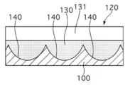
- membrane irrespective of electrodeposition is shown typically.
- the cross section of the skirt part outer peripheral surface of Embodiment 2 is shown typically.
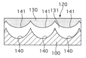
- membrane irrespective of electrodeposition is shown typically.
- the cross section of the skirt part outer peripheral surface of Embodiment 3 is shown typically.
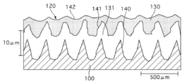
- the cross section of the outer peripheral surface of the skirt part in the experimental result of Embodiment 3 is shown.
- the cross section of the skirt part outer peripheral surface of Embodiment 4 is shown typically.
- the cross section of the skirt part outer peripheral surface of Embodiment 5 is shown typically.
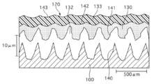
- the cross section of the outer peripheral surface of the skirt part in the experimental result of Embodiment 5 is shown.
- the cross section of the skirt part outer peripheral surface of Embodiment 6 is shown typically.
- the cross section of the outer peripheral surface of the skirt part in the experimental result of Embodiment 6 is shown.
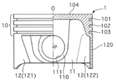
- FIG. 1 is a view of a piston 1 of an internal combustion engine (hereinafter referred to as an engine) according to the present embodiment as viewed from a direction in which an axis P of a piston pin hole 111 extends.
- the right half shows a cross section of the piston 1 in a plane including the axis O of the piston 1.
- the engine is, for example, a 4-cycle gasoline engine, but is not limited thereto.
- the piston 1 is accommodated in a cylinder 2 of the engine so as to be able to reciprocate.
- FIG. 1 is a view of a piston 1 of an internal combustion engine (hereinafter referred to as an engine) according to the present embodiment as viewed from a direction in which an axis P of a piston pin hole 111 extends.
- the right half shows a cross section of the piston 1 in a plane including the axis O of the piston 1.
- the engine is, for example, a 4-cycle gasoline engine, but is not limited thereto.
- the piston 1 is accommodate
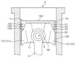
- the cylinder 2 shows a cross section in which the piston 1 and the cylinder 2 connected to the connecting rod (connecting rod) 4 are cut by a plane including the axis O and perpendicular to the axis P.
- the cylinder 2 is formed in a cylinder block, and its inner wall (inner wall surface) 20 is substantially cylindrical. That is, the inner wall 20 of the cylinder 2 (hereinafter referred to as the cylinder inner wall 20) is substantially circular in a plane orthogonal to the axis of the cylinder 2.
- a cylinder head is installed in the cylinder block. The cylinder head closes the opening of the cylinder 2.
- a combustion chamber is defined between the crown surface 104 of the piston 1, the cylinder inner wall 20, and the cylinder head.
- the piston 1 is connected to one end side (small end portion 40) of the connecting rod 4 via the piston pin 3.
- the other end side (large end portion) of the connecting rod 4 is connected to the crankshaft.
- the piston 1 is formed by casting or the like using an aluminum alloy (for example, Al-Si AC8A) as a base material (base material).
- the piston 1 has a bottomed cylindrical shape and includes a head portion 10, an apron portion 11, and a skirt portion 12.
- the head portion 10 has a crown surface 104 at the crown portion.
- the inner peripheral side of the part excluding the crown part in the head part 10 is hollow.
- Three ring grooves 101, 102, and 103 extend in the circumferential direction of the piston 1 (around the axis O) on the outer peripheral surface of the head portion 10.
- Compression rings 51 and 52 are installed in the ring grooves 101 and 102 on the side close to the crown surface 104, and an oil ring 53 is installed in the ring groove 103 on the side far from the crown surface 104.
- the apron portion 11 and the skirt portion 12 are on the opposite side of the crown surface 104 with respect to the ring grooves 101 to 103 in the direction (axial direction) in which the axis O of the piston 1 extends.
- the inner peripheral side of the skirt portion 12 and the apron portion 11 is hollow.
- Each apron section 11 has a pin boss 110.
- Each pin boss 110 has a piston pin hole 111.
- the piston pin hole 111 extends through the pin boss 110 in the radial direction of the piston 1.
- the end of the piston pin 3 is fitted into the piston pin hole 111.
- the outer peripheral surface of the apron portion 11 is closer to the axis O than the outer peripheral surface of the head portion 10 (skirt portion 12).
- a pair of skirt portions 12 is provided on both sides in the radial direction of the piston 1 with the axis O interposed therebetween.
- the skirt portion 12 includes a thrust side skirt portion 121 and an anti-thrust side skirt portion 122.
- the skirt portion 12 is sandwiched between both apron portions 11 in the circumferential direction of the piston 1.
- the skirt portion 12 is thinner than the apron portion 11.
- the outer peripheral surface of the skirt portion 12 (hereinafter referred to as the skirt portion outer peripheral surface) 120 has an arc shape. Twice the distance from the axis O to the outer peripheral surface 120 of the skirt (the outer diameter of the skirt 12) is slightly larger than the outer diameter of the head 10 and slightly smaller than the diameter of the cylinder inner wall 20 (inner diameter of the cylinder 2). Small.
- FIG. 3 shows a cross section (part) on the outer peripheral side of the skirt portion 12 in a plane including the axis O.
- the outer peripheral surface 120 of the skirt part is covered with at least one layer of the film part 13.
- the film part 13 is only one layer of the electrodeposition film 130.
- the base material 100 of the piston 1 is covered with one layer of electrodeposited film 130, and this electrodeposited film 130 is exposed on the outer peripheral surface 120 of the skirt portion (in other words, the electrodeposited film 130 is a cylinder). Directly opposite the inner wall 20. The meaning of exposure is the same below).
- the piston 1 has a streak 14 on the outer peripheral surface 120 of the skirt portion.
- the striations 14 are streak-like grooves extending in the circumferential direction of the piston 1, and a plurality of the striations 14 are arranged adjacent to each other in the axial direction of the piston 1.
- the streak 14 includes a streak 140 in the base material 100 of the piston 1.
- the streak 140 is formed in a spiral shape around the axis O by, for example, turning with a cutting tool or rolling with a roller.
- the cross-sectional shape (shape in a plane including the axis O) of the streak 140 is U-shaped or V-shaped following the shape of the cutting edge of the processing tool. Note that the cross-sectional shape of the striations 140 may be stepped, for example, by partially overlapping the processing.
- the shape of the portion between the adjacent streaks 140 may be a protrusion (pointed) or a flat shape (flat tip).
- the distance between the adjacent stripes 140 is a predetermined value (for example, about 250 ⁇ m) in the range from several tens ⁇ m to several hundreds ⁇ m.
- the height and depth of the streak 140 are predetermined values (for example, around 10 ⁇ m) in a range from several ⁇ m to several tens of ⁇ m.
- the height (depth) of the streak 14 refers to the distance from the lowest part to the highest part (top) of the streak 14 in the normal direction of the skirt outer peripheral surface 120 (the radial direction of the piston 1). .
- the direction in which the striations 140 extend along the outer peripheral surface 120 of the skirt portion only needs to have an angle with respect to the axial direction of the piston 1, and the striations 140 are oblique to the circumferential direction of the piston 1, for example. May extend.
- the striations 140 may meander in a wave shape instead of a straight line shape.
- the shape and size of the streak 140 may be changed depending on the position and range of the skirt portion 12.
- the electrodeposition film 130 is a film formed by electrodeposition coating. That is, the electrodeposition film 130 is formed by electrodeposition of the electrodeposition paint on the outer peripheral surface 120 of the skirt portion.
- the electrodeposition film 130 functions as a decorative layer for improving the smoothness of the outer peripheral surface 120 of the skirt portion.
- the electrodeposition film 130 includes a resin (binder resin) as a binder (binder) having adhesiveness to other materials.
- a resin excellent in heat resistance and wear resistance for example, a polyamideimide resin (hereinafter referred to as PAI) is used.
- the electrodeposition film 130 includes at least one of other binder resins such as a polyimide resin (hereinafter referred to as PI) or an epoxy resin (hereinafter referred to as EP) as a binder resin, together with or instead of PAI. May be included.
- PI like PAI, is excellent in heat resistance and wear resistance.
- PAI, PI, and EP are excellent in adhesion.
- the electrodeposition film 130 may contain additives other than the binder resin.
- the electrodeposition film 130 does not contain a conductive solid lubricant such as graphite or molybdenum disulfide.
- the film part 13 (in this embodiment, the electrodeposition film 130) is formed so as to cover the outer peripheral surface 120 of the skirt part.
- the surface treatment method of the piston 1 includes an electrodeposition film forming step. In the electrodeposition film forming step, the electrodeposition coating step, the water washing step, the firing step, and the cooling step are performed in this order. In addition, before the electrodeposition coating process, in order to improve the adhesion of the film part 13, for example, oil or dirt is removed from the outer peripheral surface 120 of the skirt part of the piston 1 (base material 100) to be coated. May be performed.
- the skirt portion 12 of the piston 1 that is an object to be coated is exposed as an electrode in an aqueous electrodeposition paint, and the electrodeposition paint side is used as a counter electrode.
- the electrodeposition paint side is used as a counter electrode.
- the skirt portion 12 is used as an anode
- the electrodeposition paint side is used as a cathode.
- the polarity may be reversed using a cationic paint.
- a base binder resin is dissolved or dispersed in water (in a colloidal state). Add organic solvents, neutralizers, additives, etc. as necessary.
- Electrodeposition can be performed by a constant current method or a constant voltage method.
- a DC voltage is applied between the electrodes to pass a DC current.
- the electrodeposition conditions are, for example, a voltage of several tens of V to several tens of V and a processing time (energization time) of several seconds to several tens of seconds.
- an electric current is passed, the water in the electrodeposition paint is electrolyzed and the paint particles containing the binder resin are ionic, and the paint particles are electrophoresed on the side of the skirt portion 12 as an electrode.
- the paint particles deposited on the outer peripheral surface 120 of the skirt part are fused by Joule heat generated from electric resistance, and lose ionicity and become insoluble.
- an electrically insulating film (showing non-conductive resistance) (electrodeposition film 130) covering the base material 100 is formed on the outer peripheral surface 120 of the skirt portion.
- the thickness (film thickness) of the electrodeposition film 130 can be appropriately adjusted depending on the electrodeposition conditions.
- FIG. 4 schematically shows a first example of an apparatus 5 for performing an electrodeposition coating process.
- the apparatus 5 includes an electrodeposition paint storage means 6, an electrodeposition paint distribution means 7, an energization means 8, and a control means 9.
- the electrodeposition paint storage means 6 has a liquid tank 60.
- the liquid tank 60 stores the electrodeposition paint.
- the electrodeposition paint distribution means 7 includes a masking plate 71, a nozzle 72, a pipe line 73, and a pump 74.
- a pair of masking plates 71 are arranged on both sides in the radial direction of the piston 1.
- One masking plate 711 covers a region excluding the thrust side skirt portion 121 on the outer peripheral surface on one side in the radial direction of the piston 1.
- the other masking plate 712 covers a region excluding the anti-thrust side skirt portion 122 on the outer peripheral surface on the other radial side of the piston 1.
- a sealing material (O-ring) 713 is disposed between the masking plate 71 and the outer peripheral surface of the piston 1 so as to surround the skirt portion 12.
- a pair of nozzles 72 are arranged on both sides in the radial direction of the piston 1.
- One nozzle 721 faces the thrust side skirt portion 121 and the other nozzle 722 faces the anti-thrust side skirt portion 122.
- the nozzles 721 and 722 are connected to the pump 74 via pipe lines 731 and 732, respectively.
- the pump 74 is connected to the liquid tank 60 through a pipe line 730. The pump 74 sucks the electrodeposition paint from the liquid tank 60 and discharges it to the nozzle 72 side.
- the energizing means 8 has electrodes, electrodeposition wires 83 and 84, and a power source 85.
- the electrode has an anode 81 and a cathode 82.
- the anode 81 is disposed on the piston 1 side.
- the anode 81 has a rod shape, and the tip thereof faces the crown surface 104 of the piston 1.
- the cathode 82 has a cylindrical shape and is arranged on the inner peripheral side (electrodeposition paint side) of each nozzle 72.
- the inner peripheral side of the cathode 82 is in contact with the electrodeposition paint.
- the outer peripheral side of the cathode 82 is covered with an insulating material 720 (see FIG. 5).
- the anode 81 is connected to the power source 85 through the electrodeposition wiring 83.
- the cathode 82 is connected to the power source 85 through the electrodeposition wiring 84.
- the control means 9 includes a control panel 90, actuators, and control wirings 92 to 94.
- the actuator includes an anode driving actuator 91, a masking plate driving actuator 92, and a pump driving actuator.
- the anode driving actuator 91 can press and separate the anode 81 from the crown surface 104 of the piston 1.
- the masking plate driving actuator 92 can press or separate the masking plate 71 from the outer peripheral surface of the piston 1.
- the pump driving actuator drives the pump 74.
- Each actuator is connected to the control panel 90 via control wires 92, 93 and 94, respectively.
- the power source 85 is connected to the control panel 90 via the control wiring 95.
- the positions of the masking plate 71 and the anode 81, the operation state of the pump 74, and the energization state of the electrodes 81 and 82 are controlled by the control panel 90.
- FIG. 5 schematically shows the state of the electrodeposition coating process by the apparatus 5.
- the cross section of piston 1 grade in the plane containing axis O of piston 1 seen from the direction where axis P of piston pin hole 111 extends is shown.
- the periphery of each outer peripheral surface 120 of the skirt portions 121 and 122 is masked by masking plates 711 and 712, respectively.
- the electrodeposition paint discharged from the pump 74 is sprayed from the nozzles 721 and 722 toward the skirt portions 121 and 122, hits the skirt portion outer peripheral surface 120, and then falls by gravity and returns to the inside of the liquid tank 60.
- the binder resin in the electrodeposition paint is electrophoresed in the jet from the inner peripheral surface side of the cathode 82 disposed in the nozzle 72 toward the outer peripheral surface 120 of the skirt portion serving as the anode.
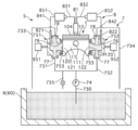
- FIG. 6 is a cross-sectional view schematically showing a second example of the device 5.
- the electrodeposition paint distribution means 7 has a liquid passage member 75 (751, 752).
- the actuator includes a liquid path member driving actuator 95 (951, 952).
- a pair of the liquid path member 75 and the liquid path member driving actuator 95 are arranged on both sides of the piston 1 in the radial direction.
- FIG. 7 is a perspective view schematically showing the liquid path member 75 and the liquid path member driving actuator 95.
- the liquid path member 75 is made of a conductive material, and has an opening 76 having substantially the same shape as the outer peripheral surface 120 of the skirt. The opening 76 faces the outer peripheral surface 120 of the skirt part.
- a seal member (O-ring) 753 is disposed between the periphery of the opening 76 in the liquid passage member 75 and the outer peripheral surface of the piston 1 so as to surround the outer peripheral surface 120 of the skirt portion.
- the liquid path member 75 constitutes a liquid path having the skirt portion outer peripheral surface 120 and the inner peripheral surface of the liquid path member 75 as a part thereof. That is, the liquid path member 75 has two openings 77 and 78 in addition to the opening 76. One of these two openings 77 is connected to the pump 74 via a pipe line 731 or 732, and the other opening 78 is connected to the liquid tank 60 via a pipe line 733 or 734.
- the liquid path that connects the pump 74 and the liquid tank 60 via the liquid path member 75 includes the inner peripheral surface of the liquid path member 75 and the outer peripheral surface 120 of the skirt part.
- a drain line 735 is connected to a line 731 connecting the pump 74 and the liquid line member 751.
- the pipe line 735 opens into the liquid tank 60.
- the cathode 82 is installed in the liquid path member 75.
- the liquid path member driving actuator 95 can press and separate the liquid path member 75 from the outer peripheral surface of the piston 1.
- the position of the liquid path member 75 is controlled by the control panel 90.
- Other configurations of the device 5 are the same as those in the first example.
- the pump 74 sucks the electrodeposition paint from the liquid tank 60 through the pipe line 730 and discharges it to the liquid path member 75 side.
- the electrodeposition paint discharged from the pump 74 returns to the liquid tank 60 through the liquid path in the liquid path member 75.
- the electrodeposition paint contacts the outer peripheral surface 120 of the skirt portion.
- the binder resin in the electrodeposition paint is electrophoresed from the inner peripheral surface side of the liquid path member 75 serving as the cathode toward the skirt outer peripheral surface 120 serving as the anode.
- the third example of the device 5 has a liquid tank, electrodes, electrodeposition wiring, and a power source.
- the anode is installed on the crown surface 104 of the piston 1, and the cathode is installed in the electrodeposition paint of the liquid tank.
- Each of these electrodes is connected to a power source via an electrodeposition wiring.
- the piston pin hole 111 of the piston 1 is plugged for masking.
- a portion (a skirt portion 12 and an apron portion 11) excluding the head portion 10 of the piston 1 is immersed in an electrodeposition coating material in a liquid tank to conduct electricity. From the viewpoint of efficiently forming the electrodeposition film 130 on the outer peripheral surface 120 of the skirt portion, the first example is most preferable, and the second example is next preferable. From the viewpoint of simplifying the device 5, the third example is preferable.
- the remaining liquid is washed away by washing the skirt portion 12 (electrodeposition film 130) after the electrodeposition coating step.
- finish and top coatability are improved.
- the water washing step may be omitted.
- the electrodeposition film 130 the solvent is volatilized and the resin is polymerized and cured.
- the electrodeposition film 130 is cured, and the electrodeposition film 130 adheres to the outer peripheral surface 120 of the skirt portion.
- the skirt portion 12 (electrodeposition film 130) after the water washing step is fired under predetermined firing conditions.
- the hardness and adhesion of the electrodeposited film 130 are improved compared to simple baking and drying (for example, 90 ° C. to 120 ° C. and no holding time).
- the firing conditions are, for example, 180 ° C. and 30 minutes. Since firing at a low temperature of 200 ° C. or lower is also possible, the firing process can be easily applied even when the base material 100 of the piston 1 is an aluminum alloy.
- the skirt portion 12 (electrodeposited film 130) after the firing step is cooled.
- natural cooling by leaving may be used instead of forced cooling.
- the rotational movement of the crankshaft is converted into the reciprocating movement of the piston 1.
- the outer peripheral surface 120 of the surface of the skirt portion 12 slides against the cylinder inner wall 20.
- the swinging motion of the piston 1 around the axis P of the piston pin 3 inside the cylinder 2 is suppressed, so that the reciprocating motion of the piston 1 is smoothed and the hitting sound is suppressed.
- sliding means that the outer peripheral surface 120 of the skirt part moves relative to the inner wall 20 while being in solid contact with the cylinder inner wall 20 without any oil film of engine oil, and It includes both of movement of the skirt outer peripheral surface 120 with respect to the cylinder inner wall 20 in a state where the skirt part outer surface 120 is interposed through the oil film with respect to the cylinder inner wall 20 (that is, not in contact with solids).
- the connecting rod 4 is inclined with respect to the axis of the cylinder 2 according to the crank angle. In the expansion stroke (combustion stroke) and compression stroke, pressure acts from the crown surface 104 side of the piston 1.
- a high surface pressure region having a relatively high surface pressure and a low surface pressure region having a relatively low surface pressure are generated on the outer peripheral surface 120 of the skirt portion.
- a part of the outer peripheral surface 120 of the skirt portion (hereinafter, this is referred to as a first range) becomes a high surface pressure region by having irregularities larger than the thickness of the oil film between the inner wall 20 and the cylinder.
- a range other than the first range (hereinafter referred to as the second range) of the outer peripheral surface 120 of the skirt has unevenness smaller than the thickness of the oil film between the cylinder inner wall 20 and the low surface pressure region. It becomes.
- the lubrication between them becomes boundary lubrication, and solid contact between them occurs more frequently. That is, depending on the situation, the friction coefficient increases between the cylinder inner wall 20 and the first range because the parameters according to the conditions such as load and speed in the Stribeck curve are located in the boundary lubrication region. Scuffing may occur.
- the second range slides against the cylinder inner wall 20 with an oil film formed between the second range and the cylinder inner wall 20.
- the thickness of the oil film becomes larger than the surface roughness of both (the lubrication gap becomes larger than the lower limit value), and the lubrication between them becomes fluid lubrication, so that no solid contact occurs between the two. That is, in many scenes, the above-mentioned parameter in the Stribeck curve is located in the fluid lubrication region between the cylinder inner wall 20 and the second range, so that the friction coefficient is reduced and scuffing may occur between the two. Less is.
- the electrodeposition film 130 In this embodiment, exposure of the base material 100 of the piston 1 to the outer peripheral surface 120 of the skirt portion including the first range is suppressed by the electrodeposition film 130. Since the base material 100 and the cylinder inner wall 20 are prevented from coming into contact with each other in the first range on the skirt outer peripheral surface 120, the scuff resistance of the piston 1 is improved. Since PAI and PI are excellent in wear resistance and heat resistance, peeling of the electrodeposited film 130 from the substrate 100 is suppressed. Therefore, when the electrodeposition film 130 contains PAI or PI as the binder resin, the above effect is improved.
- the electrodeposition film 130 contains a binder resin but does not contain a solid lubricant (a layer of resin alone).
- the adhesive force of the electrodeposition film 130 is high, and the adhesion between the electrodeposition film 130 and the substrate 100 is good. Further, the electrodeposition film 130 is cured by being baked. Thereby, peeling of the electrodeposition film 130 from the substrate 100 is suppressed.
- the electrodeposition film 130 may contain a solid lubricant that is an electrical insulator, for example, a fluororesin (polytetrafluoroethylene; hereinafter referred to as PTFE).
- PTFE fluororesin
- the electrodeposition film 130 is in the uppermost layer and is exposed on the outer peripheral surface 120 of the skirt portion. For this reason, the frictional force reducing action (lubricity) can be obtained at an earlier stage after the engine operation is started.
- the wearability and adhesion of the electrodeposition film 130 can be adjusted.
- the case where the solid lubricant content is 50 wt% (hereinafter referred to as wt%) or more and 95 wt% or less and the binder resin content is 5 wt% or more and 50 wt% or less is described.
- the electrodeposition film 130 is easily worn when the solid lubricant content is 50 wt% or more (the binder resin content is 50 wt% or less). Therefore, the initial familiarity when the skirt outer peripheral surface 120 slides on the cylinder inner wall 20 is improved.
- the binder resin content is 5 wt% or more (the solid lubricant content is 95 wt% or less), the adhesive strength of the electrodeposition film 130 is secured to some extent. Therefore, a decrease in adhesion between the electrodeposition film 130 and the substrate 100 is suppressed.
- the electrodeposition film 130 when the solid lubricant content is greater than 0 wt% and 50 wt% or less, and the binder resin content is 50 wt% or more and less than 100 wt%, the electrodeposition film 130 is a binder.
- the adhesive strength is high because the resin content is 50 wt% or more (the solid lubricant content is 50 wt% or less). Therefore, the adhesion between the electrodeposition film 130 and the substrate 100 is good.
- oil engine oil
- the oil is retained in the striations even when the engine is stopped.
- the retained oil is appropriately supplied between the outer peripheral surface of the skirt portion and the cylinder inner wall. For example, when the engine is started from a stopped state or when the piston reciprocates at high speed, it is possible to prevent the oil from running out.
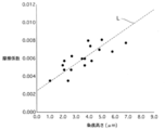
- the present inventors have found the following. That is, the friction coefficient under fluid lubrication between the outer peripheral surface 120 of the skirt portion and the cylinder inner wall 20 (hereinafter referred to as fluid lubrication friction coefficient) is closely related to the height of the streak 14 on the outer peripheral surface 120 of the skirt portion. As the streak 14 becomes lower (the outer peripheral surface 120 of the skirt portion becomes closer to smoothness), the fluid lubrication friction coefficient becomes smaller.
- the height of the streak 14 on the outer peripheral surface 120 of the skirt described above refers to the height of the streak 140 processed into the base material 100 when the base material 100 of the piston 1 is not covered with the coating part 13.
- the height of the groove (striking line 14) in the coating part 13 formed (as a result) in a portion corresponding to the stripe 140 processed into the substrate 100. It points to.
- the amount of lubricating oil supplied and other conditions were adjusted to achieve fluid lubrication.
- the friction coefficient (fluid lubrication friction coefficient) at the time of sliding was measured by changing the height of the streak a plurality of times.
- Fig. 8 shows the coefficient of friction for each height of the streak when the test conditions are surface pressure: 2.8 MPa, speed: 2.0 m / sec, and the amount of lubricating oil (grade 5W-30) supplied: 40 ml / min.
- the measurement results are shown.
- a plurality of data indicating the measurement results (a plurality of points in the graph) were within an area within a predetermined range centered on one straight line L.
- the straight line L is such that the friction coefficient changes in proportion to the height of the streak.
- This experimental result shows that the fluid lubrication friction coefficient is smaller when the streak 14 on the outer peripheral surface 120 of the skirt portion is low than when it is high.
- the smoothness of the outer peripheral surface 120 of the skirt is improved by the electrodeposition film 130. That is, in the electrodeposition film forming step, the bottom of the striation 140 is filled with the electrodeposition film 130, so that the striation 14 is lowered as shown schematically in FIG. 3 (the striation shape is smoothed). . After being covered with the electrodeposition film 130, the smoothness of the outer peripheral surface 120 of the skirt is improved as compared with that before being covered with the electrodeposition film 130. By improving the smoothness, the friction coefficient (fluid lubrication friction coefficient) when the skirt portion outer peripheral surface 120 comes into contact with oil and fluid lubrication is performed becomes small. Therefore, engine efficiency (fuel consumption) is improved.
- friction between the outer peripheral surface 120 of the skirt portion and the cylinder inner wall 20 (and energy loss due to this friction) is mainly constituted by friction under boundary lubrication and friction under fluid lubrication.
- the ratio of the latter friction to the whole is overwhelmingly larger than the ratio of the former friction to the whole regardless of the operating conditions and the stroke of the piston 1. Since the latter friction (friction under fluid lubrication) is reduced by the electrodeposition film 130, the overall friction (and energy loss) generated on the outer peripheral surface 120 of the skirt portion is effectively reduced.
- the film thickness of the electrodeposition film 130 can be appropriately selected within the range in which the above smoothing effect can be obtained.
- the lowering of the streak 14 by the electrodeposition film 130 means the following. That is, on the surface of the coating portion 13 covering the base material 100 of the piston 1, a new streak 141 (result) is provided at a site corresponding to the streak 140 processed on the base material 100 (covering the streak 140). As) formed.
- the height of the streak 141 is lower in the electrodeposition film 130 than in the general film portion 13 (not depending on electrodeposition). This will be specifically described with reference to the drawings.
- FIG. 9 schematically shows a cross section of the outer peripheral side of the skirt portion 12 as in FIG. 3. Let the height of the streak 140 be a0.
- the height of the stripes 141 formed on the film part 13 that directly covers the substrate 100 is defined as a1.
- a paint is composed of a volatile component such as a solvent and a solid component such as a resin.
- the solid component remains as a film after the paint is dried (volatile components are volatilized). Volatile components volatilize from the paint and do not remain as a film.
- the surface of the film part 13 before the volatile components of the paint are volatilized is completely free from irregularities regardless of whether or not it is a part corresponding to the streak 140, as shown by a one-dot chain line in FIG. Is a smooth surface.
- the distance from the lowest part of the streak 140 to the surface of the film part 13 before volatilization is (a0 + x).
- b1 (a0 + x) ⁇ (Equation 2)
- c1 ⁇ x (Equation 3)
- ⁇ 0.3 to 0.5 in the case of a normal paint, but 0.1 to 0.6 when a special one is included.
- equation (4) is established.
- (1- ⁇ ) a0 is the height of the streak 141.
- the striations 141 of the coating portion 13 are lower than the original striations 140 by the volume ratio ⁇ of the solid component in the coating material of the coating portion 13.
- the fact that the streak 14 is lowered (the smoothness is improved) by the electrodeposition film 130 means that a1 is lower than (1- ⁇ ) a0, and therefore is expressed by the following formula (5).
- a1 ⁇ (1- ⁇ ) a0 (Equation 5) That is, the amount of the solid component in the electrodeposition coating is larger than the volume ratio ⁇ , and the striation 141 of the electrodeposition film 130 is lower than the original striation 140.
- the striations 14 of the coating portion 13 are lower than the original striations 14 by the volume ratio ⁇ of the solid component in the coating material of the coating portion 13. Therefore, if a plurality of normal films other than the electrodeposition film 130 are stacked, the outer peripheral surface 120 of the skirt portion can be smoothed to the same extent as the electrodeposition film 130. In the present embodiment, by using the electrodeposition film 130, the streak 14 becomes lower than the volume ratio ⁇ as in the above formula (5).
- the skirt portion outer peripheral surface 120 can be efficiently smoothed by the electrodeposition film 130 alone without stacking many layers. Therefore, the manufacturing process of the piston 1 can be simplified.
- the skirt portion 12 is not limited to a single layer, and may include a plurality of layers of electrodeposition films 130.
- the skirt portion 12 of this embodiment has only one layer of electrodeposition film 130. Since many layers of the electrodeposition film 130 are not stacked, the manufacturing process of the piston 1 can be simplified.
- the mechanism of smoothing the skirt portion outer peripheral surface 120 by the electrodeposition film 130 can be considered as follows, for example.
- the paint deposited on the outer peripheral surface 120 of the skirt during energization loses conductivity. That is, the electrical resistance increases and no current flows. Therefore, the growth of the film should stop and a thin film having a uniform thickness should be formed on the outer peripheral surface 120 of the skirt portion.
- the heat release state of Joule heat differs between the bottom (valley) and the top (mountain) of the streak 14. This is considered to contribute to smoothing. That is, heat dissipation is good at the top of the streak 14, but heat is trapped at the bottom.
- the film is made porous by the gas generated by electrolysis, so that the electric resistance of the film does not increase so much and current continues to flow. Therefore, the film continues to grow, and the bottom of the streak 14 has a higher film growth rate. Thereby, the uniformity of the film thickness is inhibited, and a film is formed so as to fill the bottom of the streak 14.
- membrane of a porous state turns into a continuous film
- the piston 1 does not necessarily have the striations 140. That is, the electrodeposition film 130 may be provided on the piston 1 that does not have the striation 140 on the base material 100 on the outer peripheral surface 120 of the skirt portion.
- the base material 100 has the striations 140 on the skirt outer peripheral surface 120. Thereby, the surface area of the base material 100 on the outer peripheral surface 120 of the skirt portion is increased, the contact area between the base material 100 and the electrodeposition film 130 is increased, and the adhesive force between the two is improved. Therefore, since peeling of the electrodeposition film 130 from the base material 100 is suppressed, solid contact between the base material 100 and the cylinder 2 in the first range is more reliably suppressed.
- the striations 140 formed on the base material 100 will be exposed on the outer peripheral surface 120 of the skirt, and the lubrication function by the striations 140 will be exhibited.
- the film formed on the outer peripheral surface 120 of the skirt portion by energization becomes conductive. Since this film has a small electric resistance, the generation of Joule heat is reduced. Therefore, the growth rate of the film due to the fusion of the paint particles is not so different between the bottom and the top of the streak 14. Thereby, the uniformization of the film thickness is promoted, and the film is less likely to be formed so as to fill the bottom of the streak 14 (smoothing is hindered).
- the conductive solid component includes a conductive solid lubricant, for example, graphite (hereinafter referred to as C) and molybdenum disulfide (hereinafter referred to as MoS 2 ).
- C graphite
- MoS 2 molybdenum disulfide
- the electrodeposition paint of this embodiment does not contain a conductive solid lubricant. Therefore, since the electrodeposition paint is closer to non-conductivity, the smoothing action by the electrodeposition film 130 is improved. It should be noted that a small amount of conductive solid component (solid lubricant) is added to or mixed in the electrodeposition paint as long as the non-conductivity of the electrodeposition paint is maintained to some extent and the above-described smoothing action by the electrodeposition film 130 is obtained. It is permissible.
- a solid lubricant such as PTFE that is an electrical insulator is allowed to be included in the electrodeposition paint. That is, even when a non-conductive solid lubricant is added to the electrodeposition paint, the electrodeposition paint when energized exhibits the same behavior as when no solid lubricant is added and fills the bottom of the streak 14. Then, the electrodeposition film 130 is formed. Note that the solid lubricant contained in the electrodeposition film 130 is not limited to PTFE as long as it is more nonconductive than C and MoS 2 .
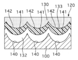
- FIG. 10 shows a cross section of the outer peripheral side of the skirt portion 12 in a plane including the axis O of the piston 1 in the present embodiment.
- the film part 13 has an electrodeposition film 130 and a film of one layer separately from the electrodeposition film 130. That is, the skirt portion 12 of the piston 1 has two layers of films.
- the film other than the electrodeposition film 130 is a lubricating film 131.
- the film part 13 has an electrodeposition film 130 and a lubricating film 131 in this order from the base material 100 side of the piston 1.
- the electrodeposition film 130 covers the substrate 100.
- the composition of the electrodeposition film 130 is the same as in the first embodiment.
- the lubricating film 131 covers the electrodeposition film 130 and is exposed on the outer peripheral surface 120 of the skirt portion.
- the lubricating film 131 includes a solid lubricant and a binder resin.
- the solid lubricant is C.
- the lubricant film 131 may contain at least one of other solid lubricants such as MoS 2 or PTFE as a solid lubricant, together with or in place of C.
- the binder resin has a function of fixing a solid lubricant to an object to be coated, and for example, PAI is used.
- the lubricating film 131 may contain at least one of other binder resins, for example, PI or EP, as a binder resin, together with or instead of PAI.
- the lubricating film 131 has a solid lubricant content of 50 wt% or more and 95 wt% or less, and a binder resin content of 5 wt% or more and 50 wt% or less.
- the surface treatment method (main treatment) of the piston 1 includes an electrodeposition film forming step and a lubricating film forming step.
- the electrodeposition film forming step and the lubricating film forming step are performed in this order.
- the procedure of the electrodeposition film forming step is the same as that in the first embodiment.
- a so-called drying / baking method is performed in which a coating in which a solid lubricant is dispersed in a solution of a binder resin is applied to the surface of an object, and a dry film is formed by drying and baking.
- the painting process, the drying process, and the cooling process are performed in this order.
- the paint is applied to the outer peripheral surface 120 (electrodeposited film 130) of the skirt by screen printing.
- the coating may be performed by printing other than screen printing, spraying of a paint by spraying or the like, or dipping in the paint.
- a binder resin and a solid lubricant are blended in an organic solvent, and additives and hard particles are added to the solution as necessary, and then mixed and dispersed using a bead mill or the like. .
- the paint can be diluted with an organic solvent as required.
- a coating film that covers the electrodeposition film 130 is formed on the outer peripheral surface 120 of the skirt by the coating process.
- the coating film is baked and dried under drying conditions such as heating at 90 ° C. to 120 ° C. (no holding time is required). For example, when the paint is out of the hand, the drying process ends.
- the volatile component (organic solvent) is removed from the coating film by drying, and the solid lubricant is fixed on the outer peripheral surface 120 of the skirt portion through the binder resin by baking, so that the lubricating film 131 is formed.
- the skirt portion 12 (lubricating film 131) after the firing step is cooled. Note that natural cooling may be used instead of forced cooling.
- the drying process in the lubricating film forming process may be changed to a baking process, or the baking process in the electrodeposition film forming process may be changed to a drying process (similar to that in the lubricating film forming process).
- the electrodeposition film forming process includes a baking process
- the lubricating film forming process includes a drying process.
- the lubricating film 131 By the lubricating film 131, friction between the outer peripheral surface 120 of the skirt portion and the cylinder inner wall 20 is reduced relatively early (initially) after the engine operation is started. That is, in the first range, even if no oil film is formed between the skirt outer peripheral surface 120 and the cylinder inner wall 20, the lubricating film 131 is exposed on the skirt outer peripheral surface 120. The agent reduces the magnitude of the frictional force between them.
- the lubricating film 131 may have a solid lubricant content of 50 wt% or less (a binder resin content of 50 wt% or more).
- the adhesive force of the lubricating film 131 is high, and the adhesion between the lubricating film 131 and the electrodeposition film 130 is good.
- the lubricant film 131 has a solid lubricant content of 50 wt% or more (a binder resin content of 50 wt% or less).
- the lubricating film 131 is easy to wear because it contains a large amount of solid lubricant (less binder resin). Therefore, the initial familiarity when the outer peripheral surface of the piston 1 slides on the cylinder inner wall 20 is improved. That is, the first range (the surface of the lubricating film 131) is worn and smoothed quickly, and quickly adjusts to the cylinder inner wall 20.
- the lubrication gap becomes larger than the lower limit value.
- the improvement in smoothness reduces the fluid lubrication friction coefficient in the first range (and the second range as will be described later). Accordingly, the magnitude of the frictional force between the outer peripheral surface 120 of the skirt portion and the cylinder inner wall 20 is reduced, and the friction loss at the skirt portion 12 is reduced.
- the lubricant film 131 has a binder resin content of 5 wt% or more (a solid lubricant content of 95 wt% or less). Therefore, the adhesive force of the lubricating film 131 is secured to some extent, and a decrease in the adhesion between the lubricating film 131 and the electrodeposition film 130 is suppressed. Since the lubricating film 131 is not fired, it is more likely to be worn than when fired. Therefore, the initial familiarity by the lubricating film 131 is easily obtained. In order to improve the initial conformability, a binder resin having a low wear resistance may be used as the binder resin contained in the lubricating film 131.
- the striation shape in the base material 100 is smoothed by the electrodeposition film 130 in at least the second range of the outer peripheral surface 120 of the skirt (the striation 14 is lowered by the electrodeposition film 130).
- the lubricating film 131 so as to cover the smoothed skirt portion outer peripheral surface 120 (electrodeposited film 130)
- the surface of the lubricating film 131 is also smoothed (as a result). That is, the skirt outer peripheral surface 120 (at least in the second range) covered with the lubricating film 131 is smoothed. This reduces the fluid lubrication friction coefficient in the second range.
- a piston including a solid lubricant and a highly wearable coating on the outer peripheral surface of the skirt is known.
- the coating in the first range of the outer peripheral surface of the skirt portion, the coating is worn early and becomes familiar with the inner wall of the cylinder, so that the boundary lubrication is changed to the fluid lubrication and the fluid lubrication friction coefficient is reduced.
- the coating in the second range other than the first range, the coating does not move while being in direct contact with the inner wall of the cylinder, so that the fluid lubrication remains and the height of the streak formed on the coating in the second range is high. There is no change. Therefore, in the 2nd range which is a contact surface with oil, since smoothness is low, high friction is shown.
- the smoothness is improved by reducing the striations 14 by the electrodeposition film 130 in the second range which is a contact surface with oil. Therefore, the friction under fluid lubrication is reduced not only in the first range but also in the second range. That is, the friction coefficient (friction force) under fluid lubrication is reduced over the entire skirt portion outer peripheral surface 120 (including the first range and the second range).
- c2 be the distance from the highest part (top) of the streak 141 to the highest part (top) of the streak 142.
- equation (6) holds.
- a2 a1 + c2-b2 (Formula 6) It is assumed that the surface of the lubricating film 131 after the coating process of the lubricating film 131 and before the volatile component of the paint is volatilized is a smooth surface without unevenness as shown by a two-dot chain line in FIG.
- the distance from the highest part (top) of the streak 141 to the surface of the lubricant film 131 before volatilization is defined as y.
- the distance from the lowest part of the streak 141 to the surface of the lubricant film 131 before volatilization is (a1 + y).
- ⁇ be the ratio of the volume of the solid component to the volume of the entire coating of the lubricating coating 131.
- the solid component is a solid lubricant or resin.
- Equation 8) y Note that ⁇ is 0.3 to 0.5 for ordinary paints, but 0.1 to 0.6 when special materials are included. From the above equations (6) to (8), the following equation (9) is established.
- Equation 9 (1- ⁇ ) a1 is the height of the streak 142 formed on the surface of the lubricating film 131 by the volatilization of the volatile components from the paint of the lubricating film 131, based on a1.
- equation (4) the above equation (9) can be rewritten as the following equation (10).
- a2 (1- ⁇ ) (1- ⁇ ) a0 (Equation 10) That is, the striation 142 in the multilayer of the coatings 130 and 131 is lower than the original striation 140 by the volume ratio ⁇ and ⁇ of the solid component in each coating material of the coatings 130 and 131.
- the height of the streak 142 is reduced by the electrodeposition film 130 (improves smoothness) means that a2 is lower than (1- ⁇ ) (1- ⁇ ) a0. 11).
- This equation (11) is also derived from the above equations (5) and (9).
- the volume ratio (1- ⁇ ) of the volatile component to the height a1 of the stripe 141 in the electrodeposition film 130 is A streak 142 in the lubricating coating 131 is formed at the hung height a2.
- the stripe 142 of the lubricant film 131 is lower than the original stripe 141 by the volume ratio ⁇ of the solid component in the paint of the lubricant film 131.
- the electrodeposition film 130 contains a binder resin but does not contain a solid lubricant. Therefore, the adhesive force of the electrodeposition film 130 is high, and the adhesion between the electrodeposition film 130 and the substrate 100 is good. Further, the adhesion between the electrodeposition film 130 and the lubricating film 131 is good. Further, the electrodeposition film 130 is cured by being baked. Therefore, peeling of the electrodeposition film 130 from the substrate 100 is suppressed.
- the electrodeposition film 130 may include a solid lubricant that is an electrical insulator.
- a smoothing action by the electrodeposition film 130 can be obtained, and when the electrodeposition film 130 is exposed on the outer peripheral surface 120 of the skirt due to wear of the lubricant film 131 or the like, electrodeposition including a solid lubricant is performed. Lubricity due to the film 130 can be obtained.
- FIG. 12 shows a cross section of the outer peripheral side of the skirt portion 12 in a plane including the axis O of the piston 1 in the present embodiment.
- the skirt portion 12 has a two-layered film.
- the film has a lubricating film 131 and an electrodeposition film 130 in this order from the substrate 100 side.
- the lubricating film 131 covers the substrate 100.
- the lubricating film 131 contains C as a solid lubricant.
- the solid lubricant may contain MoS 2 together with C or instead of C.
- the lubricating coating 131 has a solid lubricant content of greater than 0 wt% and no greater than 50 wt%, and a binder resin content of no less than 50 wt% and less than 100 wt%.
- the electrodeposition film 130 covers the lubricating film 131 and is exposed on the outer peripheral surface 120 of the skirt portion.
- the composition of the electrodeposition film 130 is the same as in the first embodiment.
- the lubricating film forming step and the electrodeposition film forming step are performed in this order.
- the painting step, the firing step, and the cooling step are performed in this order.
- the skirt portion 12 (lubricant film 131) after the painting step is fired under firing conditions such as, for example, 180 ° C. for 30 minutes or 200 ° C. for 20 minutes.
- firing conditions such as, for example, 180 ° C. for 30 minutes or 200 ° C. for 20 minutes.
- an electrodeposition coating step In the electrodeposition film forming step, an electrodeposition coating step, a water washing step, a drying step, and a cooling step are performed in this order.
- the coating film In the drying step, the coating film is baked and dried under drying conditions such as heating at 90 ° C. to 120 ° C. (no holding time is required). For example, when the paint is out of the hand, the drying process ends.
- Other steps in the electrodeposition film forming step are the same as those in the first embodiment. Note that the water washing step may be omitted.
- the electrodeposition film 130 and the lubricating film 131 prevent the base material 100 from being exposed on the outer peripheral surface 120 of the skirt portion. Therefore, like the first embodiment, the scuff resistance of the piston 1 is improved.
- the smoothness of the outer peripheral surface 120 of the skirt is improved by the electrodeposition film 130.
- the electrodeposition film 130 does not contain a solid lubricant. Therefore, the adhesive force of the electrodeposition film 130 is high, and the adhesion between the electrodeposition film 130 and the lubricating film 131 is good.
- the electrodeposition film 130 may include a solid lubricant that is an electrical insulator. In this case, a smoothing action by the electrodeposition film 130 is obtained, and lubricity and the like by the electrodeposition film 130 are obtained.
- the electrodeposition film 130 since the electrodeposition film 130 does not contain a solid lubricant, the electrodeposition film 130 has higher wear resistance than the case where a solid lubricant is contained. On the other hand, since the electrodeposition film 130 is not fired, it is more likely to be worn than when fired. Therefore, in the first range, the electrodeposition film 130 is worn and smoothed quickly, and is easily adapted to the cylinder inner wall 20 quickly. Further, the lubricating film 131 covered with the electrodeposition film 130 is easily exposed to the outer peripheral surface 120 of the skirt portion. Thereby, the merit (lubricity and initial familiarity) of the lubricating film 131 is easily obtained.
- a binder resin having a low wear resistance may be used as the binder resin contained in the electrodeposition film 130.
- the electrodeposition film 130 includes a solid lubricant that is an electrical insulator, the content of the solid lubricant may be increased (in other words, the content of the binder resin may be decreased).
- the lubricating coating 131 contains a solid lubricant (the content of the solid lubricant is greater than 0 wt%). Therefore, if the lubricating film 131 is exposed on the outer peripheral surface 120 of the skirt portion due to wear of the electrodeposited film 130 in the first range, the outer peripheral surface 120 of the skirt portion and the inner wall 20 of the cylinder by the solid lubricant as in the second embodiment. The magnitude of the frictional force between the two is reduced.
- the lubricating film 131 may have a solid lubricant content of 50 wt% or more. In this case, the lubricating film 131 is easily worn.
- the lubricant film 131 has a binder resin content of 50 wt% or more (a solid lubricant content of 50 wt% or less). Therefore, the adhesive force of the lubricating film 131 is high, and the adhesion between the lubricating film 131 and the substrate 100 is good. Further, the adhesion between the lubricating film 131 and the electrodeposition film 130 is good.
- the lubricating film 131 is cured by being baked. Therefore, peeling of the lubricating film 131 from the base material 100 is suppressed.
- the base material 100 has the striations 140 on the outer peripheral surface 120 of the skirt portion. As a result, the lubricating film 131 is more firmly bonded to the base material 100.
- the solid lubricant contained in the lubricating film 131 is C or MoS 2 and has conductivity. Therefore, in the electrodeposition coating process, the outer peripheral surface 120 of the skirt covered with the lubricant film 131 easily functions as an electrode, and it is easy to form the electrodeposition film 130 on the lubricant film 131.
- FIG. 13 shows a cross section on the outer peripheral side of the skirt portion 12 in a plane including the axis O of the piston 1 in an experimental result when the electrodeposition condition in the electrodeposition coating process is 60 V for 5 seconds.
- Table 1 shows the thickness of each film formed in this experiment and the height of the streak 14.
- the film thickness refers to the highest part of the striation 14 in the film of the next layer covering the film from the highest part (top) of the striation 14 in the film of a certain layer in the normal direction of the outer peripheral surface 120 of the skirt part. The distance to (top).
- the reference position for measuring the film thickness is not limited to the top of the streak 14.
- Each numerical value of the film thickness and the height of the streak 14 represents an average of a plurality of streaks 14.
- the height a0 of the streak 140 processed on the substrate 100 was 9.5 ⁇ m.
- the film thickness of the lubricating film 131 was 6.9 ⁇ m.
- the height a1 of the streak 141 formed on the lubricating film 131 was 6.5 ⁇ m.
- the film thickness of the electrodeposition film 130 was 2.0 ⁇ m.
- the height a2 of the streak 142 formed on the electrodeposition film 130 was 1.7 ⁇ m.
- the height of the streak 14 is reduced from a1 to a2 as compared with the case where the outer peripheral surface 120 (base material 100) of the skirt is covered only with the lubricating film 131 (hereinafter referred to as Comparative Example 2). It can be seen that the fluid lubrication friction coefficient decreases to approximately 4/9. According to the graph of FIG. 8, the fluid lubrication friction coefficient is approximately 0.0045 or less when the height of the streak 14 on the skirt outer peripheral surface 120 is 2.0 ⁇ m or less. At this time, it can be seen that the fluid lubrication friction coefficient decreases to approximately 3/8 or less compared to Comparative Example 1, and decreases to approximately half or less compared to Comparative Example 2.
- Table 2 shows the experimental results showing the height a2 of the streak 142 when the electrodeposition conditions are changed.
- the heights a0 and a1 of the striations 140 and 141 and the film thickness of the lubricating film 131 were the same as the above experimental results when the electrodeposition conditions were 60 V and 5 seconds.
- Table 2 When the processing time (energization time) was 5 seconds, a2 was 5.0 ⁇ m when the voltage was 40 V, and 1.7 ⁇ m when the voltage was 60 V.
- the processing time was 10 seconds, the voltage was 6.3 ⁇ m when the voltage was 40 V, 1.6 ⁇ m when the voltage was 60 V, and 1.5 ⁇ m when the voltage was 80 V and 100 V.
- a2 is 1.1 ⁇ m when the voltage is 40 V and 1.0 ⁇ m when 60 V, when the processing time is 15 seconds. Under the same conditions, a2 was 1.3 ⁇ m when the voltage was 40V and 0.9 ⁇ m when the voltage was 60V, when the processing time was 30 seconds. When the voltage was 40 V, a2 did not significantly decrease from the height of the streak 141 when the treatment time was 10 seconds or less. When the voltage was 60 V, even when the processing time was 10 seconds or less, the height was significantly reduced from the height of the streak 141, and became 2.0 ⁇ m or less.
- a lubricating film 131 is interposed between the base material 100 and the electrodeposition film 130. Electrodeposition is performed by causing an electric current to flow through the lubricating film 131 and depositing an electrodeposition paint on the surface of the lubricating film 131.
- the lubricating film 131 had lower conductivity than the base material 100 and covered the base material 100 with a film thickness of 6.9 ⁇ m. Even in this case, it was found that the electrodeposition film 130 having a height a2 of the streak 142 as low as 2.0 ⁇ m or less was formed as described above under the electrodeposition condition of 60 V for 5 seconds.
- the film thickness of the electrodeposition film 130 was 2.0 ⁇ m. This value is significantly smaller than the film thickness (6.9 ⁇ m) of the lubricating film 131. As described above, since the increase in the thickness of the electrodeposition film 130 is suppressed, the electrodeposition film 130 is easily worn. Thereby, initial familiarity and lubricity improve as mentioned above. In order to improve the initial conformability and the like, the film thickness of the electrodeposition film 130 is not limited to 2.0 ⁇ m, and may be slightly thicker than, for example, about 3.0 ⁇ m, preferably 3 ⁇ m or less (greater than 0 ⁇ m). is there.
- FIG. 14 shows a cross section of the outer peripheral side of the skirt portion 12 in a plane including the axis O of the piston 1 in the present embodiment.
- the film part 13 includes an electrodeposition film 130 and a lower film (first film) 132 and an upper film (second film) 133 separately from the electrodeposition film 130. That is, the skirt portion 12 of the piston 1 has a three-layer coating.
- the lower layer film 132 and the upper layer film 133 are formed by multilayering a lubricant film containing a binder resin and a solid lubricant.
- the film part 13 includes an electrodeposition film 130, a lower layer film 132, and an upper layer film 133 in this order from the substrate 100 side.
- the electrodeposition film 130 covers the substrate 100.
- the composition of the electrodeposition film 130 is the same as in the first embodiment.
- the lower layer film 132 is closer to the substrate 100 than the upper layer film 133, that is, on the lower layer side, and covers the electrodeposition film 130.
- the lower layer film 132 includes PAI as a binder resin.
- the binder resin may contain at least one of PI or EP together with PAI or instead of PAI.
- the lower layer film 132 contains C as a solid lubricant.
- the solid lubricant may contain at least one of MoS 2 or PTFE together with C or instead of C.
- the lower layer film 132 has a solid lubricant content of greater than 0 wt% and 50 wt% or less, and a binder resin content of 50 wt% or more and less than 100 wt%.
- the upper layer film 133 is on the side farther from the substrate 100 than the lower layer film 132, that is, on the upper layer side.
- the upper layer film 133 covers the lower layer film 132 and is exposed on the outer peripheral surface 120 of the skirt portion.
- the upper layer film 133 includes PAI as a binder resin.
- the binder resin may contain at least one of PI or EP together with PAI or instead of PAI.
- the upper film 133 includes MoS 2 as a solid lubricant.
- the solid lubricant may contain at least one of C or PTFE together with MoS 2 or instead of MoS 2 .
- the upper film 133 has a solid lubricant content of 50 wt% or more and 95 wt% or less, and a binder resin content of 5 wt% or more and 50 wt% or less.
- the surface treatment method (main treatment) of the piston 1 includes an electrodeposition film formation step, a lower layer film formation step, and an upper layer film formation step.
- the electrodeposition film forming step, the lower layer film forming step, and the upper layer film forming step are performed in this order.
- the procedure of the electrodeposition film forming step is the same as that in the first embodiment.
- the procedure of the lower layer film forming step and the upper layer film forming step is the same as the procedure of the lubricating film forming step of the second embodiment.
- the baking process in an electrodeposition film formation process may be changed into a drying process
- the drying process in a lower layer film formation process may be changed into a baking process
- the drying process in an upper film formation process is changed into a baking process. Also good.
- the electrodeposition film forming process includes a baking process
- the lower film forming process and the upper film forming process include a drying process.
- the film part 13 has a lower layer film 132 and an upper layer film 133 in this order.
- the upper layer film 133 provides the same operational effects (such as initial familiarity) as the lubricating film of the second embodiment.
- the lower layer film 132 includes a solid lubricant (the content of the solid lubricant is greater than 0 wt%). Therefore, in the first range, if the lower layer film 132 is exposed to the skirt portion outer peripheral surface 120 due to wear of the upper layer film 133 or the like, the skirt portion outer peripheral surface 120 and the cylinder are formed by the solid lubricant of the lower layer film 132 as in the second embodiment. The magnitude of the frictional force with the inner wall 20 is reduced.
- the lower layer film 132 has a binder resin content of 50 wt% or more (a solid lubricant content of 50 wt% or less). Therefore, the adhesion of the lower layer film 132 is high, and the adhesion between the lower layer film 132 and the electrodeposition film 130 is good. Further, the adhesion between the lower layer film 132 and the upper layer film 133 is good.
- the electrodeposition film 130 provides the same effects (improved smoothness, etc.) as the electrodeposition film 130 of the second embodiment. That is, the outer peripheral surface 120 of the skirt covered with the lubricating film (upper layer film 133) is smoothed.
- the meaning of the height of the streak 14 on the outer peripheral surface 120 of the skirt covered with the three-layer coating being lowered by the electrodeposition film 130 (improving smoothness) is understood according to the first and second embodiments. be able to.
- the ratio of the volume of the solid component to the volume of the entire coating in the lower layer film 132 is ⁇
- the ratio of the volume of the solid component to the volume of the entire coating in the upper layer 133 is ⁇ .
- the electrodeposition film 130 may include a solid lubricant that is an electrical insulator.
- FIG. 15 shows a cross section of the outer peripheral side of the skirt portion 12 in a plane including the axis O of the piston 1 in the present embodiment.
- the skirt portion 12 has a three-layer coating.
- the film part 13 has a lower layer film 132, an electrodeposition film 130, and an upper layer film 133 in this order from the substrate 100 side.
- the lower layer film 132 covers the substrate 100.
- the composition of the lower layer film 132 is the same as that of the lubricating film 131 of the third embodiment.
- the electrodeposition film 130 covers the lower layer film 132.
- the composition of the electrodeposition film 130 is the same as in the first embodiment.
- the upper film 133 covers the electrodeposition film 130 and is exposed on the outer peripheral surface 120 of the skirt portion.
- the composition of the upper film 133 is the same as in the fourth embodiment.
- the lower layer film forming step, the electrodeposition film forming step, and the upper layer film forming step are performed in this order.
- the procedure of the lower layer film forming process is the same as the procedure of the lubricating film forming process of the third embodiment.
- the procedure of the electrodeposition film forming step is the same as that in the third embodiment.
- the procedure of the upper layer film forming step is the same as that in the fourth embodiment.
- the upper layer film 133 provides the same operational effects (such as initial familiarity) as the lubricating film 131 of the second embodiment.
- the electrodeposition film 130 smoothes the skirt outer peripheral surface 120 (at least the second range) covered with the lubricating film (upper film 133), as with the electrodeposition film 130 of the second embodiment.
- the electrodeposition film 130 does not contain a solid lubricant. Therefore, the adhesive force of the electrodeposition film 130 is high, and the adhesion between the electrodeposition film 130 and the lower layer film 132 is good. Further, the adhesion between the electrodeposition film 130 and the upper film 133 is good.
- the electrodeposition film 130 may include a solid lubricant that is an electrical insulator.
- the electrodeposition film 130 Since the electrodeposition film 130 is not baked, like the electrodeposition film 130 of the third embodiment, the electrodeposition film 130 wears and smoothes quickly (with the upper layer film 133) in the first range, and quickly becomes familiar with the cylinder inner wall 20. Cheap. Further, since the lower layer film 132 covered with the electrodeposition film 130 is easily exposed to the skirt portion outer peripheral surface 120, the merit (lubricity and initial familiarity) of the lower layer film 132 is easily obtained.
- the electrodeposition film 130 may include a binder resin having low wear resistance, or may include a large amount of a solid lubricant that is an electrical insulator. The lower layer film 132 provides the same effects as the lubricating film 131 of the third embodiment.
- FIG. 16 shows the same cross section as FIG. 13 in the experimental results when the electrodeposition condition is 60 V for 5 seconds.
- Table 3 shows the film thickness and the height of the streak 14 of each film formed in this experiment.
- the heights a0, a1, a2 of the striations 140, 141, 142, and the film thicknesses of the lower layer film 132 and the electrodeposition film 130 were the same as the experimental results (FIG. 13, Table 1) in the third embodiment.
- Table 3 The film thickness of the upper film 133 was 4.0 ⁇ m.
- the height a3 of the streak 143 formed on the upper film 133 was 1.2 ⁇ m.
- the film thickness of the electrodeposition film 130 was 3 ⁇ m or less. As described above, since the increase in the thickness of the electrodeposition film 130 is suppressed, the electrodeposition film 130 is easily worn. Thereby, initial familiarity and lubricity improve as mentioned above. In order to improve initial conformability and the like, the film thickness of the electrodeposition film 130 may be slightly thicker than, for example, approximately 3.0 ⁇ m.
- FIG. 17 shows a cross section of the outer peripheral side of the skirt portion 12 in a plane including the axis O of the piston 1 in the present embodiment.
- the skirt portion 12 has a three-layer coating.
- the film part 13 has a lower layer film 132, an upper layer film 133, and an electrodeposition film 130 in this order from the substrate 100 side.
- the lower layer film 132 covers the substrate 100.
- the composition of the lower layer film 132 is the same as that of the lubricating film 131 of the third embodiment.
- the upper film 133 covers the lower film 132.
- the composition of the upper film 133 is the same as in the fourth embodiment.
- the upper film 133 includes MoS 2 as a solid lubricant.
- the solid lubricant may contain C together with MoS 2 or instead of MoS 2 , but does not contain PTFE.
- the electrodeposition film 130 covers the upper film 133 and is exposed on the outer peripheral surface 120 of the skirt portion.
- the composition of the electrodeposition film 130 is the same as in the first embodiment.
- the lower layer film formation step, the upper layer film formation step, and the electrodeposition film formation step are performed in this order.
- the procedures of the lower layer coating formation step and the upper layer coating formation step are the same as the procedure of the lubricating coating formation step of the third embodiment.
- the coating step in the upper layer film forming step is performed after the firing step in the lower layer film forming step.
- the procedure of the electrodeposition film forming step is the same as that in the third embodiment.
- the electrodeposition film 130 provides the same effects (smoothing of the outer peripheral surface 120, etc.) as the electrodeposition film 130 of the third embodiment.
- the first range if the upper layer film 133 is exposed on the outer peripheral surface 120 of the skirt due to wear of the electrodeposited film 130, the magnitude of the frictional force is reduced by the solid lubricant of the upper layer film 133, and the upper layer film 133 is also removed. Early wear improves the initial familiarity.
- the first range if the lower layer film 132 is exposed on the outer peripheral surface 120 of the skirt due to wear of the electrodeposition film 130 and the upper layer film 133, the magnitude of the frictional force is reduced by the solid lubricant of the lower layer film 132.
- the lower layer film 132 has a binder resin content of 50 wt% or more (a solid lubricant content of 50 wt% or less). Therefore, the adhesive strength of the lower layer film 132 is high, and the adhesion between the lower layer film 132 and the substrate 100 is good. Further, the adhesion between the lower layer film 132 and the upper layer film 133 is good.
- the solid lubricant contained in the lower layer film 132 and the upper layer film 133 is C or MoS 2 and has conductivity. Therefore, in the electrodeposition coating process, it is easy to cause the outer peripheral surface 120 of the skirt covered with the lower layer film 132 and the upper layer film 133 to function as an electrode and form the electrodeposition film 130 on the upper layer film 133.
- FIG. 18 shows the same cross section as FIG. 13 in the experimental result when the electrodeposition condition is 100 V for 10 seconds.
- Table 4 shows the film thickness of each film formed in this experiment and the height of the streak 14. (Table 4) The height a0 of the streak 140 was 8.8 ⁇ m.
- the film thickness of the lower layer film 132 was 6.0 ⁇ m.
- the height a1 of the streak 141 formed on the lower layer film 132 was 5.6 ⁇ m.
- the film thickness of the upper film 133 was 4.0 ⁇ m.
- the height a2 of the streak 142 formed on the upper film 133 was 5.2 ⁇ m.
- the film thickness of the electrodeposition film 130 was 3.2 ⁇ m.
- the height a3 of the stripe 143 formed on the electrodeposition film 130 was 1.9 ⁇ m.
- a1 5.6 ⁇ m
- a2 5.2 ⁇ m
- a1 (1- ⁇ ) (1- ⁇ ) a0
- the height of the streak 14 is lowered from a2 to a3, so that the fluid lubrication friction coefficient is reduced to about half. It turns out that it falls.
- Table 5 shows the experimental results showing the height a3 of the streak 143 when the electrodeposition conditions are changed.
- the heights a0 to a2 of the striations 140 to 142 and the film thicknesses of the lubricating coatings 132 and 133 were the same as the above experimental results when the electrodeposition condition was 10 seconds at 100V. (Table 5)
- a3 was 5.0 ⁇ m when the voltage was 60V, 4.4 ⁇ m when the voltage was 80V, 3.4 ⁇ m when the voltage was 100V, and 3.8 ⁇ m when the voltage was 120V.
- a3 can be lowered to 2.0 ⁇ m or less if it is 10 seconds at 100V.
- lubricating films lower film 132 and upper film 133 are interposed.
- the electrodeposition is performed by causing an electric current to flow through the lubricant films 132 and 133 and depositing an electrodeposition paint on the surface of the upper film 133.
- the formed electrodeposition film 130 had a thickness of 3.2 ⁇ m. This value is significantly smaller than the film thickness (10.0 ⁇ m) of the lubricating coatings 132 and 133. As described above, since the increase in the thickness of the electrodeposition film 130 is suppressed, the electrodeposition film 130 is easily worn. Thereby, initial familiarity and lubricity improve as mentioned above.
- the electrodeposition film 130 may include a binder resin having low wear resistance, or may include a large amount of a solid lubricant that is an electrical insulator.
- the concrete structure of this invention is not limited to embodiment, The design change of the range which does not deviate from the summary of invention are included in the present invention.
- the base material of the piston is not limited to an aluminum alloy but may be iron or the like.
- PAI, PI, and EP are excellent in adhesion, and can be applied regardless of the substrate.
- any combination or omission of each constituent element described in the claims and the specification is possible within a range where at least a part of the above-described problems can be solved or a range where at least a part of the effect is achieved. It is.
Landscapes
- Engineering & Computer Science (AREA)
- General Engineering & Computer Science (AREA)
- Chemical & Material Sciences (AREA)
- Combustion & Propulsion (AREA)
- Mechanical Engineering (AREA)
- Pistons, Piston Rings, And Cylinders (AREA)
Abstract
スカート部の外周面の流体潤滑摩擦係数を低減できる内燃機関のピストンを提供すること。 内燃機関のピストンは、シリンダの内壁に対して摺動するスカート部の外周面に少なくとも1層の電着膜を備える。
Description
本発明は、内燃機関のピストンまたはその表面処理方法に関する。
シリンダの内壁に対し摺動するスカート部の外周面に皮膜を有する内燃機関のピストンが知られている(例えば特許文献1)。
従来、スカート部の外周面の流体潤滑における摩擦係数について考慮されていなかった。
本発明の一実施形態のピストンは、好ましくは、スカート部の外周面に少なくとも1層の電着膜を備える。
よって、スカート部の外周面の流体潤滑摩擦係数を低減できる。
以下、本発明の一実施形態のピストンおよびその表面処理方法を実施するための形態を、図面に基づいて説明する。
[実施形態1]
まず、構成を説明する。図1は、本実施形態の内燃機関(以下、エンジンという。)のピストン1をピストンピン孔111の軸心Pが延びる方向から見た図である。右側半分で、ピストン1の軸心Oを含む平面内でのピストン1の断面を示す。エンジンは例えば4サイクル・ガソリンエンジンであるがこれに限られない。ピストン1は、エンジンのシリンダ2内に、往復移動可能に収容される。図2は、コネクティングロッド(コンロッド)4に連結されたピストン1とシリンダ2とを、軸心Oを含み軸心Pに対し直交する平面で切った断面を示す。シリンダ2は、シリンダブロックに形成され、その内壁(内側の壁面)20が略円筒状である。すなわち、シリンダ2の軸心に直交する平面内で、シリンダ2の内壁20(以下、シリンダ内壁20という。)は略円形である。シリンダブロックには、シリンダヘッドが設置される。シリンダヘッドはシリンダ2の開口を塞ぐ。ピストン1の冠面104とシリンダ内壁20とシリンダヘッドとの間に、燃焼室が区画される。ピストン1は、ピストンピン3を介してコンロッド4の一端側(小端部40)に連結される。コンロッド4の他端側(大端部)はクランクシャフトに連結される。
まず、構成を説明する。図1は、本実施形態の内燃機関(以下、エンジンという。)のピストン1をピストンピン孔111の軸心Pが延びる方向から見た図である。右側半分で、ピストン1の軸心Oを含む平面内でのピストン1の断面を示す。エンジンは例えば4サイクル・ガソリンエンジンであるがこれに限られない。ピストン1は、エンジンのシリンダ2内に、往復移動可能に収容される。図2は、コネクティングロッド(コンロッド)4に連結されたピストン1とシリンダ2とを、軸心Oを含み軸心Pに対し直交する平面で切った断面を示す。シリンダ2は、シリンダブロックに形成され、その内壁(内側の壁面)20が略円筒状である。すなわち、シリンダ2の軸心に直交する平面内で、シリンダ2の内壁20(以下、シリンダ内壁20という。)は略円形である。シリンダブロックには、シリンダヘッドが設置される。シリンダヘッドはシリンダ2の開口を塞ぐ。ピストン1の冠面104とシリンダ内壁20とシリンダヘッドとの間に、燃焼室が区画される。ピストン1は、ピストンピン3を介してコンロッド4の一端側(小端部40)に連結される。コンロッド4の他端側(大端部)はクランクシャフトに連結される。
ピストン1は、アルミニウム合金(例えばAl-Si系のAC8A)を母材(基材)として、鋳造等により成形される。ピストン1は、有底筒状であり、ヘッド部10とエプロン部11とスカート部12を有する。ヘッド部10は、その冠部に冠面104を有する。ヘッド部10において冠部を除く部位の内周側は中空である。ヘッド部10の外周面には、3本のリング溝101,102,103がピストン1の周方向(軸心Oの周り方向)に延びる。冠面104に近い側のリング溝101,102にはコンプレッションリング51,52がそれぞれ設置され、冠面104から遠い側のリング溝103にはオイルリング53が設置される。エプロン部11およびスカート部12は、ピストン1の軸心Oが延びる方向(軸心方向)において、リング溝101~103に対し冠面104とは反対側にある。スカート部12およびエプロン部11の内周側は中空である。エプロン部11は、軸心Oを挟んでピストン1の径方向両側に一対ある。各エプロン部11はピンボス110を有する。各ピンボス110はピストンピン孔111を有する。ピストンピン孔111は、ピンボス110を貫通してピストン1の径方向に延びる。ピストンピン孔111にはピストンピン3の端部が嵌合する。エプロン部11の外周面は、ヘッド部10(スカート部12)の外周面よりも軸心Oの側にある。スカート部12は、軸心Oを挟んでピストン1の径方向両側に一対ある。スカート部12は、スラスト側スカート部121と反スラスト側スカート部122を有する。スカート部12は、ピストン1の周方向で両エプロン部11に挟まれる。スカート部12は、エプロン部11よりも薄肉である。軸心Oに対し直交する平面内で、スカート部12の外周面(以下、スカート部外周面という。)120は円弧状である。軸心Oからスカート部外周面120までの距離の2倍(スカート部12の外径)は、ヘッド部10の外径よりも若干大きく、シリンダ内壁20の径(シリンダ2の内径)よりも僅かに小さい。
図3は、軸心Oを含む平面内でのスカート部12の外周側の断面(部分)を示す。スカート部外周面120は、少なくとも1層の皮膜部13で覆われる。本実施形態では、皮膜部13は電着膜130の1層のみである。スカート部外周面120において、ピストン1の基材100は1層の電着膜130で覆われ、この電着膜130はスカート部外周面120に露出する(言換えると、電着膜130はシリンダ内壁20に直接対向する。露出の意味について、以下同様。)。ピストン1は、スカート部外周面120に条痕14を有する。条痕14は、ピストン1の周方向に延びる筋状の溝であり、ピストン1の軸心方向で互いに隣接して複数並ぶ。条痕14は、ピストン1の基材100における条痕140を含む。条痕140は、例えばバイトによる旋削加工やローラによる転造加工によって、軸心Oの周りに螺旋状に形成される。条痕140の断面形状(軸心Oを含む平面内での形状)は、加工工具の刃先の形状に倣うU字状やV字状である。なお、条痕140の断面形状は、例えば加工が部分的に重複して行われることで、段差状であってもよい。隣接する条痕140の間の部位(以下、頂部という。)の形状は、(先が尖った)突起状でもよいし(先が平らな)平面状でもよい。隣接する条痕140の間の距離(条痕のピッチ)は、数十μmから数百μmまでの範囲における所定値(例えば略250μm前後)である。条痕140の高さないし深さは、数μmから数十μmまでの範囲における所定値(例えば10μm前後)である。ここで条痕14の高さ(深さ)とは、スカート部外周面120の法線方向(ピストン1の径方向)における当該条痕14の最低部から最高部(頂部)までの距離をいう。なお、スカート部外周面120に沿って条痕140が延びる方向は、ピストン1の軸心方向に対して角度を有していればよく、条痕140は例えばピストン1の周方向に対して斜めに延びてもよい。条痕140は、直線状でなく波状に蛇行してもよい。スカート部12の位置や範囲によって条痕140の形状や大きさを変えてもよい。
電着膜130は、電着塗装により形成される皮膜である。すなわち、電着膜130は、スカート部外周面120に対する電着塗料の電着により形成される。電着膜130は、スカート部外周面120の平滑性を向上させるための化粧層として機能する。電着膜130は、他材料との接着性を有する結合剤(バインダー)としての樹脂(バインダー樹脂)を含む。バインダー樹脂として、耐熱性および耐摩耗性に優れた樹脂、例えばポリアミドイミド樹脂(以下、PAIという。)が用いられる。なお、電着膜130は、バインダー樹脂として、PAIと共に、またはPAIに代えて、他のバインダー樹脂、例えばポリイミド樹脂(以下、PIという。)またはエポキシ樹脂(以下、EPという。)の少なくとも一方を含んでもよい。PIは、PAIと同様、耐熱性および耐摩耗性に優れる。PAI,PI,EPは、接着性にも優れる。また、電着膜130は、バインダー樹脂以外の添加物を含んでもよい。電着膜130は、グラファイトや二硫化モリブデン等の導電性を有する固体潤滑剤を含まない。
ピストン1の表面処理では、スカート部外周面120を覆うように皮膜部13(本実施形態では電着膜130)が形成される。ピストン1の表面処理方法は、電着膜形成工程を有する。電着膜形成工程では、電着塗装工程、水洗工程、焼成工程、冷却工程をこの順に行う。なお、電着塗装工程の前に、皮膜部13の密着性を向上する等のため、塗装対象であるピストン1(基材100)のスカート部外周面120から油分や汚れを除去する等の処理を行ってもよい。電着塗装工程では、水性の電着塗料中に、被塗物であるピストン1のスカート部12を電極として晒し、電着塗料の側を対極とする。例えばアニオン型塗料を用いる場合、スカート部12を陽極とし、電着塗料の側を陰極とする。なお、カチオン型塗料を用いて極性を逆にしてもよい。電着塗料を調製するには、例えば、基剤となるバインダー樹脂を水に溶かしまたは分散させる(コロイド状態とする)。必要に応じて有機溶剤や中和剤、添加剤等を加える。電着は、定電流法または定電圧法で行うことができる。所定の電着条件で、電極間に直流電圧を印加して直流電流を通じる。電着条件は、例えば、電圧が数十V~百数十Vで処理時間(通電時間)が数秒~数十秒である。電流を通じると、電着塗料中の水が電気分解してバインダー樹脂を含む塗料粒子がイオン性をもち、この塗料粒子が電極としてのスカート部12の側に電気泳動する。スカート部外周面120に析出した塗料粒子は電気抵抗から発生するジュール熱によって融着し、イオン性を失って不溶性となる。これにより、スカート部外周面120に、基材100を覆う電気絶縁性の(非導電性の抵抗を示す)皮膜(電着膜130)が形成される。電着膜130の厚さ(膜厚)は電着条件によって適宜調整可能である。
図4は、電着塗装工程を行うための装置5の第1の例を概略的に示す。装置5は、電着塗料貯留手段6と、電着塗料流通手段7と、通電手段8と、制御手段9とを有する。電着塗料貯留手段6は液槽60を有する。液槽60は電着塗料を貯留する。電着塗料流通手段7は、マスキング板71と、ノズル72と、管路73と、ポンプ74とを有する。マスキング板71は、ピストン1の径方向両側に一対配置される。一方のマスキング板711は、ピストン1の径方向一方側の外周面においてスラスト側スカート部121を除く領域を覆う。他方のマスキング板712は、ピストン1の径方向他方側の外周面において反スラスト側スカート部122を除く領域を覆う。マスキング板71とピストン1の外周面との間には、スカート部12を囲むようにシール材(Oリング)713が配置される。ノズル72は、ピストン1の径方向両側に一対配置される。一方のノズル721はスラスト側スカート部121に対向し、他方のノズル722は反スラスト側スカート部122に対向する。各ノズル721,722はそれぞれ管路731,732を介してポンプ74に接続される。ポンプ74は管路730を介して液槽60に接続される。ポンプ74は液槽60から電着塗料を吸入し、ノズル72の側へ吐出する。
通電手段8は、電極と、電着用配線83,84と、電源85を有する。電極は陽極81と陰極82を有する。陽極81はピストン1の側に配置される。陽極81はロッド状であり、その先端がピストン1の冠面104に対向する。陰極82は円筒状であり、各ノズル72の内周側(電着塗料の側)に配置される。陰極82の内周側は電着塗料に接する。陰極82の外周側は絶縁材720により覆われる(図5参照)。陽極81は電着用配線83を介して電源85に接続される。陰極82は電着用配線84を介して電源85に接続される。制御手段9は、制御盤90と、アクチュエータと、制御用配線92~94を有する。アクチュエータは、陽極駆動用アクチュエータ91と、マスキング板駆動用アクチュエータ92と、ポンプ駆動用アクチュエータを有する。陽極駆動用アクチュエータ91は、陽極81をピストン1の冠面104に対して押付けたり離間させたりすることが可能である。マスキング板駆動用アクチュエータ92は、マスキング板71をピストン1の外周面に対して押付けたり離間させたりすることが可能である。ポンプ駆動用アクチュエータは、ポンプ74を駆動する。各アクチュエータはそれぞれ制御用配線92,93,94を介して制御盤90に接続される。電源85は制御用配線95を介して制御盤90に接続される。マスキング板71および陽極81の位置、ポンプ74の作動状態、ならびに電極81,82への通電状態は、制御盤90により制御される。図5は、装置5による電着塗装工程の様子を模式的に示す。ピストンピン孔111の軸心Pが延びる方向から見た、ピストン1の軸心Oを含む平面内でのピストン1等の断面を示す。スカート部121,122の各外周面120の周囲はそれぞれマスキング板711,712によりマスキングされる。ポンプ74から吐出された電着塗料は、各ノズル721,722からスカート部121,122に向けてそれぞれ噴射され、スカート部外周面120に当たった後、重力により落下して液槽60の内部に戻る。電着塗料中のバインダー樹脂は、ノズル72に配置された陰極82の内周面の側から、陽極となるスカート部外周面120に向けて、噴流中を電気泳動する。
図6は、装置5の第2の例を概略的に示す断面図である。電着塗料流通手段7は、液路部材75(751,752)を有する。アクチュエータは、液路部材駆動用アクチュエータ95(951,952)を有する。液路部材75および液路部材駆動用アクチュエータ95は、ピストン1の径方向両側に一対配置される。図7は、液路部材75と液路部材駆動用アクチュエータ95を概略的に示す斜視図である。液路部材75は、導電性の材料で形成されており、スカート部外周面120と略同形状の開口部76を有する。開口部76はスカート部外周面120に対向する。液路部材75における開口部76の周囲とピストン1の外周面との間には、スカート部外周面120を囲むようにシール材(Oリング)753が配置される。液路部材75は、スカート部外周面120と液路部材75の内周面とをその一部とする液路を構成する。すなわち、液路部材75は、開口部76とは別に2つの開口部77,78を有する。これら2つのうち一方の開口部77は管路731または732を介してポンプ74に接続し、他方の開口部78は管路733または734を介して液槽60に接続する。液路部材75を介してポンプ74と液槽60とを接続する液路は、液路部材75の内周面とスカート部外周面120とをその一部とする。ポンプ74と液路部材751を接続する管路731には、ドレン用の管路735が接続する。管路735は液槽60に開口する。管路735にはドレンバルブがある。陰極82は液路部材75に設置される。液路部材駆動用アクチュエータ95は、液路部材75をピストン1の外周面に対して押付けたり離間させたりすることが可能である。液路部材75の位置は、制御盤90により制御される。装置5の他の構成は上記第1の例と同様である。ポンプ74は液槽60から管路730を介して電着塗料を吸入し、液路部材75の側へ吐出する。ポンプ74から吐出された電着塗料は、液路部材75における液路を通って、液槽60へ戻る。液路部材75における液路を通る際、電着塗料はスカート部外周面120に接する。電着塗料中のバインダー樹脂は、陰極となる液路部材75の内周面の側から、陽極となるスカート部外周面120に向けて、電気泳動する。
装置5の第3の例は、液槽と、電極と、電着用配線と、電源を有する。陽極はピストン1の冠面104に設置され、陰極は液槽の電着塗料中に設置される。これらの電極はそれぞれ電着用配線を介して電源に接続される。ピストン1のピストンピン孔111にマスキング用の栓をする。このピストン1のヘッド部10を除く部分(スカート部12およびエプロン部11)を液槽の電着塗料中に浸漬して、通電を行う。スカート部外周面120に電着膜130を効率よく形成するという観点からは、第1の例が最も好ましく、第2の例が次に望ましい。装置5の簡素化という観点からは、第3の例が好ましい。
水洗工程では、電着塗装工程後のスカート部12(電着膜130)を水洗することで、残存液を洗い流す。これにより、仕上り性や上塗適性が向上する。なお、水洗工程を省略してもよい。その後、加熱による乾燥(焼付け乾燥)を行うと、電着膜130において、溶剤が揮発すると共に樹脂が重合して硬化する。電着膜130が硬化すると共に、スカート部外周面120に対して電着膜130が密着する。焼成工程では、水洗工程後のスカート部12(電着膜130)を、所定の焼成条件で焼成する。焼成することで、単なる焼付け乾燥(例えば90℃~120℃で保持時間無し)よりも、電着膜130の硬度と密着性が向上する。焼成条件は、例えば180℃で30分である。200℃以下での低温焼成も可能であるため、ピストン1の基材100がアルミニウム合金である場合も焼成工程を容易に適用可能である。冷却工程では、焼成工程後のスカート部12(電着膜130)を冷却する。なお、強制的な冷却でなく自然的な(放置による)冷却でもよい。
次に、作用効果を説明する。クランクシャフトの回転運動はピストン1の往復運動に変換される。シリンダ2の内部をピストン1が往復運動する際、スカート部12の表面のうち外周面120はシリンダ内壁20に対し摺動する。これにより、シリンダ2の内部におけるピストンピン3の軸心Pを中心とするピストン1の首振り動作が抑制されるため、ピストン1の往復運動が円滑化されると共に打音が抑制される。なお、本明細書で摺動とは、スカート部外周面120が(部分的にでも)エンジンオイルの油膜を介さずシリンダ内壁20に固体同士で接触しながらこの内壁20に対し動くこと、および、スカート部外周面120がシリンダ内壁20に対して油膜を介した(すなわち固体同士で接触しない)状態でシリンダ内壁20に対し動くこと、の両方を含む。クランク角度に応じてコンロッド4はシリンダ2の軸心に対し傾く。膨張行程(燃焼行程)や圧縮行程では、ピストン1の冠面104の側から圧力が作用する。力の釣り合いにより、膨張行程でピストン1が下死点側へストロークする際、スラスト側スカート部121がシリンダ内壁20(スラスト側)に押付けられる。圧縮行程でピストン1が上死点側へストロークする際、反スラスト側スカート部122がシリンダ内壁20(反スラスト側)に押付けられる。シリンダ内壁20に押付けられる力(シリンダ内壁20との摺動面における面圧)は、燃焼圧力を受けてシリンダ内壁20に圧接するスラスト側スカート部121の方が、反スラスト側スカート部122よりも大きい。
スカート部外周面120において、シリンダ内壁20に押付けられる力(面圧ないし荷重)の分布を均一化することは、一般に困難である。通常、スカート部外周面120において、面圧が相対的に高い高面圧領域と相対的に低い低面圧領域とが生じる。スカート部外周面120のうち一部の範囲(以下、これを第1範囲という。)は、シリンダ内壁20との間の油膜の厚さより大きな凹凸を有することで、高面圧領域となる。一方、スカート部外周面120のうち第1範囲以外の範囲(以下、これを第2範囲という。)は、シリンダ内壁20との間の油膜の厚さより小さな凹凸を有することで、低面圧領域となる。
スカート部外周面120のうち第1範囲とシリンダ内壁20との間における油膜の形成は阻害されやすい一方、第2範囲とシリンダ内壁20との間には油膜が形成されやすい。エンジンの運転開始後、第1範囲が(部分的にでも)油膜を介さずシリンダ内壁20に固体同士で接触しつつ摺動する場面がある。例えば、ピストン1の上死点付近では、ピストン1の速度が低下すると共に荷重が増大する等により、シリンダ内壁20と第1範囲との間に油膜が特に形成されにくい。油膜の厚さが両者の表面粗さ以下となる(潤滑ギャップが下限値以下になる)と、両者間の潤滑は境界潤滑となり、両者間で固体接触がより頻繁に起こる。すなわち、場面によっては、シリンダ内壁20と第1範囲との間で、ストライベック曲線における荷重や速度等の条件によるパラメータが境界潤滑領域に位置することで、摩擦係数が大きくなると共に、両者間でスカッフが発生するおそれがある。一方、エンジン運転中、多くの場面で、第2範囲はシリンダ内壁20との間に油膜が形成された状態でシリンダ内壁20に対し摺動する。すなわち、油膜の厚さが両者の表面粗さよりも大きくなり(潤滑ギャップが下限値よりも大きくなり)、両者間の潤滑が流体潤滑となることで、両者間で固体接触が起こらない。すなわち、多くの場面では、シリンダ内壁20と第2範囲との間で、ストライベック曲線における上記パラメータが流体潤滑領域に位置することで、摩擦係数が小さくなると共に、両者間でスカッフが発生するおそれが少ない。
本実施形態で、第1範囲を含むスカート部外周面120にピストン1の基材100が露出することは、電着膜130によって抑制される。スカート部外周面120における第1範囲で、基材100とシリンダ内壁20とが固体同士で接触することが抑制されるため、ピストン1の耐スカッフ性が向上する。PAIやPIは耐摩耗性および耐熱性に優れるため、基材100からの電着膜130の剥離が抑制される。よって、電着膜130がバインダー樹脂としてPAIやPIを含む場合、上記効果が向上する。電着膜130は、バインダー樹脂を含む一方で、固体潤滑剤を含まない(樹脂単独の層である)。よって、電着膜130の接着力が高く、電着膜130と基材100との密着性がよい。また、電着膜130は、焼成されることで硬化する。これにより、基材100からの電着膜130の剥離が抑制される。
なお、電着膜130(電着塗料)は、電気的絶縁体である固体潤滑剤、例えばフッ素樹脂(ポリテトラフルオロエチレン。以下、PTFEという。)を含んでもよい。この場合、第1範囲で電着膜130がシリンダ内壁20に接触するときも、上記固体潤滑剤により、スカート部外周面120とシリンダ内壁20との間の摩擦力の大きさが低減される。本実施形態では、電着膜130が最上層にあり、スカート部外周面120に露出する。このため、エンジン運転開始後のより早期の段階で上記摩擦力低減作用(潤滑性)が得られる。この場合、電着膜130における固体潤滑剤およびバインダー樹脂の含有量を調整することで、電着膜130の摩耗性や密着性を調節することができる。例えば、電着膜130において、固体潤滑剤の含有量が50重量%(以下、wt%)以上かつ95wt%以下であり、バインダー樹脂の含有量が5wt%以上かつ50wt%以下である場合について説明する。電着膜130は、固体潤滑剤の含有量が50wt%以上(バインダー樹脂の含有量が50wt%以下)であることで、摩耗しやすい。よって、スカート部外周面120がシリンダ内壁20に対し摺動する際の初期馴染み性が向上する。また、バインダー樹脂の含有量が5wt%以上(固体潤滑剤の含有量が95wt%以下)であることで、電着膜130の接着力がある程度確保される。よって、電着膜130と基材100との密着性の低下が抑制される。一方、電着膜130において、固体潤滑剤の含有量が0wt%より大きくかつ50wt%以下であり、バインダー樹脂の含有量が50wt%以上かつ100wt%未満である場合、電着膜130は、バインダー樹脂の含有量が50wt%以上(固体潤滑剤の含有量が50wt%以下)であることで、接着力が高い。よって、電着膜130と基材100との密着性がよい。
一般に、スカート部外周面において、スカッフの発生を抑制する等のため、条痕を形成してこれに潤滑機能を発揮させることが行われる。すなわち、条痕にはエンジンオイル(以下、オイルという。)が溜まり、エンジンの停止中も条痕にオイルが保持される。保持されたオイルは、スカート部外周面とシリンダ内壁との間に適宜供給される。例えばエンジンが停止状態から始動する際や、ピストンが高速で往復移動する際、オイル切れが生じることが抑制される。これにより、スカート部外周面とシリンダ内壁との間でのスカッフ発生の抑制や、両者間の摩擦力低減によるピストンの往復運動の円滑化が図られる。これに対し、本発明者によって以下のことが見出された。すなわち、スカート部外周面120とシリンダ内壁20との間の流体潤滑下における摩擦係数(以下、流体潤滑摩擦係数という。)は、スカート部外周面120における条痕14の高さと密接な関係があり、条痕14が低くなる(スカート部外周面120が平滑に近づく)ほど流体潤滑摩擦係数が小さくなる。条痕14が低いほどスカート部外周面120とシリンダ内壁20との間の油膜のせん断抵抗が小さくなり、これが流体潤滑摩擦係数の低下に寄与している、と考えられる。なお、上記のスカート部外周面120における条痕14の高さとは、ピストン1の基材100を皮膜部13が覆わない場合には、基材100に加工された条痕140の高さを指し、基材100を皮膜部13が覆う場合には、基材100に加工された条痕140に相当する部位に(結果として)形成される、当該皮膜部13における溝(条痕14)の高さを指す。
スカート部外周面120における条痕14の高さと、流体潤滑摩擦係数との関係を調べるため、実験を行った。この実験では、チップ(ブロック)オンディスク式の摩擦摩耗試験機を用いた。スカート部12を模擬する試験片(AC8A製)の条痕が形成された表面を、シリンダ内壁20を模擬するディスク(FC250製)の表面(表面粗さ:平均0.5μmRa(min.0.42~max.0.66))に当てた。所定の荷重(面圧)および潤滑油を加えた状態で、ディスクを所定の速度で回転させた。ディスクの表面が試験片の表面に対して摺動する方向は、条痕が延びる方向に対し略直交する方向である。流体潤滑の状態となるよう、潤滑油の供給量その他の条件を調節した。条痕の高さを複数回変えて、摺動時の摩擦係数(流体潤滑摩擦係数)を測定した。図8は、試験条件を面圧:2.8Mpa、速度:2.0m/sec、潤滑油(グレード5W-30)の供給量:40ml/minとしたときの、条痕の各高さに対する摩擦係数の測定結果を示す。測定結果を示す複数のデータ(グラフにおける複数の点)は、1つの直線Lを中心とする所定範囲内の領域に収まった。上記直線Lは、条痕の高さに対し上記摩擦係数が比例して変化するものである。この実験結果は、スカート部外周面120における条痕14が低いときは高いときよりも流体潤滑摩擦係数が小さくなることを示す。
電着膜130により、スカート部外周面120の平滑性が向上する。すなわち、電着膜形成工程において、条痕140の底部が電着膜130で埋められることで、図3で模式的に示されるように条痕14が低くなる(条痕形状が平滑化する)。電着膜130で覆われた後、スカート部外周面120は、電着膜130で覆われる前よりも、平滑性が向上する。平滑性が向上することで、スカート部外周面120がオイルと接触して流体潤滑が行われる際の摩擦係数(流体潤滑摩擦係数)が小さくなる。よって、エンジンの効率(燃費)が向上する。エンジンの運転中、スカート部外周面120とシリンダ内壁20との間の摩擦(およびこの摩擦によるエネルギー損失)は、主に、境界潤滑下における摩擦と、流体潤滑下における摩擦とにより構成される。そして、運転条件やピストン1の行程に関わらず、後者の摩擦が全体に占める割合は、前者の摩擦が全体に占める割合よりも、圧倒的に多い。後者の摩擦(流体潤滑下における摩擦)が電着膜130により低減されることで、スカート部外周面120で生じる全体としての摩擦(およびエネルギー損失)が効果的に低減される。なお、電着膜130の膜厚は、上記平滑化作用が得られる範囲内で、適宜選択可能である。
ここで、電着膜130により条痕14が低くなる(平滑性が向上する)とは、次のことを意味する。すなわち、ピストン1の基材100を覆う皮膜部13の表面には、基材100に加工された条痕140に相当する(当該条痕140を覆う)部位に、新たな条痕141が(結果として)形成される。条痕141の高さは、(電着によらない)一般の皮膜部13よりも電着膜130のほうが低くなる。具体的に図を用いて説明する。図9は、図3と同様、スカート部12の外周側の断面を模式的に示す。条痕140の高さをa0とする。基材100を直接覆う皮膜部13に形成される条痕141の高さをa1とする。条痕140の最低部から条痕141の最低部までの距離をb1とする。条痕140の最高部(頂部)から条痕141の最高部(頂部)までの距離をc1とする。次式(1)が成り立つ。
a1=a0+c1-b1 (数1)
一般に塗料は、溶剤等の揮発成分と、樹脂等の固体成分からなる。固体成分は、塗料の乾燥(揮発成分の揮発)後も皮膜として残る。揮発成分は、塗料から揮発して、皮膜として残らない。塗装工程後、塗料の揮発成分が揮発する前の皮膜部13の表面は、図9の一点鎖線で示すように、条痕140に相当する部位であるか否かに関わらず、凹凸がなく完全に平滑な面であると仮定する。条痕140の最高部(頂部)から上記揮発前の皮膜部13の表面までの距離をxとする。条痕140の最低部から上記揮発前の皮膜部13の表面までの距離は(a0+x)となる。塗料全体の体積(揮発成分の体積と固体成分の体積との和)に対する固体成分の体積の比をαとすると、次式(2)(3)が成り立つ。
b1=(a0+x)α (数2)
c1=αx (数3)
なお、αは、通常の塗料であれば0.3~0.5であるが、特殊なものを含めると0.1~0.6である。上記式(1)~(3)より、次式(4)が成り立つ。
a1=a0+αx-α(a0+x)= (1-α)a0 (数4)
すなわち、塗料の揮発成分が揮発する前の状態で、条痕140に相当する部位で塗膜が平らであったとしても、この塗膜から揮発成分が揮発することで、皮膜部13の表面に条痕141が形成される。(1-α)a0は、この条痕141の高さである。皮膜部13の塗料における固体成分の体積比αの分だけ、当該皮膜部13の条痕141が元の条痕140よりも低くなる。電着膜130により条痕14が低くなる(平滑性が向上する)とは、a1が(1-α)a0よりも低くなることを意味するから、次式(5)で表される。
a1<(1-α)a0 (数5)
すなわち、電着塗料における固体成分の体積比αの分よりも多く、電着膜130の条痕141が元の条痕140よりも低くなる。
上記式(4)のように、皮膜部13の塗料からその揮発成分が揮発することにより、元の条痕14の高さに対し上記揮発成分の体積比(1-α)を掛けた高さで、当該皮膜部13の条痕14が形成される。言換えると、皮膜部13の塗料における固体成分の体積比αの分だけ、当該皮膜部13の条痕14が元の条痕14よりも低くなる。よって、電着膜130ではない通常の皮膜を何層も重ねれば、電着膜130によると同程度に、スカート部外周面120が平滑化されうる。本実施形態では、電着膜130を用いることにより、上記式(5)のように、体積比αの分よりも多く条痕14が低くなる。皮膜を何層も重ねることなく、電着膜130それ単独で、スカート部外周面120が効率的に平滑化される。よって、ピストン1の製造工程の簡略化が可能である。なお、スカート部12は1層に限らず複数層の電着膜130を有してもよい。本実施形態のスカート部12は電着膜130を1層のみ有する。電着膜130を何層も重ねることがないため、ピストン1の製造工程の簡略化が可能である。
なお、電着膜130によるスカート部外周面120の平滑化(条痕が低くなること)のメカニズムは、例えば以下のものが考えられる。電着塗装工程で、通電時にスカート部外周面120に析出した塗料は導電性を失う。すなわち、電気抵抗が上がって電流が流れなくなる。このため、皮膜の成長が止まって、スカート部外周面120には均一な厚さの薄膜が形成されるはずである。しかし、条痕14の底部(谷部)と頂部(山部)とではジュール熱の放熱状態が異なる。このことが、平滑化に寄与すると考えられる。すなわち、条痕14の頂部では放熱性が良いが、底部では熱がこもる。よって、底部の方が塗料粒子の融着による皮膜の成長が早くなる。一方、スカート部外周面120に塗料が析出した後も、電解によって発生するガスにより皮膜はポーラス化するため、実際には皮膜の電気抵抗はそれほど上がらず電流が流れ続ける。よって、皮膜は成長し続けると共に、条痕14の底部の方が皮膜の成長速度が早くなる。これにより、膜厚の均一化が阻害され、条痕14の底部を埋めるように皮膜が形成される。なお、ポーラス状態の皮膜は、次の焼成(焼付け乾燥)工程において溶けて流動することで連続膜となる。
なお、ピストン1は必ずしも条痕140を有しなくてもよい。すなわち、スカート部外周面120において基材100に条痕140を有しないピストン1に電着膜130を設けてもよい。本実施形態では、基材100がスカート部外周面120に条痕140を有する。これにより、スカート部外周面120における基材100の表面積が増加し、基材100と電着膜130との接触面積が増え、両者の接着力が向上する。よって、基材100からの電着膜130の剥離が抑制されるため、第1範囲での基材100とシリンダ2との固体接触がより確実に抑制される。仮に電着膜130が基材100から剥離した場合であっても、基材100に形成された条痕140がスカート部外周面120に露出することになり、条痕140による潤滑機能が発揮される。
電着膜130によるスカート部外周面120の平滑化を向上させるためには、電着塗料の固体成分(塗料粒子)をより非導電性に近づけることが重要となる。すなわち、電着塗料に導電性の固体成分を添加すると、通電によりスカート部外周面120に形成される皮膜は、導電性となる。この皮膜は電気抵抗が小さいため、ジュール熱の発生が少なくなる。よって、条痕14の底部と頂部とで、塗料粒子の融着による皮膜の成長速度があまり違わなくなる。これにより、膜厚の均一化が促進され、条痕14の底部を埋めるように皮膜が形成されにくくなる(平滑化が阻害される)。上記導電性の固体成分は、導電性の固体潤滑剤、例えばグラファイト(以下、Cという。)や二硫化モリブデン(以下、MoS2という。)を含む。これに対し、本実施形態の電着塗料は、導電性の固体潤滑剤を含まない。よって、電着塗料がより非導電性に近づくため、電着膜130による上記平滑化作用が向上する。なお、電着塗料の非導電性がある程度保たれ、電着膜130による上記平滑化作用が得られる限り、電着塗料に少量の導電性の固体成分(固体潤滑剤)が添加されたり混入したりすることは許容される。また、電気的絶縁体である固体潤滑剤(PTFE等)が電着塗料に含まれることも許容される。すなわち、電着塗料に非導電性の固体潤滑剤を添加した場合も、通電時の電着塗料は、固体潤滑剤を全く添加しない場合と同様の挙動を示し、条痕14の底部を埋めるように電着膜130が形成される。なお、電着膜130に含まれる固体潤滑剤は、CやMoS2よりも非導電性であればよく、PTFEに限らない。
基材100と電着膜130との間には他の皮膜が介在しない。電着塗装工程では、基材100が電着塗料に対してスカート部外周面120に露出する。よって、スカート部外周面120が電極として機能しやすく、電着膜130の形成が容易である。
[実施形態2]
まず、構成を説明する。図10は、本実施形態における、ピストン1の軸心Oを含む平面内でのスカート部12の外周側の断面を示す。皮膜部13は、電着膜130を有すると共に、電着膜130とは別に、1層の皮膜を有する。すなわち、ピストン1のスカート部12は2層の皮膜を有する。電着膜130以外の上記皮膜は、潤滑皮膜131である。皮膜部13は、ピストン1の基材100の側から電着膜130と潤滑皮膜131とをこの順に有する。電着膜130は基材100を覆う。電着膜130の組成は、実施形態1と同様である。潤滑皮膜131は電着膜130を覆い、スカート部外周面120に露出する。潤滑皮膜131は、固体潤滑剤とバインダー樹脂を含む。固体潤滑剤は、Cである。なお、潤滑皮膜131は、固体潤滑剤として、Cと共に、またはCに代えて、他の固体潤滑剤、例えばMoS2またはPTFEの少なくとも一方を含んでもよい。バインダー樹脂は、固体潤滑剤を被塗物に定着させる機能を有し、例えばPAIが用いられる。なお、潤滑皮膜131は、バインダー樹脂として、PAIと共に、またはPAIに代えて、他のバインダー樹脂、例えばPIまたはEPの少なくとも一方を含んでもよい。潤滑皮膜131は、固体潤滑剤の含有量が50wt%以上かつ95wt%以下であり、バインダー樹脂の含有量が5wt%以上かつ50wt%以下である。
まず、構成を説明する。図10は、本実施形態における、ピストン1の軸心Oを含む平面内でのスカート部12の外周側の断面を示す。皮膜部13は、電着膜130を有すると共に、電着膜130とは別に、1層の皮膜を有する。すなわち、ピストン1のスカート部12は2層の皮膜を有する。電着膜130以外の上記皮膜は、潤滑皮膜131である。皮膜部13は、ピストン1の基材100の側から電着膜130と潤滑皮膜131とをこの順に有する。電着膜130は基材100を覆う。電着膜130の組成は、実施形態1と同様である。潤滑皮膜131は電着膜130を覆い、スカート部外周面120に露出する。潤滑皮膜131は、固体潤滑剤とバインダー樹脂を含む。固体潤滑剤は、Cである。なお、潤滑皮膜131は、固体潤滑剤として、Cと共に、またはCに代えて、他の固体潤滑剤、例えばMoS2またはPTFEの少なくとも一方を含んでもよい。バインダー樹脂は、固体潤滑剤を被塗物に定着させる機能を有し、例えばPAIが用いられる。なお、潤滑皮膜131は、バインダー樹脂として、PAIと共に、またはPAIに代えて、他のバインダー樹脂、例えばPIまたはEPの少なくとも一方を含んでもよい。潤滑皮膜131は、固体潤滑剤の含有量が50wt%以上かつ95wt%以下であり、バインダー樹脂の含有量が5wt%以上かつ50wt%以下である。
ピストン1の表面処理方法(本処理)は、電着膜形成工程と潤滑皮膜形成工程を有する。本処理では、電着膜形成工程と潤滑皮膜形成工程をこの順に行う。電着膜形成工程の手順は、実施形態1と同様である。潤滑皮膜形成工程では、バインダー樹脂の溶液中に固体潤滑剤を分散させた塗料を対象物表面に塗布し、乾燥・焼付を行うことにより乾燥皮膜を形成させる、いわゆる乾燥・焼付法を行う。潤滑皮膜形成工程では、塗装工程、乾燥工程、冷却工程をこの順に行う。なお、塗装工程の前に、潤滑皮膜131の密着性を向上する等のため、塗装対象であるスカート部外周面120(電着膜130)から油分や汚れを除去する等の処理を行ってもよい。塗装工程では、スクリーン印刷により、塗料をスカート部外周面120(電着膜130)に塗布する。なお、スクリーン印刷以外の印刷や、スプレー等による塗料の吹き付け、ないし塗料中への浸漬により、塗布を行ってもよい。塗料を調製するには、例えば、有機溶剤にバインダー樹脂と固体潤滑剤を配合し、その溶液に必要に応じて添加剤や硬質粒子を添加して、ビーズミル等を用いて混合・分散すればよい。塗料は、必要に応じて有機溶剤により希釈することができる。塗装工程により、スカート部外周面120に、電着膜130を覆う塗膜が形成される。乾燥工程では、90℃~120℃で加熱(保持時間は必要無し)などの乾燥条件で、塗膜を焼付け乾燥させる。例えば塗料が手に付かない状態になると、乾燥工程が終了する。乾燥により上記塗膜から揮発成分(有機溶剤)が除去されると共に、焼付けにより固体潤滑剤がバインダー樹脂を介してスカート部外周面120に定着し、潤滑皮膜131が形成される。冷却工程では、焼成工程後のスカート部12(潤滑皮膜131)を冷却する。なお、強制的な冷却でなく自然的な冷却でもよい。
なお、潤滑皮膜形成工程における乾燥工程を焼成工程に変えてもよいし、電着膜形成工程における焼成工程を(潤滑皮膜形成工程におけると同様の)乾燥工程に変えてもよい。各皮膜について乾燥と焼成のどちらを行うかで、全体の(複層)皮膜を形成する工程として4通りが考えられる。ただし、皮膜の強度を全体として向上するため、全体の皮膜を形成する工程で1回以上の焼成(少なくとも1つの皮膜の焼成)を行うことが好ましい。よって、焼成を1回も行わない(全ての皮膜について乾燥を行う)場合を除くと、各皮膜について乾燥と焼成のどちらを行うかで、全体の皮膜を形成する工程として、3通りが考えられる。本実施形態では、全体の皮膜を形成する代表的な工程として、電着膜形成工程が焼成工程を含み、潤滑皮膜形成工程が乾燥工程を含むものを例示する。
次に、作用効果を説明する。潤滑皮膜131により、エンジン運転開始後の比較的早期(初期)に、スカート部外周面120とシリンダ内壁20との間の摩擦が低減される。すなわち、第1範囲で、スカート部外周面120とシリンダ内壁20との間に油膜が形成されなくても、潤滑皮膜131がスカート部外周面120に露出しているため、潤滑皮膜131の固体潤滑剤により、両者間の摩擦力の大きさが低減される。なお、潤滑皮膜131は、固体潤滑剤の含有量が50wt%以下(バインダー樹脂の含有量が50wt%以上)であってもよい。この場合、潤滑皮膜131の接着力が高く、潤滑皮膜131と電着膜130との密着性がよい。本実施形態では、潤滑皮膜131は、固体潤滑剤の含有量が50wt%以上(バインダー樹脂の含有量が50wt%以下)である。潤滑皮膜131は、固体潤滑剤を多く含む(バインダー樹脂が少ない)ことで、摩耗しやすい。よって、ピストン1の外周面がシリンダ内壁20に対し摺動する際の初期馴染み性が向上する。すなわち、第1範囲(潤滑皮膜131の表面)が早期に摩耗して平滑化し、シリンダ内壁20と早急に馴染む。第1範囲において滑らかな摺動面が速やかに形成され、潤滑ギャップが下限値よりも大きくなる。これにより、第1範囲の潤滑が、境界潤滑から流体潤滑へ変わる。また、平滑性が向上することで、第1範囲(および後述するように第2範囲)での流体潤滑摩擦係数が小さくなる。これらにより、スカート部外周面120とシリンダ内壁20との間における摩擦力の大きさが低減され、スカート部12での摩擦損失が低減される。
潤滑皮膜131は、バインダー樹脂の含有量が5wt%以上(固体潤滑剤の含有量が95wt%以下)である。よって、潤滑皮膜131の接着力がある程度確保され、潤滑皮膜131と電着膜130との密着性の低下が抑制される。潤滑皮膜131は焼成されないため、焼成された場合よりも摩耗しやすい。よって、潤滑皮膜131による初期馴染み性が得られやすい。なお、初期馴染み性を向上させるため、潤滑皮膜131に含まれるバインダー樹脂として、耐摩耗性が低いものを用いてもよい。
電着膜130により、スカート部外周面120の少なくとも第2範囲で、基材100における条痕形状が平滑化される(条痕14が電着膜130により低くなる)。平滑化されたスカート部外周面120(電着膜130)を覆うように潤滑皮膜131が形成されることで、(結果として)潤滑皮膜131の表面も平滑化される。すなわち、潤滑皮膜131で覆われたスカート部外周面120(少なくとも第2範囲)が平滑化される。これにより、第2範囲での流体潤滑摩擦係数が小さくなる。従来、スカート部外周面に、固体潤滑剤を含むと共に摩耗性の高い皮膜を有するピストンが知られている。このピストンでは、スカート部外周面の第1範囲において、皮膜が早期に摩耗してシリンダの内壁と馴染むことで、境界潤滑から流体潤滑へ変わると共に、流体潤滑摩擦係数が小さくなる。しかし、第1範囲以外の第2範囲では、皮膜がシリンダの内壁に対し直接接触しつつ動くことがないため、流体潤滑のままであると共に、第2範囲の皮膜に形成された条痕の高さは変化しない。よって、オイルとの接触面である第2範囲において、平滑性が低いため、高摩擦を示す。これに対し、本実施形態のピストン1では、オイルとの接触面である第2範囲で、電着膜130により条痕14が低くなることで、平滑性が向上する。よって、第1範囲だけでなく、第2範囲において、流体潤滑下での摩擦が低減される。すなわち、スカート部外周面120における(第1範囲と第2範囲を含む)全体にわたって、流体潤滑下での摩擦係数(摩擦力)が小さくなる。
2層の皮膜130,131で覆われたスカート部外周面120における条痕14の高さが電着膜130により低くなる(平滑性が向上する)ことの意味は、実施形態1に準じて理解することができる。図9と同様の模式的断面を示す図11を用いて、以下、説明する。a0,a1,b1,c1は図9と同様である。電着膜130を覆う潤滑皮膜131の表面には、条痕141に相当する部位に、溝(条痕142)が(結果として)形成される。条痕142の高さをa2とする。条痕141の最低部から条痕142の最低部までの距離をb2とする。条痕141の最高部(頂部)から条痕142の最高部(頂部)までの距離をc2とする。次式(6)が成り立つ。
a2=a1+c2-b2 (数6)
潤滑皮膜131の塗装工程後、塗料の揮発成分が揮発する前の潤滑皮膜131の表面は、図11の二点鎖線で示すように、凹凸がなく完全に平滑な面であると仮定する。条痕141の最高部(頂部)から上記揮発前の潤滑皮膜131の表面までの距離をyとする。条痕141の最低部から上記揮発前の潤滑皮膜131の表面までの距離は(a1+y)となる。潤滑皮膜131の塗料全体の体積に対する固体成分の体積の比をβとする。固体成分は固体潤滑剤や樹脂等である。次式(7)(8)が成り立つ。
b2=(a1+y)β (数7)
c2=β (数8)
yなお、βは、通常の塗料であれば0.3~0.5であるが、特殊なものを含めると0.1~0.6である。上記式(6)~(8)より、次式(9)が成り立つ。
a2=a1+βy-β(a1+y)= (1-β)a1 (数9)
(1-β)a1は、a1をベースとして、潤滑皮膜131の塗料からその揮発成分が揮発することにより潤滑皮膜131の表面に形成される、条痕142の高さである。上記式(4)を用いて、上記式(9)は次式(10)のように書き換えられる。
a2= (1-α) (1-β) a0 (数10)
すなわち、皮膜130,131の各塗料における固体成分の体積比α,βの分だけ、当該皮膜130,131の複層における条痕142が元の条痕140よりも低くなる。電着膜130により条痕142の高さが低くなる(平滑性が向上する)とは、a2が(1-α)(1-β)a0よりも低くなることを意味するから、次式(11)で表される。
a2< (1-α) (1-β) a0 (数11)
この式(11)は、上記式(5)(9)からも導かれる。
上記式(9)のように、潤滑皮膜131の塗料からその揮発成分が揮発することにより、電着膜130における条痕141の高さa1に対し上記揮発成分の体積比(1-β)を掛けた高さa2で、潤滑被膜131における条痕142が形成される。言換えると、潤滑皮膜131の塗料における固体成分の体積比βの分だけ、潤滑皮膜131の条痕142が元の条痕141よりも低くなる。上記式(5)(11)を比べると、潤滑被膜131により、実施形態1(条痕141)よりもβの分だけ条痕142がさらに低くなる。よって、電着膜130それ単独の場合よりも、スカート部外周面120がより効率的に平滑化される。
電着膜130は、バインダー樹脂を含む一方で、固体潤滑剤を含まない。よって、電着膜130の接着力が高く、電着膜130と基材100との密着性がよい。また、電着膜130と潤滑皮膜131との密着性がよい。また、電着膜130は、焼成されることで硬化する。よって、基材100からの電着膜130の剥離が抑制される。なお、実施形態1と同様、電着膜130は、電気的絶縁体である固体潤滑剤を含んでもよい。この場合、実施形態1と同様、電着膜130による平滑化作用が得られると共に、潤滑皮膜131の摩耗等により電着膜130がスカート部外周面120に露出すると、固体潤滑剤を含む電着膜130による潤滑性等が得られる。
[実施形態3]
まず、構成を説明する。図12は、本実施形態における、ピストン1の軸心Oを含む平面内でのスカート部12の外周側の断面を示す。実施形態2と同様、スカート部12は2層の皮膜を有する。皮膜は、基材100の側から潤滑皮膜131と電着膜130とをこの順に有する。潤滑皮膜131は基材100を覆う。潤滑皮膜131は、固体潤滑剤としてCを含む。なお、固体潤滑剤は、Cと共に、またはCに代えて、MoS2を含んでもよい。潤滑皮膜131は、固体潤滑剤の含有量が0wt%より大きくかつ50wt%以下であり、バインダー樹脂の含有量が50wt%以上かつ100wt%未満である。電着膜130は潤滑皮膜131を覆い、スカート部外周面120に露出する。電着膜130の組成は、実施形態1と同様である。
まず、構成を説明する。図12は、本実施形態における、ピストン1の軸心Oを含む平面内でのスカート部12の外周側の断面を示す。実施形態2と同様、スカート部12は2層の皮膜を有する。皮膜は、基材100の側から潤滑皮膜131と電着膜130とをこの順に有する。潤滑皮膜131は基材100を覆う。潤滑皮膜131は、固体潤滑剤としてCを含む。なお、固体潤滑剤は、Cと共に、またはCに代えて、MoS2を含んでもよい。潤滑皮膜131は、固体潤滑剤の含有量が0wt%より大きくかつ50wt%以下であり、バインダー樹脂の含有量が50wt%以上かつ100wt%未満である。電着膜130は潤滑皮膜131を覆い、スカート部外周面120に露出する。電着膜130の組成は、実施形態1と同様である。
ピストン1の表面処理方法(本処理)では、潤滑皮膜形成工程と電着膜形成工程をこの順に行う。潤滑皮膜形成工程では、塗装工程、焼成工程、冷却工程をこの順に行う。焼成工程では、塗装工程後のスカート部12(潤滑皮膜131)を、例えば180℃で30分、または200℃で20分などの焼成条件で焼成する。これにより、単なる焼付け乾燥よりも、潤滑皮膜131の硬度と密着性が向上する。潤滑皮膜形成工程における他の工程は実施形態2と同様である。電着膜形成工程では、電着塗装工程、水洗工程、乾燥工程、冷却工程をこの順に行う。乾燥工程では、90℃~120℃で加熱(保持時間は必要無し)などの乾燥条件で、塗膜を焼付け乾燥させる。例えば塗料が手に付かない状態になると、乾燥工程が終了する。電着膜形成工程における他の工程は実施形態1と同様である。なお、水洗工程を省略してもよい。
次に、作用効果を説明する。電着膜130および潤滑皮膜131により、スカート部外周面120に基材100が露出することが抑制される。よって、実施形態1と同様、ピストン1の耐スカッフ性が向上する。
電着膜130により、スカート部外周面120の平滑性が向上する。これにより、少なくとも第2範囲で、流体潤滑摩擦係数が小さくなる。電着膜130は、固体潤滑剤を含まない。よって、電着膜130の接着力が高く、電着膜130と潤滑皮膜131との密着性がよい。なお、実施形態1と同様、電着膜130は、電気的絶縁体である固体潤滑剤を含んでもよい。この場合、電着膜130による平滑化作用が得られると共に、電着膜130による潤滑性等が得られる。本実施形態で、電着膜130は、固体潤滑剤を含まないため、固体潤滑剤を含む場合よりも耐摩耗性がある。一方、電着膜130は、焼成されないため、焼成される場合よりも摩耗しやすい。よって、第1範囲において電着膜130が早期に摩耗して平滑化し、シリンダ内壁20と早急に馴染みやすい。また、電着膜130に覆われた潤滑皮膜131がスカート部外周面120に露出しやすくなる。これにより、潤滑皮膜131のメリット(潤滑性や初期馴染み性)が得られやすい。なお、電着膜130を摩耗しやすくするため、電着膜130に含まれるバインダー樹脂として、耐摩耗性が低いものを用いてもよい。また、電着膜130に電気的絶縁体である固体潤滑剤を含める場合、固体潤滑剤の含有量を多く(言換えるとバインダー樹脂の含有量を少なく)してもよい。
潤滑皮膜131は、固体潤滑剤を含む(固体潤滑剤の含有量が0wt%より大きい)。よって、第1範囲で、電着膜130が摩耗する等により、潤滑皮膜131がスカート部外周面120に露出すれば、実施形態2と同様、固体潤滑剤によりスカート部外周面120とシリンダ内壁20との間の摩擦力の大きさが低減される。なお、潤滑皮膜131は、固体潤滑剤の含有量が50wt%以上でもよい。この場合、潤滑皮膜131は、摩耗しやすい。よって、第1範囲で、電着膜130が摩耗する等により、潤滑皮膜131がスカート部外周面120に露出すれば、実施形態2と同様、潤滑皮膜131の表面が早期に摩耗して平滑化することで、初期馴染み性が良くなる。本実施形態では、潤滑皮膜131は、バインダー樹脂の含有量が50wt%以上(固体潤滑剤の含有量が50wt%以下)である。よって、潤滑皮膜131の接着力が高く、潤滑皮膜131と基材100との密着性がよい。また、潤滑皮膜131と電着膜130との密着性がよい。また、潤滑皮膜131は、焼成されることで硬化する。よって、基材100からの潤滑皮膜131の剥離が抑制される。なお、基材100はスカート部外周面120に条痕140を有する。これにより、基材100に潤滑皮膜131がより強固に接着する。潤滑皮膜131に含まれる固体潤滑剤は、CやMoS2であり、導電性を有する。よって、電着塗装工程では、潤滑皮膜131に覆われたスカート部外周面120が電極として機能しやすく、潤滑皮膜131の上に電着膜130を形成することが容易である。
図13は、電着塗装工程における電着条件を60Vで5秒としたときの実験結果における、ピストン1の軸心Oを含む平面内でのスカート部12の外周側の断面を示す。表1は、この実験において形成された各皮膜の膜厚と条痕14の高さを示す。(表1)
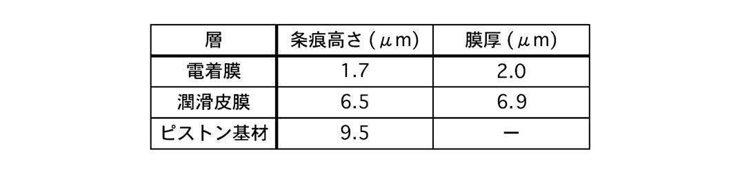
ここで膜厚とは、スカート部外周面120の法線方向において、ある層の皮膜における条痕14の最高部(頂部)から、当該皮膜を覆う次の層の皮膜における条痕14の最高部(頂部)までの距離をいう。なお、膜厚を測定するための基準位置は、条痕14の頂部に限らない。膜厚や条痕14の高さの各数値は、複数の条痕14について平均したものを示す。基材100に加工された条痕140の高さa0は9.5μmだった。潤滑皮膜131の膜厚は6.9μmだった。潤滑皮膜131に形成された条痕141の高さa1は6.5μmだった。電着膜130の膜厚は2.0μmだった。電着膜130に形成された条痕142の高さa2は1.7μmだった。条痕14の高さが電着膜130により低くなる(平滑性が向上する)ことの意味は、実施形態2に準じて理解することができる。a1(=6.5μm)は、「条痕140の高さa0をベースとして潤滑皮膜131の塗料からその揮発成分が揮発することによる条痕141の高さ(1-β)a0」に相当する。a2(=1.7μm)は、「条痕141の高さa1をベースとして電着塗料からその揮発成分が揮発することによる条痕142の高さ(1-α) a1=(1-α) (1-β)a0」よりも低い高さに相当する。
ここで膜厚とは、スカート部外周面120の法線方向において、ある層の皮膜における条痕14の最高部(頂部)から、当該皮膜を覆う次の層の皮膜における条痕14の最高部(頂部)までの距離をいう。なお、膜厚を測定するための基準位置は、条痕14の頂部に限らない。膜厚や条痕14の高さの各数値は、複数の条痕14について平均したものを示す。基材100に加工された条痕140の高さa0は9.5μmだった。潤滑皮膜131の膜厚は6.9μmだった。潤滑皮膜131に形成された条痕141の高さa1は6.5μmだった。電着膜130の膜厚は2.0μmだった。電着膜130に形成された条痕142の高さa2は1.7μmだった。条痕14の高さが電着膜130により低くなる(平滑性が向上する)ことの意味は、実施形態2に準じて理解することができる。a1(=6.5μm)は、「条痕140の高さa0をベースとして潤滑皮膜131の塗料からその揮発成分が揮発することによる条痕141の高さ(1-β)a0」に相当する。a2(=1.7μm)は、「条痕141の高さa1をベースとして電着塗料からその揮発成分が揮発することによる条痕142の高さ(1-α) a1=(1-α) (1-β)a0」よりも低い高さに相当する。
図8のグラフ(直線L)に従えば、流体潤滑摩擦係数は、スカート部外周面120における条痕14の高さがa0(=9.5μm)であるとき略0.012であり、a1(=6.5μm)であるとき0.009であり、a2(=1.7μm)であるとき略0.004である。よって、本実施形態のピストン1では、スカート部外周面120に基材100の条痕140が露出しているもの(以下、比較例1という。)に比べ、条痕14の高さがa0からa2へ低くなることにより、流体潤滑摩擦係数が略1/3まで低下することが分かる。また、スカート部外周面120(基材100)が潤滑皮膜131のみで覆われているもの(以下、比較例2という。)に比べ、条痕14の高さがa1からa2へ低くなることにより、流体潤滑摩擦係数が略4/9まで低下することが分かる。なお、図8のグラフに従えば、流体潤滑摩擦係数は、スカート部外周面120における条痕14の高さが2.0μm以下であるとき、略0.0045以下である。このとき、流体潤滑摩擦係数は、比較例1に比べて略3/8以下まで低下し、比較例2に比べて略半分以下まで低下することが分かる。
表2は、電着条件を変化させたときの条痕142の高さa2を示す実験結果である。条痕140,141の高さa0,a1および潤滑皮膜131の膜厚は、電着条件を60Vで5秒としたときの上記実験結果と同じとした。(表2)
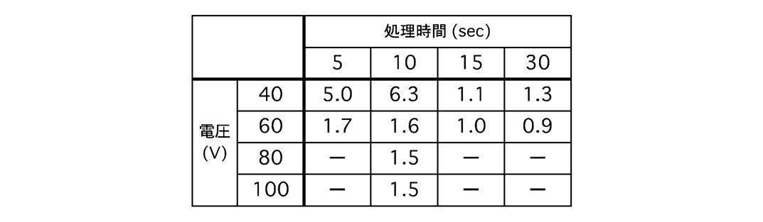
a2は、処理時間(通電時間)を5秒とした場合、電圧が40Vのときは5.0μmとなり、60Vのときは1.7μmとなった。処理時間を10秒とした場合、電圧が40Vのときは6.3μmとなり、60Vのときは1.6μmとなり、80Vおよび100Vのときは1.5μmとなった。なお、a0が7.5μmでありa1が5.3μmである条件下で、a2は、処理時間を15秒とした場合、電圧が40Vのときは1.1μmとなり、60Vのときは1.0μmとなった。同条件下で、a2は、処理時間を30秒とした場合、電圧が40Vのときは1.3μmとなり、60Vのときは0.9μmとなった。a2は、電圧が40Vのときは、処理時間が10秒以下では、条痕141の高さから大きく低下しなかった。電圧が60Vのときは、処理時間が10秒以下であっても、条痕141の高さから大きく低下し、2.0μm以下となった。このように、電圧を60Vよりも大きくしても、処理時間が10秒では、a2は大きく変化しなかった。電圧が60Vのとき、処理時間が5秒でも、10秒のときからa2は大きく変化しなかった。よって、電圧を低く保ち、処理時間を短くし、かつa2を2.0μm以下まで低くするための電着条件は、60Vで5秒であれば足りることが分かった。基材100と電着膜130との間には、潤滑皮膜131が介在する。電着は、潤滑皮膜131に電流が流れ、潤滑皮膜131の表面に電着塗料が析出することで行われる。潤滑皮膜131は、導電性が基材100よりも低く、6.9μmの膜厚で基材100を覆った。この場合であっても、60Vで5秒という電着条件で、上記のように条痕142の高さa2が2.0μm以下まで低い電着膜130が形成されることが分かった。
a2は、処理時間(通電時間)を5秒とした場合、電圧が40Vのときは5.0μmとなり、60Vのときは1.7μmとなった。処理時間を10秒とした場合、電圧が40Vのときは6.3μmとなり、60Vのときは1.6μmとなり、80Vおよび100Vのときは1.5μmとなった。なお、a0が7.5μmでありa1が5.3μmである条件下で、a2は、処理時間を15秒とした場合、電圧が40Vのときは1.1μmとなり、60Vのときは1.0μmとなった。同条件下で、a2は、処理時間を30秒とした場合、電圧が40Vのときは1.3μmとなり、60Vのときは0.9μmとなった。a2は、電圧が40Vのときは、処理時間が10秒以下では、条痕141の高さから大きく低下しなかった。電圧が60Vのときは、処理時間が10秒以下であっても、条痕141の高さから大きく低下し、2.0μm以下となった。このように、電圧を60Vよりも大きくしても、処理時間が10秒では、a2は大きく変化しなかった。電圧が60Vのとき、処理時間が5秒でも、10秒のときからa2は大きく変化しなかった。よって、電圧を低く保ち、処理時間を短くし、かつa2を2.0μm以下まで低くするための電着条件は、60Vで5秒であれば足りることが分かった。基材100と電着膜130との間には、潤滑皮膜131が介在する。電着は、潤滑皮膜131に電流が流れ、潤滑皮膜131の表面に電着塗料が析出することで行われる。潤滑皮膜131は、導電性が基材100よりも低く、6.9μmの膜厚で基材100を覆った。この場合であっても、60Vで5秒という電着条件で、上記のように条痕142の高さa2が2.0μm以下まで低い電着膜130が形成されることが分かった。
電着条件を60Vで5秒としたとき、電着膜130の膜厚は2.0μmだった。この値は、潤滑皮膜131の膜厚(6.9μm)よりも大幅に小さい。このように電着膜130の膜厚の増大が抑制されることで、電着膜130が摩耗しやすくなる。これにより、上記のように初期馴染み性や潤滑性が向上する。なお、初期馴染み性等を向上させるためには、電着膜130の膜厚は、2.0μmに限らず、例えば略3.0μmよりも若干厚くてもよく、好ましくは3μm以下(0μmより大きい)である。
[実施形態4]
まず、構成を説明する。図14は、本実施形態における、ピストン1の軸心Oを含む平面内でのスカート部12の外周側の断面を示す。皮膜部13は、電着膜130を有すると共に、電着膜130とは別に、下層皮膜(第1皮膜)132および上層皮膜(第2皮膜)133を有する。すなわち、ピストン1のスカート部12は3層の皮膜を有する。下層皮膜132および上層皮膜133は、バインダー樹脂と固体潤滑剤を含む潤滑皮膜が複層化したものである。皮膜部13は、基材100の側から電着膜130と下層皮膜132と上層皮膜133とをこの順に有する。電着膜130は基材100を覆う。電着膜130の組成は、実施形態1と同様である。下層皮膜132は、上層皮膜133よりも基材100に近い側すなわち下層側にあり、電着膜130を覆う。下層皮膜132は、バインダー樹脂としてPAIを含む。なお、バインダー樹脂は、PAIと共に、またはPAIに代えて、PIまたはEPの少なくとも一方を含んでもよい。下層皮膜132は、固体潤滑剤としてCを含む。なお、固体潤滑剤は、Cと共に、またはCに代えて、MoS2またはPTFEの少なくとも一方を含んでもよい。下層皮膜132は、固体潤滑剤の含有量が0wt%より大きく50wt%以下であり、バインダー樹脂の含有量が50wt%以上かつ100wt%未満である。上層皮膜133は、下層皮膜132よりも基材100から遠い側すなわち上層側にある。上層皮膜133は下層皮膜132を覆い、スカート部外周面120に露出する。上層皮膜133は、バインダー樹脂としてPAIを含む。なお、バインダー樹脂は、PAIと共に、またはPAIに代えて、PIまたはEPの少なくとも一方を含んでもよい。上層皮膜133は、固体潤滑剤としてMoS2を含む。なお、固体潤滑剤は、MoS2と共に、またはMoS2に代えて、CまたはPTFEの少なくとも一方を含んでもよい。上層皮膜133は、固体潤滑剤の含有量が50wt%以上かつ95wt%以下であり、バインダー樹脂の含有量が5wt%以上かつ50wt%以下である。
まず、構成を説明する。図14は、本実施形態における、ピストン1の軸心Oを含む平面内でのスカート部12の外周側の断面を示す。皮膜部13は、電着膜130を有すると共に、電着膜130とは別に、下層皮膜(第1皮膜)132および上層皮膜(第2皮膜)133を有する。すなわち、ピストン1のスカート部12は3層の皮膜を有する。下層皮膜132および上層皮膜133は、バインダー樹脂と固体潤滑剤を含む潤滑皮膜が複層化したものである。皮膜部13は、基材100の側から電着膜130と下層皮膜132と上層皮膜133とをこの順に有する。電着膜130は基材100を覆う。電着膜130の組成は、実施形態1と同様である。下層皮膜132は、上層皮膜133よりも基材100に近い側すなわち下層側にあり、電着膜130を覆う。下層皮膜132は、バインダー樹脂としてPAIを含む。なお、バインダー樹脂は、PAIと共に、またはPAIに代えて、PIまたはEPの少なくとも一方を含んでもよい。下層皮膜132は、固体潤滑剤としてCを含む。なお、固体潤滑剤は、Cと共に、またはCに代えて、MoS2またはPTFEの少なくとも一方を含んでもよい。下層皮膜132は、固体潤滑剤の含有量が0wt%より大きく50wt%以下であり、バインダー樹脂の含有量が50wt%以上かつ100wt%未満である。上層皮膜133は、下層皮膜132よりも基材100から遠い側すなわち上層側にある。上層皮膜133は下層皮膜132を覆い、スカート部外周面120に露出する。上層皮膜133は、バインダー樹脂としてPAIを含む。なお、バインダー樹脂は、PAIと共に、またはPAIに代えて、PIまたはEPの少なくとも一方を含んでもよい。上層皮膜133は、固体潤滑剤としてMoS2を含む。なお、固体潤滑剤は、MoS2と共に、またはMoS2に代えて、CまたはPTFEの少なくとも一方を含んでもよい。上層皮膜133は、固体潤滑剤の含有量が50wt%以上かつ95wt%以下であり、バインダー樹脂の含有量が5wt%以上かつ50wt%以下である。
ピストン1の表面処理方法(本処理)は、電着膜形成工程と下層皮膜形成工程と上層皮膜形成工程を有する。本処理では、電着膜形成工程と下層皮膜形成工程と上層皮膜形成工程をこの順に行う。電着膜形成工程の手順は、実施形態1と同様である。下層皮膜形成工程および上層皮膜形成工程の手順は、実施形態2の潤滑皮膜形成工程の手順と同様である。なお、電着膜形成工程における焼成工程を乾燥工程に変えてもよいし、下層皮膜形成工程における乾燥工程を焼成工程に変えてもよいし、上層皮膜形成工程における乾燥工程を焼成工程に変えてもよい。各皮膜について乾燥と焼成のどちらを行うかで、全体の皮膜を形成する工程として8通りが考えられる。焼成を1回も行わない(全ての皮膜について乾燥を行う)場合を除くと、全体の皮膜を形成する工程として、7通りが考えられる。本実施形態では、全体の皮膜を形成する代表的な工程として、電着膜形成工程が焼成工程を含み、下層皮膜形成工程および上層皮膜形成工程が乾燥工程を含むものを例示する。
次に、作用効果を説明する。皮膜部13は、下層皮膜132と上層皮膜133とをこの順に有する。上層皮膜133により、実施形態2の潤滑皮膜と同様の作用効果(初期馴染み性等)が得られる。下層皮膜132は、固体潤滑剤を含む(固体潤滑剤の含有量が0wt%より大きい)。よって、第1範囲で、上層皮膜133の摩耗等により、下層皮膜132がスカート部外周面120に露出すれば、実施形態2と同様、下層皮膜132の固体潤滑剤によりスカート部外周面120とシリンダ内壁20との間の摩擦力の大きさが低減される。下層皮膜132は、バインダー樹脂の含有量が50wt%以上(固体潤滑剤の含有量が50wt%以下)である。よって、下層皮膜132の接着力が高く、下層皮膜132と電着膜130との密着性がよい。また、下層皮膜132と上層皮膜133との密着性がよい。
電着膜130により、実施形態2の電着膜130と同様の作用効果(平滑性の向上等)が得られる。すなわち、潤滑皮膜(上層皮膜133)で覆われたスカート部外周面120が平滑化される。3層の皮膜で覆われたスカート部外周面120における条痕14の高さが電着膜130により低くなる(平滑性が向上する)ことの意味は、実施形態1,2に準じて理解することができる。例えば、下層皮膜132における塗料全体の体積に対する固体成分の体積の比をβ、上層皮膜133における塗料全体の体積に対する固体成分の体積の比をγとして、実施形態2と同様に計算すればよい。電着膜130の他に複数(2層)の皮膜132,133を形成することで、スカート部外周面120がより効率的に平滑化される。なお、実施形態2と同様、電着膜130は、電気的絶縁体である固体潤滑剤を含んでもよい。
[実施形態5]
まず、構成を説明する。図15は、本実施形態における、ピストン1の軸心Oを含む平面内でのスカート部12の外周側の断面を示す。実施形態4と同様、スカート部12は3層の皮膜を有する。皮膜部13は、基材100の側から下層皮膜132と電着膜130と上層皮膜133とをこの順に有する。下層皮膜132は基材100を覆う。下層皮膜132の組成は、実施形態3の潤滑皮膜131と同様である。電着膜130は下層皮膜132を覆う。電着膜130の組成は、実施形態1と同様である。上層皮膜133は電着膜130を覆い、スカート部外周面120に露出する。上層皮膜133の組成は、実施形態4と同様である。ピストン1の表面処理方法(本処理)では、下層皮膜形成工程と電着膜形成工程と上層皮膜形成工程をこの順に行う。下層皮膜形成工程の手順は、実施形態3の潤滑皮膜形成工程の手順と同様である。電着膜形成工程の手順は、実施形態3と同様である。上層皮膜形成工程の手順は、実施形態4と同様である。
まず、構成を説明する。図15は、本実施形態における、ピストン1の軸心Oを含む平面内でのスカート部12の外周側の断面を示す。実施形態4と同様、スカート部12は3層の皮膜を有する。皮膜部13は、基材100の側から下層皮膜132と電着膜130と上層皮膜133とをこの順に有する。下層皮膜132は基材100を覆う。下層皮膜132の組成は、実施形態3の潤滑皮膜131と同様である。電着膜130は下層皮膜132を覆う。電着膜130の組成は、実施形態1と同様である。上層皮膜133は電着膜130を覆い、スカート部外周面120に露出する。上層皮膜133の組成は、実施形態4と同様である。ピストン1の表面処理方法(本処理)では、下層皮膜形成工程と電着膜形成工程と上層皮膜形成工程をこの順に行う。下層皮膜形成工程の手順は、実施形態3の潤滑皮膜形成工程の手順と同様である。電着膜形成工程の手順は、実施形態3と同様である。上層皮膜形成工程の手順は、実施形態4と同様である。
次に、作用効果を説明する。上層皮膜133により、実施形態2の潤滑皮膜131と同様の作用効果(初期馴染み性等)が得られる。電着膜130により、実施形態2の電着膜130と同様、潤滑皮膜(上層皮膜133)で覆われたスカート部外周面120(少なくとも第2範囲)が平滑化される。電着膜130は固体潤滑剤を含まない。よって、電着膜130の接着力が高く、電着膜130と下層皮膜132との密着性がよい。また、電着膜130と上層皮膜133との密着性がよい。なお、実施形態2と同様、電着膜130は、電気的絶縁体である固体潤滑剤を含んでもよい。電着膜130は焼成されないため、実施形態3の電着膜130と同様、第1範囲において電着膜130が(上層皮膜133と共に)早期に摩耗して平滑化し、シリンダ内壁20と早急に馴染みやすい。また、電着膜130に覆われた下層皮膜132がスカート部外周面120に露出しやすくなるため、下層皮膜132のメリット(潤滑性や初期馴染み性)が得られやすい。なお、実施形態3と同様、電着膜130に、耐摩耗性が低いバインダー樹脂を含めてもよいし、電気的絶縁体である固体潤滑剤を多く含めてもよい。下層皮膜132により、実施形態3の潤滑皮膜131と同様の作用効果が得られる。
図16は、電着条件を60Vで5秒としたときの実験結果における、図13と同様の断面を示す。表3は、この実験において形成された各皮膜の膜厚と条痕14の高さを示す。条痕140,141,142の高さa0,a1,a2、下層皮膜132および電着膜130の膜厚は、実施形態3における実験結果(図13、表1)と同じとした。(表3)
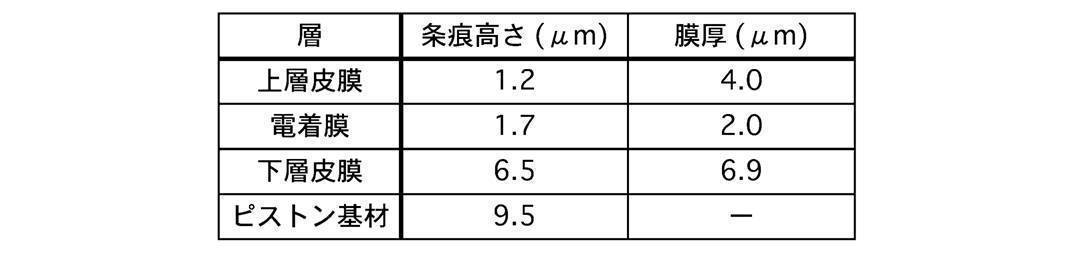
上層皮膜133の膜厚は4.0μmだった。上層皮膜133に形成された条痕143の高さa3は1.2μmだった。a3は、「条痕142の高さa2をベースとして上層皮膜133の塗料からその揮発成分が揮発することにより形成される条痕143の高さ(1-γ) a2」に相当する。上層皮膜133により覆われる分だけ、スカート部外周面120における条痕143の高さa3が実施形態3(条痕142の高さa2=1.7μm)よりも低いことが分かる。
上層皮膜133の膜厚は4.0μmだった。上層皮膜133に形成された条痕143の高さa3は1.2μmだった。a3は、「条痕142の高さa2をベースとして上層皮膜133の塗料からその揮発成分が揮発することにより形成される条痕143の高さ(1-γ) a2」に相当する。上層皮膜133により覆われる分だけ、スカート部外周面120における条痕143の高さa3が実施形態3(条痕142の高さa2=1.7μm)よりも低いことが分かる。
図8のグラフ(直線L)のグラフに従えば、流体潤滑摩擦係数は、スカート部外周面120における条痕14の高さがa3(=1.2μm)であるとき略0.0037である。よって、本実施形態のピストン1では、上記比較例1に比べ、条痕14の高さがa0からa3へ低くなることにより、流体潤滑摩擦係数が略30%まで低下することが分かる。また、上記比較例2に比べ、条痕14の高さがa1からa3へ低くなることにより、流体潤滑摩擦係数が略40%まで低下することが分かる。
電着膜130の膜厚は3μm以下だった。このように電着膜130の膜厚の増大が抑制されることで、電着膜130が摩耗しやすくなる。これにより、上記のように初期馴染み性や潤滑性が向上する。なお、初期馴染み性等を向上させるためには、電着膜130の膜厚は、例えば略3.0μmよりも若干厚くてもよい。
[実施形態6]
まず、構成を説明する。図17は、本実施形態における、ピストン1の軸心Oを含む平面内でのスカート部12の外周側の断面を示す。実施形態4と同様、スカート部12は3層の皮膜を有する。皮膜部13は、基材100の側から下層皮膜132と上層皮膜133と電着膜130とをこの順に有する。下層皮膜132は基材100を覆う。下層皮膜132の組成は、実施形態3の潤滑皮膜131と同様である。上層皮膜133は下層皮膜132を覆う。上層皮膜133の組成は、実施形態4と同様である。上層皮膜133は、固体潤滑剤としてMoS2を含む。なお、固体潤滑剤は、MoS2と共に、またはMoS2に代えて、Cを含んでもよいが、PTFEを含まない。電着膜130は上層皮膜133を覆い、スカート部外周面120に露出する。電着膜130の組成は、実施形態1と同様である。ピストン1の表面処理方法(本処理)では、下層皮膜形成工程と上層皮膜形成工程と電着膜形成工程をこの順に行う。下層皮膜形成工程および上層皮膜形成工程の手順は、実施形態3の潤滑皮膜形成工程の手順と同様である。例えば、下層皮膜形成工程における焼成工程後、ピストン1の温度が50℃~120℃にあるとき、上層皮膜形成工程における塗装工程を行う。電着膜形成工程の手順は、実施形態3と同様である。
まず、構成を説明する。図17は、本実施形態における、ピストン1の軸心Oを含む平面内でのスカート部12の外周側の断面を示す。実施形態4と同様、スカート部12は3層の皮膜を有する。皮膜部13は、基材100の側から下層皮膜132と上層皮膜133と電着膜130とをこの順に有する。下層皮膜132は基材100を覆う。下層皮膜132の組成は、実施形態3の潤滑皮膜131と同様である。上層皮膜133は下層皮膜132を覆う。上層皮膜133の組成は、実施形態4と同様である。上層皮膜133は、固体潤滑剤としてMoS2を含む。なお、固体潤滑剤は、MoS2と共に、またはMoS2に代えて、Cを含んでもよいが、PTFEを含まない。電着膜130は上層皮膜133を覆い、スカート部外周面120に露出する。電着膜130の組成は、実施形態1と同様である。ピストン1の表面処理方法(本処理)では、下層皮膜形成工程と上層皮膜形成工程と電着膜形成工程をこの順に行う。下層皮膜形成工程および上層皮膜形成工程の手順は、実施形態3の潤滑皮膜形成工程の手順と同様である。例えば、下層皮膜形成工程における焼成工程後、ピストン1の温度が50℃~120℃にあるとき、上層皮膜形成工程における塗装工程を行う。電着膜形成工程の手順は、実施形態3と同様である。
次に、作用効果を説明する。電着膜130により、実施形態3の電着膜130と同様の作用効果(外周面120の平滑化等)が得られる。第1範囲で、電着膜130の摩耗等により、上層皮膜133がスカート部外周面120に露出すれば、上層皮膜133の固体潤滑剤により摩擦力の大きさが低減されると共に、上層皮膜133が早期に摩耗することで初期馴染み性がよくなる。第1範囲で、電着膜130および上層皮膜133の摩耗等により、下層皮膜132がスカート部外周面120に露出すれば、下層皮膜132の固体潤滑剤により摩擦力の大きさが低減される。
下層皮膜132は、バインダー樹脂の含有量が50wt%以上(固体潤滑剤の含有量が50wt%以下)である。よって、下層皮膜132の接着力が高く、下層皮膜132と基材100との密着性がよい。また、下層皮膜132と上層皮膜133との密着性がよい。下層皮膜132および上層皮膜133に含まれる固体潤滑剤は、CやMoS2であり、導電性を有する。よって、電着塗装工程において、下層皮膜132および上層皮膜133に覆われたスカート部外周面120を電極として機能させ、上層皮膜133の上に電着膜130を形成することが容易である。
図18は、電着条件を100Vで10秒としたときの実験結果における、図13と同様の断面を示す。表4は、この実験において形成された各皮膜の膜厚と条痕14の高さを示す。(表4)
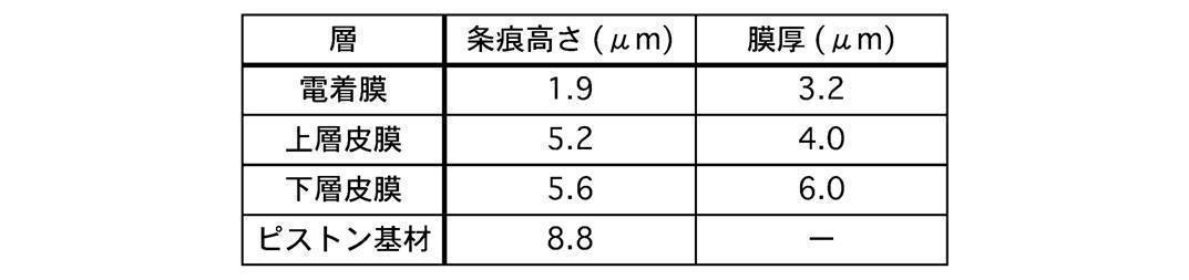
条痕140の高さa0は8.8μmだった。下層皮膜132の膜厚は6.0μmだった。下層皮膜132に形成された条痕141の高さa1は5.6μmだった。上層皮膜133の膜厚は4.0μmだった。上層皮膜133に形成された条痕142の高さa2は5.2μmだった。電着膜130の膜厚は3.2μmだった。電着膜130に形成された条痕143の高さa3は1.9μmだった。a1(=5.6μm)は、「条痕140の高さa0をベースとして下層皮膜132の塗料からその揮発成分が揮発することによる条痕141の高さ(1-β)a0」に相当する。a2(=5.2μm)は、「条痕141の高さa1をベースとして上層皮膜133の塗料からその揮発成分が揮発することによる条痕142の高さ(1-γ) a1= (1-β) (1-γ) a0」に相当する。a3(=1.9μm)は、「条痕142の高さa2をベースとして電着塗料からその揮発成分が揮発することによる条痕143の高さ(1-α) a2=(1-α) (1-β) (1-γ)a0」よりも低い高さに相当する。
条痕140の高さa0は8.8μmだった。下層皮膜132の膜厚は6.0μmだった。下層皮膜132に形成された条痕141の高さa1は5.6μmだった。上層皮膜133の膜厚は4.0μmだった。上層皮膜133に形成された条痕142の高さa2は5.2μmだった。電着膜130の膜厚は3.2μmだった。電着膜130に形成された条痕143の高さa3は1.9μmだった。a1(=5.6μm)は、「条痕140の高さa0をベースとして下層皮膜132の塗料からその揮発成分が揮発することによる条痕141の高さ(1-β)a0」に相当する。a2(=5.2μm)は、「条痕141の高さa1をベースとして上層皮膜133の塗料からその揮発成分が揮発することによる条痕142の高さ(1-γ) a1= (1-β) (1-γ) a0」に相当する。a3(=1.9μm)は、「条痕142の高さa2をベースとして電着塗料からその揮発成分が揮発することによる条痕143の高さ(1-α) a2=(1-α) (1-β) (1-γ)a0」よりも低い高さに相当する。
図8のグラフ(直線L)のグラフに従えば、流体潤滑摩擦係数は、スカート部外周面120における条痕14の高さがa0(=8.8μm)であるとき略0.011であり、a2(=5.2μm)であるとき0.008であり、a3(=1.9μm)であるとき略0.004である。よって、本実施形態のピストン1では、比較例1に比べ、条痕14の高さがa0からa3へ低くなることにより、流体潤滑摩擦係数が略40%まで低下することが分かる。また、スカート部外周面120(基材100)が潤滑皮膜132,133のみに覆われているものに比べ、条痕14の高さがa2からa3へ低くなることにより、流体潤滑摩擦係数が略半分まで低下することが分かる。
表5は、電着条件を変化させたときの条痕143の高さa3を示す実験結果である。条痕140~142の高さa0~a2および潤滑皮膜132,133の膜厚は、電着条件を100Vで10秒としたときの上記実験結果と同じとした。(表5)

a3は、処理時間を5秒とした場合、電圧が60Vのときは5.0μmとなり、80Vのときは4.4μmとなり、100Vのときは3.4μmとなり、120Vのときは3.8μmとなった。a3は、処理時間を10秒とした場合、電圧が60Vのときは4.4μmとなり、80Vのときは3.9μmとなり、100Vのときは1.9μmとなり、120Vのときは5.0μmとなった。このように、a3は、電圧が100V以下のときは、処理時間に関わらず、電圧が高くなるほど低くなった。電圧が120Vのときは、処理時間に関わらず、100Vのときよりもa3が高くなった。電圧が100V以下の場合、処理時間が10秒のときは、5秒のときのときよりも、a3は低くなった。60Vで5秒では、a3は5.0μmとなり、a2(=5.2μm)からほとんど低くならなかった。60Vで5秒では、a3を低くするために電着膜130の生成が不十分であることが分かった。100Vで10秒であれば、a3を2.0μm以下まで低くできることが分かった。基材100と電着膜130との間には、潤滑皮膜(下層皮膜132および上層皮膜133)が介在する。電着は、潤滑皮膜132,133に電流が流れ、上層皮膜133の表面に電着塗料が析出することで行われる。潤滑皮膜132,133は、導電性が基材100よりも低く、基材100を10.0μm(=6.0μm+4.0μm)の膜厚で覆った。この場合でも、100Vで10秒という電着条件で、上記のように条痕143の高さa3が2.0μm以下まで低い電着膜130が形成されることが分かった。
a3は、処理時間を5秒とした場合、電圧が60Vのときは5.0μmとなり、80Vのときは4.4μmとなり、100Vのときは3.4μmとなり、120Vのときは3.8μmとなった。a3は、処理時間を10秒とした場合、電圧が60Vのときは4.4μmとなり、80Vのときは3.9μmとなり、100Vのときは1.9μmとなり、120Vのときは5.0μmとなった。このように、a3は、電圧が100V以下のときは、処理時間に関わらず、電圧が高くなるほど低くなった。電圧が120Vのときは、処理時間に関わらず、100Vのときよりもa3が高くなった。電圧が100V以下の場合、処理時間が10秒のときは、5秒のときのときよりも、a3は低くなった。60Vで5秒では、a3は5.0μmとなり、a2(=5.2μm)からほとんど低くならなかった。60Vで5秒では、a3を低くするために電着膜130の生成が不十分であることが分かった。100Vで10秒であれば、a3を2.0μm以下まで低くできることが分かった。基材100と電着膜130との間には、潤滑皮膜(下層皮膜132および上層皮膜133)が介在する。電着は、潤滑皮膜132,133に電流が流れ、上層皮膜133の表面に電着塗料が析出することで行われる。潤滑皮膜132,133は、導電性が基材100よりも低く、基材100を10.0μm(=6.0μm+4.0μm)の膜厚で覆った。この場合でも、100Vで10秒という電着条件で、上記のように条痕143の高さa3が2.0μm以下まで低い電着膜130が形成されることが分かった。
電着条件を100Vで10秒としたとき、形成される電着膜130の膜厚は3.2μmだった。この値は、潤滑皮膜132,133の膜厚(10.0μm)よりも大幅に小さい。このように電着膜130の膜厚の増大が抑制されることで、電着膜130が摩耗しやすくなる。これにより、上記のように初期馴染み性や潤滑性が向上する。なお、実施形態3と同様、電着膜130に、耐摩耗性が低いバインダー樹脂を含めてもよいし、電気的絶縁体である固体潤滑剤を多く含めてもよい。
[他の実施形態]
以上、本発明を実施するための形態を、実施形態に基づいて説明してきたが、本発明の具体的な構成は実施形態に限定されるものではなく、発明の要旨を逸脱しない範囲の設計変更等があっても、本発明に含まれる。例えば、ピストンの基材は、アルミニウム合金に限らず、鉄等でもよい。PAI、PI、およびEPは密着性に優れることから、基材によらず適用可能である。また、上述した課題の少なくとも一部を解決できる範囲、または、効果の少なくとも一部を奏する範囲において、特許請求の範囲および明細書に記載された各構成要素の任意の組み合わせ、または、省略が可能である。
以上、本発明を実施するための形態を、実施形態に基づいて説明してきたが、本発明の具体的な構成は実施形態に限定されるものではなく、発明の要旨を逸脱しない範囲の設計変更等があっても、本発明に含まれる。例えば、ピストンの基材は、アルミニウム合金に限らず、鉄等でもよい。PAI、PI、およびEPは密着性に優れることから、基材によらず適用可能である。また、上述した課題の少なくとも一部を解決できる範囲、または、効果の少なくとも一部を奏する範囲において、特許請求の範囲および明細書に記載された各構成要素の任意の組み合わせ、または、省略が可能である。
本願は、2015年3月23日出願の日本特許出願番号2015-059906号に基づく優先権を主張する。2015年3月23日出願の日本特許出願番号2015-059906号の明細書、特許請求の範囲、図面及び要約書を含む全ての開示内容は、参照により全体として本願に組み込まれる。
1 ピストン、100 基材、12 スカート部、120 外周面、13 皮膜、130 電着膜、132 下層皮膜(第1皮膜)、133 上層皮膜(第2皮膜)、14 条痕、2 シリンダ、20 内壁
Claims (11)
- 内燃機関のピストンであって、
シリンダの内壁に対向するスカート部の外周側に設けられた電着膜を有する内燃機関のピストン。 - 請求項1に記載の内燃機関のピストンにおいて、
前記ピストンの基材は、前記スカート部の外周側に条痕を備える
内燃機関のピストン。 - 請求項2に記載の内燃機関のピストンは、前記電着膜に加えて更に、第1皮膜と第2皮膜とを備え、
前記第1皮膜および前記第2皮膜は、前記ピストンの基材の側から見て、該第1皮膜、該第2皮膜の順に配置され、
前記第1皮膜および前記第2皮膜はバインダー樹脂を含み、
前記第1皮膜における固体潤滑剤の含有量が50重量%以下であり、
前記第2皮膜における固体潤滑剤の含有量が50重量%以上かつ95重量%以下である
内燃機関のピストン。 - 請求項3に記載の内燃機関のピストンにおいて、
前記第1皮膜、前記第2皮膜および前記電着膜は、前記ピストンの基材の側から見て、該第1皮膜、該電着膜、該第2皮膜の順に配置された
内燃機関のピストン。 - 請求項4に記載の内燃機関のピストンにおいて、
前記電着膜は、固体潤滑剤を含まないか、または、電気的絶縁性を有する固体潤滑剤を含む
内燃機関のピストン。 - 請求項3に記載の内燃機関のピストンにおいて、
前記第1皮膜、前記第2皮膜および前記電着膜は、前記ピストンの基材の側から見て、該第1皮膜、該第2皮膜、該電着膜の順に配置された
内燃機関のピストン。 - 請求項2に記載の内燃機関のピストンは、前記電着膜に加えて更に、皮膜を備え、
前記皮膜は、バインダー樹脂を含み、
固体潤滑剤の含有量が50重量%以下である
内燃機関のピストン。 - 内燃機関のピストンであって、
シリンダの内壁に対向するスカート部の外周側に設けられ、塗料の電着によって形成された皮膜を有する
内燃機関のピストン。 - 内燃機関のピストンの表面処理方法であって、
シリンダの内壁に対向するスカート部の外周側に塗料の電着により皮膜を形成する工程を備える
内燃機関のピストンの表面処理方法。 - 請求項9に記載の内燃機関のピストンの表面処理方法において、
前記電着により形成された前記皮膜を焼成することなく前記表面処理を終了する工程を備える
内燃機関のピストンの表面処理方法。 - 請求項10に記載の内燃機関のピストンにおいて、
前記塗料は、固体潤滑剤を含まないか、または、電気的絶縁性を有する固体潤滑剤を含む
内燃機関のピストンの表面処理方法。
Priority Applications (2)
| Application Number | Priority Date | Filing Date | Title |
|---|---|---|---|
| CN201680015171.9A CN107429632A (zh) | 2015-03-23 | 2016-03-07 | 内燃机的活塞和内燃机的活塞的表面处理方法 |
| US15/552,826 US20180038309A1 (en) | 2015-03-23 | 2016-03-07 | Piston of internal combustion engine or method for processing surface of piston of internal combustion engine |
Applications Claiming Priority (2)
| Application Number | Priority Date | Filing Date | Title |
|---|---|---|---|
| JP2015059906A JP6485952B2 (ja) | 2015-03-23 | 2015-03-23 | 内燃機関のピストンまたは内燃機関のピストンの表面処理方法 |
| JP2015-059906 | 2015-03-23 |
Publications (1)
| Publication Number | Publication Date |
|---|---|
| WO2016152468A1 true WO2016152468A1 (ja) | 2016-09-29 |
Family
ID=56979131
Family Applications (1)
| Application Number | Title | Priority Date | Filing Date |
|---|---|---|---|
| PCT/JP2016/056914 Ceased WO2016152468A1 (ja) | 2015-03-23 | 2016-03-07 | 内燃機関のピストンまたは内燃機関のピストンの表面処理方法 |
Country Status (4)
| Country | Link |
|---|---|
| US (1) | US20180038309A1 (ja) |
| JP (1) | JP6485952B2 (ja) |
| CN (1) | CN107429632A (ja) |
| WO (1) | WO2016152468A1 (ja) |
Families Citing this family (4)
| Publication number | Priority date | Publication date | Assignee | Title |
|---|---|---|---|---|
| JP6915472B2 (ja) * | 2017-09-22 | 2021-08-04 | 日本電産株式会社 | ベースプレート、ハードディスク装置および製造方法 |
| JP2019149218A (ja) * | 2018-02-28 | 2019-09-05 | 日本電産株式会社 | ベースプレートおよびベースプレートの製造方法 |
| EP4219928B1 (en) | 2021-12-14 | 2025-07-30 | Yamaha Hatsudoki Kabushiki Kaisha | Internal combustion engine and transportation device |
| US11680174B1 (en) * | 2022-02-04 | 2023-06-20 | Mazda Motor Corporation | Coating composition, coating film forming method, and engine component |
Citations (5)
| Publication number | Priority date | Publication date | Assignee | Title |
|---|---|---|---|---|
| US4075934A (en) * | 1975-12-29 | 1978-02-28 | Karl Schmidt Gmbh | Piston for internal combustion engines |
| JPH0797517A (ja) * | 1993-08-03 | 1995-04-11 | Toyota Motor Corp | 摺動用樹脂組成物 |
| JP2008088416A (ja) * | 2006-09-04 | 2008-04-17 | Okitsumo Kk | 耐摩耗性の低摩擦抵抗電着塗膜 |
| JP2013142111A (ja) * | 2012-01-11 | 2013-07-22 | Okitsumo Kk | 車輌部品用低voc電着塗料組成物 |
| JP2013167182A (ja) * | 2012-02-15 | 2013-08-29 | Hitachi Automotive Systems Ltd | 内燃機関のピストンの製造方法 |
Family Cites Families (6)
| Publication number | Priority date | Publication date | Assignee | Title |
|---|---|---|---|---|
| JP2687076B2 (ja) * | 1992-12-10 | 1997-12-08 | 本田技研工業株式会社 | 摺動部材 |
| US5486299A (en) * | 1993-11-02 | 1996-01-23 | Dow Corning Asia, Ltd | Wear-resistant lubricant composition |
| KR101277115B1 (ko) * | 2006-07-25 | 2013-06-20 | 페더럴-모걸 코오포레이숀 | 피도금물품을 도금하는 방법 및 장치 |
| CN101113754A (zh) * | 2006-07-28 | 2008-01-30 | 日本电产三协株式会社 | 转轴及具有转轴的马达 |
| DE102008055194A1 (de) * | 2008-12-30 | 2010-07-08 | Federal-Mogul Wiesbaden Gmbh | Gleitelement |
| JP5248379B2 (ja) * | 2009-03-17 | 2013-07-31 | 日立オートモティブシステムズ株式会社 | 複層被膜組成物が施された内燃機関のピストン及び該ピストンの表面処理方法 |
-
2015
- 2015-03-23 JP JP2015059906A patent/JP6485952B2/ja not_active Expired - Fee Related
-
2016
- 2016-03-07 WO PCT/JP2016/056914 patent/WO2016152468A1/ja not_active Ceased
- 2016-03-07 CN CN201680015171.9A patent/CN107429632A/zh active Pending
- 2016-03-07 US US15/552,826 patent/US20180038309A1/en not_active Abandoned
Patent Citations (5)
| Publication number | Priority date | Publication date | Assignee | Title |
|---|---|---|---|---|
| US4075934A (en) * | 1975-12-29 | 1978-02-28 | Karl Schmidt Gmbh | Piston for internal combustion engines |
| JPH0797517A (ja) * | 1993-08-03 | 1995-04-11 | Toyota Motor Corp | 摺動用樹脂組成物 |
| JP2008088416A (ja) * | 2006-09-04 | 2008-04-17 | Okitsumo Kk | 耐摩耗性の低摩擦抵抗電着塗膜 |
| JP2013142111A (ja) * | 2012-01-11 | 2013-07-22 | Okitsumo Kk | 車輌部品用低voc電着塗料組成物 |
| JP2013167182A (ja) * | 2012-02-15 | 2013-08-29 | Hitachi Automotive Systems Ltd | 内燃機関のピストンの製造方法 |
Also Published As
| Publication number | Publication date |
|---|---|
| JP2016180331A (ja) | 2016-10-13 |
| US20180038309A1 (en) | 2018-02-08 |
| CN107429632A (zh) | 2017-12-01 |
| JP6485952B2 (ja) | 2019-03-20 |
Similar Documents
| Publication | Publication Date | Title |
|---|---|---|
| JP6485952B2 (ja) | 内燃機関のピストンまたは内燃機関のピストンの表面処理方法 | |
| US9982715B2 (en) | Sliding engine component | |
| CN100532872C (zh) | 轴承元件 | |
| US10746128B2 (en) | Cylinder bore having variable coating | |
| US2807511A (en) | Coated piston ring | |
| JP5903391B2 (ja) | 摺動部材の製造方法 | |
| JP5248379B2 (ja) | 複層被膜組成物が施された内燃機関のピストン及び該ピストンの表面処理方法 | |
| US2817562A (en) | Coated piston | |
| US9562565B2 (en) | Sliding bearing | |
| JPH01206162A (ja) | ピストン−ピストンリングアッセンブリ | |
| KR20130142959A (ko) | 실린더 라이너용 가변 두께 코팅 | |
| KR20110042117A (ko) | 복합층을 가지는 슬라이딩 요소 | |
| JP7592490B2 (ja) | ピストンリング | |
| BRPI0922557B1 (pt) | Material de plástico para rolamento à base de polímeros | |
| CN105925347A (zh) | 润滑膜用组合物,使用润滑膜用组合物的滑动元件,和生产润滑膜用组合物的方法 | |
| DE112007002854T5 (de) | Kolbenring | |
| US20130091980A1 (en) | Thermal spray coating for connecting rod small end | |
| CN1062940C (zh) | 内燃机的活塞及其制造方法 | |
| WO2016059237A2 (de) | Beschichtung für bauteile von brennkraftmaschinen | |
| EP2971718B1 (de) | Beschichtete kolben und verfahren zu ihrer herstellung | |
| US12209611B2 (en) | Bearing material and solid lubricant | |
| US20190323557A1 (en) | Sliding element for an engine | |
| DE102016108088A1 (de) | Beschichteter Kolbenring mit Schutzschicht | |
| CN114616404B (zh) | 包含聚合物上覆层的滑动元件 | |
| JP6460333B2 (ja) | 内燃機関のピストンおよび内燃機関のピストンの表面処理方法 |
Legal Events
| Date | Code | Title | Description |
|---|---|---|---|
| 121 | Ep: the epo has been informed by wipo that ep was designated in this application |
Ref document number: 16768371 Country of ref document: EP Kind code of ref document: A1 |
|
| WWE | Wipo information: entry into national phase |
Ref document number: 15552826 Country of ref document: US |
|
| NENP | Non-entry into the national phase |
Ref country code: DE |
|
| 122 | Ep: pct application non-entry in european phase |
Ref document number: 16768371 Country of ref document: EP Kind code of ref document: A1 |