WO2016152139A1 - 過給装置 - Google Patents
過給装置 Download PDFInfo
- Publication number
- WO2016152139A1 WO2016152139A1 PCT/JP2016/001622 JP2016001622W WO2016152139A1 WO 2016152139 A1 WO2016152139 A1 WO 2016152139A1 JP 2016001622 W JP2016001622 W JP 2016001622W WO 2016152139 A1 WO2016152139 A1 WO 2016152139A1
- Authority
- WO
- WIPO (PCT)
- Prior art keywords
- back surface
- shaft
- compressor wheel
- bearing
- supercharging device
- Prior art date
- Legal status (The legal status is an assumption and is not a legal conclusion. Google has not performed a legal analysis and makes no representation as to the accuracy of the status listed.)
- Ceased
Links
Images


Classifications
-
- F—MECHANICAL ENGINEERING; LIGHTING; HEATING; WEAPONS; BLASTING
- F02—COMBUSTION ENGINES; HOT-GAS OR COMBUSTION-PRODUCT ENGINE PLANTS
- F02B—INTERNAL-COMBUSTION PISTON ENGINES; COMBUSTION ENGINES IN GENERAL
- F02B33/00—Engines characterised by provision of pumps for charging or scavenging
- F02B33/32—Engines with pumps other than of reciprocating-piston type
- F02B33/34—Engines with pumps other than of reciprocating-piston type with rotary pumps
- F02B33/40—Engines with pumps other than of reciprocating-piston type with rotary pumps of non-positive-displacement type
-
- F—MECHANICAL ENGINEERING; LIGHTING; HEATING; WEAPONS; BLASTING
- F02—COMBUSTION ENGINES; HOT-GAS OR COMBUSTION-PRODUCT ENGINE PLANTS
- F02B—INTERNAL-COMBUSTION PISTON ENGINES; COMBUSTION ENGINES IN GENERAL
- F02B39/00—Component parts, details, or accessories relating to, driven charging or scavenging pumps, not provided for in groups F02B33/00 - F02B37/00
- F02B39/02—Drives of pumps; Varying pump drive gear ratio
- F02B39/08—Non-mechanical drives, e.g. fluid drives having variable gear ratio
- F02B39/10—Non-mechanical drives, e.g. fluid drives having variable gear ratio electric
-
- F—MECHANICAL ENGINEERING; LIGHTING; HEATING; WEAPONS; BLASTING
- F04—POSITIVE - DISPLACEMENT MACHINES FOR LIQUIDS; PUMPS FOR LIQUIDS OR ELASTIC FLUIDS
- F04D—NON-POSITIVE-DISPLACEMENT PUMPS
- F04D25/00—Pumping installations or systems
- F04D25/02—Units comprising pumps and their driving means
- F04D25/06—Units comprising pumps and their driving means the pump being electrically driven
-
- F—MECHANICAL ENGINEERING; LIGHTING; HEATING; WEAPONS; BLASTING
- F04—POSITIVE - DISPLACEMENT MACHINES FOR LIQUIDS; PUMPS FOR LIQUIDS OR ELASTIC FLUIDS
- F04D—NON-POSITIVE-DISPLACEMENT PUMPS
- F04D29/00—Details, component parts, or accessories
- F04D29/08—Sealings
- F04D29/10—Shaft sealings
- F04D29/102—Shaft sealings especially adapted for elastic fluid pumps
-
- F—MECHANICAL ENGINEERING; LIGHTING; HEATING; WEAPONS; BLASTING
- F04—POSITIVE - DISPLACEMENT MACHINES FOR LIQUIDS; PUMPS FOR LIQUIDS OR ELASTIC FLUIDS
- F04D—NON-POSITIVE-DISPLACEMENT PUMPS
- F04D29/00—Details, component parts, or accessories
- F04D29/26—Rotors specially for elastic fluids
- F04D29/28—Rotors specially for elastic fluids for centrifugal or helico-centrifugal pumps for radial-flow or helico-centrifugal pumps
- F04D29/284—Rotors specially for elastic fluids for centrifugal or helico-centrifugal pumps for radial-flow or helico-centrifugal pumps for compressors
Definitions
- the present disclosure relates to a supercharging device that supercharges intake air supplied to an engine (internal combustion engine).
- an engine internal combustion engine
- a surface of the compressor wheel close to the bearing is referred to as a back surface
- a surface far from the bearing is referred to as a surface
- a direction in which the central axis of the shaft extends is referred to as an axial direction.
- Patent Document 1 a supercharging device in which a compressor wheel is fixed to a free end side of a shaft is known (for example, see Patent Document 1).
- the supercharging device of Patent Document 1 is an electric supercharger that combines a centrifugal intake compressor and an electric motor, and a shaft to which a compressor wheel is fixed is an output shaft of the electric motor, and two or more bearings Is rotatably supported by.
- a seal portion is provided between the housing that supports the bearing and the shaft to prevent dust and the like from entering the bearing from around the axis of the compressor wheel.
- the electric supercharger has been described above as an example, the same problem occurs in the turbocharger. Specifically, in the case of an electric supercharger, it is necessary to increase the primary resonance frequency in order to increase the rotation speed of the shaft. On the other hand, in the case of a turbocharger, it is desired to increase the third-order resonance frequency in the overhang range in order to increase the shaft rotation and improve safety. As described above, it is effective to shorten the overhang in order to increase the third-order resonance frequency, but the overhang becomes longer due to the seal portion, and it becomes difficult to increase the third-order resonance frequency. Yes.
- the present disclosure has been made in view of the above problems, and an object thereof is to provide a supercharging device capable of shortening an overhang even in a structure in which a seal portion is interposed between a bearing and a compressor wheel. .
- one aspect of the present disclosure employs a configuration in which a concave portion is provided on the back surface of the compressor wheel so that the concave portion and the seal portion overlap in the axial direction.
- the supercharging device when the supercharging pressure of the supercharging device is made equal to the conventional one, the supercharging device can be downsized. In other words, by adopting this aspect, it becomes possible to increase the output or reduce the size of a supercharger (electric supercharger or turbocharger) using a centrifugal intake compressor.
- a supercharger electric supercharger or turbocharger
- FIG. 2A is a main part sectional view of the supercharging device of the first embodiment
- FIG. 2B is a main part sectional view of the conventional supercharging device.
- It is principal part sectional drawing of a supercharging apparatus (Example 2).
- Example 3 which is principal part sectional drawing of a supercharging device.
- Example 4 which is principal part sectional drawing of a supercharging device.
- Example 1 An electric supercharger 2 is mounted on an engine 1 for vehicle travel (an internal combustion engine that generates rotational power by burning fuel, regardless of the type of fuel or the engine type).
- the engine 1 includes an intake passage 3 that guides intake air into the engine cylinder.
- the electric supercharger 2 includes a centrifugal intake compressor 4 disposed in the middle of the intake passage 3 and an electric motor 5 that drives the intake compressor 4.
- the intake compressor 4 includes a compressor wheel 6 that is driven by the rotational force generated by the electric motor 5 to pressurize the intake air, and a spiral compressor casing 7 that is interposed in the intake passage 3 and accommodates the compressor wheel 6. .
- the electric motor 5 is a well-known electric motor that converts electric power into rotational output, and the specific model is not limited, but a three-phase squirrel-cage induction motor or the like is used as an example.
- the electric motor 5 is energized and controlled by a known control device 10.
- the control device 10 controls the electric motor 5 by controlling an inverter 12 that converts DC power supplied from a power source 11 (such as an in-vehicle battery or an alternator) into AC, and a switching state of the inverter 12.
- ECU13 which changes arbitrarily the voltage and frequency which are given.
- the ECU 13 is an engine control unit that performs fuel injection control of the engine 1, and controls the number of revolutions of the electric motor 5 via the inverter 12 according to the operating state of the engine 1, thereby depending on the operating state of the engine 1. Generate a supercharging pressure.
- the electric motor 5 includes, as a mechanical structure, a shaft 14 that is rotatably supported, a rotor that rotates integrally with the shaft 14, a stator that rotates in cooperation with the rotor, a rotor and a stator. And a housing 15 for housing the housing.
- the housing 15 includes two bearings 16 spaced apart in the axial direction. In FIG. 2, only the bearing 16 on the side close to the compressor wheel 6 is shown.
- the bearing 16 supported by the housing 15 is for rotatably supporting the shaft 14 and may be a rolling bearing such as a ball bearing or a metal bearing that supports the shaft 14 by sliding. good.
- the shaft 14 includes a portion that protrudes to the outside of the housing 15 (hereinafter referred to as a shaft protruding portion).
- the shaft protrusion is a portion where the compressor wheel 6 is assembled, and is provided with a male screw and a step for coupling the compressor wheel 6.
- the male screw is provided at the tip of the shaft protrusion (the right end portion in FIG. 2A).
- the step is provided on the housing 15 side (left side of FIG. 2A) from the male screw, and the male screw side (right side of FIG. 2A) is provided with a small diameter from the step.
- the shaft 14 on the left side of the figure from the step is referred to as a large diameter shaft, and the shaft 14 on the right side of the figure from the step is referred to as a small diameter shaft.
- the compressor wheel 6 is manufactured by metal cutting or the like (not limited), and includes a base portion 17 having a substantially conical shape and a plurality of compressor blades 18 that drive intake air by rotation. Further, a through hole for attaching the compressor wheel 6 to the shaft 14 is formed at the center of the compressor wheel 6.
- a wheel-side step that is in pressure contact with the step in the axial direction is provided, and the surface side (the right side in FIG. 2A) is provided with a smaller diameter than the wheel-side step.
- the through hole on the left side of the figure from the wheel side step is referred to as a large diameter hole
- the through hole on the right side of the figure from the wheel side step is referred to as a small diameter hole.
- at least one of the “large diameter shaft and large diameter hole” or the “small diameter shaft and small diameter hole” is provided to have substantially the same diameter so that the shaft 14 and the axis of the compressor wheel 6 coincide with each other.
- a screw seat surface 22 that receives a fastening force from a nut 21 that is screwed to the tip of the shaft 14 is provided at the center of the front surface side of the compressor wheel 6.
- the screw seat surface 22 is a flat portion perpendicular to the axial direction, and is provided on the top of the base portion 17.
- the compressor wheel 6 is assembled to the shaft protruding portion of the shaft 14, and the nut 21 is fastened to the male screw at the tip of the shaft 14, so that the compressor wheel 6 is coupled to the shaft 14.
- the electric supercharger 2 is an example of a supercharging device. As described above, the shaft 14 that is rotationally driven, the bearing 16 that rotatably supports the shaft 14, and the housing 15 that supports the bearing 16, And the compressor wheel 6 fixed to the free end side of the shaft 14 from the bearing 16.
- the electric supercharger 2 employs a structure in which the shaft 14 and the housing 15 are sealed by a seal portion 23 disposed on the compressor wheel 6 side (right side in the drawing) from the bearing 16. That is, the seal portion 23 is disposed between the housing 15 and the shaft 14 to prevent foreign matters such as dust from entering the bearing 16 from around the axis of the compressor wheel 6.
- the seal portion 23 is a well-known one such as a lip seal or dust seal, and does not limit the structure or the like.
- the seal portion 23 is disposed between the bearing 16 and the compressor wheel 6, so that the overhang L becomes long and the primary resonance in the overhang range. It was an impediment to increasing the frequency.
- the center portion of the back surface of the compressor wheel 6 is recessed toward the front surface side as compared with the periphery of the back surface.
- a configuration is adopted in which a concave portion 24 is provided and the concave portion 24 and the seal portion 23 are overlapped in the axial direction.
- the surface on the outer diameter side from the recess 24 is referred to as an outer peripheral back surface 25.
- the surface of the recess 24 that is closest to the front surface (the right side in the drawing) is the bottom surface 26, and the surface of the recess 24 that extends from the outer peripheral back surface 25 to the bottom surface 26 is the annular wall 27.
- the concave portion 24 of the first embodiment is provided in a round hole-shaped recess when the compressor wheel 6 is viewed from the back side (not limited).
- the bottom surface 26 is provided in a plane perpendicular to the axial direction, and the annular wall 27 is provided on a cylindrical surface.
- the housing 15 at the place that supports the periphery of the seal portion 23 is provided with a convex portion 28 that bulges toward the compressor wheel 6 side (the right side in the drawing).
- the seal portion 23 is disposed inside the convex portion 28. That is, in the first embodiment, the seal portion 23 and the convex portion 28 are provided so as to overlap the concave portion 24 provided on the back surface of the compressor wheel 6 in the axial direction.
- the shape of the convex portion 28 is provided on a conical surface that is reduced in diameter toward the right side of FIG. 2A, but it is not limited thereto.
- the electric supercharger 2 employs a configuration in which the concave portion 24 is provided on the back surface of the compressor wheel 6 so that the concave portion 24 and the seal portion 23 overlap in the axial direction.
- the overhang L can be shortened.
- the primary resonance frequency of the rotating component in the overhang range can be increased, and the shaft 14 and the compressor wheel 6 can be rotated at a high speed.
- the supercharging pressure of the electric supercharger 2 can be increased, and the output of the engine 1 can be increased.
- Example 2 A second embodiment will be described with reference to FIG. In the following embodiments, the same reference numerals as those in the first embodiment denote the same functional objects.
- the annular wall 27 of the recess 24 is provided on the cylindrical surface is shown.
- both the corner portion 27a that is the boundary portion between the outer peripheral back surface 25 and the annular wall 27 and the corner portion 27b that is the boundary portion between the annular wall 27 and the bottom surface 26 are connected from the bottom surface 26 to the outer peripheral back surface.
- FIG. 3 shows an example in which the tapered surface of the corner portion 27a and the tapered surface of the corner portion 27b are provided continuously, but the tapered surface of the corner portion 27a and the tapered surface of the corner portion 27b are independent (non-continuous). It may be an inclined surface).
- each of the corner portion 27a and the corner portion 27b is provided on a curved surface that spreads from the bottom surface 26 side toward the outer peripheral back surface 25 direction.
- the curved surface may be an R surface (arc surface) with a constant curvature, or a cross section with a non-constant curvature may be a curved surface such as an ellipse or a parabola.
- the present disclosure may be applied to a turbocharger that drives the intake compressor 4 by the exhaust pressure of the engine 1.
- the third-order resonance frequency in the overhang range can be increased by shortening the overhang L.
Landscapes
- Engineering & Computer Science (AREA)
- Mechanical Engineering (AREA)
- General Engineering & Computer Science (AREA)
- Chemical & Material Sciences (AREA)
- Combustion & Propulsion (AREA)
- Supercharger (AREA)
- Structures Of Non-Positive Displacement Pumps (AREA)
Abstract
過給装置は、回転駆動されるシャフト(14)と、シャフト(14)を回転自在に支持するベアリング(16)と、ベアリング(16)を支持するハウジング(15)と、ベアリング(16)よりシャフト(14)の自由端側に固定されるコンプレッサホイール(6)と、シャフト(14)とハウジング(15)の間を、ベアリング(16)よりコンプレッサホイール(6)側においてシールするシール部(23)と、を具備する。コンプレッサホイール(6)のうち、ベアリング(16)に近い面を裏面、ベアリング(16)から遠い面を表面とし、シャフト(14)の中心軸が伸びる方向を軸方向とした場合、コンプレッサホイール(6)の裏面に、裏面の周囲に比較して表面側へ向かって窪む凹部(24)を設けて、凹部(24)とシール部(23)を軸方向にてオーバーラップさせる。
Description
本出願は、2015年3月23日に出願された日本特許出願番号2015-60164号に基づくもので、ここにその記載内容を援用する。
本開示は、エンジン(内燃機関)に供給する吸気の過給を行う過給装置に関する。なお、以下では、説明の便宜上、コンプレッサホイールのうち、ベアリングに近い面を裏面、ベアリングから遠い面を表面とし、シャフトの中心軸が伸びる方向を軸方向と称する。
従来技術について述べる。エンジンに供給する吸気の過給を行う過給装置として、シャフトの自由端側にコンプレッサホイールを固定した過給装置が知られている(例えば、特許文献1参照)。特許文献1の過給装置は、遠心式の吸気コンプレッサと電動モータとを組み合わせた電動過給機であり、コンプレッサホイールが固定されるシャフトは、電動モータの出力軸であり、2個以上のベアリングによって回転自在に支持される。また、ベアリングを支持するハウジングとシャフトの間にはシール部が設けられており、コンプレッサホイールの軸周りからベアリングへ、ダスト等が侵入するのを防いでいる。
従来技術の問題点について述べる。「コンプレッサホイールに最も近いベアリングからコンプレッサホイールが固定される側のシャフトの先端までの長さ」と「コンプレッサホイールに最も近いベアリングからコンプレッサホイールをシャフトに固定するためのナットの先端までの長さ」を比較して「長い方」の長さをオーバーハングと称する。
過給装置の過給圧を高めるには、シャフトの回転速度を高めることが有効である。シャフトを高回転化するには、安全性を確保する目的で、回転部品の1次の共振周波数を高く確保する必要がある。1次の共振周波数は、回転部品の極慣性モーメントIpと直径に関する慣性モーメントIの比Ip/Iの影響を受ける。このため、1次の共振周波数を高くするために、オーバーハングを短縮して上記の比Ip/Iを増加することが要求される。しかし、ベアリングとコンプレッサホイールとの間には、上述したようにシール部が配置される。このため、シール部の軸方向寸法によってオーバーハングが長くなってしまい、1次の共振周波数を高めることが阻害されている{図2(b)参照}。
なお、上記では電動過給機を例に説明したが、ターボチャージャにおいても同様の問題が生じる。このことを具体的に説明すると、電動過給機の場合は、シャフトを高回転化するために、1次の共振周波数を高める必要がある。これに対し、ターボチャージャの場合は、シャフトの高回転化や安全性を高めるために、オーバーハング範囲における3次の共振周波数を高めることが望まれる。このように、3次の共振周波数を高めるためにもオーバーハングを短縮することが有効であるが、シール部によってオーバーハングが長くなってしまい、3次の共振周波数を高めることが困難になっている。
本開示は、上記問題点に鑑みてなされたものであり、その目的はベアリングとコンプレッサホイールとの間にシール部が介在する構造であってもオーバーハングを短縮可能な過給装置の提供にある。
上記目的を達成するため、本開示の1つの態様は、コンプレッサホイールの裏面に凹部を設けて、凹部とシール部を軸方向にてオーバーラップさせる構成を採用する。これにより、コンプレッサホイールとシール部を軸方向においてオーバーラップさせることができるため、従来技術に比較してオーバーハングを短縮できる。このように、オーバーハングを短縮することにより、1次の共振周波数または3次の共振周波数を高めることができ、シャフトおよびコンプレッサホイールの高回転化が可能になる。これによって、過給装置の過給圧を高めることができ、エンジンの高出力化が可能になる。あるいは、過給装置の過給圧を従来と同等にする場合、過給装置の小型化が可能になる。即ち、本態様を採用することによって、遠心式の吸気コンプレッサを用いた過給装置(電動過給機やターボチャージャ)の高出力化、あるいは小型化が可能になる。
本開示についての上記目的およびその他の目的、特徴や利点は、添付の図面を参照しながら下記の詳細な記述により、より明確になる。その図面は、
過給装置の概略図である(実施例1)。
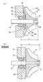
図2(a)は実施例1の過給装置の要部断面図であり、図2(b)は従来技術の過給装置の要部断面図である。
過給装置の要部断面図である(実施例2)。
過給装置の要部断面図である(実施例3)。
過給装置の要部断面図である(実施例4)。
以下において実施形態を、図面に基づいて詳細に説明する。
本開示を電動過給機に適用した実施例を説明する。なお、以下で開示する実施例は、一例を開示するものであって、本開示が実施例に限定されないことは言うまでもない。
(実施例1)
図1、図2に基づいて実施例1を説明する。車両走行用のエンジン1(燃料の燃焼により回転動力を発生する内燃機関:燃料の種類やエンジン形式を問わない)は、電動過給機2を搭載する。
(実施例1)
図1、図2に基づいて実施例1を説明する。車両走行用のエンジン1(燃料の燃焼により回転動力を発生する内燃機関:燃料の種類やエンジン形式を問わない)は、電動過給機2を搭載する。
エンジン1は、吸気をエンジン気筒内へ導く吸気通路3を備える。電動過給機2は、吸気通路3の途中に配置される遠心式の吸気コンプレッサ4と、この吸気コンプレッサ4を駆動する電動モータ5とを備える。吸気コンプレッサ4は、電動モータ5が発生する回転力により駆動されて吸気を加圧するコンプレッサホイール6と、吸気通路3の途中に介在され、コンプレッサホイール6を収容する渦巻形状のコンプレッサケーシング7とを備える。
電動モータ5は、電力を回転出力に変換する周知の電動機であり、具体的な型式は限定するものではないが、一例として三相かご型誘導電動機等が用いられる。この電動モータ5は、周知の制御装置10により通電制御される。具体的な一例として、制御装置10は、電源11(車載バッテリやオルタネータ等)から供給される直流電力を交流に変換するインバータ12と、このインバータ12の切替状態をコントロールすることで電動モータ5に与える電圧や周波数を任意に変更するECU13とを備える。このECU13は、エンジン1の燃料噴射制御を行うエンジンコントロールユニットであり、エンジン1の運転状態に応じてインバータ12を介して電動モータ5の回転数をコントロールすることで、エンジン1の運転状態に応じた過給圧を発生させる。
電動モータ5は、機械的な構造として、回転自在に支持されるシャフト14と、このシャフト14と一体に回転するロータと、このロータと協動してロータを回転駆動するステータと、ロータおよびステータを収容するハウジング15とを備える。
ハウジング15は、軸方向に離間した2つのベアリング16を備える。なお、図2では、コンプレッサホイール6に近い側のベアリング16のみを示す。ハウジング15によって支持されるベアリング16は、シャフト14を回転自在に支持するためのものであり、ボールベアリングなどの転がりベアリングであっても良いし、滑りによってシャフト14を支持するメタルベアリングであっても良い。
シャフト14には、ハウジング15の外部に突出する部分(以下、シャフト突出部)を備える。このシャフト突出部は、コンプレッサホイール6が組付けられ箇所であり、コンプレッサホイール6を結合するための雄ネジと段差が設けられている。雄ネジは、シャフト突出部の先端(図2(a)の右端部分)に設けられる。段差は、雄ネジよりハウジング15側(図2(a)の左側)に設けられるものであり、段差より雄ネジ側(図2(a)の右側)が小径に設けられる。なお、段差より図示左側のシャフト14を大径シャフトと称し、段差より図示右側のシャフト14を小径シャフトと称する。
コンプレッサホイール6は、金属の削り出し等により製造されるものであり(限定しない)、略円錐形状を呈するベース部17と、回転によって吸気を駆動する複数のコンプレッサブレード18とを備える。また、コンプレッサホイール6の中心部には、コンプレッサホイール6をシャフト14に取り付けるための貫通穴が形成されている。
貫通穴の途中には、段差と軸方向において圧接するホイール側段差が設けられており、ホイール側段差より表面側(図2(a)の右側)が小径に設けられている。なお、ホイール側段差より図示左側の貫通穴を大径穴と称し、ホイール側段差より図示右側の貫通穴を小径穴と称する。そして、シャフト14とコンプレッサホイール6の軸芯を一致させるべく、「大径シャフトと大径穴」または「小径シャフトと小径穴」の少なくとも一方が略同径に設けられる。
コンプレッサホイール6の表面側の中心部には、シャフト14の先端に螺合するナット21から締結力を受けるネジ座面22が設けられている。このネジ座面22は、軸方向に対して垂直な平面部であり、ベース部17の頂部に設けられる。そして、シャフト14のシャフト突出部にコンプレッサホイール6を組付け、シャフト14の先端の雄ネジにナット21を締結することで、コンプレッサホイール6がシャフト14に結合される。
電動過給機2は、過給装置の一例であり、上述したように、回転駆動されるシャフト14と、このシャフト14を回転自在に支持するベアリング16と、このベアリング16を支持するハウジング15と、ベアリング16よりシャフト14の自由端側に固定されるコンプレッサホイール6と、を備えて構成される。
また、電動過給機2は、ベアリング16よりコンプレッサホイール6側(図示右側)に配置したシール部23によって、シャフト14とハウジング15の間をシールする構造を採用する。即ち、ハウジング15とシャフト14の間にシール部23を配置し、コンプレッサホイール6の軸周りからベアリング16へ、ダスト等の異物が侵入するのを防いでいる。なお、シール部23は、リップシールやダストシールなど周知なものであり、構造等を限定するものではない。
従来技術では、図2(b)に示すように、ベアリング16とコンプレッサホイール6との間にシール部23を配置することにより、オーバーハングLが長くなってしまい、オーバーハング範囲の1次の共振周波数を高めることの阻害要因になっていた。これに対し、この実施例1の電動過給機2では、図2(a)に示すように、コンプレッサホイール6の裏面の中央部に、裏面の周囲に比較して表面側へ向かって窪む凹部24を設けて、この凹部24とシール部23とを軸方向にオーバーラップさせる構成を採用している。
凹部24の具体的な一例を説明する。ここで、コンプレッサホイール6の裏面のうち、凹部24より外径側の面を外周裏面25とする。また、凹部24のうちで、最も表面(図示右側)に近い面を底面26とし、凹部24のうちで、外周裏面25から底面26へ向かう面を環状壁27とする。
この実施例1の凹部24は、コンプレッサホイール6を裏面側から見た場合に丸穴形状の窪みに設けられる(限定しない)。具体的な一例として、底面26は軸方向に垂直平面に設けられており、環状壁27は円筒面に設けられる。
一方、シール部23の周囲を支持する箇所のハウジング15には、図2(a)に示すように、コンプレッサホイール6側(図示右側)に向かって膨出する凸部28が設けられており、この凸部28の内側にシール部23が配置される。即ち、この実施例1では、シール部23と凸部28が、コンプレッサホイール6の裏面に設けた凹部24と軸方向においてオーバーラップするように設けられている。なお、図面では、凸部28の形状を、図2(a)の右側に向かって縮径する円錐面に設けているが、もちろん限定するものでなない。
実施例1の効果について述べる。この実施例1の電動過給機2は、上述したように、コンプレッサホイール6の裏面に凹部24を設けて、凹部24とシール部23を軸方向においてオーバーラップさせる構成を採用する。これにより、コンプレッサホイール6とシール部23を軸方向にオーバーラップさせることができるため、図2(a)に示すように、オーバーハングLを短縮することができる。このように、オーバーハングLを短縮することにより、オーバーハング範囲における回転部品の1次の共振周波数を高めることができ、シャフト14およびコンプレッサホイール6の高回転化が可能になる。これによって、電動過給機2の過給圧を高めることができ、エンジン1の高出力化が可能になる。あるいは、電動過給機2の過給圧を従来技術と同等にする場合、電動過給機2の小型化が可能になる。
(実施例2)
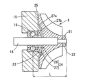
図3に基づいて実施例2を説明する。なお、以下の各実施例において上記実施例1と同一符号は、同一機能物を示すものである。上記の実施例1では、凹部24の環状壁27を円筒面に設ける例を示した。これに対し、この実施例2では、外周裏面25と環状壁27の境界部である角部27aと、環状壁27と底面26の境界部である隅部27bの両方を、底面26から外周裏面25(図示左方向)に向かって広がる断面が直線のテーパ面に設けたものである。なお、図3では、角部27aのテーパ面と隅部27bのテーパ面を連続して設ける例を示すが、角部27aのテーパ面と隅部27bのテーパ面が独立するもの(非連続の傾斜面)であっても良い。
(実施例2)
図3に基づいて実施例2を説明する。なお、以下の各実施例において上記実施例1と同一符号は、同一機能物を示すものである。上記の実施例1では、凹部24の環状壁27を円筒面に設ける例を示した。これに対し、この実施例2では、外周裏面25と環状壁27の境界部である角部27aと、環状壁27と底面26の境界部である隅部27bの両方を、底面26から外周裏面25(図示左方向)に向かって広がる断面が直線のテーパ面に設けたものである。なお、図3では、角部27aのテーパ面と隅部27bのテーパ面を連続して設ける例を示すが、角部27aのテーパ面と隅部27bのテーパ面が独立するもの(非連続の傾斜面)であっても良い。
このように、角部27aと隅部27bをテーパ面に設けることで、コンプレッサホイール6の裏面側において遠心力により生じる応力集中を緩和することができる。このため、凹部24の軸方向の深さを深く設けることが可能になる。その結果、凹部24とシール部23の軸方向におけるオーバーラップ量をさらに大きくすることが可能になり、オーバーハングLをさらに短縮することができる。
(実施例3)
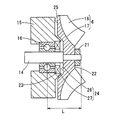
図4に基づいて実施例3を説明する。上記の実施例2では、角部27aと隅部27bを断面が直線のテーパ面(円錐面)に設ける例を示した。これに対し、この実施例3は、角部27aと隅部27bのそれぞれを、底面26側から外周裏面25方向へ向かって広がる曲面に設けたものである。なお、曲面は、曲率が一定のR面(円弧面)であっても良いし、曲率が一定でない断面が楕円や放物線等の曲面であっても良い。この実施例3を採用しても、上記実施例2と同様の効果を得ることができる。
(実施例4)
図5に基づいて実施例4を説明する。この実施例4は、コンプレッサブレード18の軸方向における表面側の先端部(図示右側の端)より、ネジ座面22を裏面側(図示左側)に近づけたものである。即ち、この実施例のコンプレッサホイール6は、ベース部17を偏平化し、凹部24の底面26とネジ座面22との距離を短くしたものである。
(実施例3)
図4に基づいて実施例3を説明する。上記の実施例2では、角部27aと隅部27bを断面が直線のテーパ面(円錐面)に設ける例を示した。これに対し、この実施例3は、角部27aと隅部27bのそれぞれを、底面26側から外周裏面25方向へ向かって広がる曲面に設けたものである。なお、曲面は、曲率が一定のR面(円弧面)であっても良いし、曲率が一定でない断面が楕円や放物線等の曲面であっても良い。この実施例3を採用しても、上記実施例2と同様の効果を得ることができる。
(実施例4)
図5に基づいて実施例4を説明する。この実施例4は、コンプレッサブレード18の軸方向における表面側の先端部(図示右側の端)より、ネジ座面22を裏面側(図示左側)に近づけたものである。即ち、この実施例のコンプレッサホイール6は、ベース部17を偏平化し、凹部24の底面26とネジ座面22との距離を短くしたものである。
このように、ネジ座面22を凹部24の底面26に近づけたことで、さらにオーバーハングLを短縮することが可能になり、電動過給機2の大幅な高回転化が可能になる。即ち、実施例4を採用することによって、電動過給機2の高過給圧化や小型化の効果を高めることができる。
産業上の利用可能性について述べる。上記の実施例では、本開示を電動過給機2に適用する例を示したが、エンジン1の排気圧によって吸気コンプレッサ4を駆動するターボチャージャに本開示を適用しても良い。なお、ターボチャージャに適用する場合、オーバーハングLを短縮することで、オーバーハング範囲における3次の共振周波数を高めることができる。
本開示は、実施例に準拠して記述されたが、本開示は当該実施例や構造に限定されるものではないと理解される。本開示は、様々な変形例や均等範囲内の変形をも包含する。加えて、様々な組み合わせや形態、さらには、それらに一要素のみ、それ以上、あるいはそれ以下、を含む他の組み合わせや形態をも、本開示の範疇や思想範囲に入るものである。
Claims (5)
- 回転駆動されるシャフト(14)と、
このシャフト(14)を回転自在に支持するベアリング(16)と、
このベアリング(16)を支持するハウジング(15)と、
前記ベアリング(16)より前記シャフト(14)の自由端側に固定されるコンプレッサホイール(6)と、
前記シャフト(14)と前記ハウジング(15)の間を、前記ベアリング(16)より前記コンプレッサホイール(6)側においてシールするシール部(23)と、
を具備する過給装置において、
前記コンプレッサホイール(6)のうち、前記ベアリング(16)に近い面を裏面、前記ベアリング(16)から遠い面を表面とし、前記シャフト(14)の中心軸が伸びる方向を軸方向とした場合、
前記コンプレッサホイール(6)の前記裏面に、前記裏面の周囲に比較して前記表面側へ向かって窪む凹部(24)を設けて、前記凹部(24)と前記シール部(23)を軸方向にてオーバーラップさせることを特徴とする過給装置。 - 請求項1に記載の過給装置において、
この過給装置は、前記コンプレッサホイール(6)を電動モータ(5)により駆動する電動過給機(2)であることを特徴とする過給装置。 - 請求項1または請求項2に記載の過給装置において、
前記裏面は、前記凹部(24)の周囲の外周裏面(25)を備え、
前記凹部(24)は、当該凹部(24)のうちで最も前記表面に近い底面(26)と、前記外周裏面(25)から前記底面(26)へ向かう環状壁(27)とを備え、
前記外周裏面(25)と前記環状壁(27)の境界部である角部(27a)と、前記環状壁(27)と前記底面(26)の境界部である隅部(27b)は、前記底面(26)から前記外周裏面(25)に向かって広がる断面が直線のテーパ面に設けられることを特徴とする過給装置。 - 請求項1または請求項2に記載の過給装置において、
前記裏面は、前記凹部(24)の周囲に外周裏面(25)を備え、
前記凹部(24)は、当該凹部(24)のうちで最も前記表面に近い底面(26)と、前記外周裏面(25)から前記底面(26)へ向かう環状壁(27)とを備え、
前記外周裏面(25)と前記環状壁(27)の境界部である角部(27a)と、前記環状壁(27)と前記底面(26)の境界部である隅部(27b)は、前記底面(26)側から前記外周裏面(25)方向へ向かって広がる曲面に設けられることを特徴とする過給装置。 - 請求項1または請求項2に記載の過給装置において、
前記コンプレッサホイール(6)の表面には、回転によって吸気を駆動する複数のコンプレッサブレード(18)の他に、前記シャフト(14)の先端に螺合するナット(21)から締結力を受けるネジ座面(22)が設けられ、
前記ネジ座面(22)は、前記コンプレッサブレード(18)の軸方向における表面側の先端部より、前記裏面側に設けられることを特徴とする過給装置。
Priority Applications (1)
| Application Number | Priority Date | Filing Date | Title |
|---|---|---|---|
| DE112016001380.9T DE112016001380T5 (de) | 2015-03-23 | 2016-03-21 | Aufladevorrichtung |
Applications Claiming Priority (2)
| Application Number | Priority Date | Filing Date | Title |
|---|---|---|---|
| JP2015060164A JP2016180337A (ja) | 2015-03-23 | 2015-03-23 | 過給装置 |
| JP2015-060164 | 2015-03-23 |
Publications (1)
| Publication Number | Publication Date |
|---|---|
| WO2016152139A1 true WO2016152139A1 (ja) | 2016-09-29 |
Family
ID=56977049
Family Applications (1)
| Application Number | Title | Priority Date | Filing Date |
|---|---|---|---|
| PCT/JP2016/001622 Ceased WO2016152139A1 (ja) | 2015-03-23 | 2016-03-21 | 過給装置 |
Country Status (3)
| Country | Link |
|---|---|
| JP (1) | JP2016180337A (ja) |
| DE (1) | DE112016001380T5 (ja) |
| WO (1) | WO2016152139A1 (ja) |
Cited By (1)
| Publication number | Priority date | Publication date | Assignee | Title |
|---|---|---|---|---|
| WO2018179144A1 (ja) * | 2017-03-29 | 2018-10-04 | 三菱重工業株式会社 | 電動過給機 |
Families Citing this family (3)
| Publication number | Priority date | Publication date | Assignee | Title |
|---|---|---|---|---|
| JP6899232B2 (ja) * | 2017-03-07 | 2021-07-07 | 三菱重工業株式会社 | 電動過給機 |
| WO2018230714A1 (ja) * | 2017-06-16 | 2018-12-20 | 株式会社Ihi | 車両過給機用frpインペラ |
| CN121511358A (zh) * | 2023-04-18 | 2026-02-10 | 皮尔伯格泵技术有限责任公司 | 电动气流泵 |
Citations (5)
| Publication number | Priority date | Publication date | Assignee | Title |
|---|---|---|---|---|
| JPS56138499A (en) * | 1980-04-01 | 1981-10-29 | Toyota Motor Corp | Compressor structure for turbocharger |
| JPS58113599A (ja) * | 1981-12-28 | 1983-07-06 | Hitachi Ltd | 遠心送風機 |
| JPH0233401A (ja) * | 1988-07-25 | 1990-02-02 | Isuzu Motors Ltd | 翼車軸の軸受構造 |
| JP2010096113A (ja) * | 2008-10-17 | 2010-04-30 | Ihi Corp | インペラ締結構造 |
| JP2011052580A (ja) * | 2009-09-01 | 2011-03-17 | Ihi Corp | ターボ機械 |
-
2015
- 2015-03-23 JP JP2015060164A patent/JP2016180337A/ja active Pending
-
2016
- 2016-03-21 WO PCT/JP2016/001622 patent/WO2016152139A1/ja not_active Ceased
- 2016-03-21 DE DE112016001380.9T patent/DE112016001380T5/de not_active Withdrawn
Patent Citations (5)
| Publication number | Priority date | Publication date | Assignee | Title |
|---|---|---|---|---|
| JPS56138499A (en) * | 1980-04-01 | 1981-10-29 | Toyota Motor Corp | Compressor structure for turbocharger |
| JPS58113599A (ja) * | 1981-12-28 | 1983-07-06 | Hitachi Ltd | 遠心送風機 |
| JPH0233401A (ja) * | 1988-07-25 | 1990-02-02 | Isuzu Motors Ltd | 翼車軸の軸受構造 |
| JP2010096113A (ja) * | 2008-10-17 | 2010-04-30 | Ihi Corp | インペラ締結構造 |
| JP2011052580A (ja) * | 2009-09-01 | 2011-03-17 | Ihi Corp | ターボ機械 |
Cited By (2)
| Publication number | Priority date | Publication date | Assignee | Title |
|---|---|---|---|---|
| WO2018179144A1 (ja) * | 2017-03-29 | 2018-10-04 | 三菱重工業株式会社 | 電動過給機 |
| JPWO2018179144A1 (ja) * | 2017-03-29 | 2019-07-18 | 三菱重工業株式会社 | 電動過給機 |
Also Published As
| Publication number | Publication date |
|---|---|
| DE112016001380T5 (de) | 2017-12-14 |
| JP2016180337A (ja) | 2016-10-13 |
Similar Documents
| Publication | Publication Date | Title |
|---|---|---|
| JP4671177B2 (ja) | 電動過給機 | |
| US7352077B2 (en) | Motor-driven supercharger | |
| CN107110011B (zh) | 涡轮增压器 | |
| US7834504B2 (en) | Motor rotor | |
| WO2016152139A1 (ja) | 過給装置 | |
| JP6639264B2 (ja) | コンプレッサインペラ固定用ナット、インペラ組立体及び過給機 | |
| JP2015108378A (ja) | 排気ガスターボ過給機のシャフト組立体 | |
| CN104246171A (zh) | 用于带有内部电动机的涡轮增压器的轴承系统 | |
| JP2007336737A (ja) | モータロータ及びその回転バランス修正方法 | |
| JP2007071165A (ja) | 電動過給機の軸受構造 | |
| JP6396512B2 (ja) | 過給機 | |
| KR102487166B1 (ko) | 모터의 레졸버 장착 구조 | |
| WO2016199821A1 (ja) | 回転機械 | |
| JP6333485B2 (ja) | インペラ組立体、過給機及びインペラ組立体の組立方法 | |
| US10727711B2 (en) | Motor rotor, supercharger, and method of manufacturing motor rotor | |
| JP2010200456A (ja) | モータロータ | |
| CN108292875A (zh) | 旋转电机 | |
| CN209539447U (zh) | 增压器 | |
| JP2012087661A (ja) | 電動ポンプユニット | |
| KR101542991B1 (ko) | 스러스트러너를 갖는 터보차저 | |
| WO2024224721A1 (ja) | 回転機械 | |
| CN205559616U (zh) | 双驱动压缩机 | |
| JP2005269756A (ja) | 回転電機 | |
| JP4306767B2 (ja) | 車両用交流発電機 | |
| CN121611640A (zh) | 一种冷却风叶和电机 |
Legal Events
| Date | Code | Title | Description |
|---|---|---|---|
| 121 | Ep: the epo has been informed by wipo that ep was designated in this application |
Ref document number: 16768046 Country of ref document: EP Kind code of ref document: A1 |
|
| WWE | Wipo information: entry into national phase |
Ref document number: 112016001380 Country of ref document: DE |
|
| 122 | Ep: pct application non-entry in european phase |
Ref document number: 16768046 Country of ref document: EP Kind code of ref document: A1 |