WO2016151870A1 - 圧力緩衝装置 - Google Patents
圧力緩衝装置 Download PDFInfo
- Publication number
- WO2016151870A1 WO2016151870A1 PCT/JP2015/060573 JP2015060573W WO2016151870A1 WO 2016151870 A1 WO2016151870 A1 WO 2016151870A1 JP 2015060573 W JP2015060573 W JP 2015060573W WO 2016151870 A1 WO2016151870 A1 WO 2016151870A1
- Authority
- WO
- WIPO (PCT)
- Prior art keywords
- cylinder
- oil
- rod
- seal
- rod member
- Prior art date
- Legal status (The legal status is an assumption and is not a legal conclusion. Google has not performed a legal analysis and makes no representation as to the accuracy of the status listed.)
- Ceased
Links
Images



Classifications
-
- F—MECHANICAL ENGINEERING; LIGHTING; HEATING; WEAPONS; BLASTING
- F16—ENGINEERING ELEMENTS AND UNITS; GENERAL MEASURES FOR PRODUCING AND MAINTAINING EFFECTIVE FUNCTIONING OF MACHINES OR INSTALLATIONS; THERMAL INSULATION IN GENERAL
- F16F—SPRINGS; SHOCK-ABSORBERS; MEANS FOR DAMPING VIBRATION
- F16F9/00—Springs, vibration-dampers, shock-absorbers, or similarly-constructed movement-dampers using a fluid or the equivalent as damping medium
- F16F9/32—Details
- F16F9/36—Special sealings, including sealings or guides for piston-rods
-
- F—MECHANICAL ENGINEERING; LIGHTING; HEATING; WEAPONS; BLASTING
- F16—ENGINEERING ELEMENTS AND UNITS; GENERAL MEASURES FOR PRODUCING AND MAINTAINING EFFECTIVE FUNCTIONING OF MACHINES OR INSTALLATIONS; THERMAL INSULATION IN GENERAL
- F16F—SPRINGS; SHOCK-ABSORBERS; MEANS FOR DAMPING VIBRATION
- F16F9/00—Springs, vibration-dampers, shock-absorbers, or similarly-constructed movement-dampers using a fluid or the equivalent as damping medium
- F16F9/10—Springs, vibration-dampers, shock-absorbers, or similarly-constructed movement-dampers using a fluid or the equivalent as damping medium using liquid only; using a fluid of which the nature is immaterial
- F16F9/14—Devices with one or more members, e.g. pistons, vanes, moving to and fro in chambers and using throttling effect
- F16F9/16—Devices with one or more members, e.g. pistons, vanes, moving to and fro in chambers and using throttling effect involving only straight-line movement of the effective parts
- F16F9/18—Devices with one or more members, e.g. pistons, vanes, moving to and fro in chambers and using throttling effect involving only straight-line movement of the effective parts with a closed cylinder and a piston separating two or more working spaces therein
-
- F—MECHANICAL ENGINEERING; LIGHTING; HEATING; WEAPONS; BLASTING
- F16—ENGINEERING ELEMENTS AND UNITS; GENERAL MEASURES FOR PRODUCING AND MAINTAINING EFFECTIVE FUNCTIONING OF MACHINES OR INSTALLATIONS; THERMAL INSULATION IN GENERAL
- F16F—SPRINGS; SHOCK-ABSORBERS; MEANS FOR DAMPING VIBRATION
- F16F9/00—Springs, vibration-dampers, shock-absorbers, or similarly-constructed movement-dampers using a fluid or the equivalent as damping medium
- F16F9/32—Details
- F16F9/3207—Constructional features
- F16F9/3235—Constructional features of cylinders
- F16F9/3242—Constructional features of cylinders of cylinder ends, e.g. caps
-
- F—MECHANICAL ENGINEERING; LIGHTING; HEATING; WEAPONS; BLASTING
- F16—ENGINEERING ELEMENTS AND UNITS; GENERAL MEASURES FOR PRODUCING AND MAINTAINING EFFECTIVE FUNCTIONING OF MACHINES OR INSTALLATIONS; THERMAL INSULATION IN GENERAL
- F16F—SPRINGS; SHOCK-ABSORBERS; MEANS FOR DAMPING VIBRATION
- F16F9/00—Springs, vibration-dampers, shock-absorbers, or similarly-constructed movement-dampers using a fluid or the equivalent as damping medium
- F16F9/32—Details
- F16F9/3207—Constructional features
- F16F9/3235—Constructional features of cylinders
- F16F9/3257—Constructional features of cylinders in twin-tube type devices
-
- F—MECHANICAL ENGINEERING; LIGHTING; HEATING; WEAPONS; BLASTING
- F16—ENGINEERING ELEMENTS AND UNITS; GENERAL MEASURES FOR PRODUCING AND MAINTAINING EFFECTIVE FUNCTIONING OF MACHINES OR INSTALLATIONS; THERMAL INSULATION IN GENERAL
- F16F—SPRINGS; SHOCK-ABSORBERS; MEANS FOR DAMPING VIBRATION
- F16F9/00—Springs, vibration-dampers, shock-absorbers, or similarly-constructed movement-dampers using a fluid or the equivalent as damping medium
- F16F9/32—Details
- F16F9/3278—Details for lubrication
-
- B—PERFORMING OPERATIONS; TRANSPORTING
- B60—VEHICLES IN GENERAL
- B60G—VEHICLE SUSPENSION ARRANGEMENTS
- B60G13/00—Resilient suspensions characterised by arrangement, location or type of vibration dampers
- B60G13/02—Resilient suspensions characterised by arrangement, location or type of vibration dampers having dampers dissipating energy, e.g. frictionally
- B60G13/06—Resilient suspensions characterised by arrangement, location or type of vibration dampers having dampers dissipating energy, e.g. frictionally of fluid type
- B60G13/08—Resilient suspensions characterised by arrangement, location or type of vibration dampers having dampers dissipating energy, e.g. frictionally of fluid type hydraulic
-
- B—PERFORMING OPERATIONS; TRANSPORTING
- B60—VEHICLES IN GENERAL
- B60G—VEHICLE SUSPENSION ARRANGEMENTS
- B60G2300/00—Indexing codes relating to the type of vehicle
- B60G2300/12—Cycles; Motorcycles
- B60G2300/124—Quads
-
- F—MECHANICAL ENGINEERING; LIGHTING; HEATING; WEAPONS; BLASTING
- F16—ENGINEERING ELEMENTS AND UNITS; GENERAL MEASURES FOR PRODUCING AND MAINTAINING EFFECTIVE FUNCTIONING OF MACHINES OR INSTALLATIONS; THERMAL INSULATION IN GENERAL
- F16F—SPRINGS; SHOCK-ABSORBERS; MEANS FOR DAMPING VIBRATION
- F16F2230/00—Purpose; Design features
- F16F2230/30—Sealing arrangements
Definitions
- the present invention relates to a pressure buffering device.
- Suspension devices for vehicles such as automobiles are equipped with a pressure buffering device that uses a damping force generator to appropriately mitigate vibrations transmitted from the road surface to the vehicle body during traveling and improve riding comfort and handling stability.
- the pressure buffer device is provided with, for example, a piston that is movably provided in the cylinder and partitions the inside of the cylinder, and a rod member that is connected to the piston, and resists the flow of liquid that occurs as the piston moves.
- a damping force is generated by applying the pressure (see, for example, Patent Document 1).
- a seal member that suppresses the outflow of the liquid in the cylinder is provided outside the rod member. Then, by supplying a part of the liquid in the cylinder to the seal member, for example, the liquid tightness between the seal member and the rod member may be increased. In such a case, it is preferable that the amount of liquid supplied from the cylinder to the seal member is an appropriate amount.
- An object of the present invention is to supply an appropriate amount of liquid to a seal member in a pressure buffering device.
- the present invention includes a cylinder for storing a liquid, and is inserted into the cylinder toward one side of the cylinder, and protrudes outside the cylinder on the other side of the cylinder.
- a rod member movably provided with respect to the cylinder, a through-hole through which the rod member penetrates, a covering member that covers the other side of the cylinder, the other side of the cylinder, and the rod member
- a seal member provided on the outer side in the radial direction, a flow path portion that forms a flow path of the liquid from the cylinder toward the seal member, and a throttle portion that restricts the flow of the liquid flowing through the flow path portion; Is a pressure buffering device.
- an appropriate amount of liquid can be supplied to the seal member in the pressure buffering device.
- FIG. 1 is an overall configuration diagram of a hydraulic shock absorber according to Embodiment 1.
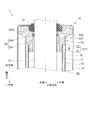
- FIG. (A) is an enlarged view in the edge part of the other side of the cylinder part of Embodiment 1
- (B) is a detailed view of a rod guide.
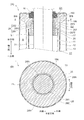
- (A) is a cross-sectional view taken along line IIIA-IIIA shown in FIG. 2
- (B) is a cross-sectional view taken along line IIIB-IIIB shown in FIG.
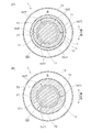
- FIG. (A) is an enlarged view in the edge part of the other side of the cylinder part of Embodiment 2.
- FIG. (B) is a sectional view of IVB-IVB shown in (A).
- FIG. 6 is an enlarged view of an end portion on the other side of the cylinder portion of the third embodiment. 6 is an enlarged view of an end portion on the other side of a cylinder portion according to Embodiment 4.
- FIG. 1 is an overall configuration diagram of a hydraulic shock absorber 1 according to a first embodiment.
- the lower side in the drawing in the axial direction of the hydraulic shock absorber 1 shown in FIG. 1 is referred to as “one side”, and the upper side in the drawing is referred to as “the other side”.
- the center side in the radial direction of the hydraulic shock absorber 1 is referred to as “inside”, and the outside in the radial direction is referred to as “outside”.
- the hydraulic shock absorber 1 (pressure shock absorber) is inserted into the cylinder portion 10 with the cylinder portion 10 and the other side facing one side of the cylinder portion 10, and the other side of the cylinder portion 10.
- the rod part 20 that protrudes outside the cylinder part 10 on the side and is provided so as to be movable in the axial direction relative to the cylinder part 10, the piston part 30 provided at one end of the rod part 20, and the cylinder part 10
- the outer valve part 40 provided on the outer side in the radial direction of the cylinder part 10 and the bottom valve part 50 disposed at one end of the cylinder part 10 are provided.
- the hydraulic shock absorber 1 is provided between a vehicle body and an axle in, for example, a four-wheel automobile or a two-wheel automobile, and attenuates the amplitude motion of the rod portion 20 with respect to the cylinder portion 10.
- the cylinder portion 10 includes a first cylinder 11, a second cylinder 12 provided outside the first cylinder 11, a third cylinder 13 provided further outside the second cylinder 12, and an axial direction of the third cylinder 13.
- a bottom 14 provided at one end, a rod guide 15 provided outside the rod 20 in the radial direction, an oil seal 16 provided inside the rod guide 15 on the other side, and a rod guide 15 It has a guide bush 17 provided on one side inside and a resin ring 18 provided on the other side of the guide bush 17.
- the rod portion 20 includes a rod member 21 formed to extend in the axial direction, a one-side attachment portion 21 a provided at one end of the rod member 21, and an end on the other side of the rod member 21. It has the other side attachment part 21b provided in a part.
- the one side attachment portion 21 a of the rod member 21 holds the piston portion 30.
- a connecting member (not shown) for connecting the hydraulic shock absorber 1 to a vehicle body such as an automobile is attached to the other side attachment portion 21b of the rod member 21.
- the piston part 30 is provided in the first cylinder 11 so as to be slidable in the axial direction.
- the piston portion 30 provided in the first cylinder 11 divides the space in the first cylinder 11 into a first oil chamber Y1 and a second oil chamber Y2. Further, the piston part 30 has a path through which oil flows between the first oil chamber Y1 and the second oil chamber Y2.
- the outer valve portion 40 is provided on the side portion of the third cylinder 13 in this embodiment. More specifically, the outer valve portion 40 communicates with the communication path L and the reservoir chamber R. And resistance is provided with respect to the oil which flows between the communication path L and the reservoir chamber R, and a damping force is generated. In the present embodiment, the outer valve portion 40 can change the flow path cross-sectional area through which oil flows. That is, it is possible to change the damping force to be generated in the outer valve portion 40. In the outer valve portion 40, a solenoid can be used to change the flow path cross-sectional area.
- the bottom valve unit 50 is attached to one end of the first cylinder 11 and the second cylinder 12.
- the bottom valve unit 50 separates the first oil chamber Y1 and the reservoir chamber R from each other. Further, the bottom valve unit 50 has an oil passage that connects the first oil chamber Y1 and the reservoir chamber R.
- a hydraulic shock absorber 1 pressure shock absorber
- Embodiment 1 includes a first cylinder 11 (cylinder) that contains oil (liquid) and a first cylinder 11 toward one side of the first cylinder 11.
- a rod member 21 (rod member) which is inserted inside the cylinder 11 and protrudes outside the first cylinder 11 on the other side of the first cylinder 11 so as to be movable with respect to the first cylinder 11;
- a rod guide 15 (cover member) that has a through hole through which the member 21 passes and covers the other side of the first cylinder 11, and is provided on the other side of the first cylinder 11 and outside the rod member 21 in the radial direction.
- Oil seal 16 (seal member), groove portion 157T (flow passage portion) that forms a flow passage of oil from the first cylinder 11 toward the oil seal 16 side, and the flow of oil flowing through the groove portion 157T And a small diameter portion T2 (throttle portion) squeezing.
- these configurations will be described in detail.
- FIG. 2A is an enlarged view of the other end portion of the cylinder portion 10 according to the first embodiment
- FIG. 2B is a detailed view of the rod guide 15.
- 3A is a cross-sectional view taken along line IIIA-IIIA shown in FIG. 2
- FIG. 3B is a cross-sectional view taken along line IIIB-IIIB shown in FIG.
- the first cylinder 11 is a cylindrical member. Oil is accommodated inside the first cylinder 11.
- a part of one side of the rod member 21 and the piston part 30 are movably disposed inside the first cylinder 11.
- the second cylinder 12 is a cylindrical member.
- the second cylinder 12 is provided outside the first cylinder 11 and inside the third cylinder 13.
- the second cylinder 12 forms a communication path L through which oil flows between the second cylinder 12 and the first cylinder 11.
- the third cylinder 13 is a cylindrical member.
- a reservoir chamber R is formed between the third cylinder 13 and the second cylinder 12.
- the bottom 14 closes one end of the third cylinder 13.
- the bottom portion 14 supports the bottom valve portion 50.
- the bottom portion 14 also functions as a member that supports the first cylinder 11 and the second cylinder 12 via the bottom valve portion 50.
- the rod guide 15 has a through hole extending in the axial direction on the inner side in the radial direction, and is formed in a substantially cylindrical shape.
- the rod guide 15 has the rod member 21 penetrated inside in the radial direction, and guides the movement of the rod member 21.
- a metal etc. can be used for the material of the rod guide 15 of this embodiment.
- the rod guide 15 of the present embodiment includes a first outer diameter portion 151 formed on the other side in the axial direction and a second outer portion formed on one side of the first outer diameter portion 151 on the outer side in the radial direction. It has a diameter portion 152 and a third outer diameter portion 153 formed on one side of the second outer diameter portion 152. Further, the rod guide 15 includes a seal holding part 154 formed on the other side in the axial direction on the inner side in the radial direction, a rod facing part 155 formed on one side of the seal holding part 154, and a rod facing part 155. It has a ring holding part 156 formed on one side and a bush holding part 157 formed on one side of the ring holding part 156.
- the outer diameter of the first outer diameter portion 151 is formed to be equal to the inner diameter of the third cylinder 13.
- the rod guide 15 is fitted into the third cylinder 13 at the first outer diameter portion 151.
- the outer diameter of the second outer diameter portion 152 is formed to be equal to the inner diameter of the second cylinder 12.
- the rod guide 15 is fitted into the second cylinder 12 at the second outer diameter portion 152.
- the outer diameter of the third outer diameter portion 153 is formed to be equal to the inner diameter of the first cylinder 11.
- the rod guide 15 is fitted into the first cylinder 11 at the third outer diameter portion 153.
- the third outer diameter portion 153 has an outer circumferential groove 153T that extends radially outward and extends in the axial direction.
- the outer peripheral groove 153 ⁇ / b> T forms a flow path through which oil flows between the first cylinder 11.
- the outer peripheral groove 153T connects the inside of the first cylinder 11 (second oil chamber Y2) and the outside of the first cylinder 11 (communication path L).
- the seal holding portion 154 is formed as an annular groove along the circumferential direction of the rod guide 15.
- the seal holding part 154 holds the oil seal 16 on the inner side in the radial direction.
- the inner diameter of the rod facing portion 155 is formed larger than the outer diameter of the rod member 21. Therefore, in the present embodiment, the first gap G ⁇ b> 1 is formed between the rod facing portion 155 and the rod member 21.
- the rod facing portion 155 has a facing portion flow path 155R on one side.
- the facing portion flow path 155R is formed by a notch formed in the radial direction.
- the opposing part flow path 155R enables the flow of oil between the first gap G1 and a groove part 157T described later, regardless of the position of the resin ring 18 in the axial direction.
- the inner diameter of the ring holding part 156 is formed larger than the outer diameter of the resin ring 18. Therefore, in the present embodiment, the second gap G ⁇ b> 2 is formed between the ring holding part 156 and the resin ring 18. Further, the axial width of the ring holding portion 156 is formed larger than the axial width of the resin ring 18. In the present embodiment, the resin ring 18 is held in the ring holding portion 156 in a state in which the resin ring 18 is movable in the axial direction.
- the inner diameter of the bush holding portion 157 is formed to be equal to the outer diameter of the guide bush 17 except for a portion where a groove portion 157T described later is formed.
- the bush holding portion 157 holds the guide bush 17 inside in the radial direction.
- the bush holding portion 157 has a groove portion 157T formed to extend in the axial direction.
- the groove portion 157T communicates with the inside of the first cylinder 11 (second oil chamber Y2) on one side, and communicates with the ring holding portion 156 (second gap G2) on the other side.
- the groove portion 157T forms an oil path from the first cylinder 11 toward the oil seal 16.
- the groove portion 157T has a large diameter portion T1 formed on one side and a small diameter portion T2 formed on the other side of the large diameter portion T1.
- a plurality of groove portions 157T (three in this embodiment) are provided.
- the plurality of groove portions 157T are arranged at substantially equal intervals in the circumferential direction of the rod guide 15.
- the oil passage cross-sectional area in the small-diameter portion T2 is set smaller than the oil passage cross-sectional area in the large-diameter portion T1.
- the cross-sectional area of the flow path in the large-diameter portion T1 is set so that the oil in the second oil chamber Y2 can be easily introduced.
- the small-diameter portion T2 forms a portion having a channel cross-sectional area smaller than the oil channel cross-sectional area on the upstream side (in this embodiment, the large-diameter portion T1 side) in the oil flow direction.
- the small diameter part T2 acts so as to restrict the flow of oil.
- the flow path cross-sectional area in the small diameter portion T2 is set so that an appropriate amount of oil is directed from the large diameter portion T1 to the oil seal 16.
- the groove portion 157T (flow path portion) serving as a path for supplying oil (liquid) from the inside of the first cylinder 11 (cylinder) toward the oil seal 16 (seal member) is a rod guide. 15 (covering member). Furthermore, a small diameter portion T2 (throttle portion) that restricts the flow of oil flowing through the groove portion 157T is formed in the rod guide 15. That is, the small diameter portion T2 (throttle portion) is formed between the rod guide 15 and the guide bush 17 (bearing member).
- the oil flow path from the first cylinder 11 toward the oil seal 16 is not limited to the groove 157T.
- oil can be introduced from the first cylinder 11, and an annular groove formed in the circumferential direction of the rod guide 15 may be used.
- a structure corresponding to the small-diameter portion T2 (throttle portion) on the other side (oil seal 16 side) may be provided so that the oil flow passage cross-sectional area is small.
- the oil seal 16 is a member whose general shape is formed in a substantially cylindrical shape.
- the oil seal 16 is attached to a seal holding portion 154 formed at the other end of the rod guide 15. The oil seal 16 is pressed against the rod guide 15 by the end of the third cylinder 13 on the other side.
- the guide bush 17 is a member formed in a substantially cylindrical shape.
- the guide bush 17 (bearing member) is provided inside the rod guide 15 (cover member) in the radial direction.
- the guide bush 17 supports the rod member 21 so as to be movable in the axial direction.
- the inner diameter of the guide bush 17 is set larger than the outer diameter of the rod member 21. Accordingly, a third gap G3 is formed between the guide bush 17 and the rod member 21.
- oil can flow into the third gap G3 of the present embodiment.
- a metal such as iron can be used as the material of the guide bush 17.
- the inner periphery of the guide bush 17 can be subjected to a surface treatment with a fluororesin such as Teflon (registered trademark).
- the resin ring 18 is a member formed in an annular shape.
- a resin material such as a fluororesin such as Teflon (registered trademark) can be used.
- Teflon registered trademark
- the resin ring 18 is press-fitted to the outside of the rod member 21 in the radial direction.
- the inner diameter of the resin ring 18 is slightly larger than the outer diameter of the rod member 21.
- the hydraulic shock absorber 1 is provided with the resin ring 18, but it is not always necessary and the resin ring 18 may not be provided.
- the width of the resin ring 18 (the length of the cross section from the inside to the outside in the radial direction) is formed larger than the third gap G3 between the guide bush 17 and the rod member 21.
- the resin ring 18 of the present embodiment restricts the oil in the first cylinder 11 from passing through the third gap G3 between the guide bush 17 and the rod member 21 toward the other side in the axial direction.
- the amount of oil flowing through the third gap G3 between the guide bush 17 and the rod member 21 is adjusted by the interval of the third gap G3 itself and the resin ring 18.
- the amount of oil in the third gap G3 between the guide bush 17 and the rod member 21 is directly related to the axial movement operation of the rod member 21 in the hydraulic shock absorber 1, for example. That is, the amount of oil in the third gap G3 affects the damping force characteristic in the hydraulic shock absorber 1. Therefore, in the present embodiment, regarding the control of the oil supply to the oil seal 16, between the guide bush 17 and the rod guide 15, which is a different location from the third gap G3 between the guide bush 17 and the rod member 21, This is realized by the groove 157T to be formed.
- the oil supply path to the oil seal 16 and the oil path in the third gap G3 between the guide bush 17 and the rod member 21 are provided separately. Yes.
- the flow of oil from the first cylinder 11 between the guide bush 17 and the rod guide 15 to the oil seal 16 may be narrowed, and the present invention is not limited to the above example.
- the shape of the large-diameter portion T1 of the groove portion 157T is not formed by the above-described groove extending in the axial direction, and may be an annular groove formed in the circumferential direction.
- the guide bush 17 may be formed with a groove or the like having the same function as the above-described groove portion 157T (small diameter portion T2). Further, the rod guide 15 and the guide bush 17 are configured separately, and another member having the same function as the groove portion 157T (the large diameter portion T1 and the small diameter portion T2) described above is provided between the rod guide 15 and the guide bush 17. You may make it attach to. That is, the small diameter portion T2 (throttle portion) may be formed between the rod guide 15 (cover member) and the guide bush 17 (bearing member).
- an oil opening or the like (flow path) having the same function as that of the groove portion 157T (large diameter portion T1, small diameter portion T2) described above is formed only in the rod guide 15 but not between the guide bush 17 and the rod guide 15. May be. That is, the small diameter portion T2 (throttle portion) that restricts the flow of oil flowing through the groove portion 157T (flow path portion) may be formed in the rod guide 15.
- FIG. 4A is an enlarged view of the other end portion of the cylinder portion 10 according to the second embodiment.
- FIG. 4B is a cross-sectional view taken along the line IVB-IVB shown in FIG.
- the same members and the like as those described in the first embodiment are denoted by the same reference numerals, and detailed description thereof is omitted.
- the hydraulic shock absorber 1 (pressure shock absorber) of the second embodiment includes a first cylinder 11 (cylinder) that stores oil (liquid), and a first cylinder. 11 is inserted into the inside of the first cylinder 11 toward one side of the rod 11, protrudes outside the first cylinder 11 on the other side of the first cylinder 11, and is provided so as to be movable with respect to the first cylinder 11.
- a rod guide 25 that has a member 21 (rod member), a through-hole through which the rod member 21 passes, covers the other side of the first cylinder 11, and a rod member that is the other side of the first cylinder 11 21, an oil seal 16 (seal member) provided on the outer side in the radial direction, a groove portion 257T (flow channel portion) that forms an oil flow path from the inside of the first cylinder 11 toward the oil seal 16 side, and a groove portion 25.
- a notch 28N aperture portion of the resin ring 28 to narrow the flow of oil through the T.
- the notch portion 28N is provided in the resin ring 28.
- the notch portion 28N is not limited to the resin ring, and the rod member 21 (outside in the radial direction of the resin ring 28) is disposed at a position opposite to the resin ring 28.
- the cutout portion 28N may be formed. Further, the cutout portion 28N may be formed by both the resin ring 28 and the rod member 21.
- the hydraulic shock absorber 1 of the second embodiment is different from the rod guide 15 and the resin ring 18 of the first embodiment in the configuration of the rod guide 25 and the resin ring 28. Below, it demonstrates centering around a different point about the rod guide 25 and the resin ring 28. FIG.
- the rod guide 25 of the second embodiment has a bush holding portion 257 that holds the guide bush 17. Further, the bush holding portion 257 has a groove portion 257T formed extending in the axial direction. A plurality (three in this embodiment) of the groove portions 257T are provided. The plurality of groove portions 257T are arranged at substantially equal intervals in the circumferential direction of the rod guide 25.
- the groove portion 257T communicates with the inside of the first cylinder 11 (second oil chamber Y2) on one side, and communicates with the ring holding portion 156 (second gap G2) on the other side.
- the groove portion 257T has an oil flow path cross-sectional area set so that the oil in the first cylinder 11 can be easily introduced as the rod member 21 moves.
- the resin ring 28 (annular member) is a member having an annular shape.
- the resin ring 28 is provided outside the rod member 21 in the radial direction.
- the resin ring 28 is disposed on the inner side of the first cylinder 11 (one side in the axial direction) than the oil seal 16 (seal member).
- the inner diameter of the resin ring 28 is set to be equal to the outer diameter of the rod member 21.
- the outer diameter of the resin ring 28 is set to be equal to the inner diameter of the ring holding portion 156.
- the cross-sectional shape of the resin ring 28 of the present embodiment is formed in a V shape.
- the resin ring 28 includes a contact portion 281 provided on the inner side in the radial direction and a deforming portion 282 provided on the outer side in the radial direction.
- the contact portion 281 forms a portion that contacts the rod member 21.
- the deforming portion 282 forms a portion that comes into contact with the ring holding portion 156.
- transformation part 282 is comprised so that a deformation
- the resin ring 28 is attached so that the opening 28H formed by the contact portion 281 and the deformation portion 282 faces one side where the groove portion 257T is formed.
- the resin ring 28 (annular member) has the notch part 28N (throttle part) formed in the radial direction outer side.
- a plurality (three in this embodiment) of the notches 28N are provided.
- the plurality of notches 28N are arranged at equal intervals in the circumferential direction of the resin ring 28.
- the notch 28N of the resin ring 28 communicates with the groove portion 257T on one side, and communicates with the first gap G1 in the rod facing portion 155 on the other side.
- the cutout portion 28N is formed to have a smaller channel cross-sectional area than the groove portion 257T.
- the notch 28N is provided on the oil flow path from the first cylinder 11 toward the oil seal 16.
- the oil in the first cylinder 11 flows into the groove portion 257T as the rod member 21 moves.
- the oil flow in the groove portion 257T is throttled by the notch portion 28N.
- the oil squeezed by the notch 28N is supplied from the inside of the first cylinder 11 toward the oil seal 16.
- an appropriate amount of oil can be supplied from the first cylinder 11 toward the oil seal 16.
- the embodiment is not limited to the above example as long as the oil flow in the groove portion 257T can be reduced.
- a notch may be formed inside the resin ring 28 in the radial direction.
- a through hole may be formed in the resin ring 28.
- FIG. 5 is an enlarged view of the other end portion of the cylinder portion 10 according to the third embodiment.
- the same members and the like as those described in the other embodiments are denoted by the same reference numerals, and detailed description thereof is omitted.
- the hydraulic shock absorber 1 pressure shock absorber
- the hydraulic shock absorber 1 includes a first cylinder 11 (cylinder) that contains oil (liquid) and a first cylinder 11 toward one side of the first cylinder 11.
- a rod member 21 (rod member) which is inserted inside the cylinder 11 and protrudes outside the first cylinder 11 on the other side of the first cylinder 11 so as to be movable with respect to the first cylinder 11;
- a rod guide 15 (cover member) that has a through hole through which the member 21 passes and covers the other side of the first cylinder 11, and is provided on the other side of the first cylinder 11 and outside the rod member 21 in the radial direction.
- Oil seal 16 (seal member), groove portion 157T (flow passage portion) that forms a flow passage of oil from the first cylinder 11 toward the oil seal 16 side, and the flow of oil flowing through the groove portion 157T And a notch 28N (aperture portion) of the small diameter portion T2 and the resin ring 28 squeeze.
- the hydraulic shock absorber 1 according to the third embodiment includes the rod guide 15 according to the first embodiment and the resin ring 28 according to the second embodiment. Also in the hydraulic shock absorber 1 of the third embodiment configured as described above, with the movement of the rod member 21, the oil flow from the first cylinder 11 toward the oil seal 16 is caused to flow into the groove portion 157T of the rod guide 15 and The resin ring 28 is squeezed by the notch 28N. In the hydraulic shock absorber 1 according to the third embodiment, an appropriate amount of oil can be supplied from the first cylinder 11 toward the oil seal 16.
- FIG. 6 is an enlarged view of the other end portion of the cylinder portion 10 according to the fourth embodiment.
- symbol is attached
- the hydraulic shock absorber 1 according to the fourth embodiment will be described. As illustrated in FIG. 6, the hydraulic shock absorber 1 (pressure shock absorber) according to the fourth embodiment includes a first cylinder 11 (cylinder) that stores oil (liquid) and a first cylinder 11 toward one side of the first cylinder 11.
- a rod member 21 (rod member) which is inserted inside the cylinder 11 and protrudes outside the first cylinder 11 on the other side of the first cylinder 11 so as to be movable with respect to the first cylinder 11;
- a rod guide 15 (cover member) that has a through hole through which the member 21 passes and covers the other side of the first cylinder 11, and is provided on the other side of the first cylinder 11 and outside the rod member 21 in the radial direction.
- the basic configuration of the hydraulic shock absorber 1 according to the fourth embodiment is the same as that of the hydraulic shock absorber 1 according to the third embodiment.
- the mounting direction of the resin ring 28 is different from that in the third embodiment.
- the resin ring 28 of the fourth embodiment does not have the notch portion 28N as an essential component.
- Embodiment 4 it attaches so that the direction of the opening 28H formed of the contact part 281 and the deformation
- the resin ring 28 can exhibit the action of the check valve. That is, the resin ring 28 is deformed such that the deformable portion 282 falls toward the other side. On the other hand, the resin ring 28 is less likely to be deformed by the deformable portion 282 toward one side.
- the deforming portion 282 (allowable restricting portion) of the resin ring 28 according to the present embodiment allows the oil flow from the first cylinder 11 toward the oil seal 16. Further, the resin ring 28 restricts the flow of oil from the oil seal 16 side toward the first cylinder 11 side.
- the rod guide 15 (25) and the guide bush 17 are described by using different members.
- the present invention is not limited to this mode.
- the rod guide 15 (25) itself may be configured to have the function of the guide bush 17.
- the rod guide 15 (25) and the guide bush 17 are integrally regarded as a single “cover member”. Then, the function of the groove portion 157T described above may be provided in this “cover member”.
- the rod facing portion 155 may have a flow passage cross-sectional area smaller than other portions, and a throttle portion that restricts the flow of oil toward the oil seal 16 may be formed. . Then, an appropriate amount of oil may be supplied from the first cylinder 11 toward the oil seal 16 by restricting the oil flow in the rod facing portion 155.
- the configuration of the oil seal 16 is not limited to the first to fourth embodiments. Any other configuration may be used as long as the member is provided on the other side of the first cylinder 11 and outside the rod member 21 in the radial direction and suppresses the outflow of oil.
- the hydraulic shock absorber 1 having a so-called triple pipe structure having the first cylinder 11, the second cylinder 12, and the third cylinder 13 has been described as an example.
- the present invention may be applied to a so-called double-pipe hydraulic shock absorber 1 having a first cylinder and a second cylinder 12 provided outside the first cylinder 11.
- SYMBOLS 1 Hydraulic shock absorber (an example of a pressure shock absorber), 11 ... 1st cylinder (an example of a cylinder), 12 ... 2nd cylinder, 13 ... 3rd cylinder, 15 (25) ... Rod guide (an example of a covering member), DESCRIPTION OF SYMBOLS 16 ... Oil seal (an example of a sealing member), 17 ... Guide bush (an example of a bearing member), 18 (28) ... Resin ring (an example of an annular member), 21 ... Rod member (an example of a rod member), 28N ... Notch Part (example of throttle part), 157T ... groove part (example of flow path part), T1 ... large diameter part, T2 ... small diameter part (example of throttle part), 282 ... deformation part (example of allowable restriction part)
Landscapes
- Engineering & Computer Science (AREA)
- General Engineering & Computer Science (AREA)
- Mechanical Engineering (AREA)
- Fluid-Damping Devices (AREA)
- Sealing Devices (AREA)
Abstract
油圧緩衝装置1は、オイルを収容する第1シリンダ11と、第1シリンダ11の一方側に向けて第1シリンダ11の内側に挿入されるとともに、第1シリンダ11の他方側にて第1シリンダ11の外側に突出し、第1シリンダ11に対して移動可能に設けられるロッド部材21と、ロッド部材21が貫通する貫通孔を有し、第1シリンダ11の他方側を覆うロッドガイド15と、第1シリンダ11の他方側であってロッド部材21の半径方向の外側に設けられるオイルシール16と、第1シリンダ11内からオイルシール16側に向かうオイルの流路を形成する溝部157Tと、溝部157Tを流れるオイルの流れを絞る小径部T2とを備える。これにより、圧力緩衝装置において、シール部材に対して適量の液体を供給する。
Description
本発明は、圧力緩衝装置に関する。
自動車等の車両の懸架装置は、走行中に路面から車体へ伝達される振動を適切に緩和して、乗心地や操縦安定性を向上させるために減衰力発生器を用いた圧力緩衝装置を備えている。そして、圧力緩衝装置には、例えばシリンダ内に移動可能に設けられてシリンダ内を区画するピストンと、ピストンに接続するロッド部材とが設けられ、ピストンの移動に伴って生じる液体の流れに抵抗を与えることで減衰力を発生させる(例えば、特許文献1参照)。
ところで、ロッド部材の外側には、シリンダ内の液体の流出を抑制するシール部材が設けられている。そして、シリンダ内の液体の一部をシール部材に供給することで、例えばシール部材とロッド部材との間における液密性を高めようとする場合がある。このような場合において、シリンダ内からシール部材への液体の供給量が適量であることが好ましい。
本発明は、圧力緩衝装置において、シール部材に対して適量の液体を供給することを目的とする。
かかる目的のもと、本発明は、液体を収容するシリンダと、前記シリンダの一方側に向けて前記シリンダの内側に挿入されるとともに、前記シリンダの他方側にて前記シリンダの外側に突出し、前記シリンダに対して移動可能に設けられるロッド部材と、前記ロッド部材が貫通する貫通孔を有し、前記シリンダの前記他方側を覆う覆い部材と、前記シリンダの前記他方側であって前記ロッド部材の半径方向の外側に設けられるシール部材と、前記シリンダ内から前記シール部材側に向かう前記液体の流路を形成する流路部と、前記流路部を流れる前記液体の流れを絞る絞り部と、を備える圧力緩衝装置である。
このような構成とすることにより、流路部を流れる液体の流れを絞る絞り部によって、シール部材に対して適量の液体を供給することができる。
このような構成とすることにより、流路部を流れる液体の流れを絞る絞り部によって、シール部材に対して適量の液体を供給することができる。
本発明によれば、圧力緩衝装置において、シール部材に対して適量の液体を供給することが可能になる。
以下、添付図面を参照して、本発明の実施の形態について詳細に説明する。
-実施形態1-
図1は、実施形態1の油圧緩衝装置1の全体構成図である。
なお、以下の説明においては、図1に示す油圧緩衝装置1の軸方向における図中下側を「一方側」と称し、図中上側を「他方側」と称する。また、油圧緩衝装置1の半径方向の中心側を「内側」、半径方向の外側を「外側」と称する。
-実施形態1-
図1は、実施形態1の油圧緩衝装置1の全体構成図である。
なお、以下の説明においては、図1に示す油圧緩衝装置1の軸方向における図中下側を「一方側」と称し、図中上側を「他方側」と称する。また、油圧緩衝装置1の半径方向の中心側を「内側」、半径方向の外側を「外側」と称する。
<油圧緩衝装置1の構成・機能>
図1に示すように、油圧緩衝装置1(圧力緩衝装置)は、シリンダ部10と、他方側がシリンダ部10の一方側に向けてシリンダ部10の内部に挿入されるとともに、シリンダ部10の他方側にてシリンダ部10の外側に突出し、シリンダ部10に対して軸方向に移動可能に設けられるロッド部20と、ロッド部20の一方側の端部に設けられるピストン部30と、シリンダ部10の半径方向の外側に設けられる外側バルブ部40と、シリンダ部10の一方側の端部に配置されるボトムバルブ部50と、を備えている。
そして、油圧緩衝装置1は、例えば四輪自動車や二輪自動車等において車体と車軸との間に設けられて、シリンダ部10に対するロッド部20の振幅運動の減衰を行う。
図1に示すように、油圧緩衝装置1(圧力緩衝装置)は、シリンダ部10と、他方側がシリンダ部10の一方側に向けてシリンダ部10の内部に挿入されるとともに、シリンダ部10の他方側にてシリンダ部10の外側に突出し、シリンダ部10に対して軸方向に移動可能に設けられるロッド部20と、ロッド部20の一方側の端部に設けられるピストン部30と、シリンダ部10の半径方向の外側に設けられる外側バルブ部40と、シリンダ部10の一方側の端部に配置されるボトムバルブ部50と、を備えている。
そして、油圧緩衝装置1は、例えば四輪自動車や二輪自動車等において車体と車軸との間に設けられて、シリンダ部10に対するロッド部20の振幅運動の減衰を行う。
シリンダ部10は、第1シリンダ11と、第1シリンダ11の外側に設けられる第2シリンダ12と、第2シリンダ12のさらに外側に設けられる第3シリンダ13と、第3シリンダ13の軸方向の一方側の端部に設けられる底部14と、ロッド部20の半径方向の外側に設けられるロッドガイド15と、ロッドガイド15の内側であって他方側に設けられるオイルシール16と、ロッドガイド15の内側であって一方側に設けられるガイドブッシュ17と、ガイドブッシュ17の他方側に設けられる樹脂リング18と、を有している。
ロッド部20は、本実施形態では、軸方向に延びて形成されるロッド部材21と、ロッド部材21の一方側の端部に設けられる一方側取付部21aと、ロッド部材21の他方側の端部に設けられる他方側取付部21bとを有する。そして、ロッド部材21の一方側取付部21aは、ピストン部30を保持する。また、ロッド部材21の他方側取付部21bには、油圧緩衝装置1を自動車などの車体などに連結するための連結部材(不図示)が取り付けられる。
ピストン部30は、第1シリンダ11内において、軸方向に摺動可能に設けられる。この第1シリンダ11内に設けられたピストン部30は、第1シリンダ11内の空間を、第1油室Y1と第2油室Y2とに区画する。また、ピストン部30は、第1油室Y1と第2油室Y2との間にてオイルが流れる経路を有している。
外側バルブ部40は、本実施形態では、第3シリンダ13の側部に設けられる。より詳細には、外側バルブ部40は、連絡路Lおよびリザーバ室Rに連絡している。そして、連絡路Lとリザーバ室Rとの間を流れるオイルに対して抵抗を付与し、減衰力を発生させる。なお、本実施形態では、外側バルブ部40は、オイルが流れる流路断面積を変化させることできる。すなわち、外側バルブ部40において、発生させる減衰力を変更することが可能である。なお、外側バルブ部40において、流路断面積を変更するのにソレノイドを用いることができる。
ボトムバルブ部50は、第1シリンダ11および第2シリンダ12の一方側の端部に取り付けられる。そして、ボトムバルブ部50は、第1油室Y1とリザーバ室Rとを区分する。また、ボトムバルブ部50は、第1油室Y1とリザーバ室Rとを連絡する油路を有している。
そして、本実施形態に係る油圧緩衝装置1の概略構成を説明する。
図1に示すように、実施形態1の油圧緩衝装置1(圧力緩衝装置)は、オイル(液体)を収容する第1シリンダ11(シリンダ)と、第1シリンダ11の一方側に向けて第1シリンダ11の内側に挿入されるとともに、第1シリンダ11の他方側にて第1シリンダ11の外側に突出し、第1シリンダ11に対して移動可能に設けられるロッド部材21(ロッド部材)と、ロッド部材21が貫通する貫通孔を有し、第1シリンダ11の他方側を覆うロッドガイド15(覆い部材)と、第1シリンダ11の他方側であってロッド部材21の半径方向の外側に設けられるオイルシール16(シール部材)と、第1シリンダ11内からオイルシール16側に向かうオイルの流路を形成する溝部157T(流路部)と、溝部157Tを流れるオイルの流れを絞る小径部T2(絞り部)とを備える。
以下、これらの構成について詳述する。
図1に示すように、実施形態1の油圧緩衝装置1(圧力緩衝装置)は、オイル(液体)を収容する第1シリンダ11(シリンダ)と、第1シリンダ11の一方側に向けて第1シリンダ11の内側に挿入されるとともに、第1シリンダ11の他方側にて第1シリンダ11の外側に突出し、第1シリンダ11に対して移動可能に設けられるロッド部材21(ロッド部材)と、ロッド部材21が貫通する貫通孔を有し、第1シリンダ11の他方側を覆うロッドガイド15(覆い部材)と、第1シリンダ11の他方側であってロッド部材21の半径方向の外側に設けられるオイルシール16(シール部材)と、第1シリンダ11内からオイルシール16側に向かうオイルの流路を形成する溝部157T(流路部)と、溝部157Tを流れるオイルの流れを絞る小径部T2(絞り部)とを備える。
以下、これらの構成について詳述する。
図2(A)は、実施形態1のシリンダ部10の他方側の端部における拡大図であり、図2(B)は、ロッドガイド15の詳細図である。
図3(A)は、図2に示すIIIA-IIIAの断面図であり、図3(B)は、図2に示すIIIB-IIIBの断面図である。
[シリンダ部10の構成・機能]
図1に示すように、第1シリンダ11は、円筒状の部材である。第1シリンダ11の内側には、オイルが収容される。また、第1シリンダ11の内側には、ロッド部材21の一方側の一部およびピストン部30が移動可能に配置される。
第2シリンダ12は、円筒状の部材である。第2シリンダ12は、第1シリンダ11の外側であって、第3シリンダ13の内側に設けられる。そして、第2シリンダ12は、第1シリンダ11との間にオイルが流れる連絡路Lを形成する。
第3シリンダ13は、円筒状の部材である。そして、第3シリンダ13は、第2シリンダ12との間にリザーバ室R形成する。
図3(A)は、図2に示すIIIA-IIIAの断面図であり、図3(B)は、図2に示すIIIB-IIIBの断面図である。
[シリンダ部10の構成・機能]
図1に示すように、第1シリンダ11は、円筒状の部材である。第1シリンダ11の内側には、オイルが収容される。また、第1シリンダ11の内側には、ロッド部材21の一方側の一部およびピストン部30が移動可能に配置される。
第2シリンダ12は、円筒状の部材である。第2シリンダ12は、第1シリンダ11の外側であって、第3シリンダ13の内側に設けられる。そして、第2シリンダ12は、第1シリンダ11との間にオイルが流れる連絡路Lを形成する。
第3シリンダ13は、円筒状の部材である。そして、第3シリンダ13は、第2シリンダ12との間にリザーバ室R形成する。
底部14は、第3シリンダ13の一方側の端部を塞ぐ。また、底部14は、ボトムバルブ部50を支持する。さらに、本実施形態では、底部14は、ボトムバルブ部50を介して、第1シリンダ11および第2シリンダ12を支持する部材としても機能する。
(ロッドガイド15)
図2(A)に示すように、ロッドガイド15は、半径方向の内側にて軸方方向に延びる貫通孔を有し、略円筒状に形成される。そして、ロッドガイド15は、半径方向の内側にロッド部材21が貫通され、ロッド部材21の移動を案内する。
なお、本実施形態のロッドガイド15の材料には、金属等を用いることができる。
図2(A)に示すように、ロッドガイド15は、半径方向の内側にて軸方方向に延びる貫通孔を有し、略円筒状に形成される。そして、ロッドガイド15は、半径方向の内側にロッド部材21が貫通され、ロッド部材21の移動を案内する。
なお、本実施形態のロッドガイド15の材料には、金属等を用いることができる。
そして、本実施形態のロッドガイド15は、半径方向の外側において、軸方向の他方側に形成される第1外径部151と、第1外径部151の一方側に形成される第2外径部152と、第2外径部152の一方側に形成される第3外径部153とを有している。
また、ロッドガイド15は、半径方向の内側において、軸方向の他方側に形成されるシール保持部154と、シール保持部154の一方側に形成されるロッド対向部155と、ロッド対向部155の一方側に形成されるリング保持部156と、リング保持部156の一方側に形成されるブッシュ保持部157とを有している。
また、ロッドガイド15は、半径方向の内側において、軸方向の他方側に形成されるシール保持部154と、シール保持部154の一方側に形成されるロッド対向部155と、ロッド対向部155の一方側に形成されるリング保持部156と、リング保持部156の一方側に形成されるブッシュ保持部157とを有している。
第1外径部151の外径は、第3シリンダ13の内径と等しくなるように形成される。そして、ロッドガイド15は、第1外径部151にて第3シリンダ13に嵌め込まれる。
第2外径部152の外径は、第2シリンダ12の内径と等しくなるように形成される。そして、ロッドガイド15は、第2外径部152にて第2シリンダ12に嵌め込まれる。
第2外径部152の外径は、第2シリンダ12の内径と等しくなるように形成される。そして、ロッドガイド15は、第2外径部152にて第2シリンダ12に嵌め込まれる。
第3外径部153の外径は、第1シリンダ11の内径と等しくなるように形成される。そして、ロッドガイド15は、第3外径部153にて第1シリンダ11に嵌め込まれる。
また、第3外径部153は、半径方向の外側であって、軸方向に延びる外周溝153Tを有している。外周溝153Tは、第1シリンダ11との間にオイルが流れる流路を形成する。本実施形態では、外周溝153Tは、第1シリンダ11の内側(第2油室Y2)と、第1シリンダ11の外側(連絡路L)とを連絡する。
また、第3外径部153は、半径方向の外側であって、軸方向に延びる外周溝153Tを有している。外周溝153Tは、第1シリンダ11との間にオイルが流れる流路を形成する。本実施形態では、外周溝153Tは、第1シリンダ11の内側(第2油室Y2)と、第1シリンダ11の外側(連絡路L)とを連絡する。
図2(B)に示すように、シール保持部154は、ロッドガイド15の周方向に沿った環状の溝として形成される。そして、シール保持部154は、半径方向の内側においてオイルシール16を保持する。
ロッド対向部155の内径は、ロッド部材21の外径よりも大きく形成される。従って、本実施形態では、ロッド対向部155とロッド部材21との間には第1間隙G1が形成される。
また、ロッド対向部155は、一方側に対向部流路155Rを有している。対向部流路155Rは、半径方向に形成される切欠きによって形成される。そして、対向部流路155Rは、樹脂リング18の軸方向の位置にかかわらず、第1間隙G1と後述する溝部157Tとの間におけるオイルの流れを可能にする。
ロッド対向部155の内径は、ロッド部材21の外径よりも大きく形成される。従って、本実施形態では、ロッド対向部155とロッド部材21との間には第1間隙G1が形成される。
また、ロッド対向部155は、一方側に対向部流路155Rを有している。対向部流路155Rは、半径方向に形成される切欠きによって形成される。そして、対向部流路155Rは、樹脂リング18の軸方向の位置にかかわらず、第1間隙G1と後述する溝部157Tとの間におけるオイルの流れを可能にする。
リング保持部156の内径は、樹脂リング18の外径よりも大きく形成される。従って、本実施形態では、リング保持部156と樹脂リング18との間には第2間隙G2が形成される。
また、リング保持部156の軸方向の幅は、樹脂リング18の軸方向の幅よりも大きく形成される。そして、本実施形態では、リング保持部156において、樹脂リング18が軸方向に移動可能な状態で保持される。
また、リング保持部156の軸方向の幅は、樹脂リング18の軸方向の幅よりも大きく形成される。そして、本実施形態では、リング保持部156において、樹脂リング18が軸方向に移動可能な状態で保持される。
ブッシュ保持部157の内径は、後述する溝部157Tが形成される箇所を除いて、ガイドブッシュ17の外径と等しくなるように形成される。そして、ブッシュ保持部157は、半径方向の内側にてガイドブッシュ17を保持する。
また、ブッシュ保持部157は、軸方向に延びて形成される溝部157Tを有する。溝部157Tは、一方側にて第1シリンダ11内(第2油室Y2)に連絡し、他方側にてリング保持部156(第2間隙G2)に連絡する。そして、溝部157Tは、第1シリンダ11内からオイルシール16に向けたオイルの経路を形成する。
さらに、溝部157Tは、一方側に形成される大径部T1と、大径部T1の他方側に形成される小径部T2とを有する。
また、ブッシュ保持部157は、軸方向に延びて形成される溝部157Tを有する。溝部157Tは、一方側にて第1シリンダ11内(第2油室Y2)に連絡し、他方側にてリング保持部156(第2間隙G2)に連絡する。そして、溝部157Tは、第1シリンダ11内からオイルシール16に向けたオイルの経路を形成する。
さらに、溝部157Tは、一方側に形成される大径部T1と、大径部T1の他方側に形成される小径部T2とを有する。
また、図3(A)および図3(B)に示すように、本実施形態では、溝部157Tは、複数(本実施形態では3本)設けられる。そして、複数の溝部157Tは、ロッドガイド15の周方向において略等間隔に配置される。
そして、小径部T2におけるオイルの流路断面積は、大径部T1におけるオイルの流路断面積と比較して小さく設定されている。大径部T1における流路断面積は、後述するように、第2油室Y2のオイルを導き入れやすくなるように設定されている。
一方で、小径部T2は、オイルの流れ方向において上流側(本実施形態では大径部T1側)におけるオイルの流路断面積よりも小さい流路断面積の箇所を形成する。これにより、小径部T2は、オイルの流れを絞るように作用する。そして、小径部T2における流路断面積は、大径部T1からオイルシール16に対して適切な量のオイルが向かうように設定している。
そして、小径部T2におけるオイルの流路断面積は、大径部T1におけるオイルの流路断面積と比較して小さく設定されている。大径部T1における流路断面積は、後述するように、第2油室Y2のオイルを導き入れやすくなるように設定されている。
一方で、小径部T2は、オイルの流れ方向において上流側(本実施形態では大径部T1側)におけるオイルの流路断面積よりも小さい流路断面積の箇所を形成する。これにより、小径部T2は、オイルの流れを絞るように作用する。そして、小径部T2における流路断面積は、大径部T1からオイルシール16に対して適切な量のオイルが向かうように設定している。
以上のように、実施形態1において、第1シリンダ11(シリンダ)内からオイルシール16(シール部材)に向けてオイル(液体)を供給する経路となる溝部157T(流路部)は、ロッドガイド15(覆い部材)に形成される。さらに、溝部157Tを流れるオイルの流れを絞る小径部T2(絞り部)は、ロッドガイド15に形成される。つまり、小径部T2(絞り部)は、ロッドガイド15とガイドブッシュ17(軸受部材)との間に形成される。
なお、第1シリンダ11内からオイルシール16に向けたオイルの流路は、上記の溝部157Tに限定されない。例えば、第1シリンダ11内からオイルを導き入れることができれば良く、ロッドガイド15の周方向に形成される環状の溝であっても良い。この場合には、他方側(オイルシール16側)にて小径部T2(絞り部)に相当する構成として、オイルの流路断面積が小さくなるような構造を設ければ良い。
(オイルシール16)
図2(A)に示すように、オイルシール16は、概形が略円筒状に形成された部材である。オイルシール16は、本実施形態では、ロッドガイド15の他方側の端部に形成されるシール保持部154に取り付けられている。また、オイルシール16は、他方側にて第3シリンダ13の端部によってロッドガイド15に押さえつけられる。
図2(A)に示すように、オイルシール16は、概形が略円筒状に形成された部材である。オイルシール16は、本実施形態では、ロッドガイド15の他方側の端部に形成されるシール保持部154に取り付けられている。また、オイルシール16は、他方側にて第3シリンダ13の端部によってロッドガイド15に押さえつけられる。
(ガイドブッシュ17)
ガイドブッシュ17は、略円筒状に形成された部材である。そして、ガイドブッシュ17(軸受部材)は、ロッドガイド15(覆い部材)の半径方向の内側に設けられる。そして、ガイドブッシュ17は、ロッド部材21を軸方向において移動可能に支持する。
また、図2(B)に示すように、ガイドブッシュ17の内径は、ロッド部材21の外径よりも大きく設定される。従って、ガイドブッシュ17とロッド部材21との間には第3間隙G3が形成される。なお、本実施形態の第3間隙G3には、オイルが流入可能になっている。
なお、ガイドブッシュ17の材料には、例えば鉄等の金属を用いることができる。さらに、ガイドブッシュ17の内周部には、例えばテフロン(登録商標)等のフッ素樹脂による表面処理を施すことができる。
ガイドブッシュ17は、略円筒状に形成された部材である。そして、ガイドブッシュ17(軸受部材)は、ロッドガイド15(覆い部材)の半径方向の内側に設けられる。そして、ガイドブッシュ17は、ロッド部材21を軸方向において移動可能に支持する。
また、図2(B)に示すように、ガイドブッシュ17の内径は、ロッド部材21の外径よりも大きく設定される。従って、ガイドブッシュ17とロッド部材21との間には第3間隙G3が形成される。なお、本実施形態の第3間隙G3には、オイルが流入可能になっている。
なお、ガイドブッシュ17の材料には、例えば鉄等の金属を用いることができる。さらに、ガイドブッシュ17の内周部には、例えばテフロン(登録商標)等のフッ素樹脂による表面処理を施すことができる。
(樹脂リング18)
樹脂リング18は、円環状に形成された部材である。なお、樹脂リング18の材料には、例えばテフロン(登録商標)等のフッ素樹脂などの樹脂材料を用いることができる。
図2(B)に示すように、樹脂リング18は、ロッド部材21の半径方向の外側に圧入される。そして、樹脂リング18の内径は、ロッド部材21の外径よりも若干大きく構成される。
なお、本実施形態において、油圧緩衝装置1は樹脂リング18が備えられているが、必ずしも必要ではなく、樹脂リング18を備えなくても良い。
樹脂リング18は、円環状に形成された部材である。なお、樹脂リング18の材料には、例えばテフロン(登録商標)等のフッ素樹脂などの樹脂材料を用いることができる。
図2(B)に示すように、樹脂リング18は、ロッド部材21の半径方向の外側に圧入される。そして、樹脂リング18の内径は、ロッド部材21の外径よりも若干大きく構成される。
なお、本実施形態において、油圧緩衝装置1は樹脂リング18が備えられているが、必ずしも必要ではなく、樹脂リング18を備えなくても良い。
そして、樹脂リング18の幅(半径方向の内側から外側における断面の長さ)は、ガイドブッシュ17とロッド部材21との第3間隙G3よりも大きく形成される。これによって、本実施形態の樹脂リング18は、第1シリンダ11内のオイルがガイドブッシュ17とロッド部材21との第3間隙G3を通って、軸方向の他方側へと向かうことを制限する。
[ロッドガイド15におけるオイルの流れ]
続いて、シリンダ部10の他方側に配置されるロッドガイド15周辺のオイルの流れについて説明する。
図1に示すように、例えばロッド部材21の他方側に向けた移動に伴って、ピストン部30が他方側に移動する。これによって、第2油室Y2に収容されるオイルの圧力が高まる。そして、第2油室Y2のオイルは、外周溝153T(図2(A)参照)を通って、連絡路Lに流れ出る。さらに、連絡路Lに流れたオイルは、外側バルブ部40に流れ込む。そして、本実施形態では、外側バルブ部40において減衰力が発生する。
続いて、シリンダ部10の他方側に配置されるロッドガイド15周辺のオイルの流れについて説明する。
図1に示すように、例えばロッド部材21の他方側に向けた移動に伴って、ピストン部30が他方側に移動する。これによって、第2油室Y2に収容されるオイルの圧力が高まる。そして、第2油室Y2のオイルは、外周溝153T(図2(A)参照)を通って、連絡路Lに流れ出る。さらに、連絡路Lに流れたオイルは、外側バルブ部40に流れ込む。そして、本実施形態では、外側バルブ部40において減衰力が発生する。
また、図2(B)に示すように、第2油室Y2に収容されるオイルの圧力が高まることによって、第2油室Y2のオイルは、溝部157Tの大径部T1にも流れ込む。そして、大径部T1に流れ込んだオイルは、小径部T2においてオイルの流れが絞られる。さらに、小径部T2にて絞られた後に、所定量のオイルがリング保持部156の第2間隙G2に流れ込む。最終的には、第2間隙G2のオイルは、オイルシール16に供給される。
このように、オイルシール16に適量のオイルが供給され、ロッド部材21とオイルシール16との高い液密性が維持される。
このように、オイルシール16に適量のオイルが供給され、ロッド部材21とオイルシール16との高い液密性が維持される。
さらに、本実施形態では、ガイドブッシュ17とロッド部材21との第3間隙G3を流れるオイルの量については、第3間隙G3自体の間隔や、樹脂リング18によって調整を図っている。ここで、ガイドブッシュ17とロッド部材21との第3間隙G3のオイル量は、例えば油圧緩衝装置1におけるロッド部材21の軸方向の移動動作に直接的に関わってくる。すなわち、第3間隙G3のオイルの量は、油圧緩衝装置1における減衰力特性に影響する。従って、本実施形態では、オイルシール16に対するオイル供給の制御に関しては、ガイドブッシュ17とロッド部材21との第3間隙G3とは別の箇所である、ガイドブッシュ17とロッドガイド15との間に形成される溝部157Tにて実現している。このように、本実施形態の油圧緩衝装置1では、オイルシール16に対するオイルの供給の経路と、ガイドブッシュ17とロッド部材21との第3間隙G3におけるオイルの経路とを別々に設けるようにしている。
なお、上記のとおり、第1シリンダ11内からガイドブッシュ17とロッドガイド15との間を流れてオイルシール16に向かうオイルの流れを絞ることができれば良く、上述の例に限定するものではない。
例えば、溝部157Tの大径部T1の形状は、上述した軸方向に延びる溝によって形成されず、周方向にわたって形成される環状の溝であっても構わない。
例えば、溝部157Tの大径部T1の形状は、上述した軸方向に延びる溝によって形成されず、周方向にわたって形成される環状の溝であっても構わない。
また、ロッドガイド15側ではなく、ガイドブッシュ17において、上述した溝部157T(小径部T2)と同様の機能を有する溝等を形成しても良い。
さらに、ロッドガイド15とガイドブッシュ17とは別体に構成され、上述した溝部157T(大径部T1、小径部T2)と同様の機能を有する別部材を、ロッドガイド15とガイドブッシュ17の間に取り付けるようにしても構わない。つまり、小径部T2(絞り部)は、ロッドガイド15(覆い部材)とガイドブッシュ17(軸受部材)との間に形成されれば良い。
さらに、ロッドガイド15とガイドブッシュ17とは別体に構成され、上述した溝部157T(大径部T1、小径部T2)と同様の機能を有する別部材を、ロッドガイド15とガイドブッシュ17の間に取り付けるようにしても構わない。つまり、小径部T2(絞り部)は、ロッドガイド15(覆い部材)とガイドブッシュ17(軸受部材)との間に形成されれば良い。
なお、ガイドブッシュ17とロッドガイド15の間ではなく、ロッドガイド15のみに上述した溝部157T(大径部T1、小径部T2)と同様の機能を有するオイルの開口等(流路)を形成しても良い。つまり、溝部157T(流路部)を流れるオイルの流れを絞る小径部T2(絞り部)は、ロッドガイド15に形成しても良い。
-実施形態2-
次に、実施形態2が適用される油圧緩衝装置1について説明する。
図4(A)は、実施形態2のシリンダ部10の他方側の端部における拡大図である。また、図4(B)は、図4(A)に示すIVB-IVBの断面図である。
なお、実施形態2において実施形態1で説明した部材等と同様のものについては、同一の符号を付してその詳細な説明を省略する。
次に、実施形態2が適用される油圧緩衝装置1について説明する。
図4(A)は、実施形態2のシリンダ部10の他方側の端部における拡大図である。また、図4(B)は、図4(A)に示すIVB-IVBの断面図である。
なお、実施形態2において実施形態1で説明した部材等と同様のものについては、同一の符号を付してその詳細な説明を省略する。
まず、実施形態2に係る油圧緩衝装置1の概略構成を説明する。
図4(A)および図4(B)に示すように、実施形態2の油圧緩衝装置1(圧力緩衝装置)は、オイル(液体)を収容する第1シリンダ11(シリンダ)と、第1シリンダ11の一方側に向けて第1シリンダ11の内側に挿入されるとともに、第1シリンダ11の他方側にて第1シリンダ11の外側に突出し、第1シリンダ11に対して移動可能に設けられるロッド部材21(ロッド部材)と、ロッド部材21が貫通する貫通孔を有し、第1シリンダ11の他方側を覆うロッドガイド25(覆い部材)と、第1シリンダ11の他方側であってロッド部材21の半径方向の外側に設けられるオイルシール16(シール部材)と、第1シリンダ11内からオイルシール16側に向かうオイルの流路を形成する溝部257T(流路部)と、溝部257Tを流れるオイルの流れを絞る樹脂リング28の切欠部28N(絞り部)とを備える。
なお、本実施形態において、切欠部28Nは、樹脂リング28に設けられているが、樹脂リングに限らず、(樹脂リング28の半径方向外側の)ロッド部材21に、樹脂リング28の対向位置に切欠部28Nを形成しても良い。また、樹脂リング28とロッド部材21の双方の部材で切欠部28Nを形成しても良い。
以下、これらの構成について詳述する。
図4(A)および図4(B)に示すように、実施形態2の油圧緩衝装置1(圧力緩衝装置)は、オイル(液体)を収容する第1シリンダ11(シリンダ)と、第1シリンダ11の一方側に向けて第1シリンダ11の内側に挿入されるとともに、第1シリンダ11の他方側にて第1シリンダ11の外側に突出し、第1シリンダ11に対して移動可能に設けられるロッド部材21(ロッド部材)と、ロッド部材21が貫通する貫通孔を有し、第1シリンダ11の他方側を覆うロッドガイド25(覆い部材)と、第1シリンダ11の他方側であってロッド部材21の半径方向の外側に設けられるオイルシール16(シール部材)と、第1シリンダ11内からオイルシール16側に向かうオイルの流路を形成する溝部257T(流路部)と、溝部257Tを流れるオイルの流れを絞る樹脂リング28の切欠部28N(絞り部)とを備える。
なお、本実施形態において、切欠部28Nは、樹脂リング28に設けられているが、樹脂リングに限らず、(樹脂リング28の半径方向外側の)ロッド部材21に、樹脂リング28の対向位置に切欠部28Nを形成しても良い。また、樹脂リング28とロッド部材21の双方の部材で切欠部28Nを形成しても良い。
以下、これらの構成について詳述する。
実施形態2の油圧緩衝装置1は、ロッドガイド25および樹脂リング28の構成が、実施形態1のロッドガイド15および樹脂リング18とそれぞれ異なる。以下では、ロッドガイド25および樹脂リング28について、異なる点を中心に説明する。
実施形態2のロッドガイド25は、ガイドブッシュ17を保持するブッシュ保持部257を有している。さらに、ブッシュ保持部257は、軸方向に延びて形成される溝部257Tを有している。
溝部257Tは、複数(本実施形態では3本)設けられている。なお、複数の溝部257Tは、ロッドガイド25の周方向において略等間隔に配置されている。そして、溝部257Tは、一方側にて第1シリンダ11内(第2油室Y2)に連絡し、他方側にてリング保持部156(第2間隙G2)に連絡する。そして、溝部257Tは、ロッド部材21の移動に伴って、第1シリンダ11内のオイルを導き入れ易いようにオイルの流路断面積が設定されている。
溝部257Tは、複数(本実施形態では3本)設けられている。なお、複数の溝部257Tは、ロッドガイド25の周方向において略等間隔に配置されている。そして、溝部257Tは、一方側にて第1シリンダ11内(第2油室Y2)に連絡し、他方側にてリング保持部156(第2間隙G2)に連絡する。そして、溝部257Tは、ロッド部材21の移動に伴って、第1シリンダ11内のオイルを導き入れ易いようにオイルの流路断面積が設定されている。
図4(B)に示すように、樹脂リング28(環状部材)は、概形が円環状の部材である。そして、樹脂リング28は、ロッド部材21の半径方向の外側に設けられる。さらに、図4(A)に示すように、樹脂リング28は、オイルシール16(シール部材)よりも第1シリンダ11内側(軸方向の一方側)に配置される。また、樹脂リング28の内径は、ロッド部材21の外径と等しくなるように設定される。さらに、本実施形態では、樹脂リング28の外径は、リング保持部156の内径と等しくなるように設定される。
また、本実施形態の樹脂リング28の断面形状は、V字状に形成される。本実施形態では、樹脂リング28は、半径方向の内側に設けられる接触部281と、半径方向の外側に設けられる変形部282とを有する。
接触部281は、ロッド部材21と接触する箇所を形成する。また、変形部282は、リング保持部156と接触する箇所を形成する。また、変形部282は、変形可能に構成されている。なお、樹脂リング28は、接触部281および変形部282によって形成される開口28Hが、溝部257Tが形成される一方側を向くように取り付けられる。
接触部281は、ロッド部材21と接触する箇所を形成する。また、変形部282は、リング保持部156と接触する箇所を形成する。また、変形部282は、変形可能に構成されている。なお、樹脂リング28は、接触部281および変形部282によって形成される開口28Hが、溝部257Tが形成される一方側を向くように取り付けられる。
そして、樹脂リング28(環状部材)は、半径方向の外側に形成される切欠部28N(絞り部)を有している。図4(B)に示すように、切欠部28Nは、複数(本実施形態では3つ)設けられる。また、複数の切欠部28Nは、樹脂リング28の周方向において等間隔に配置される。
図4(A)に示すように、樹脂リング28の切欠き28Nは、一方側にて溝部257Tに連絡し、他方側にてロッド対向部155における第1間隙G1に連絡する。また、切欠部28Nは、溝部257Tと比較して流路断面積が小さく形成される。そして、切欠部28Nは、第1シリンダ11内からオイルシール16に向けたオイルの流路上に設けられる。
図4(A)に示すように、樹脂リング28の切欠き28Nは、一方側にて溝部257Tに連絡し、他方側にてロッド対向部155における第1間隙G1に連絡する。また、切欠部28Nは、溝部257Tと比較して流路断面積が小さく形成される。そして、切欠部28Nは、第1シリンダ11内からオイルシール16に向けたオイルの流路上に設けられる。
以上のように構成される実施形態2の油圧緩衝装置1において、ロッド部材21の移動に伴って、第1シリンダ11内(第2油室Y2)のオイルが溝部257Tに流れ込む。そして、溝部257Tのオイルの流れは、切欠部28Nによって絞られる。その結果、切欠部28Nによって絞られたオイルが、第1シリンダ11内からオイルシール16に向けて供給される。
以上説明したとおり、実施形態2の油圧緩衝装置1においても、第1シリンダ11内からオイルシール16に向けて適切な量のオイルを供給することができる。
以上説明したとおり、実施形態2の油圧緩衝装置1においても、第1シリンダ11内からオイルシール16に向けて適切な量のオイルを供給することができる。
なお、実施形態2において、樹脂リング28の外側に切欠部28Nを形成する例を説明したが、溝部257Tのオイルの流れを絞ることが出来れば良く、上記の例に限定するものではない。
例えば、樹脂リング28の半径方向の内側に切欠きを形成しても良い。さらに、切欠き以外の形状として、例えば、樹脂リング28に貫通孔を形成しても構わない。
例えば、樹脂リング28の半径方向の内側に切欠きを形成しても良い。さらに、切欠き以外の形状として、例えば、樹脂リング28に貫通孔を形成しても構わない。
-実施形態3-
図5は、実施形態3のシリンダ部10の他方側の端部における拡大図である。
なお、実施形態3において他の実施形態で説明した部材等と同様のものについては、同一の符号を付してその詳細な説明を省略する。
図5は、実施形態3のシリンダ部10の他方側の端部における拡大図である。
なお、実施形態3において他の実施形態で説明した部材等と同様のものについては、同一の符号を付してその詳細な説明を省略する。
まず、実施形態3に係る油圧緩衝装置1の概略構成を説明する。
図5に示すように、実施形態3の油圧緩衝装置1(圧力緩衝装置)は、オイル(液体)を収容する第1シリンダ11(シリンダ)と、第1シリンダ11の一方側に向けて第1シリンダ11の内側に挿入されるとともに、第1シリンダ11の他方側にて第1シリンダ11の外側に突出し、第1シリンダ11に対して移動可能に設けられるロッド部材21(ロッド部材)と、ロッド部材21が貫通する貫通孔を有し、第1シリンダ11の他方側を覆うロッドガイド15(覆い部材)と、第1シリンダ11の他方側であってロッド部材21の半径方向の外側に設けられるオイルシール16(シール部材)と、第1シリンダ11内からオイルシール16側に向かうオイルの流路を形成する溝部157T(流路部)と、溝部157Tを流れるオイルの流れを絞る小径部T2および樹脂リング28の切欠部28N(絞り部)とを備える。
図5に示すように、実施形態3の油圧緩衝装置1(圧力緩衝装置)は、オイル(液体)を収容する第1シリンダ11(シリンダ)と、第1シリンダ11の一方側に向けて第1シリンダ11の内側に挿入されるとともに、第1シリンダ11の他方側にて第1シリンダ11の外側に突出し、第1シリンダ11に対して移動可能に設けられるロッド部材21(ロッド部材)と、ロッド部材21が貫通する貫通孔を有し、第1シリンダ11の他方側を覆うロッドガイド15(覆い部材)と、第1シリンダ11の他方側であってロッド部材21の半径方向の外側に設けられるオイルシール16(シール部材)と、第1シリンダ11内からオイルシール16側に向かうオイルの流路を形成する溝部157T(流路部)と、溝部157Tを流れるオイルの流れを絞る小径部T2および樹脂リング28の切欠部28N(絞り部)とを備える。
図5に示すように、実施形態3の油圧緩衝装置1は、実施形態1のロッドガイド15および実施形態2の樹脂リング28を有している。
このように構成される実施形態3の油圧緩衝装置1においても、ロッド部材21の移動に伴って、第1シリンダ11内からオイルシール16に向けたオイルの流れを、ロッドガイド15の溝部157Tおよび樹脂リング28の切欠部28Nによって絞る。
そして、実施形態3の油圧緩衝装置1においても、第1シリンダ11内からオイルシール16に向けて適切な量のオイルを供給することができる。
このように構成される実施形態3の油圧緩衝装置1においても、ロッド部材21の移動に伴って、第1シリンダ11内からオイルシール16に向けたオイルの流れを、ロッドガイド15の溝部157Tおよび樹脂リング28の切欠部28Nによって絞る。
そして、実施形態3の油圧緩衝装置1においても、第1シリンダ11内からオイルシール16に向けて適切な量のオイルを供給することができる。
-実施形態4-
図6は、実施形態4のシリンダ部10の他方側の端部における拡大図である。
なお、実施形態4において他の実施形態で説明した部材等と同様のものについては、同一の符号を付してその詳細な説明を省略する。
まず、実施形態4に係る油圧緩衝装置1の概略構成を説明する。
図6に示すように、実施形態4の油圧緩衝装置1(圧力緩衝装置)は、オイル(液体)を収容する第1シリンダ11(シリンダ)と、第1シリンダ11の一方側に向けて第1シリンダ11の内側に挿入されるとともに、第1シリンダ11の他方側にて第1シリンダ11の外側に突出し、第1シリンダ11に対して移動可能に設けられるロッド部材21(ロッド部材)と、ロッド部材21が貫通する貫通孔を有し、第1シリンダ11の他方側を覆うロッドガイド15(覆い部材)と、第1シリンダ11の他方側であってロッド部材21の半径方向の外側に設けられるオイルシール16(シール部材)と、第1シリンダ11内からオイルシール16側に向かうオイルの流路を形成する溝部157T(流路部)と、溝部157Tを流れるオイルの流れを絞る小径部T2(絞り部)と、を備える。
図6は、実施形態4のシリンダ部10の他方側の端部における拡大図である。
なお、実施形態4において他の実施形態で説明した部材等と同様のものについては、同一の符号を付してその詳細な説明を省略する。
まず、実施形態4に係る油圧緩衝装置1の概略構成を説明する。
図6に示すように、実施形態4の油圧緩衝装置1(圧力緩衝装置)は、オイル(液体)を収容する第1シリンダ11(シリンダ)と、第1シリンダ11の一方側に向けて第1シリンダ11の内側に挿入されるとともに、第1シリンダ11の他方側にて第1シリンダ11の外側に突出し、第1シリンダ11に対して移動可能に設けられるロッド部材21(ロッド部材)と、ロッド部材21が貫通する貫通孔を有し、第1シリンダ11の他方側を覆うロッドガイド15(覆い部材)と、第1シリンダ11の他方側であってロッド部材21の半径方向の外側に設けられるオイルシール16(シール部材)と、第1シリンダ11内からオイルシール16側に向かうオイルの流路を形成する溝部157T(流路部)と、溝部157Tを流れるオイルの流れを絞る小径部T2(絞り部)と、を備える。
図6に示すように、実施形態4の油圧緩衝装置1の基本構成は、実施形態3の油圧緩衝装置1と同様である。ただし、実施形態4においては、樹脂リング28の取り付け方向が実施形態3と異なる。また、実施形態4の樹脂リング28は、切欠き部28Nを必須の構成要素とはしていない。
そして、実施形態4では、樹脂リング28の接触部281と変形部282とによって形成される開口28Hの方向が、オイルシール16が設けられる他方側を向くように取り付けられる。
以上のように構成される実施形態4の油圧緩衝装置1においても、ロッド部材21の移動に伴って、第1シリンダ11内からオイルシール16に向けたオイルの流れを、ロッドガイド15の溝部157Tの小径部T2にて絞ることができる。そして、実施形態4の油圧緩衝装置1においても、第1シリンダ11内からオイルシール16に向けて適切な量のオイルを供給することができる。
以上のように構成される実施形態4の油圧緩衝装置1においても、ロッド部材21の移動に伴って、第1シリンダ11内からオイルシール16に向けたオイルの流れを、ロッドガイド15の溝部157Tの小径部T2にて絞ることができる。そして、実施形態4の油圧緩衝装置1においても、第1シリンダ11内からオイルシール16に向けて適切な量のオイルを供給することができる。
さらに、実施形態4の油圧緩衝装置1では、樹脂リング28にチェック弁の作用を発揮させることができる。すなわち、樹脂リング28は、変形部282が他方側に向けて倒れる変形を生じる。一方で、樹脂リング28は、変形部282が一方側に向けた変形を生じにくい。これによって、本実施形態の樹脂リング28の変形部282(許容制限部)は、第1シリンダ11内からオイルシール16に向けたオイルの流れを許容する。さらに、樹脂リング28は、オイルシール16側から第1シリンダ11側に向けたオイルの流れを制限する。
なお、実施形態1~実施形態4において、ロッドガイド15(25)と、ガイドブッシュ17とが別部材によって構成される例を用いて説明したが、この態様に限定するものではない。例えば、ロッドガイド15(25)自体がガイドブッシュ17の機能を有して構成されても構わない。この場合には、ロッドガイド15(25)とガイドブッシュ17とを一体として単一の「覆い部材」と捉える。そして、この「覆い部材」に上述した溝部157Tの機能を設ければ良い。
また、実施形態1~実施形態4において、ロッド対向部155において、他の箇所よりも流路断面積が小さく設定され、オイルシール16に向けたオイルの流れを絞る絞り部を形成しても良い。そして、ロッド対向部155におけるオイルの流れの絞りによって、第1シリンダ11内からオイルシール16に向けて適量のオイルを供給するように構成しても良い。
さらに、オイルシール16の構成についても、上記の実施形態1~実施形態4に限定するものではない。第1シリンダ11の他方側であってロッド部材21の半径方向の外側に設けられ、オイルの流出を抑制する部材であれば、他の構成であっても構わない。
さらに、オイルシール16の構成についても、上記の実施形態1~実施形態4に限定するものではない。第1シリンダ11の他方側であってロッド部材21の半径方向の外側に設けられ、オイルの流出を抑制する部材であれば、他の構成であっても構わない。
なお、上述した実施形態1~実施形態4においては、第1シリンダ11、第2シリンダ12および第3シリンダ13を有する所謂三重管構造により構成される油圧緩衝装置1を例に説明した。しかしながら、例えば、第1シリンダと、第1シリンダ11の外側に設けられる第2シリンダ12とを有する所謂二重管構造の油圧緩衝装置1に適用しても構わない。
1…油圧緩衝装置(圧力緩衝装置の一例)、11…第1シリンダ(シリンダの一例)、12…第2シリンダ、13…第3シリンダ、15(25)…ロッドガイド(覆い部材の一例)、16…オイルシール(シール部材の一例)、17…ガイドブッシュ(軸受部材の一例)、18(28)…樹脂リング(環状部材の一例)、21…ロッド部材(ロッド部材の一例)、28N…切欠部(絞り部の一例)、157T…溝部(流路部の一例)、T1…大径部、T2…小径部(絞り部の一例)、282…変形部(許容制限部の一例)
Claims (5)
- 液体を収容するシリンダと、
前記シリンダの一方側に向けて前記シリンダの内側に挿入されるとともに、前記シリンダの他方側にて前記シリンダの外側に突出し、前記シリンダに対して移動可能に設けられるロッド部材と、
前記ロッド部材が貫通する貫通孔を有し、前記シリンダの前記他方側を覆う覆い部材と、
前記シリンダの前記他方側であって前記ロッド部材の半径方向の外側に設けられるシール部材と、
前記シリンダ内から前記シール部材側に向かう前記液体の流路を形成する流路部と、
前記流路部を流れる前記液体の流れを絞る絞り部と、
を備える圧力緩衝装置。 - 前記覆い部材の半径方向の内側に設けられ、前記ロッド部材を移動可能に支持する軸受部材を備え、
前記絞り部は、前記軸受部材と前記覆い部材との間に形成される請求項1に記載の圧力緩衝装置。 - 前記絞り部は、前記覆い部材に形成される請求項1に記載の圧力緩衝装置。
- 前記シール部材よりも前記シリンダ内側に配置される環状部材を備え、
前記絞り部は、前記環状部材に形成される請求項1に記載の圧力緩衝装置。 - 前記シリンダ内側から前記シール部材に向けた前記液体の流れを許容し、前記シール部材側から前記シリンダ内側に向けた前記液体の流れを制限する許容制限部を有する請求項1に記載の圧力緩衝装置。
Priority Applications (3)
| Application Number | Priority Date | Filing Date | Title |
|---|---|---|---|
| CN201580057803.3A CN107110271B (zh) | 2015-03-25 | 2015-04-03 | 压力缓冲装置 |
| US15/521,137 US10302168B2 (en) | 2015-03-25 | 2015-04-03 | Pressure buffer device |
| DE112015006362.5T DE112015006362T5 (de) | 2015-03-25 | 2015-04-03 | Druckpuffervorrichtung |
Applications Claiming Priority (2)
| Application Number | Priority Date | Filing Date | Title |
|---|---|---|---|
| JP2015-063407 | 2015-03-25 | ||
| JP2015063407A JP5785345B1 (ja) | 2015-03-25 | 2015-03-25 | 圧力緩衝装置 |
Publications (1)
| Publication Number | Publication Date |
|---|---|
| WO2016151870A1 true WO2016151870A1 (ja) | 2016-09-29 |
Family
ID=54207126
Family Applications (1)
| Application Number | Title | Priority Date | Filing Date |
|---|---|---|---|
| PCT/JP2015/060573 Ceased WO2016151870A1 (ja) | 2015-03-25 | 2015-04-03 | 圧力緩衝装置 |
Country Status (5)
| Country | Link |
|---|---|
| US (1) | US10302168B2 (ja) |
| JP (1) | JP5785345B1 (ja) |
| CN (1) | CN107110271B (ja) |
| DE (1) | DE112015006362T5 (ja) |
| WO (1) | WO2016151870A1 (ja) |
Families Citing this family (2)
| Publication number | Priority date | Publication date | Assignee | Title |
|---|---|---|---|---|
| CN110805588A (zh) * | 2019-11-28 | 2020-02-18 | 海航高科秦皇岛科技有限公司 | 一种气体缓冲抗侧向力液压缸及其抗侧向力方法 |
| CN111457075B (zh) * | 2020-03-31 | 2021-07-27 | 中国航发湖南动力机械研究所 | 减磨装置及飞行器传动系统主减速器 |
Citations (3)
| Publication number | Priority date | Publication date | Assignee | Title |
|---|---|---|---|---|
| JPS60152504U (ja) * | 1984-03-22 | 1985-10-11 | トヨタ自動車株式会社 | 液圧緩衝器 |
| JP2005321020A (ja) * | 2004-05-10 | 2005-11-17 | Kayaba Ind Co Ltd | 単筒型油圧緩衝器 |
| JP2009287719A (ja) * | 2008-05-30 | 2009-12-10 | Hitachi Automotive Systems Ltd | 油圧緩衝器 |
Family Cites Families (15)
| Publication number | Priority date | Publication date | Assignee | Title |
|---|---|---|---|---|
| DE2905928A1 (de) * | 1979-02-16 | 1980-08-28 | Fichtel & Sachs Ag | Hydropneumatischer zweirohrschwingungsdaempfer mit entlueftungsventil |
| DE3206124A1 (de) * | 1982-02-20 | 1983-09-01 | Fichtel & Sachs Ag, 8720 Schweinfurt | Hydropneumatischer zweirohr-schwingungsdaempfer mit einem im bereich einer kolbenstangenfuehrung angeordneten oelabstreifring |
| DE3210518C2 (de) * | 1982-03-23 | 1986-01-02 | August Bilstein GmbH & Co KG, 5828 Ennepetal | Hydropneumatischer Zweirohr-Schwingungsdämpfer, insbesondere als Vorderachsbein für Kraftfahrzeuge |
| US4989701A (en) * | 1988-02-22 | 1991-02-05 | Atsugi Motor Parts Company Ltd | Shock absorber |
| US5211268A (en) * | 1988-08-01 | 1993-05-18 | Monroe Auto Equipment Company | Control valve for shock absorbers |
| US5363945A (en) * | 1988-08-01 | 1994-11-15 | Monroe Auto Equipment Company | Control valve for shock absorbers |
| ES2114358B1 (es) * | 1993-04-03 | 1999-01-01 | Fichtel & Sachs Ag | Guia de biela de chapa de una sola pieza para un amortiguador de vibraciones. |
| DE4311101B4 (de) * | 1993-04-03 | 2004-01-15 | Zf Sachs Ag | Einteilige Blechkolbenstangenführung für einen Schwingungsdämpfer |
| DE19707632C1 (de) * | 1997-02-26 | 1998-07-02 | Mannesmann Sachs Ag | Führungsbuchse |
| US6003848A (en) * | 1997-07-01 | 1999-12-21 | Diebolt International, Inc. | Compact gas spring |
| US6978871B2 (en) | 2003-09-17 | 2005-12-27 | Tenneco Automotive Operating Company Inc. | Adjustable damper with control valve, mounted in an external collar |
| US7011193B2 (en) * | 2004-02-13 | 2006-03-14 | Tenneco Automotive Operating Company Inc. | Rod guide and seal system for gas filled shock absorbers |
| DE102005009151B4 (de) * | 2005-03-01 | 2009-11-26 | Zf Friedrichshafen Ag | Einrohrschwingungsdämpfer |
| US7997393B2 (en) * | 2008-02-20 | 2011-08-16 | Bwi Company Limited S.A. | Magnetorheological (MR) rod guide assembly and MR damper having same |
| CN103363007B (zh) | 2012-04-10 | 2016-09-21 | 浙江长进减震器有限公司 | 减振器、车辆悬架系统以及车辆 |
-
2015
- 2015-03-25 JP JP2015063407A patent/JP5785345B1/ja not_active Expired - Fee Related
- 2015-04-03 DE DE112015006362.5T patent/DE112015006362T5/de not_active Withdrawn
- 2015-04-03 CN CN201580057803.3A patent/CN107110271B/zh not_active Expired - Fee Related
- 2015-04-03 WO PCT/JP2015/060573 patent/WO2016151870A1/ja not_active Ceased
- 2015-04-03 US US15/521,137 patent/US10302168B2/en not_active Expired - Fee Related
Patent Citations (3)
| Publication number | Priority date | Publication date | Assignee | Title |
|---|---|---|---|---|
| JPS60152504U (ja) * | 1984-03-22 | 1985-10-11 | トヨタ自動車株式会社 | 液圧緩衝器 |
| JP2005321020A (ja) * | 2004-05-10 | 2005-11-17 | Kayaba Ind Co Ltd | 単筒型油圧緩衝器 |
| JP2009287719A (ja) * | 2008-05-30 | 2009-12-10 | Hitachi Automotive Systems Ltd | 油圧緩衝器 |
Also Published As
| Publication number | Publication date |
|---|---|
| US20180017128A1 (en) | 2018-01-18 |
| CN107110271A (zh) | 2017-08-29 |
| CN107110271B (zh) | 2019-07-05 |
| JP5785345B1 (ja) | 2015-09-30 |
| DE112015006362T5 (de) | 2017-11-30 |
| US10302168B2 (en) | 2019-05-28 |
| JP2016183701A (ja) | 2016-10-20 |
Similar Documents
| Publication | Publication Date | Title |
|---|---|---|
| US9638280B2 (en) | Shock absorber with frequency dependent passive valve | |
| CN105452708B (zh) | 带有依赖频率的被动阀的减震器 | |
| US10619694B2 (en) | Shock absorber | |
| US8944222B2 (en) | Damping valve | |
| CN106795934B (zh) | 带有依赖频率的被动阀的减振器 | |
| JP5784250B2 (ja) | 圧力緩衝装置およびカバー部材 | |
| JP2014119001A (ja) | フロントフォーク | |
| US9222539B1 (en) | Shock absorber with frequency dependent passive valve | |
| JP6391512B2 (ja) | 圧力緩衝装置 | |
| US10533623B2 (en) | Front fork | |
| JP5785345B1 (ja) | 圧力緩衝装置 | |
| CN107923469B (zh) | 缓冲器的阀构造 | |
| JP2009287719A (ja) | 油圧緩衝器 | |
| JP2015108404A (ja) | 圧力緩衝装置 | |
| JP2007092926A (ja) | ショックアブソーバ | |
| JP2023004736A (ja) | 緩衝器 | |
| JP6403590B2 (ja) | 圧力緩衝装置 | |
| WO2019082610A1 (ja) | フロントフォーク | |
| WO2016013311A1 (ja) | 圧力緩衝装置および減衰力発生機構 | |
| JP6339391B2 (ja) | 圧力緩衝装置および減衰力発生機構 | |
| JP2017082998A (ja) | ショックアブソーバ装置 | |
| JP6454239B2 (ja) | 単筒式ショックアブソーバ | |
| WO2025022892A1 (ja) | 緩衝器 | |
| JP2025014218A (ja) | 緩衝装置、懸架装置 | |
| JP2012180859A (ja) | 油圧緩衝器 |
Legal Events
| Date | Code | Title | Description |
|---|---|---|---|
| 121 | Ep: the epo has been informed by wipo that ep was designated in this application |
Ref document number: 15886422 Country of ref document: EP Kind code of ref document: A1 |
|
| WWE | Wipo information: entry into national phase |
Ref document number: 15521137 Country of ref document: US |
|
| WWE | Wipo information: entry into national phase |
Ref document number: 112015006362 Country of ref document: DE |
|
| 122 | Ep: pct application non-entry in european phase |
Ref document number: 15886422 Country of ref document: EP Kind code of ref document: A1 |